EP2972019B1 - Climatiseur à pompe à chaleur unitaire ayant une boucle de dérivation de vapeur comprimée - Google Patents
Climatiseur à pompe à chaleur unitaire ayant une boucle de dérivation de vapeur comprimée Download PDFInfo
- Publication number
- EP2972019B1 EP2972019B1 EP14764997.4A EP14764997A EP2972019B1 EP 2972019 B1 EP2972019 B1 EP 2972019B1 EP 14764997 A EP14764997 A EP 14764997A EP 2972019 B1 EP2972019 B1 EP 2972019B1
- Authority
- EP
- European Patent Office
- Prior art keywords
- refrigerant
- loop
- heat exchanger
- evaporator
- cold
- Prior art date
- Legal status (The legal status is an assumption and is not a legal conclusion. Google has not performed a legal analysis and makes no representation as to the accuracy of the status listed.)
- Not-in-force
Links
Images


Classifications
-
- B—PERFORMING OPERATIONS; TRANSPORTING
- B60—VEHICLES IN GENERAL
- B60H—ARRANGEMENTS OF HEATING, COOLING, VENTILATING OR OTHER AIR-TREATING DEVICES SPECIALLY ADAPTED FOR PASSENGER OR GOODS SPACES OF VEHICLES
- B60H1/00—Heating, cooling or ventilating [HVAC] devices
- B60H1/00642—Control systems or circuits; Control members or indication devices for heating, cooling or ventilating devices
- B60H1/00814—Control systems or circuits characterised by their output, for controlling particular components of the heating, cooling or ventilating installation
- B60H1/00878—Control systems or circuits characterised by their output, for controlling particular components of the heating, cooling or ventilating installation the components being temperature regulating devices
- B60H1/00899—Controlling the flow of liquid in a heat pump system
-
- B—PERFORMING OPERATIONS; TRANSPORTING
- B60—VEHICLES IN GENERAL
- B60H—ARRANGEMENTS OF HEATING, COOLING, VENTILATING OR OTHER AIR-TREATING DEVICES SPECIALLY ADAPTED FOR PASSENGER OR GOODS SPACES OF VEHICLES
- B60H1/00—Heating, cooling or ventilating [HVAC] devices
- B60H1/00271—HVAC devices specially adapted for particular vehicle parts or components and being connected to the vehicle HVAC unit
- B60H1/00278—HVAC devices specially adapted for particular vehicle parts or components and being connected to the vehicle HVAC unit for the battery
-
- B—PERFORMING OPERATIONS; TRANSPORTING
- B60—VEHICLES IN GENERAL
- B60H—ARRANGEMENTS OF HEATING, COOLING, VENTILATING OR OTHER AIR-TREATING DEVICES SPECIALLY ADAPTED FOR PASSENGER OR GOODS SPACES OF VEHICLES
- B60H1/00—Heating, cooling or ventilating [HVAC] devices
- B60H1/32—Cooling devices
- B60H1/3204—Cooling devices using compression
- B60H1/3228—Cooling devices using compression characterised by refrigerant circuit configurations
- B60H1/32284—Cooling devices using compression characterised by refrigerant circuit configurations comprising two or more secondary circuits, e.g. at evaporator and condenser side
-
- B—PERFORMING OPERATIONS; TRANSPORTING
- B60—VEHICLES IN GENERAL
- B60H—ARRANGEMENTS OF HEATING, COOLING, VENTILATING OR OTHER AIR-TREATING DEVICES SPECIALLY ADAPTED FOR PASSENGER OR GOODS SPACES OF VEHICLES
- B60H1/00—Heating, cooling or ventilating [HVAC] devices
- B60H1/32—Cooling devices
- B60H1/3204—Cooling devices using compression
- B60H1/3229—Cooling devices using compression characterised by constructional features, e.g. housings, mountings, conversion systems
-
- F—MECHANICAL ENGINEERING; LIGHTING; HEATING; WEAPONS; BLASTING
- F25—REFRIGERATION OR COOLING; COMBINED HEATING AND REFRIGERATION SYSTEMS; HEAT PUMP SYSTEMS; MANUFACTURE OR STORAGE OF ICE; LIQUEFACTION SOLIDIFICATION OF GASES
- F25B—REFRIGERATION MACHINES, PLANTS OR SYSTEMS; COMBINED HEATING AND REFRIGERATION SYSTEMS; HEAT PUMP SYSTEMS
- F25B29/00—Combined heating and refrigeration systems, e.g. operating alternately or simultaneously
- F25B29/003—Combined heating and refrigeration systems, e.g. operating alternately or simultaneously of the compression type system
-
- F—MECHANICAL ENGINEERING; LIGHTING; HEATING; WEAPONS; BLASTING
- F25—REFRIGERATION OR COOLING; COMBINED HEATING AND REFRIGERATION SYSTEMS; HEAT PUMP SYSTEMS; MANUFACTURE OR STORAGE OF ICE; LIQUEFACTION SOLIDIFICATION OF GASES
- F25B—REFRIGERATION MACHINES, PLANTS OR SYSTEMS; COMBINED HEATING AND REFRIGERATION SYSTEMS; HEAT PUMP SYSTEMS
- F25B47/00—Arrangements for preventing or removing deposits or corrosion, not provided for in another subclass
- F25B47/02—Defrosting cycles
- F25B47/022—Defrosting cycles hot gas defrosting
-
- B—PERFORMING OPERATIONS; TRANSPORTING
- B60—VEHICLES IN GENERAL
- B60H—ARRANGEMENTS OF HEATING, COOLING, VENTILATING OR OTHER AIR-TREATING DEVICES SPECIALLY ADAPTED FOR PASSENGER OR GOODS SPACES OF VEHICLES
- B60H1/00—Heating, cooling or ventilating [HVAC] devices
- B60H1/00271—HVAC devices specially adapted for particular vehicle parts or components and being connected to the vehicle HVAC unit
- B60H2001/00307—Component temperature regulation using a liquid flow
-
- B—PERFORMING OPERATIONS; TRANSPORTING
- B60—VEHICLES IN GENERAL
- B60H—ARRANGEMENTS OF HEATING, COOLING, VENTILATING OR OTHER AIR-TREATING DEVICES SPECIALLY ADAPTED FOR PASSENGER OR GOODS SPACES OF VEHICLES
- B60H1/00—Heating, cooling or ventilating [HVAC] devices
- B60H1/00642—Control systems or circuits; Control members or indication devices for heating, cooling or ventilating devices
- B60H1/00814—Control systems or circuits characterised by their output, for controlling particular components of the heating, cooling or ventilating installation
- B60H1/00878—Control systems or circuits characterised by their output, for controlling particular components of the heating, cooling or ventilating installation the components being temperature regulating devices
- B60H2001/00928—Control systems or circuits characterised by their output, for controlling particular components of the heating, cooling or ventilating installation the components being temperature regulating devices comprising a secondary circuit
-
- B—PERFORMING OPERATIONS; TRANSPORTING
- B60—VEHICLES IN GENERAL
- B60H—ARRANGEMENTS OF HEATING, COOLING, VENTILATING OR OTHER AIR-TREATING DEVICES SPECIALLY ADAPTED FOR PASSENGER OR GOODS SPACES OF VEHICLES
- B60H1/00—Heating, cooling or ventilating [HVAC] devices
- B60H1/00642—Control systems or circuits; Control members or indication devices for heating, cooling or ventilating devices
- B60H1/00814—Control systems or circuits characterised by their output, for controlling particular components of the heating, cooling or ventilating installation
- B60H1/00878—Control systems or circuits characterised by their output, for controlling particular components of the heating, cooling or ventilating installation the components being temperature regulating devices
- B60H2001/00961—Control systems or circuits characterised by their output, for controlling particular components of the heating, cooling or ventilating installation the components being temperature regulating devices comprising means for defrosting outside heat exchangers
-
- F—MECHANICAL ENGINEERING; LIGHTING; HEATING; WEAPONS; BLASTING
- F25—REFRIGERATION OR COOLING; COMBINED HEATING AND REFRIGERATION SYSTEMS; HEAT PUMP SYSTEMS; MANUFACTURE OR STORAGE OF ICE; LIQUEFACTION SOLIDIFICATION OF GASES
- F25B—REFRIGERATION MACHINES, PLANTS OR SYSTEMS; COMBINED HEATING AND REFRIGERATION SYSTEMS; HEAT PUMP SYSTEMS
- F25B2339/00—Details of evaporators; Details of condensers
- F25B2339/04—Details of condensers
- F25B2339/047—Water-cooled condensers
-
- F—MECHANICAL ENGINEERING; LIGHTING; HEATING; WEAPONS; BLASTING
- F25—REFRIGERATION OR COOLING; COMBINED HEATING AND REFRIGERATION SYSTEMS; HEAT PUMP SYSTEMS; MANUFACTURE OR STORAGE OF ICE; LIQUEFACTION SOLIDIFICATION OF GASES
- F25B—REFRIGERATION MACHINES, PLANTS OR SYSTEMS; COMBINED HEATING AND REFRIGERATION SYSTEMS; HEAT PUMP SYSTEMS
- F25B2400/00—General features or devices for refrigeration machines, plants or systems, combined heating and refrigeration systems or heat-pump systems, i.e. not limited to a particular subgroup of F25B
- F25B2400/04—Refrigeration circuit bypassing means
- F25B2400/0411—Refrigeration circuit bypassing means for the expansion valve or capillary tube
Definitions
- the present disclosure relates to a heating and air-conditioning system for an automotive vehicle; particularly, to a heat pump air-conditioning system.
- a unitary heat pump air conditioner system according to the preamble of claim 1 is known from patent US 2010/281901 A1 .
- a typical motor vehicle air-conditioning system includes an evaporator located in the HVAC module adjacent to the passenger compartment and a condenser located in the front engine compartment exposed to outside ambient air.
- a compressor circulates a two-phase refrigerant through the evaporator where it expands into a low pressure vapor refrigerant by absorbing heat from the passenger compartment, thereby providing cooled air to the occupants.
- the low pressure vapor is compressed to a high pressure vapor by a compressor and then conveyed to the condenser where the high pressure vapor is condensed into a high pressure liquid refrigerant by releasing the heat to the ambient air.
- the liquid phase is returned to the evaporator through an expansion device which converts the high pressure liquid refrigerant to a low pressure mixture of liquid and vapor refrigerant to continue the cycle.
- the present disclosure relates to a Unitary Heat Pump Air Conditioner (Unitary HPAC) system having a refrigerant diversion loop configured to supply sufficient heat to defrost an external heat exchanger while not materially affecting the supply of heat to the passenger compartment of a vehicle.
- the HPAC system includes a refrigerant loop configured to pump heat from a cold coolant loop that scavenges heat from the external heat exchanger to a hot coolant loop that supplies heat to the passenger compartment.
- the refrigerant loop includes a condenser in thermal communication with the hot coolant loop, an evaporator in thermal communication with the cold coolant loop, and a compressor to cycle the refrigerant through the refrigerant loop.
- the refrigerant loop further includes means to selectively divert at least a portion of the hot compressed refrigerant exiting the compressor directly to the evaporator to heat the cold coolant loop sufficient to defrost the external heat exchanger.
- the present disclosure further relates also relates to a method for defrosting an external heat exchanger of a HPAC system, including the steps of providing a refrigerant loop having a condenser configured to condense a hot compressed refrigerant into a liquid refrigerant, an expansion device configured to receive and partially expand the hot liquid refrigerant from the condenser into a vapor-liquid phase refrigerant, an evaporator downstream of the expansion device configured to evaporate the vapor-liquid phase refrigerant into a cold vapor refrigerant, and a compressor configured to receive and compress the cold vapor refrigerant from the evaporator into the hot compressed refrigerant for the condenser; providing a cold coolant loop in thermal communication with the evaporator and the external heat exchanger; and diverting at least a portion of the hot compressed refrigerant exiting from the compressor to the evaporator to transfer sufficient heat from the hot compressed refrigerant to the cold coolant loop to defrost the external heat exchange
- the HPAC and method provides the advantages of being able to defrost the external heat exchanger without noticably affecting the heat supplied to the passenger compartment of a HPAC system.
- By diverting all or a portion of the hot refrigerant to heat the cold coolant loop and not diverting the hot coolant loop avoids materially affecting passenger comfort, since the compressed vapor diversion loop is independent of the hot coolant flow through the comfort heat exchanger.
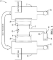
- FIG. 1 Shown in Fig. 1 is flow schematic of a Unitary HPAC System 10 configured to captures waste heat energy from one part of a motor vehicle and puts it to beneficial use within another part of the vehicle.
- the Unitary HPAC System 10 includes a refrigerant loop 12 in thermal communication with a cold coolant loop 14 and a hot coolant loop 16.
- the main components of the refrigerant loop 12 include a condenser 18, a refrigerant expansion device 20, and an evaporator 22 hydraulically connected in series in a closed circuit.
- a refrigerant compressor 24 located downstream of the evaporator 22 and upstream of the condenser 18 with respect to the direction of refrigerant flow.
- the compressor 24 is responsible for compressing and cycling a two-phase refrigerant, such as R-134a or R-1234yf, through the refrigerant loop 12 of the Unitary HPAC System 10.
- the hot coolant loop 16 includes a hot heat exchanger 26 in thermal communication with the condenser 18 and a hot coolant pump 28 that circulates a hot coolant through the hot heat exchanger 26.
- the cold coolant loop 14 includes a cold heat exchanger 30 in thermal communication with the evaporator 22 and a cold coolant pump 32 that circulates a cold coolant through the cold heat exchanger 30.
- the cold coolant loop 14 may scavenge waste heat from various vehicle heat sources, such as the electric drive motor, power electronics, and an internal combustion engine of a hybrid vehicle, thereby cooling the various heat sources.
- the refrigerant loop 12 transfers, or pumps, the heat from the cold coolant loop 14 to the hot coolant loop 16, which in turn transfer the heat to various components throughout the vehicle for beneficial use, such as a comfort heat exchanger 42 to provide supplemental heat to the passenger compartment.
- the flow paths of the cold and hot coolant loops 14, 16 throughout the vehicle may be reconfigured based on the cooling and heating needs of the vehicle.
- the cold and hot coolant loops 14, 16 may include a myriad of interconnecting branches with remotely activated valves 40 at strategic nodes that may be reconfigured to redefine the flow paths of the respective coolant loops 14, 16 to selectively provide cold or hot coolant flow to designated heat exchangers.
- the refrigerant loop 12 transfers the heat energy from the cold coolant loop 14 to the hot coolant loop 16.
- the cold coolant loop 14 shown in single dashed lines, is configured to allow cold coolant flow through a comfort heat exchanger 42 to cool the air to the occupant compartment and, if desired, to a battery heat exchanger 46 to cool the batteries
- the hot coolant loop 16 shown in triple dashed lines, is configured to allow hot coolant flow through an external heat exchanger 44, such as a low temperature radiator 44, to dissipate the heat.
- heat pump mode referring to Fig.
- the cold coolant loop 14, shown in single dashed lines, may be directed to internal ancillary heat exchangers 48 to scavenge vehicle internal heat and the external heat exchanger 44 to scavenge heat from the ambient air.
- the hot coolant loop 16, shown in triple dashed lines, may be redirected through the comfort heat exchanger 42 to heat the air to the occupant compartment and, if desired, to the battery heat exchanger 46 to maintain the batteries at an optimal operating temperature.
- the refrigerant flowing through the refrigerant loop 12 does not need to be reversed; it is the reconfiguring of the cold and hot coolant loops 14, 16 that determines whether the system is working in cooling or heat pump modes.
- the refrigerant loop 12 of the current invention is never reversed. A benefit of this is there is no need to reinforce the refrigerant tubing and fittings throughout the refrigerant loop 12 since the low pressure side of the refrigerant loop 12 is not subject to high pressure refrigerant.
- the defrosting takes about 30 seconds and when the hot coolant is sent to the low temperature heat exchanger 44, which is typically located in the front end of the motor vehicle, the hot coolant cools down rapidly because of the high airflow in the front, resulting in loss of heat supplied to the comfort heat exchanger 42. This decreases the heating capacity of the Unitary HPAC System 10, which will reduce the temperature of the conditioned air provided to the passenger compartment, thereby causing discomfort to the passengers.
- the present invention provides a unique system and method for defrosting the low temperature heat exchanger 44 by providing a compressed vapor diversion loop 49 in the Unitary HPAC System 10, or more specifically, in the Unitary HPAC 100.
- the components of the Unitary HPAC 100 is described in detail below and illustrative examples shown in Figs. 5 and 6 .
- Fig. 4 in heat pump and defrost mode, all of the hot compressed refrigerant exiting the compressor may be diverted to the evaporator 22, which is in thermal contact with the cold heat exchanger 30, to quickly warm the cold coolant loop 14 to defrost the low temperature radiator 44.
- the thermal inertia of the hot coolant flowing in the hot coolant loop 16 continues to provide heat to the comfort heat exchanger 42.
- the heat in the cold coolant loop 14 is pumped back into the hot coolant loop 16 to continue supplying heat to the passenger compartment via the comfort heat exchanger 42; thus there is no waste of energy in this process.
- a portion, as opposed to all, of the hot compressed refrigerant exiting the compressor may be diverted to the evaporator 22, thereby providing only the heat necessary to quickly increase the temperature of the cold coolant flowing in the cold coolant loop 14 for defrosting the external heat exchanger 44 without noticably affecting the heat supplied to the passenger compartment.
- diverting all or only a portion of the hot compressed refrigerant to heat the cold coolant loop 14 and not diverting the hot coolant loop 16 avoids materially affecting passenger comfort, since the compressed vapor diversion loop is independent of the hot coolant flow through the comfort heater exchanger 42.
- a compressed vapor diversion loop 49 is provided between the discharge of the compressor 24 and the inlet of the evaporator 22 downstream of the expansion device 20.
- the evaporator 22 is in thermal communication with the cold heat exchanger 30, through which the cold coolant flows scavenging heat from the external heat exchanger 44.
- a proportioning valve 50 may be provided to selectively divert all or a portion of the hot compressed refrigerant from the compressor 24 directly to the evaporator 22 instead of the condenser 18, which is in thermal contact with the hot heat exchanger 26, through which a hot coolant flows.
- a bypass valve 52 may be provided upstream of the expansion device 20 for by-passing the expansion device 20 when the hot compressed refrigerant is being partially diverted to the evaporator 22.
- the bypass valve 52 will prevent the hot compressed refrigerant from being partially expanded to ensure maximum transfer of heat to the cold coolant loop 14.
- the proportioning valve 50 cooperating with the by-pass valve 52 will enable maximum heat from the hot compressed refrigerant exiting the compressor 24 to be proportioned to both the hot coolant loop 16 to allow for continued heat for the passenber compartment and the cold coolant loop 14 to allow for the defrosting of the external heat exchanger 44.
- the diverted hot compressed refrigerant flowing through the evaporator 22 provides sufficient heat to the cold coolant loop 14 to defrost any ice formed on the external heat exchanger 44. This allows the hot coolant loop 16, to continue to be used for cabin heating. Since the defrost cycle requires approximately less than a minute or two, the thermal inertia of the hot coolant will be able to continue to provide heating to the passenger compartment during the defrost cycle.
- the cold coolant loop 14 is still warm and allows this heat to be pumped back up into the hot coolant loop 16 of the circuit, thereby not losing all the heat that was used for defrosting the exterior heat exchanger 44. This will aid in getting the Coefficient of Performance (COP) as high as possible as well as getting the hot coolant to the desired temperature relatively quickly.
- COP Coefficient of Performance
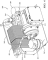
- FIG. 5 Shown in Fig. 5 is an exemplary embodiment of a compact Unitary HPAC 100 having an integral condenser hot heat exchanger assembly 102, a receiver 104, a sub-cooler 106, a thermal expansion valve (TXV) 108, and an integral evaporator/cold heat exchanger assembly 110.
- the Unitary HPAC 100 also includes an electrically driven compressor 112 for the circulation of a typical two-phase refrigerant through a series of refrigerant tubes 113 and electrically driven hot and cold coolant pumps 114, 116 configured to hydraulically connect to the hot coolant loop and cold coolant loop, respectively.
- the compressor may be that of a compact scroll compressor driven by a permanent magnet motor with neodymium or other rare earth magnets.
- the liquid coolant used in the hot and cold coolant loops is generally a mixture of 70% glycol-30% water, which prevents the coolant from freezing or becoming too viscous at the low temperatures needed in integral evaporator/cold heat exchanger
- the integral condenser/hot heat exchanger assembly 102 may be that of a plate-type heat exchanger assembly having a plurality of stamped metal plates 120 stacked and brazed between an upstream end plate 126 and a downstream end plate 128.
- the stamped metal plates include features known to those of ordinary skill in the art, such as openings, bosses about selected openings, and flanges, which when stacked, define a condenser refrigerant passageway for high pressure refrigerant flow and a separate hot coolant passageway for hot coolant flow.
- the plates may include numerous contact points established between adjacent plates to induce turbulence to the fluids flowing through to provide a high heat transfer coefficient.
- the flows of the hot refrigerant and hot coolant through the integral condenser/hot heat exchanger assembly 102 are in non-contact thermal communication; in other words, the two fluids are not intermingle, but are in thermal communication with each other, and may be concurrent or countercurrent flow. Heat energy from the higher temperature refrigerant is transferred to the lower temperature hot coolant; thereby increasing the temperature of the hot coolant as it leaves the integral condenser/hot heat exchanger assembly 102 and returning to the hot coolant loop (not-shown).
- the upstream end plate 126 includes a refrigerant inlet 130 in fluid communication with the discharge side 118 of the electrically driven compressor 112 and a hot coolant inlet 134 in fluid communication with the hot coolant pump 114.
- the downstream end plate 128 includes a refrigerant outlet 132 in fluid communication with the receiver 104 and a hot coolant outlet 136 configured to hydraulically connect to the hot coolant loop.
- the downstream sub-cooler 106 and integral evaporator/cold heat exchanger assembly 110 may also be plate-type heat exchangers.
- the integral evaporator/cold heat exchanger assembly 110 includes a cold coolant inlet 138 and outlet 140, in which the cold coolant outlet 140 is adapted to hydraulically connect to the cold coolant loop (not shown), an evaporator refrigerant passageway for low pressure refrigerant flow, and a separate cold coolant passageway for cold coolant flow.
- the flows of the low pressure refrigerant and cold coolant through the integral evaporator/cold heat exchanger assembly 110 are also in non-contact thermal communication with each other, and may be concurrent or countercurrent flow.
- Heat energy from the higher temperature cold coolant is transferred to the lower temperature evaporating refrigerant, thereby decreasing the temperature of the cold coolant as it leaves the integral evaporator/cold heat exchanger assembly 110 and returning to the cold coolant loop (not-shown).
- FIG. 6 Shown in Figure 6 is an alternative embodiment of the Unitary HPAC 100, in which the integral condenser/hot heat exchanger assembly 102, the receiver 104, the sub-cooler 106, the thermal expansion valve (TXV) 108, and the integral evaporator/cold heat exchanger assembly of the Unitary HPAC 100 shown in Fig. 5 is replaced by a single compact plate-type HPAC heat exchanger 201 assembled from a plurality of stacked and brazed metallic plates.
- An accumulator 294 may be provided downstream, with respect to the flow of refrigerant, of the plate-type HPAC heat exchanger 201 and upstream of the compressor 212.
- the plate-type HPAC heat exchanger 201 includes essentially three joined heat exchanger portions working in conjunction as one integral unit, in which a refrigerant is used to transfer heat energy from a cold coolant loop to a hot coolant loop, thereby cooling the cold coolant loop and heating the hot coolant loop.
- a proportioning diverter valve 150 is added to the compressor 112 discharge line to control the duration of the compressed vapor diversion.
- a refrigerant line 152 is added from the proportion diverter valve 150 to the integral evaporator/cold heat exchanger assembly 110 inlet downstream of the TXV 108.
- a proportioning diverter valve 250 is added in the compressor discharge line downstream of the compressor 212.
- a refrigerant line 252 is then connected to the inlet side of the plate-type HPAC heat exchanger 201. The hot compressed refrigerant is brought into the plate-type HPAC heat exchanger 201.
- Figure 7 shows the refrigeration cycle of the current system on a pressure-enthalpy diagram.
- the work put into the system by the compressor is shown by line 1-2.
- line 2-3 heat from the refrigerant is rejected and transferred to the coolant.
- the refrigerant changes phase from vapor to liquid.
- the refrigerant flows through the expansion device, line 3-4. This process drops the temperature and pressure of the refrigerant and causes some of the liquid to flash back to vapor.
- the liquid-vapor refrigerant mixture flows through the cold heat exchanger, it absorbs heat from the coolant. This heat causes the refrigerant to boil, changing back to vapor before returning to the compressor, point 1.
- the cycle for the compressed vapor diversion is shown in Figure 8 .
- the work put into the system by the compressor is shown by line 1'-2'.
- the hot compressed refrigerant from the compressor is not directed to the condenser. Instead, the diverter valve directs it to the evaporator, line 2'-3'.
- the refrigerant flows through the evaporator , transfers the heat from the compressor to the coolant flowing through the cold heat exchanger , and then returns to the compressor, shown by line 3'- 1'.
- the coolant that was heated by the cold heat exchanger is sent to the low temperature radiator defrosting.
Landscapes
- Engineering & Computer Science (AREA)
- Physics & Mathematics (AREA)
- Thermal Sciences (AREA)
- Mechanical Engineering (AREA)
- General Engineering & Computer Science (AREA)
- Air-Conditioning For Vehicles (AREA)
- Other Air-Conditioning Systems (AREA)
- Compression-Type Refrigeration Machines With Reversible Cycles (AREA)
Claims (5)
- Système de climatiseur à pompe à chaleur unitaire (10), comprenant :une boucle de fluide frigoporteur froid (14),une boucle de fluide frigoporteur chaud (16),une boucle de réfrigérant (12) incluant :un condenseur (18) configuré pour condenser un réfrigérant comprimé chaud en un réfrigérant liquide,un détendeur (20) configuré pour recevoir et partiellement détendre le réfrigérant liquide dudit condenseur (18) en un réfrigérant en phase vapeur-liquide,un évaporateur (22) en aval dudit détendeur (20) configuré pour faire s'évaporer le réfrigérant en phase vapeur-liquide en un réfrigérant vapeur froid et est en communication thermique avec ladite boucle de fluide frigoporteur froid (14) ayant un échangeur thermique externe (44), etun compresseur (24) configuré pour recevoir et comprimer le réfrigérant vapeur froid dudit évaporateur (22) en réfrigérant comprimé chaud audit condenseur (18),dans lequel ladite boucle de réfrigérant (12) inclut des moyens pour rediriger sélectivement au moins une portion dudit réfrigérant comprimé chaud sortant dudit compresseur (24) audit évaporateur (22) ;la boucle de réfrigérant (12) en communication thermique avec ladite boucle de fluide frigoporteur froid (14) et ladite boucle de fluide frigoporteur chaud (16) ;la boucle de fluide frigoporteur froid (14) inclut un échangeur thermique froid (30) en communication thermique avec l'évaporateur (22) ;une boucle de redirection de réfrigérant (49) reliant hydrauliquement le réfrigérant comprimé chaud sortant dudit compresseur (24) à l'entrée de l'évaporateur (22) en aval du détendeur (20), (22),dans lequel lesdits moyens pour rediriger sélectivement au moins une portion dudit réfrigérant comprimé chaud incluent un répartiteur (50) dans ladite boucle de réfrigérant (12) entre ledit compresseur (24) et ledit condenseur (18), dans lequel ledit répartiteur (50) peut fonctionner pour rediriger entre zéro et 100 pourcent dudit réfrigérant comprimé chaud sortant dudit compresseur (24) audit évaporateur (22),dans lequel ladite boucle de redirection de réfrigérant (49) relie hydrauliquement ledit répartiteur (50) à une entrée dudit évaporateur (22),dans lequel ladite boucle de réfrigérant (12) inclut une soupape de dérivation (52) positionnée en aval dudit condenseur (18) et en amont dudit détendeur (20),dans lequel ladite soupape de dérivation (52) peut fonctionner pour dériver le réfrigérant liquide sortant dudit condenseur (18) à ladite boucle de redirection (49) lorsque ledit répartiteur (50) redirige moins de 100 pourcent de réfrigérant comprimé chaud dudit compresseur (24).
- Système de climatiseur à pompe à chaleur unitaire (10) selon la revendication 1, dans lequel :ledit échangeur thermique externe (44) est susceptible de givrer, etledit répartiteur (50) peut fonctionner pour rediriger au moins une portion dudit réfrigérant comprimé chaud audit évaporateur (22) pour fournir suffisamment de chaleur à ladite boucle de fluide frigoporteur froid (14) pour dégivrer ledit échangeur thermique externe (44).
- Système de climatiseur à pompe à chaleur unitaire (10) selon la revendication 1, dans lequel :ledit échangeur thermique externe (44) est susceptible de givrer, etlesdits moyens pour rediriger sélectivement au moins une portion dudit réfrigérant comprimé chaud sortant dudit compresseur (24) directement audit évaporateur (22) peuvent fonctionner pour fournir suffisamment d'énergie thermique à ladite boucle de fluide frigoporteur froid (14) pour dégivrer ledit échangeur thermique externe (44).
- Procédé pour dégivrer un échangeur thermique externe (44) d'un système de climatiseur à pompe à chaleur unitaire (10) selon l'une quelconque des revendications 1 à 3, comprenant une étape de :
redirection d'au moins une portion dudit réfrigérant comprimé chaud sortant dudit compresseur (24) par l'intermédiaire de ladite boucle de redirection de réfrigérant (49) audit évaporateur (22) pour transférer suffisamment de chaleur dudit réfrigérant comprimé chaud à ladite boucle de fluide frigoporteur froid (14) pour dégivrer ledit échangeur thermique externe (44). - Procédé selon la revendication 4, comprenant en outre une étape de :détection du givrage dudit échangeur thermique externe (44) ; etredirection d'une portion suffisante dudit réfrigérant compressé chaud audit évaporateur (22) pour fournir suffisamment de chaleur pour dégivrer ledit échangeur thermique externe (44).
Applications Claiming Priority (3)
| Application Number | Priority Date | Filing Date | Title |
|---|---|---|---|
| US201361777677P | 2013-03-12 | 2013-03-12 | |
| US14/203,903 US9879891B2 (en) | 2011-02-17 | 2014-03-11 | Unitary heat pump air conditioner having a compressed vapor diversion loop |
| PCT/US2014/024043 WO2014143621A1 (fr) | 2013-03-12 | 2014-03-12 | Climatiseur à pompe à chaleur unitaire ayant une boucle de dérivation de vapeur comprimée |
Publications (3)
| Publication Number | Publication Date |
|---|---|
| EP2972019A1 EP2972019A1 (fr) | 2016-01-20 |
| EP2972019A4 EP2972019A4 (fr) | 2017-03-15 |
| EP2972019B1 true EP2972019B1 (fr) | 2018-05-30 |
Family
ID=51537503
Family Applications (1)
| Application Number | Title | Priority Date | Filing Date |
|---|---|---|---|
| EP14764997.4A Not-in-force EP2972019B1 (fr) | 2013-03-12 | 2014-03-12 | Climatiseur à pompe à chaleur unitaire ayant une boucle de dérivation de vapeur comprimée |
Country Status (3)
| Country | Link |
|---|---|
| EP (1) | EP2972019B1 (fr) |
| CN (1) | CN105143795B (fr) |
| WO (1) | WO2014143621A1 (fr) |
Cited By (1)
| Publication number | Priority date | Publication date | Assignee | Title |
|---|---|---|---|---|
| EP3845402A1 (fr) | 2020-01-06 | 2021-07-07 | LG Electronics, Inc. | Dispositif de pompe à chaleur pour véhicule électrique |
Families Citing this family (11)
| Publication number | Priority date | Publication date | Assignee | Title |
|---|---|---|---|---|
| GB2529162B (en) * | 2014-08-11 | 2017-11-08 | Jaguar Land Rover Ltd | A vehicle arrangement |
| US10638648B2 (en) | 2016-04-28 | 2020-04-28 | Ge Energy Power Conversion Technology Ltd. | Cooling system with pressure regulation |
| DE102017100653B4 (de) | 2017-01-13 | 2023-08-24 | Denso Automotive Deutschland Gmbh | Wärmepumpeneinrichtung mit Enteisungsfunktion |
| GB2558914B (en) * | 2017-01-19 | 2021-03-31 | Arrival Ltd | Thermal management unit and system |
| CN108312866A (zh) * | 2018-01-30 | 2018-07-24 | 宁波国创机车装备有限公司 | 一种动力电池冷却加热管理系统及动力电池 |
| CN112406494B (zh) * | 2019-08-23 | 2022-08-09 | 华为技术有限公司 | 用于汽车的热管理系统以及基于该系统的热管理方法 |
| IT201900015376A1 (it) * | 2019-09-02 | 2021-03-02 | Denso Thermal Systems Spa | Sistema per il controllo della temperatura di una batteria in un veicolo e per lo sbrinamento di un radiatore associato a tale sistema. |
| EP3984793B1 (fr) | 2020-10-16 | 2023-11-22 | Volvo Car Corporation | Système de régulation de la température pour véhicules électriques |
| CN113212105B (zh) * | 2021-06-16 | 2022-03-18 | 广州小鹏汽车科技有限公司 | 热管理系统及其控制方法和车辆 |
| CN114523819B (zh) * | 2022-03-30 | 2024-01-19 | 广东美的白色家电技术创新中心有限公司 | 热管理系统、控制方法及装置、计算机程序产品和车辆 |
| DE102022206698B4 (de) * | 2022-06-30 | 2024-02-22 | Zf Friedrichshafen Ag | Wärmeenergiesystem zum Regulieren von Temperaturen eines Fahrzeugs und Fahrzeug mit einem solchen |
Family Cites Families (5)
| Publication number | Priority date | Publication date | Assignee | Title |
|---|---|---|---|---|
| JP3237187B2 (ja) * | 1991-06-24 | 2001-12-10 | 株式会社デンソー | 空調装置 |
| CN2456110Y (zh) * | 2000-12-30 | 2001-10-24 | 广东科龙电器股份有限公司 | 可连续制热的热泵空调器 |
| DK1616610T3 (da) * | 2004-07-13 | 2012-10-22 | Byeong-Seung Lee | Plade-varmeveksler med en adskillelsesfunktion med hensyn til kondenseret fluidum og fremgangsmåde til dens fremstilling |
| ATE552993T1 (de) * | 2008-04-18 | 2012-04-15 | Valeo Systemes Thermiques | Verbesserte heizungs- und luftkühleinheit für ein automobil |
| JP2010260449A (ja) * | 2009-05-07 | 2010-11-18 | Nippon Soken Inc | 車両用空調装置 |
-
2014
- 2014-03-12 WO PCT/US2014/024043 patent/WO2014143621A1/fr active Application Filing
- 2014-03-12 CN CN201480011334.7A patent/CN105143795B/zh not_active Expired - Fee Related
- 2014-03-12 EP EP14764997.4A patent/EP2972019B1/fr not_active Not-in-force
Non-Patent Citations (1)
| Title |
|---|
| None * |
Cited By (1)
| Publication number | Priority date | Publication date | Assignee | Title |
|---|---|---|---|---|
| EP3845402A1 (fr) | 2020-01-06 | 2021-07-07 | LG Electronics, Inc. | Dispositif de pompe à chaleur pour véhicule électrique |
Also Published As
| Publication number | Publication date |
|---|---|
| WO2014143621A1 (fr) | 2014-09-18 |
| EP2972019A1 (fr) | 2016-01-20 |
| EP2972019A4 (fr) | 2017-03-15 |
| CN105143795A (zh) | 2015-12-09 |
| CN105143795B (zh) | 2017-05-24 |
Similar Documents
| Publication | Publication Date | Title |
|---|---|---|
| US9879891B2 (en) | Unitary heat pump air conditioner having a compressed vapor diversion loop | |
| EP2972019B1 (fr) | Climatiseur à pompe à chaleur unitaire ayant une boucle de dérivation de vapeur comprimée | |
| EP2676096B1 (fr) | Échangeur de chaleur de climatiseur à pompe à chaleur du type à plaques pour un climatiseur à thermopompe individuelle | |
| US9239193B2 (en) | Unitary heat pump air conditioner having a heat exchanger with an integral receiver and sub-cooler | |
| US11117444B2 (en) | Heat pump system for vehicle | |
| CN109501552B (zh) | 用于车辆的热泵系统 | |
| CN112092566B (zh) | 一种热管理系统 | |
| US7063137B2 (en) | Heat pump with secondary loop air-conditioning system | |
| EP2629040B1 (fr) | Climatiseur à pompe à chaleur unitaire comportant un échangeur de chaleur avec un récepteur monobloc et refroidisseur secondaire | |
| US20140060102A1 (en) | Mild ambient vehicular heat pump system | |
| CN112428768A (zh) | 热管理系统 | |
| WO2011087001A1 (fr) | Système de climatisation pour véhicule | |
| JP2015101180A (ja) | ヒートポンプシステム | |
| CN110831796B (zh) | 包括具有热交换器的制冷剂回路的用于车辆的制冷设备以及用于这种制冷设备的热交换器 | |
| CN113454407B (zh) | 用于电动或混合动力机动车辆的热管理的装置 | |
| JP6590321B2 (ja) | 車両用空調装置 | |
| CN107074069A (zh) | 热泵式车辆用空调系统 | |
| CN109982877B (zh) | 车辆热泵系统 | |
| CN212950033U (zh) | 热管理系统 | |
| KR102644746B1 (ko) | 차량용 냉난방 시스템 | |
| CN113330259B (zh) | 机动车辆空调回路 | |
| KR102644748B1 (ko) | 차량용 냉난방 시스템 | |
| KR102644744B1 (ko) | 차량용 냉난방 시스템 | |
| CN113263889A (zh) | 热管理系统 | |
| CN112313099A (zh) | 用于车辆的热处理系统 |
Legal Events
| Date | Code | Title | Description |
|---|---|---|---|
| PUAI | Public reference made under article 153(3) epc to a published international application that has entered the european phase |
Free format text: ORIGINAL CODE: 0009012 |
|
| 17P | Request for examination filed |
Effective date: 20150818 |
|
| AK | Designated contracting states |
Kind code of ref document: A1 Designated state(s): AL AT BE BG CH CY CZ DE DK EE ES FI FR GB GR HR HU IE IS IT LI LT LU LV MC MK MT NL NO PL PT RO RS SE SI SK SM TR |
|
| AX | Request for extension of the european patent |
Extension state: BA ME |
|
| DAX | Request for extension of the european patent (deleted) | ||
| A4 | Supplementary search report drawn up and despatched |
Effective date: 20170209 |
|
| RIC1 | Information provided on ipc code assigned before grant |
Ipc: F28F 3/00 20060101ALI20170203BHEP Ipc: F25D 17/00 20060101AFI20170203BHEP Ipc: B60H 1/00 20060101ALI20170203BHEP Ipc: F25B 29/00 20060101ALI20170203BHEP Ipc: F25B 47/02 20060101ALI20170203BHEP |
|
| GRAP | Despatch of communication of intention to grant a patent |
Free format text: ORIGINAL CODE: EPIDOSNIGR1 |
|
| STAA | Information on the status of an ep patent application or granted ep patent |
Free format text: STATUS: GRANT OF PATENT IS INTENDED |
|
| RIC1 | Information provided on ipc code assigned before grant |
Ipc: F28F 3/00 20060101ALI20171127BHEP Ipc: F25B 29/00 20060101ALI20171127BHEP Ipc: F25B 47/02 20060101ALI20171127BHEP Ipc: F25D 17/00 20060101AFI20171127BHEP Ipc: B60H 1/00 20060101ALI20171127BHEP |
|
| INTG | Intention to grant announced |
Effective date: 20171221 |
|
| GRAS | Grant fee paid |
Free format text: ORIGINAL CODE: EPIDOSNIGR3 |
|
| GRAA | (expected) grant |
Free format text: ORIGINAL CODE: 0009210 |
|
| STAA | Information on the status of an ep patent application or granted ep patent |
Free format text: STATUS: THE PATENT HAS BEEN GRANTED |
|
| RAP1 | Party data changed (applicant data changed or rights of an application transferred) |
Owner name: MAHLE INTERNATIONAL GMBH |
|
| AK | Designated contracting states |
Kind code of ref document: B1 Designated state(s): AL AT BE BG CH CY CZ DE DK EE ES FI FR GB GR HR HU IE IS IT LI LT LU LV MC MK MT NL NO PL PT RO RS SE SI SK SM TR |
|
| REG | Reference to a national code |
Ref country code: GB Ref legal event code: FG4D |
|
| REG | Reference to a national code |
Ref country code: CH Ref legal event code: EP |
|
| REG | Reference to a national code |
Ref country code: AT Ref legal event code: REF Ref document number: 1004028 Country of ref document: AT Kind code of ref document: T Effective date: 20180615 |
|
| REG | Reference to a national code |
Ref country code: IE Ref legal event code: FG4D |
|
| REG | Reference to a national code |
Ref country code: DE Ref legal event code: R096 Ref document number: 602014026289 Country of ref document: DE |
|
| REG | Reference to a national code |
Ref country code: NL Ref legal event code: MP Effective date: 20180530 |
|
| REG | Reference to a national code |
Ref country code: LT Ref legal event code: MG4D |
|
| PG25 | Lapsed in a contracting state [announced via postgrant information from national office to epo] |
Ref country code: BG Free format text: LAPSE BECAUSE OF FAILURE TO SUBMIT A TRANSLATION OF THE DESCRIPTION OR TO PAY THE FEE WITHIN THE PRESCRIBED TIME-LIMIT Effective date: 20180830 Ref country code: FI Free format text: LAPSE BECAUSE OF FAILURE TO SUBMIT A TRANSLATION OF THE DESCRIPTION OR TO PAY THE FEE WITHIN THE PRESCRIBED TIME-LIMIT Effective date: 20180530 Ref country code: LT Free format text: LAPSE BECAUSE OF FAILURE TO SUBMIT A TRANSLATION OF THE DESCRIPTION OR TO PAY THE FEE WITHIN THE PRESCRIBED TIME-LIMIT Effective date: 20180530 Ref country code: NO Free format text: LAPSE BECAUSE OF FAILURE TO SUBMIT A TRANSLATION OF THE DESCRIPTION OR TO PAY THE FEE WITHIN THE PRESCRIBED TIME-LIMIT Effective date: 20180830 Ref country code: SE Free format text: LAPSE BECAUSE OF FAILURE TO SUBMIT A TRANSLATION OF THE DESCRIPTION OR TO PAY THE FEE WITHIN THE PRESCRIBED TIME-LIMIT Effective date: 20180530 Ref country code: ES Free format text: LAPSE BECAUSE OF FAILURE TO SUBMIT A TRANSLATION OF THE DESCRIPTION OR TO PAY THE FEE WITHIN THE PRESCRIBED TIME-LIMIT Effective date: 20180530 Ref country code: CY Free format text: LAPSE BECAUSE OF FAILURE TO SUBMIT A TRANSLATION OF THE DESCRIPTION OR TO PAY THE FEE WITHIN THE PRESCRIBED TIME-LIMIT Effective date: 20180530 |
|
| PG25 | Lapsed in a contracting state [announced via postgrant information from national office to epo] |
Ref country code: LV Free format text: LAPSE BECAUSE OF FAILURE TO SUBMIT A TRANSLATION OF THE DESCRIPTION OR TO PAY THE FEE WITHIN THE PRESCRIBED TIME-LIMIT Effective date: 20180530 Ref country code: RS Free format text: LAPSE BECAUSE OF FAILURE TO SUBMIT A TRANSLATION OF THE DESCRIPTION OR TO PAY THE FEE WITHIN THE PRESCRIBED TIME-LIMIT Effective date: 20180530 Ref country code: HR Free format text: LAPSE BECAUSE OF FAILURE TO SUBMIT A TRANSLATION OF THE DESCRIPTION OR TO PAY THE FEE WITHIN THE PRESCRIBED TIME-LIMIT Effective date: 20180530 Ref country code: GR Free format text: LAPSE BECAUSE OF FAILURE TO SUBMIT A TRANSLATION OF THE DESCRIPTION OR TO PAY THE FEE WITHIN THE PRESCRIBED TIME-LIMIT Effective date: 20180831 |
|
| REG | Reference to a national code |
Ref country code: AT Ref legal event code: MK05 Ref document number: 1004028 Country of ref document: AT Kind code of ref document: T Effective date: 20180530 |
|
| PG25 | Lapsed in a contracting state [announced via postgrant information from national office to epo] |
Ref country code: NL Free format text: LAPSE BECAUSE OF FAILURE TO SUBMIT A TRANSLATION OF THE DESCRIPTION OR TO PAY THE FEE WITHIN THE PRESCRIBED TIME-LIMIT Effective date: 20180530 |
|
| PG25 | Lapsed in a contracting state [announced via postgrant information from national office to epo] |
Ref country code: PL Free format text: LAPSE BECAUSE OF FAILURE TO SUBMIT A TRANSLATION OF THE DESCRIPTION OR TO PAY THE FEE WITHIN THE PRESCRIBED TIME-LIMIT Effective date: 20180530 Ref country code: EE Free format text: LAPSE BECAUSE OF FAILURE TO SUBMIT A TRANSLATION OF THE DESCRIPTION OR TO PAY THE FEE WITHIN THE PRESCRIBED TIME-LIMIT Effective date: 20180530 Ref country code: SK Free format text: LAPSE BECAUSE OF FAILURE TO SUBMIT A TRANSLATION OF THE DESCRIPTION OR TO PAY THE FEE WITHIN THE PRESCRIBED TIME-LIMIT Effective date: 20180530 Ref country code: AT Free format text: LAPSE BECAUSE OF FAILURE TO SUBMIT A TRANSLATION OF THE DESCRIPTION OR TO PAY THE FEE WITHIN THE PRESCRIBED TIME-LIMIT Effective date: 20180530 Ref country code: DK Free format text: LAPSE BECAUSE OF FAILURE TO SUBMIT A TRANSLATION OF THE DESCRIPTION OR TO PAY THE FEE WITHIN THE PRESCRIBED TIME-LIMIT Effective date: 20180530 Ref country code: RO Free format text: LAPSE BECAUSE OF FAILURE TO SUBMIT A TRANSLATION OF THE DESCRIPTION OR TO PAY THE FEE WITHIN THE PRESCRIBED TIME-LIMIT Effective date: 20180530 Ref country code: CZ Free format text: LAPSE BECAUSE OF FAILURE TO SUBMIT A TRANSLATION OF THE DESCRIPTION OR TO PAY THE FEE WITHIN THE PRESCRIBED TIME-LIMIT Effective date: 20180530 |
|
| PG25 | Lapsed in a contracting state [announced via postgrant information from national office to epo] |
Ref country code: SM Free format text: LAPSE BECAUSE OF FAILURE TO SUBMIT A TRANSLATION OF THE DESCRIPTION OR TO PAY THE FEE WITHIN THE PRESCRIBED TIME-LIMIT Effective date: 20180530 Ref country code: IT Free format text: LAPSE BECAUSE OF FAILURE TO SUBMIT A TRANSLATION OF THE DESCRIPTION OR TO PAY THE FEE WITHIN THE PRESCRIBED TIME-LIMIT Effective date: 20180530 |
|
| REG | Reference to a national code |
Ref country code: DE Ref legal event code: R097 Ref document number: 602014026289 Country of ref document: DE |
|
| PLBE | No opposition filed within time limit |
Free format text: ORIGINAL CODE: 0009261 |
|
| STAA | Information on the status of an ep patent application or granted ep patent |
Free format text: STATUS: NO OPPOSITION FILED WITHIN TIME LIMIT |
|
| 26N | No opposition filed |
Effective date: 20190301 |
|
| PG25 | Lapsed in a contracting state [announced via postgrant information from national office to epo] |
Ref country code: SI Free format text: LAPSE BECAUSE OF FAILURE TO SUBMIT A TRANSLATION OF THE DESCRIPTION OR TO PAY THE FEE WITHIN THE PRESCRIBED TIME-LIMIT Effective date: 20180530 |
|
| PG25 | Lapsed in a contracting state [announced via postgrant information from national office to epo] |
Ref country code: MC Free format text: LAPSE BECAUSE OF FAILURE TO SUBMIT A TRANSLATION OF THE DESCRIPTION OR TO PAY THE FEE WITHIN THE PRESCRIBED TIME-LIMIT Effective date: 20180530 |
|
| PGFP | Annual fee paid to national office [announced via postgrant information from national office to epo] |
Ref country code: FR Payment date: 20190903 Year of fee payment: 6 |
|
| REG | Reference to a national code |
Ref country code: CH Ref legal event code: PL |
|
| GBPC | Gb: european patent ceased through non-payment of renewal fee |
Effective date: 20190312 |
|
| PG25 | Lapsed in a contracting state [announced via postgrant information from national office to epo] |
Ref country code: AL Free format text: LAPSE BECAUSE OF FAILURE TO SUBMIT A TRANSLATION OF THE DESCRIPTION OR TO PAY THE FEE WITHIN THE PRESCRIBED TIME-LIMIT Effective date: 20180530 Ref country code: LU Free format text: LAPSE BECAUSE OF NON-PAYMENT OF DUE FEES Effective date: 20190312 |
|
| REG | Reference to a national code |
Ref country code: BE Ref legal event code: MM Effective date: 20190331 |
|
| PG25 | Lapsed in a contracting state [announced via postgrant information from national office to epo] |
Ref country code: IE Free format text: LAPSE BECAUSE OF NON-PAYMENT OF DUE FEES Effective date: 20190312 Ref country code: GB Free format text: LAPSE BECAUSE OF NON-PAYMENT OF DUE FEES Effective date: 20190312 Ref country code: CH Free format text: LAPSE BECAUSE OF NON-PAYMENT OF DUE FEES Effective date: 20190331 Ref country code: LI Free format text: LAPSE BECAUSE OF NON-PAYMENT OF DUE FEES Effective date: 20190331 |
|
| PG25 | Lapsed in a contracting state [announced via postgrant information from national office to epo] |
Ref country code: BE Free format text: LAPSE BECAUSE OF NON-PAYMENT OF DUE FEES Effective date: 20190331 |
|
| PG25 | Lapsed in a contracting state [announced via postgrant information from national office to epo] |
Ref country code: TR Free format text: LAPSE BECAUSE OF FAILURE TO SUBMIT A TRANSLATION OF THE DESCRIPTION OR TO PAY THE FEE WITHIN THE PRESCRIBED TIME-LIMIT Effective date: 20180530 |
|
| PG25 | Lapsed in a contracting state [announced via postgrant information from national office to epo] |
Ref country code: PT Free format text: LAPSE BECAUSE OF FAILURE TO SUBMIT A TRANSLATION OF THE DESCRIPTION OR TO PAY THE FEE WITHIN THE PRESCRIBED TIME-LIMIT Effective date: 20181001 Ref country code: MT Free format text: LAPSE BECAUSE OF NON-PAYMENT OF DUE FEES Effective date: 20190312 |
|
| PG25 | Lapsed in a contracting state [announced via postgrant information from national office to epo] |
Ref country code: FR Free format text: LAPSE BECAUSE OF NON-PAYMENT OF DUE FEES Effective date: 20200331 |
|
| PG25 | Lapsed in a contracting state [announced via postgrant information from national office to epo] |
Ref country code: IS Free format text: LAPSE BECAUSE OF FAILURE TO SUBMIT A TRANSLATION OF THE DESCRIPTION OR TO PAY THE FEE WITHIN THE PRESCRIBED TIME-LIMIT Effective date: 20180930 |
|
| PG25 | Lapsed in a contracting state [announced via postgrant information from national office to epo] |
Ref country code: HU Free format text: LAPSE BECAUSE OF FAILURE TO SUBMIT A TRANSLATION OF THE DESCRIPTION OR TO PAY THE FEE WITHIN THE PRESCRIBED TIME-LIMIT; INVALID AB INITIO Effective date: 20140312 |
|
| PGFP | Annual fee paid to national office [announced via postgrant information from national office to epo] |
Ref country code: DE Payment date: 20210427 Year of fee payment: 8 |
|
| PG25 | Lapsed in a contracting state [announced via postgrant information from national office to epo] |
Ref country code: MK Free format text: LAPSE BECAUSE OF FAILURE TO SUBMIT A TRANSLATION OF THE DESCRIPTION OR TO PAY THE FEE WITHIN THE PRESCRIBED TIME-LIMIT Effective date: 20180530 |
|
| REG | Reference to a national code |
Ref country code: DE Ref legal event code: R119 Ref document number: 602014026289 Country of ref document: DE |
|
| PG25 | Lapsed in a contracting state [announced via postgrant information from national office to epo] |
Ref country code: DE Free format text: LAPSE BECAUSE OF NON-PAYMENT OF DUE FEES Effective date: 20221001 |