EP2972018B1 - Nucleator for generating ice crystals for seeding water droplets in snow-making systems - Google Patents
Nucleator for generating ice crystals for seeding water droplets in snow-making systems Download PDFInfo
- Publication number
- EP2972018B1 EP2972018B1 EP14763210.3A EP14763210A EP2972018B1 EP 2972018 B1 EP2972018 B1 EP 2972018B1 EP 14763210 A EP14763210 A EP 14763210A EP 2972018 B1 EP2972018 B1 EP 2972018B1
- Authority
- EP
- European Patent Office
- Prior art keywords
- nucleator
- water
- nozzle
- snow
- nozzles
- Prior art date
- Legal status (The legal status is an assumption and is not a legal conclusion. Google has not performed a legal analysis and makes no representation as to the accuracy of the status listed.)
- Active
Links
Images


Classifications
-
- F—MECHANICAL ENGINEERING; LIGHTING; HEATING; WEAPONS; BLASTING
- F25—REFRIGERATION OR COOLING; COMBINED HEATING AND REFRIGERATION SYSTEMS; HEAT PUMP SYSTEMS; MANUFACTURE OR STORAGE OF ICE; LIQUEFACTION SOLIDIFICATION OF GASES
- F25C—PRODUCING, WORKING OR HANDLING ICE
- F25C3/00—Processes or apparatus specially adapted for producing ice or snow for winter sports or similar recreational purposes, e.g. for sporting installations; Producing artificial snow
- F25C3/04—Processes or apparatus specially adapted for producing ice or snow for winter sports or similar recreational purposes, e.g. for sporting installations; Producing artificial snow for sledging or ski trails; Producing artificial snow
-
- F—MECHANICAL ENGINEERING; LIGHTING; HEATING; WEAPONS; BLASTING
- F25—REFRIGERATION OR COOLING; COMBINED HEATING AND REFRIGERATION SYSTEMS; HEAT PUMP SYSTEMS; MANUFACTURE OR STORAGE OF ICE; LIQUEFACTION SOLIDIFICATION OF GASES
- F25C—PRODUCING, WORKING OR HANDLING ICE
- F25C2303/00—Special arrangements or features for producing ice or snow for winter sports or similar recreational purposes, e.g. for sporting installations; Special arrangements or features for producing artificial snow
- F25C2303/048—Snow making by using means for spraying water
- F25C2303/0481—Snow making by using means for spraying water with the use of compressed air
Definitions
- the present invention relates generally to snow-making equipment. More particularly, this invention relates to a nucleator for generating ice crystals for seeding water droplets in snow-making systems.
- Fan guns consist of a large barrel with an enclosed electric fan that forces large volumes of ambient air through the barrel.
- Each bank can consist of up to 90 small capacity hollow cone nozzles which produce very fine particles. The water particles are projected into the ambient air by the large volume of air that the fan produces.
- Fan guns may include an outer ring that is called the nucleating ring. This ring has a small number of miniature air/water nozzles that operate in the same way as an internal mix air/water gun. An onboard compressor is used to operate this ring.
- the nucleating ring's primary role is to produce ice crystals.
- the ice crystals are carried along the outside of the bulk water plume for a distance before becoming ingested into the plume thus nucleating the bulk water plume.
- Operation of the fan gun is achieved by opening one bank of nozzles at a time and altering the water pressure to the nozzles. Once full pressure is achieved on a bank another bank is opened and the water pressure is adjusted.
- Internal mix air and water guns consist of a compressed air line and a water line converging into a common chamber with an exit orifice. Compressed air enters the common chamber and expands breaking up the water stream into smaller particles and projecting them into the ambient air. Operation of the gun is achieved by regulating the water pressure entering the common chamber.
- a common feature of the internal mix gun is that when water flow is increased air flow is decreased and vice versa. Water pressure cannot usually exceed the air pressure which is usually 80-125 psi.
- External mix air and water guns usually consist of a configuration of fixed orifice flat jet nozzles arranged on a head that spray water into the ambient air.
- the head is usually put on a mast in order to give the water droplets more hang time due to the fact there is no compressed air to break the water droplets into smaller particles or to propel them.
- the external mix guns may include nucleating nozzles that use small internal mix nozzles to produce ice crystals which are directed into the bulk water plume. Control of the gun may be achieved by changing the fixed orifice flat jet nozzles for a different size or opening banks of nozzles as with the fan gun.
- the snow making machine disclosed in U.S. Patent No. 5 400 966 A comprises a housing having a frusto-conical section that provides for maintaining the generated velocity of a high-volume air flow out through a discharge outlet and with a nucleator disposed inside the housing to generate a wide angle round spray pattern of ice crystal nuclei that diverge towards the discharge outlet without impinging on the inside of the housing.
- a spray nozzle manifold is mounted annularly around the discharge outlet and supports a plurality of water nozzles comprising primary water nozzles that are automatically actuated when the machine is turned on to inject a primary water shower into the air flow, which water shower commingles with the ice crystal nuclei to thereby form ice granules as the two travel through the cold ambient air, and secondary water nozzles that are selectively actuatable to augment the primary water shower.
- Water only snow guns have no compressed air or nucleating nozzles.
- the head of a water only snow gun comprises a number of flat jet nozzles assembled on a high mast, usually a minimum of 6 m in height.
- Snow guns of this type can only be used at temperatures starting at -6° C and work better with a high temperature nucleation additive.
- U.S. Patent No. 6 793 148 B2 A method and apparatus for producing man-made snow without using either compressed air or high-speed fans is disclosed in U.S. Patent No. 6 793 148 B2 .
- the method makes use of a special water nozzle that is designed to provide a high volume spray of water particles that, owing to their size distribution in the spray, are readily susceptible to conversion to ice crystals as they settle to earth under favorable ambient conditions.
- water applied to the nozzle is seeded with artificial nucleation sites so that water particles in a spray containing such sites are more susceptible to conversion to ice crystals as the particles settle to earth.
- snow guns or snow lances are employed with particular application in winter sports recreation areas.
- the most effective way to generate artificial snow is to nucleate water droplets projected into cold air.
- the stream of tiny water droplets is thus mixed in the atmosphere with a stream of nucleating agents, typically tiny ice crystals.
- the two different streams of water particles are configured to intersect in a region referred to as a germination region where snow may be formed by the combination of the two different streams of water particles.
- the ice-seeded water droplets form snowflakes as they continue to freeze along their gravity dependent trajectories in the air and eventually fall to the ground to form snow. This artificial snow is particularly useful for supplementing natural snowfall at ski and snowboard resorts.
- nucleating agents may consist of tiny ice particles or nuclei which may be formed using a "nucleator".
- a nucleator generally forms the stream of tiny ice particles using compressed air and cold water in a mixing chamber before expelling the tiny ice particles out of an exit orifice or nozzle.
- U.S. Patent Application Publication No. 2011/0049258 A1 to Lehner et al. discloses a conventional nucleator nozzle having an axial compressed air inlet opening at one end that directs compressed air into an axial nozzle channel.
- This conventional nucleator nozzle also includes a lateral water inlet opening which feeds water into the nozzle channel at an angle perpendicular to the nozzle channel axis.
- the compressed air and water combine in a mixing chamber portion of the axial nozzle channel.
- the combined water and air mixture is then directed toward an exit orifice or nozzle.
- the exit orifice or nozzle of Lehner et al. is a conventional convergent-divergent nozzle configuration. That is to say that the nozzle channel tapers in diameter in a first section down to a core, or narrowest, diameter. In a second expanding region, the nozzle channel expands from the core diameter to an outlet opening with greater diameter than the core diameter.
- the expanding region of a convergent-divergent nozzle typically generates a negative pressure which, when combined with the compressed air and water mixture, generates tiny ice particles when ejected into cold air.
- nucleators While conventional nucleators, including those disclosed in Lehner et al. generate nucleating particles useful for snow-making, improvements to nucleators are needed to increase the efficiency and reduce the cost of operation while offering a more robust snow-making gun that operates in a wide range of ambient conditions.
- the present invention defined by claim 1 is an improved nucleator for generating ice crystals for seeding water droplets in snow-making systems. Atomized water droplets can more easily be converted to snow by using a nucleator. Embodiments of a snow-making gun including the novel nucleator are also described.
- the embodiment of a nucleator includes a mixing chamber including a compressed air inlet for receiving compressed air directed along a mixing chamber axis.
- the embodiment of a mixing chamber further includes a water inlet for receiving water toward the mixing chamber axis and an exit orifice for delivering a mixture of compressed air and water.
- the mixing chamber includes a water filter for filtering water prior to passing through the water inlet, the water filter comprising a cylindrical mesh particle filter inside a cylindrical wire filter.
- the embodiment of a nucleator further includes a nucleator block for receiving the mixture and configured for dividing and directing the mixture into a plurality of nozzle channels.
- each nozzle channel lies in a plane perpendicular to, and separated from, one another by a select number of degrees.
- the embodiment of a nucleator further includes a plurality of nucleator nozzles, each of the plurality of nucleator nozzles configured with a nozzle inlet and a nozzle outlet, each of the plurality of nucleator nozzles further configured for receiving one of the plurality of nozzle channels at the nozzle inlet and continuously pressurizing the mixture along a convergent portion of the nozzle, thereby creating a pressurized mixture until the pressurized mixture reaches a core diameter of the nozzle, the pressurized mixture passing through the core diameter and directed through a divergent portion of the nozzle channel where the pressurized mixture depressurizes until exiting the nozzle outlet as tiny ice crystals.
- the present invention is an improved nucleator for generating ice crystals for seeding water droplets in snow-making systems. Atomized water droplets can more easily be converted to snow by using a nucleator. Embodiments of a snow-making gun including the novel nucleator are also described.
- the snowmaking process involves spraying water droplets into cold ambient air. Heat from the water droplets is transferred into the ambient air and the water droplets begin to freeze. If there is a sufficient temperature differential between the water droplets along with sufficient hang time in the air, the water droplet will freeze before hitting the ground.
- the volume of water that can be converted into snow depends on many factors. In order to explain the operation of the snowmaking equipment described herein and, in particular, the complexities and important characteristics that result in an improved snow-making technique, it is first necessary to consider, in general terms, the science of snowmaking.
- Snow-making is a heat exchange process. Heat is removed from snowmaking water by evaporative and convective cooling and then released into the surrounding environment. This heat creates a micro-climate inside the snowmaking plume that is distinct relative to ambient conditions.
- Wet bulb temperature the temperature of a water droplet exiting a snow gun is typically between +1° C and +6.5° C. Once a water droplet exits a nozzle aid is released into the air, its temperature falls rapidly due to expansive and convective cooling and evaporative effects. The droplet's temperature will continue to fall until equilibrium is reached. This equilibrium temperature is the wet bulb temperature.
- the wet bulb temperature is as important as dry bulb (ambient) temperature in predicting snow-making success. For example, snow-making temperatures at -2° C and 10% humidity are equivalent to those at -7° C and 90% humidity.
- homogeneous nucleation occurs in pure water in which there is no contact with any other foreign substance or surface.
- the conversion of the liquid state to solid state is done by either lowering temperatures or by changes in pressure.
- temperature is the primary influence on the conversion of water to ice or ice to water.
- the nucleation begins when a very small volume of water molecules reaches the solid state. This small volume of molecules is called the embryo and becomes the basis for further growth until all of the water is converted. The growth process is controlled by the rate of removal of the latent heat being released. Molecules are attaching and detaching from the embryo at roughly equal and very rapid rates.
- Heterogeneous nucleation occurs when ice forms at temperatures above minus 40° C or minus 40° F due to the presence of aforeign material in the water. This foreign material acts as the embryo and grows more rapidly than embryos of pure water. The location at which an ice embryo is formed is called the ice-nucleating site.
- heterogeneous nucleation is governed by two major factors: the free energy change involved in forming the embryo and the dynamics of fluctuating embryo growth.
- the configuration of molecules and energy of interaction at the nucleating site become the dominating influence in the conversion of water to ice.
- Snowmaking involves the process of heterogeneous nucleation. There are many materials and substances which act as nucleators.
- Each one of these materials and substances promotes freezing at a specific temperature or nucleation temperature.
- These nucleators are generally categorized as a high-temperature (i.e. , silver iodide, dry ice, ice and nucleating proteins) or low-temperature (i.e. , calcium, magnesium, dust and silt) nucleators. It is low-temperature nucleators that are found in large numbers in untreated snowmaking water.
- the nucleation temperature of snowmaking water is between -10° C aid -7° C.
- the size of the water droplet or the number of high-temperature nucleators has a significant effect on the temperature at which freezing occurs (nucleation temperature).
- the temperature at which freezing occurs the temperature at which freezing occurs.
- the size of the water droplet decreases, the likelihood that the droplet will contain a high-temperature nucleator also decreases.
- larger water droplets stand a better chance of containing high-temperature nucleators.
- the optimum situation for snowmakers is one in which every droplet of water passing through the snow gun nozzle contains at least one high-temperature nucleator and freezes in the plume.
- the size of the water droplet determines its ability to convert to snow.
- Use of water nozzles and compressed air are two of the predominant methods.
- Small water droplets offer more surface area per water molecule to the ambient air but are prone to evaporation in low humidity and are less likely to have high temperature nucleators present. Being smaller they have less mass and are vulnerable to high winds which can carry them away. Smaller particles also have a lower velocity and a greater hang time.
- Small water droplets are desirable at marginal snowmaking temperatures due to the larger surface area and a greater hang time which aids when there is a low temperature differential with the ambient air. The larger surface area also assists the evaporative cooling effect.
- Another factor to consider in the snow-making process is hang time.
- a snow-making gun has greater production when it is higher in the air. Droplets projected at a higher velocity will also achieve a greater hang time.
- water volume Yet another factor to consider in the snow-making process is water volume. Given the above factors, there is only a certain volume of water that can be converted into snow depending on the efficiencies of the above factors. Control of the water volume should be incorporated into any snow-making gun design to compensate for the change in ambient temperatures.
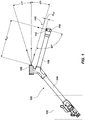
- FIG. 1 is a side view of an embodiment of a snow-making gun 100 incorporating an embodiment of a nucleator 150 according to the present invention.
- the gun 100 may include valving, connectors and controls, shown in dashed box 102, for receiving sources of pressurized water and compressed air (not shown).
- the pressurized water and compressed air may be delivered to a water nozzle head 106 through a snow gun barrel or mast 104.
- the pressurized water and compressed air may further be delivered to a nucleator, shown generally at arrow 150, through a nucleator barrel 108.
- the nucleator 150 may include a nucleator head 110 with one or more nucleator nozzles 112 that eject nucleating particles, generally tiny ice crystals vertically upward, shown schematically at upward arrow above nucleating head 110
- the pressurized water delivered to water nozzle head 106 may be atomized and ejected at high velocity in any assortment of pressurized stream configurations, for example a dual-vectored stream that has high concentrations of atomized water droplets grouped both horizontally and vertically. Conical and flat jet stream configurations are also consistent with the teachings of the present invention.
- This dual-vectored stream of atomized water droplets is shown schematically in FIG. 1 as three arrows exiting the water nozzle head 106 in a plume that has a vertically-oriented disbursement angle of about 34°. There is also a strong horizontal component that is difficult to visualize as it would pass into and out of the surface of the drawing, in this side view.
- This atomized water plume has a trajectory that travels over the top of the nucleator head 110 and intersects its largely vertically-oriented stream of nucleation particles, i.e. , tiny ice crystals in what is referred to as a germination zone.
- the water droplets from the water nozzle head 106 are seeded with the tiny ice crystals from the nucleator 150 and begin to freeze the water droplets as they continue their gravitational and wind-driven trajectories to fall to the ground as snow.
- the optimal insertion point was located to deliver ice crystals from the nucleator where the temperature of dual-vector water plume is close to 32° F (0° C).
- the length of the nucleator barrel 108 was optimized.
- the linear distance, d wn from the water nozzle head to the plane intersecting the axes of nucleator nozzles 112 in the nucleator head 110 is about 660 mm.
- the lower end of a dual-vectored water plume will pass a distance, d nw , of approximately 55 mm away from the nucleator head 110.
- FIG. 2 is a front view of the embodiment of the snow-making gun 100 shown in FIG. 1 .
- FIG. 2 indicates the location of the cross-sectional view of FIG. 3 , according to the present invention.
- FIG. 2 further illustrates the water nozzle head 106, nucleator barrel 108, nucleator head 110, and water and air input and control 102.
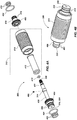
- FIG. 3 is a partial cross-section view of the embodiment of a nucleator 150 shown in FIGS. 1-2 , according to the present invention.
- the nucleator barrel 108 delivers pressurized water 302 and compressed air 304 to nucleator 150.
- the nucleator 150 may include a nucleator barrel cap 306 configured for a threaded engagement with nucleator head 110.
- a nucleator assembly 308 housing a mixing chamber 310, water filter 312, water inlet 314, water chamber 316, nucleator block 320, at least one nucleator nozzle 112 and an a flat jet nozzle 322 used to drain the nucleator head 110.
- compressed air 304 enters the mixing chamber 310 at a proximate end 324 of the mixing chamber assembly 308.
- Pressurized water 302 is filtered at water filter 312 before entering the mixing chamber 310 through water inlet 314.
- the pressurized water 3024 and compressed air 304 generate a mixture of water and air that is directed at a distal end 326 to the nucleator block 320.
- the nucleator block 320 redirects the mixture of water and air into nozzle channels 328, which in turn, feed into the nucleator nozzles 112.
- Another feature of the nucleator assembly described herein is the ease of access to all parts in order to facilitate changing filters 312 and cleaning blockages, and any other servicing or adjustment that may be required.
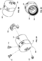
- FIGS. 4A and 4B are an exploded view and an assembled view, respectively, of an embodiment of a mixing chamber assembly 308 according to the present invention.
- the mixing chamber assembly 308 may include two O-rings 402 of suitable dimensions, e.g. , 15 mm inside diameter (ID) and 1.5 mm wide, for mating with corresponding seats 403 on the mixing chamber housing 406.
- the mixing chamber assembly 308 may further include, and one O-ring 404 of suitable dimensions, e.g. , 22 mm ID and 2 mm wide, for mating with seat 405 on the mixing chamber housing 406.
- the mixing chamber 406 may include water inlet 314 with an orifice lining 408.
- the mixing chamber 406 may further include seat 411 for receiving O-ring 410 with suitable dimensions, e.g. , 6 mm ID, 1.5 mm wide, as shown in FIG. 4A .
- Water inlet 314 is covered by water filter 312, which in turn comprises mesh particle filter 412 surrounded in turn by wedge wire filter assembly 414.
- the mixing chamber assembly 308 may further include mixing chamber end cap 416 which is configured for threaded engagement with one end of the mixing chamber housing 406.
- another O-ring 404 and two additional O-rings 418 with suitable dimensions, e.g. , 11.5 mm ID, 1.5 mm wide, are configured to mate with seats 405 and 419, respectively, formed in the mixing chamber end cap 416.
- compressed air enters the mixing chamber 310 at proximate end 324 of mixing chamber housing 406 and pressurized water enters the water inlet 314 and mixes within the mixing chamber.
- the mixture of pressurized water and compressed air exits out of the distal end 326 of the mixing chamber, see, e.g., FIG. 4B .
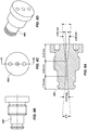
- FIGS. 5A-5C are exploded, right front perspective and right rear perspective views, respectively of the nucleator head assembly 500, according to the present invention. More particularly, FIG. 5A illustrates nucleator head 110 which has fittings for receiving three nucleator nozzles 112, a flat jet nozzle 322 used as a drain and a nucleator block 320.
- FIGS. 6A-6F are various views and section and section views of a particular embodiment of a nucleator block 320, according to the present invention. More particularly, FIG. 6A is a bottom view of the embodiment of a nucleator block 320. FIG. 6B is a right side view of the embodiment of a nucleator block 320. FIG. 6C is front view of the embodiment of a nucleator block 320, showing the section line taken in FIG. 6D. FIG.
- FIG. 6D is a cross-section view of the embodiment of a nucleator block 320 illustrating the nozzle channels 328 and The nucleator block 320 includes a circular mixing chamber receptacle 600, which feeds three nozzle channels 328, one each blocks 602, which in turn house nucleator nozzle receptacles 604.
- FIG. 6E is a section view of the embodiment of a nucleator block 320 as indicated in FIG. 6A.
- FIG. 6F is a perspective view of the embodiment of a nucleator block 320.
- a balancing block 606 is used to offset the three blocks within the circular nucleator head 110.
- One novel feature of the embodiment of a nucleator block 320 shown in FIGS. 6A-6F is that the spaces in between the three blocks 602 housing the nucleator nozzle receptacles 604 in fluid communication with the nucleator nozzle channels 328 allows pressurized water to flow around the blocks 602 and nucleator nozzle receptacles 604, thereby eliminating freezing of the nucleator nozzles 112 (not shown).
- the nucleator block 320 is designed to have positive water circulation around nucleator nozzles 112 (not shown) to prevent the nozzles 112 (not shown) from freezing. Additionally, this design feature provides the capability to thaw frozen nucleator nozzles 112 (not shown) on start-up, through the positive water circulation.
- FIGS. 7A-7D are section, side, front and perspective views, respectively of an embodiment of a nucleator nozzle 700, according to the present invention.
- Nozzle 700 is a convergent-divergent nozzle.
- FIGS. 8A-8D are section, side, front and perspective views, respectively of another embodiment of a nucleator nozzle 800, according to the present invention.
- a nucleator nozzle 800 having a converging conical inlet having a cone angle of about 9.2°, a core diameterof 0.95 mm, and a diverging conical exit orifice having a cone angle of about 11.2° is illustrated.
- nucleator nozzles 700 and 800 are not random and would not be obvious to one of skill in the art because of the number of factors and variable that can be manipulated to affect the quality of nucleation particles generated.
- the particular dimensions for nucleator nozzles 700 and 800 were optimized using a very specific methodology including a number of objectives as described below.
- the overall objective in optimizing the nucleator nozzle dimensions was to create a sufficient number of well-developed ice crystals to seed the water droplet plume of a dual-vector water nozzle producing up to 140 gpm (gallons per minute), while, maintaining good consistent snow quality.
- Another objective was the ability to operate in a wide operational range for the available compressed air, e.g ., 70 to 125 psi (pounds per square inch). To minimize operating costs, another objective was to use as little compressed air as possible, e.g ., about 5 cfm (cubic feet per minute).
- the dimensions relating to the ratio of throat (core diameter) to exit orifice were varied and simulated to determine the highest velocity through the throat section (core diameter), simultaneously with the greatest fluid temperature drop at the exit orifice.
- nucleator nozzles 700 and 800 are removable for cleaning in the unlikely event of blockage, for servicing and for allowing for different sizes of nucleator nozzles for any given application.
- Yet another design feature of the nucleator nozzles 700 and 800 is that they may be constructed from a material having high thermal conductivity (metal, e.g ., aluminum, titanium, stainless steel, etc.) to ensure heat is transferred from surrounding water to prevent freezing and clogging of the nozzle channel.
- metal e.g ., aluminum, titanium, stainless steel, etc.
- the embodiment of a nucleator for generating ice crystals for seeding water droplets used in a snow-making system.
- the embodiment of a nucleator includes a mixing chamber including a compressed air inlet for receiving compressed air directed along a mixing chamber axis.
- the embodiment of a mixing chamber further includes a water inlet for receiving water toward the mixing chamber axis and an exit orifice for delivering a mixture of compressed air and water.
- the embodiment of a nucleator further includes a nucleator block for receiving the mixture and configured for dividing and directing the mixture into a plurality of nozzle channels. According to this embodiment, each nozzle channel may lie in a plane perpendicular to, and separated from, one another by a select number of degrees.
- a nucleator further includes a plurality of nucleator nozzles, each of the plurality of nucleator nozzles configured with a nozzle inlet and a nozzle outlet, each of the plurality of nucleator nozzles further configured for receiving one of the plurality of nozzle channels at the nozzle inlet and continuously pressurizing the mixture along a convergent portion of the nozzle, thereby creating a pressurized mixture until the pressurized mixture reaches a core diameter of the nozzle, the pressurized mixture passing through the core diameter and directed through a divergent portion of the nozzle channel where the pressurized mixture depressurizes until exiting the nozzle outlet as tiny ice crystals.
- the mixing chamber further includes a water filter for filtering water prior to passing through the water inlet.
- the water filter may further include a particle filter.
- the water filter includes a cylindrical particle filter inside a cylindrical wire filter.
- each of the plurality of nucleator nozzles may further include a conical convergent portion having a cone angle of about 5.6°.
- each of the plurality of nucleator nozzles may further include a core diameter of about 1.4 mm.
- each of the plurality of nucleator nozzles may further include a conical divergent portion have a cone angle of about 12.7°.
- each of the plurality of nucleator nozzles further include a conical convergent portion having a cone angle of about 9.2°.
- each cf the plurality of nucleator nozzles may further include a core diameter of about 0.95 mm.
- each of the plurality of nucleator nozzles may further include a conical divergent portion have a cone angle of about 11.2°.
- a snow-making gun may include a nucleator as described herein.
Landscapes
- Engineering & Computer Science (AREA)
- Physics & Mathematics (AREA)
- Mechanical Engineering (AREA)
- Thermal Sciences (AREA)
- General Engineering & Computer Science (AREA)
- Nozzles (AREA)
- Cleaning Of Streets, Tracks, Or Beaches (AREA)
Description
- Field of the Invention: The present invention relates generally to snow-making equipment. More particularly, this invention relates to a nucleator for generating ice crystals for seeding water droplets in snow-making systems.
- Description of Related Art: The production of artificial snow is well-known in the art. Currently there are generally four different methods of snow-making: (1) fan guns, (2) internal mix air and water guns, (3) external mix air water guns and (4) water only guns.
- Fan guns consist of a large barrel with an enclosed electric fan that forces large volumes of ambient air through the barrel. On the end of the barrel there is a configuration of water nozzles usually arranged in banks that can be turned on independently of each other. Each bank can consist of up to 90 small capacity hollow cone nozzles which produce very fine particles. The water particles are projected into the ambient air by the large volume of air that the fan produces. Fan guns may include an outer ring that is called the nucleating ring. This ring has a small number of miniature air/water nozzles that operate in the same way as an internal mix air/water gun. An onboard compressor is used to operate this ring. The nucleating ring's primary role is to produce ice crystals. The ice crystals are carried along the outside of the bulk water plume for a distance before becoming ingested into the plume thus nucleating the bulk water plume. Operation of the fan gun is achieved by opening one bank of nozzles at a time and altering the water pressure to the nozzles. Once full pressure is achieved on a bank another bank is opened and the water pressure is adjusted.
- Internal mix air and water guns consist of a compressed air line and a water line converging into a common chamber with an exit orifice. Compressed air enters the common chamber and expands breaking up the water stream into smaller particles and projecting them into the ambient air. Operation of the gun is achieved by regulating the water pressure entering the common chamber. A common feature of the internal mix gun is that when water flow is increased air flow is decreased and vice versa. Water pressure cannot usually exceed the air pressure which is usually 80-125 psi. There are a multitude of orifice and mixing chamber shapes that produce a wide variety of plumes and droplet sizes.
- External mix air and water guns usually consist of a configuration of fixed orifice flat jet nozzles arranged on a head that spray water into the ambient air. The head is usually put on a mast in order to give the water droplets more hang time due to the fact there is no compressed air to break the water droplets into smaller particles or to propel them. As with the fan guns the external mix guns may include nucleating nozzles that use small internal mix nozzles to produce ice crystals which are directed into the bulk water plume. Control of the gun may be achieved by changing the fixed orifice flat jet nozzles for a different size or opening banks of nozzles as with the fan gun.
- The snow making machine disclosed in
U.S. Patent No. 5 400 966 A comprises a housing having a frusto-conical section that provides for maintaining the generated velocity of a high-volume air flow out through a discharge outlet and with a nucleator disposed inside the housing to generate a wide angle round spray pattern of ice crystal nuclei that diverge towards the discharge outlet without impinging on the inside of the housing. A spray nozzle manifold is mounted annularly around the discharge outlet and supports a plurality of water nozzles comprising primary water nozzles that are automatically actuated when the machine is turned on to inject a primary water shower into the air flow, which water shower commingles with the ice crystal nuclei to thereby form ice granules as the two travel through the cold ambient air, and secondary water nozzles that are selectively actuatable to augment the primary water shower. - Water only snow guns have no compressed air or nucleating nozzles. The head of a water only snow gun comprises a number of flat jet nozzles assembled on a high mast, usually a minimum of 6 m in height. Snow guns of this type can only be used at temperatures starting at -6° C and work better with a high temperature nucleation additive.
- A method and apparatus for producing man-made snow without using either compressed air or high-speed fans is disclosed in
U.S. Patent No. 6 793 148 B2 . The method makes use of a special water nozzle that is designed to provide a high volume spray of water particles that, owing to their size distribution in the spray, are readily susceptible to conversion to ice crystals as they settle to earth under favorable ambient conditions. Preferably, water applied to the nozzle is seeded with artificial nucleation sites so that water particles in a spray containing such sites are more susceptible to conversion to ice crystals as the particles settle to earth. - These various types of snow guns or snow lances are employed with particular application in winter sports recreation areas. Generally, the most effective way to generate artificial snow is to nucleate water droplets projected into cold air. The stream of tiny water droplets is thus mixed in the atmosphere with a stream of nucleating agents, typically tiny ice crystals. The two different streams of water particles are configured to intersect in a region referred to as a germination region where snow may be formed by the combination of the two different streams of water particles. The ice-seeded water droplets form snowflakes as they continue to freeze along their gravity dependent trajectories in the air and eventually fall to the ground to form snow. This artificial snow is particularly useful for supplementing natural snowfall at ski and snowboard resorts.
- This application is primarily concerned with the nucleating agents and the mechanisms and techniques for generating them and combining them with streams of water particles. Such nucleating agents may consist of tiny ice particles or nuclei which may be formed using a "nucleator". A nucleator generally forms the stream of tiny ice particles using compressed air and cold water in a mixing chamber before expelling the tiny ice particles out of an exit orifice or nozzle.
U.S. Patent Application Publication No. 2011/0049258 A1 to Lehner et al. discloses a conventional nucleator nozzle having an axial compressed air inlet opening at one end that directs compressed air into an axial nozzle channel. This conventional nucleator nozzle also includes a lateral water inlet opening which feeds water into the nozzle channel at an angle perpendicular to the nozzle channel axis. The compressed air and water combine in a mixing chamber portion of the axial nozzle channel. The combined water and air mixture is then directed toward an exit orifice or nozzle. - The exit orifice or nozzle of Lehner et al. is a conventional convergent-divergent nozzle configuration. That is to say that the nozzle channel tapers in diameter in a first section down to a core, or narrowest, diameter. In a second expanding region, the nozzle channel expands from the core diameter to an outlet opening with greater diameter than the core diameter. The expanding region of a convergent-divergent nozzle typically generates a negative pressure which, when combined with the compressed air and water mixture, generates tiny ice particles when ejected into cold air.
- While conventional nucleators, including those disclosed in Lehner et al. generate nucleating particles useful for snow-making, improvements to nucleators are needed to increase the efficiency and reduce the cost of operation while offering a more robust snow-making gun that operates in a wide range of ambient conditions.
- Accordingly, there exists a need in the art for an improved nucleator for generating ice crystals for seeding water droplets in snow-making systems.
- The present invention defined by claim 1 is an improved nucleator for generating ice crystals for seeding water droplets in snow-making systems. Atomized water droplets can more easily be converted to snow by using a nucleator. Embodiments of a snow-making gun including the novel nucleator are also described.
- An embodiment of a nucleator for generating ice crystals for seeding water droplets used in a snow-making system is disclosed. The embodiment of a nucleator includes a mixing chamber including a compressed air inlet for receiving compressed air directed along a mixing chamber axis. The embodiment of a mixing chamber further includes a water inlet for receiving water toward the mixing chamber axis and an exit orifice for delivering a mixture of compressed air and water. The mixing chamber includes a water filter for filtering water prior to passing through the water inlet, the water filter comprising a cylindrical mesh particle filter inside a cylindrical wire filter. The embodiment of a nucleator further includes a nucleator block for receiving the mixture and configured for dividing and directing the mixture into a plurality of nozzle channels. According to this embodiment, each nozzle channel lies in a plane perpendicular to, and separated from, one another by a select number of degrees. The embodiment of a nucleator further includes a plurality of nucleator nozzles, each of the plurality of nucleator nozzles configured with a nozzle inlet and a nozzle outlet, each of the plurality of nucleator nozzles further configured for receiving one of the plurality of nozzle channels at the nozzle inlet and continuously pressurizing the mixture along a convergent portion of the nozzle, thereby creating a pressurized mixture until the pressurized mixture reaches a core diameter of the nozzle, the pressurized mixture passing through the core diameter and directed through a divergent portion of the nozzle channel where the pressurized mixture depressurizes until exiting the nozzle outlet as tiny ice crystals.
- Additional features and advantages of the invention will be apparent from the detailed description which follows, taken in conjunction with the accompanying drawings, which together illustrate, by way of example, features of embodiments of the present invention.
- The following drawings illustrate exemplary embodiments for carrying out the invention. Like reference numerals refer to like parts in different views or embodiments of the present invention in the drawings.
-
FIG. 1 is a side view of an embodiment of a snow-making gun incorporating an embodiment of a nucleator according to the present invention. -
FIG. 2 is a front view of the embodiment of the snow-making gun shown inFIG. 1 indicating the cross-sectional view ofFIG. 3 , according to the present invention. -
FIG. 3 is a partial cross-section view of the embodiment of a nucleator shown inFIGS. 1-2 , according to the present invention. -
FIGS. 4A and 4B are an exploded view and an assembled view of an embodiment of a mixing chamber assembly according to the present invention. -
FIGS. 5A-5C are exploded, right front perspective and right rear perspective views, respectively of the nucleator head assembly, according to the present invention. -
FIGS. 6A-6F are various views and sections of an embodiment of a nucleator block, according to the present invention. -
FIGS. 7A-7D are section, side, front and perspective views, respectively of an embodiment of a nucleator nozzle, according to the present invention. -
FIGS. 8A-8D are section, side, front and perspective views, respectively of another embodiment of a nucleator nozzle, according to the present invention. - The present invention is an improved nucleator for generating ice crystals for seeding water droplets in snow-making systems. Atomized water droplets can more easily be converted to snow by using a nucleator. Embodiments of a snow-making gun including the novel nucleator are also described.
- The snowmaking process involves spraying water droplets into cold ambient air. Heat from the water droplets is transferred into the ambient air and the water droplets begin to freeze. If there is a sufficient temperature differential between the water droplets along with sufficient hang time in the air, the water droplet will freeze before hitting the ground. The volume of water that can be converted into snow depends on many factors. In order to explain the operation of the snowmaking equipment described herein and, in particular, the complexities and important characteristics that result in an improved snow-making technique, it is first necessary to consider, in general terms, the science of snowmaking.
- Snow-making is a heat exchange process. Heat is removed from snowmaking water by evaporative and convective cooling and then released into the surrounding environment. This heat creates a micro-climate inside the snowmaking plume that is distinct relative to ambient conditions. There are many variables that affect snowmaking. Three of the most important variables are wet bulb temperature, nucleation temperature and droplet size. Wet bulb temperature, the temperature of a water droplet exiting a snow gun is typically between +1° C and +6.5° C. Once a water droplet exits a nozzle aid is released into the air, its temperature falls rapidly due to expansive and convective cooling and evaporative effects. The droplet's temperature will continue to fall until equilibrium is reached. This equilibrium temperature is the wet bulb temperature. The wet bulb temperature is as important as dry bulb (ambient) temperature in predicting snow-making success. For example, snow-making temperatures at -2° C and 10% humidity are equivalent to those at -7° C and 90% humidity.
- Once the wet bulb temperature is known, there must be a way to predict whether water droplets will actually freeze at that temperature. Ice is the result of a liquid (water) becoming a solid (ice) by an event called nucleation. In order to freeze, a water droplet must first reach its nucleation temperature. There are two types of nucleation, homogeneous nucleation and heterogeneous nucleation.
- Homogeneous nucleation occurs in pure water in which there is no contact with any other foreign substance or surface. With homogeneous nucleation, the conversion of the liquid state to solid state is done by either lowering temperatures or by changes in pressure. However, temperature is the primary influence on the conversion of water to ice or ice to water. In homogeneous nucleation, the nucleation begins when a very small volume of water molecules reaches the solid state. This small volume of molecules is called the embryo and becomes the basis for further growth until all of the water is converted. The growth process is controlled by the rate of removal of the latent heat being released. Molecules are attaching and detaching from the embryo at roughly equal and very rapid rates. As more molecules attach to the embryo, energy is released causing the temperature of the attached molecules to be lower than the temperature of the unattached molecules. The growth rate continues until all the molecules are attached. At this point, the solid state (ice) is established. Many people think that pure water freezes at 0° C or 32° F. In fact, the nucleation event (freezing) for pure water can take place at temperatures as low as minus 40° C or minus 40° F. However, this is most likely to occur in laboratory experiments or high in the upper atmosphere (upper troposphere).
- Heterogeneous nucleation occurs when ice forms at temperatures above minus 40° C or minus 40° F due to the presence of aforeign material in the water. This foreign material acts as the embryo and grows more rapidly than embryos of pure water. The location at which an ice embryo is formed is called the ice-nucleating site. As with homogeneous nucleation, heterogeneous nucleation is governed by two major factors: the free energy change involved in forming the embryo and the dynamics of fluctuating embryo growth. In heterogeneous nucleation, the configuration of molecules and energy of interaction at the nucleating site become the dominating influence in the conversion of water to ice. Snowmaking involves the process of heterogeneous nucleation. There are many materials and substances which act as nucleators. Each one of these materials and substances promotes freezing at a specific temperature or nucleation temperature. These nucleators are generally categorized as a high-temperature (i.e., silver iodide, dry ice, ice and nucleating proteins) or low-temperature (i.e., calcium, magnesium, dust and silt) nucleators. It is low-temperature nucleators that are found in large numbers in untreated snowmaking water. The nucleation temperature of snowmaking water is between -10° C aid -7° C.
- Research has demonstrated that 95% of natural, untreated water droplets will freeze at widely different temperatures, the average temperature being 18.2° F. Introducing a consistent high temperature nucleator into the water will raise the freezing point. As a water droplet cools, heat energy is released into the atmosphere at a rate of one calorie per gram of water. As it freezes into an ice crystal, the water droplet will release additional energy at a rate of 80 calories per gram of water. This quick release of energy raises the water droplet temperature to 32° F, where it will remain while freezing continues. This is one reason why we are accustomed to thinking that water freezes at 32° F or 0° C. The water will continue to freeze as long as it remains at or below 32° F or 0° C, but only after it has first cooled to its nucleation temperature. Any excess energy will be dissipated into the atmosphere.
- Since the distribution of various nucleators in a given volume of water is totally random, the size of the water droplet or the number of high-temperature nucleators has a significant effect on the temperature at which freezing occurs (nucleation temperature). In natural water, as the size of the water droplet decreases, the likelihood that the droplet will contain a high-temperature nucleator also decreases. Conversely, larger water droplets stand a better chance of containing high-temperature nucleators. The optimum situation for snowmakers is one in which every droplet of water passing through the snow gun nozzle contains at least one high-temperature nucleator and freezes in the plume.
- The relationship between the variables of nucleation temperature and droplet size is summarized in two statistically valid conclusions. First, a 50% increase in the droplet size results in a one-degree, F, increase in nucleation temperature. Second, a 50% decrease in droplet size results in a three-degree, F, decrease in nucleation temperature. These conclusions are based on an average droplet size of 300 microns, and indicate that decreasing the droplet size can be counter-productive to promoting high-temperature nucleation, unless enough high-temperature nucleators are present. Looking at the relationship between droplet size and evaporation, research in cloud seeding shows that: (1) a 50% decrease in droplet size produces, a four-fold increase in the evaporation rate, and (2) a droplet that is 50% smaller will evaporate to nothing after falling just one-eighth the distance that the average 300 micron droplet falls. These conclusions further point out the undesirable results from using very small droplets, especially in areas where water loss is a critical issue. Relating droplet size to nucleation temperature, it is possible to increase snowmaking production and efficiency by using high-temperature nucleators with larger water droplets. This method frequently allows for increased water flow, reduces evaporation, and yields more snow on the ground. In fact, studies indicate that a 20% increase in water flow can increase snow volume up to 40% if droplet size and nucleation temperature are optimized. See, e.g., U.S. Patent Publication No.
US 2006/0113400 A1 to Dodson . - The size of the water droplet determines its ability to convert to snow. There are many methods to convert a water stream into water droplets of varying sizes. Use of water nozzles and compressed air are two of the predominant methods. Small water droplets offer more surface area per water molecule to the ambient air but are prone to evaporation in low humidity and are less likely to have high temperature nucleators present. Being smaller they have less mass and are vulnerable to high winds which can carry them away. Smaller particles also have a lower velocity and a greater hang time. Small water droplets are desirable at marginal snowmaking temperatures due to the larger surface area and a greater hang time which aids when there is a low temperature differential with the ambient air. The larger surface area also assists the evaporative cooling effect.
- Larger water droplets have less surface area per water molecule, greater mass, higher velocity and have a higher chance of having high temperature nucleators present. When the ambient air is colder the temperature differential is greater with the particle temperature therefore a greater heat exchange occurs. The latent heat that is given off by the water particles is easily dissipated into the surrounding ambient air. The higher the velocity, the greater the heat exchange. From this analysis of droplet size, one can conclude that an optimized snow making gun should produce a small droplet size in marginal conditions and a larger particle in colder conditions.
- Another factor to consider in the snow-making process is hang time. The longer the water droplet is in contact with the ambient air, the higher probability the particle has to freeze. Thus, a snow-making gun has greater production when it is higher in the air. Droplets projected at a higher velocity will also achieve a greater hang time. Thus, it is preferable to configure a snow-making gun as high as possible over the ground surface and to project the water droplets and ice nucleator particles as fast as possible.
- Yet another factor to consider in the snow-making process is water volume. Given the above factors, there is only a certain volume of water that can be converted into snow depending on the efficiencies of the above factors. Control of the water volume should be incorporated into any snow-making gun design to compensate for the change in ambient temperatures.
- Most snow-making guns have a system that produces high temperature nucleators, mostly in the form of tiny ice crystals. The formation of these tiny ice crystals is usually achieved by combining pressurized water and compressed air. Air is a mix of gases, largely oxygen and nitrogen. Unlike liquids, gases are compressible. A given volume of air can be contained in a much smaller space by compression. In order to fill that smaller space, however, the gas will exist at a higher pressure. A basic law of physics indicates that the pressure of a gas and its volume are related to its temperature. When pressure goes up, so does the temperature. But, the temperature need not remain high. It can be decreased. When a compressed gas is released and goes back to its original pressure, a significant amount of mechanical energy is released. At the same time, a significant amount of heat is absorbed. It is these last two characteristics that make compressed air such important factor in snowmaking. The mechanical energy released by the air disrupts the stream of water into tiny droplets of water, and then propels them into the atmosphere. As compressed air escapes the gun, it absorbs heat--in other words, it cools.
- Various features and embodiments of a novel nucleator will now be described with reference to the drawing figures.
FIG. 1 is a side view of an embodiment of a snow-makinggun 100 incorporating an embodiment of anucleator 150 according to the present invention. Thegun 100 may include valving, connectors and controls, shown in dashedbox 102, for receiving sources of pressurized water and compressed air (not shown). The pressurized water and compressed air may be delivered to awater nozzle head 106 through a snow gun barrel ormast 104. The pressurized water and compressed air may further be delivered to a nucleator, shown generally atarrow 150, through anucleator barrel 108. Thenucleator 150 may include anucleator head 110 with one or morenucleator nozzles 112 that eject nucleating particles, generally tiny ice crystals vertically upward, shown schematically at upward arrow above nucleatinghead 110 - The pressurized water delivered to
water nozzle head 106 may be atomized and ejected at high velocity in any assortment of pressurized stream configurations, for example a dual-vectored stream that has high concentrations of atomized water droplets grouped both horizontally and vertically. Conical and flat jet stream configurations are also consistent with the teachings of the present invention. This dual-vectored stream of atomized water droplets is shown schematically inFIG. 1 as three arrows exiting thewater nozzle head 106 in a plume that has a vertically-oriented disbursement angle of about 34°. There is also a strong horizontal component that is difficult to visualize as it would pass into and out of the surface of the drawing, in this side view. This atomized water plume has a trajectory that travels over the top of the nucleatorhead 110 and intersects its largely vertically-oriented stream of nucleation particles, i.e., tiny ice crystals in what is referred to as a germination zone. In the germination zone, the water droplets from thewater nozzle head 106 are seeded with the tiny ice crystals from thenucleator 150 and begin to freeze the water droplets as they continue their gravitational and wind-driven trajectories to fall to the ground as snow. - While may geometric variations of combining water droplet streams with ice crystal streams are suitable for generating artificial snow, the particular configuration illustrated works exceptionally well, because of the following design methodology. The optimal insertion point was located to deliver ice crystals from the nucleator where the temperature of dual-vector water plume is close to 32° F (0° C). Thus, the length of the
nucleator barrel 108 was optimized. Additionally, it was also a design objective to position the nucleator nozzles at a specific distance from dual-vector water plume where the ice crystals will not be blown away from plume with strong cross winds. - In the embodiment of
gun 100 shown inFIG. 1 , the linear distance, dwn, from the water nozzle head to the plane intersecting the axes ofnucleator nozzles 112 in thenucleator head 110 is about 660 mm. The lower end of a dual-vectored water plume will pass a distance, dnw, of approximately 55 mm away from the nucleatorhead 110. - The subassemblies and inner workings of the
nucleator 150 will now be described with particular attention to the novel and nonobvious aspects of the embodiments of the various components of thenucleator 150. -
FIG. 2 is a front view of the embodiment of the snow-makinggun 100 shown inFIG. 1 .FIG. 2 indicates the location of the cross-sectional view ofFIG. 3 , according to the present invention.FIG. 2 further illustrates thewater nozzle head 106,nucleator barrel 108,nucleator head 110, and water and air input andcontrol 102. -
FIG. 3 is a partial cross-section view of the embodiment of anucleator 150 shown inFIGS. 1-2 , according to the present invention. As shown inFIG. 3 , thenucleator barrel 108 deliverspressurized water 302 andcompressed air 304 tonucleator 150. Thenucleator 150 may include anucleator barrel cap 306 configured for a threaded engagement withnucleator head 110. Within thenucleator barrel cap 306 covered by thenucleator head 110 is anucleator assembly 308 housing a mixingchamber 310,water filter 312,water inlet 314,water chamber 316,nucleator block 320, at least onenucleator nozzle 112 and an aflat jet nozzle 322 used to drain thenucleator head 110. - In operation,
compressed air 304 enters the mixingchamber 310 at aproximate end 324 of the mixingchamber assembly 308.Pressurized water 302 is filtered atwater filter 312 before entering the mixingchamber 310 throughwater inlet 314. The pressurized water 3024 andcompressed air 304 generate a mixture of water and air that is directed at adistal end 326 to thenucleator block 320. Thenucleator block 320 redirects the mixture of water and air intonozzle channels 328, which in turn, feed into thenucleator nozzles 112. Another feature of the nucleator assembly described herein is the ease of access to all parts in order to facilitate changingfilters 312 and cleaning blockages, and any other servicing or adjustment that may be required. - Referring now to
FIGS. 4A and 4B , the mixingchamber assembly 308 is shown in greater detail.FIGS. 4A and 4B are an exploded view and an assembled view, respectively, of an embodiment of a mixingchamber assembly 308 according to the present invention. The mixingchamber assembly 308 may include two O-rings 402 of suitable dimensions, e.g., 15 mm inside diameter (ID) and 1.5 mm wide, for mating with correspondingseats 403 on the mixingchamber housing 406. The mixingchamber assembly 308 may further include, and one O-ring 404 of suitable dimensions, e.g., 22 mm ID and 2 mm wide, for mating withseat 405 on the mixingchamber housing 406. The mixingchamber 406 may includewater inlet 314 with anorifice lining 408. The mixingchamber 406 may further includeseat 411 for receiving O-ring 410 with suitable dimensions, e.g., 6 mm ID, 1.5 mm wide, as shown inFIG. 4A .Water inlet 314 is covered bywater filter 312, which in turn comprisesmesh particle filter 412 surrounded in turn by wedgewire filter assembly 414. The mixingchamber assembly 308 may further include mixingchamber end cap 416 which is configured for threaded engagement with one end of the mixingchamber housing 406. Finally, another O-ring 404 and two additional O-rings 418 with suitable dimensions, e.g., 11.5 mm ID, 1.5 mm wide, are configured to mate withseats chamber end cap 416. - In operation, compressed air enters the mixing
chamber 310 atproximate end 324 of mixingchamber housing 406 and pressurized water enters thewater inlet 314 and mixes within the mixing chamber. The mixture of pressurized water and compressed air exits out of thedistal end 326 of the mixing chamber, see, e.g.,FIG. 4B . -
FIGS. 5A-5C are exploded, right front perspective and right rear perspective views, respectively of the nucleatorhead assembly 500, according to the present invention. More particularly,FIG. 5A illustratesnucleator head 110 which has fittings for receiving threenucleator nozzles 112, aflat jet nozzle 322 used as a drain and anucleator block 320. -
FIGS. 6A-6F are various views and section and section views of a particular embodiment of anucleator block 320, according to the present invention. More particularly,FIG. 6A is a bottom view of the embodiment of anucleator block 320.FIG. 6B is a right side view of the embodiment of anucleator block 320.FIG. 6C is front view of the embodiment of anucleator block 320, showing the section line taken inFIG. 6D. FIG. 6D is a cross-section view of the embodiment of anucleator block 320 illustrating thenozzle channels 328 and Thenucleator block 320 includes a circularmixing chamber receptacle 600, which feeds threenozzle channels 328, one each blocks 602, which in turn housenucleator nozzle receptacles 604.FIG. 6E is a section view of the embodiment of anucleator block 320 as indicated inFIG. 6A. FIG. 6F is a perspective view of the embodiment of anucleator block 320. - A
balancing block 606 is used to offset the three blocks within thecircular nucleator head 110. One novel feature of the embodiment of anucleator block 320 shown inFIGS. 6A-6F is that the spaces in between the threeblocks 602 housing thenucleator nozzle receptacles 604 in fluid communication with thenucleator nozzle channels 328 allows pressurized water to flow around theblocks 602 andnucleator nozzle receptacles 604, thereby eliminating freezing of the nucleator nozzles 112 (not shown). Thus, thenucleator block 320 is designed to have positive water circulation around nucleator nozzles 112 (not shown) to prevent the nozzles 112 (not shown) from freezing. Additionally, this design feature provides the capability to thaw frozen nucleator nozzles 112 (not shown) on start-up, through the positive water circulation. -
FIGS. 7A-7D are section, side, front and perspective views, respectively of an embodiment of anucleator nozzle 700, according to the present invention.Nozzle 700 is a convergent-divergent nozzle. In particular, anucleator nozzle 700 having a converging conical inlet having a cone angle of about 5.6°, a core diameter of 1.4 mm, and a diverging conical exit orifice having a cone angle of about 12.7°, is illustrated. -
FIGS. 8A-8D are section, side, front and perspective views, respectively of another embodiment of anucleator nozzle 800, according to the present invention. In particular, anucleator nozzle 800 having a converging conical inlet having a cone angle of about 9.2°, a core diameterof 0.95 mm, and a diverging conical exit orifice having a cone angle of about 11.2°, is illustrated. - The particular dimensions for
nucleator nozzles nucleator nozzles - Another objective was the ability to operate in a wide operational range for the available compressed air, e.g., 70 to 125 psi (pounds per square inch). To minimize operating costs, another objective was to use as little compressed air as possible, e.g., about 5 cfm (cubic feet per minute).
- The dimensions relating to the ratio of throat (core diameter) to exit orifice were varied and simulated to determine the highest velocity through the throat section (core diameter), simultaneously with the greatest fluid temperature drop at the exit orifice.
- In order to reduce the cost of the snow-making gun and reduce complexity of the system, it became an objective to use as few nucleator nozzles as possible to provide best coverage of the dual-vector water plume.
- Because failure in the field is undesirable and because a robust snow-making system that can operate with a wide range of water sources and water quality is desirable, it was important to determine a minimum port size (core diameter) to avoid blockage in the field.
- Another design feature of the
nucleator nozzles nucleator nozzles - An embodiment of a nucleator for generating ice crystals for seeding water droplets used in a snow-making system is disclosed. The embodiment of a nucleator includes a mixing chamber including a compressed air inlet for receiving compressed air directed along a mixing chamber axis. The embodiment of a mixing chamber further includes a water inlet for receiving water toward the mixing chamber axis and an exit orifice for delivering a mixture of compressed air and water. The embodiment of a nucleator further includes a nucleator block for receiving the mixture and configured for dividing and directing the mixture into a plurality of nozzle channels. According to this embodiment, each nozzle channel may lie in a plane perpendicular to, and separated from, one another by a select number of degrees. The embodiment of a nucleator further includes a plurality of nucleator nozzles, each of the plurality of nucleator nozzles configured with a nozzle inlet and a nozzle outlet, each of the plurality of nucleator nozzles further configured for receiving one of the plurality of nozzle channels at the nozzle inlet and continuously pressurizing the mixture along a convergent portion of the nozzle, thereby creating a pressurized mixture until the pressurized mixture reaches a core diameter of the nozzle, the pressurized mixture passing through the core diameter and directed through a divergent portion of the nozzle channel where the pressurized mixture depressurizes until exiting the nozzle outlet as tiny ice crystals.
- The mixing chamber further includes a water filter for filtering water prior to passing through the water inlet. According to a particular embodiment, the water filter may further include a particle filter. The water filter includes a cylindrical particle filter inside a cylindrical wire filter.
- According to one more embodiment, the water inlet directs water into the mixing chamber along the mixing chamber axis, but in a direction opposite the compressed air. According to a particular embodiment, each of the plurality of nucleator nozzles may further include a conical convergent portion having a cone angle of about 5.6°. According to yet another embodiment, each of the plurality of nucleator nozzles may further include a core diameter of about 1.4 mm. According to still another embodiment, each of the plurality of nucleator nozzles may further include a conical divergent portion have a cone angle of about 12.7°.
- According to yet one more embodiment, each of the plurality of nucleator nozzles further include a conical convergent portion having a cone angle of about 9.2°. According to a particular embodiment, each cf the plurality of nucleator nozzles may further include a core diameter of about 0.95 mm. According to yet another embodiment, each of the plurality of nucleator nozzles may further include a conical divergent portion have a cone angle of about 11.2°. According to one particular embodiment, a snow-making gun may include a nucleator as described herein.
- While the foregoing advantages of the present invention are manifested in the illustrated embodiments of the invention, a variety of changes can be made to the configuration, design and construction of the invention to achieve those advantages. Hence, reference herein to specific details of the structure and function of the present invention is by way of example only and not by way of limitation.
Claims (9)
- A nucleator (150) for generating ice crystals for seeding water droplets used in a snow-making system (100), the nucleator (150) comprising:a mixing chamber (310) including a compressed air inlet for receiving compressed air (304) directed along a mixing chamber axis, a water inlet (314) for receiving water (302) toward the mixing chamber axis and an exit orifice for delivering a mixture of compressed air (304) and water (302);a water filter (312) comprising a cylindrical mesh particle filter (412) for filtering water (302) prior to passing through the water inlet (314),a nucleator block (320) for receiving the mixture and configured for dividing and directing the mixture into a plurality of nozzle channels (328), each nozzle channel (328) lying in a plane perpendicular to, and separated from, one another by a select number of degrees; anda plurality of nucleator nozzles (112, 700, 800), each of the plurality of nucleator nozzles (112, 700, 800) configured with a nozzle inlet and a nozzle outlet, each of the plurality of nucleator nozzles (112, 700, 800) further configured for receiving one of the plurality of nozzle channels (328) at the nozzle inlet and continuously pressurizing the mixture along a convergent portion of the nozzle (112, 700, 800), thereby creating a pressurized mixture until the pressurized mixture reaches a core diameter of the nozzle (112, 700, 800), the pressurized mixture passing through the core diameter and directed through a divergent portion of the nozzle channel (328) where the pressurized mixture depressurizes until exiting the nozzle outlet as tiny ice crystals,characterized in that the cylindrical mesh particle filter (412) is inside a cylindrical wire filter (414) comprised by the water filter (312).
- The nucleator (150) according to claim 1, characterized in that, the water inlet (314) directs water (302) into the mixing chamber (310) along the mixing chamber axis.
- The nucleator (150) according to claim 1, characterized in that, each of the plurality of nucleator nozzles (700) further comprises a conical convergent portion having a cone angle of about 5.6°.
- The nucleator (150) according to claim 1, characterized in that, the core diameter is about 1.4 mm.
- The nucleator (150) according to claim 1, characterized in that, each of the plurality of nucleator nozzles (700) further comprises a conical divergent portion have a cone angle of about 12.7°.
- The nucleator (150) according to claim 1, characterized in that, each of the plurality of nucleator nozzles (800) further comprises a conical convergent portion having a cone angle of about 9.2°.
- The nucleator (150) according to claim 1, characterized in that, the core diameter is about 0.95 mm.
- The nucleator (150) according to claim 1, characterized in that, each of the plurality of nucleator nozzles (800) further comprises a conical divergent portion have a cone angle of about 11.2°.
- A snow-making gun (100) comprising the nucleator (150) according to claim 1.
Applications Claiming Priority (2)
| Application Number | Priority Date | Filing Date | Title |
|---|---|---|---|
| US201361786484P | 2013-03-15 | 2013-03-15 | |
| PCT/US2014/030878 WO2014146009A2 (en) | 2013-03-15 | 2014-03-17 | Nucleator for generating ice crystals for seeding water droplets in snow-making systems |
Publications (3)
| Publication Number | Publication Date |
|---|---|
| EP2972018A2 EP2972018A2 (en) | 2016-01-20 |
| EP2972018A4 EP2972018A4 (en) | 2016-11-02 |
| EP2972018B1 true EP2972018B1 (en) | 2020-05-13 |
Family
ID=51538594
Family Applications (1)
| Application Number | Title | Priority Date | Filing Date |
|---|---|---|---|
| EP14763210.3A Active EP2972018B1 (en) | 2013-03-15 | 2014-03-17 | Nucleator for generating ice crystals for seeding water droplets in snow-making systems |
Country Status (4)
| Country | Link |
|---|---|
| US (2) | US9395113B2 (en) |
| EP (1) | EP2972018B1 (en) |
| CA (1) | CA2907404C (en) |
| WO (1) | WO2014146009A2 (en) |
Families Citing this family (6)
| Publication number | Priority date | Publication date | Assignee | Title |
|---|---|---|---|---|
| CN105371549B (en) | 2014-08-07 | 2019-12-24 | 阿尔菲奥·布切里 | Snow making method and apparatus |
| US20180117613A1 (en) * | 2015-01-21 | 2018-05-03 | Arthur J. Zito, Jr. | Responsive fluid dispersion for controlled fog and mist |
| ITUB20160735A1 (en) * | 2016-02-15 | 2017-08-15 | Technoalpin Holding S P A | Nucleatore nozzle and method for the formation of freezing nuclei |
| FR3078393B1 (en) * | 2018-02-23 | 2020-12-11 | Technoalpin France | PROCESS FOR MAKING ARTIFICIAL SNOW AND PRODUCT FOR IMPLEMENTING THE PROCESS |
| US11365133B1 (en) | 2018-05-10 | 2022-06-21 | Advanced Cooling Technologies, Inc. | Vacuum freezing nucleated liquid water for purifying brackish water |
| CN114111142B (en) * | 2021-10-26 | 2023-04-25 | 北京建筑大学 | Switching control device of dual-purpose nozzle using nozzle and nucleon function switching |
Family Cites Families (82)
| Publication number | Priority date | Publication date | Assignee | Title |
|---|---|---|---|---|
| US1844187A (en) | 1930-05-12 | 1932-02-09 | Marvin B Smith | Burner |
| US3301485A (en) | 1964-09-14 | 1967-01-31 | Joseph C Tropeano | Method and apparatus for making frozen particles |
| US3383054A (en) | 1967-07-31 | 1968-05-14 | Crompton & Knowles Corp | Coating nozzle |
| US3716190A (en) | 1970-10-27 | 1973-02-13 | Minnesota Mining & Mfg | Atomizing method |
| US3776471A (en) | 1971-11-22 | 1973-12-04 | Scott Paper Co | Method and apparatus for distributing fluids |
| US3761020A (en) | 1972-02-17 | 1973-09-25 | J Tropeano | Method and apparatus for snow making |
| US3908903A (en) | 1974-02-11 | 1975-09-30 | Jr Samuel L Burns | Snow making apparatus and method |
| US4004732A (en) | 1974-08-16 | 1977-01-25 | Hanson Alden W | Snow making method |
| US3969908A (en) | 1975-04-29 | 1976-07-20 | Lawless John F | Artificial snow making method |
| DE2619415C2 (en) | 1976-05-03 | 1986-01-02 | Dietz-Armaturen Gmbh, 5060 Bergisch Gladbach | Dousing shower for generating a free-falling flat jet of liquid |
| US4145000A (en) | 1977-01-14 | 1979-03-20 | Smith Fergus S | Snow-making nozzle assembly |
| DE2855906A1 (en) | 1978-12-23 | 1980-07-10 | Lechler Gmbh & Co Kg | Spraying equipment for cleaning sieves - has jet holes in outer pipe of different sizes shapes and cross=sections |
| FR2454593A1 (en) | 1979-04-20 | 1980-11-14 | York Sa Froid Indl | HIGH PRESSURE APPARATUS FOR PRODUCING ARTIFICIAL SNOW WITH ADJUSTMENT OF THE AIR / WATER MIXTURE ACCORDING TO THE WET TEMPERATURE OF THE AMBIENT AIR |
| US4343434A (en) | 1980-04-28 | 1982-08-10 | Spraying Systems Company | Air efficient atomizing spray nozzle |
| US4349156A (en) | 1980-08-11 | 1982-09-14 | Spraying Systems Company | Efficiency nozzle |
| US4383646A (en) | 1980-11-19 | 1983-05-17 | Smith Fergus S | Snow making nozzle |
| US4465230A (en) | 1982-07-12 | 1984-08-14 | Ash Robert M | Method and apparatus for making snow |
| US4442047A (en) | 1982-10-08 | 1984-04-10 | White Consolidated Industries, Inc. | Multi-nozzle spray desuperheater |
| US4493457A (en) * | 1983-04-18 | 1985-01-15 | Nubs Nob, Inc. | Method and apparatus for making artificial snow |
| US4516722A (en) | 1983-08-22 | 1985-05-14 | Sherburne Corporation | Snow-making nozzle |
| FR2594528B1 (en) | 1986-02-20 | 1988-07-15 | Petavit Ets | FLUID MIXING TIP FOR ARTIFICIAL SNOW MANUFACTURING APPARATUS |
| US4742959A (en) | 1986-11-20 | 1988-05-10 | Killington Ltd. | Snow gun |
| FR2617273B1 (en) | 1987-06-26 | 1989-11-17 | Passerat Jean Louis | SNOW CANON FOR THE PRODUCTION OF ARTIFICIAL SNOW |
| US4793554A (en) | 1987-07-16 | 1988-12-27 | Kraus Edmund J | Device for making artificial snow |
| US4919853A (en) | 1988-01-21 | 1990-04-24 | The United States Of America As Represented By The United States Department Of Energy | Apparatus and method for spraying liquid materials |
| US4915302A (en) | 1988-03-30 | 1990-04-10 | Kraus Robert A | Device for making artificial snow |
| US4903895A (en) | 1989-03-13 | 1990-02-27 | John T. Mathewson | Snow making nozzle assembly |
| US4917297A (en) | 1989-04-10 | 1990-04-17 | Mike Terhume | Snow gun |
| US5004151A (en) | 1989-11-20 | 1991-04-02 | Dupre Herman K | Method and apparatus for making snow |
| US4993635A (en) | 1989-11-20 | 1991-02-19 | Dupre Herman K | Portable snow making tower |
| CA2015646C (en) | 1990-04-27 | 2002-07-09 | Thomas Rayman Ringer | Snow making, multiple nozzle assembly |
| US5090619A (en) | 1990-08-29 | 1992-02-25 | Pinnacle Innovations | Snow gun having optimized mixing of compressed air and water flows |
| US5064118A (en) | 1990-12-26 | 1991-11-12 | Bethlehem Steel Corporation | Method and apparatus for controlling the thickness of a hot-dip coating |
| US5154348A (en) | 1991-05-10 | 1992-10-13 | Ratnik Industries, Inc. | Snow-gun oscillation control apparatus |
| US6007676A (en) | 1992-09-29 | 1999-12-28 | Boehringer Ingelheim International Gmbh | Atomizing nozzle and filter and spray generating device |
| FR2701759B1 (en) | 1993-02-19 | 1995-05-19 | York France Sa | Improvement with snow cannons. |
| SE505253C2 (en) | 1993-06-11 | 1997-07-21 | Fredrik Hedin | Method and apparatus for the formation of snow |
| US5400966A (en) * | 1993-08-05 | 1995-03-28 | Holimont, Inc. | Machine for making artificial snow and method |
| US5520331A (en) | 1994-09-19 | 1996-05-28 | The United States Of America As Represented By The Secretary Of The Navy | Liquid atomizing nozzle |
| CA2139080C (en) | 1994-12-23 | 2007-03-13 | Richard Werner | Snow gun |
| US5699961A (en) | 1995-05-05 | 1997-12-23 | Ratnik Industries, Inc. | Fanless snow gun |
| SE504470C2 (en) | 1995-06-27 | 1997-02-17 | Lenko L Nilsson | Water diffuser nozzle for snow cannon |
| US5692682A (en) | 1995-09-08 | 1997-12-02 | Bete Fog Nozzle, Inc. | Flat fan spray nozzle |
| US5810251A (en) | 1995-10-31 | 1998-09-22 | Mckinney; Vernon Lorne | Snow gun for making artificial snow |
| FR2743872B1 (en) | 1996-01-22 | 1998-04-10 | York Neige | SPRAY NOZZLE SUPPORT |
| SE505965C2 (en) | 1996-02-02 | 1997-10-27 | Fredrik Hedin | Method and apparatus for the formation of snow |
| US5823436A (en) | 1997-02-03 | 1998-10-20 | Waldrum Specialties, Inc. | Micro orifice nozzle having fan spray pattern |
| US6129290A (en) | 1997-11-06 | 2000-10-10 | Nikkanen; John P. | Snow maker |
| US6161769A (en) | 1997-12-16 | 2000-12-19 | Boyne Usa, Inc. | Adjustable snow making tower |
| AU2284199A (en) | 1998-02-06 | 1999-08-23 | York Neige | Snow, ice particle generator, or nucleation device, integrated in a pressurised water spray head for making artificial snow |
| FR2784905B1 (en) | 1998-10-23 | 2001-01-12 | York Neige | VERSATILE SPRAY HEAD USABLE IN PARTICULAR FOR THE MANUFACTURE OF ARTIFICIAL SNOW |
| US5992643A (en) * | 1998-02-23 | 1999-11-30 | Labor Saving Products Inc. | In line fluid filter assembly |
| DE19819982A1 (en) | 1998-03-11 | 1999-09-16 | Michael Luger | Snow generator jet with vortex chamber for pre-mixing air and water |
| US6032872A (en) | 1998-05-11 | 2000-03-07 | Dupre; Herman K. | Apparatus and method for making snow |
| DE19838785A1 (en) | 1998-08-26 | 2000-03-02 | Michael Luger | Nozzle head for producing snow crystals has main body, head, nozzle hole connected to water-feeder pipe. and nozzle opening and cavitation chambers |
| US6402047B1 (en) | 1999-10-29 | 2002-06-11 | Kevin S. Thomas | Snow making apparatus and method |
| US6547157B2 (en) | 2000-01-06 | 2003-04-15 | Topgun Snow Making Systems, Inc. | Method and device for making snow |
| US6152380A (en) | 2000-01-31 | 2000-11-28 | Dupre; Herman K. | Snow making tower |
| US6182905B1 (en) | 2000-06-19 | 2001-02-06 | Herman K. Dupre | Apparatus and method for making snow |
| DE10137942A1 (en) | 2001-08-07 | 2003-02-20 | Technoalpin Gmbh S R L | snowblower |
| DE50205970D1 (en) | 2001-12-11 | 2006-04-27 | Nivis Gmbh Srl | SNORING DEVICE AND METHOD FOR OPERATING A SNORING DEVICE |
| DE10215580A1 (en) | 2002-03-25 | 2003-10-09 | Techno Alpin Gmbh S R L | Water atomizing nozzle for use in an apparatus for producing snow and apparatus with at least one such nozzle |
| WO2003084668A2 (en) | 2002-04-05 | 2003-10-16 | Gennady Mikhailovich Chernykh | Method for oiling a strip with the aid of device for electrostatic oiling |
| FR2843051B1 (en) | 2002-07-31 | 2004-10-22 | York Neige | DEVICE FOR SPRAYING WATER IN THE FORM OF A THIN WALL HOLLOW JET FOR ARTIFICIAL SNOW FORMATION |
| US6793148B2 (en) | 2002-08-10 | 2004-09-21 | Ratnik Industries, Incorporated | Water-only method and apparatus for making snow |
| US20040046041A1 (en) | 2002-08-14 | 2004-03-11 | Dupre Herman K. | Snow making apparatus |
| US7124964B2 (en) | 2002-09-13 | 2006-10-24 | Quy Duc Bui | Nozzle with flow rate and droplet size control capability |
| US7114662B1 (en) | 2002-12-20 | 2006-10-03 | Nikkanen John P | Snow making using low pressure air and water injection |
| AU2003901631A0 (en) | 2003-04-03 | 2003-05-01 | Mitchell Joe Dodson | Nozzles |
| EP1473528A1 (en) | 2003-04-29 | 2004-11-03 | Katharina Mag. Hermeling | Method for making artificial snow and apparatus for carrying out this method |
| JP4247982B2 (en) | 2003-10-22 | 2009-04-02 | 株式会社前川製作所 | Snow making equipment |
| US20060049273A1 (en) | 2004-05-06 | 2006-03-09 | Richard Zhang | Flush cap with shut-off for sprinker head |
| US7131598B2 (en) | 2004-10-04 | 2006-11-07 | Ratnik Industries, Inc. | Snow-gun |
| DE102004053984B3 (en) | 2004-10-08 | 2006-06-14 | Technoalpin Gmbh | Lance head for a snow lance and nozzle arrangement |
| FR2877076A1 (en) | 2004-10-27 | 2006-04-28 | Snowstar | Artificial snow producing device e.g. snow gun, has head with main supply pipe extending along head`s height and secondary pipes connecting fluid outlets to main pipe, and valve inserted between each outlet having two nozzles, and main pipe |
| WO2009043092A1 (en) | 2007-10-04 | 2009-04-09 | Ballistic Australia Pty Ltd | Snow making equipment |
| EP2071258A1 (en) * | 2007-12-14 | 2009-06-17 | Bächler Top Track AG | Nucleator nozzle, use of a nucleator nozzle, snow cannon, snow blower and method for producing ice nuclei and artificial snow |
| US8393553B2 (en) | 2007-12-31 | 2013-03-12 | Ric Enterprises | Floating ice sheet based renewable thermal energy harvesting system |
| CA2736760C (en) | 2008-09-25 | 2018-10-30 | Sno Tek P/L | Flat jet fluid nozzles with adjustable droplet size including fixed or variable spray angle |
| USD692982S1 (en) | 2012-08-29 | 2013-11-05 | Mitchell Joe Dodson | Single-step snow-making gun |
| USD693902S1 (en) | 2012-08-29 | 2013-11-19 | Mitchell Joe Dodson | Four-step snow-making gun |
| USD692528S1 (en) | 2012-08-29 | 2013-10-29 | Mitchell Joe Dodson | Six-step snow-making gun |
-
2014
- 2014-03-17 CA CA2907404A patent/CA2907404C/en active Active
- 2014-03-17 EP EP14763210.3A patent/EP2972018B1/en active Active
- 2014-03-17 WO PCT/US2014/030878 patent/WO2014146009A2/en active Application Filing
- 2014-03-17 US US14/217,206 patent/US9395113B2/en active Active
-
2016
- 2016-07-19 US US15/214,040 patent/US20160327327A1/en not_active Abandoned
Non-Patent Citations (1)
| Title |
|---|
| None * |
Also Published As
| Publication number | Publication date |
|---|---|
| CA2907404A1 (en) | 2014-09-18 |
| EP2972018A4 (en) | 2016-11-02 |
| US9395113B2 (en) | 2016-07-19 |
| EP2972018A2 (en) | 2016-01-20 |
| CA2907404C (en) | 2020-10-06 |
| US20160327327A1 (en) | 2016-11-10 |
| WO2014146009A3 (en) | 2014-11-27 |
| WO2014146009A2 (en) | 2014-09-18 |
| US20140291413A1 (en) | 2014-10-02 |
Similar Documents
| Publication | Publication Date | Title |
|---|---|---|
| US20160327327A1 (en) | Nucleator for generating ice crystals for seeding water droplets in snow-making systems | |
| US10527336B2 (en) | Arrangement, use of an arrangement, device, snow lance and method for producing ice nuclei and artificial snow | |
| US5884841A (en) | Method and apparatus for making snow | |
| JPS5911835B2 (en) | Method for manufacturing snow | |
| CA2787155C (en) | Snow making apparatus and method | |
| WO1996035087A1 (en) | Fanless snow gun | |
| US4836446A (en) | Device and method for producing artificial snow | |
| US20060113400A1 (en) | Nozzles | |
| US6793148B2 (en) | Water-only method and apparatus for making snow | |
| US9664427B2 (en) | Single and multi-step snowmaking guns | |
| US20040046041A1 (en) | Snow making apparatus | |
| RU2701329C1 (en) | Artificial snow production method for agriculture | |
| RU2701303C1 (en) | Artificial snow production line for agriculture needs | |
| JPH0634245A (en) | Artificial snow making device | |
| CN107367100B (en) | System and method for making snow artificially by using liquid nitrogen | |
| NO20201094A1 (en) | A snowmaking nozzle | |
| JPH0660774B2 (en) | Snowmaking method and device |
Legal Events
| Date | Code | Title | Description |
|---|---|---|---|
| PUAI | Public reference made under article 153(3) epc to a published international application that has entered the european phase |
Free format text: ORIGINAL CODE: 0009012 |
|
| 17P | Request for examination filed |
Effective date: 20151009 |
|
| AK | Designated contracting states |
Kind code of ref document: A2 Designated state(s): AL AT BE BG CH CY CZ DE DK EE ES FI FR GB GR HR HU IE IS IT LI LT LU LV MC MK MT NL NO PL PT RO RS SE SI SK SM TR |
|
| AX | Request for extension of the european patent |
Extension state: BA ME |
|
| DAX | Request for extension of the european patent (deleted) | ||
| A4 | Supplementary search report drawn up and despatched |
Effective date: 20160930 |
|
| RIC1 | Information provided on ipc code assigned before grant |
Ipc: F25C 3/04 20060101AFI20160926BHEP |
|
| STAA | Information on the status of an ep patent application or granted ep patent |
Free format text: STATUS: EXAMINATION IS IN PROGRESS |
|
| 17Q | First examination report despatched |
Effective date: 20170620 |
|
| GRAP | Despatch of communication of intention to grant a patent |
Free format text: ORIGINAL CODE: EPIDOSNIGR1 |
|
| STAA | Information on the status of an ep patent application or granted ep patent |
Free format text: STATUS: GRANT OF PATENT IS INTENDED |
|
| INTG | Intention to grant announced |
Effective date: 20191206 |
|
| GRAS | Grant fee paid |
Free format text: ORIGINAL CODE: EPIDOSNIGR3 |
|
| GRAA | (expected) grant |
Free format text: ORIGINAL CODE: 0009210 |
|
| STAA | Information on the status of an ep patent application or granted ep patent |
Free format text: STATUS: THE PATENT HAS BEEN GRANTED |
|
| AK | Designated contracting states |
Kind code of ref document: B1 Designated state(s): AL AT BE BG CH CY CZ DE DK EE ES FI FR GB GR HR HU IE IS IT LI LT LU LV MC MK MT NL NO PL PT RO RS SE SI SK SM TR |
|
| REG | Reference to a national code |
Ref country code: GB Ref legal event code: FG4D |
|
| REG | Reference to a national code |
Ref country code: CH Ref legal event code: EP |
|
| REG | Reference to a national code |
Ref country code: DE Ref legal event code: R096 Ref document number: 602014065440 Country of ref document: DE |
|
| REG | Reference to a national code |
Ref country code: AT Ref legal event code: REF Ref document number: 1270825 Country of ref document: AT Kind code of ref document: T Effective date: 20200615 |
|
| REG | Reference to a national code |
Ref country code: LT Ref legal event code: MG4D |
|
| REG | Reference to a national code |
Ref country code: NL Ref legal event code: MP Effective date: 20200513 |
|
| PG25 | Lapsed in a contracting state [announced via postgrant information from national office to epo] |
Ref country code: GR Free format text: LAPSE BECAUSE OF FAILURE TO SUBMIT A TRANSLATION OF THE DESCRIPTION OR TO PAY THE FEE WITHIN THE PRESCRIBED TIME-LIMIT Effective date: 20200814 Ref country code: LT Free format text: LAPSE BECAUSE OF FAILURE TO SUBMIT A TRANSLATION OF THE DESCRIPTION OR TO PAY THE FEE WITHIN THE PRESCRIBED TIME-LIMIT Effective date: 20200513 Ref country code: PT Free format text: LAPSE BECAUSE OF FAILURE TO SUBMIT A TRANSLATION OF THE DESCRIPTION OR TO PAY THE FEE WITHIN THE PRESCRIBED TIME-LIMIT Effective date: 20200914 Ref country code: SE Free format text: LAPSE BECAUSE OF FAILURE TO SUBMIT A TRANSLATION OF THE DESCRIPTION OR TO PAY THE FEE WITHIN THE PRESCRIBED TIME-LIMIT Effective date: 20200513 Ref country code: IS Free format text: LAPSE BECAUSE OF FAILURE TO SUBMIT A TRANSLATION OF THE DESCRIPTION OR TO PAY THE FEE WITHIN THE PRESCRIBED TIME-LIMIT Effective date: 20200913 Ref country code: FI Free format text: LAPSE BECAUSE OF FAILURE TO SUBMIT A TRANSLATION OF THE DESCRIPTION OR TO PAY THE FEE WITHIN THE PRESCRIBED TIME-LIMIT Effective date: 20200513 Ref country code: NO Free format text: LAPSE BECAUSE OF FAILURE TO SUBMIT A TRANSLATION OF THE DESCRIPTION OR TO PAY THE FEE WITHIN THE PRESCRIBED TIME-LIMIT Effective date: 20200813 |
|
| PG25 | Lapsed in a contracting state [announced via postgrant information from national office to epo] |
Ref country code: HR Free format text: LAPSE BECAUSE OF FAILURE TO SUBMIT A TRANSLATION OF THE DESCRIPTION OR TO PAY THE FEE WITHIN THE PRESCRIBED TIME-LIMIT Effective date: 20200513 Ref country code: RS Free format text: LAPSE BECAUSE OF FAILURE TO SUBMIT A TRANSLATION OF THE DESCRIPTION OR TO PAY THE FEE WITHIN THE PRESCRIBED TIME-LIMIT Effective date: 20200513 Ref country code: BG Free format text: LAPSE BECAUSE OF FAILURE TO SUBMIT A TRANSLATION OF THE DESCRIPTION OR TO PAY THE FEE WITHIN THE PRESCRIBED TIME-LIMIT Effective date: 20200813 Ref country code: LV Free format text: LAPSE BECAUSE OF FAILURE TO SUBMIT A TRANSLATION OF THE DESCRIPTION OR TO PAY THE FEE WITHIN THE PRESCRIBED TIME-LIMIT Effective date: 20200513 |
|
| REG | Reference to a national code |
Ref country code: AT Ref legal event code: MK05 Ref document number: 1270825 Country of ref document: AT Kind code of ref document: T Effective date: 20200513 |
|
| PG25 | Lapsed in a contracting state [announced via postgrant information from national office to epo] |
Ref country code: AL Free format text: LAPSE BECAUSE OF FAILURE TO SUBMIT A TRANSLATION OF THE DESCRIPTION OR TO PAY THE FEE WITHIN THE PRESCRIBED TIME-LIMIT Effective date: 20200513 Ref country code: NL Free format text: LAPSE BECAUSE OF FAILURE TO SUBMIT A TRANSLATION OF THE DESCRIPTION OR TO PAY THE FEE WITHIN THE PRESCRIBED TIME-LIMIT Effective date: 20200513 |
|
| PG25 | Lapsed in a contracting state [announced via postgrant information from national office to epo] |
Ref country code: RO Free format text: LAPSE BECAUSE OF FAILURE TO SUBMIT A TRANSLATION OF THE DESCRIPTION OR TO PAY THE FEE WITHIN THE PRESCRIBED TIME-LIMIT Effective date: 20200513 Ref country code: ES Free format text: LAPSE BECAUSE OF FAILURE TO SUBMIT A TRANSLATION OF THE DESCRIPTION OR TO PAY THE FEE WITHIN THE PRESCRIBED TIME-LIMIT Effective date: 20200513 Ref country code: CZ Free format text: LAPSE BECAUSE OF FAILURE TO SUBMIT A TRANSLATION OF THE DESCRIPTION OR TO PAY THE FEE WITHIN THE PRESCRIBED TIME-LIMIT Effective date: 20200513 Ref country code: SM Free format text: LAPSE BECAUSE OF FAILURE TO SUBMIT A TRANSLATION OF THE DESCRIPTION OR TO PAY THE FEE WITHIN THE PRESCRIBED TIME-LIMIT Effective date: 20200513 Ref country code: EE Free format text: LAPSE BECAUSE OF FAILURE TO SUBMIT A TRANSLATION OF THE DESCRIPTION OR TO PAY THE FEE WITHIN THE PRESCRIBED TIME-LIMIT Effective date: 20200513 Ref country code: AT Free format text: LAPSE BECAUSE OF FAILURE TO SUBMIT A TRANSLATION OF THE DESCRIPTION OR TO PAY THE FEE WITHIN THE PRESCRIBED TIME-LIMIT Effective date: 20200513 Ref country code: IT Free format text: LAPSE BECAUSE OF FAILURE TO SUBMIT A TRANSLATION OF THE DESCRIPTION OR TO PAY THE FEE WITHIN THE PRESCRIBED TIME-LIMIT Effective date: 20200513 Ref country code: DK Free format text: LAPSE BECAUSE OF FAILURE TO SUBMIT A TRANSLATION OF THE DESCRIPTION OR TO PAY THE FEE WITHIN THE PRESCRIBED TIME-LIMIT Effective date: 20200513 |
|
| REG | Reference to a national code |
Ref country code: DE Ref legal event code: R097 Ref document number: 602014065440 Country of ref document: DE |
|
| PG25 | Lapsed in a contracting state [announced via postgrant information from national office to epo] |
Ref country code: SK Free format text: LAPSE BECAUSE OF FAILURE TO SUBMIT A TRANSLATION OF THE DESCRIPTION OR TO PAY THE FEE WITHIN THE PRESCRIBED TIME-LIMIT Effective date: 20200513 Ref country code: PL Free format text: LAPSE BECAUSE OF FAILURE TO SUBMIT A TRANSLATION OF THE DESCRIPTION OR TO PAY THE FEE WITHIN THE PRESCRIBED TIME-LIMIT Effective date: 20200513 |
|
| PLBE | No opposition filed within time limit |
Free format text: ORIGINAL CODE: 0009261 |
|
| STAA | Information on the status of an ep patent application or granted ep patent |
Free format text: STATUS: NO OPPOSITION FILED WITHIN TIME LIMIT |
|
| 26N | No opposition filed |
Effective date: 20210216 |
|
| PG25 | Lapsed in a contracting state [announced via postgrant information from national office to epo] |
Ref country code: SI Free format text: LAPSE BECAUSE OF FAILURE TO SUBMIT A TRANSLATION OF THE DESCRIPTION OR TO PAY THE FEE WITHIN THE PRESCRIBED TIME-LIMIT Effective date: 20200513 |
|
| REG | Reference to a national code |
Ref country code: DE Ref legal event code: R119 Ref document number: 602014065440 Country of ref document: DE |
|
| PG25 | Lapsed in a contracting state [announced via postgrant information from national office to epo] |
Ref country code: MC Free format text: LAPSE BECAUSE OF FAILURE TO SUBMIT A TRANSLATION OF THE DESCRIPTION OR TO PAY THE FEE WITHIN THE PRESCRIBED TIME-LIMIT Effective date: 20200513 |
|
| REG | Reference to a national code |
Ref country code: CH Ref legal event code: PL |
|
| GBPC | Gb: european patent ceased through non-payment of renewal fee |
Effective date: 20210317 |
|
| REG | Reference to a national code |
Ref country code: BE Ref legal event code: MM Effective date: 20210331 |
|
| PG25 | Lapsed in a contracting state [announced via postgrant information from national office to epo] |
Ref country code: DE Free format text: LAPSE BECAUSE OF NON-PAYMENT OF DUE FEES Effective date: 20211001 Ref country code: IE Free format text: LAPSE BECAUSE OF NON-PAYMENT OF DUE FEES Effective date: 20210317 Ref country code: GB Free format text: LAPSE BECAUSE OF NON-PAYMENT OF DUE FEES Effective date: 20210317 Ref country code: FR Free format text: LAPSE BECAUSE OF NON-PAYMENT OF DUE FEES Effective date: 20210331 Ref country code: CH Free format text: LAPSE BECAUSE OF NON-PAYMENT OF DUE FEES Effective date: 20210331 Ref country code: LU Free format text: LAPSE BECAUSE OF NON-PAYMENT OF DUE FEES Effective date: 20210317 Ref country code: LI Free format text: LAPSE BECAUSE OF NON-PAYMENT OF DUE FEES Effective date: 20210331 |
|
| PG25 | Lapsed in a contracting state [announced via postgrant information from national office to epo] |
Ref country code: BE Free format text: LAPSE BECAUSE OF NON-PAYMENT OF DUE FEES Effective date: 20210331 |
|
| PG25 | Lapsed in a contracting state [announced via postgrant information from national office to epo] |
Ref country code: HU Free format text: LAPSE BECAUSE OF FAILURE TO SUBMIT A TRANSLATION OF THE DESCRIPTION OR TO PAY THE FEE WITHIN THE PRESCRIBED TIME-LIMIT; INVALID AB INITIO Effective date: 20140317 |
|
| PG25 | Lapsed in a contracting state [announced via postgrant information from national office to epo] |
Ref country code: CY Free format text: LAPSE BECAUSE OF FAILURE TO SUBMIT A TRANSLATION OF THE DESCRIPTION OR TO PAY THE FEE WITHIN THE PRESCRIBED TIME-LIMIT Effective date: 20200513 |