EP2971975B1 - Lean azimuthal flame combustor - Google Patents
Lean azimuthal flame combustor Download PDFInfo
- Publication number
- EP2971975B1 EP2971975B1 EP13811708.0A EP13811708A EP2971975B1 EP 2971975 B1 EP2971975 B1 EP 2971975B1 EP 13811708 A EP13811708 A EP 13811708A EP 2971975 B1 EP2971975 B1 EP 2971975B1
- Authority
- EP
- European Patent Office
- Prior art keywords
- fuel
- chamber
- combustion chamber
- flow
- openings
- Prior art date
- Legal status (The legal status is an assumption and is not a legal conclusion. Google has not performed a legal analysis and makes no representation as to the accuracy of the status listed.)
- Active
Links
Images




Classifications
-
- F—MECHANICAL ENGINEERING; LIGHTING; HEATING; WEAPONS; BLASTING
- F23—COMBUSTION APPARATUS; COMBUSTION PROCESSES
- F23R—GENERATING COMBUSTION PRODUCTS OF HIGH PRESSURE OR HIGH VELOCITY, e.g. GAS-TURBINE COMBUSTION CHAMBERS
- F23R3/00—Continuous combustion chambers using liquid or gaseous fuel
- F23R3/02—Continuous combustion chambers using liquid or gaseous fuel characterised by the air-flow or gas-flow configuration
- F23R3/04—Air inlet arrangements
- F23R3/10—Air inlet arrangements for primary air
- F23R3/12—Air inlet arrangements for primary air inducing a vortex
-
- F—MECHANICAL ENGINEERING; LIGHTING; HEATING; WEAPONS; BLASTING
- F23—COMBUSTION APPARATUS; COMBUSTION PROCESSES
- F23R—GENERATING COMBUSTION PRODUCTS OF HIGH PRESSURE OR HIGH VELOCITY, e.g. GAS-TURBINE COMBUSTION CHAMBERS
- F23R3/00—Continuous combustion chambers using liquid or gaseous fuel
- F23R3/28—Continuous combustion chambers using liquid or gaseous fuel characterised by the fuel supply
- F23R3/34—Feeding into different combustion zones
- F23R3/343—Pilot flames, i.e. fuel nozzles or injectors using only a very small proportion of the total fuel to insure continuous combustion
-
- F—MECHANICAL ENGINEERING; LIGHTING; HEATING; WEAPONS; BLASTING
- F23—COMBUSTION APPARATUS; COMBUSTION PROCESSES
- F23C—METHODS OR APPARATUS FOR COMBUSTION USING FLUID FUEL OR SOLID FUEL SUSPENDED IN A CARRIER GAS OR AIR
- F23C7/00—Combustion apparatus characterised by arrangements for air supply
- F23C7/002—Combustion apparatus characterised by arrangements for air supply the air being submitted to a rotary or spinning motion
-
- F—MECHANICAL ENGINEERING; LIGHTING; HEATING; WEAPONS; BLASTING
- F23—COMBUSTION APPARATUS; COMBUSTION PROCESSES
- F23C—METHODS OR APPARATUS FOR COMBUSTION USING FLUID FUEL OR SOLID FUEL SUSPENDED IN A CARRIER GAS OR AIR
- F23C7/00—Combustion apparatus characterised by arrangements for air supply
- F23C7/02—Disposition of air supply not passing through burner
-
- F—MECHANICAL ENGINEERING; LIGHTING; HEATING; WEAPONS; BLASTING
- F23—COMBUSTION APPARATUS; COMBUSTION PROCESSES
- F23C—METHODS OR APPARATUS FOR COMBUSTION USING FLUID FUEL OR SOLID FUEL SUSPENDED IN A CARRIER GAS OR AIR
- F23C9/00—Combustion apparatus characterised by arrangements for returning combustion products or flue gases to the combustion chamber
- F23C9/006—Combustion apparatus characterised by arrangements for returning combustion products or flue gases to the combustion chamber the recirculation taking place in the combustion chamber
-
- F—MECHANICAL ENGINEERING; LIGHTING; HEATING; WEAPONS; BLASTING
- F23—COMBUSTION APPARATUS; COMBUSTION PROCESSES
- F23R—GENERATING COMBUSTION PRODUCTS OF HIGH PRESSURE OR HIGH VELOCITY, e.g. GAS-TURBINE COMBUSTION CHAMBERS
- F23R3/00—Continuous combustion chambers using liquid or gaseous fuel
- F23R3/02—Continuous combustion chambers using liquid or gaseous fuel characterised by the air-flow or gas-flow configuration
- F23R3/04—Air inlet arrangements
-
- F—MECHANICAL ENGINEERING; LIGHTING; HEATING; WEAPONS; BLASTING
- F23—COMBUSTION APPARATUS; COMBUSTION PROCESSES
- F23R—GENERATING COMBUSTION PRODUCTS OF HIGH PRESSURE OR HIGH VELOCITY, e.g. GAS-TURBINE COMBUSTION CHAMBERS
- F23R3/00—Continuous combustion chambers using liquid or gaseous fuel
- F23R3/28—Continuous combustion chambers using liquid or gaseous fuel characterised by the fuel supply
- F23R3/286—Continuous combustion chambers using liquid or gaseous fuel characterised by the fuel supply having fuel-air premixing devices
-
- F—MECHANICAL ENGINEERING; LIGHTING; HEATING; WEAPONS; BLASTING
- F23—COMBUSTION APPARATUS; COMBUSTION PROCESSES
- F23R—GENERATING COMBUSTION PRODUCTS OF HIGH PRESSURE OR HIGH VELOCITY, e.g. GAS-TURBINE COMBUSTION CHAMBERS
- F23R3/00—Continuous combustion chambers using liquid or gaseous fuel
- F23R3/42—Continuous combustion chambers using liquid or gaseous fuel characterised by the arrangement or form of the flame tubes or combustion chambers
- F23R3/58—Cyclone or vortex type combustion chambers
-
- F—MECHANICAL ENGINEERING; LIGHTING; HEATING; WEAPONS; BLASTING
- F02—COMBUSTION ENGINES; HOT-GAS OR COMBUSTION-PRODUCT ENGINE PLANTS
- F02C—GAS-TURBINE PLANTS; AIR INTAKES FOR JET-PROPULSION PLANTS; CONTROLLING FUEL SUPPLY IN AIR-BREATHING JET-PROPULSION PLANTS
- F02C1/00—Gas-turbine plants characterised by the use of hot gases or unheated pressurised gases, as the working fluid
- F02C1/04—Gas-turbine plants characterised by the use of hot gases or unheated pressurised gases, as the working fluid the working fluid being heated indirectly
- F02C1/08—Semi-closed cycles
-
- F—MECHANICAL ENGINEERING; LIGHTING; HEATING; WEAPONS; BLASTING
- F02—COMBUSTION ENGINES; HOT-GAS OR COMBUSTION-PRODUCT ENGINE PLANTS
- F02C—GAS-TURBINE PLANTS; AIR INTAKES FOR JET-PROPULSION PLANTS; CONTROLLING FUEL SUPPLY IN AIR-BREATHING JET-PROPULSION PLANTS
- F02C3/00—Gas-turbine plants characterised by the use of combustion products as the working fluid
- F02C3/34—Gas-turbine plants characterised by the use of combustion products as the working fluid with recycling of part of the working fluid, i.e. semi-closed cycles with combustion products in the closed part of the cycle
-
- F—MECHANICAL ENGINEERING; LIGHTING; HEATING; WEAPONS; BLASTING
- F23—COMBUSTION APPARATUS; COMBUSTION PROCESSES
- F23C—METHODS OR APPARATUS FOR COMBUSTION USING FLUID FUEL OR SOLID FUEL SUSPENDED IN A CARRIER GAS OR AIR
- F23C2202/00—Fluegas recirculation
- F23C2202/40—Inducing local whirls around flame
-
- F—MECHANICAL ENGINEERING; LIGHTING; HEATING; WEAPONS; BLASTING
- F23—COMBUSTION APPARATUS; COMBUSTION PROCESSES
- F23R—GENERATING COMBUSTION PRODUCTS OF HIGH PRESSURE OR HIGH VELOCITY, e.g. GAS-TURBINE COMBUSTION CHAMBERS
- F23R2900/00—Special features of, or arrangements for continuous combustion chambers; Combustion processes therefor
- F23R2900/00015—Trapped vortex combustion chambers
-
- F—MECHANICAL ENGINEERING; LIGHTING; HEATING; WEAPONS; BLASTING
- F23—COMBUSTION APPARATUS; COMBUSTION PROCESSES
- F23R—GENERATING COMBUSTION PRODUCTS OF HIGH PRESSURE OR HIGH VELOCITY, e.g. GAS-TURBINE COMBUSTION CHAMBERS
- F23R2900/00—Special features of, or arrangements for continuous combustion chambers; Combustion processes therefor
- F23R2900/03282—High speed injection of air and/or fuel inducing internal recirculation
Definitions
- the present disclosure relates to an improved combustion chamber of a gas turbine engine.
- Achieving low CO is generally linked with complete combustion and product gases being in thermodynamic equilibrium. Achieving low NOx is linked with low combustion temperatures and low residence times, which can be brought about through lean fuel-air ratios and/or dilution. Dilution of combustion gases may be achieved with exhaust gases, such as exhaust gas recirculation (EGR) and flue gas recirculation (FGR.) These conditions may result in incomplete combustion which in turn may lead to high CO output.
- EGR exhaust gas recirculation
- FGR flue gas recirculation
- EP 2 006 606 A1 and DE 10 2005 008 421 A1 disclose combustion chambers wherein combustion with ultra-low NOx and CO outputs is achieved.
- a combustion chamber configured to create a vortex within the chamber by mixing air from the outlet end of the chamber with fuel injected at an inlet end of the chamber. Due to the manner at which the air enters the outlet end of the chamber, the product gases created by the reaction of mixing the air and fuel is partially trapped, forcing a portion of them to return to the inlet end.
- azimuthal reactant jets may be spaced within the chamber to provide reactant. These jets may be reverse-flowing swirling jets that provide a bulk fluid motion so that the product gases at one jet provides the reactant for the next. That is, each reaction is supported by a stream of product gases from the previous reaction.
- the created swirl may not be sufficient to induce vortex breakdown, but simply be enough to provide a conical flow path.
- the embodiments described herein provide for a lean azimuthal flame (LEAF) combustor to achieve stable, highly diluted combustion.
- LAF lean azimuthal flame
- the air flow entering the chamber at the outlet end may create an azimuthal flow. That is, the air flow may angle such that the end of the air flow may be offset from the air holes, as is described herein.
- FIG. 1 illustrates a gas turbine engine 10 which may be configured to provide general power generation.
- the engine 10 may include a low pressure compressor, and intermediate compressor (not shown), and a high pressure compressor, 14 and 16, a combustor 18, and a high pressure turbine, an intermediate pressure turbine (not shown), and low pressure turbine, 20 and 22, respectively.
- the high pressure compressor 16 is connected to a first rotor shaft 24 while the low pressure compressor 14 is connected to a second rotor shaft 26.
- the intermediate compressor would be connected to the intermediate via a third rotor shaft.
- the shafts extend axially and are parallel to a longitudinal center line axis 28.
- the engine 10 includes an improved combustion chamber 100, which incorporates the improved features disclosed herein.
- FIG. 2 illustrates a perspective view of an exemplary combustion chamber 100 of the combustor 18.
- the combustion chamber 100 may facilitate the combination of fuel and air for combustion in a jet fuel engine or an industrial gas turbine.
- the fuel may be gaseous, liquid or solid, or any combination thereof.
- gaseous fuels may be any one or combination of natural gas (composed of, but not limited to, methane and or ethane and or propane and or butane, pentane (and or the isomer variants), hydrogen, carbon monoxide, carbon dioxide, nitrogen, water, etc., and/or Syngas (composed of, but not limited to hydrogen, and or carbon monoxide, methane, carbon dioxide, nitrogen, water, etc.).
- liquid fuels may be any one or combination of alcohol, kerosene, diesel, etc.
- solid fuel may be pulverized coal.
- the air may be an oxidant and may include a number of compositions from a variety of sources.
- the fuel and air may be premixed, or it may not be.
- Within the chamber 100, the fuel and air may combine and react. These reactions may facilitate combustion.
- the combined fuel and air may be referred to herein as 'product gases.'
- the combustion chamber 100 has a first surface, referred to hereinafter as an outlet end 102, and a second surface, referred to hereinafter as an inlet end 104.
- the two ends 102, 104 may be circular or other geometric configuration and interconnected by a wall 108 forming a cylinder-like chamber 100.
- the inlet end 104 defines at least one inlet opening 110.
- the outlet end 102 defines at least one outlet opening 112 configured to allow exhaust products to exit the chamber 100.
- the exhaust may provide energy to a turbine (not shown).
- Each of the openings 110, 112 is axially aligned along an axis A of the respective ends 102, 104.
- the inlet opening 110 may be configured to receive a central injector 114 (as shown in Figure 4 .).
- the central injector 114 may be configured to deliver a central reaction zone to the chamber 100.
- the central reaction zone may maintain the stability of the combustion chamber 100. This may be done by providing a reaction for the chamber.
- a pilot may be included but is not necessary. The pilot may be used to ignite product gases and facilitate reactions within the chamber 100. Stabilization may occur by the pilot being continually lit. Additionally or alternatively, the central injector 114 may also deliver fuel and air to the chamber 100, as described herein.
- the outlet opening 112 is configured to allow gasses and exhaust to leave the combustion chamber 100. While the axis A is shown as being generally located in the center of the chamber 100, in embodiments not being part of the present invention the exhaust and/or central injector 112, 114 may be offset from the center of the chamber 100.
- the outlet end 102 defines a plurality of first holes, hereinafter referred to as air holes 120. These air holes 120 are configured to deliver air to the inside of the combustion chamber 100 and facilitate the bulk fluid motion within the chamber 100.
- the inlet end 104 defines a plurality of second holes, hereinafter referred to as fuel holes 122. These fuel holes 122 are configured to deliver premixed fuel to the inside of the combustion chamber 100.
- the air holes 120 may be considered 'reverse' inlets because they oppose the general direction of the flow of exhaust through a central flow. The air flow from the air holes 120 may provide the bulk fluid motion.
- the air holes 120 may be frusto-conical or pyramid-like. The holes 120 have an outer diameter and an inner diameter smaller than the outer diameter.
- These frusto-conical and/or pyramid like holes 120 may allow air to enter the chamber 100 at a higher momentum than if the holes 120 were in a cylindrical shape.
- the inner diameter of the air holes 120 may be larger than a diameter of the fuel holes 122. That is, more air may enter the chamber 100 than fuel. Additionally, air may enter the chamber 100 at a higher momentum than the fuel.
- the number of air holes 120 may exceed the number of fuel holes 122 allowing more air than fuel to enter the combustion chamber 100. Further, it may not be necessary for the number of air holes 120 to exceed that of the fuel holes 122 so long as more air is received at the outlet end 102. In a lean system, as described herein, the air flow may have a much larger volume than the fuel flow.
- the fuel and air introduced at the inlet opening 110 may facilitate combustion within the chamber 100.
- This flow of fuel and air may also facilitate product gases flow from the inlet opening 110 to the outlet opening 112.
- This is referred to hereinafter as central flow.
- This central flow may allow product gases to leave the chamber 100 through the outlet opening 112.
- the air flow from the air holes 120 may have a greater flow than the center flow. This may cause portions of the product gases of the center flow to be pushed back towards the inlet end 104 and allow at least a portion of product gases to be maintained within the chamber 100. This is described in greater detail with respect to Figure 6 .
- the fuel flow from the fuel holes 122 in combination with the downward airflow from the air holes 120, may create a vortex of product gases within the chamber 100.
- FIGS 3 and 5 illustrate another exemplary combustion chamber 100.
- a plurality of inlet ports 130 extend radially inwardly towards the outlet opening 112.
- the inlet ports 130 form an air passage configured to deliver air from outside of the chamber 100 to the interior of the chamber 100 at the outlet end 102.
- Each inlet port 130 defines at least one inlet port hole 132.
- These holes 132 are similar to the air holes 120 described above.
- the inlet port holes 132 deliver air at the outlet end 102 of the chamber 100 to facilitate a vortex 118 (see Figure 4 ) proximal to the inlet end 104 with azimuthal rotation and swirl.
- the inlet port holes 132 may have a frusto-conical shape, as explained above with regard to the air holes 120.
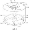
- Figure 4 illustrates a perspective view of the exemplary combustion chamber 100 in operation. While the chamber 100 is shown to be cylindrical, any shape having a central axis A may be implemented. The chamber 100, while shown as symmetrical about the axis A, may not necessarily be symmetrical. A vortex 118 is formed within the chamber 100. The vortex 118 may be formed, at least in part, by the air flow 148 from the air holes 120 and the fuel flow 150 (see Figure 5 ) from the fuel holes 122. This is explained in more detail below with respect to figures 6 and 7 . The vortex 118 may be proximal to the inlet end 104 and may maintain at least a portion of the product gases within the chamber 100 by creating recirculation flow and a bulk swirl within the chamber 100.
- air flow 148 may be received from the outlet end 102 at a first momentum.
- the fuel may be received at the inlet end 104 at a second momentum.
- the air flow may be at a greater momentum than that of the fuel flow.
- the air flow 148 may also be at a greater momentum that that of the central flow from the central injector 114.
- the air flow 148 may oppose the central flow 152 (see Figure 5 ) and fluid flow 150, forcing at least a portion of the product gases back towards the inlet end 104 to create a vortex 118 of product gases and be recirculated within the chamber 100.
- a portion of exhaust may leave the chamber 100 at the outlet opening 112.
- FIG. 5 illustrates an exemplary cross-sectional view of the exemplary combustion chamber 100.
- inlet ports 130 deliver air to the chamber 110.
- a plurality of fuel ports 138 deliver fuel at the inlet end 104 to the chamber.
- the fuel ports 138 are shown as fuel passages entering the wall 108 proximal to the inlet end 104.
- Exemplary fuel flows 150 are also shown. While the fuel flow 150 is shown as parallel to the wall 108, other exemplary fuel flows may be implemented. For example, the fuel may flow offset from the wall 108. Additionally or alternatively, fuel may flow parallel to the inlet end 104.
- Exemplary air flows 148 are also shown.
- the air flow 148 may angle such that the end or the tip of the air flow may be offset from the beginning of the air flow at the air holes 120. That is, air may not flow parallel to the central flow, but instead may be offset by a certain degree.
- each of the air flows 148 may form an azimuth-like air flow.
- each of the inlet port holes 132 may be angled at the same offset to form a continuous azimuthal flow throughout the chamber. In other example, the inlet port holes 132 may be angled by differing degrees. By angling the air flow 148, a swirling flow within the chamber 100 may be facilitated.
- the swirling flow may also be further facilitated by the central injector 114.
- the central injector 114 may deliver the pilot to the chamber, as well as at least one of fuel and air. This may create the central flow 152, which may in part be recycled into a recirculating flow (shown in Figure 6 .)
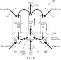
- Figure 6 illustrates an exemplary fluid flow diagram of the combustion chamber 100.
- the air holes 120/inlet port holes 132 and fuel holes 122/fuel port holes 140 may be configured to create air flow 148 and fuel flow 150, respectively.
- a central injector passing air and/or fuel 114 at an inlet opening 110 may be configured to create a central flow 152. Portions of the central flow 152 may exit the chamber 100 at the outlet opening 112. However, the remaining portion of the central flow 152 may be deflected by the air flow 148 to create the recirculation flow 154.
- the recirculation flow 154 may include both air and fuel and flow from the outlet end 102 towards the inlet end 104 where it may rejoin the vortex 118 of product gases.
- Figure 7 illustrates a perspective view of the exemplary combustion chamber 100 in operation when the fuel is delivered via equally spaced fuel ports 138.
- the fuel ports 138 may be configured as azimuthal jets configured to concurrently deliver reactant, e.g., fuel, to the chamber 100.
- the fuel ports 138 may be equally spaced around the chamber 100.
- Each fuel port 138 may be configured to supply fuel to a region of the chamber 100.
- Each region may be configured to supply at least a portion of product gases to the next region, thus creating a continuous supply of product gases 124 for the reaction at each fuel port 138.
- this vortex 118 may include a bulk swirl of product gases and reactant configured to partially recirculate the product gases within the chamber 100, forcing them to return towards the inlet end 104.
- While the fuel flow may be introduced normal to the wall 108, as shown in Figure 5 .
- the fuel flow may also be at an angle, as shown in Figure 7 .
- the fuel reactant
- the fuel may penetrate the vortex 118 created by the reverse flowing air jets to facilitate the creation of the azimuthal toroid flow of product gases 124.
- each fuel jet/port 138 will enter in proximity to the product gases 124 of the preceding reaction. Any number of fuel ports 138 may be used. With proper circulation, only one port 138 may be necessary. Additionally, three ports 138 may be contemplated and anywhere between approximately 4-12 ports 138 may arranged around the combustion chamber 100.
- the fuel flow 150 may be introduced through the fuel ports 138 (or fuel holes 122) with sufficient momentum to carry the fuel into the toriodal azimuthal vortex before ignition occurs. Additionally or alternatively, the air flow 148 may provide sufficient momentum to carry the fuel flow in a swirl and enhance mixing with the hot combustion gasses until ignition occurs. This may be facilitated by angled air holes 120 that provide a bulk swirl to the vortex 118.
- the described fluid flows may be applied to any reaction process that could benefit through product recirculation and/or reactant dilution in a limited volume example.
- sufficient dilution, mixing, and energy are achieved in addition to a stable highly-dilute combustion regime in the bulk of the combustion chamber by creating the azimuthal stabilization of the reaction.
Landscapes
- Engineering & Computer Science (AREA)
- Chemical & Material Sciences (AREA)
- Combustion & Propulsion (AREA)
- Mechanical Engineering (AREA)
- General Engineering & Computer Science (AREA)
Description
- The present disclosure relates to an improved combustion chamber of a gas turbine engine.
- Development for combustion of gas turbine engines may focus on reducing emissions and being able to burn a variety of fuel sources. Certain requirements for low emissions of nitrogen oxides (NOx) and carbon monoxide (CO) provide certain design constraints. Achieving low CO is generally linked with complete combustion and product gases being in thermodynamic equilibrium. Achieving low NOx is linked with low combustion temperatures and low residence times, which can be brought about through lean fuel-air ratios and/or dilution. Dilution of combustion gases may be achieved with exhaust gases, such as exhaust gas recirculation (EGR) and flue gas recirculation (FGR.) These conditions may result in incomplete combustion which in turn may lead to high CO output.
- To prevent incomplete combustion, traditional combustion systems are sized with an appropriate volume. However, this approach and with high dilution (EGR or FGR) may be limited by flammability and temperature limits. Thus, a combustion chamber configured to result in combustion with ultra-low NOx and CO output is needed.
- These and other objects are achieved by a combustion chamber according to the appended claims 1 and 9 and a by a method of creating a vortex within a combustion chamber according to the appended claim 17. Further detailed characteristics and advantages are described in the dependent claims.
-
EP 2 006 606 A1 andDE 10 2005 008 421 A1 - While the claims are not limited to a specific illustration, an appreciation of the various aspects is best gained through a discussion of various examples thereof. Referring now to the drawings, exemplary illustrations are shown in detail. Although the drawings represent the illustrations, the drawings are not necessarily to scale and certain features may be exaggerated to better illustrate and explain an innovative aspect of an example. Further, the exemplary illustrations described herein are not intended to be exhaustive or otherwise limiting or restricted to the precise form and configuration shown in the drawings and disclosed in the following detailed description. Exemplary illustrations are described in detail by referring to the drawings as follows:
-
FIG. 1 illustrates a schematic view of a gas turbine engine employing the improvements discussed herein; -
FIG. 2 illustrates a perspective view of an exemplary combustion chamber; -
FIG. 3 illustrates a perspective view of another exemplary combustion chamber; -
FIG. 4 illustrates a perspective view of the exemplary combustion chamber ofFig. 2 in operation; -
FIG. 5 illustrates an exemplary cross-sectional view of the exemplary combustion chamber; -
FIG. 6 illustrates an exemplary fluid flow diagram of the combustion chamber; and -
FIG. 7 illustrates a combustion chamber showing fluid flow paths. - Described herein is a combustion chamber configured to create a vortex within the chamber by mixing air from the outlet end of the chamber with fuel injected at an inlet end of the chamber. Due to the manner at which the air enters the outlet end of the chamber, the product gases created by the reaction of mixing the air and fuel is partially trapped, forcing a portion of them to return to the inlet end. Further, azimuthal reactant jets may be spaced within the chamber to provide reactant. These jets may be reverse-flowing swirling jets that provide a bulk fluid motion so that the product gases at one jet provides the reactant for the next. That is, each reaction is supported by a stream of product gases from the previous reaction. The created swirl, however, may not be sufficient to induce vortex breakdown, but simply be enough to provide a conical flow path. The embodiments described herein provide for a lean azimuthal flame (LEAF) combustor to achieve stable, highly diluted combustion. In order to provide for this configuration, the air flow entering the chamber at the outlet end may create an azimuthal flow. That is, the air flow may angle such that the end of the air flow may be offset from the air holes, as is described herein.
-
FIG. 1 illustrates agas turbine engine 10 which may be configured to provide general power generation. Theengine 10 may include a low pressure compressor, and intermediate compressor (not shown), and a high pressure compressor, 14 and 16, acombustor 18, and a high pressure turbine, an intermediate pressure turbine (not shown), and low pressure turbine, 20 and 22, respectively. Thehigh pressure compressor 16 is connected to afirst rotor shaft 24 while thelow pressure compressor 14 is connected to asecond rotor shaft 26. The intermediate compressor would be connected to the intermediate via a third rotor shaft. The shafts extend axially and are parallel to a longitudinal center line axis 28.Theengine 10 includes an improvedcombustion chamber 100, which incorporates the improved features disclosed herein. -
FIG. 2 illustrates a perspective view of anexemplary combustion chamber 100 of thecombustor 18. Thecombustion chamber 100 may facilitate the combination of fuel and air for combustion in a jet fuel engine or an industrial gas turbine. The fuel may be gaseous, liquid or solid, or any combination thereof. Common examples of gaseous fuels may be any one or combination of natural gas (composed of, but not limited to, methane and or ethane and or propane and or butane, pentane (and or the isomer variants), hydrogen, carbon monoxide, carbon dioxide, nitrogen, water, etc., and/or Syngas (composed of, but not limited to hydrogen, and or carbon monoxide, methane, carbon dioxide, nitrogen, water, etc.). Examples of liquid fuels may be any one or combination of alcohol, kerosene, diesel, etc. An example of solid fuel may be pulverized coal. The air may be an oxidant and may include a number of compositions from a variety of sources. The fuel and air may be premixed, or it may not be. Within thechamber 100, the fuel and air may combine and react. These reactions may facilitate combustion. The combined fuel and air may be referred to herein as 'product gases.' - The
combustion chamber 100 has a first surface, referred to hereinafter as anoutlet end 102, and a second surface, referred to hereinafter as aninlet end 104. The twoends wall 108 forming a cylinder-like chamber 100. Theinlet end 104 defines at least one inlet opening 110. Theoutlet end 102 defines at least one outlet opening 112 configured to allow exhaust products to exit thechamber 100. The exhaust may provide energy to a turbine (not shown). Each of theopenings respective ends - The
inlet opening 110 may be configured to receive a central injector 114 (as shown inFigure 4 .). Thecentral injector 114 may be configured to deliver a central reaction zone to thechamber 100. The central reaction zone may maintain the stability of thecombustion chamber 100. This may be done by providing a reaction for the chamber. A pilot may be included but is not necessary. The pilot may be used to ignite product gases and facilitate reactions within thechamber 100. Stabilization may occur by the pilot being continually lit. Additionally or alternatively, thecentral injector 114 may also deliver fuel and air to thechamber 100, as described herein. Theoutlet opening 112 is configured to allow gasses and exhaust to leave thecombustion chamber 100. While the axis A is shown as being generally located in the center of thechamber 100, in embodiments not being part of the present invention the exhaust and/orcentral injector chamber 100. - The
outlet end 102 defines a plurality of first holes, hereinafter referred to as air holes 120. These air holes 120 are configured to deliver air to the inside of thecombustion chamber 100 and facilitate the bulk fluid motion within thechamber 100. Theinlet end 104 defines a plurality of second holes, hereinafter referred to as fuel holes 122. These fuel holes 122 are configured to deliver premixed fuel to the inside of thecombustion chamber 100. The air holes 120 may be considered 'reverse' inlets because they oppose the general direction of the flow of exhaust through a central flow. The air flow from the air holes 120 may provide the bulk fluid motion. The air holes 120 may be frusto-conical or pyramid-like. Theholes 120 have an outer diameter and an inner diameter smaller than the outer diameter. Air flows into theholes 120 at an outer diameter and into thechamber 100 at the inner diameter. These frusto-conical and/or pyramid likeholes 120 may allow air to enter thechamber 100 at a higher momentum than if theholes 120 were in a cylindrical shape. Additionally or alternatively, the inner diameter of the air holes 120 may be larger than a diameter of the fuel holes 122. That is, more air may enter thechamber 100 than fuel. Additionally, air may enter thechamber 100 at a higher momentum than the fuel. The number ofair holes 120 may exceed the number offuel holes 122 allowing more air than fuel to enter thecombustion chamber 100. Further, it may not be necessary for the number ofair holes 120 to exceed that of the fuel holes 122 so long as more air is received at theoutlet end 102. In a lean system, as described herein, the air flow may have a much larger volume than the fuel flow. - The fuel and air introduced at the
inlet opening 110 may facilitate combustion within thechamber 100. This flow of fuel and air may also facilitate product gases flow from the inlet opening 110 to theoutlet opening 112. This is referred to hereinafter as central flow. This central flow may allow product gases to leave thechamber 100 through theoutlet opening 112. The air flow from the air holes 120 may have a greater flow than the center flow. This may cause portions of the product gases of the center flow to be pushed back towards theinlet end 104 and allow at least a portion of product gases to be maintained within thechamber 100. This is described in greater detail with respect toFigure 6 . Moreover, the fuel flow from the fuel holes 122, in combination with the downward airflow from the air holes 120, may create a vortex of product gases within thechamber 100. -
Figures 3 and5 illustrate anotherexemplary combustion chamber 100. In this exemplary configuration, a plurality ofinlet ports 130 extend radially inwardly towards theoutlet opening 112. Theinlet ports 130 form an air passage configured to deliver air from outside of thechamber 100 to the interior of thechamber 100 at theoutlet end 102. Eachinlet port 130 defines at least oneinlet port hole 132. Theseholes 132 are similar to the air holes 120 described above. The inlet port holes 132 deliver air at theoutlet end 102 of thechamber 100 to facilitate a vortex 118 (seeFigure 4 ) proximal to theinlet end 104 with azimuthal rotation and swirl. The inlet port holes 132 may have a frusto-conical shape, as explained above with regard to the air holes 120. -
Figure 4 illustrates a perspective view of theexemplary combustion chamber 100 in operation. While thechamber 100 is shown to be cylindrical, any shape having a central axis A may be implemented. Thechamber 100, while shown as symmetrical about the axis A, may not necessarily be symmetrical. Avortex 118 is formed within thechamber 100. Thevortex 118 may be formed, at least in part, by theair flow 148 from the air holes 120 and the fuel flow 150 (seeFigure 5 ) from the fuel holes 122. This is explained in more detail below with respect tofigures 6 and7 . Thevortex 118 may be proximal to theinlet end 104 and may maintain at least a portion of the product gases within thechamber 100 by creating recirculation flow and a bulk swirl within thechamber 100. In one example,air flow 148 may be received from theoutlet end 102 at a first momentum. The fuel may be received at theinlet end 104 at a second momentum. The air flow may be at a greater momentum than that of the fuel flow. Theair flow 148 may also be at a greater momentum that that of the central flow from thecentral injector 114. Thus, theair flow 148 may oppose the central flow 152 (seeFigure 5 ) andfluid flow 150, forcing at least a portion of the product gases back towards theinlet end 104 to create avortex 118 of product gases and be recirculated within thechamber 100. A portion of exhaust may leave thechamber 100 at theoutlet opening 112. -
Figure 5 illustrates an exemplary cross-sectional view of theexemplary combustion chamber 100. In this example,inlet ports 130 deliver air to thechamber 110. Additionally, a plurality offuel ports 138 deliver fuel at theinlet end 104 to the chamber. Thefuel ports 138 are shown as fuel passages entering thewall 108 proximal to theinlet end 104. Exemplary fuel flows 150 are also shown. While thefuel flow 150 is shown as parallel to thewall 108, other exemplary fuel flows may be implemented. For example, the fuel may flow offset from thewall 108. Additionally or alternatively, fuel may flow parallel to theinlet end 104. Exemplary air flows 148 are also shown. In this example, theair flow 148 may angle such that the end or the tip of the air flow may be offset from the beginning of the air flow at the air holes 120. That is, air may not flow parallel to the central flow, but instead may be offset by a certain degree. In the example shown, each of the air flows 148 may form an azimuth-like air flow. In one example, each of the inlet port holes 132 may be angled at the same offset to form a continuous azimuthal flow throughout the chamber. In other example, the inlet port holes 132 may be angled by differing degrees. By angling theair flow 148, a swirling flow within thechamber 100 may be facilitated. - Although the above example refers to the
inlet ports 130, the same offsets may be achieved by defining the air holes 120 in theoutlet end 102 as described with respect toFigures 2 and4 . - The swirling flow may also be further facilitated by the
central injector 114. Thecentral injector 114 may deliver the pilot to the chamber, as well as at least one of fuel and air. This may create thecentral flow 152, which may in part be recycled into a recirculating flow (shown inFigure 6 .) -
Figure 6 illustrates an exemplary fluid flow diagram of thecombustion chamber 100. As explained above, the air holes 120/inlet port holes 132 andfuel holes 122/fuel port holes 140 (seeFigure 5 ) may be configured to createair flow 148 andfuel flow 150, respectively. Additionally, a central injector passing air and/orfuel 114 at aninlet opening 110 may be configured to create acentral flow 152. Portions of thecentral flow 152 may exit thechamber 100 at theoutlet opening 112. However, the remaining portion of thecentral flow 152 may be deflected by theair flow 148 to create therecirculation flow 154. Therecirculation flow 154 may include both air and fuel and flow from theoutlet end 102 towards theinlet end 104 where it may rejoin thevortex 118 of product gases. -
Figure 7 illustrates a perspective view of theexemplary combustion chamber 100 in operation when the fuel is delivered via equally spacedfuel ports 138. Thefuel ports 138 may be configured as azimuthal jets configured to concurrently deliver reactant, e.g., fuel, to thechamber 100. Thefuel ports 138 may be equally spaced around thechamber 100. Eachfuel port 138 may be configured to supply fuel to a region of thechamber 100. Each region may be configured to supply at least a portion of product gases to the next region, thus creating a continuous supply ofproduct gases 124 for the reaction at eachfuel port 138. Additionally, thisvortex 118 may include a bulk swirl of product gases and reactant configured to partially recirculate the product gases within thechamber 100, forcing them to return towards theinlet end 104. - While the fuel flow may be introduced normal to the
wall 108, as shown inFigure 5 . The fuel flow may also be at an angle, as shown inFigure 7 . As explained, the fuel (reactant) may penetrate thevortex 118 created by the reverse flowing air jets to facilitate the creation of the azimuthal toroid flow ofproduct gases 124. Once combustion has initiated due to the pilot and the product gases, each fuel jet/port 138 will enter in proximity to theproduct gases 124 of the preceding reaction. Any number offuel ports 138 may be used. With proper circulation, only oneport 138 may be necessary. Additionally, threeports 138 may be contemplated and anywhere between approximately 4-12ports 138 may arranged around thecombustion chamber 100. - The
fuel flow 150 may be introduced through the fuel ports 138 (or fuel holes 122) with sufficient momentum to carry the fuel into the toriodal azimuthal vortex before ignition occurs. Additionally or alternatively, theair flow 148 may provide sufficient momentum to carry the fuel flow in a swirl and enhance mixing with the hot combustion gasses until ignition occurs. This may be facilitated byangled air holes 120 that provide a bulk swirl to thevortex 118. - Although the disclosure focusses on combustion chambers, the described fluid flows may be applied to any reaction process that could benefit through product recirculation and/or reactant dilution in a limited volume example. Through the above apparatus and methods, sufficient dilution, mixing, and energy are achieved in addition to a stable highly-dilute combustion regime in the bulk of the combustion chamber by creating the azimuthal stabilization of the reaction.
- By creating this vortex of product proximal to the inlet end, extremely high homogeneity of product composition and temperature is maintained throughout the chamber. Peak flame temperatures are also reduced and therefore minimize the thermal load on the walls and injector of the combustion chamber. Additionally, very low CO, NOx and UHC (unburned hydrocarbon) emissions are achieved. Further, the above system may operate with complete absence of the pilot flame. It may be used in a wide range of operations and has good fuel flexibility due to longer residence times and high rates of mixing.
Claims (20)
- A combustion chamber (100) comprising:a first surface (102) and a second surface (104) interconnected by a wall (108) forming said chamber (100);the first surface (102) defining a plurality of first openings (120) each first opening (120) of the plurality of first openings (120) having an outer diameter and an inner diameter smaller than the outer diameter, and wherein air is configured to pass from the outer diameter through the inner diameter into the chamber; andthe second surface (104) defining a plurality of second openings (122) configured to receive fuel,wherein air from the first openings (120) of the plurality of first openings (120) and fuel from the second openings (122) of the plurality of second openings (122) oppose each other to create a vortex of product proximal to the second surface (104),wherein the chamber (100) having a central axis (A), the first surface (102) defining at least one outlet opening (112) configured to allow exhaust products to exit the chamber (100) and the second surface (104) defining at least one inlet opening (110), and each of the at least one outlet opening (112) and the at least one inlet opening (110) are axially aligned along the central axis (A), wherein the plurality of first openings (120) and the plurality of second openings (122) are arranged on a circumference around the central axis (A).
- The combustion chamber (100) of claim 1, wherein the inner diameter of the first openings (120) is larger than a diameter of the second openings (122).
- The combustion chamber (100) of any one of claims 1-2, wherein the first openings (120) are offset from the wall (108).
- The combustion chamber (100) of any one of claims 1-3, wherein each of the first openings (120) are equally offset from the wall (108).
- The combustion chamber (100) of any one of claims 1-4, wherein the inlet opening (110) is configured to receive at least one of air and fuel to further create the air flow.
- The combustion chamber (100) of any one of claims 1-5, further comprising a pilot at the inlet opening (110).
- The combustion chamber (100) of any one of claims 1-6, wherein a number of first openings (120) is greater than a number of second openings (122).
- The combustion chamber (100) of any one of claims 1-7, wherein fuel flow from each of the second openings (122) is configured to react with at least a portion of the product within the vortex.
- A combustion chamber (100) comprising:a first surface (102) and a second surface (104) interconnected by a wall (108) forming a chamber (100) having a central axis (A), the first surface (102) defining an exhaust opening (112) and the second surface (104) defining a pilot opening (110), wherein the exhaust opening (112) and the pilot (110) opening align along the central axis (A) of the chamber (100);a plurality of inlet ports (130) arranged on an inside of the first surface (102), wherein each of the inlet ports (130) of the plurality of inlet ports (130) includes an inlet port hole (132), each inlet port hole (132) having an outer diameter and an inner diameter smaller than the outer diameter, air flows into each inlet port hole (132) at the outer diameter and into the chamber (100) at the inner diameter,each inlet port (130) of the plurality of inlet ports (130) extends radially inwardly towards the exhaust opening (112), each inlet port (130) being configured to deliver air to the chamber (100);a plurality of fuel ports (138) arranged on an inside of the second surface (104), wherein each of the fuel ports (138) of the plurality of fuel ports (138) extend radially inwardly from an edge of the second surface to deliver fuel to the chamber; andwherein air from inlet ports (130) and fuel from the fuel ports (138) oppose each other to create a vortex of product proximal to the second surface (102).
- The combustion chamber (100) of claim 9, wherein momentum of the air flow from the inlet ports (130) is greater than momentum of the fuel from the fuel ports (138).
- The combustion chamber (100) of any one of claims 9-10, wherein each of the inlet ports (130) define at least one first opening at their end to deliver air to the chamber (100).
- The combustion chamber (100) of claim 11, wherein the first openings (120) have an outer diameter and an inner diameter smaller than the outer diameter.
- The combustion chamber (100) of claim 12, wherein each of the first openings (120) azimuthal to the wall (108).
- The combustion chamber (100) of any one of claims 9-13, wherein a number of first inlet ports (130) is greater than a number of fuel ports (138).
- The combustion chamber (100) of any one of claims 9-14, wherein the fuel ports (138) are reverse flowing jets configured to react with at least a portion of the product within the vortex.
- The combustion chamber (100) of any one of claims 9-15, wherein the pilot opening (110) is configured to deliver at least one of fuel and air into the chamber (100) creating a central flow (152), wherein a portion of the central fluid flow exits the chamber at the exhaust opening (112) and the other portion is abutted by the air flow from the first side to create a recirculation flow surrounding the central flow.
- A method of creating the vortex within the combustion chamber (100) of any one of claims 1-8, comprising:receiving air flow at the first surface (102) of the combustion chamber at a first momentum, wherein the air flow is at an angle relative to the first surface (102); andreceiving fuel flow at the second opposite side (104) of the combustion chamber (100) at a second momentum, wherein the first momentum is greater than the second momentum and the conflicting fluid flows create a rotating vortex of product proximal to the second surface (104).
- The method of claim 17, further comprising: receiving a central flow (152) including at least one of fuel and air at a central injector (114) on the second surface (104), wherein the central flow is opposite the air flow from the first surface (102).
- The method of claim 18, wherein a portion of the central flow leaves the combustion chamber (100) at an exhaust opening (112) defined in the first surface (102).
- The method of 19, wherein the air flow from the first surface (102) is configured to collide with the central flow and direct the other portion of the central flow towards the second surface (104) creating a recirculation flow.
Applications Claiming Priority (2)
| Application Number | Priority Date | Filing Date | Title |
|---|---|---|---|
| US201361780835P | 2013-03-13 | 2013-03-13 | |
| PCT/US2013/073280 WO2014143239A1 (en) | 2013-03-13 | 2013-12-05 | Lean azimuthal flame combustor |
Publications (2)
| Publication Number | Publication Date |
|---|---|
| EP2971975A1 EP2971975A1 (en) | 2016-01-20 |
| EP2971975B1 true EP2971975B1 (en) | 2020-07-22 |
Family
ID=49877027
Family Applications (1)
| Application Number | Title | Priority Date | Filing Date |
|---|---|---|---|
| EP13811708.0A Active EP2971975B1 (en) | 2013-03-13 | 2013-12-05 | Lean azimuthal flame combustor |
Country Status (6)
| Country | Link |
|---|---|
| US (1) | US9618208B2 (en) |
| EP (1) | EP2971975B1 (en) |
| JP (1) | JP6203371B2 (en) |
| CN (1) | CN105164471B (en) |
| CA (1) | CA2902809C (en) |
| WO (1) | WO2014143239A1 (en) |
Families Citing this family (20)
| Publication number | Priority date | Publication date | Assignee | Title |
|---|---|---|---|---|
| JP6177187B2 (en) * | 2014-04-30 | 2017-08-09 | 三菱日立パワーシステムズ株式会社 | Gas turbine combustor, gas turbine, control apparatus and control method |
| US10094571B2 (en) | 2014-12-11 | 2018-10-09 | General Electric Company | Injector apparatus with reheat combustor and turbomachine |
| US10094570B2 (en) | 2014-12-11 | 2018-10-09 | General Electric Company | Injector apparatus and reheat combustor |
| US10094569B2 (en) | 2014-12-11 | 2018-10-09 | General Electric Company | Injecting apparatus with reheat combustor and turbomachine |
| DE102016117408B4 (en) * | 2016-09-15 | 2020-11-26 | Eberspächer Climate Control Systems GmbH | Combustion chamber assembly for a fuel-operated vehicle heater |
| CN106545887A (en) * | 2016-10-09 | 2017-03-29 | 上海交通大学 | A kind of swirl-flow premixed spray nozzle device of biogas |
| CN108019741A (en) * | 2017-12-10 | 2018-05-11 | 罗碧婉 | Spiral vortex type boiler furnace |
| CN108049964A (en) * | 2017-12-10 | 2018-05-18 | 罗碧婉 | Spiral vortex type automobile internal device |
| CN108036306A (en) * | 2017-12-10 | 2018-05-15 | 罗碧婉 | Spiral vortex type boiler smoke combustion chamber |
| CN108049963B (en) * | 2017-12-10 | 2019-08-16 | 吕诗林 | Spiral vortex type automobile gasoline combustion chamber |
| US11661907B2 (en) | 2018-10-11 | 2023-05-30 | Sierra Space Corporation | Vortex hybrid rocket motor |
| US11073114B2 (en) | 2018-12-12 | 2021-07-27 | General Electric Company | Fuel injector assembly for a heat engine |
| US11286884B2 (en) | 2018-12-12 | 2022-03-29 | General Electric Company | Combustion section and fuel injector assembly for a heat engine |
| US12060853B2 (en) | 2019-01-30 | 2024-08-13 | Laboratoire Reaction Dynamics Inc. | Rocket engine with integrated oxidizer catalyst in manifold and injector assembly |
| US11572851B2 (en) | 2019-06-21 | 2023-02-07 | Sierra Space Corporation | Reaction control vortex thruster system |
| AT523924B1 (en) * | 2020-10-01 | 2022-01-15 | Comb Bay One E U | Method and device for recursive sequential combustion |
| US20220333783A1 (en) * | 2021-03-07 | 2022-10-20 | CPS-Holding Limited | Hydrogen-Fueled Combustor for Gas Turbines |
| US11952967B2 (en) | 2021-08-19 | 2024-04-09 | Sierra Space Corporation | Liquid propellant injector for vortex hybrid rocket motor |
| US11879414B2 (en) | 2022-04-12 | 2024-01-23 | Sierra Space Corporation | Hybrid rocket oxidizer flow control system including regression rate sensors |
| WO2024254646A1 (en) * | 2023-06-16 | 2024-12-19 | InfigoLabs Pty Ltd | Combustor and pyrolysis component, assembly and related systems and methods, and calcination system and method |
Family Cites Families (36)
| Publication number | Priority date | Publication date | Assignee | Title |
|---|---|---|---|---|
| US2257982A (en) | 1937-08-23 | 1941-10-07 | Bbc Brown Boveri & Cie | Gas turbocompressor plant |
| FR2381911A1 (en) | 1977-02-25 | 1978-09-22 | Guidas | IMPROVED COMBUSTION CHAMBER ESPECIALLY FOR A GAS TURBINE |
| US5076779A (en) * | 1991-04-12 | 1991-12-31 | Union Carbide Industrial Gases Technology Corporation | Segregated zoning combustion |
| GB2273316B (en) | 1992-12-12 | 1996-02-28 | Rolls Royce Plc | Bleed valve control |
| US5746048A (en) * | 1994-09-16 | 1998-05-05 | Sundstrand Corporation | Combustor for a gas turbine engine |
| GB2311596B (en) | 1996-03-29 | 2000-07-12 | Europ Gas Turbines Ltd | Combustor for gas - or liquid - fuelled turbine |
| US6101808A (en) | 1998-05-29 | 2000-08-15 | Orbital Technologies Corporation | Cryogenic solid hybrid rocket engine and method of propelling a rocket |
| EP0982544B1 (en) | 1998-08-27 | 2003-06-18 | ALSTOM (Switzerland) Ltd | Burner arrangement for a gas turbine |
| US6298659B1 (en) | 1999-03-24 | 2001-10-09 | Orbital Technologies Corporation | Vortex flow field and apparatus and method for producing the same |
| US6601380B2 (en) | 1999-03-24 | 2003-08-05 | Orbital Technologies Corporation | Hybrid rocket engine and method of propelling a rocket |
| AU6522000A (en) | 1999-08-09 | 2001-03-05 | Technion Research & Development Foundation Ltd. | Novel design of adiabatic combustors |
| US6672862B2 (en) * | 2000-03-24 | 2004-01-06 | North American Manufacturing Company | Premix burner with integral mixers and supplementary burner system |
| US7003961B2 (en) | 2001-07-23 | 2006-02-28 | Ramgen Power Systems, Inc. | Trapped vortex combustor |
| CH695793A5 (en) | 2001-10-01 | 2006-08-31 | Alstom Technology Ltd | Combustion method, in particular for methods of generation of electric power and / or heat. |
| GB2399600B (en) | 2001-10-26 | 2005-12-14 | Alstom Technology Ltd | Gas turbine adapted to operate with a high exhaust gas recirculation rate and a method for operation thereof |
| US6929469B2 (en) * | 2002-02-28 | 2005-08-16 | North American Manufacturing Company | Burner apparatus |
| DE10217913B4 (en) | 2002-04-23 | 2004-10-07 | WS Wärmeprozesstechnik GmbH | Gas turbine with combustion chamber for flameless oxidation |
| US6735949B1 (en) * | 2002-06-11 | 2004-05-18 | General Electric Company | Gas turbine engine combustor can with trapped vortex cavity |
| GB2398863B (en) | 2003-01-31 | 2007-10-17 | Alstom | Combustion Chamber |
| DE10326720A1 (en) | 2003-06-06 | 2004-12-23 | Rolls-Royce Deutschland Ltd & Co Kg | Burner for a gas turbine combustor |
| FR2872887B1 (en) * | 2004-07-07 | 2006-09-08 | Inst Francais Du Petrole | HOMOGENEOUS COMBUSTION METHOD AND THERMAL GENERATOR USING SUCH A METHOD |
| DE102005008421A1 (en) * | 2005-02-24 | 2006-08-31 | Alstom Technology Ltd. | Combustion chamber for a gas turbine, at a power station, has an additional air jet to give a counter flow and increase the fuel/air recirculation within the combustion zone |
| WO2006094896A1 (en) | 2005-03-09 | 2006-09-14 | Alstom Technology Ltd | Burner and annular combustion chamber for flameless combustion |
| GB2429516B (en) | 2005-08-27 | 2010-12-29 | Siemens Ind Turbomachinery Ltd | An apparatus for modifying the content of a gaseous fuel |
| US20070119179A1 (en) * | 2005-11-30 | 2007-05-31 | Haynes Joel M | Opposed flow combustor |
| US7452513B2 (en) | 2006-09-02 | 2008-11-18 | Igor Matveev | Triple helical flow vortex reactor |
| EP1950494A1 (en) | 2007-01-29 | 2008-07-30 | Siemens Aktiengesellschaft | Combustion chamber for a gas turbine |
| EP2006606A1 (en) * | 2007-06-21 | 2008-12-24 | Siemens Aktiengesellschaft | Swirling-free stabilising of the flame of a premix burner |
| EP2116768B1 (en) | 2008-05-09 | 2016-07-27 | Alstom Technology Ltd | Burner |
| DE102008032265B4 (en) | 2008-07-09 | 2010-06-10 | Deutsches Zentrum für Luft- und Raumfahrt e.V. | incinerator |
| US8695350B2 (en) * | 2009-01-13 | 2014-04-15 | University Of Maryland | Fuel efficient ultra-low emission and improved pattern factor colorless distributed combustion for stationary and propulsion gas turbine applications |
| EP2427694A1 (en) * | 2009-05-06 | 2012-03-14 | Ramgen Power Systems, LLC | Vortex combustor for low nox emissions when burning lean premixed high hydrogen content fuel |
| US8355854B2 (en) | 2009-05-08 | 2013-01-15 | General Electric Company | Methods relating to gas turbine control and operation |
| US8667800B2 (en) | 2009-05-13 | 2014-03-11 | Delavan Inc. | Flameless combustion systems for gas turbine engines |
| EP2407652A1 (en) | 2010-07-15 | 2012-01-18 | Siemens Aktiengesellschaft | Gas turbine with a secondary air system and method for operating such a gas turbine |
| CN102797565B (en) * | 2011-05-26 | 2016-02-17 | 杜臣 | Vortex combined type heat engine |
-
2013
- 2013-12-05 EP EP13811708.0A patent/EP2971975B1/en active Active
- 2013-12-05 WO PCT/US2013/073280 patent/WO2014143239A1/en not_active Ceased
- 2013-12-05 JP JP2016500118A patent/JP6203371B2/en active Active
- 2013-12-05 CN CN201380074577.0A patent/CN105164471B/en active Active
- 2013-12-05 CA CA2902809A patent/CA2902809C/en active Active
- 2013-12-30 US US14/143,589 patent/US9618208B2/en active Active
Non-Patent Citations (1)
| Title |
|---|
| None * |
Also Published As
| Publication number | Publication date |
|---|---|
| WO2014143239A1 (en) | 2014-09-18 |
| CN105164471A (en) | 2015-12-16 |
| JP2016511388A (en) | 2016-04-14 |
| CA2902809A1 (en) | 2014-09-18 |
| EP2971975A1 (en) | 2016-01-20 |
| CN105164471B (en) | 2017-09-08 |
| CA2902809C (en) | 2018-01-23 |
| US9618208B2 (en) | 2017-04-11 |
| JP6203371B2 (en) | 2017-09-27 |
| US20140260305A1 (en) | 2014-09-18 |
Similar Documents
| Publication | Publication Date | Title |
|---|---|---|
| US9618208B2 (en) | Lean azimuthal flame combustor | |
| RU2747009C9 (en) | Gas turbine combustor | |
| EP3679300B1 (en) | Gas turbine combustor assembly with a trapped vortex feature and method of operating a gas turbine combustor | |
| US9534790B2 (en) | Fuel injector for supplying fuel to a combustor | |
| EP2163819B1 (en) | Gas turbine combustor | |
| US9562690B2 (en) | Swirler, fuel and air assembly and combustor | |
| US6360776B1 (en) | Apparatus for premixing in a gas turbine engine | |
| US20080083224A1 (en) | Method and apparatus for reducing gas turbine engine emissions | |
| JP6181997B2 (en) | Gas turbine combustor and method for supplying fuel and combustion air to a combustion chamber of a gas turbine combustor | |
| JP2012241982A (en) | Combustor | |
| US8596074B2 (en) | Gas turbine combustor | |
| EP4298382B1 (en) | Method of injecting hydrogen into a combustion chamber of a combustor of a gas turbine system | |
| EP2584267B1 (en) | Injector having multiple fuel pegs | |
| JP2005090884A (en) | Fuel injection valve for gas turbine and low NOx combustor | |
| CZ2011784A3 (en) | Low-emission combustion chamber, especially of small gas-turbine engines |
Legal Events
| Date | Code | Title | Description |
|---|---|---|---|
| PUAI | Public reference made under article 153(3) epc to a published international application that has entered the european phase |
Free format text: ORIGINAL CODE: 0009012 |
|
| 17P | Request for examination filed |
Effective date: 20150826 |
|
| AK | Designated contracting states |
Kind code of ref document: A1 Designated state(s): AL AT BE BG CH CY CZ DE DK EE ES FI FR GB GR HR HU IE IS IT LI LT LU LV MC MK MT NL NO PL PT RO RS SE SI SK SM TR |
|
| AX | Request for extension of the european patent |
Extension state: BA ME |
|
| RIN1 | Information on inventor provided before grant (corrected) |
Inventor name: MASTORAKOS, EPAMINONDAS Inventor name: BOURQUE, GILLES Inventor name: SIDEY, JENNIFER, A.M. Inventor name: HOBBS, JOSEPH, L. Inventor name: GORDON, ROBERT, L. |
|
| DAX | Request for extension of the european patent (deleted) | ||
| STAA | Information on the status of an ep patent application or granted ep patent |
Free format text: STATUS: EXAMINATION IS IN PROGRESS |
|
| 17Q | First examination report despatched |
Effective date: 20180706 |
|
| GRAP | Despatch of communication of intention to grant a patent |
Free format text: ORIGINAL CODE: EPIDOSNIGR1 |
|
| STAA | Information on the status of an ep patent application or granted ep patent |
Free format text: STATUS: GRANT OF PATENT IS INTENDED |
|
| INTG | Intention to grant announced |
Effective date: 20190611 |
|
| GRAS | Grant fee paid |
Free format text: ORIGINAL CODE: EPIDOSNIGR3 |
|
| GRAA | (expected) grant |
Free format text: ORIGINAL CODE: 0009210 |
|
| STAA | Information on the status of an ep patent application or granted ep patent |
Free format text: STATUS: THE PATENT HAS BEEN GRANTED |
|
| AK | Designated contracting states |
Kind code of ref document: B1 Designated state(s): AL AT BE BG CH CY CZ DE DK EE ES FI FR GB GR HR HU IE IS IT LI LT LU LV MC MK MT NL NO PL PT RO RS SE SI SK SM TR |
|
| REG | Reference to a national code |
Ref country code: GB Ref legal event code: FG4D |
|
| REG | Reference to a national code |
Ref country code: CH Ref legal event code: EP |
|
| REG | Reference to a national code |
Ref country code: DE Ref legal event code: R096 Ref document number: 602013070962 Country of ref document: DE |
|
| REG | Reference to a national code |
Ref country code: AT Ref legal event code: REF Ref document number: 1293745 Country of ref document: AT Kind code of ref document: T Effective date: 20200815 |
|
| REG | Reference to a national code |
Ref country code: IE Ref legal event code: FG4D |
|
| REG | Reference to a national code |
Ref country code: LT Ref legal event code: MG4D |
|
| REG | Reference to a national code |
Ref country code: AT Ref legal event code: MK05 Ref document number: 1293745 Country of ref document: AT Kind code of ref document: T Effective date: 20200722 |
|
| PG25 | Lapsed in a contracting state [announced via postgrant information from national office to epo] |
Ref country code: BG Free format text: LAPSE BECAUSE OF FAILURE TO SUBMIT A TRANSLATION OF THE DESCRIPTION OR TO PAY THE FEE WITHIN THE PRESCRIBED TIME-LIMIT Effective date: 20201022 Ref country code: PT Free format text: LAPSE BECAUSE OF FAILURE TO SUBMIT A TRANSLATION OF THE DESCRIPTION OR TO PAY THE FEE WITHIN THE PRESCRIBED TIME-LIMIT Effective date: 20201123 Ref country code: AT Free format text: LAPSE BECAUSE OF FAILURE TO SUBMIT A TRANSLATION OF THE DESCRIPTION OR TO PAY THE FEE WITHIN THE PRESCRIBED TIME-LIMIT Effective date: 20200722 Ref country code: LT Free format text: LAPSE BECAUSE OF FAILURE TO SUBMIT A TRANSLATION OF THE DESCRIPTION OR TO PAY THE FEE WITHIN THE PRESCRIBED TIME-LIMIT Effective date: 20200722 Ref country code: FI Free format text: LAPSE BECAUSE OF FAILURE TO SUBMIT A TRANSLATION OF THE DESCRIPTION OR TO PAY THE FEE WITHIN THE PRESCRIBED TIME-LIMIT Effective date: 20200722 Ref country code: SE Free format text: LAPSE BECAUSE OF FAILURE TO SUBMIT A TRANSLATION OF THE DESCRIPTION OR TO PAY THE FEE WITHIN THE PRESCRIBED TIME-LIMIT Effective date: 20200722 Ref country code: HR Free format text: LAPSE BECAUSE OF FAILURE TO SUBMIT A TRANSLATION OF THE DESCRIPTION OR TO PAY THE FEE WITHIN THE PRESCRIBED TIME-LIMIT Effective date: 20200722 Ref country code: GR Free format text: LAPSE BECAUSE OF FAILURE TO SUBMIT A TRANSLATION OF THE DESCRIPTION OR TO PAY THE FEE WITHIN THE PRESCRIBED TIME-LIMIT Effective date: 20201023 Ref country code: NO Free format text: LAPSE BECAUSE OF FAILURE TO SUBMIT A TRANSLATION OF THE DESCRIPTION OR TO PAY THE FEE WITHIN THE PRESCRIBED TIME-LIMIT Effective date: 20201022 Ref country code: ES Free format text: LAPSE BECAUSE OF FAILURE TO SUBMIT A TRANSLATION OF THE DESCRIPTION OR TO PAY THE FEE WITHIN THE PRESCRIBED TIME-LIMIT Effective date: 20200722 |
|
| PG25 | Lapsed in a contracting state [announced via postgrant information from national office to epo] |
Ref country code: IS Free format text: LAPSE BECAUSE OF FAILURE TO SUBMIT A TRANSLATION OF THE DESCRIPTION OR TO PAY THE FEE WITHIN THE PRESCRIBED TIME-LIMIT Effective date: 20201122 Ref country code: LV Free format text: LAPSE BECAUSE OF FAILURE TO SUBMIT A TRANSLATION OF THE DESCRIPTION OR TO PAY THE FEE WITHIN THE PRESCRIBED TIME-LIMIT Effective date: 20200722 Ref country code: PL Free format text: LAPSE BECAUSE OF FAILURE TO SUBMIT A TRANSLATION OF THE DESCRIPTION OR TO PAY THE FEE WITHIN THE PRESCRIBED TIME-LIMIT Effective date: 20200722 Ref country code: RS Free format text: LAPSE BECAUSE OF FAILURE TO SUBMIT A TRANSLATION OF THE DESCRIPTION OR TO PAY THE FEE WITHIN THE PRESCRIBED TIME-LIMIT Effective date: 20200722 |
|
| PG25 | Lapsed in a contracting state [announced via postgrant information from national office to epo] |
Ref country code: NL Free format text: LAPSE BECAUSE OF FAILURE TO SUBMIT A TRANSLATION OF THE DESCRIPTION OR TO PAY THE FEE WITHIN THE PRESCRIBED TIME-LIMIT Effective date: 20200722 |
|
| REG | Reference to a national code |
Ref country code: DE Ref legal event code: R097 Ref document number: 602013070962 Country of ref document: DE |
|
| PG25 | Lapsed in a contracting state [announced via postgrant information from national office to epo] |
Ref country code: RO Free format text: LAPSE BECAUSE OF FAILURE TO SUBMIT A TRANSLATION OF THE DESCRIPTION OR TO PAY THE FEE WITHIN THE PRESCRIBED TIME-LIMIT Effective date: 20200722 Ref country code: SM Free format text: LAPSE BECAUSE OF FAILURE TO SUBMIT A TRANSLATION OF THE DESCRIPTION OR TO PAY THE FEE WITHIN THE PRESCRIBED TIME-LIMIT Effective date: 20200722 Ref country code: CZ Free format text: LAPSE BECAUSE OF FAILURE TO SUBMIT A TRANSLATION OF THE DESCRIPTION OR TO PAY THE FEE WITHIN THE PRESCRIBED TIME-LIMIT Effective date: 20200722 Ref country code: EE Free format text: LAPSE BECAUSE OF FAILURE TO SUBMIT A TRANSLATION OF THE DESCRIPTION OR TO PAY THE FEE WITHIN THE PRESCRIBED TIME-LIMIT Effective date: 20200722 Ref country code: DK Free format text: LAPSE BECAUSE OF FAILURE TO SUBMIT A TRANSLATION OF THE DESCRIPTION OR TO PAY THE FEE WITHIN THE PRESCRIBED TIME-LIMIT Effective date: 20200722 Ref country code: IT Free format text: LAPSE BECAUSE OF FAILURE TO SUBMIT A TRANSLATION OF THE DESCRIPTION OR TO PAY THE FEE WITHIN THE PRESCRIBED TIME-LIMIT Effective date: 20200722 |
|
| PLBE | No opposition filed within time limit |
Free format text: ORIGINAL CODE: 0009261 |
|
| STAA | Information on the status of an ep patent application or granted ep patent |
Free format text: STATUS: NO OPPOSITION FILED WITHIN TIME LIMIT |
|
| PG25 | Lapsed in a contracting state [announced via postgrant information from national office to epo] |
Ref country code: AL Free format text: LAPSE BECAUSE OF FAILURE TO SUBMIT A TRANSLATION OF THE DESCRIPTION OR TO PAY THE FEE WITHIN THE PRESCRIBED TIME-LIMIT Effective date: 20200722 |
|
| 26N | No opposition filed |
Effective date: 20210423 |
|
| PG25 | Lapsed in a contracting state [announced via postgrant information from national office to epo] |
Ref country code: SK Free format text: LAPSE BECAUSE OF FAILURE TO SUBMIT A TRANSLATION OF THE DESCRIPTION OR TO PAY THE FEE WITHIN THE PRESCRIBED TIME-LIMIT Effective date: 20200722 |
|
| REG | Reference to a national code |
Ref country code: CH Ref legal event code: PL |
|
| PG25 | Lapsed in a contracting state [announced via postgrant information from national office to epo] |
Ref country code: SI Free format text: LAPSE BECAUSE OF FAILURE TO SUBMIT A TRANSLATION OF THE DESCRIPTION OR TO PAY THE FEE WITHIN THE PRESCRIBED TIME-LIMIT Effective date: 20200722 Ref country code: MC Free format text: LAPSE BECAUSE OF FAILURE TO SUBMIT A TRANSLATION OF THE DESCRIPTION OR TO PAY THE FEE WITHIN THE PRESCRIBED TIME-LIMIT Effective date: 20200722 |
|
| REG | Reference to a national code |
Ref country code: BE Ref legal event code: MM Effective date: 20201231 |
|
| REG | Reference to a national code |
Ref country code: NL Ref legal event code: MP Effective date: 20200722 |
|
| PG25 | Lapsed in a contracting state [announced via postgrant information from national office to epo] |
Ref country code: LU Free format text: LAPSE BECAUSE OF NON-PAYMENT OF DUE FEES Effective date: 20201205 Ref country code: IE Free format text: LAPSE BECAUSE OF NON-PAYMENT OF DUE FEES Effective date: 20201205 |
|
| PG25 | Lapsed in a contracting state [announced via postgrant information from national office to epo] |
Ref country code: CH Free format text: LAPSE BECAUSE OF NON-PAYMENT OF DUE FEES Effective date: 20201231 Ref country code: LI Free format text: LAPSE BECAUSE OF NON-PAYMENT OF DUE FEES Effective date: 20201231 |
|
| REG | Reference to a national code |
Ref country code: DE Ref legal event code: R082 Ref document number: 602013070962 Country of ref document: DE Representative=s name: ROTH, THOMAS, DIPL.-PHYS. DR., DE |
|
| PG25 | Lapsed in a contracting state [announced via postgrant information from national office to epo] |
Ref country code: TR Free format text: LAPSE BECAUSE OF FAILURE TO SUBMIT A TRANSLATION OF THE DESCRIPTION OR TO PAY THE FEE WITHIN THE PRESCRIBED TIME-LIMIT Effective date: 20200722 Ref country code: MT Free format text: LAPSE BECAUSE OF FAILURE TO SUBMIT A TRANSLATION OF THE DESCRIPTION OR TO PAY THE FEE WITHIN THE PRESCRIBED TIME-LIMIT Effective date: 20200722 Ref country code: CY Free format text: LAPSE BECAUSE OF FAILURE TO SUBMIT A TRANSLATION OF THE DESCRIPTION OR TO PAY THE FEE WITHIN THE PRESCRIBED TIME-LIMIT Effective date: 20200722 |
|
| PG25 | Lapsed in a contracting state [announced via postgrant information from national office to epo] |
Ref country code: MK Free format text: LAPSE BECAUSE OF FAILURE TO SUBMIT A TRANSLATION OF THE DESCRIPTION OR TO PAY THE FEE WITHIN THE PRESCRIBED TIME-LIMIT Effective date: 20200722 |
|
| PG25 | Lapsed in a contracting state [announced via postgrant information from national office to epo] |
Ref country code: BE Free format text: LAPSE BECAUSE OF NON-PAYMENT OF DUE FEES Effective date: 20201231 |
|
| REG | Reference to a national code |
Ref country code: DE Ref legal event code: R082 Ref document number: 602013070962 Country of ref document: DE Representative=s name: ROTH, THOMAS, DIPL.-PHYS. DR., DE |
|
| REG | Reference to a national code |
Ref country code: DE Ref legal event code: R081 Ref document number: 602013070962 Country of ref document: DE Owner name: INDUSTRIAL TURBINE COMPANY (UK) LTD., GB Free format text: FORMER OWNER: INDUSTRIAL TURBINE COMPANY (UK) LIMITED, FRIMLEY, GB |
|
| P01 | Opt-out of the competence of the unified patent court (upc) registered |
Effective date: 20231222 |
|
| PGFP | Annual fee paid to national office [announced via postgrant information from national office to epo] |
Ref country code: GB Payment date: 20251223 Year of fee payment: 13 |
|
| PGFP | Annual fee paid to national office [announced via postgrant information from national office to epo] |
Ref country code: FR Payment date: 20251223 Year of fee payment: 13 |
|
| PGFP | Annual fee paid to national office [announced via postgrant information from national office to epo] |
Ref country code: DE Payment date: 20251229 Year of fee payment: 13 |