EP2971743B1 - Rectangular stacked fluted filter cartridge - Google Patents
Rectangular stacked fluted filter cartridge Download PDFInfo
- Publication number
- EP2971743B1 EP2971743B1 EP14769120.8A EP14769120A EP2971743B1 EP 2971743 B1 EP2971743 B1 EP 2971743B1 EP 14769120 A EP14769120 A EP 14769120A EP 2971743 B1 EP2971743 B1 EP 2971743B1
- Authority
- EP
- European Patent Office
- Prior art keywords
- filter
- flow face
- housing
- filter cartridge
- media
- Prior art date
- Legal status (The legal status is an assumption and is not a legal conclusion. Google has not performed a legal analysis and makes no representation as to the accuracy of the status listed.)
- Active
Links
- 239000012530 fluid Substances 0.000 claims description 37
- 230000007246 mechanism Effects 0.000 claims description 16
- 238000000034 method Methods 0.000 claims description 15
- 238000011045 prefiltration Methods 0.000 description 28
- 239000000853 adhesive Substances 0.000 description 18
- 230000001070 adhesive effect Effects 0.000 description 18
- 238000007789 sealing Methods 0.000 description 15
- 239000000463 material Substances 0.000 description 12
- 239000011324 bead Substances 0.000 description 11
- 238000001914 filtration Methods 0.000 description 9
- 238000011144 upstream manufacturing Methods 0.000 description 7
- JOYRKODLDBILNP-UHFFFAOYSA-N Ethyl urethane Chemical compound CCOC(N)=O JOYRKODLDBILNP-UHFFFAOYSA-N 0.000 description 6
- 230000008878 coupling Effects 0.000 description 5
- 238000010168 coupling process Methods 0.000 description 5
- 238000005859 coupling reaction Methods 0.000 description 5
- 239000004033 plastic Substances 0.000 description 5
- 230000001681 protective effect Effects 0.000 description 4
- 230000000712 assembly Effects 0.000 description 3
- 238000000429 assembly Methods 0.000 description 3
- 239000000428 dust Substances 0.000 description 2
- 239000006260 foam Substances 0.000 description 2
- 230000006870 function Effects 0.000 description 2
- 239000002245 particle Substances 0.000 description 2
- 229920000728 polyester Polymers 0.000 description 2
- 239000011148 porous material Substances 0.000 description 2
- 239000000565 sealant Substances 0.000 description 2
- 229920002943 EPDM rubber Polymers 0.000 description 1
- 239000004593 Epoxy Substances 0.000 description 1
- 239000004831 Hot glue Substances 0.000 description 1
- 229920001944 Plastisol Polymers 0.000 description 1
- -1 SIKAFLEX® urethane Chemical compound 0.000 description 1
- 238000002485 combustion reaction Methods 0.000 description 1
- 239000000356 contaminant Substances 0.000 description 1
- 238000006073 displacement reaction Methods 0.000 description 1
- 239000000446 fuel Substances 0.000 description 1
- 230000005484 gravity Effects 0.000 description 1
- 238000003780 insertion Methods 0.000 description 1
- 230000037431 insertion Effects 0.000 description 1
- 238000009434 installation Methods 0.000 description 1
- 239000007788 liquid Substances 0.000 description 1
- 238000004519 manufacturing process Methods 0.000 description 1
- 150000002825 nitriles Chemical class 0.000 description 1
- 239000004999 plastisol Substances 0.000 description 1
- 238000005728 strengthening Methods 0.000 description 1
- 229920003051 synthetic elastomer Polymers 0.000 description 1
- 239000005061 synthetic rubber Substances 0.000 description 1
Images


Classifications
-
- B—PERFORMING OPERATIONS; TRANSPORTING
- B01—PHYSICAL OR CHEMICAL PROCESSES OR APPARATUS IN GENERAL
- B01D—SEPARATION
- B01D46/00—Filters or filtering processes specially modified for separating dispersed particles from gases or vapours
- B01D46/52—Particle separators, e.g. dust precipitators, using filters embodying folded corrugated or wound sheet material
- B01D46/521—Particle separators, e.g. dust precipitators, using filters embodying folded corrugated or wound sheet material using folded, pleated material
- B01D46/525—Particle separators, e.g. dust precipitators, using filters embodying folded corrugated or wound sheet material using folded, pleated material which comprises flutes
- B01D46/526—Particle separators, e.g. dust precipitators, using filters embodying folded corrugated or wound sheet material using folded, pleated material which comprises flutes in stacked arrangement
-
- B—PERFORMING OPERATIONS; TRANSPORTING
- B01—PHYSICAL OR CHEMICAL PROCESSES OR APPARATUS IN GENERAL
- B01D—SEPARATION
- B01D46/00—Filters or filtering processes specially modified for separating dispersed particles from gases or vapours
- B01D46/0002—Casings; Housings; Frame constructions
- B01D46/0005—Mounting of filtering elements within casings, housings or frames
-
- Y—GENERAL TAGGING OF NEW TECHNOLOGICAL DEVELOPMENTS; GENERAL TAGGING OF CROSS-SECTIONAL TECHNOLOGIES SPANNING OVER SEVERAL SECTIONS OF THE IPC; TECHNICAL SUBJECTS COVERED BY FORMER USPC CROSS-REFERENCE ART COLLECTIONS [XRACs] AND DIGESTS
- Y10—TECHNICAL SUBJECTS COVERED BY FORMER USPC
- Y10T—TECHNICAL SUBJECTS COVERED BY FORMER US CLASSIFICATION
- Y10T29/00—Metal working
- Y10T29/49—Method of mechanical manufacture
- Y10T29/49718—Repairing
- Y10T29/49721—Repairing with disassembling
- Y10T29/4973—Replacing of defective part
Definitions
- the present invention generally relates to fluid filtration, and more particularly to filter assemblies including filter housings and filter cartridges.
- Various systems require filtration of fluid prior to use of the fluid within the system.
- engines utilize air filtration systems for filtering air, the fluid, prior to using the air within the engine to combust a fuel.
- These filtration systems will typically utilize a housing that cooperates with a replaceable filter cartridge to filter the flowing fluid.
- the filter cartridge becomes spent, such as when it has become full with removed dust particulates from the flowing fluid, the filter cartridge can be removed from the filter housing.
- fluted filter media which as used herein will be broad enough to include, but not limited to gathered, corrugated and tapered, fluted filter media.
- the filter media stacked to form a block of filter media.
- US 7,625,419 B2 discloses an air filter arrangement with a filter cartridge which include a recessed first flow face and an opposite outwardly projecting second flow face which has a central apex, and a V-shaped flow face of the filter media is configured for receiving a protrusion.
- WO 2010/114906 A1 relates to a filter cartridge which includes a media pack which has first and second opposite flow faces and it is suggested to mount a seal member onto a seal support section.
- EP 1 712 266 A1 relates to an air filter element which has a sealing ring which is welded, glued, extruded or fused on to its base.
- the filter assembly includes a filter housing.
- the filter housing defines an internal cavity, an inlet, and an outlet.
- the filter assembly includes a filter cartridge.
- the filter cartridge includes a stack of filter media.
- the stack of filter media includes an inlet flow face and an outlet flow face.
- the filter cartridge includes a frame coupled to the filter media. At least a portion of the filter cartridge is located within the internal cavity of the filter housing.
- the frame member defines an opening through which fluid may be directed to the inlet flow face of the filter media.
- the frame member includes a top surface.
- the inlet flow face is recessed below the top surface of the frame member. This may receive a projection from a housing.
- An advantage of this design is that a simple rectangular stack (including substacks if desired) can be used with the media pack having a flat inlet face. Complex fluted media packs therefore need not be formed and fixture and tooling manufacture for the same are avoided.
- a projecting portion of the housing projects into the opening defined by the frame member.
- the frame member surrounds the projecting portion of the housing and provides clearance due to the inlet flow face being recessed below the top surface of the frame member.
- the frame includes a first leg and a second leg.
- the first and second legs are located on opposite sides of the opening.
- the filter cartridge is located between the first leg and the second leg.
- the frame includes a rectangular top portion extending around the opening and defines a larger perimeter than the stack.
- the filter assembly also including a sealing member coupled to the top portion outside the legs and which extends around the opening.
- the sealing member is configured to seal with the filter housing to prevent fluid flow from bypassing the filter cartridge when the filter cartridge is installed in the filter housing.
- the sealing member is spaced above the inlet flow face.
- the filter cartridge includes a first end cap sealing one side of the filter media and overlapping with the frame member.
- the filter cartridge includes a second end cap sealing another side opposite the one side of the filter media. The second end cap overlapping with the frame member.
- the frame includes a plurality of ribs extending across the opening and below the top surface of the frame.
- the ribs run across and over the inlet flow face of the filter cartridge.
- the ribs may be recessed from the top surface of the frame member.
- the filter housing includes a first wall and a second wall.
- the first wall includes a first portion and a second portion.
- the second wall includes a first portion and a second portion.
- the first portion of the first wall and the first portion of the second wall are generally parallel.
- the second portion of the first wall and the second portion of the second wall converge towards one another proximate the outlet.
- the outlet flow face is flat.
- the filter cartridge has a guide mechanism projecting from the outlet flow face to engage the first and second portions.
- the outlet flow face of the filter media is located between the first portion of the first wall and the first portion of the second wall when the filter cartridge is installed in the filter housing.
- the guide mechanism includes converging blades projecting from opposing sides of the stack and into a region between the second portions.
- the stack of filter media includes a first side and a second side opposite the first side.
- the first and second sides extend generally perpendicular to the inlet and outlet flow faces and generally parallel to one another.
- the frame member defines a first channel proximate the first side and a second channel proximate the second side.
- the filter cartridge further includes a first end wall extending generally over the first side of the filter media.
- the first end wall includes a central portion and an outer wall portion extending generally perpendicularly to the central portion.
- the outer wall portion includes an upper portion configured to be located in the first channel of the frame member.
- the filter cartridge includes a second end wall extending generally over the second side of the filter media.
- the second end wall includes a central portion and an outer wall portion extending generally perpendicularly to the central portion.
- the outer wall portion of the second end wall includes an upper portion configured to be located in the second channel of the frame member.
- the filter assembly includes a filter housing.
- the filter housing defines an internal cavity, an inlet, and an outlet.
- the filter housing includes sidewalls proximate the outlet extending inwardly toward one another.
- the method includes providing a filter cartridge.
- the filter cartridge includes a fluted filter media and a frame member.
- the fluted filter media has an inlet flow face and an outlet flow face.
- the flutes of the fluted filter media extend from the inlet flow face to the outlet flow face.
- the outlet flow face is generally planar.
- the frame member includes a top portion having a top surface. The top portion extends from a first end to a second end.
- the top portion defines a central opening.
- the frame member is coupled to the fluted filter media such that fluid may be directed through the central opening to the inlet flow face of the filter media.
- the inlet flow face of the filter media is recessed below the top surface of the top portion. The method includes locating the filter cartridge in the internal cavity of the filter housing.
- the sidewalls of the filter housing include a first section where the sidewalls extend generally parallel to one another.
- the outlet flow face of the filter media is located between the first section of the sidewalls when the filter cartridge is located in the internal cavity of the filter housing.
- the method includes removing a filter cartridge including removing a media pack arrangement with filter media having first and second opposite flow faces.
- the media pack arrangement has a first recessed central region in one of the flow faces prior to locating the filter cartridge in the internal cavity of the filter housing.
- the filter cartridge further includes a seal member coupled to the frame member.
- the step of locating the filter cartridge in the internal cavity of the filter housing includes locating the seal against the filter housing to prevent contaminated fluid from passing into the filter housing.
- the filter cartridge includes filter media.
- the filter media includes a generally rectangular inlet flow face, an outlet flow face, and opposite first and second and opposite third and fourth sides extending from the inlet flow face to the outlet flow face.
- the first, second, third, and fourth sides each extend generally perpendicularly to the inlet flow face and the outlet flow face.
- the first side extends along a first plane.
- the second side extends along a second plane.
- the third side extends along a third plane.
- the fourth side extends along a fourth plane.
- the filter cartridge includes a frame member coupled to the filter media.
- the frame member defines a generally rectangular opening through which fluid may pass to the inlet flow face.
- the frame member includes a top portion and first and second legs spaced apart from one another.
- the first leg is coupled to the first side of the filter media.
- the second leg is coupled to the second side of the filter media.
- the filter cartridge includes a first end cap sealing the third side of the filter media. The first end cap overlaps with the first leg and the second leg in at least one direction parallel to either the first, third, or fourth planes.
- the filter cartridge includes a second end cap. The second end cap seals the fourth side of the filter media. The second end cap overlaps with the first leg and the second leg in at least one direction parallel to either the second, third, or fourth planes.
- the first end cap overlaps with the first leg and the second leg in a direction parallel to the first, third, and fourth planes.
- the second end cap overlaps with the first leg and the second leg in a direction parallel to the second, third, and fourth planes.
- the filter cartridge includes a seal extends under and around the top portion of the frame.
- the seal is configured to be located against a filter housing to prevent contaminated fluid from passing into the filter housing.
- the filter cartridge includes a stack of sheets of fluted filter media configured in a generally rectangular block having an inlet flow face and an outlet flow face.
- the filter cartridge also includes a frame coupled to the block of fluted filter media.
- the frame includes a top portion extending around and upwardly from the inlet flow face.
- the frame includes a pair of legs extending down toward the outlet flow face of the filter media.
- the frame defines a generally rectangular opening through which fluid may pass to the inlet flow face of the filter media.
- the top portion of the frame extends outwardly away from the filter media.
- the filter cartridge includes a seal member.
- the seal member extends around the filter media. The seal member is coupled to the portion of the top portion of the frame extending outwardly away from the filter media.
- the outlet flow face and the inlet flow face are each generally planar.
- the frame includes a connection portion extending between the top portion and the legs.
- the connection portion defines a pair of channels.
- the filter cartridge includes first and second end walls. Each end wall is configured to couple and/or is operably coupled to the filter media and to interface with one of the channels defined by the connection portion of the frame.
- the seal member is a foam pad prefilter.
- the frame member has a top surface.
- the inlet flow face of the filter media is recessed below the top surface of the frame member.
- a filter cartridge is disclosed herein.
- the filter cartridge includes a stack of sheets of fluted filter media configured in a generally rectangular block having an inlet flow face and an outlet flow face.
- a prefilter may be located upstream of the inlet flow face.
- a frame is coupled to the block of fluted filter media.
- the frame includes a top portion extending around and upwardly from the inlet flow face and the prefilter.
- a pair of legs extends past the prefilter and down toward the outlet flow face of the filter media.
- the frame defines a generally rectangular opening through which fluid may pass to the prefilter.
- the top portion of the frame extends outwardly away from the filter media.
- the prefilter the inlet flow face are recessed below a top surface of the frame.
- the frame includes ribs extending across the generally rectangular opening.
- the prefilter is located between the ribs and the inlet flow face.
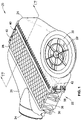
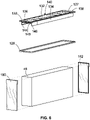
- FIG. 1 illustrates a filter assembly 20 according to a first embodiment of the present invention.
- the filter assembly 20 is generally configured for removing contaminants and particulates from within a flowing fluid stream, such as an air stream.
- the air stream may be used for supplying air to an engine such as an internal combustion engine or turbine.
- embodiments of filter assemblies can be used for alternative systems, as well as for filtering other fluids, such as liquids.
- embodiments of filter assemblies include a housing and a filter cartridge. When the filter cartridge is spent, it is removed from the housing and replaced.
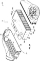
- the filter assembly 20 includes a housing 22 and a filter cartridge 23 (not illustrated in FIG. 1 , see FIG. 2 ) internally received into the housing 22.
- the housing 22 includes an inlet portion 24 and an outlet portion 26.
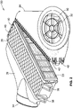
- the inlet portion 24 and the outlet portion 26 are separable from one another (see, e.g., FIG. 2 ).
- the outlet portion 26 includes a body section 28 into which the filter cartridge 23 is located during installation.
- the inlet portion 24 includes an inlet adapter 30 with an inlet aperture 32 therethrough.
- air to be filtered passes through the inlet aperture 32 to the interior of the housing 22.
- the adaptor 30 is configured to receive a bellows or other mechanism inside of an engine compartment of a vehicle, e.g., a truck, etc.
- the adapter 30 may be a preformed, plastic part.
- unfiltered air passes through the inlet aperture 32, through the inlet portion 24 and toward the outlet portion 26 with the air passing through the filter cartridge 23 to filter the air.
- the filtered air exits the filter assembly 20 through an outlet 34.
- the outlet portion 26 includes a rib pattern portion 36.
- the rib pattern portion 36 may provide strengthening of the surface of the outlet portion 26.
- the opposite side of the outlet portion 26 (not illustrated in FIG. 1 ) also includes a rib pattern portion.
- the outlet portion 26 provides mounting posts 38 and mounting brackets 40 configured to mount the housing 22, e.g., in a vehicle.
- the outlet portion 26, upon mounting, is fixed in place and is not movable with respect to the mounting, e.g., with respect to the vehicle, without dismounting the housing 22, while the inlet portion 24 is removable to provide access to the interior of the housing 22.
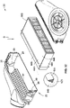
- Bolts 42 are configured to secure the inlet portion 24 to the outlet portion 26, e.g., to nut plates of the outlet portion 26. In other embodiments, other suitable fasteners and/or coupling mechanisms may be used. When the inlet portion 24 is to be removed from the outlet portion 26, the bolts 42 may be loosened or removed to allow the inlet portion 24 to be moved away from the outlet portion 26, as is illustrated in FIG. 2 .
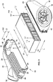
- the housing 22 includes a releasable hinge configured to allow pivotal displacement of the inlet portion 24 relative to the outlet portion 26 (as illustrated in FIG. 2 ) and detachment of the inlet portion 24 from the outlet portion 26 (as illustrated in FIG. 3 ).
- the filter cartridge 23 may be removed from or located within the filter housing 22.
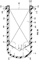
- a portion of the body section 28 is shown cut away to illustrate interior features of the housing 22. Extending inwardly from each of the sidewalls 29 of the body section 28 is an angular support feature 31 (only one support feature 31 visible in FIG. 3 ).
- the support feature 31 includes first and second support walls 33 and 35. The support walls 33 and 35 extend angularly downwardly away from the inlet portion 24 and toward one another generally towards an apex or junction region.
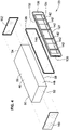
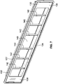
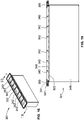
- FIG. 4 illustrates an exploded view of an embodiment of a filter cartridge 23.
- the filter cartridge 23 includes a stack of filter media 46. As illustrated in FIG. 4 , the stack of filter media 46 is configured in a generally rectangular block.
- the filter media 46 includes a flat inlet flow face 48 and a flat outlet flow face 50. As such, no offsetting or complex configuration of the media is needed. Instead, a simple rectangular stack can be used.
- the inlet and outlet flow faces 48 and 50 are generally parallel to one another and generally perpendicular to the direction of fluid flow. Each of the inlet flow face 48 and the outlet flow face 50 is generally planar.
- the filter media 46 extends from a first end 52 to a second end 54 in a direction generally perpendicular to the direction of fluid flow and perpendicular to the inlet 48 and outlet 50 flow faces and from a first sidewall 56 to a second sidewall 58.
- the inlet and outlet flow faces 48 and 50 are generally flat and extend generally perpendicular to the sidewalls 56 and 58 and ends 52 and 54.
- the filter media 46 is preferably fluted media.
- the fluted media is corrugated media.
- the flutes of the fluted media are formed by folding.
- the fluted media may be formed by any suitable method or mechanism.
- the filter media may be any other suitable type of media.
- the filter media 46 may include a plurality of inlet flutes and plurality of outlet flutes. The inlet flutes are open proximate the inlet flow face 48 and sealed proximate the outlet flow face 50, e.g., sealed with a bead of adhesive, etc.
- the outlet flutes are sealed proximate the inlet flow face 48, e.g., sealed with a bead of adhesive, etc., and open proximate the outlet flow face 50.
- a stack of fluted media can be accomplished in accordance with U.S. Patent No. 5,820,646 .
- the stack of filter media 46 includes a first stack of filter media 60 and a second stack of filter media 62.
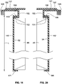
- the first and second stacks 60 and 62 each include a plurality of generally rectangular sheets 66 and 68 of fluted media (see FIGS. 20 and 21 ).
- the generally rectangular peripheries of the sheets 66 and 68 are aligned to form rectangular stacks with the opposite sides 70, 72 and 74, 76 of the stacks 60 and 62 being generally parallel with one another and generally perpendicular to the upper surface 78 of the first stack 60 and the lower surface 80 of the second stack 62.
- each of the sheets 66 of the first stack 60 includes a backing sheet 82 and a fluted sheet 84.
- the flutes project in a generally wave-like pattern.
- a sealing bead between the fluted sheet 84 and the backing sheet 82 seals one end of alternating and/or adjacent ones of the flutes.
- a sealing bead between the backing sheet 82 and a fluted sheet of another sheet 66 seals one end of alternating and/or adjacent flutes.
- the first stack 60 includes adjacent flutes having alternating first closed ends and second closed ends to provide for substantially straight through flow of the fluid between the upstream flow and the downstream flow. With this arrangement, the fluid to be filtered must pass through the filter media trapping dust carried thereby, and then pass into an adjacent flute open at the outlet end for exit.
- the sheets 66 are stacked in the same orientation with the first, generally flat sides 82 of the sheets 66 facing upwardly. In one embodiment, the sheets 66 are coupled together to form the first stack 60. The sheets 66 are coupled together with adhesive.
- Forming the filter media 46 with a first stack 60 and a second stack 62 coupled together with adhesive may add strength to the filter media 46 and may prevent telescoping of the stack of filter media 46, e.g., movement of the sheets 66 and 68 relative to one another, etc.
- a single stack of filter media may be used.
- each of the sheets 68 of the second stack 62 includes a backing sheet 86 and a fluted sheet 88.
- the flutes project in a generally wave-like pattern.
- a sealing bead between the fluted sheet 88 and the backing sheet 86 seals one end of alternating ones of the flutes.
- a sealing bead between the backing sheet 86 a fluted sheet of another sheet 68 seals one end of alternating flutes.
- the second stack 62 includes adjacent flutes having alternating first closed ends and second closed ends to provide for substantially straight through flow of the fluid between the upstream end and the downstream end, with flow having to pass through either one of the backing sheets or fluted sheets.
- the sheets 68 are stacked in the same orientation with the backing sheet 86 of the sheets 68 facing downwardly.
- the sheets 68 may be coupled together to form the second stack 62.
- the sheets 68 may be coupled together with adhesive.
- the first stack 60 and the second stack 62 are coupled together to form the stack of filter media 46.
- the first stack 60 has an inlet flow face 90.
- the inlet flow face 90 is generally perpendicular to the opposite sides 70 and 72 of the first stack 60.
- the inlet flow face 90 is also generally perpendicular to the upper surface 78 of the first stack 60.
- the second stack 62 also has an inlet flow face 92.
- the inlet flow face 92 is generally perpendicular to the opposite sides 74 and 76 of the second stack 62.
- the inlet flow face 92 is also generally perpendicular to the lower surface 80 of the second stack 62.
- the inlet flow faces 90 and 92 together form the combined flat or overall inlet flow face 48 of the stack of filter media 46 (see FIG. 4 ), when the stacks 60 and 62 are coupled together to form the stack of filter media 46.
- the side 70 of the first stack 60 and the side 74 of the second stack 62 together form the first end 52 of the stack of filter media 46.
- the side 72 of the first stack 60 and the side 76 of the second stack 62 together form the second end 54 of the stack of filter media 46.
- the sides 52 and 54 are generally parallel to one another and generally perpendicular to the inlet 48 and outlet 50 flow faces.
- the stack of filter media 46 includes a single stack of filter media 65.
- the single stack of filter media 65 includes a plurality of generally rectangular sheets 67 of fluted media (see FIG. 26 ). The generally rectangular peripheries of the sheets 67 are aligned to form the rectangular stack of filter media 46.
- FIG. 26 illustrates one embodiment of a sheet 67 of filter media.
- a portion of a layer of double-faced permeable fluted filter media 67 is illustrated.
- the sheet 67 includes flutes 69 that form a corrugated-type material.
- the flutes 69 are formed by a center fluting sheet 75 formed into peaks 71 and troughs 73 between a facing sheets 77.
- the peaks 71 and troughs 73 divide the flutes into an upper row and a lower row.
- the upper flutes form flute chambers 81 closed at the downstream end, while upstream closed end flutes 79 are the lower row of flute chambers.
- the fluted chambers 79 are closed by a first end bead 83 filling a portion of the upstream end of the flute between the fluting sheet 75 and the lower facing sheet 77.
- a second end bead 85 closes the downstream end of alternating flutes 81.
- Adhesive tacks 87 connect the peaks 71 and troughs 73 of the flutes 69 to the facing sheets 77.
- the adhesive of the tacks 87 is placed only at the apexes of the peaks 71 and troughs 73, rather than as a continuous bead, as shown in FIG. 26 .
- the minimal amount of adhesive keeps the chambers of the flutes open to accept increased fluid flow.
- the flutes 69 and end beads 83 and 85 may provide a filter cartridge which is structurally self-supporting.
- unfiltered fluid When filtering, unfiltered fluid enters the flute chambers 81 which have their upstream ends open as indicated by the shaded arrows. Upon entering the flute chambers 81, the unfiltered fluid flow is closed off by the second end bead 85. Therefore, the fluid is forced to proceed through one of the fluting sheets 75 or face sheets 77.
- a protective wrap 64 is coupled to and generally covers one side 78 of the first stack 60.
- the wrap 64 may be a sheet of paper material or plastic material.
- another wrap 64' is coupled to and generally covers an opposite side 80 of the second stack 62.
- the first end 52, the second end 54, the first sidewall 56, and the second sidewall 58 of the stack of filter media 46 are covered with a protective outer wrapper, e.g., the stack of filter media 46 is wrapped with an outer wrapper extending around the first end 52, the first sidewall 56, the second end 54, and the second sidewall 58 of the stack of filter media 46.
- the outer wrapper does not extend over the inlet flow face 48 or the outlet flow face 50 of the filter media 46.
- the stack of media 46 is deep pleated media.
- the stack of media 46 may extend a depth between the inlet flow face 48 and the outlet flow face 50 of at least approximately 6 inches; and the stack of media 46 may extend a length between the first end 52 and the second end 54 of between approximately 12 inches to approximately 36 inches; and the stack of media may extend a width between the first sidewall 56 and the second sidewall 58 of between approximately three inches and approximately nine inches.
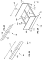
- the first guide 94 includes a first wall portion 98 and a second angular wall portion 100 extending from the first wall portion 98.
- the first wall portion 98 extends generally along a first plane, while the second angular wall portion 100 extends generally along a second plane non-parallel and non-coplanar with the first plane.
- the first wall portion 98 and the second angular wall portion 100 preferably extend generally the same length. In another embodiment, the first wall portion 98 extends a length shorter than the second angular wall portion 100.
- the first wall portion 98 is coupled to the wrap 64' proximate the outlet flow face 50, coupling the first guide 94 to the stack of media 46.
- the first wall portion 94 extends generally parallel to the lower surface 80 of the second stack 62.
- the second angular wall portion 100 extends non-parallel to the lower surface 80 of the second stack 62 forming an angle ⁇ 1 with the plane along which the first wall portion 98 extends, with the angle ⁇ 1 is less than 90°.
- the first guide 94 extends along the lower surface 80 of the second stack 62 from a location proximate the side 74 of the second stack 62 to a location proximate the side 76 of the second stack 62.
- the second guide 96 includes a first wall portion 102 and a second angular wall portion 104 extending from the first wall portion 102.
- the first wall portion 102 extends generally along a first plane, while the second angular wall portion 104 extends generally along a second plane non-parallel and non-coplanar with the first plane.
- the first wall portion 102 and the second angular wall portion 140 preferably extend generally the same length.
- the first wall portion 102 extends a length shorter than the second angular wall portion 104.
- the first wall portion 102 can be coupled to the wrap 64, proximate the outlet flow face 50 of the media 46 coupling the second guide 96 to the stack of media 46.
- the first wall portion 102 extends generally parallel to the upper surface 78 of the first stack 60.
- the second angular wall portion 104 extends non-parallel to the upper surface 78 of the first stack 60 forming an angle ⁇ 2 with the plane along which the first wall portion 102 extends, with the angle ⁇ 2 being less than 90°.
- the second guide 96 extends along the upper surface 78 of the first stack 60 from a location proximate the side 70 of the first stack 60 to a location proximate the side 72 of the first stack 60.
- the first guide 94 and the second guide 96 are generally the same length and are aligned on opposite sides of the stack of media 46.
- the guides 94 and 96 may provide for guidance of the filter cartridge 23 when the filter cartridge 23 is being located in the housing 22, as will be further discussed below.
- the guide 106 includes a first guide portion 108, a second guide portion 110 spaced apart from the first guide portion 108.
- the first guide portion 108 includes a first wall portion 112 and a second angular wall portion 114 extending downwardly from the first wall portion 112.
- the first wall portion 112 extends along a first plane, while the second angular wall portion 114 extends along a second plane non-parallel to and non-co-planar with the first plane.
- the second guide portion 110 includes a first wall portion 116 generally parallel with the first wall portion 112 and a second angular wall portion 118 extending downwardly from the first wall portion 116.
- the first wall portion 116 extends along a first plane, while the second angular wall portion 118 extends along a second plane non-parallel to and non-co-planar with the first plane.
- the guide 106 includes a connecting portion, illustrated in FIG. 24 as a plurality of bridges in the form of posts 120, 122, and 124, extending between the first guide portion 108 and the second guide portion 110.
- the post 120 extends proximate a first end of the first guide portion 108 from the first guide portion 108, proximate the location where the first wall portion 112 and the second angular wall portion 114 meet, to the second guide portion 110, proximate the location where the first wall portion 116 and the second wall portion 118 meet.
- the post 122 extends generally parallel to the post 120 between the post 120 and the post 124, from the first guide portion 108, proximate the location where the first wall portion 112 and the second angular wall portion 114 meet, to the second guide portion 110, proximate the location where the first wall portion first wall portion 116 and the second wall portion 118 meet.
- the post 124 extends proximate a second end of the first guide portion 108 opposite the first end of the first guide portion from the first guide portion 108, proximate the location where the first wall portion 112 and the second angular wall portion 114 meet, to the second guide portion 110, proximate the location where the first wall portion 116 and the second wall portion 118 meet.
- the first wall portion 112 of the first guide portion 108, the first wall portion 116 of the second guide portion 110 and the posts 120, 122, and 124 define a channel 126 configured to receive the outlet flow face 50 of the filter media 46.
- the first wall portion 112 is configured to be coupled to the first sidewall 56 of the filter media 46 and the first wall portion 116 is coupled to the second sidewall 58 of the filter media 46.
- the second angular wall portions 114 and 118 may provide for guidance for the filter cartridge when the filter cartridge is being located in the housing 22, as will be further discussed below.
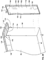
- the filter cartridge 23 includes a frame, illustrated in FIG. 4 as an end frame 127.
- the filter cartridge 23 also includes a seal 128.
- the end frame 127 includes a top portion 130 that is configured to be placed over the inlet face of the fluted media stack.
- the frame 127 may include first and second generally parallel sides 132 and 134 and third and fourth sides 136 and 138 generally parallel to one another and generally perpendicular to sides 132 and 134.
- the top portion 130 extends around a generally rectangular open center 140 through which fluid flows to the inlet flow face 48 (see FIG. 4 ) of the filter media 46.
- the ribs 142 extend from the top surface of the end frame 127 downwardly to the inlet flow face 48 of the filter media 46.
- the ribs 142 provide support and also protect the inlet flow face.
- the end frame 127 also includes a first leg 144 and a second leg 146 extending along longitudinal sides of the media pack.
- the second leg 146 is spaced apart from the first leg 144 on the opposite side of the open center 140.
- the first leg 144 extends along the same side of the open center 140 as the side 132 of the top portion 130.
- the second leg 146 extends along the other side of the open center 140, e.g., same side as side 134 of the top portion 130.
- the end frame 127 also includes a connection portion 148 on each opposed end (e.g., narrow ends).
- Portion 148 extends between the top portion 130 and the legs 144 and 146.
- the connection portion 148 includes a generally vertical wall portion 150 extending downwardly from the interior periphery of the top portion 130 and extends around the generally rectangular open center 140.
- the connection portion 148 also includes first horizontal wall portion 152 extending generally perpendicularly from the vertical wall portion 150 distal from the top portion 130 proximate the third side 136 of the top portion 130.
- connection portion 148 also includes a second horizontal wall portion 154 extending generally perpendicularly from the vertical wall portion 150 distal from the top portion 130 proximate the fourth side 138 of the top portion 130.
- the inlet flow face 48 of the filter media 46 is configured to be received between the first leg 144 and the second leg 146 and coupled to the end frame 127, with opposite ends of the inlet flow face 48 of the filter media 46 contacting the first and second horizontal wall portions 152 and 154 respectively.
- legs 144 and 146 and connection portions 148 generally surround the media pack stack, while the top portion 130 is over the inlet face with a border extension beyond the periphery of the media pack stack.
- the end frame 127 is coupled to the stack of filter media 46 by adhesive.
- the end frame may be coupled with urethane, e.g., SIKAFLEX ® urethane, available from Sika Corporation U.S., etc.
- the top portion 130, the generally vertical wall portion 150 and the first horizontal wall portion 152 define a first channel 156 configured to receive a portion of a first end cap, as will be further described below.
- the top portion 130, the generally vertical wall portion 150 and the second horizontal wall portion 154 define a second channel 158 on the opposite side of the end frame 127 configured to receive a portion of a second end cap, as will be further described below.
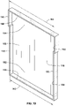
- FIG. 10 illustrates a cross-sectional view of an embodiment of filter cartridge 23 taken along the line 10-10 in FIG. 3 .
- the inlet flow face 48 of the stack of filter media 46 extends generally along a first plane P1.
- the top surface 131 of the top portion 130 of the end frame 127 extends generally along a second plane P2.
- the first plane P1 of the media pack is located a distance D1 below the second plane P2 of the frame, e.g., the inlet flow face 48 of the stack of filter media 46 is located below, e.g., recessed from, the top surface 131 of the top portion 130 of the end frame 127.
- the seal 128 extends around the lower surface of the top portion 130 of the end frame 127 and is spaced radially outward from the perimeter of the media pack.
- the seal 128 may be a non-urethane seal, a synthetic rubber seal, an ethylene propylene diene monomer seal, or a nitrile seal. Other suitable seal materials may be used.
- the seal 128 is coupled to the lower surface of the top portion 130 of the end frame 127 and is configured to prevent passage of fluid bypassing the filter cartridge 23 between the housing 22 and the top portion 130 when the filter cartridge 23 is installed in the housing 22. If the seal is preformed, the seal 128 may be coupled to the top portion 130 by suitable adhesive or can alternatively be mechanically attached in a groove or snap-on arrangement. In other embodiments, the seal 128 may be coupled to the top portion 130 by any other suitable mechanism.
- the filter cartridge 23 includes a first end wall 160 and a second end wall 162 which may be preformed plastic panels like end caps, each wall 160 and 162 being identical to the other.
- the first end wall 160 is configured to be coupled to the first end 52 of the stack of filter media 46.
- the second end wall 162 is configured to be coupled to the second end 54 of the stack of filter media 46.
- the end walls 160 and 162 are coupled to the stack of filter media 46 with a sealant and/or adhesive, such as rigid urethane, hot melt adhesive, epoxy, or plastisol, or the like.
- each end wall 160 and 162 is generally cup shaped to provide an end cap structure.
- End walls 160 and 162 include a central portion 164 and an outer wall portion 166 extending generally perpendicularly to central portion 164 around the perimeter of the central portion 164.
- the central portion 164 includes a first lower portion 168 extending a width W1 and a second upper portion 170 extending a width W2.
- the width W2 is greater than the width W1.
- Upper portion 170 extends above the inlet flow face to receive and cap opposed ends of the end frame 127.
- the central portion 164 of the first end wall 160 is configured to be located proximate the first end 52 of the stack of filter media 46.
- the lower portion 171 of the outer wall portion 166 is configured to be located under the outlet flow face 50 of the stack of media 46.
- the upper portion 172 of the outer wall portion 166 is configured to be located in the first channel 156 of the end frame 127 seated against the upper surface of the first horizontal wall portion 152.
- the first end wall 160 includes first and second vertical wall portions 174 and 176 of the outer wall portion 166 on opposite sides of the second upper portion 170.
- the inner surfaces of the first and second vertical wall portions 174 and 176 are configured to be located proximate the outer surfaces of the first and second legs 144 and 146 respectively when the first end wall 160 is coupled to the stack of filter media 46.
- the first end wall 160 also includes third and fourth vertical wall portion 177 and 179 of the outer wall portion 166 on opposite sides of the first lower portion 168.
- the inner surfaces of the third and fourth vertical wall portions 177 and 179 are configured to be located proximate the second sidewall 58 and first sidewall 56 of the filter media 46 respectively.
- the first end wall 160 may also be coupled to the end frame 127 with adhesive and also seals to the frame to prevent fluid bypass at the interface.
- the outer wall portion 166 of the first end wall 160 is sized and configured to fit around the stack of filter media 46, the legs 144 and 146, and the first horizontal wall portion 152 of the end frame 127, thereby capping and sealing ends of the media pack and frame to prevent fluid bypass when assembled with sealant adhesive.
- the outer wall portion 166 overlaps with the first leg 144 in a direction along the first sidewall 56 of the stack of filter media 46. Additionally, when the upper portion 172 of the outer wall portion 166 is located in the first channel 156 of the end frame 127, the outer wall portion 166 overlaps with the second leg 146 in a direction along the second sidewall 58 of the stack of filter media 46.
- the central portion 164 of the end wall 160 overlaps with both the first leg 144 and the second leg 146 in a direction along the first end 52 of the stack of filter media 46.
- the upper portion 172 of the outer wall portion 166 overlaps with the first horizontal wall portion 152 in a direction along the inlet flow face 48 of the filter media 46.
- End wall 162 is identical to first end wall in structure and function but will be described below.
- End wall 162 includes a central portion 178 and an outer wall portion 180 extending generally perpendicularly to the central portion 178 around the perimeter of the central portion 178.
- the central portion 178 includes a first lower portion 182 extending a width W3 and a second upper portion 184 extending a width W4.
- the width W3 is generally the same as the width W1 (see FIG. 12 ).
- the width W4 is generally the same as the width W2 (see FIG. 12 ).
- the width W4 is greater than the width W3.
- the central portion 178 of the second end wall 162 is configured to be located proximate the second end 54 of the stack of media 46.
- the lower portion 186 of the outer wall portion 180 is configured to be located under the outlet flow face 50 of the stack of media 46.
- the upper portion 188 of the outer wall portion 180 is configured to be located in the second channel 158 of the end frame 127 seated against the upper surface of the second horizontal wall portion 154.
- the second end wall 162 includes first and second vertical wall portions 190 and 192 of the outer wall portion 180 on opposite sides of the second upper portion 184.
- the inner surfaces of the first and second vertical wall portions 190 and 192 are configured to be located proximate the outer surfaces of the first and second legs 144 and 146 respectively when the second end wall 162 is coupled to the stack of filter media 46.
- the second end wall 162 also includes third and fourth vertical wall portion 193 and 195 of the outer wall portion 180 on opposite sides of the first lower portion 182.
- the inner surfaces of the third and fourth vertical wall portions 193 and 195 are configured to be located proximate the first sidewall 56 and second sidewall 58 of the filter media 46 respectively.
- the second end wall 162 is also coupled to the stack of filter media 46 with adhesive, and coupled to the end frame 127 with adhesive and with a seal formed therebetween.
- the second end wall 162 may be coupled to the stack of filter media 46 and/or the end frame 127 by any other suitable mechanism.
- the outer wall portion 180 of the second end wall 162 is sized and configured to fit around the stack of filter media 46, the legs 144 and 146, and the second horizontal wall portion 154 of the end frame 127.
- the outer wall portion 180 overlaps with the first leg 144 in a direction along the first sidewall 56 of the stack of filter media 46. Additionally, when the upper portion 188 of the outer wall portion 180 is located in the second channel 158 of the end frame 127, the outer wall portion 180 overlaps with the second leg 146 in a direction along the second sidewall 58 of the stack of filter media 46.
- the central portion 178 of the end wall 162 overlaps with both the first leg 144 and the second leg 146 in a direction along the second end 54 of the stack of filter media 46.
- the upper portion 188 of the outer wall portion 180 overlaps with the second horizontal wall portion 154 in a direction along the inlet flow face 48 of the filter media 46.
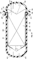
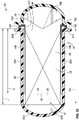
- the housing 26 may have a prior art filter cartridge 194 installed therein.
- Prior art filter cartridge 194 includes two stacks of media that together forming a non-planar V-shaped inlet face.
- the prior art filter cartridge 194 also has a V-shaped outlet face that is non-planar and projects to an apex.
- the prior art filter cartridge 194 may be removed from the housing 22, e.g., when the filter cartridge 194 is spent, etc., and the new filter cartridge 23 according to embodiments of the present invention may be inserted into the housing 22.
- the filter cartridge 23 of embodiments of the present invention is located inside the outlet portion 26 of the housing 22, with the inlet portion 24 of the housing 22 removed.
- the seal 128 is located between the top portion 130 of the end frame 127 and the sealing portions 208 and 210.
- the seal 128 is configured to seal with the sealing portions 208 and 210 to prevent fluid flow from bypassing filtering through the filter media 46 of the filter cartridge 23.
- the outlet flow face 50 of the filter cartridge 23 is located between the first portion 200 of the sidewall 196 and the first portion 202 of the second sidewall 198.
- the outlet flow face 50 of the filter cartridge 23 is generally planar, e.g., does not match the first support feature 33 or the second support feature 35.
- FIG. 17 illustrates a cross-sectional view of the filter cartridge 23 in the housing 22 taken along the line 17-17 in FIG. 1 .
- the inlet portion 24 includes a projecting portion, illustrated in FIG. 17 as an angular locating projection 199.
- the angular locating projection 199 is shaped to match the angled inlet flow face 197 of the filter cartridge 194.
- the flat inlet flow face 48 of the stack of filter media 46 is located below the top surface 131 of the top portion 130 of the end frame 127, the filter cartridge 23 is configured to accommodate the angular locating projection 199, e.g., with the planar inlet flow face 48, not requiring the angled, non-planar inlet flow face 197 of the filter cartridge 194.
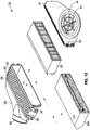
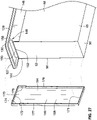
- the filter cartridge 301 includes a prefilter, illustrated in FIG. 18 as a foam pad prefilter 302.
- the prefilter 302 is located upstream of the inlet flow face 348 of the filter media 346.
- the prefilter 302 includes generally open material having filter density of between approximately 75 pores per inch (PPI) and approximately 90 PPI.
- the pore size of the prefilter 302 is approximately 50 micron ( ⁇ m).
- the prefilter 302 is configured to trap larger particle (e.g., particles greater than 50 ⁇ m, etc.) to prevent clogging of the fluted filter media 346. Additionally, the prefilter 302 is configured to minimize pressure drop thereacross. In one embodiment, the pressure drop across the prefilter 302 is between approximately 0.5 in. H20 and approximately 2 in. H20. In one embodiment, the prefilter 302 is formed from reticulated foam-polyester. In another embodiment, the prefilter 302 is formed from nonwoven polyester. In other embodiments, other suitable materials may be used.
- the prefilter 302 is located between the inlet flow face 348 of the filter media 346 and the ribs 342 of the end frame 327.
- the prefilter 302 is recessed below the top surface 331 of the end frame 327, and, therefore, as in the previous embodiment (see FIG. 17 ), the filter cartridge 301 may accommodate the angular locating projection 199 of the filter cartridge, e.g., the angular locating projection may project downwardly past the top surface 331 of the end frame 327 between the ribs 342, without, e.g., damaging, deforming, etc., the prefilter 302 or the filter media 348.
- the prefilter 302 extends from one side of the vertical wall portion 350 of the end frame 327 to the other side of the vertical wall portion 350, therefore, fluid to be filtered passes through the prefilter 302 before passing through the filter media 346, e.g., fluid to be filtered is prevented from bypassing the prefilter 302 to pass through the filter media 346 without passing through the prefilter.
- the prefilter 302 is held in place by the ribs 342 of the end frame 327 and by the inlet flow face 348 of the filter media 346, e.g., is not coupled to the end frame 327 or the filter media 346.
- the prefilter 302 is coupled to the filter media 346 (e.g., by fasteners, adhesive, etc.).
- the prefilter 302 is coupled to the end frame 327 (e.g., by fasteners, adhesive, etc.).
- the prefilter 302 is coupled to both the end frame 327 and the filter media 346.
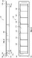
- an alternative filter cartridge 523 is illustrated. Because the filter cartridge 523 is inserted into the housing 22 in a horizontal orientation, the filter cartridge 523 is mounted in a cantilevered state. To reduce or eliminate the torques imparted on the frame 527 of the filter cartridge 523, a support arrangement 511 is added proximate the outlet end 550 of the block of filter media 546 and spaced away from frame 527 proximate the inlet end 548 of the block of filter media 546.
- the support arrangement 511 extends between the block of filter media 546 and the body section of housing 22 to support the cantilevered end, i.e. outlet end 550 of the filter cartridge 523.
- the support arrangement 511 preferably contacts, at least, the inner surfaces of the top and bottom walls 37, 39 of the filter housing 22.
- the support arrangement 511 is provided by a plurality of standoffs 555 attached to first and second sidewalls 556, 558 of the filter cartridge 523.
- the standoffs 555 preferably have canted faces that face the inlet and outlet ends 548, 550 of the filter cartridge 523. The canted faces help facilitate insertion and removal of the filter cartridge 523 from the filter housing 22.
- standoffs 555 there are four standoffs 555, two on the first sidewall 556 and two on the second sidewall 558.
- more or less standoffs 555 are possible.
- a single standoff 555 could be attached to the sidewalls 556, 558.
- the standoffs 555 could have different dimensions.
- a single standoff could be provided that extends the entire width of the filter cartridge 523 as the two illustrated standoffs 555 on a single side.
- the standoffs 555 could be preformed and then attached to the rest of the filter cartridge, e.g. the filter media 546, using an adhesive or could be molded directly thereto.
- the standoffs 55 could be rigid such as from a hard plastic or formed from a softer more compliant material such as a foamed urethane.
- the standoffs 555 could be attached to end walls 560, 562. By being attached, they could be separately formed from end walls 560, 562 or molded with the end walls 560, 562 as a single component.
- the standoffs 555 could take other shapes such as domed structures. Further, the standoffs 555 could extend outward in a horizontal direction from the sidewalls 560, 562 to contact the sides of the housing 22 to further improve the location of the free end of the filter cartridge 523.
- the inclusion of the support arrangement 511 helps further combat vibrational forces that may act on the filter cartridge 523.
- FIG. 32 illustrates a further embodiment of a support arrangement illustrated in as a continuous band 655 that circumscribes the rest of the filter cartridge 623, i.e. the block of filter media 646 and end walls 660, 662.
- the band 655 would contact all of the sides of the housing 22.
- the band is formed from a permeable material so as to prevent forming a seal between the filter housing 22 and filter cartridge 623.
- the band may include air flow apertures formed axially therethrough specifically to prevent any such sealing function.
- the band may be formed from a more rigid material such as a hard plastic or a softer more compliant material such as a foamed urethane.
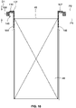
- the width W of the filter cartridge 23 is less than a width between the opposed angular support features 31 of the filter housing 22 and the length L of the filter cartridge 23 from seal 128 to the opposite free end of the filter cartridge is greater than the depth D of the filter housing from the inlet opening to the angular support features 31.
- This arrangement allows for the filter cartridge 23 to bypass the angular support features 31 such that the filter cartridge can extend deeper into the filter housing 22 when installed. This allows for additional length of the filter cartridge 23 and to increase the amount of filter media that can be provided.
- the length L of the filter cartridge 23 from seal 128 to the opposite free end is greater than the depth D2 of the filter housing 22 such that the outlet end 50 of the filter cartridge 23 is inserted axially past the apex or junction of support sidewalls 33, 35 of the angular support features 31.
- a method of replacing a filter cartridge, such as cartridge 194, that cooperates with the angular support feature 31 with a filter cartridge that does not cooperate with the angular support feature 31 is provided.
- the method would include inserting a filter cartridge, such as version of filter cartridge 23, where the length L is greater than distance D and more preferably greater than distance D2 such that the outlet end of the filter cartridge is inserted past, at least a portion, of the angular support feature 31.
- support features 31 will typically include the support arrangements for supporting the cantilevered free end of the filter cartridge 23, such as standoffs 555 and band 655 discussed above.
Description
- The present invention generally relates to fluid filtration, and more particularly to filter assemblies including filter housings and filter cartridges.
- Various systems require filtration of fluid prior to use of the fluid within the system. For instance, engines utilize air filtration systems for filtering air, the fluid, prior to using the air within the engine to combust a fuel. These filtration systems will typically utilize a housing that cooperates with a replaceable filter cartridge to filter the flowing fluid. When the filter cartridge becomes spent, such as when it has become full with removed dust particulates from the flowing fluid, the filter cartridge can be removed from the filter housing.
- One particular type of filter cartridge used in air filtration is fluted filter media, which as used herein will be broad enough to include, but not limited to gathered, corrugated and tapered, fluted filter media. In one instance, the filter media stacked to form a block of filter media.
-
US 7,625,419 B2 discloses an air filter arrangement with a filter cartridge which include a recessed first flow face and an opposite outwardly projecting second flow face which has a central apex, and a V-shaped flow face of the filter media is configured for receiving a protrusion.WO 2010/114906 A1 relates to a filter cartridge which includes a media pack which has first and second opposite flow faces and it is suggested to mount a seal member onto a seal support section.EP 1 712 266 A1 relates to an air filter element which has a sealing ring which is welded, glued, extruded or fused on to its base. - One embodiment of the invention relates to a filter assembly comprising at least the features of claim 5. The filter assembly includes a filter housing. The filter housing defines an internal cavity, an inlet, and an outlet. The filter assembly includes a filter cartridge. The filter cartridge includes a stack of filter media. The stack of filter media includes an inlet flow face and an outlet flow face. The filter cartridge includes a frame coupled to the filter media. At least a portion of the filter cartridge is located within the internal cavity of the filter housing. The frame member defines an opening through which fluid may be directed to the inlet flow face of the filter media. The frame member includes a top surface. The inlet flow face is recessed below the top surface of the frame member. This may receive a projection from a housing.
- An advantage of this design is that a simple rectangular stack (including substacks if desired) can be used with the media pack having a flat inlet face. Complex fluted media packs therefore need not be formed and fixture and tooling manufacture for the same are avoided.
- A projecting portion of the housing projects into the opening defined by the frame member. The frame member surrounds the projecting portion of the housing and provides clearance due to the inlet flow face being recessed below the top surface of the frame member.
- In a more particular embodiment, the frame includes a first leg and a second leg. The first and second legs are located on opposite sides of the opening. The filter cartridge is located between the first leg and the second leg.
- In one particular embodiment, the frame includes a rectangular top portion extending around the opening and defines a larger perimeter than the stack. The filter assembly also including a sealing member coupled to the top portion outside the legs and which extends around the opening. The sealing member is configured to seal with the filter housing to prevent fluid flow from bypassing the filter cartridge when the filter cartridge is installed in the filter housing. The sealing member is spaced above the inlet flow face.
- In one particular embodiment, the filter cartridge includes a first end cap sealing one side of the filter media and overlapping with the frame member. The filter cartridge includes a second end cap sealing another side opposite the one side of the filter media. The second end cap overlapping with the frame member.
- In one particular embodiment, the frame includes a plurality of ribs extending across the opening and below the top surface of the frame. The ribs run across and over the inlet flow face of the filter cartridge. The ribs may be recessed from the top surface of the frame member.
- In one particular embodiment, the filter housing includes a first wall and a second wall. The first wall includes a first portion and a second portion. The second wall includes a first portion and a second portion. The first portion of the first wall and the first portion of the second wall are generally parallel. The second portion of the first wall and the second portion of the second wall converge towards one another proximate the outlet. The outlet flow face is flat. The filter cartridge has a guide mechanism projecting from the outlet flow face to engage the first and second portions.
- In a more particular embodiment, the outlet flow face of the filter media is located between the first portion of the first wall and the first portion of the second wall when the filter cartridge is installed in the filter housing. The guide mechanism includes converging blades projecting from opposing sides of the stack and into a region between the second portions.
- In one embodiment, the stack of filter media includes a first side and a second side opposite the first side. The first and second sides extend generally perpendicular to the inlet and outlet flow faces and generally parallel to one another. The frame member defines a first channel proximate the first side and a second channel proximate the second side. The filter cartridge further includes a first end wall extending generally over the first side of the filter media. The first end wall includes a central portion and an outer wall portion extending generally perpendicularly to the central portion. The outer wall portion includes an upper portion configured to be located in the first channel of the frame member. The filter cartridge includes a second end wall extending generally over the second side of the filter media. The second end wall includes a central portion and an outer wall portion extending generally perpendicularly to the central portion. The outer wall portion of the second end wall includes an upper portion configured to be located in the second channel of the frame member.
- Another embodiment of the invention relates to a method of replacing a filter cartridge in a filter assembly, the method comprising at least the features of claim 1. The filter assembly includes a filter housing. The filter housing defines an internal cavity, an inlet, and an outlet. The filter housing includes sidewalls proximate the outlet extending inwardly toward one another. The method includes providing a filter cartridge. The filter cartridge includes a fluted filter media and a frame member. The fluted filter media has an inlet flow face and an outlet flow face. The flutes of the fluted filter media extend from the inlet flow face to the outlet flow face. The outlet flow face is generally planar. The frame member includes a top portion having a top surface. The top portion extends from a first end to a second end. The top portion defines a central opening. The frame member is coupled to the fluted filter media such that fluid may be directed through the central opening to the inlet flow face of the filter media. The inlet flow face of the filter media is recessed below the top surface of the top portion. The method includes locating the filter cartridge in the internal cavity of the filter housing.
- In a more particular embodiment, the sidewalls of the filter housing include a first section where the sidewalls extend generally parallel to one another. The outlet flow face of the filter media is located between the first section of the sidewalls when the filter cartridge is located in the internal cavity of the filter housing.
- In another embodiment, the method includes removing a filter cartridge including removing a media pack arrangement with filter media having first and second opposite flow faces. The media pack arrangement has a first recessed central region in one of the flow faces prior to locating the filter cartridge in the internal cavity of the filter housing.
- In one embodiment, the filter cartridge further includes a seal member coupled to the frame member. The step of locating the filter cartridge in the internal cavity of the filter housing includes locating the seal against the filter housing to prevent contaminated fluid from passing into the filter housing.
- Another embodiment of the invention relates to a filter cartridge. The filter cartridge includes filter media. The filter media includes a generally rectangular inlet flow face, an outlet flow face, and opposite first and second and opposite third and fourth sides extending from the inlet flow face to the outlet flow face. The first, second, third, and fourth sides each extend generally perpendicularly to the inlet flow face and the outlet flow face. The first side extends along a first plane. The second side extends along a second plane. The third side extends along a third plane. The fourth side extends along a fourth plane. The filter cartridge includes a frame member coupled to the filter media. The frame member defines a generally rectangular opening through which fluid may pass to the inlet flow face. The frame member includes a top portion and first and second legs spaced apart from one another. The first leg is coupled to the first side of the filter media. The second leg is coupled to the second side of the filter media. The filter cartridge includes a first end cap sealing the third side of the filter media. The first end cap overlaps with the first leg and the second leg in at least one direction parallel to either the first, third, or fourth planes. The filter cartridge includes a second end cap. The second end cap seals the fourth side of the filter media. The second end cap overlaps with the first leg and the second leg in at least one direction parallel to either the second, third, or fourth planes.
- In a more particular embodiment, the first end cap overlaps with the first leg and the second leg in a direction parallel to the first, third, and fourth planes.
- In one embodiment, the second end cap overlaps with the first leg and the second leg in a direction parallel to the second, third, and fourth planes.
- The filter cartridge includes a seal extends under and around the top portion of the frame. The seal is configured to be located against a filter housing to prevent contaminated fluid from passing into the filter housing.
- Another embodiment of the invention relates to a filter cartridge. The filter cartridge includes a stack of sheets of fluted filter media configured in a generally rectangular block having an inlet flow face and an outlet flow face. The filter cartridge also includes a frame coupled to the block of fluted filter media. The frame includes a top portion extending around and upwardly from the inlet flow face. The frame includes a pair of legs extending down toward the outlet flow face of the filter media. The frame defines a generally rectangular opening through which fluid may pass to the inlet flow face of the filter media. The top portion of the frame extends outwardly away from the filter media. The filter cartridge includes a seal member. The seal member extends around the filter media. The seal member is coupled to the portion of the top portion of the frame extending outwardly away from the filter media.
- The outlet flow face and the inlet flow face are each generally planar.
- In one embodiment, the frame includes a connection portion extending between the top portion and the legs. The connection portion defines a pair of channels. The filter cartridge includes first and second end walls. Each end wall is configured to couple and/or is operably coupled to the filter media and to interface with one of the channels defined by the connection portion of the frame.
- In one embodiment, the seal member is a foam pad prefilter.
- In one embodiment, the frame member has a top surface. The inlet flow face of the filter media is recessed below the top surface of the frame member.
- A filter cartridge is disclosed herein. The filter cartridge includes a stack of sheets of fluted filter media configured in a generally rectangular block having an inlet flow face and an outlet flow face. A prefilter may be located upstream of the inlet flow face. A frame is coupled to the block of fluted filter media. The frame includes a top portion extending around and upwardly from the inlet flow face and the prefilter. A pair of legs extends past the prefilter and down toward the outlet flow face of the filter media. The frame defines a generally rectangular opening through which fluid may pass to the prefilter. The top portion of the frame extends outwardly away from the filter media. The prefilter the inlet flow face are recessed below a top surface of the frame.
- In a more particular embodiment, the frame includes ribs extending across the generally rectangular opening. The prefilter is located between the ribs and the inlet flow face.
- Other aspects, objectives and advantages of the invention will become more apparent from the following detailed description when taken in conjunction with the accompanying drawings.
- The accompanying drawings incorporated in and forming a part of the specification illustrate several aspects of the present invention and, together with the description, serve to explain the principles of the invention. In the drawings:
-
FIG. 1 is a perspective view of an embodiment of a filter assembly; -
FIG. 2 is a perspective view of an embodiment of a filter assembly with a housing in a partially opened configuration; -
FIG. 3 is a perspective view of an embodiment of a filter assembly in an exploded configuration; -
FIG. 4 is an exploded view of an embodiment of a filter cartridge; -
FIG. 5 is an exploded view of an embodiment of a stack of filter media, a portion of protective material, and an embodiment of a guide mechanism; -
FIG. 6 is an exploded view of an embodiment of a filter cartridge; -
FIG. 7 is an top perspective view of an embodiment of an end frame; -
FIG. 8 is an end view of an embodiment of an end frame; -
FIG. 9 is a side view of an embodiment of an end frame; -
FIG. 10 is a cross-sectional view taken along the line 10-10 inFIG. 3 ; -
FIG. 11 is a bottom view of an embodiment of an end frame; -
FIG. 12 is a perspective view of an embodiment of an end wall; -
FIG. 13 is a perspective view of an embodiment of an end wall; -
FIG. 14 is a cross-sectional view taken along the line 14-14 inFIG. 3 ; -
FIG. 15 is a perspective view of two embodiments of filter cartridges illustrating removal of a first filter cartridge from an embodiment of a housing and inserting the embodiment of a second filter cartridge into the embodiment of the housing; -
FIG. 16 is a perspective view of the embodiment of the second filter cartridge illustrated inFIG. 15 in an embodiment of a housing; -
FIG. 17 is a cross-sectional view taken along the line 17-17 inFIG. 1 ; -
FIG. 18 is a perspective view of another embodiment of a filter cartridge; and -
FIG. 19 is a cross-sectional view taken along the line 19-19 inFIG. 18 ; -
FIG. 20 is a detail view of thearea 20 inFIG. 5 ; -
FIG. 21 is a detail view of thearea 21 inFIG. 5 ; -
FIG. 22 is a perspective view of an embodiment of a portion of a guide mechanism; -
FIG. 23 is a perspective view of an embodiment of a portion of a guide mechanism; -
FIG. 24 is a perspective view of another embodiment of a guide mechanism; -
FIG. 25 is a view of another embodiment of a stack of filter media, a portion of protective material, and an embodiment of a guide mechanism; -
FIG. 26 is a perspective view of an embodiment of a sheet of double-faced fluted filter media; -
FIG. 27 is a view illustrating coupling of an embodiment of an end wall to an embodiment of an end frame and an embodiment of a stack of filter media; -
FIG. 28 is a view illustrating coupling of an embodiment of an end wall to an embodiment of an end frame and an embodiment of a stack of filter media; -
FIG. 29 is a cross-sectional view taken along the line 29-29 inFIG. 3 ; -
FIG. 30 is a cross-sectional view taken along the line 30-30 inFIG. 16 ; -
FIG. 31 is a perspective view of an alternative embodiment of a filter assembly in an exploded configuration; -
FIG. 32 is a perspective view of an alternative embodiment of a filter assembly in an exploded configuration; and -
FIG. 33 is an alternative cross-sectional illustration similar toFIG. 17 showing an alternative filter cartridge having an increased length and reduced width. - While the invention will be described in connection with certain preferred embodiments, there is no intent to limit it to those embodiments. The scope of the invention is defined by the appended claims.
-
FIG. 1 illustrates afilter assembly 20 according to a first embodiment of the present invention. Thefilter assembly 20 is generally configured for removing contaminants and particulates from within a flowing fluid stream, such as an air stream. Typically, the air stream may be used for supplying air to an engine such as an internal combustion engine or turbine. However, embodiments of filter assemblies can be used for alternative systems, as well as for filtering other fluids, such as liquids. Generally, embodiments of filter assemblies include a housing and a filter cartridge. When the filter cartridge is spent, it is removed from the housing and replaced. - With further reference to
FIG. 1 , in one embodiment, thefilter assembly 20 includes ahousing 22 and a filter cartridge 23 (not illustrated inFIG. 1 , seeFIG. 2 ) internally received into thehousing 22. Thehousing 22 includes aninlet portion 24 and anoutlet portion 26. Theinlet portion 24 and theoutlet portion 26 are separable from one another (see, e.g.,FIG. 2 ). Theoutlet portion 26 includes abody section 28 into which thefilter cartridge 23 is located during installation. - With further reference to
FIG. 1 , theinlet portion 24 includes aninlet adapter 30 with aninlet aperture 32 therethrough. During operation, air to be filtered passes through theinlet aperture 32 to the interior of thehousing 22. Theadaptor 30 is configured to receive a bellows or other mechanism inside of an engine compartment of a vehicle, e.g., a truck, etc. Theadapter 30 may be a preformed, plastic part. - During operation, unfiltered air passes through the
inlet aperture 32, through theinlet portion 24 and toward theoutlet portion 26 with the air passing through thefilter cartridge 23 to filter the air. The filtered air exits thefilter assembly 20 through anoutlet 34. - With further reference to
FIG. 1 , theoutlet portion 26 includes arib pattern portion 36. Therib pattern portion 36 may provide strengthening of the surface of theoutlet portion 26. The opposite side of the outlet portion 26 (not illustrated inFIG. 1 ) also includes a rib pattern portion. - As is illustrated in
FIG. 1 , theoutlet portion 26 provides mountingposts 38 and mountingbrackets 40 configured to mount thehousing 22, e.g., in a vehicle. Theoutlet portion 26, upon mounting, is fixed in place and is not movable with respect to the mounting, e.g., with respect to the vehicle, without dismounting thehousing 22, while theinlet portion 24 is removable to provide access to the interior of thehousing 22. -
Bolts 42 are configured to secure theinlet portion 24 to theoutlet portion 26, e.g., to nut plates of theoutlet portion 26. In other embodiments, other suitable fasteners and/or coupling mechanisms may be used. When theinlet portion 24 is to be removed from theoutlet portion 26, thebolts 42 may be loosened or removed to allow theinlet portion 24 to be moved away from theoutlet portion 26, as is illustrated inFIG. 2 . - With further reference to
FIG. 2 , thehousing 22 includes a releasable hinge configured to allow pivotal displacement of theinlet portion 24 relative to the outlet portion 26 (as illustrated inFIG. 2 ) and detachment of theinlet portion 24 from the outlet portion 26 (as illustrated inFIG. 3 ). - With reference to
FIG. 3 , with theinlet portion 24 removed from theoutlet portion 26, thefilter cartridge 23 may be removed from or located within thefilter housing 22. InFIG. 3 , a portion of thebody section 28 is shown cut away to illustrate interior features of thehousing 22. Extending inwardly from each of thesidewalls 29 of thebody section 28 is an angular support feature 31 (only onesupport feature 31 visible inFIG. 3 ). Thesupport feature 31 includes first andsecond support walls support walls inlet portion 24 and toward one another generally towards an apex or junction region. -
FIG. 4 illustrates an exploded view of an embodiment of afilter cartridge 23. Thefilter cartridge 23 includes a stack offilter media 46. As illustrated inFIG. 4 , the stack offilter media 46 is configured in a generally rectangular block. Thefilter media 46 includes a flatinlet flow face 48 and a flatoutlet flow face 50. As such, no offsetting or complex configuration of the media is needed. Instead, a simple rectangular stack can be used. The inlet and outlet flow faces 48 and 50 are generally parallel to one another and generally perpendicular to the direction of fluid flow. Each of theinlet flow face 48 and the outlet flow face 50 is generally planar. Thefilter media 46 extends from afirst end 52 to asecond end 54 in a direction generally perpendicular to the direction of fluid flow and perpendicular to theinlet 48 andoutlet 50 flow faces and from afirst sidewall 56 to asecond sidewall 58. The inlet and outlet flow faces 48 and 50 are generally flat and extend generally perpendicular to thesidewalls - The
filter media 46 is preferably fluted media. In one embodiment, the fluted media is corrugated media. In another embodiment, the flutes of the fluted media are formed by folding. In other embodiments, the fluted media may be formed by any suitable method or mechanism. In other embodiments, the filter media may be any other suitable type of media. Thefilter media 46 may include a plurality of inlet flutes and plurality of outlet flutes. The inlet flutes are open proximate theinlet flow face 48 and sealed proximate theoutlet flow face 50, e.g., sealed with a bead of adhesive, etc. The outlet flutes are sealed proximate theinlet flow face 48, e.g., sealed with a bead of adhesive, etc., and open proximate theoutlet flow face 50. For example, a stack of fluted media can be accomplished in accordance withU.S. Patent No. 5,820,646 . - With reference to
FIG. 5 , an exploded view of an embodiment of a stack offilter media 46 is illustrated. The stack offilter media 46 includes a first stack offilter media 60 and a second stack offilter media 62. The first andsecond stacks rectangular sheets FIGS. 20 and 21 ). The generally rectangular peripheries of thesheets opposite sides stacks upper surface 78 of thefirst stack 60 and thelower surface 80 of thesecond stack 62. - With reference to
FIG. 20 , in one embodiment, each of thesheets 66 of thefirst stack 60 includes abacking sheet 82 and afluted sheet 84. The flutes project in a generally wave-like pattern. At one end a sealing bead between thefluted sheet 84 and thebacking sheet 82 seals one end of alternating and/or adjacent ones of the flutes. At the other end, a sealing bead between thebacking sheet 82 and a fluted sheet of anothersheet 66 seals one end of alternating and/or adjacent flutes. Thefirst stack 60 includes adjacent flutes having alternating first closed ends and second closed ends to provide for substantially straight through flow of the fluid between the upstream flow and the downstream flow. With this arrangement, the fluid to be filtered must pass through the filter media trapping dust carried thereby, and then pass into an adjacent flute open at the outlet end for exit. - The
sheets 66 are stacked in the same orientation with the first, generallyflat sides 82 of thesheets 66 facing upwardly. In one embodiment, thesheets 66 are coupled together to form thefirst stack 60. Thesheets 66 are coupled together with adhesive. - Forming the
filter media 46 with afirst stack 60 and asecond stack 62 coupled together with adhesive may add strength to thefilter media 46 and may prevent telescoping of the stack offilter media 46, e.g., movement of thesheets - With reference to
FIG. 21 , in one embodiment, each of thesheets 68 of thesecond stack 62 includes abacking sheet 86 and afluted sheet 88. The flutes project in a generally wave-like pattern. At one end a sealing bead between thefluted sheet 88 and thebacking sheet 86 seals one end of alternating ones of the flutes. At the other end, a sealing bead between the backing sheet 86 a fluted sheet of anothersheet 68 seals one end of alternating flutes. Thesecond stack 62 includes adjacent flutes having alternating first closed ends and second closed ends to provide for substantially straight through flow of the fluid between the upstream end and the downstream end, with flow having to pass through either one of the backing sheets or fluted sheets. - The
sheets 68 are stacked in the same orientation with thebacking sheet 86 of thesheets 68 facing downwardly. Thesheets 68 may be coupled together to form thesecond stack 62. Thesheets 68 may be coupled together with adhesive. - With further reference to
FIGS. 5, 20 and 21 , in one embodiment, thefirst stack 60 and thesecond stack 62 are coupled together to form the stack offilter media 46. Thefirst stack 60 has aninlet flow face 90. The inlet flow face 90 is generally perpendicular to theopposite sides first stack 60. The inlet flow face 90 is also generally perpendicular to theupper surface 78 of thefirst stack 60. Thesecond stack 62 also has aninlet flow face 92. The inlet flow face 92 is generally perpendicular to theopposite sides second stack 62. The inlet flow face 92 is also generally perpendicular to thelower surface 80 of thesecond stack 62. The inlet flow faces 90 and 92 together form the combined flat or overall inlet flow face 48 of the stack of filter media 46 (seeFIG. 4 ), when thestacks filter media 46. - With reference to
FIGS. 4 and5 , in one embodiment, theside 70 of thefirst stack 60 and theside 74 of thesecond stack 62 together form thefirst end 52 of the stack offilter media 46. Theside 72 of thefirst stack 60 and theside 76 of thesecond stack 62 together form thesecond end 54 of the stack offilter media 46. Thesides inlet 48 andoutlet 50 flow faces. - With reference to
FIGS. 4 and25 , in another embodiment, the stack offilter media 46 includes a single stack offilter media 65. The single stack offilter media 65 includes a plurality of generallyrectangular sheets 67 of fluted media (seeFIG. 26 ). The generally rectangular peripheries of thesheets 67 are aligned to form the rectangular stack offilter media 46. -
FIG. 26 illustrates one embodiment of asheet 67 of filter media. A portion of a layer of double-faced permeablefluted filter media 67 is illustrated. Thesheet 67 includesflutes 69 that form a corrugated-type material. Theflutes 69 are formed by acenter fluting sheet 75 formed intopeaks 71 andtroughs 73 between a facingsheets 77. Thepeaks 71 andtroughs 73 divide the flutes into an upper row and a lower row. In the configuration shown inFIG. 26 , the upper flutes formflute chambers 81 closed at the downstream end, while upstream closed end flutes 79 are the lower row of flute chambers. Thefluted chambers 79 are closed by afirst end bead 83 filling a portion of the upstream end of the flute between thefluting sheet 75 and the lower facingsheet 77. Similarly, asecond end bead 85 closes the downstream end of alternatingflutes 81. Adhesive tacks 87 connect thepeaks 71 andtroughs 73 of theflutes 69 to the facingsheets 77. In one embodiment, the adhesive of thetacks 87 is placed only at the apexes of thepeaks 71 andtroughs 73, rather than as a continuous bead, as shown inFIG. 26 . The minimal amount of adhesive keeps the chambers of the flutes open to accept increased fluid flow. Theflutes 69 and endbeads - When filtering, unfiltered fluid enters the
flute chambers 81 which have their upstream ends open as indicated by the shaded arrows. Upon entering theflute chambers 81, the unfiltered fluid flow is closed off by thesecond end bead 85. Therefore, the fluid is forced to proceed through one of thefluting sheets 75 orface sheets 77. - With further reference to
FIG. 5 , in one embodiment, upon forming the stack offilter media 46, in one embodiment, aprotective wrap 64, is coupled to and generally covers oneside 78 of thefirst stack 60. Thewrap 64 may be a sheet of paper material or plastic material. Additionally, in one embodiment, another wrap 64', is coupled to and generally covers anopposite side 80 of thesecond stack 62. - With reference to
FIG. 4 , in another embodiment, thefirst end 52, thesecond end 54, thefirst sidewall 56, and thesecond sidewall 58 of the stack offilter media 46 are covered with a protective outer wrapper, e.g., the stack offilter media 46 is wrapped with an outer wrapper extending around thefirst end 52, thefirst sidewall 56, thesecond end 54, and thesecond sidewall 58 of the stack offilter media 46. In one embodiment, the outer wrapper does not extend over the inlet flow face 48 or the outlet flow face 50 of thefilter media 46. - With further referent to
FIG. 4 , in one embodiment, the stack ofmedia 46 is deep pleated media. In any of the embodiments described herein whether pleated or fluted, the stack ofmedia 46 may extend a depth between theinlet flow face 48 and the outlet flow face 50 of at least approximately 6 inches; and the stack ofmedia 46 may extend a length between thefirst end 52 and thesecond end 54 of between approximately 12 inches to approximately 36 inches; and the stack of media may extend a width between thefirst sidewall 56 and thesecond sidewall 58 of between approximately three inches and approximately nine inches. - With reference to
FIGS. 5 ,22 and 23 , a guide mechanism, illustrated inFIG. 5 as first andsecond guides first guide 94 includes afirst wall portion 98 and a secondangular wall portion 100 extending from thefirst wall portion 98. Thefirst wall portion 98 extends generally along a first plane, while the secondangular wall portion 100 extends generally along a second plane non-parallel and non-coplanar with the first plane. Thefirst wall portion 98 and the secondangular wall portion 100 preferably extend generally the same length. In another embodiment, thefirst wall portion 98 extends a length shorter than the secondangular wall portion 100. - The
first wall portion 98 is coupled to the wrap 64' proximate theoutlet flow face 50, coupling thefirst guide 94 to the stack ofmedia 46. Thefirst wall portion 94 extends generally parallel to thelower surface 80 of thesecond stack 62. The secondangular wall portion 100 extends non-parallel to thelower surface 80 of thesecond stack 62 forming an angle θ1 with the plane along which thefirst wall portion 98 extends, with the angle θ1 is less than 90°. In one embodiment, thefirst guide 94 extends along thelower surface 80 of thesecond stack 62 from a location proximate theside 74 of thesecond stack 62 to a location proximate theside 76 of thesecond stack 62. - With reference to
FIGS. 5 and23 , in one embodiment, thesecond guide 96 includes afirst wall portion 102 and a secondangular wall portion 104 extending from thefirst wall portion 102. Thefirst wall portion 102 extends generally along a first plane, while the secondangular wall portion 104 extends generally along a second plane non-parallel and non-coplanar with the first plane. Thefirst wall portion 102 and the secondangular wall portion 140 preferably extend generally the same length. In another embodiment, thefirst wall portion 102 extends a length shorter than the secondangular wall portion 104. - As shown, the
first wall portion 102 can be coupled to thewrap 64, proximate the outlet flow face 50 of themedia 46 coupling thesecond guide 96 to the stack ofmedia 46. Thefirst wall portion 102 extends generally parallel to theupper surface 78 of thefirst stack 60. The secondangular wall portion 104 extends non-parallel to theupper surface 78 of thefirst stack 60 forming an angle θ2 with the plane along which thefirst wall portion 102 extends, with the angle θ2 being less than 90°. Thesecond guide 96 extends along theupper surface 78 of thefirst stack 60 from a location proximate theside 70 of thefirst stack 60 to a location proximate theside 72 of thefirst stack 60. Thefirst guide 94 and thesecond guide 96 are generally the same length and are aligned on opposite sides of the stack ofmedia 46. Theguides filter cartridge 23 when thefilter cartridge 23 is being located in thehousing 22, as will be further discussed below. - With reference to
FIG. 24 , an alternate embodiment of a guide mechanism, illustrated as aguide 106, is provided. Theguide 106 includes afirst guide portion 108, asecond guide portion 110 spaced apart from thefirst guide portion 108. Thefirst guide portion 108 includes afirst wall portion 112 and a secondangular wall portion 114 extending downwardly from thefirst wall portion 112. Thefirst wall portion 112 extends along a first plane, while the secondangular wall portion 114 extends along a second plane non-parallel to and non-co-planar with the first plane. Thesecond guide portion 110 includes afirst wall portion 116 generally parallel with thefirst wall portion 112 and a secondangular wall portion 118 extending downwardly from thefirst wall portion 116. Thefirst wall portion 116 extends along a first plane, while the secondangular wall portion 118 extends along a second plane non-parallel to and non-co-planar with the first plane. - With further reference to
FIG. 24 , theguide 106 includes a connecting portion, illustrated inFIG. 24 as a plurality of bridges in the form ofposts first guide portion 108 and thesecond guide portion 110. Thepost 120 extends proximate a first end of thefirst guide portion 108 from thefirst guide portion 108, proximate the location where thefirst wall portion 112 and the secondangular wall portion 114 meet, to thesecond guide portion 110, proximate the location where thefirst wall portion 116 and thesecond wall portion 118 meet. Thepost 122 extends generally parallel to thepost 120 between thepost 120 and thepost 124, from thefirst guide portion 108, proximate the location where thefirst wall portion 112 and the secondangular wall portion 114 meet, to thesecond guide portion 110, proximate the location where the first wall portionfirst wall portion 116 and thesecond wall portion 118 meet. Thepost 124 extends proximate a second end of thefirst guide portion 108 opposite the first end of the first guide portion from thefirst guide portion 108, proximate the location where thefirst wall portion 112 and the secondangular wall portion 114 meet, to thesecond guide portion 110, proximate the location where thefirst wall portion 116 and thesecond wall portion 118 meet. - The
first wall portion 112 of thefirst guide portion 108, thefirst wall portion 116 of thesecond guide portion 110 and theposts channel 126 configured to receive the outlet flow face 50 of thefilter media 46. Thefirst wall portion 112 is configured to be coupled to thefirst sidewall 56 of thefilter media 46 and thefirst wall portion 116 is coupled to thesecond sidewall 58 of thefilter media 46. The secondangular wall portions housing 22, as will be further discussed below. - With further reference to
FIG. 4 , thefilter cartridge 23 includes a frame, illustrated inFIG. 4 as anend frame 127. Thefilter cartridge 23 also includes aseal 128. As illustrated inFIG. 6 , theend frame 127 includes atop portion 130 that is configured to be placed over the inlet face of the fluted media stack. Theframe 127 may include first and second generallyparallel sides fourth sides sides FIGS. 4 and7 , thetop portion 130 extends around a generally rectangularopen center 140 through which fluid flows to the inlet flow face 48 (seeFIG. 4 ) of thefilter media 46. Extending from oneside 132 to theother side 134 across the generally rectangularopen center 140 are a plurality ofribs 142. When theend frame 127 is assembled with the stack offilter media 46, theribs 142 extend from the top surface of theend frame 127 downwardly to the inlet flow face 48 of thefilter media 46. Theribs 142 provide support and also protect the inlet flow face. - With reference to
FIGS. 6 and8 , theend frame 127 also includes afirst leg 144 and asecond leg 146 extending along longitudinal sides of the media pack. Thesecond leg 146 is spaced apart from thefirst leg 144 on the opposite side of theopen center 140. Thefirst leg 144 extends along the same side of theopen center 140 as theside 132 of thetop portion 130. Thesecond leg 146 extends along the other side of theopen center 140, e.g., same side asside 134 of thetop portion 130. - With reference to
FIGS. 6 ,8 , and9 , theend frame 127 also includes aconnection portion 148 on each opposed end (e.g., narrow ends).Portion 148 extends between thetop portion 130 and thelegs connection portion 148 includes a generallyvertical wall portion 150 extending downwardly from the interior periphery of thetop portion 130 and extends around the generally rectangularopen center 140. Theconnection portion 148 also includes firsthorizontal wall portion 152 extending generally perpendicularly from thevertical wall portion 150 distal from thetop portion 130 proximate thethird side 136 of thetop portion 130. Theconnection portion 148 also includes a secondhorizontal wall portion 154 extending generally perpendicularly from thevertical wall portion 150 distal from thetop portion 130 proximate thefourth side 138 of thetop portion 130. The inlet flow face 48 of thefilter media 46 is configured to be received between thefirst leg 144 and thesecond leg 146 and coupled to theend frame 127, with opposite ends of the inlet flow face 48 of thefilter media 46 contacting the first and secondhorizontal wall portions - Thus
legs connection portions 148 generally surround the media pack stack, while thetop portion 130 is over the inlet face with a border extension beyond the periphery of the media pack stack. - In one embodiment, the
end frame 127 is coupled to the stack offilter media 46 by adhesive. For example, the end frame may be coupled with urethane, e.g., SIKAFLEX® urethane, available from Sika Corporation U.S., etc. - As illustrated in
FIG. 9 , thetop portion 130, the generallyvertical wall portion 150 and the firsthorizontal wall portion 152 define afirst channel 156 configured to receive a portion of a first end cap, as will be further described below. Similarly, thetop portion 130, the generallyvertical wall portion 150 and the secondhorizontal wall portion 154 define asecond channel 158 on the opposite side of theend frame 127 configured to receive a portion of a second end cap, as will be further described below. -
FIG. 10 illustrates a cross-sectional view of an embodiment offilter cartridge 23 taken along the line 10-10 inFIG. 3 . The inlet flow face 48 of the stack offilter media 46 extends generally along a first plane P1. Thetop surface 131 of thetop portion 130 of theend frame 127 extends generally along a second plane P2. The first plane P1 of the media pack is located a distance D1 below the second plane P2 of the frame, e.g., the inlet flow face 48 of the stack offilter media 46 is located below, e.g., recessed from, thetop surface 131 of thetop portion 130 of theend frame 127. - With reference to
FIG. 11 , theseal 128 extends around the lower surface of thetop portion 130 of theend frame 127 and is spaced radially outward from the perimeter of the media pack. Theseal 128 may be a non-urethane seal, a synthetic rubber seal, an ethylene propylene diene monomer seal, or a nitrile seal. Other suitable seal materials may be used. Theseal 128 is coupled to the lower surface of thetop portion 130 of theend frame 127 and is configured to prevent passage of fluid bypassing thefilter cartridge 23 between thehousing 22 and thetop portion 130 when thefilter cartridge 23 is installed in thehousing 22. If the seal is preformed, theseal 128 may be coupled to thetop portion 130 by suitable adhesive or can alternatively be mechanically attached in a groove or snap-on arrangement. In other embodiments, theseal 128 may be coupled to thetop portion 130 by any other suitable mechanism. - With reference to
FIG. 4 , thefilter cartridge 23 includes afirst end wall 160 and asecond end wall 162 which may be preformed plastic panels like end caps, eachwall first end wall 160 is configured to be coupled to thefirst end 52 of the stack offilter media 46. Thesecond end wall 162 is configured to be coupled to thesecond end 54 of the stack offilter media 46. In one embodiment, theend walls filter media 46 with a sealant and/or adhesive, such as rigid urethane, hot melt adhesive, epoxy, or plastisol, or the like. - With reference to
FIG. 12 , eachend wall End walls central portion 164 and anouter wall portion 166 extending generally perpendicularly tocentral portion 164 around the perimeter of thecentral portion 164. Thecentral portion 164 includes a firstlower portion 168 extending a width W1 and a secondupper portion 170 extending a width W2. In one embodiment, the width W2 is greater than the width W1. The increased width proximate the inlet face facilitates interfitting relation with theend frame 127.Upper portion 170 extends above the inlet flow face to receive and cap opposed ends of theend frame 127. - With reference to
FIGS. 12 ,14 and27 , thecentral portion 164 of thefirst end wall 160 is configured to be located proximate thefirst end 52 of the stack offilter media 46. Thelower portion 171 of theouter wall portion 166 is configured to be located under the outlet flow face 50 of the stack ofmedia 46. Theupper portion 172 of theouter wall portion 166 is configured to be located in thefirst channel 156 of theend frame 127 seated against the upper surface of the firsthorizontal wall portion 152. Thefirst end wall 160 includes first and secondvertical wall portions outer wall portion 166 on opposite sides of the secondupper portion 170. The inner surfaces of the first and secondvertical wall portions second legs first end wall 160 is coupled to the stack offilter media 46. Thefirst end wall 160 also includes third and fourthvertical wall portion outer wall portion 166 on opposite sides of the firstlower portion 168. The inner surfaces of the third and fourthvertical wall portions second sidewall 58 andfirst sidewall 56 of thefilter media 46 respectively. - The
first end wall 160 may also be coupled to theend frame 127 with adhesive and also seals to the frame to prevent fluid bypass at the interface. Theouter wall portion 166 of thefirst end wall 160 is sized and configured to fit around the stack offilter media 46, thelegs horizontal wall portion 152 of theend frame 127, thereby capping and sealing ends of the media pack and frame to prevent fluid bypass when assembled with sealant adhesive. - With reference to
FIG. 14 and27 , when theupper portion 172 of theouter wall portion 166 is located in thefirst channel 156 of theend frame 127, theouter wall portion 166 overlaps with thefirst leg 144 in a direction along thefirst sidewall 56 of the stack offilter media 46. Additionally, when theupper portion 172 of theouter wall portion 166 is located in thefirst channel 156 of theend frame 127, theouter wall portion 166 overlaps with thesecond leg 146 in a direction along thesecond sidewall 58 of the stack offilter media 46. Additionally, when theupper portion 172 of theouter wall portion 166 is located in thefirst channel 156 of theend frame 127, thecentral portion 164 of theend wall 160 overlaps with both thefirst leg 144 and thesecond leg 146 in a direction along thefirst end 52 of the stack offilter media 46. When theupper portion 172 of theouter wall portion 166 is located in thefirst channel 156 of theend frame 127, theupper portion 172 overlaps with the firsthorizontal wall portion 152 in a direction along the inlet flow face 48 of thefilter media 46. - With reference to
FIG. 13 , thesecond end wall 162 is identical to first end wall in structure and function but will be described below.End wall 162 includes acentral portion 178 and anouter wall portion 180 extending generally perpendicularly to thecentral portion 178 around the perimeter of thecentral portion 178. Thecentral portion 178 includes a firstlower portion 182 extending a width W3 and a secondupper portion 184 extending a width W4. In one embodiment, the width W3 is generally the same as the width W1 (seeFIG. 12 ). In one embodiment, the width W4 is generally the same as the width W2 (seeFIG. 12 ). In one embodiment, the width W4 is greater than the width W3. - With reference to
FIGS. 13 ,28 and29 in one embodiment, thecentral portion 178 of thesecond end wall 162 is configured to be located proximate thesecond end 54 of the stack ofmedia 46. Thelower portion 186 of theouter wall portion 180 is configured to be located under the outlet flow face 50 of the stack ofmedia 46. Theupper portion 188 of theouter wall portion 180 is configured to be located in thesecond channel 158 of theend frame 127 seated against the upper surface of the secondhorizontal wall portion 154. Thesecond end wall 162 includes first and secondvertical wall portions outer wall portion 180 on opposite sides of the secondupper portion 184. The inner surfaces of the first and secondvertical wall portions second legs second end wall 162 is coupled to the stack offilter media 46. Thesecond end wall 162 also includes third and fourthvertical wall portion outer wall portion 180 on opposite sides of the firstlower portion 182. The inner surfaces of the third and fourthvertical wall portions first sidewall 56 andsecond sidewall 58 of thefilter media 46 respectively. - Like the
first end wall 160, thesecond end wall 162 is also coupled to the stack offilter media 46 with adhesive, and coupled to theend frame 127 with adhesive and with a seal formed therebetween. In other embodiments, thesecond end wall 162 may be coupled to the stack offilter media 46 and/or theend frame 127 by any other suitable mechanism. In one embodiment, theouter wall portion 180 of thesecond end wall 162 is sized and configured to fit around the stack offilter media 46, thelegs horizontal wall portion 154 of theend frame 127. - With reference to
FIG. 28 and29 , when theupper portion 188 of theouter wall portion 180 is located in thesecond channel 158 of theend frame 127, theouter wall portion 180 overlaps with thefirst leg 144 in a direction along thefirst sidewall 56 of the stack offilter media 46. Additionally, when theupper portion 188 of theouter wall portion 180 is located in thesecond channel 158 of theend frame 127, theouter wall portion 180 overlaps with thesecond leg 146 in a direction along thesecond sidewall 58 of the stack offilter media 46. Additionally, when theupper portion 188 of theouter wall portion 180 is located in thesecond channel 158 of theend frame 127, thecentral portion 178 of theend wall 162 overlaps with both thefirst leg 144 and thesecond leg 146 in a direction along thesecond end 54 of the stack offilter media 46. When theupper portion 188 of theouter wall portion 180 is located in thesecond channel 158 of theend frame 127, theupper portion 188 overlaps with the secondhorizontal wall portion 154 in a direction along the inlet flow face 48 of thefilter media 46. - With reference to
FIG. 15 , thehousing 26 may have a priorart filter cartridge 194 installed therein. Priorart filter cartridge 194 includes two stacks of media that together forming a non-planar V-shaped inlet face. The priorart filter cartridge 194 also has a V-shaped outlet face that is non-planar and projects to an apex. As illustrated inFIG. 15 , the priorart filter cartridge 194 may be removed from thehousing 22, e.g., when thefilter cartridge 194 is spent, etc., and thenew filter cartridge 23 according to embodiments of the present invention may be inserted into thehousing 22. - With reference to
FIGS. 16 and30 , thefilter cartridge 23 of embodiments of the present invention is located inside theoutlet portion 26 of thehousing 22, with theinlet portion 24 of thehousing 22 removed. As illustrated inFIGS. 16 and30 , in one embodiment, theseal 128 is located between thetop portion 130 of theend frame 127 and the sealingportions seal 128 is configured to seal with the sealingportions filter media 46 of thefilter cartridge 23. The outlet flow face 50 of thefilter cartridge 23 is located between thefirst portion 200 of thesidewall 196 and thefirst portion 202 of thesecond sidewall 198. - With further reference to
FIG. 30 , in one embodiment, the outlet flow face 50 of thefilter cartridge 23 is generally planar, e.g., does not match thefirst support feature 33 or thesecond support feature 35. -
FIG. 17 illustrates a cross-sectional view of thefilter cartridge 23 in thehousing 22 taken along the line 17-17 inFIG. 1 . Theinlet portion 24 includes a projecting portion, illustrated inFIG. 17 as anangular locating projection 199. Theangular locating projection 199 is shaped to match the angled inlet flow face 197 of thefilter cartridge 194. However, as is illustrated inFIG. 18 , the flat inlet flow face 48 of the stack offilter media 46 is located below thetop surface 131 of thetop portion 130 of theend frame 127, thefilter cartridge 23 is configured to accommodate theangular locating projection 199, e.g., with the planarinlet flow face 48, not requiring the angled, non-planar inlet flow face 197 of thefilter cartridge 194. - With reference to
FIG. 18 , another embodiment of afilter cartridge 301 is illustrated. Various features of thefilter cartridge 301 are similar to thefilter cartridge 23 described above. Therefore, the description of thefilter cartridge 301 will focus on differences from thefilter cartridge 23. Thefilter cartridge 301 includes a prefilter, illustrated inFIG. 18 as afoam pad prefilter 302. Theprefilter 302 is located upstream of theinlet flow face 348 of thefilter media 346. In one embodiment, theprefilter 302 includes generally open material having filter density of between approximately 75 pores per inch (PPI) and approximately 90 PPI. In another embodiment, the pore size of theprefilter 302 is approximately 50 micron (µm). Theprefilter 302 is configured to trap larger particle (e.g., particles greater than 50 µm, etc.) to prevent clogging of thefluted filter media 346. Additionally, theprefilter 302 is configured to minimize pressure drop thereacross. In one embodiment, the pressure drop across theprefilter 302 is between approximately 0.5 in. H20 and approximately 2 in. H20. In one embodiment, theprefilter 302 is formed from reticulated foam-polyester. In another embodiment, theprefilter 302 is formed from nonwoven polyester. In other embodiments, other suitable materials may be used. - With reference to
FIGS. 18 and 19 , theprefilter 302 is located between theinlet flow face 348 of thefilter media 346 and theribs 342 of theend frame 327. Thus, theprefilter 302 is recessed below thetop surface 331 of theend frame 327, and, therefore, as in the previous embodiment (seeFIG. 17 ), thefilter cartridge 301 may accommodate theangular locating projection 199 of the filter cartridge, e.g., the angular locating projection may project downwardly past thetop surface 331 of theend frame 327 between theribs 342, without, e.g., damaging, deforming, etc., theprefilter 302 or thefilter media 348. Theprefilter 302 extends from one side of thevertical wall portion 350 of theend frame 327 to the other side of thevertical wall portion 350, therefore, fluid to be filtered passes through theprefilter 302 before passing through thefilter media 346, e.g., fluid to be filtered is prevented from bypassing theprefilter 302 to pass through thefilter media 346 without passing through the prefilter. - In one embodiment, the
prefilter 302 is held in place by theribs 342 of theend frame 327 and by theinlet flow face 348 of thefilter media 346, e.g., is not coupled to theend frame 327 or thefilter media 346. In another embodiment, theprefilter 302 is coupled to the filter media 346 (e.g., by fasteners, adhesive, etc.). In another embodiment, theprefilter 302 is coupled to the end frame 327 (e.g., by fasteners, adhesive, etc.). In another embodiment, theprefilter 302 is coupled to both theend frame 327 and thefilter media 346. - With reference to
FIG. 31 , analternative filter cartridge 523 is illustrated. Because thefilter cartridge 523 is inserted into thehousing 22 in a horizontal orientation, thefilter cartridge 523 is mounted in a cantilevered state. To reduce or eliminate the torques imparted on theframe 527 of thefilter cartridge 523, asupport arrangement 511 is added proximate theoutlet end 550 of the block offilter media 546 and spaced away fromframe 527 proximate theinlet end 548 of the block offilter media 546. - The
support arrangement 511 extends between the block offilter media 546 and the body section ofhousing 22 to support the cantilevered end, i.e. outlet end 550 of thefilter cartridge 523. Thesupport arrangement 511 preferably contacts, at least, the inner surfaces of the top andbottom walls filter housing 22. - In
FIG. 31 , thesupport arrangement 511 is provided by a plurality ofstandoffs 555 attached to first andsecond sidewalls filter cartridge 523. Thestandoffs 555 preferably have canted faces that face the inlet and outlet ends 548, 550 of thefilter cartridge 523. The canted faces help facilitate insertion and removal of thefilter cartridge 523 from thefilter housing 22. - In the illustrate embodiment, there are four
standoffs 555, two on thefirst sidewall 556 and two on thesecond sidewall 558. However, more orless standoffs 555 are possible. For example, asingle standoff 555 could be attached to thesidewalls standoffs 555 on thesecond sidewall 558, which would be the vertically bottom sidewall of thefilter cartridge 523 when assembled so as to support the cantileveredoutlet end 550 of thefilter cartridge 523 due to the force of gravity G. Additionally, thestandoffs 555 could have different dimensions. For instance, a single standoff could be provided that extends the entire width of thefilter cartridge 523 as the twoillustrated standoffs 555 on a single side. - The
standoffs 555 could be preformed and then attached to the rest of the filter cartridge, e.g. thefilter media 546, using an adhesive or could be molded directly thereto. The standoffs 55 could be rigid such as from a hard plastic or formed from a softer more compliant material such as a foamed urethane. Further, thestandoffs 555 could be attached to endwalls end walls end walls - The
standoffs 555 could take other shapes such as domed structures. Further, thestandoffs 555 could extend outward in a horizontal direction from thesidewalls housing 22 to further improve the location of the free end of thefilter cartridge 523. - The inclusion of the
support arrangement 511 helps further combat vibrational forces that may act on thefilter cartridge 523. -
FIG. 32 illustrates a further embodiment of a support arrangement illustrated in as acontinuous band 655 that circumscribes the rest of thefilter cartridge 623, i.e. the block offilter media 646 and endwalls band 655 would contact all of the sides of thehousing 22. - Preferably, the band is formed from a permeable material so as to prevent forming a seal between the
filter housing 22 andfilter cartridge 623. The band may include air flow apertures formed axially therethrough specifically to prevent any such sealing function. - Again, the band may be formed from a more rigid material such as a hard plastic or a softer more compliant material such as a foamed urethane.
- With reference to
FIG. 3 and33 , in some embodiments, the width W of thefilter cartridge 23 is less than a width between the opposed angular support features 31 of thefilter housing 22 and the length L of thefilter cartridge 23 fromseal 128 to the opposite free end of the filter cartridge is greater than the depth D of the filter housing from the inlet opening to the angular support features 31. This arrangement allows for thefilter cartridge 23 to bypass the angular support features 31 such that the filter cartridge can extend deeper into thefilter housing 22 when installed. This allows for additional length of thefilter cartridge 23 and to increase the amount of filter media that can be provided. - Further, in some embodiments, the length L of the
filter cartridge 23 fromseal 128 to the opposite free end is greater than the depth D2 of thefilter housing 22 such that the outlet end 50 of thefilter cartridge 23 is inserted axially past the apex or junction of support sidewalls 33, 35 of the angular support features 31. In some embodiments, a method of replacing a filter cartridge, such ascartridge 194, that cooperates with theangular support feature 31 with a filter cartridge that does not cooperate with theangular support feature 31 is provided. More particularly, the method would include inserting a filter cartridge, such as version offilter cartridge 23, where the length Lis greater than distance D and more preferably greater than distance D2 such that the outlet end of the filter cartridge is inserted past, at least a portion, of theangular support feature 31. - These embodiments that do not cooperate with support features 31 will typically include the support arrangements for supporting the cantilevered free end of the
filter cartridge 23, such asstandoffs 555 andband 655 discussed above. - The use of the terms "a" and "an" and "the" and similar referents in the context of describing the invention (especially in the context of the following claims) is to be construed to cover both the singular and the plural, unless otherwise indicated herein or clearly contradicted by context. The terms "comprising," "having," "including," and "containing" are to be construed as open-ended terms (i.e., meaning "including, but not limited to,") unless otherwise noted. Recitation of ranges of values herein are merely intended to serve as a shorthand method of referring individually to each separate value falling within the range, unless otherwise indicated herein, and each separate value is incorporated into the specification as if it were individually recited herein. All methods described herein can be performed in any suitable order unless otherwise indicated herein or otherwise clearly contradicted by context. The use of any and all examples, or exemplary language (e.g., "such as") provided herein, is intended merely to better illuminate the invention and does not pose a limitation on the scope of the invention unless otherwise claimed. No language in the specification should be construed as indicating any non-claimed element as essential to the practice of the invention.
- Preferred embodiments of this invention are described herein, including the best mode known to the inventors for carrying out the invention. Variations of those preferred embodiments may become apparent to those of ordinary skill in the art upon reading the foregoing description. This invention is defined by the subject matter recited in the claims appended hereto. Any combination of the above-described elements are possible.
Claims (7)
- A method of replacing a filter cartridge (23) in a filter assembly (20), the filter assembly (20) including a filter housing (22) defining an internal cavity, an inlet (24), and an outlet (26), the filter housing (22) including sidewalls proximate the outlet extending inwardly toward one another, the method comprising:providing a filter cartridge (23) including a fluted filter media and a frame member (127) and a seal (128), the fluted filter media having an inlet flow face (48) and an outlet flow face (50), the flutes of the fluted filter media extending from the inlet flow face (48) to the outlet flow face (50), the outlet flow face (50) and the inlet flow face (48) each being generally planar, the frame member (127) including a top portion (130) having a top surface (131), the top portion (130) extending from a first end to a second end and defining a central opening (140), the frame member (127) being coupled to the fluted filter media such that fluid may be directed through the central opening (140) to the inlet flow face (48) of the filter media, the inlet flow face (48) of the filter media being recessed below the top surface (131) of the top portion (130), the seal extending under and around the top portion (130) of the frame member (127);the frame member (127) provides clearance due to the inlet flow face (48) being recessed below the top surface (131) of the frame member (127);locating the filter cartridge (23) in the internal cavity of the filter housing (22);configuring the seal (128) to be located against a filter housing to prevent contaminated fluid from passing into the filter housing;receiving in the provided clearance a projection portion (199) of the housing (22), wherein the projection portion (199) of the housing (22) projects into the central opening (140) defined by the frame member (127) and the frame member (127) surrounds the projection portion (199) of the housing (22).
- The method of claim 1, wherein the sidewalls of the filter housing (22) include a first section where the sidewalls extend generally parallel to one another, and wherein the outlet flow face (50) of the filter media (46) is located between the first section of the sidewalls when the filter cartridge is located in the internal cavity of the filter housing (22).
- The method of claim 1, further comprising removing a filter cartridge (23) including removing a media pack arrangement (194) with filter media having first and second opposite flow faces, the media pack arrangement having a first recessed central region in one of the flow faces prior to locating the filter cartridge (23) in the internal cavity of the filter housing (22).
- The method of claim 1, wherein the filter cartridge further includes a seal member (128) coupled to the frame member (127), wherein the step of locating the filter cartridge in the internal cavity of the filter housing (22) includes locating the seal (128) against the filter housing (22) to prevent contaminated fluid from passing into the filter housing (22).
- A filter assembly comprising:a filter housing (22) defining an internal cavity, an inlet, and an outlet;a filter cartridge (23) including a stack of filter media including an inlet flow face (48) and an outlet flow face (50), the outlet flow face (50) and the inlet flow face (48) each being generally planar, the filter cartridge (23) also including a frame (127) coupled to the filter media;wherein at least a portion of the filter cartridge (23) is located within the internal cavity of the filter housing (22);wherein the frame member (127) defines an opening (140) through which fluid may be directed to the inlet flow face (48) of the filter media (46), the frame member (127) including a top portion (130) with a top surface (131),wherein the filter cartridge (23) includes a seal (128) extending under and around the top portion (130) of the frame member (127) and the seal being configured to be located against the filter housing (22) to prevent contaminated fluid from passing into the filter housing;wherein the inlet flow face (48) is recessed below the top surface (131) of the frame member (127) allowing a projection portion (199) of the housing (22) to be received;wherein a projection portion (199) of the housing (22) projected into the opening (140) defined by the frame member (127);and wherein the frame member (127) surrounds the projecting portion (199) of the housing (22) and provides clearance due to the inlet flow face (48) being recessed below the top surface (131) of the frame member (127).
- The filter assembly of claim 5, wherein the filter housing (22) includes a first wall (196) and a second wall (198); andwherein the first wall (196) includes a first portion (200) and a second portion (204);wherein the second wall (198) includes a first portion (202) and a second portion (206);wherein the first portion (200) of the first wall (196) and the first portion (202) of the second wall (198) are generally parallel;wherein the second portion (204) of the first wall (196) and the second portion (206) of the second wall (198) converge towards one another proximate the outlet; andwherein the outlet flow face (50) is flat, the filter cartridge (23) having a guide mechanism projecting from the outlet flow face (50) to engage the first and second portions.
- The filter assembly of claim 6, wherein the outlet flow face (50) of the filter media (46) is located between the first portion of the first wall and the first portion of the second wall when the filter cartridge (23) is installed in the filter housing (22); and
wherein the guide mechanism includes converging blades projecting from opposing sides of the stack of filter media (46) and into a region between second portions (204, 206).
Applications Claiming Priority (3)
| Application Number | Priority Date | Filing Date | Title |
|---|---|---|---|
| US201361784015P | 2013-03-14 | 2013-03-14 | |
| US14/209,378 US9724635B2 (en) | 2013-03-14 | 2014-03-13 | Rectangular stacked fluted filter cartridge |
| PCT/US2014/027838 WO2014152813A1 (en) | 2013-03-14 | 2014-03-14 | Rectangular stacked fluted filter cartridge |
Publications (3)
| Publication Number | Publication Date |
|---|---|
| EP2971743A1 EP2971743A1 (en) | 2016-01-20 |
| EP2971743A4 EP2971743A4 (en) | 2017-05-31 |
| EP2971743B1 true EP2971743B1 (en) | 2023-01-04 |
Family
ID=51520992
Family Applications (1)
| Application Number | Title | Priority Date | Filing Date |
|---|---|---|---|
| EP14769120.8A Active EP2971743B1 (en) | 2013-03-14 | 2014-03-14 | Rectangular stacked fluted filter cartridge |
Country Status (8)
| Country | Link |
|---|---|
| US (1) | US9724635B2 (en) |
| EP (1) | EP2971743B1 (en) |
| JP (1) | JP6282722B2 (en) |
| AU (1) | AU2014236577B2 (en) |
| BR (1) | BR112015023464B1 (en) |
| CA (1) | CA2906111C (en) |
| MX (1) | MX365120B (en) |
| WO (1) | WO2014152813A1 (en) |
Families Citing this family (12)
| Publication number | Priority date | Publication date | Assignee | Title |
|---|---|---|---|---|
| US10252205B2 (en) * | 2014-09-26 | 2019-04-09 | Ford Global Technologies, Llc | Air filter element assembly for a motor vehicle |
| US11278833B2 (en) | 2015-08-17 | 2022-03-22 | Parker-Hamilton Corporation | Filter media packs, methods of making, and ultrasonic cutting or welding |
| EP3777989A1 (en) | 2015-08-17 | 2021-02-17 | Parker-Hannificn Corporation | Filter media packs, methods of making and filter media presses |
| AU2016259419B2 (en) | 2015-11-30 | 2020-12-10 | Parker-Hannifin Corporation | Engine Panel Filter and Housing System |
| EP3413994B1 (en) | 2016-02-09 | 2022-10-12 | Parker-Hannifin Corporation | Panel filter with molded frame and integral seal |
| US10357731B2 (en) * | 2016-12-20 | 2019-07-23 | Baldwin Filters, Inc. | Filter with preformed end caps having notch feature |
| CA3049263A1 (en) | 2017-02-16 | 2018-08-23 | Jason Lamarr Tate | Filter media packs, methods of making, and ultrasonic cutting or welding |
| US20200072169A1 (en) | 2018-08-28 | 2020-03-05 | Parker-Hannifin Corporation | Non-cylindrical filter element and side entry air cleaner incorporating the same |
| DE112019004484B4 (en) | 2018-09-07 | 2023-12-21 | Parker-Hannifin Corporation | Air filter media manufacturing method and tool therefor and system for forming geometry in a filter media web. |
| DE112019005170T5 (en) | 2018-10-16 | 2021-07-29 | Parker-Hannifin Corporation | Pleated duct flow filters and / or roll forming processes |
| WO2020112482A1 (en) * | 2018-11-29 | 2020-06-04 | Cummins Filtration Ip, Inc. | Improved layered filter frame |
| US20240042361A1 (en) | 2022-08-06 | 2024-02-08 | Baldwin Filters, Inc. | Embedding variable slit width embossed filter media packs |
Citations (2)
| Publication number | Priority date | Publication date | Assignee | Title |
|---|---|---|---|---|
| EP1712266A1 (en) * | 2005-04-15 | 2006-10-18 | Mann+Hummel Gmbh | Filter system |
| WO2010114906A1 (en) * | 2009-03-31 | 2010-10-07 | Donaldson Company, Inc. | Air cleaner, components thereof, and methods |
Family Cites Families (33)
| Publication number | Priority date | Publication date | Assignee | Title |
|---|---|---|---|---|
| US5536290A (en) * | 1995-02-17 | 1996-07-16 | W. L. Gore & Associates, Inc. | Pleated cartridge filter attachment for top loading filter assemblies |
| US5820646A (en) | 1996-04-26 | 1998-10-13 | Donaldson Company, Inc. | Inline filter apparatus |
| JP3462750B2 (en) * | 1998-05-14 | 2003-11-05 | 住友電気工業株式会社 | Particulate trap for diesel engine |
| US6387143B1 (en) * | 1998-06-26 | 2002-05-14 | Pall Corporation | Internal combustion engine exhaust filters |
| DE19840569B4 (en) * | 1998-09-05 | 2004-12-30 | Mann + Hummel Gmbh | casing |
| US6190432B1 (en) | 1999-02-26 | 2001-02-20 | Donaldson Company, Inc. | Filter arrangement; sealing system; and methods |
| US6348084B1 (en) * | 1999-11-05 | 2002-02-19 | Donaldson Company, Inc. | Filter element, air cleaner, and methods |
| US6569219B1 (en) * | 2001-05-11 | 2003-05-27 | Nelson Industries, Inc. | Air filter with serviceable filter media |
| US6966940B2 (en) * | 2002-04-04 | 2005-11-22 | Donaldson Company, Inc. | Air filter cartridge |
| GB0217024D0 (en) * | 2002-07-23 | 2002-08-28 | Domnick Hunter Ltd | A coalescing filter element |
| CA2516007C (en) | 2003-02-11 | 2014-09-02 | Donaldson Company, Inc. | Air cleaner arrangements; serviceable filter elements; and, methods |
| US7294161B2 (en) * | 2003-10-21 | 2007-11-13 | Fleetguard, Inc. | Filter with rotational end cap base retention |
| EP1722880B2 (en) * | 2004-02-17 | 2018-10-03 | Donaldson Company, Inc. | Air cleaner arrangements; serviceable filter elements; and, methods |
| JP4664969B2 (en) * | 2004-03-24 | 2011-04-06 | ドナルドソン カンパニー,インコーポレイティド | Filter element, air cleaner, assembly and filtration method |
| EP2243536B1 (en) | 2004-06-14 | 2013-11-20 | Donaldson Company, Inc. | Air filter arrangement and cartridge |
| WO2006012386A2 (en) * | 2004-07-20 | 2006-02-02 | Donaldson Company, Inc. | Z-filter media pack arrangement; filter cartridge; air cleaner arrangement; and, methods |
| EP2239039B1 (en) | 2004-08-06 | 2021-10-06 | Donaldson Company, Inc. | Air filter cartridge |
| DE102004050018A1 (en) * | 2004-10-13 | 2006-04-27 | Mann + Hummel Gmbh | air filter |
| SE0402604D0 (en) * | 2004-10-27 | 2004-10-27 | Camfil Ab | Air filter unit |
| US7318851B2 (en) | 2004-11-02 | 2008-01-15 | Baldwin Filters, Inc. | Filter element |
| CN102861486B (en) | 2005-01-13 | 2015-09-16 | 唐纳森公司 | Air filter arrangement |
| JP4820376B2 (en) | 2005-01-13 | 2011-11-24 | ドナルドソン カンパニー,インコーポレイティド | Air filter cartridge and air cleaner device |
| DE102005029750A1 (en) * | 2005-06-24 | 2006-12-28 | Mann + Hummel Gmbh | Filter sealing system |
| JP2009511264A (en) * | 2005-10-11 | 2009-03-19 | ドナルドソン カンパニー,インコーポレイティド | Air filter components, assemblies and methods |
| DE202005019666U1 (en) | 2005-12-14 | 2007-04-19 | Mann + Hummel Gmbh | Filter device for air filtering in internal combustion engines |
| DE202006001440U1 (en) * | 2006-01-31 | 2007-06-14 | Mann+Hummel Gmbh | Filter element and filter system, in particular for the intake air of an internal combustion engine |
| US7857970B2 (en) | 2006-04-24 | 2010-12-28 | Purolator Filters Na Llc | Height adjustable center tube and guide for a filter cartridge assembly |
| US7625419B2 (en) | 2006-05-10 | 2009-12-01 | Donaldson Company, Inc. | Air filter arrangement; assembly; and, methods |
| JP2009541643A (en) | 2006-06-22 | 2009-11-26 | ドナルドソン カンパニー,インコーポレイティド | AIR CLEANER COMPOSITION, ITS COMPONENT, AND ITS MANUFACTURING METHOD |
| US7713321B2 (en) | 2006-06-22 | 2010-05-11 | Donaldson Company, Inc. | Air cleaner arrangements; components thereof; and, methods |
| JP2009178650A (en) * | 2008-01-30 | 2009-08-13 | Toyota Boshoku Corp | Filter element, air cleaner and manufacturing method of filter element |
| MX359351B (en) | 2008-07-22 | 2018-09-26 | Donaldson Co Inc | Air cleaner assembly; components therefor; and, methods. |
| AU2010307115B2 (en) | 2009-10-14 | 2014-12-11 | Donaldson Company, Inc. | Filter cartridge with seal member and methods |
-
2014
- 2014-03-13 US US14/209,378 patent/US9724635B2/en active Active
- 2014-03-14 CA CA2906111A patent/CA2906111C/en active Active
- 2014-03-14 JP JP2016502639A patent/JP6282722B2/en active Active
- 2014-03-14 BR BR112015023464-0A patent/BR112015023464B1/en active IP Right Grant
- 2014-03-14 MX MX2015012928A patent/MX365120B/en active IP Right Grant
- 2014-03-14 EP EP14769120.8A patent/EP2971743B1/en active Active
- 2014-03-14 WO PCT/US2014/027838 patent/WO2014152813A1/en active Application Filing
- 2014-03-14 AU AU2014236577A patent/AU2014236577B2/en active Active
Patent Citations (2)
| Publication number | Priority date | Publication date | Assignee | Title |
|---|---|---|---|---|
| EP1712266A1 (en) * | 2005-04-15 | 2006-10-18 | Mann+Hummel Gmbh | Filter system |
| WO2010114906A1 (en) * | 2009-03-31 | 2010-10-07 | Donaldson Company, Inc. | Air cleaner, components thereof, and methods |
Also Published As
| Publication number | Publication date |
|---|---|
| CA2906111A1 (en) | 2014-09-25 |
| EP2971743A4 (en) | 2017-05-31 |
| AU2014236577B2 (en) | 2017-11-30 |
| MX365120B (en) | 2019-05-23 |
| US9724635B2 (en) | 2017-08-08 |
| JP6282722B2 (en) | 2018-02-21 |
| CA2906111C (en) | 2019-08-13 |
| US20140260139A1 (en) | 2014-09-18 |
| MX2015012928A (en) | 2016-04-04 |
| AU2014236577A1 (en) | 2015-10-01 |
| BR112015023464A2 (en) | 2017-07-18 |
| BR112015023464A8 (en) | 2019-12-03 |
| EP2971743A1 (en) | 2016-01-20 |
| BR112015023464B1 (en) | 2022-11-16 |
| WO2014152813A1 (en) | 2014-09-25 |
| JP2016512166A (en) | 2016-04-25 |
Similar Documents
| Publication | Publication Date | Title |
|---|---|---|
| EP2971743B1 (en) | Rectangular stacked fluted filter cartridge | |
| AU2022287577B2 (en) | Filter elements, air cleaner assemblies, and methods of use and assembly | |
| US11833463B2 (en) | Air cleaner assemblies | |
| CN102258918B (en) | Filtration device structure; Shell; Assembly and method | |
| JP2020124707A (en) | Air cleaner assembly and filter cartridge | |
| CN109689180B (en) | Air cleaner assembly and filter element | |
| EP3559436B1 (en) | Filter with preformed end caps having notch feature |
Legal Events
| Date | Code | Title | Description |
|---|---|---|---|
| PUAI | Public reference made under article 153(3) epc to a published international application that has entered the european phase |
Free format text: ORIGINAL CODE: 0009012 |
|
| 17P | Request for examination filed |
Effective date: 20151012 |
|
| AK | Designated contracting states |
Kind code of ref document: A1 Designated state(s): AL AT BE BG CH CY CZ DE DK EE ES FI FR GB GR HR HU IE IS IT LI LT LU LV MC MK MT NL NO PL PT RO RS SE SI SK SM TR |
|
| AX | Request for extension of the european patent |
Extension state: BA ME |
|
| DAX | Request for extension of the european patent (deleted) | ||
| RIC1 | Information provided on ipc code assigned before grant |
Ipc: F02M 35/024 20060101AFI20161213BHEP Ipc: F02M 35/10 20060101ALI20161213BHEP Ipc: B01D 46/00 20060101ALI20161213BHEP |
|
| A4 | Supplementary search report drawn up and despatched |
Effective date: 20170503 |
|
| RIC1 | Information provided on ipc code assigned before grant |
Ipc: F02M 35/10 20060101ALI20170425BHEP Ipc: F02M 35/024 20060101AFI20170425BHEP Ipc: B01D 46/00 20060101ALI20170425BHEP |
|
| STAA | Information on the status of an ep patent application or granted ep patent |
Free format text: STATUS: EXAMINATION IS IN PROGRESS |
|
| 17Q | First examination report despatched |
Effective date: 20190531 |
|
| STAA | Information on the status of an ep patent application or granted ep patent |
Free format text: STATUS: EXAMINATION IS IN PROGRESS |
|
| STAA | Information on the status of an ep patent application or granted ep patent |
Free format text: STATUS: EXAMINATION IS IN PROGRESS |
|
| GRAP | Despatch of communication of intention to grant a patent |
Free format text: ORIGINAL CODE: EPIDOSNIGR1 |
|
| STAA | Information on the status of an ep patent application or granted ep patent |
Free format text: STATUS: GRANT OF PATENT IS INTENDED |
|
| INTG | Intention to grant announced |
Effective date: 20220407 |
|
| RIN1 | Information on inventor provided before grant (corrected) |
Inventor name: VON SEGGERN, MICHAEL Inventor name: MERRITT, STEVEN J. |
|
| GRAJ | Information related to disapproval of communication of intention to grant by the applicant or resumption of examination proceedings by the epo deleted |
Free format text: ORIGINAL CODE: EPIDOSDIGR1 |
|
| STAA | Information on the status of an ep patent application or granted ep patent |
Free format text: STATUS: EXAMINATION IS IN PROGRESS |
|
| GRAS | Grant fee paid |
Free format text: ORIGINAL CODE: EPIDOSNIGR3 |
|
| STAA | Information on the status of an ep patent application or granted ep patent |
Free format text: STATUS: GRANT OF PATENT IS INTENDED |
|
| GRAP | Despatch of communication of intention to grant a patent |
Free format text: ORIGINAL CODE: EPIDOSNIGR1 |
|
| INTC | Intention to grant announced (deleted) | ||
| INTG | Intention to grant announced |
Effective date: 20220905 |
|
| GRAA | (expected) grant |
Free format text: ORIGINAL CODE: 0009210 |
|
| STAA | Information on the status of an ep patent application or granted ep patent |
Free format text: STATUS: THE PATENT HAS BEEN GRANTED |
|
| AK | Designated contracting states |
Kind code of ref document: B1 Designated state(s): AL AT BE BG CH CY CZ DE DK EE ES FI FR GB GR HR HU IE IS IT LI LT LU LV MC MK MT NL NO PL PT RO RS SE SI SK SM TR |
|
| REG | Reference to a national code |
Ref country code: GB Ref legal event code: FG4D |
|
| REG | Reference to a national code |
Ref country code: DE Ref legal event code: R096 Ref document number: 602014085999 Country of ref document: DE |
|
| REG | Reference to a national code |
Ref country code: CH Ref legal event code: EP |
|
| REG | Reference to a national code |
Ref country code: AT Ref legal event code: REF Ref document number: 1542096 Country of ref document: AT Kind code of ref document: T Effective date: 20230115 |
|
| REG | Reference to a national code |
Ref country code: IE Ref legal event code: FG4D |
|
| REG | Reference to a national code |
Ref country code: LT Ref legal event code: MG9D |
|
| REG | Reference to a national code |
Ref country code: NL Ref legal event code: MP Effective date: 20230104 |
|
| PGFP | Annual fee paid to national office [announced via postgrant information from national office to epo] |
Ref country code: GB Payment date: 20230327 Year of fee payment: 10 Ref country code: DE Payment date: 20230329 Year of fee payment: 10 |
|
| REG | Reference to a national code |
Ref country code: AT Ref legal event code: MK05 Ref document number: 1542096 Country of ref document: AT Kind code of ref document: T Effective date: 20230104 |
|
| PG25 | Lapsed in a contracting state [announced via postgrant information from national office to epo] |
Ref country code: NL Free format text: LAPSE BECAUSE OF FAILURE TO SUBMIT A TRANSLATION OF THE DESCRIPTION OR TO PAY THE FEE WITHIN THE PRESCRIBED TIME-LIMIT Effective date: 20230104 |
|
| P01 | Opt-out of the competence of the unified patent court (upc) registered |
Effective date: 20230524 |
|
| PG25 | Lapsed in a contracting state [announced via postgrant information from national office to epo] |
Ref country code: RS Free format text: LAPSE BECAUSE OF FAILURE TO SUBMIT A TRANSLATION OF THE DESCRIPTION OR TO PAY THE FEE WITHIN THE PRESCRIBED TIME-LIMIT Effective date: 20230104 Ref country code: PT Free format text: LAPSE BECAUSE OF FAILURE TO SUBMIT A TRANSLATION OF THE DESCRIPTION OR TO PAY THE FEE WITHIN THE PRESCRIBED TIME-LIMIT Effective date: 20230504 Ref country code: NO Free format text: LAPSE BECAUSE OF FAILURE TO SUBMIT A TRANSLATION OF THE DESCRIPTION OR TO PAY THE FEE WITHIN THE PRESCRIBED TIME-LIMIT Effective date: 20230404 Ref country code: LV Free format text: LAPSE BECAUSE OF FAILURE TO SUBMIT A TRANSLATION OF THE DESCRIPTION OR TO PAY THE FEE WITHIN THE PRESCRIBED TIME-LIMIT Effective date: 20230104 Ref country code: LT Free format text: LAPSE BECAUSE OF FAILURE TO SUBMIT A TRANSLATION OF THE DESCRIPTION OR TO PAY THE FEE WITHIN THE PRESCRIBED TIME-LIMIT Effective date: 20230104 Ref country code: HR Free format text: LAPSE BECAUSE OF FAILURE TO SUBMIT A TRANSLATION OF THE DESCRIPTION OR TO PAY THE FEE WITHIN THE PRESCRIBED TIME-LIMIT Effective date: 20230104 Ref country code: ES Free format text: LAPSE BECAUSE OF FAILURE TO SUBMIT A TRANSLATION OF THE DESCRIPTION OR TO PAY THE FEE WITHIN THE PRESCRIBED TIME-LIMIT Effective date: 20230104 Ref country code: AT Free format text: LAPSE BECAUSE OF FAILURE TO SUBMIT A TRANSLATION OF THE DESCRIPTION OR TO PAY THE FEE WITHIN THE PRESCRIBED TIME-LIMIT Effective date: 20230104 |
|
| PG25 | Lapsed in a contracting state [announced via postgrant information from national office to epo] |
Ref country code: SE Free format text: LAPSE BECAUSE OF FAILURE TO SUBMIT A TRANSLATION OF THE DESCRIPTION OR TO PAY THE FEE WITHIN THE PRESCRIBED TIME-LIMIT Effective date: 20230104 Ref country code: PL Free format text: LAPSE BECAUSE OF FAILURE TO SUBMIT A TRANSLATION OF THE DESCRIPTION OR TO PAY THE FEE WITHIN THE PRESCRIBED TIME-LIMIT Effective date: 20230104 Ref country code: IS Free format text: LAPSE BECAUSE OF FAILURE TO SUBMIT A TRANSLATION OF THE DESCRIPTION OR TO PAY THE FEE WITHIN THE PRESCRIBED TIME-LIMIT Effective date: 20230504 Ref country code: GR Free format text: LAPSE BECAUSE OF FAILURE TO SUBMIT A TRANSLATION OF THE DESCRIPTION OR TO PAY THE FEE WITHIN THE PRESCRIBED TIME-LIMIT Effective date: 20230405 Ref country code: FI Free format text: LAPSE BECAUSE OF FAILURE TO SUBMIT A TRANSLATION OF THE DESCRIPTION OR TO PAY THE FEE WITHIN THE PRESCRIBED TIME-LIMIT Effective date: 20230104 |
|
| REG | Reference to a national code |
Ref country code: DE Ref legal event code: R097 Ref document number: 602014085999 Country of ref document: DE |
|
| PG25 | Lapsed in a contracting state [announced via postgrant information from national office to epo] |
Ref country code: SM Free format text: LAPSE BECAUSE OF FAILURE TO SUBMIT A TRANSLATION OF THE DESCRIPTION OR TO PAY THE FEE WITHIN THE PRESCRIBED TIME-LIMIT Effective date: 20230104 Ref country code: RO Free format text: LAPSE BECAUSE OF FAILURE TO SUBMIT A TRANSLATION OF THE DESCRIPTION OR TO PAY THE FEE WITHIN THE PRESCRIBED TIME-LIMIT Effective date: 20230104 Ref country code: MC Free format text: LAPSE BECAUSE OF FAILURE TO SUBMIT A TRANSLATION OF THE DESCRIPTION OR TO PAY THE FEE WITHIN THE PRESCRIBED TIME-LIMIT Effective date: 20230104 Ref country code: EE Free format text: LAPSE BECAUSE OF FAILURE TO SUBMIT A TRANSLATION OF THE DESCRIPTION OR TO PAY THE FEE WITHIN THE PRESCRIBED TIME-LIMIT Effective date: 20230104 Ref country code: DK Free format text: LAPSE BECAUSE OF FAILURE TO SUBMIT A TRANSLATION OF THE DESCRIPTION OR TO PAY THE FEE WITHIN THE PRESCRIBED TIME-LIMIT Effective date: 20230104 Ref country code: CZ Free format text: LAPSE BECAUSE OF FAILURE TO SUBMIT A TRANSLATION OF THE DESCRIPTION OR TO PAY THE FEE WITHIN THE PRESCRIBED TIME-LIMIT Effective date: 20230104 |
|
| REG | Reference to a national code |
Ref country code: CH Ref legal event code: PL |
|
| PLBE | No opposition filed within time limit |
Free format text: ORIGINAL CODE: 0009261 |
|
| STAA | Information on the status of an ep patent application or granted ep patent |
Free format text: STATUS: NO OPPOSITION FILED WITHIN TIME LIMIT |
|
| PG25 | Lapsed in a contracting state [announced via postgrant information from national office to epo] |
Ref country code: SK Free format text: LAPSE BECAUSE OF FAILURE TO SUBMIT A TRANSLATION OF THE DESCRIPTION OR TO PAY THE FEE WITHIN THE PRESCRIBED TIME-LIMIT Effective date: 20230104 |
|
| REG | Reference to a national code |
Ref country code: BE Ref legal event code: MM Effective date: 20230331 |
|
| 26N | No opposition filed |
Effective date: 20231005 |
|
| PG25 | Lapsed in a contracting state [announced via postgrant information from national office to epo] |
Ref country code: LU Free format text: LAPSE BECAUSE OF NON-PAYMENT OF DUE FEES Effective date: 20230314 |
|
| REG | Reference to a national code |
Ref country code: IE Ref legal event code: MM4A |
|
| PG25 | Lapsed in a contracting state [announced via postgrant information from national office to epo] |
Ref country code: SI Free format text: LAPSE BECAUSE OF FAILURE TO SUBMIT A TRANSLATION OF THE DESCRIPTION OR TO PAY THE FEE WITHIN THE PRESCRIBED TIME-LIMIT Effective date: 20230104 Ref country code: LI Free format text: LAPSE BECAUSE OF NON-PAYMENT OF DUE FEES Effective date: 20230331 Ref country code: IE Free format text: LAPSE BECAUSE OF NON-PAYMENT OF DUE FEES Effective date: 20230314 Ref country code: FR Free format text: LAPSE BECAUSE OF NON-PAYMENT OF DUE FEES Effective date: 20230331 Ref country code: CH Free format text: LAPSE BECAUSE OF NON-PAYMENT OF DUE FEES Effective date: 20230331 |
|
| PG25 | Lapsed in a contracting state [announced via postgrant information from national office to epo] |
Ref country code: BE Free format text: LAPSE BECAUSE OF NON-PAYMENT OF DUE FEES Effective date: 20230331 |