EP2971453B1 - Supercharging pressure in a subsea well system - Google Patents
Supercharging pressure in a subsea well system Download PDFInfo
- Publication number
- EP2971453B1 EP2971453B1 EP14764354.8A EP14764354A EP2971453B1 EP 2971453 B1 EP2971453 B1 EP 2971453B1 EP 14764354 A EP14764354 A EP 14764354A EP 2971453 B1 EP2971453 B1 EP 2971453B1
- Authority
- EP
- European Patent Office
- Prior art keywords
- pressure
- accumulator
- subsea
- supercharge
- supercharge cylinder
- Prior art date
- Legal status (The legal status is an assumption and is not a legal conclusion. Google has not performed a legal analysis and makes no representation as to the accuracy of the status listed.)
- Active
Links
Images


Classifications
-
- E—FIXED CONSTRUCTIONS
- E21—EARTH OR ROCK DRILLING; MINING
- E21B—EARTH OR ROCK DRILLING; OBTAINING OIL, GAS, WATER, SOLUBLE OR MELTABLE MATERIALS OR A SLURRY OF MINERALS FROM WELLS
- E21B33/00—Sealing or packing boreholes or wells
- E21B33/02—Surface sealing or packing
- E21B33/03—Well heads; Setting-up thereof
- E21B33/035—Well heads; Setting-up thereof specially adapted for underwater installations
- E21B33/0355—Control systems, e.g. hydraulic, pneumatic, electric, acoustic, for submerged well heads
-
- F—MECHANICAL ENGINEERING; LIGHTING; HEATING; WEAPONS; BLASTING
- F15—FLUID-PRESSURE ACTUATORS; HYDRAULICS OR PNEUMATICS IN GENERAL
- F15B—SYSTEMS ACTING BY MEANS OF FLUIDS IN GENERAL; FLUID-PRESSURE ACTUATORS, e.g. SERVOMOTORS; DETAILS OF FLUID-PRESSURE SYSTEMS, NOT OTHERWISE PROVIDED FOR
- F15B1/00—Installations or systems with accumulators; Supply reservoir or sump assemblies
- F15B1/02—Installations or systems with accumulators
- F15B1/027—Installations or systems with accumulators having accumulator charging devices
-
- F—MECHANICAL ENGINEERING; LIGHTING; HEATING; WEAPONS; BLASTING
- F15—FLUID-PRESSURE ACTUATORS; HYDRAULICS OR PNEUMATICS IN GENERAL
- F15B—SYSTEMS ACTING BY MEANS OF FLUIDS IN GENERAL; FLUID-PRESSURE ACTUATORS, e.g. SERVOMOTORS; DETAILS OF FLUID-PRESSURE SYSTEMS, NOT OTHERWISE PROVIDED FOR
- F15B11/00—Servomotor systems without provision for follow-up action; Circuits therefor
- F15B11/02—Systems essentially incorporating special features for controlling the speed or actuating force of an output member
- F15B11/028—Systems essentially incorporating special features for controlling the speed or actuating force of an output member for controlling the actuating force
- F15B11/032—Systems essentially incorporating special features for controlling the speed or actuating force of an output member for controlling the actuating force by means of fluid-pressure converters
-
- F—MECHANICAL ENGINEERING; LIGHTING; HEATING; WEAPONS; BLASTING
- F15—FLUID-PRESSURE ACTUATORS; HYDRAULICS OR PNEUMATICS IN GENERAL
- F15B—SYSTEMS ACTING BY MEANS OF FLUIDS IN GENERAL; FLUID-PRESSURE ACTUATORS, e.g. SERVOMOTORS; DETAILS OF FLUID-PRESSURE SYSTEMS, NOT OTHERWISE PROVIDED FOR
- F15B2211/00—Circuits for servomotor systems
- F15B2211/20—Fluid pressure source, e.g. accumulator or variable axial piston pump
- F15B2211/21—Systems with pressure sources other than pumps, e.g. with a pyrotechnical charge
- F15B2211/212—Systems with pressure sources other than pumps, e.g. with a pyrotechnical charge the pressure sources being accumulators
-
- F—MECHANICAL ENGINEERING; LIGHTING; HEATING; WEAPONS; BLASTING
- F15—FLUID-PRESSURE ACTUATORS; HYDRAULICS OR PNEUMATICS IN GENERAL
- F15B—SYSTEMS ACTING BY MEANS OF FLUIDS IN GENERAL; FLUID-PRESSURE ACTUATORS, e.g. SERVOMOTORS; DETAILS OF FLUID-PRESSURE SYSTEMS, NOT OTHERWISE PROVIDED FOR
- F15B2211/00—Circuits for servomotor systems
- F15B2211/20—Fluid pressure source, e.g. accumulator or variable axial piston pump
- F15B2211/25—Pressure control functions
- F15B2211/251—High pressure control
Definitions
- the claimed invention is related to a subsea system for providing pressure for operating a hydraulic system of a subsea equipment. More specifically, the claimed invention is related to increasing pressure in hydraulic systems.
- Accumulators located near a blow-out preventer (BOP) and other subsea equipment may be configured to provide pressure for operating hydraulic systems, such as the blow-out preventer (BOP).
- Subsea accumulators may store a combination of an inert gas and fluid. Initially, the subsea accumulator is charged with an initial pressure of gas, such as nitrogen. Fluid may then be pumped into the subsea accumulators to a final pressure, which may be equal to the BOP control system pressure. Compression of the gas within the subsea accumulator stores energy. The stored energy in the accumulator may be used to operate subsea equipment, such as when an emergency situation occurs resulting in a disconnect of energy from the surface. When the pressure of hydraulic fluid in the subsea system drops through use of the emergency system, the compressed gas expands, forcing the hydraulic fluid out of the accumulator and into the subsea system hydraulic lines.
- the pressure in the accumulators decreases over time as stored fluid energy is used for functions within the system. That is, as liquid is used from the accumulators, the pressure of the trapped gas decreases as a result of increasing volume for the gas, and the pressure within the subsea system hydraulic lines decreases.
- the decreased pressure in the fixed volume subsea system may result in limitations of components within the subsea system or through pressure limitations in the components or equipment used to convey the hydraulic fluid from the surface to the BOP. For example, a shear ram of a BOP may require a certain pressure level to shear a certain drillpipe in the event of an emergency. When that pressure level is not available from the accumulators, the BOP may fail to shear the drillpipe.
- the pressure within the subsea system may nevertheless be below an operating pressure for the subsea system.
- the drop in pressure from the surface to the subsea system may be due to leaks and other inefficiencies in the hydraulic fluid transfer system. Also, the drop in pressure may be from pressure limitations in the lines that convey the fluid from surface.
- One conventional solution may be to increase the number of accumulators.
- Each additional accumulator provides an increase in the available volume of hydraulic fluid for operating the subsea systems.
- the additional accumulators may lead to an increased blowout preventer (BOP) stack weight and size, which is prohibitive to construction, installation, operation, and maintenance of the BOP or prohibitive to retrofitting additional accumulators onto a BOP stack.
- BOP blowout preventer
- US 2005/0178560 A1 discloses a system for controlling a hydraulic actuator.
- US 4,142,368 A discloses a hydraulic system for supplying hydraulic fluid to a hydraulically operated device alternately at pressures of different values.
- EP 2 136 085 A2 discloses a hydraulic intensifier comprising a piston and cylinder assembly having a first piston in a chamber of low pressure cylinder and a second piston in a chamber of a high pressure cylinder.
- JP S63-39799 A discloses a method of injecting high pressure fluid from a nozzle.
- JP S53-102183 U discloses a pressure oil circuit.
- the supercharge cylinder may include a piston that can be stroked to increase pressure stored in accumulators located near subsea systems, such as a blowout preventer (BOP).
- BOP blowout preventer
- the increased pressure provided by the supercharge cylinder may allow the same number of accumulators to be used in the subsea system but allow additional effective hydraulic fluid to be stored in the accumulators.
- the system includes a control module to perform the steps of charging an accumulator to a base control system pressure; stroking a supercharge cylinder to increase accumulator pressure above the base control system pressure to an increased system pressure; and may also perform the step of repeatedly stroking the supercharge cylinder to increase accumulator pressure to a desired pressure above the base control system pressure.
- the apparatus also includes a pressure regulator coupled to the accumulator and configured to limit an output of the accumulator and may also include a shear ram coupled to the accumulator and configured to operate from pressure supplied by the accumulator, in which the accumulator may be attached to a blowout preventer (BOP).
- BOP blowout preventer
- the method includes stroking the supercharge cylinder.
- the method may include stroking the supercharge cylinder in to fill a supercharge chamber of the supercharge cylinder with new fluid from a reservoir at a surface.
- the method may include repeatedly stroking the supercharge cylinder to increase accumulator pressure to a desired pressure above the base control system pressure.
- the method includes limiting an output pressure of the accumulator to a regulated pressure.
- the method may include performing a function with the increased system pressure, such as performing an emergency action on a blowout preventer (BOP) including an shearing a drillpipe.
- BOP blowout preventer
- the apparatus may include a supercharge cylinder including a piston with fluid stored on a first side of the piston and a second side of the piston; a first input for receiving fluid on a first side of the piston at a base control system pressure; a second input for receiving fluid on a second side of the piston at the base control system pressure; and an output at the first side of the piston for outputting an increased pressure above a base control system pressure.
- the apparatus includes a supercharge control valve coupled to the supercharge cylinder, which may be configured to provide fluid to the first side of the piston and to the second side of the piston.
- the apparatus also includes a hydraulic line coupled to the output of the supercharge cylinder; and an accumulator coupled to the hydraulic line.
- the apparatus may also include a first one-way valve configured to provide the base control system pressure to the accumulators; a second one-way valve configured to block fluid from exiting the supercharge cylinder through the second input; and/or a second one-way valve configured to block fluid from exiting the supercharge cylinder through the output when the supercharge cylinder is charging.
- FIGURE 1 illustrates a system for supercharging pressure in a subsea system according to one embodiment of the claimed invention.
- a system 100 may include valves 122 and 124 connecting a subsea system to an energy source, such as a pressurized hydraulic system at the surface or a pressurized hydraulic source supplied by a remote operated vehicle (ROV) coupled to the subsea system 100.
- Accumulators 118 are coupled near subsea equipment and store energy to operate hydraulic systems of the subsea system 100.
- a supercharge control valve 112 redirects pressure to a supercharge cylinder 114 having a piston 116.
- the piston 116 may have a diameter of, for example, between approximately 5 cm and 127 cm (2 inches and 50 inches) with a rod diameter of, for example, between 2.5 cm and 25 cm (1 inch and 10 inches), and a stroke length of, for example, between approximately 13 cm and 6 m (5 inches and 20 feet).
- the piston 116 has a piston diameter of 13 cm (5 inches) with a rod diameter of 9.8 cm (3.875 inches) and a stroke length of 86 cm (34 inches).
- One way valves 102, 104, and 106 may be opened or closed to operate the subsea system 100 along with the supercharge control valve 112.
- a supercharge control valve 112 When a supercharge control valve 112 is activated, pressure is directed into the supercharge cylinder 114 to move the piston 116 upward in the cylinder 114.
- a pressure regulator 130 is be coupled to an output of the accumulators 118 to limit the pressure provided to subsea systems, such as emergency systems on a blowout preventer (BOP), to prevent damage to these components that may not be designed to handle higher pressures.
- a maximum pressure may also be regulated by selecting a desired ratio for surface area on a first side of the piston 116 and an opposing second side of the piston 116.
- the fixed surface area ratio of the piston 116 may act as a self-limiting regulator on the supercharged pressure when the pressure at the source at the surface is fixed.
- FIGURE 2 illustrates a system configured to charge accumulators according to one embodiment of the claimed invention.
- the accumulators 118 may be charged from an external source, such as at the surface, to a base control system pressure.
- the valve 122 may open to allow pressure 202 to propagate to the supercharge control valve 112. Because the supercharge control valve 112 is closed, the pressure 202 does not charge the supercharge cylinder 114.
- the valve 102 may be open allowing the pressure 202 to propagate to pressure 204 and into the accumulators 118.
- the valve 106 may be closed such that the pressure 202 does not reach the supercharge cylinder 114.
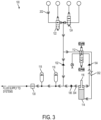
- FIGURE 3 is a system configured to stroke the supercharge cylinder 114 according to one embodiment of the claimed invention.
- the supercharge control valve 112 may open to allow the pressure 202 to propagate to pressure 302 to the supercharge cylinder 114 and advance the piston 116 in the cylinder 114.
- the valve 106 may be open such that as the piston 116 advances upward, pressure is increased in the fluid above a bottom surface of the piston 116.
- the increased pressure in the cylinder 114 may result in increased pressure 304 in the hydraulic lines of the subsea system.
- the valve 104 may be closed to prevent exit of pressure from the input of the supercharge cylinder 114 forcing the increased pressure to the accumulators 118.
- the accumulators 118 and other subsea equipment may operate at a pressure above base control system pressure.
- multiple superchargers 114 or accumulators 118 may be configured to achieve fixed steps in the increased base control system pressure, such as 34, 52 and 69 MPa (5000, 7500, and 10000 psi).
- a single accumulator may be charged and regulated to provide the fixed steps in the increased base control system pressure.
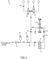
- FIGURE 4 is a system configured to stroke the supercharge cylinder to fill with new fluid according to one embodiment of the claimed invention.
- the valves 112 and 104 may open to allow the pressure 202 to propagate to the supercharge cylinder 114.
- the valve 106 may close, and the pressure 202 propagates to pressure 402 to return the piston 116 to a bottom position of the cylinder 114.
- the pressure 202 may continue to propagate to the pressure 406 to operate subsea equipment and maintain the accumulators 118 at base control system pressure.
- the supercharge cylinder 114 allows increased pressure above base control system pressure at the accumulators 118 and other subsea equipment attached to hydraulic lines of the subsea system.
- FIGURE 5 is a flow chart illustrating one method of supercharging a hydraulic system according to one example not falling within the scope of the claimed method.
- Increased pressure in a hydraulic system may be achieved through the method 500, which begins at block 502 with charging accumulators to a base control system pressure.
- a supercharge cylinder is stroked to increase accumulator pressure above a base control system pressure.
- the supercharge cylinder is stroked in to fill a supercharge chamber of the supercharge cylinder with new fluid. Operation of a system with a supercharger cylinder as described in blocks 502, 504, and 506 are generally described with respect to a particular system shown in FIGURE 2 , FIGURE 3 , and FIGURE 4 .
- FIGURE 6 is a schematic illustrating a system configured to provide feedback regarding a supercharged pressure according to one embodiment of the claimed invention.
- a control module 602 may receive information from a pressure sensor 632 coupled to a line coupled to the accumulator 118 and/or coupled to a high pressure side of the supercharge cylinder 114.
- a deintensifier 612 may couple the pressure sensor 632 to the line coupled to the accumulator 118.
- the deintensifier 612 may provide an output pressure to the sensor 632 at a fixed ratio or fixed offset from the pressure in the line coupled to the accumulator 118, which allows the pressure sensor 632 to be a low pressure sensor 632.
- a pressure readout 616 and an isolation valve 614 may also be coupled to the pressure sensor 632 to allow a manual readout of the pressure.
- the pressure sensor 632 and related components 622 may be located in a first module, such as a module on a the surface at a ship or drilling rig.
- the supercharge cylinder 114 and related components 620 may be located subsea, such as near a blowout preventer (BOP). In another embodiment, the components 622 may be located subsea, such as near the blowout preventer (BOP).
- a control module 602 may be coupled to the pressure sensor 632 and to the supercharge cylinder control valve 112.
- the control module 602 may execute algorithms for controlling the supercharge cylinder control valve 112 based on, for example, input from the pressure sensor 632 to obtain a desired pressure in the accumulators 118.
- FIGURE 7 is a flow chart illustrating one method of supercharging a hydraulic system to a desired pressure using feedback from the supercharger according to one example not falling within the scope of the claimed method.
- a method 700 begins at block 702 with charging accumulators from the surface.
- a reference pressure may be 21 or 34 MPa (3000 or 5000 psi). If not, the method 700 returns to block 702 to continue charging the accumulators from the surface. If the system pressure is approximately equal to the reference pressure, then the method 700 proceeds to block 706.
- the supercharger is activated for one stroke of the supercharger cylinder to increase the system pressure.
- a delay time may be implemented.
- the supercharger may be activated for one stroke to refill the supercharge cylinder.
- the method 700 may proceed to performing a function with the hydraulic pressure at the desired pressure.
- Block 712 may not be performed immediately when the desired pressure is obtained. That is, the desired pressure may be stored in the accumulators until an emergency occurs that requires actuation of components using the stored pressure.
- the actuation of components at block 712 may be the actuation of a ram to shear a drillpipe.
- Higher pressures within the accumulators allow for larger and/or thicker drillpipe to be cut with the same shears.
- FIGURE 8 is a graph illustrating increased pressure obtained at an end of a ram with one supercharged pressure according to one embodiment of the claimed invention.
- the graph of FIGURE 8 shows lines 802 and 804 demonstrating a pressure drop as the volume of fluid in the accumulators drops due to consumption in operation of the ram.
- Marks 822, 824, 826, and 828 are the pressures required at the end of the ram to shear certain drillpipes.
- the mark 824 may mark a pressure required to shear a larger drill pipe than the drill pipe corresponding to mark 822.
- the line 802 illustrates that the pressure decreases as fluid is consumed such that the pipe 822 may be sheared but the pipes 824, 826, and 828 are not sheared. That is, the accumulator with 21 MPa (3000 psi) contains insufficient pressure to operate the ram to cut drillpipes requiring pressure of marks 824, 826, and 828.
- the line 804 illustrates that the pressure decreases as fluid is consumed such that pipes requiring pressures 826 and 828 are not sheared.
- a pressure regulator may be set to limit the output of the accumulators to a regulated pressure 810.
- an output of the fluid for use by subsea systems may have a fixed pressure as fluid volume initially drops.
- the line 806 illustrates that the increased pressure through the use of the supercharge cylinder allows the drill pipe corresponding to pressure 826 to be sheared.
- FIGURE 9 is a graph illustrating increased pressure obtained at an end of a ram with another supercharged pressure according to one embodiment of the claimed invention.
- Lines 906 and 908 illustrate an initial pressure obtained of 69 MPa (10000 psi) that may allow shearing of drill pipe corresponding to the pressure 828.
- the higher pressures achieved with the supercharge cylinder may improve the response of hydraulic systems in a blowout preventer (BOP), such as emergency response systems to cut and/or seal a drillpipe.
- BOP blowout preventer
- the higher pressures may increase the diameter or thickness of pipe that may be cut and/or sealed by the BOP.
- the increased pressure achieved with the supercharge cylinder may provide additional hydraulic fluid for operating these hydraulic systems without increasing a number of accumulators already present at the BOP.
- a supercharge cylinder may be added onto existing BOP infrastructure to increase the capability of the existing BOP infrastructure.
- Computer-readable media includes physical computer storage media.
- a storage medium may be any available medium that can be accessed by a computer.
- such computer-readable media can comprise RAM, ROM, EEPROM, CD-ROM or other optical disk storage, magnetic disk storage or other magnetic storage devices, or any other medium that can be used to store desired program code in the form of instructions or data structures and that can be accessed by a computer.
- Disk and disc includes compact discs (CD), laser discs, optical discs, digital versatile discs (DVD), floppy disks and blu-ray discs. Generally, disks reproduce data magnetically, and discs reproduce data optically. Combinations of the above should also be included within the scope of computer-readable media.
- instructions and/or data may be provided as signals on transmission media included in a communication apparatus.
- a communication apparatus may include a transceiver having signals indicative of instructions and data. The instructions and data are configured to cause one or more processors to implement the functions outlined in the claims.
Landscapes
- Engineering & Computer Science (AREA)
- Fluid Mechanics (AREA)
- Physics & Mathematics (AREA)
- Mining & Mineral Resources (AREA)
- Life Sciences & Earth Sciences (AREA)
- Geology (AREA)
- Mechanical Engineering (AREA)
- General Engineering & Computer Science (AREA)
- Environmental & Geological Engineering (AREA)
- General Life Sciences & Earth Sciences (AREA)
- Geochemistry & Mineralogy (AREA)
- Fluid-Pressure Circuits (AREA)
- Supply Devices, Intensifiers, Converters, And Telemotors (AREA)
- Filling Or Discharging Of Gas Storage Vessels (AREA)
Applications Claiming Priority (2)
| Application Number | Priority Date | Filing Date | Title |
|---|---|---|---|
| US201361800862P | 2013-03-15 | 2013-03-15 | |
| PCT/US2014/029516 WO2014144916A2 (en) | 2013-03-15 | 2014-03-14 | Supercharging pressure in a subsea well system |
Publications (3)
| Publication Number | Publication Date |
|---|---|
| EP2971453A2 EP2971453A2 (en) | 2016-01-20 |
| EP2971453A4 EP2971453A4 (en) | 2017-05-10 |
| EP2971453B1 true EP2971453B1 (en) | 2025-05-07 |
Family
ID=51522318
Family Applications (1)
| Application Number | Title | Priority Date | Filing Date |
|---|---|---|---|
| EP14764354.8A Active EP2971453B1 (en) | 2013-03-15 | 2014-03-14 | Supercharging pressure in a subsea well system |
Country Status (7)
| Country | Link |
|---|---|
| US (1) | US10240430B2 (https=) |
| EP (1) | EP2971453B1 (https=) |
| CN (1) | CN105392959B (https=) |
| BR (1) | BR112015023605B1 (https=) |
| CA (1) | CA2907279C (https=) |
| HK (1) | HK1219769A1 (https=) |
| WO (1) | WO2014144916A2 (https=) |
Families Citing this family (7)
| Publication number | Priority date | Publication date | Assignee | Title |
|---|---|---|---|---|
| US10132135B2 (en) | 2015-08-05 | 2018-11-20 | Cameron International Corporation | Subsea drilling system with intensifier |
| CN106761502B (zh) * | 2017-03-10 | 2023-11-17 | 南阳市亚华石油机械有限公司 | 液动泥浆闸阀控制装置 |
| CN111319203A (zh) * | 2018-12-17 | 2020-06-23 | 恩格尔机械(上海)有限公司 | 塑料成型机以及用于运行塑料成型机的方法 |
| US11401954B2 (en) | 2020-01-03 | 2022-08-02 | The Oilgear Company | Subsea hydraulic pressure boosting and regulating system |
| US12091929B2 (en) * | 2022-09-19 | 2024-09-17 | Trendsetter Engineering, Inc. | Subsea grease injection system |
| NO348725B1 (en) * | 2023-04-25 | 2025-05-12 | TechnipFMC Norge AS | System and method for testing equipment |
| CN117287140A (zh) * | 2023-10-31 | 2023-12-26 | 河北新铁虎石油机械有限公司 | 带剪切压力放大器的地面防喷器控制装置及控制方法 |
Family Cites Families (20)
| Publication number | Priority date | Publication date | Assignee | Title |
|---|---|---|---|---|
| IT1073144B (it) | 1976-10-28 | 1985-04-13 | Welko Ind Spa | Apparecchiatura idraulica per l'alimentazione di liquido a due differenti pressioni ad un dispositivo idraulico |
| JPS53102183U (https=) | 1977-01-24 | 1978-08-17 | ||
| US4555220A (en) | 1979-11-07 | 1985-11-26 | Towler Hydraulics, Inc. | Regeneration system for a hydraulic intensifier unit |
| JPS6339799A (ja) | 1986-08-05 | 1988-02-20 | ダイキン工業株式会社 | 切断装置 |
| JP2665556B2 (ja) | 1988-07-29 | 1997-10-22 | オ−クマ株式会社 | 増圧回路付流体圧クランプ装置 |
| JPH0777205A (ja) * | 1993-09-10 | 1995-03-20 | Shin Caterpillar Mitsubishi Ltd | 増圧装置 |
| EP1270870B1 (en) | 2001-06-22 | 2006-08-16 | Cooper Cameron Corporation | Blow out preventer testing apparatus |
| DE60301150T2 (de) * | 2002-02-01 | 2006-01-05 | Vetco Gray Controls Ltd., Nailsea | Linearantrieb |
| US7137450B2 (en) * | 2004-02-18 | 2006-11-21 | Fmc Technologies, Inc. | Electric-hydraulic power unit |
| US7159662B2 (en) * | 2004-02-18 | 2007-01-09 | Fmc Technologies, Inc. | System for controlling a hydraulic actuator, and methods of using same |
| US7424917B2 (en) * | 2005-03-23 | 2008-09-16 | Varco I/P, Inc. | Subsea pressure compensation system |
| WO2006124024A1 (en) * | 2005-05-13 | 2006-11-23 | Welldynamics, Inc. | Single line control module for well tool actuation |
| GB0520878D0 (en) * | 2005-10-14 | 2005-11-23 | Stamper Eric S | Improved pump |
| NO332404B1 (no) * | 2007-06-01 | 2012-09-10 | Fmc Kongsberg Subsea As | Fremgangsmate og innretning for redusering av et trykk i en forste kavitet i en undersjoisk anordning |
| GB2461061A (en) | 2008-06-19 | 2009-12-23 | Vetco Gray Controls Ltd | Subsea hydraulic intensifier with supply directional control valves electronically switched |
| US20100084588A1 (en) * | 2008-10-07 | 2010-04-08 | Diamond Offshore Drilling, Inc. | Deepwater Hydraulic Control System |
| ITMO20100044A1 (it) * | 2010-02-26 | 2011-08-27 | De Hieronymis Carlo Maria Rozzi | Intensificatore di forza idraulica a riarmo con mantenimento della posizione raggiunta e della forza di spinta ottenuta durante ogni fase di riarmo |
| US8387706B2 (en) * | 2010-05-20 | 2013-03-05 | Reel Power Licensing Corp | Negative accumulator for BOP shear rams |
| BR112013027597A2 (pt) * | 2011-04-26 | 2017-02-14 | Bp Corp North America Inc | sistema acumulador submarino |
| CN102383769A (zh) * | 2011-10-14 | 2012-03-21 | 上海大学 | 动力补偿式液压增压注水系统 |
-
2014
- 2014-03-14 BR BR112015023605-7A patent/BR112015023605B1/pt active IP Right Grant
- 2014-03-14 HK HK16107778.5A patent/HK1219769A1/zh unknown
- 2014-03-14 US US14/213,934 patent/US10240430B2/en active Active
- 2014-03-14 CA CA2907279A patent/CA2907279C/en active Active
- 2014-03-14 EP EP14764354.8A patent/EP2971453B1/en active Active
- 2014-03-14 WO PCT/US2014/029516 patent/WO2014144916A2/en not_active Ceased
- 2014-03-14 CN CN201480027743.6A patent/CN105392959B/zh not_active Expired - Fee Related
Also Published As
| Publication number | Publication date |
|---|---|
| WO2014144916A3 (en) | 2015-05-21 |
| WO2014144916A2 (en) | 2014-09-18 |
| CN105392959B (zh) | 2019-11-15 |
| CA2907279A1 (en) | 2014-09-18 |
| BR112015023605A2 (https=) | 2017-08-22 |
| CN105392959A (zh) | 2016-03-09 |
| EP2971453A2 (en) | 2016-01-20 |
| CA2907279C (en) | 2021-05-11 |
| US20140262308A1 (en) | 2014-09-18 |
| HK1219769A1 (zh) | 2017-04-13 |
| EP2971453A4 (en) | 2017-05-10 |
| US10240430B2 (en) | 2019-03-26 |
| BR112015023605B1 (pt) | 2022-07-05 |
Similar Documents
| Publication | Publication Date | Title |
|---|---|---|
| EP2971453B1 (en) | Supercharging pressure in a subsea well system | |
| EP2199535B1 (en) | Subsea force generating device and method | |
| US8651190B2 (en) | Shear boost triggering and bottle reducing system and method | |
| CN104145077B (zh) | 水下减压系统 | |
| US8464525B2 (en) | Subsea power fluid recovery systems | |
| AU2008257712B2 (en) | Control system | |
| US10132135B2 (en) | Subsea drilling system with intensifier | |
| US20100084588A1 (en) | Deepwater Hydraulic Control System | |
| EP1863701A1 (en) | Apparatus and method for compensating for subsea pressure on a hydraulic circuit | |
| AU2009245885A1 (en) | Rechargeable subsea force generating device and method | |
| EP3004532B1 (en) | Propellant driven accumulator | |
| WO2015164314A1 (en) | Subsea accumulator | |
| WO2015171842A1 (en) | Subsea force generating device and method | |
| US11506226B2 (en) | Hybrid hydraulic accumulator | |
| Lazar et al. | Emergency Supply of Subsea High Pressure Control Fluid Six Shooter |
Legal Events
| Date | Code | Title | Description |
|---|---|---|---|
| PUAI | Public reference made under article 153(3) epc to a published international application that has entered the european phase |
Free format text: ORIGINAL CODE: 0009012 |
|
| 17P | Request for examination filed |
Effective date: 20151007 |
|
| AK | Designated contracting states |
Kind code of ref document: A2 Designated state(s): AL AT BE BG CH CY CZ DE DK EE ES FI FR GB GR HR HU IE IS IT LI LT LU LV MC MK MT NL NO PL PT RO RS SE SI SK SM TR |
|
| AX | Request for extension of the european patent |
Extension state: BA ME |
|
| DAX | Request for extension of the european patent (deleted) | ||
| RIC1 | Information provided on ipc code assigned before grant |
Ipc: F15B 1/027 20060101ALI20161118BHEP Ipc: E21B 47/06 20120101ALI20161118BHEP Ipc: E21B 33/035 20060101ALI20161118BHEP Ipc: F15B 11/032 20060101ALI20161118BHEP Ipc: E21B 21/00 20060101AFI20161118BHEP |
|
| REG | Reference to a national code |
Ref country code: HK Ref legal event code: DE Ref document number: 1219769 Country of ref document: HK |
|
| A4 | Supplementary search report drawn up and despatched |
Effective date: 20170410 |
|
| RIC1 | Information provided on ipc code assigned before grant |
Ipc: F15B 1/027 20060101ALI20170404BHEP Ipc: E21B 21/00 20060101AFI20170404BHEP Ipc: F15B 11/032 20060101ALI20170404BHEP Ipc: E21B 47/06 20120101ALI20170404BHEP Ipc: E21B 33/035 20060101ALI20170404BHEP |
|
| STAA | Information on the status of an ep patent application or granted ep patent |
Free format text: STATUS: REQUEST FOR EXAMINATION WAS MADE |
|
| RAP1 | Party data changed (applicant data changed or rights of an application transferred) |
Owner name: TRANSOCEAN SEDCO FOREX VENTURES LIMITED |
|
| STAA | Information on the status of an ep patent application or granted ep patent |
Free format text: STATUS: EXAMINATION IS IN PROGRESS |
|
| 17Q | First examination report despatched |
Effective date: 20200702 |
|
| REG | Reference to a national code |
Ref country code: HK Ref legal event code: WD Ref document number: 1219769 Country of ref document: HK |
|
| GRAP | Despatch of communication of intention to grant a patent |
Free format text: ORIGINAL CODE: EPIDOSNIGR1 |
|
| STAA | Information on the status of an ep patent application or granted ep patent |
Free format text: STATUS: GRANT OF PATENT IS INTENDED |
|
| INTG | Intention to grant announced |
Effective date: 20241008 |
|
| GRAS | Grant fee paid |
Free format text: ORIGINAL CODE: EPIDOSNIGR3 |
|
| P01 | Opt-out of the competence of the unified patent court (upc) registered |
Free format text: CASE NUMBER: APP_7905/2025 Effective date: 20250217 |
|
| RAP3 | Party data changed (applicant data changed or rights of an application transferred) |
Owner name: TRANSOCEAN SEDCO FOREX VENTURES LIMITED |
|
| GRAA | (expected) grant |
Free format text: ORIGINAL CODE: 0009210 |
|
| STAA | Information on the status of an ep patent application or granted ep patent |
Free format text: STATUS: THE PATENT HAS BEEN GRANTED |
|
| AK | Designated contracting states |
Kind code of ref document: B1 Designated state(s): AL AT BE BG CH CY CZ DE DK EE ES FI FR GB GR HR HU IE IS IT LI LT LU LV MC MK MT NL NO PL PT RO RS SE SI SK SM TR |
|
| REG | Reference to a national code |
Ref country code: GB Ref legal event code: FG4D |
|
| REG | Reference to a national code |
Ref country code: CH Ref legal event code: EP |
|
| REG | Reference to a national code |
Ref country code: DE Ref legal event code: R096 Ref document number: 602014091895 Country of ref document: DE |
|
| REG | Reference to a national code |
Ref country code: IE Ref legal event code: FG4D |
|
| REG | Reference to a national code |
Ref country code: NL Ref legal event code: MP Effective date: 20250507 |
|
| PG25 | Lapsed in a contracting state [announced via postgrant information from national office to epo] |
Ref country code: FI Free format text: LAPSE BECAUSE OF FAILURE TO SUBMIT A TRANSLATION OF THE DESCRIPTION OR TO PAY THE FEE WITHIN THE PRESCRIBED TIME-LIMIT Effective date: 20250507 Ref country code: ES Free format text: LAPSE BECAUSE OF FAILURE TO SUBMIT A TRANSLATION OF THE DESCRIPTION OR TO PAY THE FEE WITHIN THE PRESCRIBED TIME-LIMIT Effective date: 20250507 Ref country code: PT Free format text: LAPSE BECAUSE OF FAILURE TO SUBMIT A TRANSLATION OF THE DESCRIPTION OR TO PAY THE FEE WITHIN THE PRESCRIBED TIME-LIMIT Effective date: 20250908 |
|
| REG | Reference to a national code |
Ref country code: LT Ref legal event code: MG9D |
|
| PG25 | Lapsed in a contracting state [announced via postgrant information from national office to epo] |
Ref country code: GR Free format text: LAPSE BECAUSE OF FAILURE TO SUBMIT A TRANSLATION OF THE DESCRIPTION OR TO PAY THE FEE WITHIN THE PRESCRIBED TIME-LIMIT Effective date: 20250808 |
|
| PG25 | Lapsed in a contracting state [announced via postgrant information from national office to epo] |
Ref country code: PL Free format text: LAPSE BECAUSE OF FAILURE TO SUBMIT A TRANSLATION OF THE DESCRIPTION OR TO PAY THE FEE WITHIN THE PRESCRIBED TIME-LIMIT Effective date: 20250507 Ref country code: NL Free format text: LAPSE BECAUSE OF FAILURE TO SUBMIT A TRANSLATION OF THE DESCRIPTION OR TO PAY THE FEE WITHIN THE PRESCRIBED TIME-LIMIT Effective date: 20250507 |
|
| REG | Reference to a national code |
Ref country code: AT Ref legal event code: MK05 Ref document number: 1792653 Country of ref document: AT Kind code of ref document: T Effective date: 20250507 |
|
| PG25 | Lapsed in a contracting state [announced via postgrant information from national office to epo] |
Ref country code: BG Free format text: LAPSE BECAUSE OF FAILURE TO SUBMIT A TRANSLATION OF THE DESCRIPTION OR TO PAY THE FEE WITHIN THE PRESCRIBED TIME-LIMIT Effective date: 20250507 |
|
| PG25 | Lapsed in a contracting state [announced via postgrant information from national office to epo] |
Ref country code: HR Free format text: LAPSE BECAUSE OF FAILURE TO SUBMIT A TRANSLATION OF THE DESCRIPTION OR TO PAY THE FEE WITHIN THE PRESCRIBED TIME-LIMIT Effective date: 20250507 |
|
| PG25 | Lapsed in a contracting state [announced via postgrant information from national office to epo] |
Ref country code: AT Free format text: LAPSE BECAUSE OF FAILURE TO SUBMIT A TRANSLATION OF THE DESCRIPTION OR TO PAY THE FEE WITHIN THE PRESCRIBED TIME-LIMIT Effective date: 20250507 |
|
| PG25 | Lapsed in a contracting state [announced via postgrant information from national office to epo] |
Ref country code: RS Free format text: LAPSE BECAUSE OF FAILURE TO SUBMIT A TRANSLATION OF THE DESCRIPTION OR TO PAY THE FEE WITHIN THE PRESCRIBED TIME-LIMIT Effective date: 20250807 |
|
| PG25 | Lapsed in a contracting state [announced via postgrant information from national office to epo] |
Ref country code: IS Free format text: LAPSE BECAUSE OF FAILURE TO SUBMIT A TRANSLATION OF THE DESCRIPTION OR TO PAY THE FEE WITHIN THE PRESCRIBED TIME-LIMIT Effective date: 20250907 |
|
| PG25 | Lapsed in a contracting state [announced via postgrant information from national office to epo] |
Ref country code: LV Free format text: LAPSE BECAUSE OF FAILURE TO SUBMIT A TRANSLATION OF THE DESCRIPTION OR TO PAY THE FEE WITHIN THE PRESCRIBED TIME-LIMIT Effective date: 20250507 |
|
| PG25 | Lapsed in a contracting state [announced via postgrant information from national office to epo] |
Ref country code: DK Free format text: LAPSE BECAUSE OF FAILURE TO SUBMIT A TRANSLATION OF THE DESCRIPTION OR TO PAY THE FEE WITHIN THE PRESCRIBED TIME-LIMIT Effective date: 20250507 Ref country code: SM Free format text: LAPSE BECAUSE OF FAILURE TO SUBMIT A TRANSLATION OF THE DESCRIPTION OR TO PAY THE FEE WITHIN THE PRESCRIBED TIME-LIMIT Effective date: 20250507 |
|
| PG25 | Lapsed in a contracting state [announced via postgrant information from national office to epo] |
Ref country code: CZ Free format text: LAPSE BECAUSE OF FAILURE TO SUBMIT A TRANSLATION OF THE DESCRIPTION OR TO PAY THE FEE WITHIN THE PRESCRIBED TIME-LIMIT Effective date: 20250507 |
|
| PG25 | Lapsed in a contracting state [announced via postgrant information from national office to epo] |
Ref country code: EE Free format text: LAPSE BECAUSE OF FAILURE TO SUBMIT A TRANSLATION OF THE DESCRIPTION OR TO PAY THE FEE WITHIN THE PRESCRIBED TIME-LIMIT Effective date: 20250507 |
|
| PG25 | Lapsed in a contracting state [announced via postgrant information from national office to epo] |
Ref country code: RO Free format text: LAPSE BECAUSE OF FAILURE TO SUBMIT A TRANSLATION OF THE DESCRIPTION OR TO PAY THE FEE WITHIN THE PRESCRIBED TIME-LIMIT Effective date: 20250507 Ref country code: SK Free format text: LAPSE BECAUSE OF FAILURE TO SUBMIT A TRANSLATION OF THE DESCRIPTION OR TO PAY THE FEE WITHIN THE PRESCRIBED TIME-LIMIT Effective date: 20250507 |
|
| PG25 | Lapsed in a contracting state [announced via postgrant information from national office to epo] |
Ref country code: IT Free format text: LAPSE BECAUSE OF FAILURE TO SUBMIT A TRANSLATION OF THE DESCRIPTION OR TO PAY THE FEE WITHIN THE PRESCRIBED TIME-LIMIT Effective date: 20250507 |
|
| REG | Reference to a national code |
Ref country code: DE Ref legal event code: R097 Ref document number: 602014091895 Country of ref document: DE |
|
| PLBE | No opposition filed within time limit |
Free format text: ORIGINAL CODE: 0009261 |
|
| STAA | Information on the status of an ep patent application or granted ep patent |
Free format text: STATUS: NO OPPOSITION FILED WITHIN TIME LIMIT |
|
| REG | Reference to a national code |
Ref country code: CH Ref legal event code: L10 Free format text: ST27 STATUS EVENT CODE: U-0-0-L10-L00 (AS PROVIDED BY THE NATIONAL OFFICE) Effective date: 20260318 |
|
| PGFP | Annual fee paid to national office [announced via postgrant information from national office to epo] |
Ref country code: GB Payment date: 20260327 Year of fee payment: 13 |
|
| PGFP | Annual fee paid to national office [announced via postgrant information from national office to epo] |
Ref country code: NO Payment date: 20260327 Year of fee payment: 13 |
|
| 26N | No opposition filed |
Effective date: 20260210 |