EP2969972B1 - Methods of inhibiting fouling in liquid systems - Google Patents
Methods of inhibiting fouling in liquid systems Download PDFInfo
- Publication number
- EP2969972B1 EP2969972B1 EP14768925.1A EP14768925A EP2969972B1 EP 2969972 B1 EP2969972 B1 EP 2969972B1 EP 14768925 A EP14768925 A EP 14768925A EP 2969972 B1 EP2969972 B1 EP 2969972B1
- Authority
- EP
- European Patent Office
- Prior art keywords
- biocide
- filtration
- stream
- filtration surface
- aqueous liquid
- Prior art date
- Legal status (The legal status is an assumption and is not a legal conclusion. Google has not performed a legal analysis and makes no representation as to the accuracy of the status listed.)
- Active
Links
Images


Classifications
-
- C—CHEMISTRY; METALLURGY
- C02—TREATMENT OF WATER, WASTE WATER, SEWAGE, OR SLUDGE
- C02F—TREATMENT OF WATER, WASTE WATER, SEWAGE, OR SLUDGE
- C02F1/00—Treatment of water, waste water, or sewage
- C02F1/50—Treatment of water, waste water, or sewage by addition or application of a germicide or by oligodynamic treatment
-
- B—PERFORMING OPERATIONS; TRANSPORTING
- B01—PHYSICAL OR CHEMICAL PROCESSES OR APPARATUS IN GENERAL
- B01D—SEPARATION
- B01D37/00—Processes of filtration
- B01D37/04—Controlling the filtration
-
- B—PERFORMING OPERATIONS; TRANSPORTING
- B01—PHYSICAL OR CHEMICAL PROCESSES OR APPARATUS IN GENERAL
- B01D—SEPARATION
- B01D37/00—Processes of filtration
- B01D37/04—Controlling the filtration
- B01D37/041—Controlling the filtration by clearness or turbidity measuring
-
- C—CHEMISTRY; METALLURGY
- C02—TREATMENT OF WATER, WASTE WATER, SEWAGE, OR SLUDGE
- C02F—TREATMENT OF WATER, WASTE WATER, SEWAGE, OR SLUDGE
- C02F1/00—Treatment of water, waste water, or sewage
- C02F1/001—Processes for the treatment of water whereby the filtration technique is of importance
-
- C—CHEMISTRY; METALLURGY
- C02—TREATMENT OF WATER, WASTE WATER, SEWAGE, OR SLUDGE
- C02F—TREATMENT OF WATER, WASTE WATER, SEWAGE, OR SLUDGE
- C02F1/00—Treatment of water, waste water, or sewage
- C02F1/008—Control or steering systems not provided for elsewhere in subclass C02F
-
- B—PERFORMING OPERATIONS; TRANSPORTING
- B01—PHYSICAL OR CHEMICAL PROCESSES OR APPARATUS IN GENERAL
- B01D—SEPARATION
- B01D2201/00—Details relating to filtering apparatus
- B01D2201/54—Computerised or programmable systems
-
- B—PERFORMING OPERATIONS; TRANSPORTING
- B01—PHYSICAL OR CHEMICAL PROCESSES OR APPARATUS IN GENERAL
- B01D—SEPARATION
- B01D2201/00—Details relating to filtering apparatus
- B01D2201/56—Wireless systems for monitoring the filter
-
- C—CHEMISTRY; METALLURGY
- C02—TREATMENT OF WATER, WASTE WATER, SEWAGE, OR SLUDGE
- C02F—TREATMENT OF WATER, WASTE WATER, SEWAGE, OR SLUDGE
- C02F1/00—Treatment of water, waste water, or sewage
- C02F1/30—Treatment of water, waste water, or sewage by irradiation
- C02F1/32—Treatment of water, waste water, or sewage by irradiation with ultraviolet light
-
- C—CHEMISTRY; METALLURGY
- C02—TREATMENT OF WATER, WASTE WATER, SEWAGE, OR SLUDGE
- C02F—TREATMENT OF WATER, WASTE WATER, SEWAGE, OR SLUDGE
- C02F1/00—Treatment of water, waste water, or sewage
- C02F1/72—Treatment of water, waste water, or sewage by oxidation
-
- C—CHEMISTRY; METALLURGY
- C02—TREATMENT OF WATER, WASTE WATER, SEWAGE, OR SLUDGE
- C02F—TREATMENT OF WATER, WASTE WATER, SEWAGE, OR SLUDGE
- C02F1/00—Treatment of water, waste water, or sewage
- C02F1/72—Treatment of water, waste water, or sewage by oxidation
- C02F1/722—Oxidation by peroxides
-
- C—CHEMISTRY; METALLURGY
- C02—TREATMENT OF WATER, WASTE WATER, SEWAGE, OR SLUDGE
- C02F—TREATMENT OF WATER, WASTE WATER, SEWAGE, OR SLUDGE
- C02F1/00—Treatment of water, waste water, or sewage
- C02F1/72—Treatment of water, waste water, or sewage by oxidation
- C02F1/76—Treatment of water, waste water, or sewage by oxidation with halogens or compounds of halogens
-
- C—CHEMISTRY; METALLURGY
- C02—TREATMENT OF WATER, WASTE WATER, SEWAGE, OR SLUDGE
- C02F—TREATMENT OF WATER, WASTE WATER, SEWAGE, OR SLUDGE
- C02F1/00—Treatment of water, waste water, or sewage
- C02F1/72—Treatment of water, waste water, or sewage by oxidation
- C02F1/76—Treatment of water, waste water, or sewage by oxidation with halogens or compounds of halogens
- C02F1/766—Treatment of water, waste water, or sewage by oxidation with halogens or compounds of halogens by means of halogens other than chlorine or of halogenated compounds containing halogen other than chlorine
-
- C—CHEMISTRY; METALLURGY
- C02—TREATMENT OF WATER, WASTE WATER, SEWAGE, OR SLUDGE
- C02F—TREATMENT OF WATER, WASTE WATER, SEWAGE, OR SLUDGE
- C02F1/00—Treatment of water, waste water, or sewage
- C02F1/72—Treatment of water, waste water, or sewage by oxidation
- C02F1/78—Treatment of water, waste water, or sewage by oxidation with ozone
-
- C—CHEMISTRY; METALLURGY
- C02—TREATMENT OF WATER, WASTE WATER, SEWAGE, OR SLUDGE
- C02F—TREATMENT OF WATER, WASTE WATER, SEWAGE, OR SLUDGE
- C02F2103/00—Nature of the water, waste water, sewage or sludge to be treated
- C02F2103/02—Non-contaminated water, e.g. for industrial water supply
- C02F2103/023—Water in cooling circuits
-
- C—CHEMISTRY; METALLURGY
- C02—TREATMENT OF WATER, WASTE WATER, SEWAGE, OR SLUDGE
- C02F—TREATMENT OF WATER, WASTE WATER, SEWAGE, OR SLUDGE
- C02F2209/00—Controlling or monitoring parameters in water treatment
- C02F2209/003—Downstream control, i.e. outlet monitoring, e.g. to check the treating agents, such as halogens or ozone, leaving the process
-
- C—CHEMISTRY; METALLURGY
- C02—TREATMENT OF WATER, WASTE WATER, SEWAGE, OR SLUDGE
- C02F—TREATMENT OF WATER, WASTE WATER, SEWAGE, OR SLUDGE
- C02F2209/00—Controlling or monitoring parameters in water treatment
- C02F2209/005—Processes using a programmable logic controller [PLC]
-
- C—CHEMISTRY; METALLURGY
- C02—TREATMENT OF WATER, WASTE WATER, SEWAGE, OR SLUDGE
- C02F—TREATMENT OF WATER, WASTE WATER, SEWAGE, OR SLUDGE
- C02F2209/00—Controlling or monitoring parameters in water treatment
- C02F2209/03—Pressure
-
- C—CHEMISTRY; METALLURGY
- C02—TREATMENT OF WATER, WASTE WATER, SEWAGE, OR SLUDGE
- C02F—TREATMENT OF WATER, WASTE WATER, SEWAGE, OR SLUDGE
- C02F2209/00—Controlling or monitoring parameters in water treatment
- C02F2209/04—Oxidation reduction potential [ORP]
-
- C—CHEMISTRY; METALLURGY
- C02—TREATMENT OF WATER, WASTE WATER, SEWAGE, OR SLUDGE
- C02F—TREATMENT OF WATER, WASTE WATER, SEWAGE, OR SLUDGE
- C02F2209/00—Controlling or monitoring parameters in water treatment
- C02F2209/11—Turbidity
-
- C—CHEMISTRY; METALLURGY
- C02—TREATMENT OF WATER, WASTE WATER, SEWAGE, OR SLUDGE
- C02F—TREATMENT OF WATER, WASTE WATER, SEWAGE, OR SLUDGE
- C02F2209/00—Controlling or monitoring parameters in water treatment
- C02F2209/40—Liquid flow rate
-
- C—CHEMISTRY; METALLURGY
- C02—TREATMENT OF WATER, WASTE WATER, SEWAGE, OR SLUDGE
- C02F—TREATMENT OF WATER, WASTE WATER, SEWAGE, OR SLUDGE
- C02F2301/00—General aspects of water treatment
- C02F2301/04—Flow arrangements
- C02F2301/043—Treatment of partial or bypass streams
-
- C—CHEMISTRY; METALLURGY
- C02—TREATMENT OF WATER, WASTE WATER, SEWAGE, OR SLUDGE
- C02F—TREATMENT OF WATER, WASTE WATER, SEWAGE, OR SLUDGE
- C02F2301/00—General aspects of water treatment
- C02F2301/04—Flow arrangements
- C02F2301/046—Recirculation with an external loop
-
- C—CHEMISTRY; METALLURGY
- C02—TREATMENT OF WATER, WASTE WATER, SEWAGE, OR SLUDGE
- C02F—TREATMENT OF WATER, WASTE WATER, SEWAGE, OR SLUDGE
- C02F2303/00—Specific treatment goals
- C02F2303/20—Prevention of biofouling
-
- C—CHEMISTRY; METALLURGY
- C02—TREATMENT OF WATER, WASTE WATER, SEWAGE, OR SLUDGE
- C02F—TREATMENT OF WATER, WASTE WATER, SEWAGE, OR SLUDGE
- C02F2305/00—Use of specific compounds during water treatment
- C02F2305/02—Specific form of oxidant
Definitions
- the disclosure is directed to methods of inhibiting fouling in liquid systems by using biocides and filtration techniques.
- Fouling has a negative impact on the industrial water system.
- severe mineral scale i.e., inorganic material
- Scale on an industrial water system surface presents an ideal environment for the growth of microorganisms.
- the presence of microorganisms poses an additional challenge to water treatment of the industrial water system, as biocides, scale inhibitors, and/or corrosion inhibitors may be necessary to maintain efficient operation of the industrial water system.
- Evaporative cooling water systems are particularly prone to fouling, which can occur via a variety of mechanisms.
- fouling mechanisms include deposition of airborne, water-borne, water-formed, and/or microbiological contaminants; water stagnation; process leaks; and other factors. If fouling is allowed to progress, the industrial water system can suffer from decreased operational efficiency, equipment failure, lack of water quality control, and increased health-related risks associated with microbial fouling.
- microbiological contaminants may cause fouling.
- Non-limiting sources of microbiological (i.e., microbial) contamination are airborne contamination, makeup water, process leaks, and improperly cleaned process equipment. These microbials can establish colonies on any wettable or even semi-wettable surface of the industrial water system. Once microbial counts are present in the bulk water, within a short period of time, more than 99% of the microbes present in the water will be present on all surfaces within biofilms.
- cooling towers are excellent air scrubbers.
- a cooling tower typically flushes airborne contaminants into the water phase. These contaminants can ultimately find their way to the heat exchanger surfaces, where they become deposited, thereby reducing heat transfer.
- Non-limiting examples of such contaminants include particulate matter, organic and inorganic contaminants, oils, process contaminants, microorganisms, and so forth. Suspended matter in the cooling water provides the microorganisms with readily available nourishment for sustaining life and reproduction. It is well established that the presence of inorganic, organic, and microbiological deposits have a detrimental impact on the operational parameters of an industrial cooling system, resulting in reduced efficiency and increased operating cost.
- a filtration system can be used to at least partially remove particulate contaminants and prevent them from reaching concentrations that can adversely impact efficient cooling system operation.
- the filtration system may be a full-flow in line system or a partial flow side stream system.
- the side stream configuration provides particular advantages to the full flow system, such as allowing for a smaller filtration unit and the ability to service off-line while not affecting the cooling process. Generally, the side stream configuration only draws between 2 and 10 percent of the flow as compared to the overall circulation of the cooling system.
- any or a combination of several different types of filters may be utilized for the purpose of filtration, and their use depends on the nature of the water and the level of purification wishing to be attained.
- Non-limiting examples include sand filters, cartridge filters, screen filters, and membrane filters, which may employ ultrafiltration, microfiltration, reverse osmosis, and forward osmosis.
- the water to be cleaned wets and passes through the entire filtration surface, with cleaner water leaving the filtration system as filtrate.
- the filtration surface should be cleaned, thereby restoring performance.
- Methods of cleaning the filtration surface depend on the design of the filtration device. For example, a cartridge filter is not typically cleaned but instead replaced. However, a sand or screen filter will typically undergo a manual or automated backwash cycle to remove the collected contaminants.
- For membrane filters there may be similar chemical or non-chemical based cleaning processes, depending on their design.
- US2013015137 A1 discloses a method of inhibiting microbial fouling in aqueous cooling systems with controlled dosage of biocide and a filtration system.
- the present invention is directed to a method of inhibiting microbial fouling according to claim 1.
- Preferred embodiments of the invention are according to dependent claims 2 to 10.
- the disclosure is directed to a method of inhibiting microbial fouling.
- the method comprises providing an industrial process that contains an aqueous liquid having a biocide demand and a first filtration surface having a given porosity and operating variables selected from the group consisting of backwash count, vacuum count, pressure drop across the first filtration surface, oxidation-reduction potential, and combinations thereof.
- the aqueous liquid is treated with a biocide.
- the biocide demand of the biocide-treated aqueous liquid is determined by monitoring at least one of the operating variables of the first filtration surface.
- a stream of the biocide-treated aqueous liquid is provided and filtered with the first filtration surface to produce a second stream that is initially returned to the industrial process.
- the filtering and returning are continued until a steady state with respect to the first filtration surface is reached. Reaching steady state with respect to the first filtration surface is then identified, whereupon the stream of the biocide-treated aqueous liquid is diverted away from the first filtration surface to a second filtration surface having a lower porosity than the first filtration surface.
- the diverted stream is then filtered with the second filtration surface to produce a third stream, and at least a portion of the third stream is returned to the industrial process.
- the disclosure is directed to a method of inhibiting microbial fouling.
- the method comprises providing an aqueous cooling system that contains an aqueous liquid having a biocide demand.
- the aqueous liquid is treated with a biocide.
- At least a portion of the biocide-treated aqueous liquid is diverted to a first filtration surface having a given porosity, thereby producing a first stream.
- the first stream is filtered with the first filtration surface, thereby producing a second stream.
- At least a portion of the second stream is filtered with a second filtration surface that is less porous than the first filtration surface, thereby producing a third stream.
- the biocide demand of the biocide-treated aqueous liquid is determined by monitoring at least one operating variable for the second filtration surface, the at least one operating variable selected from the group consisting of backwash count, vacuum count, pressure drop across the second filtration surface, oxidation-reduction potential, and combinations thereof. At least a portion of the streams is returned to the aqueous cooling system.
- the disclosure is directed to an automated method of improving efficiency in biocide dosing into a recirculation-type aqueous cooling system.
- the method comprises providing a recirculation-type aqueous cooling system that contains an aqueous liquid having a biocide demand.
- a biocide is dosed into the aqueous liquid at a dosage rate.
- At least a portion of the biocide-dosed aqueous liquid is diverted into a filtration loop thereby creating a filtration loop stream having a filtration loop flow rate within the aqueous cooling system.
- the filtration loop stream is sequentially filtered with at least one set of at least two filtration surfaces thereby creating a filtrate.
- the at least two filtration surfaces are progressively less porous in a downstream direction.
- Each of the at least one set of at least two filtration surfaces has operating variables selected from the group consisting of backwash count, vacuum count, pressure drop across each set of at least two filtration surfaces, oxidation-reduction potential, and combinations thereof.
- the biocide demand of the biocide-treated aqueous liquid is determined either intermittently or continuously by monitoring at least one of the operating variables of the at least one set of at least two filtration surfaces.
- a process parameter based on the determined biocide demand is adjusted.
- the process parameter is selected from the group consisting of the dosage rate of the biocide, the filtration loop flow rate, a quantity of the at least one set of at least two filtration surfaces, and combinations thereof.
- the disclosure is generally directed to filtration techniques useful for reducing or eliminating microbial fouling and/or improving efficiency of biocide dosing into aqueous industrial liquids.
- Application of one or more of the disclosed filtration techniques may be particularly useful for aqueous cooling systems.
- fouling and “contamination” refer to the presence or the deposition of any extraneous or undesirable organic or inorganic material in a water-containing industrial process or onto one or more surfaces within the water-containing industrial process.
- Microbial fouling refers to the presence or deposition of any extraneous or undesirable microbiological organism in a water-containing industrial process.
- aqueous cooling system refers to a system that uses a water-containing liquid (i.e., aqueous liquid) to cool at least a portion of an industrial process or an enclosed space.
- aqueous cooling system may utilize any one or combination of a chiller, a cooling tower, and an air washer, to transfer heat energy from the water to another substance.
- stream refers to a flowing liquid.
- a non-limiting example of a stream is an aqueous liquid flowing through a pipe.
- steady state generally refers to a situation in which all state variables are statistically constant (e.g., within a 90% confidence interval of a setpoint or desired value) in spite of ongoing factors that strive to change the variables.
- state variables are generally related to filtration (e.g., number of filtration surfaces, pressure drop across at least one filtration surface, flow rate/flux across at least one filtration surface, number of backwash or vacuum cycles per a period of time, etc.), oxidation-reduction potential, and biocide dosage.
- a particular filtration reaches steady state when a stream having a reasonably constant flow rate reaches a reasonably constant pressure drop across the filtration surface(s).
- steady state can be determined when a process has reached statistical process control around one or more setpoints or one or more target values for a certain period of time.
- filtration surface refers to a section of filtration material where filtration takes place.
- a filtration surface may or may not be housed in a filter element.
- a filter element (see below) may have one or more filtration surfaces within each element.
- a filtration surface need not be flat.
- filter element refers to an interchangeable unit that comprises at least one filtration surface.
- each filter element comprises a set of at least two filtration surfaces, wherein the at least two filtration surfaces are progressively less porous in a downstream direction.
- carrier is a species of the generic "element.”
- biocide refers to a substance that is used to kill microbiological organisms or at least inhibit microbiological function (e.g., growth and/or reproduction) that may be present in a second substance.
- biocide demand refers to the amount of biocide needed to inhibit microbial fouling, which can be monitored based on one or more of several variables described herein.
- “automatic,” “automatically,” “automated,” and other similar terms refer to a method or portion thereof that is performed without human intervention or substantially without human intervention.
- a process carried out automatically i.e., an “automated process” would measure a variable and take action (e.g., change a pump speed, open or close a valve, increase heating or cooling, etc.) based on a comparison of the measured variable to a standard value (i.e., a setpoint or a steady state calculation) without a person having to do anything to make the action take place, outside of initially providing all necessary equipment, plumbing, wiring, power, programming, ingredients, and so forth.
- a standard value i.e., a setpoint or a steady state calculation
- the invention is directed to a method of inhibiting microbial fouling.
- the method comprises providing an industrial process, namely an aqueous cooling system, that contains an aqueous liquid having a biocide demand and a first filtration surface having a given porosity and an operating variable being the oxidation reduction potential.
- the aqueous liquid is treated with a biocide.
- the biocide demand of the biocide-treated aqueous liquid is determined by monitoring said operating variable.
- a stream of the biocide-treated aqueous liquid is provided and filtered with the first filtration surface to produce a second stream that is initially returned to the aqueous cooling system. The filtering and returning are continued until a steady state with respect to the first filtration surface is reached.
- Steady state refers to a situation in which all state variables are statistically constant within a 90% confidence interval of a setpoint or desired value in spite of ongoing factors that strive to change the variables.
- Reaching steady state with respect to the first filtration surface is then identified, whereupon the stream of the biocide-treated aqueous liquid is diverted away from the first filtration surface to a second filtration surface having a lower porosity than the first filtration surface.
- the diverted stream is then filtered with the second filtration surface to produce a third stream, and at least a portion of the third stream is returned to the aqueous cooling system.
- the state variables are the number of backwash cycles per period of time, oxidation-reduction potential, and biocide dosage.
- the disclosure is directed to a method of inhibiting microbial fouling.
- the method comprises providing an aqueous cooling system that contains an aqueous liquid having a biocide demand.
- the aqueous liquid is treated with a biocide.
- At least a portion of the biocide-treated aqueous liquid is diverted to a first filtration surface having a given porosity, thereby producing a first stream.
- the first stream is filtered with the first filtration surface, thereby producing a second stream.
- At least a portion of the second stream is filtered with a second filtration surface that is less porous than the first filtration surface, thereby producing a third stream.
- the biocide demand of the biocide-treated aqueous liquid is determined by monitoring at least one operating variable for the second filtration surface, the at least one operating variable selected from the group consisting of backwash count, vacuum count, pressure drop across the second filtration surface, oxidation-reduction potential, and combinations thereof. At least a portion of the streams is returned to the aqueous cooling system.
- the disclosure is directed to an automated method of improving efficiency in biocide dosing into a recirculation-type aqueous cooling system.
- the method comprises providing a recirculation-type aqueous cooling system that contains an aqueous liquid having a biocide demand.
- a biocide is dosed into the aqueous liquid at a dosage rate.
- At least a portion of the biocide-dosed aqueous liquid is diverted into a filtration loop thereby creating a filtration loop stream having a filtration loop flow rate within the aqueous cooling system.
- the filtration loop stream is sequentially filtered with at least one set of at least two filtration surfaces thereby creating a filtrate.
- the at least two filtration surfaces are progressively less porous in a downstream direction.
- Each of the at least one set of at least two filtration surfaces has operating variables selected from the group consisting of backwash count, vacuum count, pressure drop across each set of at least two filtration surfaces, oxidation-reduction potential, and combinations thereof.
- the biocide demand of the biocide-treated aqueous liquid is determined either intermittently or continuously by monitoring at least one of the operating variables of the at least one set of at least two filtration surfaces.
- a process parameter based on the determined biocide demand is adjusted.
- the process parameter is selected from the group consisting of the dosage rate of the biocide, the filtration loop flow rate, a quantity of the at least one set of at least two filtration surfaces, and combinations thereof.
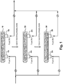
- FIG. 1 an exemplary embodiment of a filtration scheme is illustrated.
- a stream la of an aqueous liquid is provided, wherein the aqueous liquid has been treated with a biocide.
- the stream 1a is filtered with a filtration surface 10, creating a second stream 1b.
- the stream 1a of the aqueous liquid is diverted (stream 1a becomes stream 2a) to a filtration surface 20 that has a lower porosity than the filtration surface 10, which is filtered thereby creating a third stream 2b.
- the stream 2a of the aqueous liquid may be diverted (stream 2a becoming stream 3a) to a filtration surface 30, which is filtered thereby creating a fourth stream 3b. At least a portion of any filtrate stream (streams 1b, 2b and 3b) is returned to the industrial process.
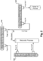
- FIG. 2 another exemplary embodiment (not according to the invention) of a filtration scheme is illustrated.
- a stream of an aqueous liquid (Fluid IN) is filtered with a filtration surface 110 having a given porosity.
- the filtrate (Fluid OUT) may be filtered full-flow with a filtration surface 120 that is less porous than the filtration surface 110.
- the filtrate may be returned to the industrial process, and a side stream (an example of a filtration loop stream) may be filtered with filtration surface 130, wherein filtration surface 130 is less porous than filtration surface 110.
- FIG. 3 illustrates a filter element 200 having at least two filtration surfaces.
- the illustrated embodiment has three filtration surfaces 210, 220, and 230, each progressively less porous than the previous filtration surface in a downstream direction.
- FIG. 4 illustrates a filter element 200 having at least two sequential filtration surfaces 210 and 220.
- the aqueous liquid enters (Fluid IN) the filter element 200 and is filtered by the first filtration surface 210 having a given porosity.
- the aqueous liquid then passes through the second filtration surface 220 and is returned to service in the aqueous cooling system (Fluid OUT).
- an optional self-cleaning apparatus is built into the filter element 200, the self-cleaning apparatus able to vacuum the second filtration surface 220.
- the pressure drop across the second filtration surface 220 and/or the filter element 200 increases. Once the pressure drop reaches a setpoint, a vacuum cycle is triggered.
- a rinse valve 270 opens to an atmospheric drain (Drain) causing a drop in pressure within the filter element 200.
- the drop in pressure within the filter element 200 creates a backflush stream, thereby pulling the contamination from the second filtration surface 220.
- the aqueous liquid and contamination are sucked into the conduit 250 via the several nozzles 260.
- the aqueous liquid and contamination exit the conduit 250 via either of two tubes 240 through the rinse valve 270 and out the drain.
- the cleaning apparatus that includes the two tubes 240, the conduit 250, and the several nozzles 260 can be driven by a motor 300.
- one, two or more, including combinations of various devices, of the following devices may be included within the industrial process: a pressure monitoring device, a flow monitoring device, and a turbidity monitoring device, each operably attached to the industrial process so as to provide input related to the biocide demand of the aqueous liquid within the industrial process.
- a microbial monitoring device may be operably attached to the industrial process and provide further input related to the biocide demand of the aqueous liquid within the industrial process.
- a biocide generating device may be operably attached to the industrial system and controlled depending on the measured biocide demand of the aqueous liquid within the industrial process.
- biocide generating devices include ozone generators, ultraviolet radiation generators, and chlorine generators.
- the disclosure is directed toward a method for inhibiting microbial fouling in an aqueous liquid having a biocide demand, which in certain embodiments takes the form of improving efficiency in biocide dosing of the aqueous liquid.
- the aqueous liquid is present in an industrial process, which in certain embodiments takes the form of an aqueous cooling system.
- the aqueous cooling system is a recirculation-type aqueous cooling system.
- the aqueous cooling system is a single-pass-type aqueous cooling system.
- the aqueous liquid having a biocide demand is treated with a biocide.
- the treatment takes the form of dosing the biocide at a dosage rate.
- dosing is a species of "treating.” Dosing refers to the continuous, semi-continuous, or intermittent combining of a biocide and an aqueous liquid that has a biocide demand.
- Treatment refers to combining of a biocide and an aqueous liquid that has a biocide demand, even if the combining does not happen in a continuous fashion or on a regular basis.
- treatment occurs by introducing a biocide in solid, liquid, or gas form into an aqueous liquid.
- treatment occurs by physically introducing a biocide into an aqueous liquid (e.g., ultraviolet radiation).
- treatment occurs by generating a biocide in situ (e.g., ozone) from one or more precursors within an aqueous liquid.
- a biocide in situ e.g., ozone
- the biocide may be one or a combination of more than one chemical substances that are known to effectively kill microbiological organisms or at least inhibit microbiological function (e.g., growth and/or reproduction) when present in a second substance at a known concentration.
- biocides include oxidizing biocides, non-oxidizing biocides, or physical biocides.
- Physical biocides may include, for example, steam sterilization or ultraviolet radiation.
- Oxidizing biocides include, but are not limited to, stabilized oxidants and halogenated oxidants, which may include chlorine bleach; chlorine; bromine; iodine; materials capable of releasing chlorine, bromine, and/or iodine; inorganic peroxides; organic peroxides; chlorine dioxide; ethylene oxide; ozone; chloramines compounds; precursors thereof, and combinations thereof.
- Non-oxidizing biocides include, but are not limited to, quaternary ammonium compounds; glutaraldehyde; isothiazolin; 2,2-dibromo-3-nitrilopropionamide; 2-bromo-2-nitropropane-1,3-diol; 1-bromo-1-(bromomethyl)-1,3-propanedicarbonitrile; tetrachloroisophthalonitrile; alkyldimethylbenzylammonium chloride; dimethyl dialkyl ammonium chloride; didecyl dimethyl ammonium chloride; poly(oxyethylene(dimethyliminio)ethylene(dimethyliminio)ethylene dichloride; methylene bisthiocyanate; 2-decylthioethanamine; tetrakishydroxymethyl phosphonium sulfate; dithiocarbamate; cyanodithioimidocarbonate; 2-methyl-5-nitroimidazole-1-ethanol; 2-(2-
- Biocide demand of the aqueous liquid can be monitored using one or more of various operating techniques, including but not limited to backwash count, vacuum count, pressure drop across at least one filtration surface, and measurement of oxidation-reduction potential of at least a portion of the aqueous liquid.
- One typical technique involves measuring the oxidation-reduction potential ("ORP") of an aqueous liquid or aqueous liquid stream.
- ORP oxidation-reduction potential
- a decrease in ORP can indicate an increase in microbial activity or a decrease in biocide concentration. In other words, a decreasing ORP typically indicates an increasing biocide demand.
- a typical ORP-measuring device is an electrochemical measuring device that utilizes a probe.
- ORP-measuring devices are available from any of several vendors including, but not limited to, Hach Company, Loveland, Colorado, and Rosemount Measurement, Chanhassen, Minnesota. According to the invention ORP is monitored to determine the biocide demand.
- biocide demand of the aqueous liquid can be measured by counting filtration surface cleaning cycles.
- a cleaning cycle count (usually an average number of cycles per unit of time) can be correlated to the biocide demand or a change of the biocide demand of the aqueous liquid.
- cleaning cycles include backwash and vacuum (for appropriately equipped filtration surfaces).
- a backwash count per period of time, or change or lack thereof is correlated to the biocide demand of the aqueous liquid.
- a typical backwash cycle isolates the filtration surface(s) to be backwashed from use, flows a non-contaminated liquid (usually purified water) in a counter-flow direction through the filtration surface(s), and sends the counter-flowed liquid to a waste stream. Once backwashed, the filtration surface(s) can be returned to service.
- the need for backwash is triggered on an as-needed basis (i.e., not scheduled in advance at set time periods) based on one or more of increased pressure drop across the filtration surface, decreased fluid flux across the filtration surface, or otherwise decreased performance of the filtration surface.
- a high backwash count can indicate an increased biocide demand for aqueous liquids that are known to have microbial activity.
- FIG. 5 illustrated in more detail below, illustrates the phenomenon.
- a change in porosity of the utilized filtration surface i.e., switching filtration surfaces
- one or more of the filtration surfaces that are utilized include self-cleaning apparatuses comprising a vacuum system that removes at least a portion of the debris that has collected on a particular filtration surface.
- self-cleaning apparatuses comprising a vacuum system that removes at least a portion of the debris that has collected on a particular filtration surface.
- vacuum count per period of time, or a change or lack thereof can be correlated to the biocide demand of the aqueous liquid.
- pressure drop, or a change in pressure drop or lack thereof over time, across one or more filtration surfaces can be correlated to the biocide demand of the aqueous liquid.
- reaching a steady state with respect to pressure drop across a filtration surface indicates that the stream being filtered should be diverted to a less porous filtration surface.
- At least a portion of an aqueous liquid is diverted to a filtration surface or into a filtration loop, thereby producing a stream.
- diverting means "causing to move to an identified location.” Such diversion can be performed using known techniques such as via piping and/or pumping.
- the portion of the aqueous liquid may be diverted from a container into a conduit ( e.g., pipe), from one conduit to another conduit, from a water source to a conduit, or any other suitable arrangement depending on the circumstances.
- filtration may be performed via one or more techniques selected from the group consisting of dead end filtration, flow-through filtration, cross-flow filtration, and combinations thereof. Persons having skill in the art of filtration will readily recognize these potential arrangements and the advantages and disadvantages of each.
- a stream of an aqueous liquid is initially filtered with a first filtration surface until a steady state is reached.
- An exemplary technique (not according to the invention) to determine steady state for this filtration is by monitoring pressure drop across the first filtration surface. Once the monitored pressure drop is reasonably constant for a constant flow rate, the stream of the aqueous liquid is diverted to a second filtration surface that has a lower porosity than the first filtration surface.
- a set of at least two sequential filtration surfaces are utilized to filter a stream of an aqueous liquid that has a biocide demand.
- the set includes at least two filtration surfaces that become less porous in a downstream direction.
- the set is present in a single filter element.
- the set includes three filter elements that are progressively less porous in a downstream direction.
- FIG. 5 illustrates the average number of backwashes per day for an 18-week span for a particular aqueous cooling system.
- the filter on this particular aqueous cooling system was installed with a 100 micron screen.
- the number of backwashes indicates the number of times the filter performs the process of cleaning itself following entrapment of solids by the filter.
- FIG. 5 after a period of operation the backwash counts steadied to an average of 4.25 backwashes per day.
- the filter was taken off-line for a short period around week 13 (hence 0 backwashes) and then recommissioned with a smaller porosity (50 micron) screen.
- the backwash counts thereafter increased to an average of 6.6 per day suggesting that the filter was trapping more debris and hence improving the water quality more than when it had attained a steady state.
- FIG. 6 illustrates an aqueous cooling system that was running without an installed filtration system (Test 1).
- Biocide was dosed as a slug dose into the aqueous liquid, i.e., the biocide was introduced within a short period of time.
- ORP oxidation reduction potential
- the observed ORP increase gradually declined over time, as the applied biocide was consumed. Consumption of the biocide occured due to biocide demand, e.g., the presence of inorganic or organic matter in the aqueous liquid, and physical loss due to volatilization.
Landscapes
- Chemical & Material Sciences (AREA)
- Life Sciences & Earth Sciences (AREA)
- Hydrology & Water Resources (AREA)
- Engineering & Computer Science (AREA)
- Environmental & Geological Engineering (AREA)
- Water Supply & Treatment (AREA)
- Organic Chemistry (AREA)
- Chemical Kinetics & Catalysis (AREA)
- Separation Using Semi-Permeable Membranes (AREA)
- Treatment Of Water By Oxidation Or Reduction (AREA)
- Agricultural Chemicals And Associated Chemicals (AREA)
Description
- The disclosure is directed to methods of inhibiting fouling in liquid systems by using biocides and filtration techniques.
- Throughout the world, there are many different types of industrial water systems. Industrial water systems exist at least in part so that necessary chemical, mechanical, and biological processes can be conducted to reach their desired outcomes. Even the best water treatment programs currently available cannot always prevent fouling in industrial water systems. If an industrial water system is not periodically cleaned to remove contaminants, the industrial water system will almost certainly become heavily fouled.
- Fouling has a negative impact on the industrial water system. For example, severe mineral scale (i.e., inorganic material) can build on the water contact surfaces. Scale on an industrial water system surface presents an ideal environment for the growth of microorganisms. The presence of microorganisms poses an additional challenge to water treatment of the industrial water system, as biocides, scale inhibitors, and/or corrosion inhibitors may be necessary to maintain efficient operation of the industrial water system.
- Evaporative cooling water systems are particularly prone to fouling, which can occur via a variety of mechanisms. Non-limiting examples of fouling mechanisms include deposition of airborne, water-borne, water-formed, and/or microbiological contaminants; water stagnation; process leaks; and other factors. If fouling is allowed to progress, the industrial water system can suffer from decreased operational efficiency, equipment failure, lack of water quality control, and increased health-related risks associated with microbial fouling.
- As previously mentioned, microbiological contaminants may cause fouling. Non-limiting sources of microbiological (i.e., microbial) contamination are airborne contamination, makeup water, process leaks, and improperly cleaned process equipment. These microbials can establish colonies on any wettable or even semi-wettable surface of the industrial water system. Once microbial counts are present in the bulk water, within a short period of time, more than 99% of the microbes present in the water will be present on all surfaces within biofilms.
- By design, cooling towers are excellent air scrubbers. As a consequence of the cooling process, a cooling tower typically flushes airborne contaminants into the water phase. These contaminants can ultimately find their way to the heat exchanger surfaces, where they become deposited, thereby reducing heat transfer. Non-limiting examples of such contaminants include particulate matter, organic and inorganic contaminants, oils, process contaminants, microorganisms, and so forth. Suspended matter in the cooling water provides the microorganisms with readily available nourishment for sustaining life and reproduction. It is well established that the presence of inorganic, organic, and microbiological deposits have a detrimental impact on the operational parameters of an industrial cooling system, resulting in reduced efficiency and increased operating cost.
- A filtration system can be used to at least partially remove particulate contaminants and prevent them from reaching concentrations that can adversely impact efficient cooling system operation. The filtration system may be a full-flow in line system or a partial flow side stream system. The side stream configuration provides particular advantages to the full flow system, such as allowing for a smaller filtration unit and the ability to service off-line while not affecting the cooling process. Generally, the side stream configuration only draws between 2 and 10 percent of the flow as compared to the overall circulation of the cooling system.
- Any or a combination of several different types of filters may be utilized for the purpose of filtration, and their use depends on the nature of the water and the level of purification wishing to be attained. Non-limiting examples include sand filters, cartridge filters, screen filters, and membrane filters, which may employ ultrafiltration, microfiltration, reverse osmosis, and forward osmosis. Typically in a filtration system, the water to be cleaned wets and passes through the entire filtration surface, with cleaner water leaving the filtration system as filtrate. When sufficient dirt has collected on the filtration surface, the filtration surface should be cleaned, thereby restoring performance. Methods of cleaning the filtration surface depend on the design of the filtration device. For example, a cartridge filter is not typically cleaned but instead replaced. However, a sand or screen filter will typically undergo a manual or automated backwash cycle to remove the collected contaminants. For membrane filters, there may be similar chemical or non-chemical based cleaning processes, depending on their design.
-
US2013015137 A1 discloses a method of inhibiting microbial fouling in aqueous cooling systems with controlled dosage of biocide and a filtration system. - The present invention is directed to a method of inhibiting microbial fouling according to
claim 1. Preferred embodiments of the invention are according todependent claims 2 to 10. - In a first exemplary embodiment (not according to the invention), the disclosure is directed to a method of inhibiting microbial fouling. The method comprises providing an industrial process that contains an aqueous liquid having a biocide demand and a first filtration surface having a given porosity and operating variables selected from the group consisting of backwash count, vacuum count, pressure drop across the first filtration surface, oxidation-reduction potential, and combinations thereof. The aqueous liquid is treated with a biocide. The biocide demand of the biocide-treated aqueous liquid is determined by monitoring at least one of the operating variables of the first filtration surface. A stream of the biocide-treated aqueous liquid is provided and filtered with the first filtration surface to produce a second stream that is initially returned to the industrial process. The filtering and returning are continued until a steady state with respect to the first filtration surface is reached. Reaching steady state with respect to the first filtration surface is then identified, whereupon the stream of the biocide-treated aqueous liquid is diverted away from the first filtration surface to a second filtration surface having a lower porosity than the first filtration surface. The diverted stream is then filtered with the second filtration surface to produce a third stream, and at least a portion of the third stream is returned to the industrial process.
- In a second exemplary embodiment (not according to the invention), the disclosure is directed to a method of inhibiting microbial fouling. The method comprises providing an aqueous cooling system that contains an aqueous liquid having a biocide demand. The aqueous liquid is treated with a biocide. At least a portion of the biocide-treated aqueous liquid is diverted to a first filtration surface having a given porosity, thereby producing a first stream. The first stream is filtered with the first filtration surface, thereby producing a second stream. At least a portion of the second stream is filtered with a second filtration surface that is less porous than the first filtration surface, thereby producing a third stream. The biocide demand of the biocide-treated aqueous liquid is determined by monitoring at least one operating variable for the second filtration surface, the at least one operating variable selected from the group consisting of backwash count, vacuum count, pressure drop across the second filtration surface, oxidation-reduction potential, and combinations thereof. At least a portion of the streams is returned to the aqueous cooling system.
- In a third exemplary embodiment (not according to the invention), the disclosure is directed to an automated method of improving efficiency in biocide dosing into a recirculation-type aqueous cooling system. The method comprises providing a recirculation-type aqueous cooling system that contains an aqueous liquid having a biocide demand. A biocide is dosed into the aqueous liquid at a dosage rate. At least a portion of the biocide-dosed aqueous liquid is diverted into a filtration loop thereby creating a filtration loop stream having a filtration loop flow rate within the aqueous cooling system. The filtration loop stream is sequentially filtered with at least one set of at least two filtration surfaces thereby creating a filtrate. The at least two filtration surfaces are progressively less porous in a downstream direction. Each of the at least one set of at least two filtration surfaces has operating variables selected from the group consisting of backwash count, vacuum count, pressure drop across each set of at least two filtration surfaces, oxidation-reduction potential, and combinations thereof. The biocide demand of the biocide-treated aqueous liquid is determined either intermittently or continuously by monitoring at least one of the operating variables of the at least one set of at least two filtration surfaces. A process parameter based on the determined biocide demand is adjusted. The process parameter is selected from the group consisting of the dosage rate of the biocide, the filtration loop flow rate, a quantity of the at least one set of at least two filtration surfaces, and combinations thereof.
- The advantages of the present disclosure will become more readily apparent to those of ordinary skill in the relevant art after reviewing the following detailed description and accompanying drawings, wherein:
-
FIG. 1 illustrates an exemplary embodiment of a filtration scheme of the disclosed methods; -
FIG. 2 illustrates an exemplary embodiment of a filtration scheme of the disclosed methods; -
FIG. 3 illustrates an exemplary embodiment of a filtration scheme and a set of filtration surfaces within a filter element of the disclosed methods; -
FIG. 4 illustrates an exemplary embodiment of a filtration scheme and a set of filtration surfaces within a filter element of the disclosed methods; -
FIG. 5 graphically illustrates data achieved when practicing an embodiment of a disclosed method; -
FIG. 6 graphically illustrates data achieved when practicing an embodiment of a disclosed method. - The disclosure is generally directed to filtration techniques useful for reducing or eliminating microbial fouling and/or improving efficiency of biocide dosing into aqueous industrial liquids. Application of one or more of the disclosed filtration techniques may be particularly useful for aqueous cooling systems.
- As it pertains to this disclosure, "fouling" and "contamination" refer to the presence or the deposition of any extraneous or undesirable organic or inorganic material in a water-containing industrial process or onto one or more surfaces within the water-containing industrial process. "Microbial fouling" refers to the presence or deposition of any extraneous or undesirable microbiological organism in a water-containing industrial process.
- As it pertains to this disclosure, "aqueous cooling system" refers to a system that uses a water-containing liquid (i.e., aqueous liquid) to cool at least a portion of an industrial process or an enclosed space. A typical aqueous cooling system may utilize any one or combination of a chiller, a cooling tower, and an air washer, to transfer heat energy from the water to another substance.
- As it pertains to this disclosure, "stream" refers to a flowing liquid. A non-limiting example of a stream is an aqueous liquid flowing through a pipe.
- As it pertains to this disclosure, "steady state" generally refers to a situation in which all state variables are statistically constant (e.g., within a 90% confidence interval of a setpoint or desired value) in spite of ongoing factors that strive to change the variables. For the present disclosure, state variables are generally related to filtration (e.g., number of filtration surfaces, pressure drop across at least one filtration surface, flow rate/flux across at least one filtration surface, number of backwash or vacuum cycles per a period of time, etc.), oxidation-reduction potential, and biocide dosage. For example, a particular filtration reaches steady state when a stream having a reasonably constant flow rate reaches a reasonably constant pressure drop across the filtration surface(s). In certain embodiments, steady state can be determined when a process has reached statistical process control around one or more setpoints or one or more target values for a certain period of time.
- As it pertains to this disclosure, "filtration surface" refers to a section of filtration material where filtration takes place. A filtration surface may or may not be housed in a filter element. A filter element (see below) may have one or more filtration surfaces within each element. A filtration surface need not be flat.
- As it pertains to this disclosure, "filter element" refers to an interchangeable unit that comprises at least one filtration surface. In certain embodiments of the methods of the present disclosure, each filter element comprises a set of at least two filtration surfaces, wherein the at least two filtration surfaces are progressively less porous in a downstream direction. For purposes of this disclosure, "cartridge" is a species of the generic "element."
- As it pertains to this disclosure, "biocide" refers to a substance that is used to kill microbiological organisms or at least inhibit microbiological function (e.g., growth and/or reproduction) that may be present in a second substance.
- As it pertains to this disclosure, "biocide demand" refers to the amount of biocide needed to inhibit microbial fouling, which can be monitored based on one or more of several variables described herein.
- As it pertains to this disclosure, "automatic," "automatically," "automated," and other similar terms refer to a method or portion thereof that is performed without human intervention or substantially without human intervention. For example, a process carried out automatically (i.e., an "automated process") would measure a variable and take action (e.g., change a pump speed, open or close a valve, increase heating or cooling, etc.) based on a comparison of the measured variable to a standard value (i.e., a setpoint or a steady state calculation) without a person having to do anything to make the action take place, outside of initially providing all necessary equipment, plumbing, wiring, power, programming, ingredients, and so forth.
- The invention is directed to a method of inhibiting microbial fouling. The method comprises providing an industrial process, namely an aqueous cooling system, that contains an aqueous liquid having a biocide demand and a first filtration surface having a given porosity and an operating variable being the oxidation reduction potential. The aqueous liquid is treated with a biocide. The biocide demand of the biocide-treated aqueous liquid is determined by monitoring said operating variable. A stream of the biocide-treated aqueous liquid is provided and filtered with the first filtration surface to produce a second stream that is initially returned to the aqueous cooling system. The filtering and returning are continued until a steady state with respect to the first filtration surface is reached. Steady state refers to a situation in which all state variables are statistically constant within a 90% confidence interval of a setpoint or desired value in spite of ongoing factors that strive to change the variables. Reaching steady state with respect to the first filtration surface is then identified, whereupon the stream of the biocide-treated aqueous liquid is diverted away from the first filtration surface to a second filtration surface having a lower porosity than the first filtration surface. The diverted stream is then filtered with the second filtration surface to produce a third stream, and at least a portion of the third stream is returned to the aqueous cooling system. The state variables are the number of backwash cycles per period of time, oxidation-reduction potential, and biocide dosage.
- In a second exemplary embodiment (not according to the invention), the disclosure is directed to a method of inhibiting microbial fouling. The method comprises providing an aqueous cooling system that contains an aqueous liquid having a biocide demand. The aqueous liquid is treated with a biocide. At least a portion of the biocide-treated aqueous liquid is diverted to a first filtration surface having a given porosity, thereby producing a first stream. The first stream is filtered with the first filtration surface, thereby producing a second stream. At least a portion of the second stream is filtered with a second filtration surface that is less porous than the first filtration surface, thereby producing a third stream. The biocide demand of the biocide-treated aqueous liquid is determined by monitoring at least one operating variable for the second filtration surface, the at least one operating variable selected from the group consisting of backwash count, vacuum count, pressure drop across the second filtration surface, oxidation-reduction potential, and combinations thereof. At least a portion of the streams is returned to the aqueous cooling system.
- In a third exemplary embodiment (not according to the invention), the disclosure is directed to an automated method of improving efficiency in biocide dosing into a recirculation-type aqueous cooling system. The method comprises providing a recirculation-type aqueous cooling system that contains an aqueous liquid having a biocide demand. A biocide is dosed into the aqueous liquid at a dosage rate. At least a portion of the biocide-dosed aqueous liquid is diverted into a filtration loop thereby creating a filtration loop stream having a filtration loop flow rate within the aqueous cooling system. The filtration loop stream is sequentially filtered with at least one set of at least two filtration surfaces thereby creating a filtrate. The at least two filtration surfaces are progressively less porous in a downstream direction. Each of the at least one set of at least two filtration surfaces has operating variables selected from the group consisting of backwash count, vacuum count, pressure drop across each set of at least two filtration surfaces, oxidation-reduction potential, and combinations thereof. The biocide demand of the biocide-treated aqueous liquid is determined either intermittently or continuously by monitoring at least one of the operating variables of the at least one set of at least two filtration surfaces. A process parameter based on the determined biocide demand is adjusted. The process parameter is selected from the group consisting of the dosage rate of the biocide, the filtration loop flow rate, a quantity of the at least one set of at least two filtration surfaces, and combinations thereof.
- Referring to
FIG. 1 , an exemplary embodiment of a filtration scheme is illustrated. For the exemplary embodiment illustrated inFIG. 1 , a stream la of an aqueous liquid is provided, wherein the aqueous liquid has been treated with a biocide. Thestream 1a is filtered with afiltration surface 10, creating asecond stream 1b. Once steady state filtration (with respect to filtration surface 10) is achieved, thestream 1a of the aqueous liquid is diverted (stream 1a becomesstream 2a) to afiltration surface 20 that has a lower porosity than thefiltration surface 10, which is filtered thereby creating athird stream 2b. Optionally, upon reaching steady state filtration (with respect to filtration surface 20), thestream 2a of the aqueous liquid may be diverted (stream 2a becoming stream 3a) to afiltration surface 30, which is filtered thereby creating afourth stream 3b. At least a portion of any filtrate stream (streams - Referring to
FIG. 2 , another exemplary embodiment (not according to the invention) of a filtration scheme is illustrated. For the exemplary embodiment illustrated inFIG. 2 , a stream of an aqueous liquid (Fluid IN) is filtered with afiltration surface 110 having a given porosity. The filtrate (Fluid OUT) may be filtered full-flow with afiltration surface 120 that is less porous than thefiltration surface 110. Alternately, the filtrate may be returned to the industrial process, and a side stream (an example of a filtration loop stream) may be filtered withfiltration surface 130, whereinfiltration surface 130 is less porous thanfiltration surface 110. - Referring to
FIG. 3, FIG. 3 illustrates afilter element 200 having at least two filtration surfaces. The illustrated embodiment has threefiltration surfaces - Referring to
FIG. 4, FIG. 4 illustrates afilter element 200 having at least twosequential filtration surfaces filter element 200 and is filtered by thefirst filtration surface 210 having a given porosity. The aqueous liquid then passes through thesecond filtration surface 220 and is returned to service in the aqueous cooling system (Fluid OUT). - For the embodiment illustrated in
FIG. 4 , an optional self-cleaning apparatus is built into thefilter element 200, the self-cleaning apparatus able to vacuum thesecond filtration surface 220. As contamination collects on thesecond filtration surface 220, the pressure drop across thesecond filtration surface 220 and/or thefilter element 200 increases. Once the pressure drop reaches a setpoint, a vacuum cycle is triggered. A rinsevalve 270 opens to an atmospheric drain (Drain) causing a drop in pressure within thefilter element 200. The drop in pressure within thefilter element 200 creates a backflush stream, thereby pulling the contamination from thesecond filtration surface 220. The aqueous liquid and contamination are sucked into theconduit 250 via theseveral nozzles 260. The aqueous liquid and contamination exit theconduit 250 via either of twotubes 240 through the rinsevalve 270 and out the drain. The cleaning apparatus that includes the twotubes 240, theconduit 250, and theseveral nozzles 260 can be driven by amotor 300. - Optionally, one, two or more, including combinations of various devices, of the following devices may be included within the industrial process: a pressure monitoring device, a flow monitoring device, and a turbidity monitoring device, each operably attached to the industrial process so as to provide input related to the biocide demand of the aqueous liquid within the industrial process. Optionally, a microbial monitoring device may be operably attached to the industrial process and provide further input related to the biocide demand of the aqueous liquid within the industrial process. Optionally, a biocide generating device may be operably attached to the industrial system and controlled depending on the measured biocide demand of the aqueous liquid within the industrial process. Non-limiting examples of biocide generating devices include ozone generators, ultraviolet radiation generators, and chlorine generators.
- In certain embodiments according to the invention and the second, and third embodiments (not according to the invention) disclosed herein, the disclosure is directed toward a method for inhibiting microbial fouling in an aqueous liquid having a biocide demand, which in certain embodiments takes the form of improving efficiency in biocide dosing of the aqueous liquid. In certain embodiments according to the invention and the second, and third embodiments (not according to the invention) disclosed herein, the aqueous liquid is present in an industrial process, which in certain embodiments takes the form of an aqueous cooling system. In certain embodiments according to the invention and the second, and third embodiments (not according to the invention) disclosed herein, the aqueous cooling system is a recirculation-type aqueous cooling system. In other embodiments according to the invention and the second, and third embodiments (not according to the invention) disclosed herein, the aqueous cooling system is a single-pass-type aqueous cooling system.
- In certain embodiments according to the invention and the second, and third embodiments (not according to the invention) disclosed herein, the aqueous liquid having a biocide demand is treated with a biocide. In certain embodiments according to the invention and the second, and third embodiments (not according to the invention) disclosed herein, the treatment takes the form of dosing the biocide at a dosage rate. As it pertains to this disclosure, "dosing" is a species of "treating." Dosing refers to the continuous, semi-continuous, or intermittent combining of a biocide and an aqueous liquid that has a biocide demand. Treatment refers to combining of a biocide and an aqueous liquid that has a biocide demand, even if the combining does not happen in a continuous fashion or on a regular basis. In certain embodiments according to the invention and the second, and third embodiments (not according to the invention) disclosed herein, treatment occurs by introducing a biocide in solid, liquid, or gas form into an aqueous liquid. In certain embodiments according to the invention and the second, and third embodiments (not according to the invention) disclosed herein, treatment occurs by physically introducing a biocide into an aqueous liquid (e.g., ultraviolet radiation). In certain embodiments according to the invention and the second, and third embodiments (not according to the invention) disclosed herein, treatment occurs by generating a biocide in situ (e.g., ozone) from one or more precursors within an aqueous liquid.
- The biocide may be one or a combination of more than one chemical substances that are known to effectively kill microbiological organisms or at least inhibit microbiological function (e.g., growth and/or reproduction) when present in a second substance at a known concentration.
- Non-limiting examples of biocides include oxidizing biocides, non-oxidizing biocides, or physical biocides. Physical biocides may include, for example, steam sterilization or ultraviolet radiation. Oxidizing biocides include, but are not limited to, stabilized oxidants and halogenated oxidants, which may include chlorine bleach; chlorine; bromine; iodine; materials capable of releasing chlorine, bromine, and/or iodine; inorganic peroxides; organic peroxides; chlorine dioxide; ethylene oxide; ozone; chloramines compounds; precursors thereof, and combinations thereof. Non-oxidizing biocides include, but are not limited to, quaternary ammonium compounds; glutaraldehyde; isothiazolin; 2,2-dibromo-3-nitrilopropionamide; 2-bromo-2-nitropropane-1,3-diol; 1-bromo-1-(bromomethyl)-1,3-propanedicarbonitrile; tetrachloroisophthalonitrile; alkyldimethylbenzylammonium chloride; dimethyl dialkyl ammonium chloride; didecyl dimethyl ammonium chloride; poly(oxyethylene(dimethyliminio)ethylene(dimethyliminio)ethylene dichloride; methylene bisthiocyanate; 2-decylthioethanamine; tetrakishydroxymethyl phosphonium sulfate; dithiocarbamate; cyanodithioimidocarbonate; 2-methyl-5-nitroimidazole-1-ethanol; 2-(2-bromo-2-nitroethenyl)furan; beta-bromo-beta-nitrostyrene; beta-nitrostyrene; beta-nitrovinyl furan; 2-bromo-2-bromomethyl glutaronitrile, bis(trichloromethyl) sulfone; S-(2-hydroxypropyl)thiomethanesulfonate; tetrahydro-3,5-dimethyl-2H-1,3,5-hydrazine-2-thione; 2-(thiocyanomethylthio)benzothiazole; 2-bromo-4'-hydroxyacetophenone; 1,4-bis(bromoacetoxy)-2-butene; bis(tributyltin)oxide; 2-(tert-butylamino)-4-chloro-6-(ethylamino)-s-triazine; dodecylguanidine acetate; dodecylguanidine hydrochloride; coco alkyldimethylamine oxide; n-coco alkyltrimethylenediamine; tetra-alkyl phosphonium chloride; 7-oxabicyclo[2.2.1]heptane-2,3-dicarboxylic acid; 4,5-dichloro-2-n-octyl-4-isothiazoline-3-one; 5-chloro-2-methyl-4-isothiazolin-3-one; 2-methyl-4-isothiazolin-3-one; precursors thereof; and combinations thereof.
- Biocide demand of the aqueous liquid can be monitored using one or more of various operating techniques, including but not limited to backwash count, vacuum count, pressure drop across at least one filtration surface, and measurement of oxidation-reduction potential of at least a portion of the aqueous liquid. One typical technique involves measuring the oxidation-reduction potential ("ORP") of an aqueous liquid or aqueous liquid stream. A decrease in ORP can indicate an increase in microbial activity or a decrease in biocide concentration. In other words, a decreasing ORP typically indicates an increasing biocide demand. A typical ORP-measuring device is an electrochemical measuring device that utilizes a probe. Exemplary embodiments of ORP-measuring devices are available from any of several vendors including, but not limited to, Hach Company, Loveland, Colorado, and Rosemount Measurement, Chanhassen, Minnesota. According to the invention ORP is monitored to determine the biocide demand.
- Alternatively (not according to the invention) or in addition to the above-described operating variables, biocide demand of the aqueous liquid can be measured by counting filtration surface cleaning cycles. A cleaning cycle count (usually an average number of cycles per unit of time) can be correlated to the biocide demand or a change of the biocide demand of the aqueous liquid. Non-limiting examples of cleaning cycles include backwash and vacuum (for appropriately equipped filtration surfaces).
- In certain embodiments according to the invention and the second, and third embodiments (not according to the invention) disclosed herein, a backwash count per period of time, or change or lack thereof, is correlated to the biocide demand of the aqueous liquid. A typical backwash cycle isolates the filtration surface(s) to be backwashed from use, flows a non-contaminated liquid (usually purified water) in a counter-flow direction through the filtration surface(s), and sends the counter-flowed liquid to a waste stream. Once backwashed, the filtration surface(s) can be returned to service.
- For certain embodiments according to the invention and the second, and third embodiments (not according to the invention) disclosed herein, the need for backwash is triggered on an as-needed basis (i.e., not scheduled in advance at set time periods) based on one or more of increased pressure drop across the filtration surface, decreased fluid flux across the filtration surface, or otherwise decreased performance of the filtration surface. For certain embodiments according to the invention and the second, and third embodiments (not according to the invention) disclosed herein, a high backwash count can indicate an increased biocide demand for aqueous liquids that are known to have microbial activity.
FIG. 5 , described in more detail below, illustrates the phenomenon. A change in porosity of the utilized filtration surface (i.e., switching filtration surfaces) may affect the steady state (i.e., take the process out of steady state) and affect the biocide demand and the parameters that may indicate the biocide demand. - In certain embodiments according to the invention and the second, and third embodiments (not according to the invention) disclosed herein, one or more of the filtration surfaces that are utilized include self-cleaning apparatuses comprising a vacuum system that removes at least a portion of the debris that has collected on a particular filtration surface. For embodiments that utilize a vacuum system, vacuum count per period of time, or a change or lack thereof, can be correlated to the biocide demand of the aqueous liquid.
- In certain embodiments according to the second, and third embodiments (not according to the invention) disclosed herein, pressure drop, or a change in pressure drop or lack thereof over time, across one or more filtration surfaces can be correlated to the biocide demand of the aqueous liquid. In certain embodiments of the present disclosure, reaching a steady state with respect to pressure drop across a filtration surface indicates that the stream being filtered should be diverted to a less porous filtration surface.
- In certain embodiments according to the invention and the second, and third embodiments (not according to the invention) disclosed herein, at least a portion of an aqueous liquid is diverted to a filtration surface or into a filtration loop, thereby producing a stream. As it pertains to the present application, "diverting" means "causing to move to an identified location." Such diversion can be performed using known techniques such as via piping and/or pumping. In certain embodiments, the portion of the aqueous liquid may be diverted from a container into a conduit (e.g., pipe), from one conduit to another conduit, from a water source to a conduit, or any other suitable arrangement depending on the circumstances.
- In certain embodiments according to the invention and the second, and third embodiments (not according to the invention) disclosed herein, filtration may be performed via one or more techniques selected from the group consisting of dead end filtration, flow-through filtration, cross-flow filtration, and combinations thereof. Persons having skill in the art of filtration will readily recognize these potential arrangements and the advantages and disadvantages of each.
- In certain embodiments according to the invention and the second, and third embodiments (not according to the invention) disclosed herein, a stream of an aqueous liquid is initially filtered with a first filtration surface until a steady state is reached. An exemplary technique (not according to the invention) to determine steady state for this filtration is by monitoring pressure drop across the first filtration surface. Once the monitored pressure drop is reasonably constant for a constant flow rate, the stream of the aqueous liquid is diverted to a second filtration surface that has a lower porosity than the first filtration surface.
- In certain embodiments according to the invention and the second, and third embodiments (not according to the invention) disclosed herein, a set of at least two sequential filtration surfaces are utilized to filter a stream of an aqueous liquid that has a biocide demand. In certain embodiments according to the invention and the second, and third embodiments (not according to the invention) disclosed herein, the set includes at least two filtration surfaces that become less porous in a downstream direction. In certain embodiments according to the invention and the second, and third embodiments (not according to the invention) disclosed herein, the set is present in a single filter element. In certain embodiments, the set includes three filter elements that are progressively less porous in a downstream direction.
- Referring to
FIG. 5, FIG. 5 illustrates the average number of backwashes per day for an 18-week span for a particular aqueous cooling system. The filter on this particular aqueous cooling system was installed with a 100 micron screen. The number of backwashes indicates the number of times the filter performs the process of cleaning itself following entrapment of solids by the filter. As shown inFIG. 5 , after a period of operation the backwash counts steadied to an average of 4.25 backwashes per day. The filter was taken off-line for a short period around week 13 (hence 0 backwashes) and then recommissioned with a smaller porosity (50 micron) screen. The backwash counts thereafter increased to an average of 6.6 per day suggesting that the filter was trapping more debris and hence improving the water quality more than when it had attained a steady state. - Referring to
FIG. 6, FIG. 6 illustrates an aqueous cooling system that was running without an installed filtration system (Test 1). Biocide was dosed as a slug dose into the aqueous liquid, i.e., the biocide was introduced within a short period of time. As a consequence of the biocide dosage, an increase in the oxidation reduction potential ("ORP") of the aqueous liquid was observed. The observed ORP increase gradually declined over time, as the applied biocide was consumed. Consumption of the biocide occured due to biocide demand, e.g., the presence of inorganic or organic matter in the aqueous liquid, and physical loss due to volatilization. - Subsequent to Test 1, a filter was installed on this system and
Test 2 was conducted. After a period of operation of the filter, which had two filtration surfaces (a coarse screen followed by a 100 micron screen) within the filter element, a similar increase in ORP as seen inTest 1 was observed forTest 2. However, the increase in ORP was significantly higher (approximately 30%) forTest 2 than forTest 1, even with overlapping biocide pump run times forTest 1 andTest 2. A more gradual decline in ORP was also observed forTest 2 as compared toTest 1. In other words, an amount of biocide dosage with filtration is significantly more effective in killing microbial growth than the same amount of biocide dosage without filtration. TheTest 2 results were unexpected following the use of a filter, as compared toTest 1. In other words, biocide treatment in combination with filtration, particularly dual-stage filtration, can aid with the inhibition of microbial fouling beyond utilizing merely biocide treatment. - To the extent that the terms "include," "includes," or "including" are used in the specification or the claims, they are intended to be inclusive in a manner similar to the term "comprising" as that term is interpreted when employed as a transitional word in a claim. Furthermore, to the extent that the term "or" is employed (e.g., A or B), it is intended to mean "A or B or both A and B." When the applicants intend to indicate "only A or B but not both," then the term "only A or B but not both" will be employed. Thus, use of the term "or" herein is the inclusive, and not the exclusive use. Also, to the extent that the terms "in" or "into" are used in the specification or the claims, it is intended to additionally mean "on" or "onto." Furthermore, to the extent that the term "connect" is used in the specification or the claims, it is intended to mean not only "directly connected to," but also "indirectly connected to" such as connected through another component or components. In the present disclosure, the words "a" or "an" are to be taken to include both the singular and the plural. Conversely, any reference to plural items shall, where appropriate, include the singular.
Claims (10)
- A method of inhibiting microbial fouling, the method comprising:providing an aqueous cooling system containing an aqueous liquid having a biocide demand and a first filtration surface (10) having a given porosity and an operating variable being the oxidation reduction potential;treating the aqueous liquid with a biocide;determining the biocide demand of the biocide-treated aqueous liquid by monitoring said operating variable;providing a stream (1a) of the biocide-treated aqueous liquid;filtering the stream (1a) of the biocide-treated aqueous liquid with the first filtration surface (10) to produce a second stream (1b) that is initially returned to the aqueous cooling system, and continuing the filtering and returning until a steady state with respect to the first filtration surface (10) is reached, wherein steady state refers to a situation in which all state variables are statistically constant within a 90% confidence interval of a setpoint or desired value in spite of ongoing factors that strive to change the variables;identifying that the steady state with respect to the first filtration surface (10) has been reached, whereupon the stream (1a) of the biocide-treated aqueous liquid is diverted away from the first filtration surface (10) to a second filtration surface (20) having a lower porosity than the first filtration surface (10);filtering the diverted stream (2a) with the second filtration surface (20) to produce a third stream (2b); andreturning at least a portion of the third stream (2b) to the aqueous cooling system;wherein the state variables are the number of backwash cycles per period of time, oxidation-reduction potential, and biocide dosage.
- The method of claim 1, wherein the stream (1a) of the aqueous liquid is either a full flow stream or a side stream.
- The method of claim 1, wherein the identifying that the steady state with respect to the first filtration surface (10) has been reached and the stream (2a) diversion from the first filtration surface (10) to the second filtration surface (20) is performed automatically.
- The method of any of claims 1-3, wherein the aqueous cooling system is a recirculation-type aqueous cooling system.
- The method of any of claims 1-4, wherein the biocide is an oxidizing biocide, non- oxidizing biocide, or physical biocide.
- The method of claim 5, wherein the oxidizing biocide is an selected from the group consisting of chlorine bleach; chlorine; bromine; iodine; materials capable of releasing chlorine, bromine, and/or iodine; inorganic peroxides; organic peroxides; chlorine dioxide; ethylene oxide; ozone; chloramines compounds; precursors thereof, and combinations thereof.
- The method of claim 5, wherein non-oxidizing biocide is selected from the group consisting of quaternary ammonium compounds; glutaraldehyde; isothiazolin; 2,2-dibromo-3-nitrilopropionamide; 2-bromo-2- nitropropane-l,3-diol; l-bromo-l-(bromomethyl)-l,3-propanedicarbonitrile; tetrachloroisophthalonitrile; alkyldimethylbenzylammonium chloride; dimethyl dialkyl ammonium chloride; didecyl dimethyl ammonium chloride; poly(oxyethylene(dimethyliminio)ethylene(dimethyliminio)ethylene dichloride; methylene bisthiocyanate; 2-decylthioethanamine; tetrakishydroxymethyl phosphonium sulfate; dithiocarbamate; cyanodithioimidocarbonate; 2-methyl-5-nitroimidazole-l-ethanol; 2-(2-bromo-2-nitroethenyl)furan; beta-bromo-beta-nitrostyrene; beta-nitrostyrene; beta-nitrovinyl furan; 2-bromo-2-bromomethyl glutaronitrile, bis(trichloromethyl) sulfone; S-(2-hydroxypropyl)thiomethanesulfonate; tetrahydro- 3,5-dimethyl-2H- 1 ,3,5-hydrazine-2-thione; 2-(thiocyanomethylthio)benzothiazole; 2- bromo-4'-hydroxyacetophenone; 1 ,4-bis(bromoacetoxy)-2-butene; bis(tributyltin)oxide; 2- (tert-butylamino)-4-chloro-6-(ethylamino)-s-triazine; dodecylguanidine acetate; dodecylguanidine hydrochloride; coco alkyldimethylamine oxide; n-coco alkyltrimethylenediamine; tetra-alkyl phosphonium chloride; 7-oxabicyclo[2.2.l]heptane-2,3-dicarboxylic acid; 4,5-dichloro-2-n-octyl-4-isothiazoline-3- one; 5-chloro-2-methyl-4-isothiazolin-3-one; 2-methyl-4-isothiazolin-3-one; precursors thereof; and combinations thereof.
- The method of claim 5, wherein the physical biocide is selected from the group consisting of steam sterilization or ultraviolet radiation.
- The method of any of claims 1-8, wherein one or more of the filtration surfaces (10, 20) that are utilized include self-cleaning apparatuses comprising a vacuum system that removes at least a portion of the debris that has collected on a particular filtration surface (10, 20).
- The method of any of claims 1-9, wherein the filtration is performed via one or more techniques selected from the group consisting of dead end filtration, flow-through filtration, cross-flow filtration, and combinations thereof.
Applications Claiming Priority (2)
| Application Number | Priority Date | Filing Date | Title |
|---|---|---|---|
| US13/835,720 US9505637B2 (en) | 2013-03-15 | 2013-03-15 | Methods of inhibiting fouling in liquid systems |
| PCT/US2014/016942 WO2014149308A1 (en) | 2013-03-15 | 2014-02-18 | Methods of inhibiting fouling in liquid systems |
Publications (3)
| Publication Number | Publication Date |
|---|---|
| EP2969972A1 EP2969972A1 (en) | 2016-01-20 |
| EP2969972A4 EP2969972A4 (en) | 2016-11-09 |
| EP2969972B1 true EP2969972B1 (en) | 2020-03-25 |
Family
ID=51522790
Family Applications (1)
| Application Number | Title | Priority Date | Filing Date |
|---|---|---|---|
| EP14768925.1A Active EP2969972B1 (en) | 2013-03-15 | 2014-02-18 | Methods of inhibiting fouling in liquid systems |
Country Status (5)
| Country | Link |
|---|---|
| US (2) | US9505637B2 (en) |
| EP (1) | EP2969972B1 (en) |
| CN (1) | CN105050964B (en) |
| CA (1) | CA2904571C (en) |
| WO (1) | WO2014149308A1 (en) |
Families Citing this family (5)
| Publication number | Priority date | Publication date | Assignee | Title |
|---|---|---|---|---|
| US9315396B2 (en) * | 2011-04-06 | 2016-04-19 | Water Conservation Technology International, Inc. | Water conservation methods combining osmotic membrane processed water for subsequent efficient use in cooling tower applications |
| US9505637B2 (en) | 2013-03-15 | 2016-11-29 | Ecolab Usa Inc. | Methods of inhibiting fouling in liquid systems |
| US10125038B2 (en) | 2016-02-19 | 2018-11-13 | King Fahd University Of Petroleum And Minerals | Treatment of water with UV/chlorine advanced oxidation |
| WO2017181005A1 (en) | 2016-04-15 | 2017-10-19 | Ecolab Usa Inc. | Performic acid biofilm prevention for industrial co2 scrubbers |
| GB201807987D0 (en) * | 2018-05-17 | 2018-07-04 | Univ Leeds Innovations Ltd | Reduction in microbial growth |
Citations (1)
| Publication number | Priority date | Publication date | Assignee | Title |
|---|---|---|---|---|
| US20130015137A1 (en) * | 2011-07-14 | 2013-01-17 | Ana-Mariana Urmenyi | Method of maintaining water quality in a process stream |
Family Cites Families (50)
| Publication number | Priority date | Publication date | Assignee | Title |
|---|---|---|---|---|
| DE3671843D1 (en) | 1985-04-10 | 1990-07-19 | Memtec Ltd | FILTER WITH VARIOUS VOLUME OR CONCENTRATOR. |
| US4719083A (en) | 1985-04-29 | 1988-01-12 | Chemed Corporation | Composition useful as corrosion inhibitor, anti-scalant and continuous biocide for water cooling towers and method of use |
| US4929365A (en) | 1989-09-18 | 1990-05-29 | Phillips Petroleum Co. | Biofilm control |
| DE3936798C1 (en) | 1989-11-04 | 1991-01-24 | Dortmunder Actien-Brauerei Ag, 4600 Dortmund, De | |
| US5244579A (en) * | 1992-10-09 | 1993-09-14 | Zenon Environmental Inc. | Transportable reverse osmosis water purification unit |
| US5492632A (en) | 1994-09-23 | 1996-02-20 | Motorola, Inc. | Method and system for monitoring and controlling a filtration process |
| FR2728896A1 (en) | 1994-12-29 | 1996-07-05 | Inst Francais Du Petrole | PROCESS FOR OBTAINING POLYGLYCEROLS AND POLYGLYCEROL ESTERS |
| BR9504673A (en) | 1995-09-15 | 1997-10-07 | Rhodia | Process for physical treatment of cooling waters using tangential filtration to improve their quality |
| US5576481A (en) | 1995-10-02 | 1996-11-19 | Ashland, Inc. | Method and apparatus for detecting microbiological fouling in aqueous systems |
| US6077435A (en) | 1996-03-15 | 2000-06-20 | Usf Filtration And Separations Group Inc. | Filtration monitoring and control system |
| US6036866A (en) * | 1997-03-10 | 2000-03-14 | Ecodyne Water Treatment, Inc. | Apparatus and method for fluid treatment units connected in parallel |
| US6398965B1 (en) | 1998-03-31 | 2002-06-04 | United States Filter Corporation | Water treatment system and process |
| US6045331A (en) | 1998-08-10 | 2000-04-04 | Gehm; William | Fluid pump speed controller |
| US6180056B1 (en) | 1998-12-10 | 2001-01-30 | Buckman Laboratories International Inc. | Method and compositions for minimizing biological and colloidal fouling |
| US6068012A (en) | 1998-12-29 | 2000-05-30 | Ashland, Inc. | Performance-based control system |
| BR0009799B1 (en) | 1999-04-30 | 2009-01-13 | control and continuous hemoinfiltration systems. | |
| IL131848A0 (en) * | 1999-09-09 | 2001-03-19 | Argad Eyal Ltd | Water treatment method and apparatus |
| KR100575113B1 (en) | 2000-06-21 | 2006-05-03 | 가부시키가이샤 구라레 | Porous hollow fiber membranes and method of making the same |
| US6379720B1 (en) | 2000-07-18 | 2002-04-30 | Nalco Chemical Company | Compositions containing hops extract and their use in water systems and process streams to control biological fouling |
| US6500345B2 (en) * | 2000-07-31 | 2002-12-31 | Maritime Solutions, Inc. | Apparatus and method for treating water |
| US6645383B1 (en) | 2000-08-25 | 2003-11-11 | Usf Consumer & Commercial Watergroup, Inc. | Process and apparatus for blending product liquid from different TFC membranes |
| US20030127391A1 (en) * | 2001-07-26 | 2003-07-10 | Craft Frank S. | Method for treatment of circulating cooling water |
| US7052614B2 (en) | 2001-08-06 | 2006-05-30 | A.Y. Laboratories Ltd. | Control of development of biofilms in industrial process water |
| GB2380474B (en) * | 2001-10-02 | 2003-09-10 | Hynes Patricia Rosemary | Water processing apparatus |
| US20090178587A9 (en) | 2001-10-09 | 2009-07-16 | Nalepa Christopher J | Control of biofilms in industrial water systems |
| US7572378B2 (en) | 2001-12-13 | 2009-08-11 | Turf Sentry, Inc. | Recycled irrigation water treatment system including reverse osmosis |
| US8668779B2 (en) * | 2002-04-30 | 2014-03-11 | Nalco Company | Method of simultaneously cleaning and disinfecting industrial water systems |
| US6699684B2 (en) * | 2002-07-23 | 2004-03-02 | Nalco Company | Method of monitoring biofouling in membrane separation systems |
| US6855257B2 (en) | 2002-09-17 | 2005-02-15 | The Boeing Company | Method and system for heat transfer |
| US7252096B2 (en) | 2003-04-08 | 2007-08-07 | Nalco Company | Methods of simultaneously cleaning and disinfecting industrial water systems |
| WO2004105589A2 (en) * | 2003-05-28 | 2004-12-09 | Hemocleanse Technologies, Llc | Sorbent reactor for extracorporeal blood treatment systems, peritoneal dialysis systems, and other body fluid treatment systems |
| US7632410B2 (en) * | 2003-08-21 | 2009-12-15 | Christopher Heiss | Universal water purification system |
| US7338595B2 (en) | 2003-11-13 | 2008-03-04 | Culligan International Company | Flow-through tank for water treatment |
| US7258786B2 (en) | 2004-04-13 | 2007-08-21 | Eastman Kodak Company | Container for inhibiting microbial growth in liquid nutrients |
| US20050242036A1 (en) * | 2004-04-29 | 2005-11-03 | Harris James J | Chemical and sludge free water treatment process |
| KR20060009127A (en) | 2004-07-20 | 2006-01-31 | 주식회사 삼양사 | Cooling Water Treatment Process Using Backwash Ultrafiltration and Nanofiltration |
| US7431840B2 (en) | 2005-08-24 | 2008-10-07 | Parkson Corporation | Denitrification process |
| WO2007075682A2 (en) | 2005-12-19 | 2007-07-05 | Hercules Incorporated | Biocide-enhanced mechanical treatment of water |
| US20070138092A1 (en) | 2005-12-20 | 2007-06-21 | Smith Paul J L | Method and system for controlling duration of a backwash cycle of a filtration system |
| WO2008086221A2 (en) | 2007-01-04 | 2008-07-17 | Advanced Biocatalytics Corporation | Enhanced oil recovery compositions comprising proteins and surfactants and methods of using the same |
| US20080245737A1 (en) | 2007-04-03 | 2008-10-09 | Siemens Water Technologies Corp. | Method and system for providing ultrapure water |
| SG10201610076SA (en) * | 2007-08-15 | 2017-01-27 | Evoqua Water Technologies Llc | Method and system for treating ballast water |
| US20090242484A1 (en) | 2008-04-01 | 2009-10-01 | Ana-Mariana Urmenyi | Environmentally friendly hybrid microbiological control technologies for cooling towers |
| US20100032375A1 (en) | 2008-08-05 | 2010-02-11 | Venkataraman Jagannathan | Reverse osmosis enhanced recovery hybrid process |
| US8216455B1 (en) * | 2008-12-01 | 2012-07-10 | O'brien Mackenzie Anne | Water handling system |
| KR101075885B1 (en) | 2009-04-28 | 2011-10-25 | (주)대우건설 | Water purification apparatus and method for using pressure filter and pore control fiber filter |
| US8486275B2 (en) | 2009-05-14 | 2013-07-16 | Omni Water Solutions, Inc. | Self-contained portable multi-mode water treatment system and methods |
| US9242880B2 (en) | 2010-12-28 | 2016-01-26 | Nalco Company | Strategy for on-site in situ generation of oxidizing compounds and application of the oxidizing compound for microbial control |
| JP2014161795A (en) * | 2013-02-25 | 2014-09-08 | Mitsubishi Heavy Ind Ltd | Water treatment system |
| US9505637B2 (en) | 2013-03-15 | 2016-11-29 | Ecolab Usa Inc. | Methods of inhibiting fouling in liquid systems |
-
2013
- 2013-03-15 US US13/835,720 patent/US9505637B2/en active Active
-
2014
- 2014-02-18 WO PCT/US2014/016942 patent/WO2014149308A1/en not_active Ceased
- 2014-02-18 CN CN201480015892.0A patent/CN105050964B/en active Active
- 2014-02-18 EP EP14768925.1A patent/EP2969972B1/en active Active
- 2014-02-18 CA CA2904571A patent/CA2904571C/en active Active
-
2016
- 2016-10-20 US US15/298,847 patent/US11186499B2/en active Active
Patent Citations (1)
| Publication number | Priority date | Publication date | Assignee | Title |
|---|---|---|---|---|
| US20130015137A1 (en) * | 2011-07-14 | 2013-01-17 | Ana-Mariana Urmenyi | Method of maintaining water quality in a process stream |
Also Published As
| Publication number | Publication date |
|---|---|
| US20170036928A1 (en) | 2017-02-09 |
| EP2969972A4 (en) | 2016-11-09 |
| WO2014149308A1 (en) | 2014-09-25 |
| US11186499B2 (en) | 2021-11-30 |
| EP2969972A1 (en) | 2016-01-20 |
| CA2904571A1 (en) | 2014-09-25 |
| US20140263086A1 (en) | 2014-09-18 |
| CA2904571C (en) | 2021-11-09 |
| CN105050964A (en) | 2015-11-11 |
| CN105050964B (en) | 2017-06-13 |
| US9505637B2 (en) | 2016-11-29 |
Similar Documents
| Publication | Publication Date | Title |
|---|---|---|
| US9409110B2 (en) | Method of maintaining water quality in a process stream | |
| US11186499B2 (en) | Methods of inhibiting fouling in liquid systems | |
| CA2788246C (en) | Membrane treatment of cooling tower blow down water | |
| Chew et al. | Practical performance analysis of an industrial-scale ultrafiltration membrane water treatment plant | |
| EP2276705B1 (en) | Environmentally friendly hybrid microbiological control technologies for cooling towers | |
| JP6305368B2 (en) | Water treatment method and apparatus | |
| US20090152178A1 (en) | Fully Automated Membrane Cleaning System and Methods of Use | |
| JP2018506269A (en) | Method and apparatus for treating food and / or containers containing food | |
| JP2015009174A (en) | Water treatment system and water treatment method for water treatment system | |
| JP6143159B2 (en) | Backwash type filtration device and method for removing deposits from filtration element | |
| US20120255918A1 (en) | Use of rhamnolipids in the water treatment industry | |
| RU153765U1 (en) | INSTALLATION FOR NON-REAGENT WATER TREATMENT | |
| JPH11179173A (en) | Operation method of membrane separator and membrane separator | |
| CN103304091A (en) | Ultrafiltration system | |
| KR102122007B1 (en) | Filterless water purification system | |
| US9034179B2 (en) | Method and device for the purification of an aqueous fluid | |
| Al-Shammari et al. | Comparative performance evaluation of microfiltration submerged and pressurized membrane treatment of wastewater | |
| US20240025780A1 (en) | Method for eliminating the use of chemical products in pre-treatment in seawater desalination plants based on reverse osmosis | |
| CN120903711A (en) | Circulating water treatment system | |
| JP2019202274A (en) | Membrane filtration apparatus, cleaning method of membrane filtration apparatus and water treatment method |
Legal Events
| Date | Code | Title | Description |
|---|---|---|---|
| PUAI | Public reference made under article 153(3) epc to a published international application that has entered the european phase |
Free format text: ORIGINAL CODE: 0009012 |
|
| 17P | Request for examination filed |
Effective date: 20151008 |
|
| AK | Designated contracting states |
Kind code of ref document: A1 Designated state(s): AL AT BE BG CH CY CZ DE DK EE ES FI FR GB GR HR HU IE IS IT LI LT LU LV MC MK MT NL NO PL PT RO RS SE SI SK SM TR |
|
| AX | Request for extension of the european patent |
Extension state: BA ME |
|
| DAX | Request for extension of the european patent (deleted) | ||
| A4 | Supplementary search report drawn up and despatched |
Effective date: 20161010 |
|
| RIC1 | Information provided on ipc code assigned before grant |
Ipc: C02F 1/50 20060101AFI20161004BHEP Ipc: B01D 29/62 20060101ALI20161004BHEP Ipc: C02F 1/32 20060101ALN20161004BHEP Ipc: B01D 37/04 20060101ALN20161004BHEP Ipc: C02F 1/72 20060101ALN20161004BHEP Ipc: C02F 103/02 20060101ALN20161004BHEP Ipc: C02F 1/76 20060101ALN20161004BHEP Ipc: C02F 1/78 20060101ALN20161004BHEP Ipc: B01D 29/11 20060101ALI20161004BHEP |
|
| RAP1 | Party data changed (applicant data changed or rights of an application transferred) |
Owner name: ECOLAB USA INC. |
|
| STAA | Information on the status of an ep patent application or granted ep patent |
Free format text: STATUS: EXAMINATION IS IN PROGRESS |
|
| 17Q | First examination report despatched |
Effective date: 20180306 |
|
| GRAP | Despatch of communication of intention to grant a patent |
Free format text: ORIGINAL CODE: EPIDOSNIGR1 |
|
| STAA | Information on the status of an ep patent application or granted ep patent |
Free format text: STATUS: GRANT OF PATENT IS INTENDED |
|
| RIC1 | Information provided on ipc code assigned before grant |
Ipc: B01D 29/62 20060101ALI20190925BHEP Ipc: C02F 1/76 20060101ALN20190925BHEP Ipc: C02F 1/00 20060101ALI20190925BHEP Ipc: C02F 1/78 20060101ALN20190925BHEP Ipc: B01D 29/11 20060101ALI20190925BHEP Ipc: B01D 37/04 20060101ALN20190925BHEP Ipc: C02F 1/72 20060101ALN20190925BHEP Ipc: C02F 103/02 20060101ALN20190925BHEP Ipc: C02F 1/32 20060101ALN20190925BHEP Ipc: C02F 1/50 20060101AFI20190925BHEP |
|
| INTG | Intention to grant announced |
Effective date: 20191011 |
|
| GRAS | Grant fee paid |
Free format text: ORIGINAL CODE: EPIDOSNIGR3 |
|
| GRAA | (expected) grant |
Free format text: ORIGINAL CODE: 0009210 |
|
| STAA | Information on the status of an ep patent application or granted ep patent |
Free format text: STATUS: THE PATENT HAS BEEN GRANTED |
|
| AK | Designated contracting states |
Kind code of ref document: B1 Designated state(s): AL AT BE BG CH CY CZ DE DK EE ES FI FR GB GR HR HU IE IS IT LI LT LU LV MC MK MT NL NO PL PT RO RS SE SI SK SM TR |
|
| REG | Reference to a national code |
Ref country code: GB Ref legal event code: FG4D |
|
| REG | Reference to a national code |
Ref country code: AT Ref legal event code: REF Ref document number: 1248363 Country of ref document: AT Kind code of ref document: T Effective date: 20200415 Ref country code: IE Ref legal event code: FG4D |
|
| REG | Reference to a national code |
Ref country code: DE Ref legal event code: R096 Ref document number: 602014062843 Country of ref document: DE |
|
| PG25 | Lapsed in a contracting state [announced via postgrant information from national office to epo] |
Ref country code: RS Free format text: LAPSE BECAUSE OF FAILURE TO SUBMIT A TRANSLATION OF THE DESCRIPTION OR TO PAY THE FEE WITHIN THE PRESCRIBED TIME-LIMIT Effective date: 20200325 Ref country code: FI Free format text: LAPSE BECAUSE OF FAILURE TO SUBMIT A TRANSLATION OF THE DESCRIPTION OR TO PAY THE FEE WITHIN THE PRESCRIBED TIME-LIMIT Effective date: 20200325 Ref country code: NO Free format text: LAPSE BECAUSE OF FAILURE TO SUBMIT A TRANSLATION OF THE DESCRIPTION OR TO PAY THE FEE WITHIN THE PRESCRIBED TIME-LIMIT Effective date: 20200625 |
|
| PG25 | Lapsed in a contracting state [announced via postgrant information from national office to epo] |
Ref country code: LV Free format text: LAPSE BECAUSE OF FAILURE TO SUBMIT A TRANSLATION OF THE DESCRIPTION OR TO PAY THE FEE WITHIN THE PRESCRIBED TIME-LIMIT Effective date: 20200325 Ref country code: SE Free format text: LAPSE BECAUSE OF FAILURE TO SUBMIT A TRANSLATION OF THE DESCRIPTION OR TO PAY THE FEE WITHIN THE PRESCRIBED TIME-LIMIT Effective date: 20200325 Ref country code: BG Free format text: LAPSE BECAUSE OF FAILURE TO SUBMIT A TRANSLATION OF THE DESCRIPTION OR TO PAY THE FEE WITHIN THE PRESCRIBED TIME-LIMIT Effective date: 20200625 Ref country code: HR Free format text: LAPSE BECAUSE OF FAILURE TO SUBMIT A TRANSLATION OF THE DESCRIPTION OR TO PAY THE FEE WITHIN THE PRESCRIBED TIME-LIMIT Effective date: 20200325 Ref country code: GR Free format text: LAPSE BECAUSE OF FAILURE TO SUBMIT A TRANSLATION OF THE DESCRIPTION OR TO PAY THE FEE WITHIN THE PRESCRIBED TIME-LIMIT Effective date: 20200626 |
|
| REG | Reference to a national code |
Ref country code: NL Ref legal event code: MP Effective date: 20200325 |
|
| REG | Reference to a national code |
Ref country code: LT Ref legal event code: MG4D |
|
| PG25 | Lapsed in a contracting state [announced via postgrant information from national office to epo] |
Ref country code: NL Free format text: LAPSE BECAUSE OF FAILURE TO SUBMIT A TRANSLATION OF THE DESCRIPTION OR TO PAY THE FEE WITHIN THE PRESCRIBED TIME-LIMIT Effective date: 20200325 |
|
| PG25 | Lapsed in a contracting state [announced via postgrant information from national office to epo] |
Ref country code: PT Free format text: LAPSE BECAUSE OF FAILURE TO SUBMIT A TRANSLATION OF THE DESCRIPTION OR TO PAY THE FEE WITHIN THE PRESCRIBED TIME-LIMIT Effective date: 20200818 Ref country code: SK Free format text: LAPSE BECAUSE OF FAILURE TO SUBMIT A TRANSLATION OF THE DESCRIPTION OR TO PAY THE FEE WITHIN THE PRESCRIBED TIME-LIMIT Effective date: 20200325 Ref country code: RO Free format text: LAPSE BECAUSE OF FAILURE TO SUBMIT A TRANSLATION OF THE DESCRIPTION OR TO PAY THE FEE WITHIN THE PRESCRIBED TIME-LIMIT Effective date: 20200325 Ref country code: IS Free format text: LAPSE BECAUSE OF FAILURE TO SUBMIT A TRANSLATION OF THE DESCRIPTION OR TO PAY THE FEE WITHIN THE PRESCRIBED TIME-LIMIT Effective date: 20200725 Ref country code: CZ Free format text: LAPSE BECAUSE OF FAILURE TO SUBMIT A TRANSLATION OF THE DESCRIPTION OR TO PAY THE FEE WITHIN THE PRESCRIBED TIME-LIMIT Effective date: 20200325 Ref country code: SM Free format text: LAPSE BECAUSE OF FAILURE TO SUBMIT A TRANSLATION OF THE DESCRIPTION OR TO PAY THE FEE WITHIN THE PRESCRIBED TIME-LIMIT Effective date: 20200325 Ref country code: LT Free format text: LAPSE BECAUSE OF FAILURE TO SUBMIT A TRANSLATION OF THE DESCRIPTION OR TO PAY THE FEE WITHIN THE PRESCRIBED TIME-LIMIT Effective date: 20200325 Ref country code: EE Free format text: LAPSE BECAUSE OF FAILURE TO SUBMIT A TRANSLATION OF THE DESCRIPTION OR TO PAY THE FEE WITHIN THE PRESCRIBED TIME-LIMIT Effective date: 20200325 |
|
| REG | Reference to a national code |
Ref country code: AT Ref legal event code: MK05 Ref document number: 1248363 Country of ref document: AT Kind code of ref document: T Effective date: 20200325 |
|
| REG | Reference to a national code |
Ref country code: DE Ref legal event code: R097 Ref document number: 602014062843 Country of ref document: DE |
|
| PG25 | Lapsed in a contracting state [announced via postgrant information from national office to epo] |
Ref country code: DK Free format text: LAPSE BECAUSE OF FAILURE TO SUBMIT A TRANSLATION OF THE DESCRIPTION OR TO PAY THE FEE WITHIN THE PRESCRIBED TIME-LIMIT Effective date: 20200325 Ref country code: AT Free format text: LAPSE BECAUSE OF FAILURE TO SUBMIT A TRANSLATION OF THE DESCRIPTION OR TO PAY THE FEE WITHIN THE PRESCRIBED TIME-LIMIT Effective date: 20200325 Ref country code: IT Free format text: LAPSE BECAUSE OF FAILURE TO SUBMIT A TRANSLATION OF THE DESCRIPTION OR TO PAY THE FEE WITHIN THE PRESCRIBED TIME-LIMIT Effective date: 20200325 Ref country code: ES Free format text: LAPSE BECAUSE OF FAILURE TO SUBMIT A TRANSLATION OF THE DESCRIPTION OR TO PAY THE FEE WITHIN THE PRESCRIBED TIME-LIMIT Effective date: 20200325 |
|
| PLBE | No opposition filed within time limit |
Free format text: ORIGINAL CODE: 0009261 |
|
| STAA | Information on the status of an ep patent application or granted ep patent |
Free format text: STATUS: NO OPPOSITION FILED WITHIN TIME LIMIT |
|
| PG25 | Lapsed in a contracting state [announced via postgrant information from national office to epo] |
Ref country code: PL Free format text: LAPSE BECAUSE OF FAILURE TO SUBMIT A TRANSLATION OF THE DESCRIPTION OR TO PAY THE FEE WITHIN THE PRESCRIBED TIME-LIMIT Effective date: 20200325 |
|
| 26N | No opposition filed |
Effective date: 20210112 |
|
| PG25 | Lapsed in a contracting state [announced via postgrant information from national office to epo] |
Ref country code: SI Free format text: LAPSE BECAUSE OF FAILURE TO SUBMIT A TRANSLATION OF THE DESCRIPTION OR TO PAY THE FEE WITHIN THE PRESCRIBED TIME-LIMIT Effective date: 20200325 |
|
| PG25 | Lapsed in a contracting state [announced via postgrant information from national office to epo] |
Ref country code: MC Free format text: LAPSE BECAUSE OF FAILURE TO SUBMIT A TRANSLATION OF THE DESCRIPTION OR TO PAY THE FEE WITHIN THE PRESCRIBED TIME-LIMIT Effective date: 20200325 |
|
| REG | Reference to a national code |
Ref country code: BE Ref legal event code: MM Effective date: 20210228 |
|
| PG25 | Lapsed in a contracting state [announced via postgrant information from national office to epo] |
Ref country code: CH Free format text: LAPSE BECAUSE OF NON-PAYMENT OF DUE FEES Effective date: 20210228 Ref country code: LI Free format text: LAPSE BECAUSE OF NON-PAYMENT OF DUE FEES Effective date: 20210228 Ref country code: LU Free format text: LAPSE BECAUSE OF NON-PAYMENT OF DUE FEES Effective date: 20210218 |
|
| PG25 | Lapsed in a contracting state [announced via postgrant information from national office to epo] |
Ref country code: IE Free format text: LAPSE BECAUSE OF NON-PAYMENT OF DUE FEES Effective date: 20210218 |
|
| PG25 | Lapsed in a contracting state [announced via postgrant information from national office to epo] |
Ref country code: BE Free format text: LAPSE BECAUSE OF NON-PAYMENT OF DUE FEES Effective date: 20210228 |
|
| PG25 | Lapsed in a contracting state [announced via postgrant information from national office to epo] |
Ref country code: HU Free format text: LAPSE BECAUSE OF FAILURE TO SUBMIT A TRANSLATION OF THE DESCRIPTION OR TO PAY THE FEE WITHIN THE PRESCRIBED TIME-LIMIT; INVALID AB INITIO Effective date: 20140218 |
|
| PG25 | Lapsed in a contracting state [announced via postgrant information from national office to epo] |
Ref country code: CY Free format text: LAPSE BECAUSE OF FAILURE TO SUBMIT A TRANSLATION OF THE DESCRIPTION OR TO PAY THE FEE WITHIN THE PRESCRIBED TIME-LIMIT Effective date: 20200325 |
|
| PG25 | Lapsed in a contracting state [announced via postgrant information from national office to epo] |
Ref country code: MK Free format text: LAPSE BECAUSE OF FAILURE TO SUBMIT A TRANSLATION OF THE DESCRIPTION OR TO PAY THE FEE WITHIN THE PRESCRIBED TIME-LIMIT Effective date: 20200325 |
|
| PG25 | Lapsed in a contracting state [announced via postgrant information from national office to epo] |
Ref country code: TR Free format text: LAPSE BECAUSE OF FAILURE TO SUBMIT A TRANSLATION OF THE DESCRIPTION OR TO PAY THE FEE WITHIN THE PRESCRIBED TIME-LIMIT Effective date: 20200325 |
|
| PG25 | Lapsed in a contracting state [announced via postgrant information from national office to epo] |
Ref country code: MT Free format text: LAPSE BECAUSE OF FAILURE TO SUBMIT A TRANSLATION OF THE DESCRIPTION OR TO PAY THE FEE WITHIN THE PRESCRIBED TIME-LIMIT Effective date: 20200325 |
|
| PGFP | Annual fee paid to national office [announced via postgrant information from national office to epo] |
Ref country code: FR Payment date: 20251208 Year of fee payment: 13 |
|
| PGFP | Annual fee paid to national office [announced via postgrant information from national office to epo] |
Ref country code: GB Payment date: 20260106 Year of fee payment: 13 |
|
| PGFP | Annual fee paid to national office [announced via postgrant information from national office to epo] |
Ref country code: DE Payment date: 20251224 Year of fee payment: 13 |