EP2969674B1 - Derailment detector - Google Patents
Derailment detector Download PDFInfo
- Publication number
- EP2969674B1 EP2969674B1 EP14703006.8A EP14703006A EP2969674B1 EP 2969674 B1 EP2969674 B1 EP 2969674B1 EP 14703006 A EP14703006 A EP 14703006A EP 2969674 B1 EP2969674 B1 EP 2969674B1
- Authority
- EP
- European Patent Office
- Prior art keywords
- derailment
- detector
- brake pipe
- valve
- compressed air
- Prior art date
- Legal status (The legal status is an assumption and is not a legal conclusion. Google has not performed a legal analysis and makes no representation as to the accuracy of the status listed.)
- Active
Links
- 230000001133 acceleration Effects 0.000 claims description 39
- 238000001514 detection method Methods 0.000 claims description 25
- 230000035939 shock Effects 0.000 claims description 18
- 239000012530 fluid Substances 0.000 claims description 17
- 238000004891 communication Methods 0.000 claims description 12
- 238000000034 method Methods 0.000 claims description 12
- 238000007599 discharging Methods 0.000 claims description 5
- 238000002955 isolation Methods 0.000 claims description 3
- 230000004044 response Effects 0.000 claims description 3
- 230000003213 activating effect Effects 0.000 claims description 2
- 206010012411 Derailment Diseases 0.000 description 113
- 238000001994 activation Methods 0.000 description 17
- 230000004913 activation Effects 0.000 description 16
- 238000007789 sealing Methods 0.000 description 8
- 230000014759 maintenance of location Effects 0.000 description 7
- 230000035945 sensitivity Effects 0.000 description 6
- 230000002159 abnormal effect Effects 0.000 description 3
- 238000004519 manufacturing process Methods 0.000 description 3
- 230000000007 visual effect Effects 0.000 description 3
- 230000009471 action Effects 0.000 description 2
- 230000000977 initiatory effect Effects 0.000 description 2
- 230000009467 reduction Effects 0.000 description 2
- 230000011664 signaling Effects 0.000 description 2
- 230000004075 alteration Effects 0.000 description 1
- 230000008878 coupling Effects 0.000 description 1
- 238000010168 coupling process Methods 0.000 description 1
- 238000005859 coupling reaction Methods 0.000 description 1
- 230000007423 decrease Effects 0.000 description 1
- 230000003247 decreasing effect Effects 0.000 description 1
- 238000011161 development Methods 0.000 description 1
- 238000009434 installation Methods 0.000 description 1
- 238000012986 modification Methods 0.000 description 1
- 230000004048 modification Effects 0.000 description 1
- 230000008439 repair process Effects 0.000 description 1
- 230000000717 retained effect Effects 0.000 description 1
- 238000000926 separation method Methods 0.000 description 1
- 239000007787 solid Substances 0.000 description 1
- 238000013022 venting Methods 0.000 description 1
Images


Classifications
-
- B—PERFORMING OPERATIONS; TRANSPORTING
- B61—RAILWAYS
- B61L—GUIDING RAILWAY TRAFFIC; ENSURING THE SAFETY OF RAILWAY TRAFFIC
- B61L15/00—Indicators provided on the vehicle or train for signalling purposes
- B61L15/0081—On-board diagnosis or maintenance
-
- B—PERFORMING OPERATIONS; TRANSPORTING
- B60—VEHICLES IN GENERAL
- B60T—VEHICLE BRAKE CONTROL SYSTEMS OR PARTS THEREOF; BRAKE CONTROL SYSTEMS OR PARTS THEREOF, IN GENERAL; ARRANGEMENT OF BRAKING ELEMENTS ON VEHICLES IN GENERAL; PORTABLE DEVICES FOR PREVENTING UNWANTED MOVEMENT OF VEHICLES; VEHICLE MODIFICATIONS TO FACILITATE COOLING OF BRAKES
- B60T15/00—Construction arrangement, or operation of valves incorporated in power brake systems and not covered by groups B60T11/00 or B60T13/00
- B60T15/02—Application and release valves
- B60T15/36—Other control devices or valves characterised by definite functions
-
- B—PERFORMING OPERATIONS; TRANSPORTING
- B60—VEHICLES IN GENERAL
- B60T—VEHICLE BRAKE CONTROL SYSTEMS OR PARTS THEREOF; BRAKE CONTROL SYSTEMS OR PARTS THEREOF, IN GENERAL; ARRANGEMENT OF BRAKING ELEMENTS ON VEHICLES IN GENERAL; PORTABLE DEVICES FOR PREVENTING UNWANTED MOVEMENT OF VEHICLES; VEHICLE MODIFICATIONS TO FACILITATE COOLING OF BRAKES
- B60T7/00—Brake-action initiating means
- B60T7/12—Brake-action initiating means for automatic initiation; for initiation not subject to will of driver or passenger
- B60T7/124—Brakes for railway vehicles coming into operation in case of accident, derailment or damage of rolling stock or superstructure
Definitions
- This disclosure relates generally to a derailment detector and method and, particularly, to a derailment detector and a method for detecting and signaling a derailment condition in a railway vehicle.
- derailment detectors adapted to detect a derailment of the railway vehicle and immediately apply the appropriate corrective measure.
- Conventional derailment detectors typically activate a full emergency brake function upon derailment detection. While the ultimate goal in a derailment situation is to stop the railway vehicle as soon as possible, certain situations, such as derailment in a tunnel, on a bridge, or during a false activation, demand an alternative means of initiating the stopping procedure.
- derailment detectors have a major drawback in that full braking force is applied to stop the railway vehicle as quickly as possible in a shortest possible distance. While the ultimate goal is to safely bring the railway vehicle to a complete stop, emergency brake application upon derailment detection can result in the stopping of the railway vehicle in an undesirable location, such as inside a tunnel or on a bridge. This complicates the effort to repair the derailed vehicle and/or the track, and resume normal railway travel.
- one embodiment of derailment detector for a railway vehicle may include a housing in fluid communication with a brake pipe of the railway vehicle to receive compressed air from a pneumatic braking system.
- the derailment detector may further include a main chamber disposed within the housing and pressurized by the compressed air.
- the main chamber may have a main valve.
- a shock detection assembly may be adapted for detecting an acceleration indicative of a derailment condition to activate the main valve upon detection of the acceleration indicative of the derailment condition.
- the derailment detector may further include a discharge valve in selective fluid communication with the main chamber. Upon detection of the acceleration indicative of the derailment condition, the discharge valve may be operative for discharging a predetermined amount of the compressed air from the main chamber to indicate that the derailment condition has occurred.
- the discharge valve may include a signal indicator movable relative to the discharge valve by the discharge of the predetermined amount of pressure to indicate the occurrence of the derailment condition.
- the predetermined amount of pressure may be 3-8% of total pressure in the pneumatic braking system. In another embodiment, the predetermined amount of pressure may be 5% of the total pressure in the pneumatic braking system.
- the discharge valve may be adjustable to select the amount of pressure discharged from the pneumatic braking system.
- the derailment detector may further include an isolation valve to selectively control a flow of compressed air from the brake pipe to the housing.
- the housing may include an upper assembly having the main chamber and a lower assembly having the shock detection assembly.
- the upper assembly may be in fluid communication with the lower assembly.
- the shock detection assembly may include a vibrating mass suspended on a spring, the vibrating mass adapted for detecting acceleration in a substantially vertical direction.
- the vibrating mass may be adjustable to select a vertical acceleration at which the discharge valve is activated.
- a derailment detector may include a discharge valve adapted to discharge a predetermined amount of pressure from a pneumatic braking system of a railway vehicle in response to a detection of an acceleration indicative of a derailment condition.
- the discharge valve may further include a signal indicator movable relative to the discharge valve by the discharge of the predetermined amount of pressure to indicate the occurrence of the derailment condition.
- the predetermined amount of pressure may be 3-8% of total pressure in the pneumatic braking system. In one embodiment, the predetermined amount of pressure may be 5% of the total pressure in the pneumatic braking system.
- the discharge valve may be adjustable to select the amount of pressure discharged from the pneumatic braking system.
- the discharge valve may be activated by a shock detection assembly adapted for detecting an acceleration indicative of the derailment condition.
- a method of detecting a derailment condition in a railway vehicle and indicating the occurrence of the derailment condition may include the steps of:
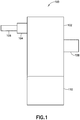
- FIG. 1 is a front view of a derailment detector 100 according to one embodiment.
- the derailment detector 100 is operative for installation on a conventional railway vehicle (not shown) for detecting a derailment condition of the railway vehicle and providing an indication that a derailment condition has occurred.
- the derailment detector 100 is adapted to, upon detection of a derailment condition, discharge a predetermined percentage of full brake pipe pressure of the pneumatic brake system of the railway vehicle. Desirably, derailment detector 100 lowers the brake pipe pressure to a value where an operator would have a clear indication of a reduction in brake pipe pressure without actually initiating braking.
- the discharging of a predetermined percentage of brake pipe pressure is initiated by the activation of derailment detector 100 to pneumatically indicate a derailment condition without activating the brakes of the railway vehicle.
- derailment detector 100 includes an upper assembly 102 having an isolating valve 104 for connecting the derailment detector 100 to a brake pipe 106.
- the isolating valve 104 has a first position in which the derailment detector 100 is in fluid communication with the brake pipe 106 to receive compressed air from the brake pipe 106.
- Isolating valve 104 further has a second position in which the derailment detector 100 is isolated from receiving compressed air from the brake pipe 106. Isolating valve 104 may be manually operated from the first position to the second position.
- the isolating valve 104 may have a powered means, such as an electric, hydraulic, or pneumatic member (not shown) for switching the isolating valve 104 between the first and second positions.
- the upper assembly 102 further includes a brake pipe discharge valve 108, hereafter referred to as "discharge valve 108". Discharge valve 108 is adapted for venting compressed air within the upper assembly 102 to the atmosphere. Upper assembly 102 receives compressed air from the brake pipe 106 and vents a predetermined percentage of the compressed brake pipe air to the atmosphere upon activation of the derailment detector 100.
- derailment detector 100 further includes a lower assembly 110 connected to the upper assembly 102 to define the body of the derailment detector 100.
- the lower assembly 110 defines a shock detection assembly (described with reference to FIGS. 2-3 ) that activates upon detecting an acceleration resulting from vertical and/or horizontal shock vibrations imposed on the railway vehicle to which the derailment detector 100 is attached.
- the lower assembly 110 is adapted to cause an activation of the derailment detector 100 after sensing vertical and/or horizontal acceleration equal to or larger than a preselected value or a preselected range of values, as will be described hereafter.
- the shock detection assembly is adapted not to activate the derailment detector 100 when the vertical and/or horizontal acceleration imposed on the railway vehicle is smaller than a preselected value or a preselected range of values.
- Upper assembly 102 and lower assembly 110 are desirably connected to form a unitary structure. As will be described hereafter, one or more fluid passageways may be provided between the upper assembly 102 and the lower assembly 110 for fluidly connecting the upper assembly 102 and the lower assembly 110. Accordingly, it is desirable that upper assembly 102 is connected to the lower assembly 110 in such manner as to maintain a tight fluid connection therebetween and prevent any fluid leakage at the interface between the upper assembly 102 and the lower assembly 110.
- the upper assembly 102 and the lower assembly 110 may be bolted, welded, glued, or otherwise mechanically fastened to form the body of the derailment detector 100. In another embodiment, the upper assembly 102 and the lower assembly 110 are formed as a single, monolithic structure.
- FIG. 2 a schematic cross-sectional view of the derailment detector 100 is shown in a stand-by mode, where the derailment detector 100 is ready to sense vertical and/or horizontal acceleration imposed on the railway vehicle.
- Upper assembly 102 of derailment detector 100 includes a main chamber 112 in selective fluid communication with the brake pipe 106 through the isolating valve 104 (shown in FIG. 1 ).
- the main chamber 112 receives the compressed air from the brake pipe 106 and includes a main valve 114 slidably disposed inside the main chamber 112.
- the main valve 114 includes a valve rod 116 connected to an upper valve face 118 at an upper portion of the main valve 114.
- the upper valve face 118 defines an upper surface opposite a lower surface.
- the lower surface of the upper valve face 118 includes a first sealing element 120, such as a rubber seal.
- the first sealing element 120 is pressed against a valve seat 122 when main valve 114 is closed to maintain a charge of compressed air within main chamber 112.
- the upper surface of the upper valve face 118 defines a surface for engaging a first elastic member 124, such as a helical coil spring.
- the first elastic member 124 is adapted to compress with movement of main valve 114 where the lower surface of the upper valve face 118 extends away from the valve seat 122.
- main chamber 112 is in fluid connection with an upper chamber 126 through a first pipe 128 and a lower chamber 130 through a second pipe 132.
- Each of the upper and lower chambers 126, 130 is charged with compressed air from the main chamber 112 through first and second chokes 134, 136, respectively, located at an upper portion of first and second pipes 128, 132, respectively.
- a lower valve face 138 of the main valve 114 is provided on a lower portion of the valve rod 116 opposite the upper valve face 118.
- the lower valve face 138 is slidable relative to a wall 140 separating the upper and lower chambers 126, 130.
- a flexible diaphragm 142 seals the lower valve face 138 against the walls of the lower chamber 130 to prevent leakage of compressed air between upper and lower chambers 126, 130.
- Main chamber 112 is in selective fluid communication with an outlet chamber 144 of the discharge valve 108.
- main chamber 112 is in fluid isolation from outlet chamber 144 when the first sealing element 120 of the upper valve face 118 is seated against valve seat 122.
- the main valve 114 is movable within the upper assembly 102 to selectively establish fluid communication with the outlet chamber 144 of the discharge valve 108.
- An axial seal 146 is provided on a lower wall 148 of the outlet chamber 144 to seal the valve rod 116 and prevent the passage of air between the upper chamber 126 and the outlet chamber 144.
- outlet chamber 144 of the discharge valve 108 is sealed by the main valve 114 at one end and an outlet valve 150 at the opposite end to vent the compressed air from the main chamber 112 to the atmosphere when the derailment detector 100 is activated.
- the outlet valve 150 has an outlet valve rod 152 with an outlet valve face 154 provided at its first end and a spring retention member 156 at its second end.
- the spring retention member 156 retains a second elastic member 158, such as a helical coil spring, against a first end of the outlet valve seat 160.
- the spring retention member 156 also defines a surface against which the compressed air acts to activate the outlet valve 150.
- the second end of the outlet valve seat 160 selectively engages the outlet valve face 154 when the derailment detector 100 is activated.
- the outlet valve rod 152 includes a threaded end 162 to threadably receive the outlet valve face 154.
- the threaded connection between the outlet valve rod 152 and the outlet valve face 154 permits the adjustment of the length of the outlet valve rod 152 and a relative separation between the outlet valve face 154 and the spring retention member 156.
- the second elastic member 158 is compressed between the spring retention member 156 and an outer surface of the outlet valve seat 160. Compressing the second elastic member 158 increases the stiffness of the outlet valve 150 and increases the pressure necessary to cause the outlet valve face 154 to move away from the outlet valve seat 160 to allow the passage of compressed air to the atmosphere.
- the stiffness of the outlet valve 150 is set to cause the outlet valve 150 to open at a pressure sufficient to vent 5% of the total pressure from the main chamber 112. Because the main chamber 112 receives the compressed air from the brake pipe 106, the outlet valve 150 also vents 5% of the total brake pipe pressure during normal operation. In another embodiment, the stiffness of the outlet valve 150 is selected to vent between 3-8% of total brake pipe pressure.
- the derailment detector 100 is adapted for releasing a predetermined percentage of brake pipe pressure to give an indication that the derailment detector 100 has been activated, but not release a percentage of brake pipe pressure sufficient to affect braking of the railway vehicle.
- the signal indicator 164 is forced outward from a side of the discharge valve 108 to provide a visual indication that the derailment detector 100 has been activated.
- the signal indicator 164 defines a substantially tubular structure with one or more axial vents 166 extending through a terminal end of the signal indicator 164 and one or more radial vents 168 extending through a tubular sidewall of the signal indicator 164. In a first position, where signal indicator 164 is not activated, the signal indicator 164 is substantially received within the cavity of the outlet chamber 144.
- compressed air acts on the terminal end of the signal indicator 164 and a portion of the compressed air is passed through the axial vents 166.
- the signal indicator 164 is retained in the first position by a ball 170 received within a radial cavity extending radially into a sidewall of the signal indicator 164.
- the ball 170 is urged against the wall of the cavity by a spring 174.
- the pressure of the compressed air passing through the outlet chamber 144 is sufficient to push the signal indicator 164 such that the ball 170 is retracted from the cavity and the signal indicator 164 is advanced out of the outlet chamber 144 to a second position, as shown in FIG. 3 .
- radial vents 168 are advanced out of the outlet chamber 144 and compressed air from the outlet chamber 144 can pass through the axial vents 166 and the radial vents 168.
- signal indicator 164 is advanced relative to the outlet chamber 144 such that the ball 170 engages a second cavity.
- the signal indicator 164 is manually reset by pushing the signal indicator 164 into the outlet chamber 144 of the discharge valve 108 to overcome the force of the spring 174 exerted on the ball 170.
- the lower assembly 110 is fluidly connected to the upper chamber 126 of the upper assembly 102 by a pipe 176.
- the pipe 176 delivers compressed air to a top pressure chamber 178 of the lower assembly 110.
- the top pressure chamber 178 is connected to a bottom pressure chamber 180 by a channel 182.
- a bottom valve 184 is slidably disposed between the top pressure chamber 178 and the bottom pressure chamber 180 adjacent to the channel 182.
- the bottom valve 184 includes a bottom valve face 186 having a second sealing element 188, such as a rubber seal, for sealing the bottom valve face 186 against a bottom valve seat 190.
- the second sealing element 188 is pressed against a bottom valve seat 190 when bottom valve 184 is closed to isolate the top pressure chamber 178 from receiving compressed air.
- the bottom valve 184 is coupled to a vibrating mass 192 by a shock absorbing pin 194.
- the vibrating mass 192 has a generally solid cylindrical shape with an annular opening extending therethrough.
- the inner sidewall of the annular opening of the vibrating mass 192 is threaded to threadably receive an adjustment member 196.
- the vibrating mass 192 is suspended within the bottom pressure chamber 180 on a third elastic member 198, such as a helical coil spring, and is constrained to move in a vertical direction only. Stiffness of the vibrating mass 192 may be changed by adjusting the adjustment member 196 through an opening 200 provided on the bottom of the derailment detector 100. Stiffness of the vibrating mass 192 can be increased by turning the adjustment member 196 to compress the third elastic member 198.
- stiffness of the vibrating mass 192 can be decreased by turning the adjustment member 196 to decompress the third elastic member 198. Stiffness of the vibrating mass 192 is directly proportional to the sensitivity of the derailment detector 100 to acceleration in the vertical direction.
- a lower portion of the vibrating mass 192 includes a diaphragm 202 that seals the bottom pressure chamber 180 from a lower outlet chamber 204.
- the bottom pressure chamber 180 is in fluid communication with the lower outlet chamber 204 through a choke 206.
- One or more vents 208 are provided on the bottom surface of the derailment detector 100 to vent the compressed air from the lower outlet chamber 204.
- the derailment detector 100 is adapted to prevent self-activation during charging. Initially, compressed air from the brake pipe 106 is received inside the main chamber 112 which charges more quickly than upper and lower chambers 126, 130 of the upper assembly 102 because the compressed air is routed to the upper and lower chambers 126, 130 through the first and second chokes 134, 136.
- the first and second chokes 134, 136 prevent the upper and lower chambers 126, 130 from charging with compressed air at a faster rate than the main chamber 112 in order to prevent the lower valve face 138 from being pushed upward under pressure to unseat the upper valve face 118 from the valve seat 122. Such action is undesirable because compressed air would be vented from the main chamber 112 into the outlet chamber 144 and through the discharge valve 108 (see FIG. 3 ).
- the lower assembly 110 is adapted for sensing acceleration in vertical and horizontal directions to cause the operation of the derailment detector 100 after a predetermined acceleration threshold is reached.
- the first activation involves an unbalancing of the bottom valve 184 to cause the bottom valve face 186 to unseat from the bottom valve seat 190.
- Bottom valve 184 is unbalanced as a result of a vertical and/or horizontal acceleration experienced by the railway vehicle. Sensitivity to acceleration in the vertical direction is controlled by the vibrating mass 192 while sensitivity to acceleration in the horizontal acceleration is controlled by the shock absorbing pin 194.
- the stiffness of the vibrating mass 192 may be set to cause unbalancing of the bottom valve 184 via the shock absorbing pin 194 at a predetermined force between 6-11.5g in a vertical direction. This means that the derailment detector 100 must activated after sensing vertical acceleration force exceeding 11.5g. In other embodiments, unbalancing of the bottom valve 184 may be set to occur at any value between 6g and 11.5g.
- sensitivity to acceleration in a horizontal direction is controlled by the unbalancing of shock absorbing pin 194 in a horizontal direction relative to the vibrating mass 192 that is fixed in a horizontal direction relative to the body of derailment detector 100.
- the shock absorbing pin 194 may be set to cause unbalancing of the bottom valve 184 at a predetermined force of 30g in a horizontal direction. This means that the derailment detector 100 must be activated after sensing horizontal acceleration force exceeding 30g. Horizontal acceleration of less than 30g would not cause an activation of the derailment detector 100.
- Sensitivity threshold of the derailment detector 100 to horizontal acceleration is higher than the sensitivity threshold to vertical acceleration in order to prevent false activations to horizontal acceleration experienced by the railway vehicle during coupling, starting, and stopping.
- the bottom valve 184 is separated from the bottom valve seat 190 such that a quantity of compressed air is introduced into the bottom pressure chamber 180.
- the bottom valve 184 is kept open due to the advancing pressure such that compressed air fills the bottom pressure chamber 180 and passes to the lower outlet chamber through the channel 182 and the choke 206. Compressed air then passes through the one or more vents 208 and is exhausted into the atmosphere.
- the second stage of activation of the derailment detector 100 occurs as a direct result of the first stage of activation described above. Due to the pressure drop in the upper chamber 126 caused by the passage of compressed gas through the pipe 176 into the lower assembly 110, a pressure equilibrium between the upper and lower chambers 126, 130 is unbalanced. Because the pressure in the lower chamber 130 is higher than the pressure in the upper chamber 126, lower valve face 138 is pushed upward. Because the lower valve face 138 is connected to the upper valve face 118 through the valve rod 116, the upper valve face 118 is also lifted upward against the force of the first elastic member 124. This movement causes the first sealing element 120 to move away from the valve seat 122 such that compressed air from the main chamber 112 can flow into the outlet chamber 144.
- the pressure inside the outlet chamber 144 acts against the spring retention member 156 of the outlet valve 150 to urge the outlet valve 150 to open and release the compressed air toward the signal indicator 164.
- the signal indicator 164 is retracted into the body of the discharge valve 108 ( FIG. 2 ) and an initial quantity of compressed air is discharged into the atmosphere through axial vents 166.
- the compressed air inside the outlet chamber 144 urges the signal indicator 164 outward such that compressed air is discharged both through the axial vents 166 and the radial vents 168. Movement of the signal indicator 164 outside the outlet chamber 144 of the discharge valve 108 provides a visual indication that the derailment detector 100 has been activated.
- the outlet valve 150 is adjusted to release a predetermined percentage of brake pressure sufficient to give an indication that an abnormal condition (i.e., derailment) has occurred, but insufficient to cause braking of the railway vehicle.
- the predetermined drop in the normal brake pipe pressure gives an indication to the operator of the railway vehicle that an abnormal condition has occurred and that an appropriate corrective action should be taken so that the railway vehicle can be brought to a stop in a safe location.
- the predetermined pressure drop in the brake pipe pressure may be 5% of the normal operating brake pipe pressure.
- the derailment detector 100 After the derailment detector 100 is activated, it must be reset before next use. In order to restore the main valve 114 to its initial, stand-by state, the derailment detector 100 is isolated from the brake pipe 106 so that the compressed air can be exhausted from the main chamber 112 and the outlet chamber 144. The derailment detector 100 is isolated from the brake pipe 106 by closing the isolating valve 104. Once the compressed air is exhausted from the main chamber 112, the main valve 114 is returned to its initial stand-by state by the restoring force of the first elastic member 124. Similarly, because the pressure in the top pressure chamber 178 of the lower assembly 110 is reduced to atmospheric pressure, bottom valve 184 is forced to its initial stand-by state by the restoring force of the third elastic member 198.
- the isolating valve 104 may be opened to introduce the compressed air from the brake pipe 106 into the main chamber 112 and return the derailment detector 100 into its stand-by state shown in FIG. 2 .
Landscapes
- Engineering & Computer Science (AREA)
- Mechanical Engineering (AREA)
- Transportation (AREA)
- Health & Medical Sciences (AREA)
- Biomedical Technology (AREA)
- General Health & Medical Sciences (AREA)
- Valves And Accessory Devices For Braking Systems (AREA)
Description
- This disclosure relates generally to a derailment detector and method and, particularly, to a derailment detector and a method for detecting and signaling a derailment condition in a railway vehicle.
- Derailments in the rail industry often result in substantial damage to railway vehicles and tracks, as well as a significant loss in revenue to operators due to the derailed railway vehicle and/or the track being out of operation. The serious consequences resulting from the derailment of railway vehicles have led to the development of derailment detectors adapted to detect a derailment of the railway vehicle and immediately apply the appropriate corrective measure. Conventional derailment detectors typically activate a full emergency brake function upon derailment detection. While the ultimate goal in a derailment situation is to stop the railway vehicle as soon as possible, certain situations, such as derailment in a tunnel, on a bridge, or during a false activation, demand an alternative means of initiating the stopping procedure.
- In particular, systems based on an inertia sensor are known where, upon activation of the inertia sensor, the pressure inside the brake pipe is quickly released to cause the emergency brake application of the railway vehicle that acts on all cars in the composition. Within the prior art, United States Patent No.
5,188,038 to Shanley is directed to a railroad car derailment safety device that activates the air-brake system immediately upon detection of a derailment condition. The device includes a bar extension projecting from a bottom portion of each car to a position slightly above the rail. Upon railroad car derailment, the bar contacts the rail, causing a trip valve in the air-brake line to open and release the pressure in the brake line, thereby applying the brakes. Derailment detectors of this type function as emergency brace valves. - However, conventional derailment detectors have a major drawback in that full braking force is applied to stop the railway vehicle as quickly as possible in a shortest possible distance. While the ultimate goal is to safely bring the railway vehicle to a complete stop, emergency brake application upon derailment detection can result in the stopping of the railway vehicle in an undesirable location, such as inside a tunnel or on a bridge. This complicates the effort to repair the derailed vehicle and/or the track, and resume normal railway travel.
- Certain efforts have been made to develop derailment detectors which alert the operator of the railway vehicle that a derailment condition has occurred. For example, United States Patent No.
3,994,459 to Miller et al. is directed to a railway vehicle derailment detection system having an acceleration responsive device that, in response to the changes in vertical acceleration of the vehicle as a result of the derailment, sends a radio signal installed in the engine to provide a visual or an audio alert to the operator. The acceleration responsive device is embodied as a piezo-electric element that is operative for transmitting an electrical signal when the sensor element is activated as a result of vehicle derailment. The system described in this patent does not include a pneumatic means for providing an indication to the operator that a derailment situation arose. Other state of the art derailment detectors are described in the documentsDE 10 2009 056931 A1 andEP 1 914 134 A1 . - While various derailment detectors are known in the railway industry, improved derailment detectors which do not cause an application of emergency brakes are desired. Additionally, improved derailment detectors utilizing the pneumatic system of the railway vehicle are also desired in the railway field. Moreover, the railway industry continues to demand improved derailment detectors having improved structures and economies of manufacture.
- In view of the disadvantages associated with the prior art derailment detectors, it is desirable to provide an improved derailment detector that, upon detection of a derailment condition, causes a predetermined reduction in brake pipe pressure to alert the operator that an abnormal operating condition has occurred and that the railway vehicle should be brought to a complete stop at a safe location. While various embodiments of a derailment detector and a method for detecting and signaling a derailment condition in a railway vehicle are described in detail herein, one embodiment of derailment detector for a railway vehicle may include a housing in fluid communication with a brake pipe of the railway vehicle to receive compressed air from a pneumatic braking system. The derailment detector may further include a main chamber disposed within the housing and pressurized by the compressed air. The main chamber may have a main valve. A shock detection assembly may be adapted for detecting an acceleration indicative of a derailment condition to activate the main valve upon detection of the acceleration indicative of the derailment condition. The derailment detector may further include a discharge valve in selective fluid communication with the main chamber. Upon detection of the acceleration indicative of the derailment condition, the discharge valve may be operative for discharging a predetermined amount of the compressed air from the main chamber to indicate that the derailment condition has occurred.
- In accordance with another embodiment, the discharge valve may include a signal indicator movable relative to the discharge valve by the discharge of the predetermined amount of pressure to indicate the occurrence of the derailment condition. The predetermined amount of pressure may be 3-8% of total pressure in the pneumatic braking system. In another embodiment, the predetermined amount of pressure may be 5% of the total pressure in the pneumatic braking system. The discharge valve may be adjustable to select the amount of pressure discharged from the pneumatic braking system. The derailment detector may further include an isolation valve to selectively control a flow of compressed air from the brake pipe to the housing.
- According to yet another embodiment, the housing may include an upper assembly having the main chamber and a lower assembly having the shock detection assembly. The upper assembly may be in fluid communication with the lower assembly. The shock detection assembly may include a vibrating mass suspended on a spring, the vibrating mass adapted for detecting acceleration in a substantially vertical direction. The vibrating mass may be adjustable to select a vertical acceleration at which the discharge valve is activated.
- In another embodiment, a derailment detector may include a discharge valve adapted to discharge a predetermined amount of pressure from a pneumatic braking system of a railway vehicle in response to a detection of an acceleration indicative of a derailment condition. The discharge valve may further include a signal indicator movable relative to the discharge valve by the discharge of the predetermined amount of pressure to indicate the occurrence of the derailment condition. The predetermined amount of pressure may be 3-8% of total pressure in the pneumatic braking system. In one embodiment, the predetermined amount of pressure may be 5% of the total pressure in the pneumatic braking system. The discharge valve may be adjustable to select the amount of pressure discharged from the pneumatic braking system. The discharge valve may be activated by a shock detection assembly adapted for detecting an acceleration indicative of the derailment condition.
- In another embodiment, a method of detecting a derailment condition in a railway vehicle and indicating the occurrence of the derailment condition may include the steps of:
- (a) pressurizing a derailment detector with compressed air; (b) detecting an acceleration indicative of the derailment condition; and (c) discharging a predetermined amount of the compressed air from the derailment detector to indicate the occurrence of the derailment condition. The derailment detector may be pressurized with compressed air received from a pneumatic braking system of the railway vehicle. The acceleration indicative of the derailment condition may be detected by a shock detection assembly. The predetermined amount of compressed air may be discharged through a discharge valve.
- These and other features and characteristics of the derailment detector, as well as the methods of manufacture and functions of the related elements of structures and the combination of parts and economies of manufacture, will become more apparent upon consideration of the following description and the appended claims with reference to the accompanying drawings, all of which form a part of this specification, wherein like reference numerals designate corresponding parts in the various figures. It is to be expressly understood, however, that the drawings are for the purpose of illustration and description only and are not intended as a definition of the limits of the invention. As used in the specification and the claims, the singular form of "a", "an", and "the" include plural referents unless the context clearly dictates otherwise.
-
-
FIG. 1 is a front view of a derailment detector according to one embodiment. -
FIG. 2 is a schematic cross-sectional view of the derailment detector ofFIG. 1 in a stand-by mode. -
FIG. 3 is a schematic cross-sectional view of the derailment detector ofFIG. 1 in an active mode. - For purposes of the description hereinafter, spatial orientation terms, as used, shall relate to the referenced embodiment as it is oriented in the accompanying drawing figures or otherwise described in the following detailed description. However, it is to be understood that the embodiments described hereinafter may assume many alternative variations and configurations. It is also to be understood that the specific components, devices, and features illustrated in the accompanying drawing figures and described herein are simply exemplary and should not be considered as limiting.
-
FIG. 1 is a front view of aderailment detector 100 according to one embodiment. Thederailment detector 100 is operative for installation on a conventional railway vehicle (not shown) for detecting a derailment condition of the railway vehicle and providing an indication that a derailment condition has occurred. Thederailment detector 100 is adapted to, upon detection of a derailment condition, discharge a predetermined percentage of full brake pipe pressure of the pneumatic brake system of the railway vehicle. Desirably,derailment detector 100 lowers the brake pipe pressure to a value where an operator would have a clear indication of a reduction in brake pipe pressure without actually initiating braking. As will be described hereinafter, the discharging of a predetermined percentage of brake pipe pressure is initiated by the activation ofderailment detector 100 to pneumatically indicate a derailment condition without activating the brakes of the railway vehicle. - With continuing reference to
FIG. 1 ,derailment detector 100 includes anupper assembly 102 having an isolatingvalve 104 for connecting thederailment detector 100 to abrake pipe 106. The isolatingvalve 104 has a first position in which thederailment detector 100 is in fluid communication with thebrake pipe 106 to receive compressed air from thebrake pipe 106. Isolatingvalve 104 further has a second position in which thederailment detector 100 is isolated from receiving compressed air from thebrake pipe 106. Isolatingvalve 104 may be manually operated from the first position to the second position. Alternatively, or in addition, the isolatingvalve 104 may have a powered means, such as an electric, hydraulic, or pneumatic member (not shown) for switching the isolatingvalve 104 between the first and second positions. Theupper assembly 102 further includes a brakepipe discharge valve 108, hereafter referred to as "discharge valve 108".Discharge valve 108 is adapted for venting compressed air within theupper assembly 102 to the atmosphere.Upper assembly 102 receives compressed air from thebrake pipe 106 and vents a predetermined percentage of the compressed brake pipe air to the atmosphere upon activation of thederailment detector 100. - With continuing reference to
FIG. 1 ,derailment detector 100 further includes alower assembly 110 connected to theupper assembly 102 to define the body of thederailment detector 100. Thelower assembly 110 defines a shock detection assembly (described with reference toFIGS. 2-3 ) that activates upon detecting an acceleration resulting from vertical and/or horizontal shock vibrations imposed on the railway vehicle to which thederailment detector 100 is attached. Thelower assembly 110 is adapted to cause an activation of thederailment detector 100 after sensing vertical and/or horizontal acceleration equal to or larger than a preselected value or a preselected range of values, as will be described hereafter. The shock detection assembly is adapted not to activate thederailment detector 100 when the vertical and/or horizontal acceleration imposed on the railway vehicle is smaller than a preselected value or a preselected range of values. -
Upper assembly 102 andlower assembly 110 are desirably connected to form a unitary structure. As will be described hereafter, one or more fluid passageways may be provided between theupper assembly 102 and thelower assembly 110 for fluidly connecting theupper assembly 102 and thelower assembly 110. Accordingly, it is desirable thatupper assembly 102 is connected to thelower assembly 110 in such manner as to maintain a tight fluid connection therebetween and prevent any fluid leakage at the interface between theupper assembly 102 and thelower assembly 110. Theupper assembly 102 and thelower assembly 110 may be bolted, welded, glued, or otherwise mechanically fastened to form the body of thederailment detector 100. In another embodiment, theupper assembly 102 and thelower assembly 110 are formed as a single, monolithic structure. - With reference to
FIG. 2 , a schematic cross-sectional view of thederailment detector 100 is shown in a stand-by mode, where thederailment detector 100 is ready to sense vertical and/or horizontal acceleration imposed on the railway vehicle.Upper assembly 102 ofderailment detector 100 includes amain chamber 112 in selective fluid communication with thebrake pipe 106 through the isolating valve 104 (shown inFIG. 1 ). Themain chamber 112 receives the compressed air from thebrake pipe 106 and includes amain valve 114 slidably disposed inside themain chamber 112. Themain valve 114 includes avalve rod 116 connected to anupper valve face 118 at an upper portion of themain valve 114. Theupper valve face 118 defines an upper surface opposite a lower surface. The lower surface of theupper valve face 118 includes afirst sealing element 120, such as a rubber seal. Thefirst sealing element 120 is pressed against avalve seat 122 whenmain valve 114 is closed to maintain a charge of compressed air withinmain chamber 112. The upper surface of theupper valve face 118 defines a surface for engaging a firstelastic member 124, such as a helical coil spring. The firstelastic member 124 is adapted to compress with movement ofmain valve 114 where the lower surface of theupper valve face 118 extends away from thevalve seat 122. - With continuing reference to
FIG. 2 ,main chamber 112 is in fluid connection with anupper chamber 126 through afirst pipe 128 and alower chamber 130 through asecond pipe 132. Each of the upper andlower chambers main chamber 112 through first andsecond chokes second pipes lower valve face 138 of themain valve 114 is provided on a lower portion of thevalve rod 116 opposite theupper valve face 118. Thelower valve face 138 is slidable relative to awall 140 separating the upper andlower chambers flexible diaphragm 142 seals thelower valve face 138 against the walls of thelower chamber 130 to prevent leakage of compressed air between upper andlower chambers -
Main chamber 112 is in selective fluid communication with anoutlet chamber 144 of thedischarge valve 108. As will be described hereafter,main chamber 112 is in fluid isolation fromoutlet chamber 144 when thefirst sealing element 120 of theupper valve face 118 is seated againstvalve seat 122. When thefirst sealing element 120 moves away from thevalve seat 122, fluid communication is established between themain chamber 112 and theoutlet chamber 144 of thedischarge valve 108 such that theoutlet chamber 144 receives the compressed air from themain chamber 112. Thus, themain valve 114 is movable within theupper assembly 102 to selectively establish fluid communication with theoutlet chamber 144 of thedischarge valve 108. Anaxial seal 146 is provided on alower wall 148 of theoutlet chamber 144 to seal thevalve rod 116 and prevent the passage of air between theupper chamber 126 and theoutlet chamber 144. - With continuing reference to
FIG. 2 ,outlet chamber 144 of thedischarge valve 108 is sealed by themain valve 114 at one end and anoutlet valve 150 at the opposite end to vent the compressed air from themain chamber 112 to the atmosphere when thederailment detector 100 is activated. Theoutlet valve 150 has anoutlet valve rod 152 with anoutlet valve face 154 provided at its first end and aspring retention member 156 at its second end. Thespring retention member 156 retains a secondelastic member 158, such as a helical coil spring, against a first end of theoutlet valve seat 160. Thespring retention member 156 also defines a surface against which the compressed air acts to activate theoutlet valve 150. The second end of theoutlet valve seat 160 selectively engages theoutlet valve face 154 when thederailment detector 100 is activated. - The
outlet valve rod 152 includes a threadedend 162 to threadably receive theoutlet valve face 154. The threaded connection between theoutlet valve rod 152 and theoutlet valve face 154 permits the adjustment of the length of theoutlet valve rod 152 and a relative separation between theoutlet valve face 154 and thespring retention member 156. By threading theoutlet valve face 154 toward thespring retention member 156, the secondelastic member 158 is compressed between thespring retention member 156 and an outer surface of theoutlet valve seat 160. Compressing the secondelastic member 158 increases the stiffness of theoutlet valve 150 and increases the pressure necessary to cause theoutlet valve face 154 to move away from theoutlet valve seat 160 to allow the passage of compressed air to the atmosphere. Conversely, decompressing the secondelastic member 158 reduces the stiffness of theoutlet valve 150 and decreases the pressure necessary to cause theoutlet valve face 154 to move away from theoutlet valve seat 160 to vent the compressed air to the atmosphere. Thus, the adjustability of theoutlet valve 150 allows for selecting a desired pressure necessary to open theoutlet valve 150. In one embodiment, the stiffness of theoutlet valve 150 is set to cause theoutlet valve 150 to open at a pressure sufficient to vent 5% of the total pressure from themain chamber 112. Because themain chamber 112 receives the compressed air from thebrake pipe 106, theoutlet valve 150 also vents 5% of the total brake pipe pressure during normal operation. In another embodiment, the stiffness of theoutlet valve 150 is selected to vent between 3-8% of total brake pipe pressure. Desirably, less than 10% of total brake pipe pressure is vented through theoutlet valve 150 because such pressure drop would necessarily cause an application of the brakes of the railway vehicle. Thederailment detector 100 is adapted for releasing a predetermined percentage of brake pipe pressure to give an indication that thederailment detector 100 has been activated, but not release a percentage of brake pipe pressure sufficient to affect braking of the railway vehicle. - Compressed air passing through the
outlet chamber 144 of thedischarge valve 108 upon activation of thederailment detector 100 engages asignal indicator 164 which is movably disposed within the terminal end of theoutlet chamber 144. Thesignal indicator 164 is forced outward from a side of thedischarge valve 108 to provide a visual indication that thederailment detector 100 has been activated. Thesignal indicator 164 defines a substantially tubular structure with one or moreaxial vents 166 extending through a terminal end of thesignal indicator 164 and one or moreradial vents 168 extending through a tubular sidewall of thesignal indicator 164. In a first position, wheresignal indicator 164 is not activated, thesignal indicator 164 is substantially received within the cavity of theoutlet chamber 144. Upon activation of thederailment detector 100, compressed air acts on the terminal end of thesignal indicator 164 and a portion of the compressed air is passed through theaxial vents 166. Initially, as shown inFIG. 2 , thesignal indicator 164 is retained in the first position by aball 170 received within a radial cavity extending radially into a sidewall of thesignal indicator 164. Theball 170 is urged against the wall of the cavity by aspring 174. The pressure of the compressed air passing through theoutlet chamber 144 is sufficient to push thesignal indicator 164 such that theball 170 is retracted from the cavity and thesignal indicator 164 is advanced out of theoutlet chamber 144 to a second position, as shown inFIG. 3 . In the second position,radial vents 168 are advanced out of theoutlet chamber 144 and compressed air from theoutlet chamber 144 can pass through theaxial vents 166 and the radial vents 168. Upon activation,signal indicator 164 is advanced relative to theoutlet chamber 144 such that theball 170 engages a second cavity. Thesignal indicator 164 is manually reset by pushing thesignal indicator 164 into theoutlet chamber 144 of thedischarge valve 108 to overcome the force of thespring 174 exerted on theball 170. - With continuing reference to
FIG. 2 , thelower assembly 110 is fluidly connected to theupper chamber 126 of theupper assembly 102 by apipe 176. Thepipe 176 delivers compressed air to atop pressure chamber 178 of thelower assembly 110. Thetop pressure chamber 178 is connected to abottom pressure chamber 180 by achannel 182. Abottom valve 184 is slidably disposed between thetop pressure chamber 178 and thebottom pressure chamber 180 adjacent to thechannel 182. Thebottom valve 184 includes abottom valve face 186 having asecond sealing element 188, such as a rubber seal, for sealing thebottom valve face 186 against abottom valve seat 190. Thesecond sealing element 188 is pressed against abottom valve seat 190 whenbottom valve 184 is closed to isolate thetop pressure chamber 178 from receiving compressed air. - The
bottom valve 184 is coupled to a vibratingmass 192 by ashock absorbing pin 194. The vibratingmass 192 has a generally solid cylindrical shape with an annular opening extending therethrough. The inner sidewall of the annular opening of the vibratingmass 192 is threaded to threadably receive anadjustment member 196. The vibratingmass 192 is suspended within thebottom pressure chamber 180 on a thirdelastic member 198, such as a helical coil spring, and is constrained to move in a vertical direction only. Stiffness of the vibratingmass 192 may be changed by adjusting theadjustment member 196 through anopening 200 provided on the bottom of thederailment detector 100. Stiffness of the vibratingmass 192 can be increased by turning theadjustment member 196 to compress the thirdelastic member 198. Conversely, stiffness of the vibratingmass 192 can be decreased by turning theadjustment member 196 to decompress the thirdelastic member 198. Stiffness of the vibratingmass 192 is directly proportional to the sensitivity of thederailment detector 100 to acceleration in the vertical direction. A lower portion of the vibratingmass 192 includes adiaphragm 202 that seals thebottom pressure chamber 180 from alower outlet chamber 204. Thebottom pressure chamber 180 is in fluid communication with thelower outlet chamber 204 through achoke 206. One ormore vents 208 are provided on the bottom surface of thederailment detector 100 to vent the compressed air from thelower outlet chamber 204. - Having described the components of the
derailment detector 100, a charging procedure to initialize thederailment detector 100 in a stand-by state shown inFIG. 2 will now be described. Thederailment detector 100 is adapted to prevent self-activation during charging. Initially, compressed air from thebrake pipe 106 is received inside themain chamber 112 which charges more quickly than upper andlower chambers upper assembly 102 because the compressed air is routed to the upper andlower chambers second chokes second chokes lower chambers main chamber 112 in order to prevent thelower valve face 138 from being pushed upward under pressure to unseat theupper valve face 118 from thevalve seat 122. Such action is undesirable because compressed air would be vented from themain chamber 112 into theoutlet chamber 144 and through the discharge valve 108 (seeFIG. 3 ). - During charging, compressed air from the
upper chamber 126 is introduced into thebottom pressure chamber 180 in thelower assembly 110 through thepipe 176. The stiffness of the vibratingmass 192 is sufficiently high to keep thebottom valve face 186 sealed against thebottom valve seat 190 and prevent the compressed air from being discharged through thelower assembly 110. In the stand-by state illustrated inFIG. 2 , thelower assembly 110 is not activated and thederailment detector 100 is stable. Once fully charged such that the pressure inside themain chamber 112 and the upper andlower chambers brake pipe 106, thederailment detector 100 is operative in stand-by state and ready for detection of a derailment condition, as will be described next. - With reference to
FIG. 3 , two separate but related activations take place during activation ofderailment detector 100. As described above, thelower assembly 110 is adapted for sensing acceleration in vertical and horizontal directions to cause the operation of thederailment detector 100 after a predetermined acceleration threshold is reached. The first activation involves an unbalancing of thebottom valve 184 to cause thebottom valve face 186 to unseat from thebottom valve seat 190.Bottom valve 184 is unbalanced as a result of a vertical and/or horizontal acceleration experienced by the railway vehicle. Sensitivity to acceleration in the vertical direction is controlled by the vibratingmass 192 while sensitivity to acceleration in the horizontal acceleration is controlled by theshock absorbing pin 194. For example, the stiffness of the vibratingmass 192 may be set to cause unbalancing of thebottom valve 184 via theshock absorbing pin 194 at a predetermined force between 6-11.5g in a vertical direction. This means that thederailment detector 100 must activated after sensing vertical acceleration force exceeding 11.5g. In other embodiments, unbalancing of thebottom valve 184 may be set to occur at any value between 6g and 11.5g. - Similarly, sensitivity to acceleration in a horizontal direction is controlled by the unbalancing of
shock absorbing pin 194 in a horizontal direction relative to the vibratingmass 192 that is fixed in a horizontal direction relative to the body ofderailment detector 100. For example, theshock absorbing pin 194 may be set to cause unbalancing of thebottom valve 184 at a predetermined force of 30g in a horizontal direction. This means that thederailment detector 100 must be activated after sensing horizontal acceleration force exceeding 30g. Horizontal acceleration of less than 30g would not cause an activation of thederailment detector 100. Sensitivity threshold of thederailment detector 100 to horizontal acceleration is higher than the sensitivity threshold to vertical acceleration in order to prevent false activations to horizontal acceleration experienced by the railway vehicle during coupling, starting, and stopping. - During the first stage of activation of the
derailment detector 100, thebottom valve 184 is separated from thebottom valve seat 190 such that a quantity of compressed air is introduced into thebottom pressure chamber 180. Thebottom valve 184 is kept open due to the advancing pressure such that compressed air fills thebottom pressure chamber 180 and passes to the lower outlet chamber through thechannel 182 and thechoke 206. Compressed air then passes through the one ormore vents 208 and is exhausted into the atmosphere. - The second stage of activation of the
derailment detector 100 occurs as a direct result of the first stage of activation described above. Due to the pressure drop in theupper chamber 126 caused by the passage of compressed gas through thepipe 176 into thelower assembly 110, a pressure equilibrium between the upper andlower chambers lower chamber 130 is higher than the pressure in theupper chamber 126,lower valve face 138 is pushed upward. Because thelower valve face 138 is connected to theupper valve face 118 through thevalve rod 116, theupper valve face 118 is also lifted upward against the force of the firstelastic member 124. This movement causes thefirst sealing element 120 to move away from thevalve seat 122 such that compressed air from themain chamber 112 can flow into theoutlet chamber 144. The pressure inside theoutlet chamber 144 acts against thespring retention member 156 of theoutlet valve 150 to urge theoutlet valve 150 to open and release the compressed air toward thesignal indicator 164. Initially, thesignal indicator 164 is retracted into the body of the discharge valve 108 (FIG. 2 ) and an initial quantity of compressed air is discharged into the atmosphere throughaxial vents 166. However, the compressed air inside theoutlet chamber 144 urges thesignal indicator 164 outward such that compressed air is discharged both through theaxial vents 166 and the radial vents 168. Movement of thesignal indicator 164 outside theoutlet chamber 144 of thedischarge valve 108 provides a visual indication that thederailment detector 100 has been activated. Theoutlet valve 150 is adjusted to release a predetermined percentage of brake pressure sufficient to give an indication that an abnormal condition (i.e., derailment) has occurred, but insufficient to cause braking of the railway vehicle. The predetermined drop in the normal brake pipe pressure gives an indication to the operator of the railway vehicle that an abnormal condition has occurred and that an appropriate corrective action should be taken so that the railway vehicle can be brought to a stop in a safe location. In one embodiment, the predetermined pressure drop in the brake pipe pressure may be 5% of the normal operating brake pipe pressure. - After the
derailment detector 100 is activated, it must be reset before next use. In order to restore themain valve 114 to its initial, stand-by state, thederailment detector 100 is isolated from thebrake pipe 106 so that the compressed air can be exhausted from themain chamber 112 and theoutlet chamber 144. Thederailment detector 100 is isolated from thebrake pipe 106 by closing the isolatingvalve 104. Once the compressed air is exhausted from themain chamber 112, themain valve 114 is returned to its initial stand-by state by the restoring force of the firstelastic member 124. Similarly, because the pressure in thetop pressure chamber 178 of thelower assembly 110 is reduced to atmospheric pressure,bottom valve 184 is forced to its initial stand-by state by the restoring force of the thirdelastic member 198. After returning thesignal indicator 164 into its initial position inside thedischarge valve 108, the isolatingvalve 104 may be opened to introduce the compressed air from thebrake pipe 106 into themain chamber 112 and return thederailment detector 100 into its stand-by state shown inFIG. 2 . - While embodiments of a
derailment detector 100 and methods of operation thereof were provided in the foregoing description, those skilled in the art may make modifications and alterations to these embodiments without departing from the scope of the invention. Accordingly, the foregoing description is intended to be illustrative rather than restrictive.
Claims (15)
- A derailment detector (100) for a railway vehicle, the derailment detector (100) comprising:a housing in fluid communication with a brake pipe (106) of the railway vehicle to receive compressed air from a pneumatic braking system;a main chamber (112) disposed within the housing and pressurized by the compressed air, the main chamber (112) having a main valve (114);a shock detection assembly adapted for detecting an acceleration indicative of a derailment condition and activating the main valve (114) upon detection of the acceleration indicative of the derailment condition; anda discharge valve (108) in selective fluid communication with the main chamber (112),wherein, upon detection of the acceleration indicative of the derailment condition, the discharge valve (108) is operative for discharging a predetermined percentage of full operating brake pipe pressure of the compressed air from the main chamber (112) to indicate that the derailment condition has occurred, but not release a percentage of the full operating brake pipe pressure sufficient to affect braking of the railway vehicle.
- The derailment detector (100) of claim 1, wherein the discharge valve (108) further comprises a signal indicator (164) movable relative to the discharge valve (108) by the discharge of the predetermined amount of pressure to indicate the occurrence of the derailment condition.
- The derailment detector (100) of claim 1, wherein the predetermined amount of pressure is 3-8%, preferably 5%, of total pressure in the pneumatic braking system.
- The derailment detector (100) of claim 1, wherein the discharge valve (108) is adjustable to select the percentage of full operating brake pipe pressure discharged from the pneumatic braking system.
- The derailment detector (100) of claim 1, further comprising an isolation valve (104) to selectively control a flow of compressed air from the brake pipe (106) to the housing.
- The derailment detector (100) of claim 1, wherein the housing further comprises an upper assembly (102) having the main chamber (112) and a lower assembly (110) having the shock detection assembly, wherein in particular the upper assembly (102) is in fluid communication with the lower assembly (110).
- The derailment detector (100) of claim 1, wherein the shock detection assembly includes a vibrating mass (192) suspended on a spring (198), the vibrating mass (192) adapted for detecting acceleration in a substantially vertical direction, wherein in particular the vibrating mass (192) is adjustable to select a vertical acceleration at which the discharge valve (108) is activated.
- A derailment detector (100) comprising:
a discharge valve (108) adapted to discharge a predetermined percentage of full operating brake pipe pressure of a railway vehicle in response to a detection of an acceleration indicative of a derailment condition, but not release a percentage of the full operating brake pipe pressure sufficient to affect braking of the railway vehicle. - The derailment detector (100) of claim 8, wherein the discharge valve (108) further comprises a signal indicator (164) movable relative to the discharge valve (108) by the discharge of the predetermined percentage of full operating brake pipe pressure to indicate the occurrence of the derailment condition.
- The derailment detector (100) of claim 8, wherein the predetermined amount of pressure is 3-8%, preferably 5%, of total pressure in the pneumatic braking system.
- The derailment detector (100) of claim 8, wherein the discharge valve (108) is adjustable to select the percentage of full operating brake pipe pressure discharged from the pneumatic braking system.
- The derailment detector (100) of claim 8, wherein the discharge valve (108) is activated by a shock detection assembly adapted for detecting an acceleration indicative of the derailment condition.
- A method of detecting a derailment condition in a railway vehicle and indicating the occurrence of the derailment condition, the method comprising the steps of:pressurizing a derailment detector (100) with compressed air;detecting an acceleration indicative of the derailment condition; anddischarging a predetermined percentage of full operating brake pipe pressure of the compressed air from the derailment detector (100) to indicate the occurrence of the derailment condition, but not release a percentage of the full operating brake pipe pressure sufficient to affect braking of the railway vehicle.
- The method of claim 13, wherein the derailment detector (100) is pressurized with compressed air received from a pneumatic braking system of the railway vehicle.
- The method of claim 13, wherein the acceleration indicative of the derailment condition is detected by a shock detection assembly and the predetermined percentage of full operating brake pipe pressure of compressed air is discharged through a discharge valve (108).
Applications Claiming Priority (2)
| Application Number | Priority Date | Filing Date | Title |
|---|---|---|---|
| US13/803,373 US9139209B2 (en) | 2013-03-14 | 2013-03-14 | Derailment detector |
| PCT/US2014/011996 WO2014143409A1 (en) | 2013-03-14 | 2014-01-17 | Derailment detector |
Publications (2)
| Publication Number | Publication Date |
|---|---|
| EP2969674A1 EP2969674A1 (en) | 2016-01-20 |
| EP2969674B1 true EP2969674B1 (en) | 2019-11-27 |
Family
ID=50064792
Family Applications (1)
| Application Number | Title | Priority Date | Filing Date |
|---|---|---|---|
| EP14703006.8A Active EP2969674B1 (en) | 2013-03-14 | 2014-01-17 | Derailment detector |
Country Status (10)
| Country | Link |
|---|---|
| US (1) | US9139209B2 (en) |
| EP (1) | EP2969674B1 (en) |
| JP (1) | JP6145561B2 (en) |
| KR (1) | KR102002079B1 (en) |
| CN (1) | CN105073521B (en) |
| AU (1) | AU2014228686B2 (en) |
| BR (1) | BR112015021270B1 (en) |
| CA (1) | CA2900972C (en) |
| RU (1) | RU2614407C1 (en) |
| WO (1) | WO2014143409A1 (en) |
Families Citing this family (5)
| Publication number | Priority date | Publication date | Assignee | Title |
|---|---|---|---|---|
| US9139209B2 (en) * | 2013-03-14 | 2015-09-22 | Wabtec Holding Corp. | Derailment detector |
| FR3014400B1 (en) * | 2013-12-11 | 2016-02-05 | Alstom Transport Sa | LAND VEHICLE GUIDE COMPRISING A DEVICE FOR MANAGING A DERAILMENT OF THE VEHICLE, AND METHOD FOR MANAGING THE DERAILMENT THEREOF |
| KR102049295B1 (en) * | 2018-01-02 | 2019-11-27 | 주식회사 고려차량 | Apparatus for detecting derailment of train and train having the same |
| KR102499650B1 (en) * | 2022-11-24 | 2023-02-14 | 주식회사 주은기공 | Derailment detector for train |
| CN116373812B (en) * | 2023-05-29 | 2023-09-05 | 四川永森航空材料科技有限公司 | Automatic train derailment braking device and braking method |
Family Cites Families (47)
| Publication number | Priority date | Publication date | Assignee | Title |
|---|---|---|---|---|
| US532795A (en) | 1895-01-22 | Armature for dynamo-electric machines or motors | ||
| US739918A (en) | 1902-07-23 | 1903-09-29 | Robert A Parke | Inertia-governor for fluid-pressure brakes. |
| US788744A (en) * | 1904-06-16 | 1905-05-02 | John B Wright | Safety attachment for car-trucks. |
| US909320A (en) * | 1908-08-04 | 1909-01-12 | Warren D Mcpherson | Automatic air and gas valve for cars. |
| US1042869A (en) | 1910-06-21 | 1912-10-29 | Hugh Sinclair Beattie | Emergency-brake-setting device. |
| US998513A (en) | 1910-06-28 | 1911-07-18 | Carl Hill | Emergency appliance for air-brakes. |
| US1024331A (en) | 1911-02-09 | 1912-04-23 | John L Rand | Safety air-brake appliance for railway-cars. |
| US1052869A (en) | 1912-05-20 | 1913-02-11 | Edwin M Wheelock | Automatic steering device for traction-engines. |
| US1353794A (en) | 1920-01-27 | 1920-09-21 | James T Smith | Derailment-brake |
| US1412141A (en) | 1921-07-12 | 1922-04-11 | Scott Jay Miller | Automatic derailment brake attachment |
| US1533632A (en) | 1924-05-29 | 1925-04-14 | Butorac Frank | Automatic derail signal |
| US1578984A (en) | 1924-10-14 | 1926-03-30 | John W Gossett | Automatic train stop |
| US1556839A (en) | 1925-03-03 | 1925-10-13 | Harly S Johnson | Safety device for locomotive trucks |
| US1635825A (en) * | 1926-02-27 | 1927-07-12 | Henry M Eakin | Emergency brake-setting device |
| US1613252A (en) | 1926-05-10 | 1927-01-04 | Oscar Surprenent | Derailment brake |
| BE378936A (en) | 1930-04-15 | |||
| US2456286A (en) | 1945-10-20 | 1948-12-14 | Jeremiah D Kennelly | Low brake pressure signal device |
| US2656145A (en) | 1950-11-10 | 1953-10-20 | Frans O Lawson | Emergency acting control unit for fluid brakes |
| US2694777A (en) * | 1951-04-04 | 1954-11-16 | George H Phillips | Automatic safety valve for railroad air brake lines |
| US3288992A (en) * | 1964-07-30 | 1966-11-29 | Nippon Kokuyu Testsudo | Derailment detector actuated brake system |
| US3938765A (en) * | 1971-07-14 | 1976-02-17 | Dresser Industries, Inc. | Derailment detector |
| US3889905A (en) | 1974-02-13 | 1975-06-17 | Jr James H Hall | Derailment responsive brake applying device |
| GB1452189A (en) * | 1974-04-18 | 1976-10-13 | Ml Eng Plymouth | Railway vehicle derailment detection system |
| US3921945A (en) * | 1974-07-25 | 1975-11-25 | Us Navy | Train resonant car-body rocking detector system |
| US3929308A (en) | 1974-08-07 | 1975-12-30 | Us Navy | Local derailment sensor and brake actuator system |
| JPS5527557A (en) * | 1978-08-18 | 1980-02-27 | Tokico Ltd | Valve device |
| JPS6123727Y2 (en) * | 1979-03-20 | 1986-07-16 | ||
| US4269288A (en) | 1979-05-11 | 1981-05-26 | Collins Joseph A | Train derail emergency brake system |
| US4286763A (en) * | 1979-06-25 | 1981-09-01 | Hayden Harold E | Derailment emergency valve |
| US4339997A (en) | 1980-06-28 | 1982-07-20 | Chiles David T | Automatic emergency activated railway brakes |
| US4783028A (en) * | 1987-10-05 | 1988-11-08 | Olson Phillip W | Devices for applying freight train air brakes on derailment |
| US5188038A (en) | 1991-02-11 | 1993-02-23 | Shanley Thomas E | Railroad car derailment safety device |
| ATE285352T1 (en) * | 1998-08-10 | 2005-01-15 | Tokyu Car Corp | METHOD AND DEVICE FOR DETECTING RAILWAY CAR DERAILINGS |
| IT1320415B1 (en) | 2000-06-09 | 2003-11-26 | Skf Ind Spa | METHOD AND EQUIPMENT TO DETECT AND REPORT DETAILING CONDITIONS IN A RAILWAY VEHICLE. |
| US6675085B2 (en) | 2000-08-17 | 2004-01-06 | Michael P. Straub | Method and apparatus for storing, accessing, generating and using information about speed limits and speed traps |
| US20020139903A1 (en) * | 2001-03-28 | 2002-10-03 | Nico Adilson Roberto | Device for detecting derailment of trains |
| AT413974B (en) * | 2003-05-15 | 2006-07-15 | Siemens Transportation Systems | DISCHARGE DETECTION BY FALL SPEED DETERMINATION |
| JP3800236B2 (en) * | 2004-12-14 | 2006-07-26 | 昌人 八川 | Derailment prevention device |
| RU2281873C1 (en) * | 2005-02-18 | 2006-08-20 | Государственное образовательное учреждение высшего профессионального образования Уральский государственный университет путей сообщения (УрГУПС) | Device for automatic braking of train at derailment |
| CN2780571Y (en) * | 2005-03-25 | 2006-05-17 | 天津铁路分局唐山车辆段劳动服务公司 | Detecting device for stock off rail |
| US8262172B2 (en) * | 2005-05-13 | 2012-09-11 | Ametsis, Ingenieria Y Asesoria Tecnica, S.L. | Derailment control system |
| WO2008120244A1 (en) * | 2007-03-30 | 2008-10-09 | Chandar Mohan Dutta | An improved device for detection of derailment and abnormal riding of air braked railway vehicles with resetting features |
| KR20090009637U (en) * | 2008-03-21 | 2009-09-24 | 김칠현 | Structure of hydraulic cylinder of press tool for press type pipe joint. |
| CN102470877B (en) * | 2009-07-28 | 2015-02-25 | 西门子有限公司 | Method and device for detecting the derailment of a guided vehicle |
| DE102009056931B4 (en) | 2009-12-04 | 2013-12-24 | Knorr-Bremse Systeme für Schienenfahrzeuge GmbH | Derailment detector unit with increased sensitivity |
| KR101313802B1 (en) | 2012-09-27 | 2013-10-01 | 주식회사 주은기공 | Derailment sensing valve system |
| US9139209B2 (en) * | 2013-03-14 | 2015-09-22 | Wabtec Holding Corp. | Derailment detector |
-
2013
- 2013-03-14 US US13/803,373 patent/US9139209B2/en active Active
-
2014
- 2014-01-17 CA CA2900972A patent/CA2900972C/en active Active
- 2014-01-17 CN CN201480015350.3A patent/CN105073521B/en active Active
- 2014-01-17 KR KR1020157027786A patent/KR102002079B1/en active IP Right Grant
- 2014-01-17 WO PCT/US2014/011996 patent/WO2014143409A1/en active Application Filing
- 2014-01-17 JP JP2016500172A patent/JP6145561B2/en active Active
- 2014-01-17 RU RU2015143661A patent/RU2614407C1/en active
- 2014-01-17 BR BR112015021270-0A patent/BR112015021270B1/en active IP Right Grant
- 2014-01-17 AU AU2014228686A patent/AU2014228686B2/en active Active
- 2014-01-17 EP EP14703006.8A patent/EP2969674B1/en active Active
Non-Patent Citations (1)
| Title |
|---|
| None * |
Also Published As
| Publication number | Publication date |
|---|---|
| US20140263859A1 (en) | 2014-09-18 |
| KR102002079B1 (en) | 2019-07-19 |
| CN105073521A (en) | 2015-11-18 |
| BR112015021270A2 (en) | 2017-07-18 |
| CN105073521B (en) | 2017-09-08 |
| EP2969674A1 (en) | 2016-01-20 |
| BR112015021270B1 (en) | 2022-08-02 |
| JP2016512184A (en) | 2016-04-25 |
| CA2900972A1 (en) | 2014-09-18 |
| AU2014228686B2 (en) | 2017-03-02 |
| CA2900972C (en) | 2017-01-03 |
| US9139209B2 (en) | 2015-09-22 |
| JP6145561B2 (en) | 2017-06-14 |
| AU2014228686A1 (en) | 2015-08-20 |
| RU2614407C1 (en) | 2017-03-28 |
| WO2014143409A1 (en) | 2014-09-18 |
| KR20150129788A (en) | 2015-11-20 |
Similar Documents
| Publication | Publication Date | Title |
|---|---|---|
| EP2969674B1 (en) | Derailment detector | |
| CA3068032C (en) | Systems and methods for vehicle braking control | |
| CN109677385A (en) | A kind of EMU loopback rescue instruction conversion equipment | |
| CN104228804A (en) | Air braking system and control method thereof | |
| CN100572158C (en) | A kind of automobile emergency parking apparatus | |
| JP2016512184A5 (en) | ||
| AU2009202435B2 (en) | Fluid pressure brake unit | |
| KR20100088723A (en) | Equipment braking emergency for locomotive electricity | |
| CN114348043B (en) | Device for stepless automatic adjustment of empty and heavy vehicle braking force of railway wagon | |
| US5211450A (en) | Empty/load valve | |
| EP2507107A1 (en) | Derailment detector unit with extended sensitivity | |
| EP3530570A1 (en) | Fail-safe tank with integrated sensor and methods for detecting a leak in a wall of the tank | |
| US4974911A (en) | Vent valve device | |
| US2937907A (en) | Auxiliary quick service venting mechanism | |
| US3951468A (en) | Air brake system for railway vehicles | |
| US5207482A (en) | Vent valve device having disabling means | |
| USRE29831E (en) | Fluid brake control system | |
| HU181895B (en) | Accelerator for three-way control valve of railroad pneumatic brake systems | |
| US4726628A (en) | Protection valve device for spring parking brake systems | |
| CA2957162C (en) | Brake cylinder limiting valve | |
| DK2228274T3 (en) | Brake assist device for rail vehicles | |
| US2464968A (en) | Protection valve device | |
| MXPA00008252A (en) | Normally open purge valve. | |
| JPS6010931Y2 (en) | valve device | |
| CN104386056B (en) | A kind of trailer relief valve |
Legal Events
| Date | Code | Title | Description |
|---|---|---|---|
| PUAI | Public reference made under article 153(3) epc to a published international application that has entered the european phase |
Free format text: ORIGINAL CODE: 0009012 |
|
| 17P | Request for examination filed |
Effective date: 20151013 |
|
| AK | Designated contracting states |
Kind code of ref document: A1 Designated state(s): AL AT BE BG CH CY CZ DE DK EE ES FI FR GB GR HR HU IE IS IT LI LT LU LV MC MK MT NL NO PL PT RO RS SE SI SK SM TR |
|
| AX | Request for extension of the european patent |
Extension state: BA ME |
|
| DAX | Request for extension of the european patent (deleted) | ||
| GRAP | Despatch of communication of intention to grant a patent |
Free format text: ORIGINAL CODE: EPIDOSNIGR1 |
|
| STAA | Information on the status of an ep patent application or granted ep patent |
Free format text: STATUS: GRANT OF PATENT IS INTENDED |
|
| INTG | Intention to grant announced |
Effective date: 20190617 |
|
| GRAS | Grant fee paid |
Free format text: ORIGINAL CODE: EPIDOSNIGR3 |
|
| GRAA | (expected) grant |
Free format text: ORIGINAL CODE: 0009210 |
|
| STAA | Information on the status of an ep patent application or granted ep patent |
Free format text: STATUS: THE PATENT HAS BEEN GRANTED |
|
| AK | Designated contracting states |
Kind code of ref document: B1 Designated state(s): AL AT BE BG CH CY CZ DE DK EE ES FI FR GB GR HR HU IE IS IT LI LT LU LV MC MK MT NL NO PL PT RO RS SE SI SK SM TR |
|
| REG | Reference to a national code |
Ref country code: GB Ref legal event code: FG4D |
|
| REG | Reference to a national code |
Ref country code: CH Ref legal event code: EP |
|
| REG | Reference to a national code |
Ref country code: AT Ref legal event code: REF Ref document number: 1206314 Country of ref document: AT Kind code of ref document: T Effective date: 20191215 |
|
| REG | Reference to a national code |
Ref country code: DE Ref legal event code: R096 Ref document number: 602014057423 Country of ref document: DE |
|
| REG | Reference to a national code |
Ref country code: IE Ref legal event code: FG4D |
|
| REG | Reference to a national code |
Ref country code: NL Ref legal event code: MP Effective date: 20191127 |
|
| REG | Reference to a national code |
Ref country code: LT Ref legal event code: MG4D |
|
| PG25 | Lapsed in a contracting state [announced via postgrant information from national office to epo] |
Ref country code: SE Free format text: LAPSE BECAUSE OF FAILURE TO SUBMIT A TRANSLATION OF THE DESCRIPTION OR TO PAY THE FEE WITHIN THE PRESCRIBED TIME-LIMIT Effective date: 20191127 Ref country code: LV Free format text: LAPSE BECAUSE OF FAILURE TO SUBMIT A TRANSLATION OF THE DESCRIPTION OR TO PAY THE FEE WITHIN THE PRESCRIBED TIME-LIMIT Effective date: 20191127 Ref country code: NL Free format text: LAPSE BECAUSE OF FAILURE TO SUBMIT A TRANSLATION OF THE DESCRIPTION OR TO PAY THE FEE WITHIN THE PRESCRIBED TIME-LIMIT Effective date: 20191127 Ref country code: LT Free format text: LAPSE BECAUSE OF FAILURE TO SUBMIT A TRANSLATION OF THE DESCRIPTION OR TO PAY THE FEE WITHIN THE PRESCRIBED TIME-LIMIT Effective date: 20191127 Ref country code: GR Free format text: LAPSE BECAUSE OF FAILURE TO SUBMIT A TRANSLATION OF THE DESCRIPTION OR TO PAY THE FEE WITHIN THE PRESCRIBED TIME-LIMIT Effective date: 20200228 Ref country code: NO Free format text: LAPSE BECAUSE OF FAILURE TO SUBMIT A TRANSLATION OF THE DESCRIPTION OR TO PAY THE FEE WITHIN THE PRESCRIBED TIME-LIMIT Effective date: 20200227 Ref country code: FI Free format text: LAPSE BECAUSE OF FAILURE TO SUBMIT A TRANSLATION OF THE DESCRIPTION OR TO PAY THE FEE WITHIN THE PRESCRIBED TIME-LIMIT Effective date: 20191127 Ref country code: BG Free format text: LAPSE BECAUSE OF FAILURE TO SUBMIT A TRANSLATION OF THE DESCRIPTION OR TO PAY THE FEE WITHIN THE PRESCRIBED TIME-LIMIT Effective date: 20200227 |
|
| PG25 | Lapsed in a contracting state [announced via postgrant information from national office to epo] |
Ref country code: HR Free format text: LAPSE BECAUSE OF FAILURE TO SUBMIT A TRANSLATION OF THE DESCRIPTION OR TO PAY THE FEE WITHIN THE PRESCRIBED TIME-LIMIT Effective date: 20191127 Ref country code: RS Free format text: LAPSE BECAUSE OF FAILURE TO SUBMIT A TRANSLATION OF THE DESCRIPTION OR TO PAY THE FEE WITHIN THE PRESCRIBED TIME-LIMIT Effective date: 20191127 Ref country code: IS Free format text: LAPSE BECAUSE OF FAILURE TO SUBMIT A TRANSLATION OF THE DESCRIPTION OR TO PAY THE FEE WITHIN THE PRESCRIBED TIME-LIMIT Effective date: 20200327 |
|
| PG25 | Lapsed in a contracting state [announced via postgrant information from national office to epo] |
Ref country code: AL Free format text: LAPSE BECAUSE OF FAILURE TO SUBMIT A TRANSLATION OF THE DESCRIPTION OR TO PAY THE FEE WITHIN THE PRESCRIBED TIME-LIMIT Effective date: 20191127 |
|
| PG25 | Lapsed in a contracting state [announced via postgrant information from national office to epo] |
Ref country code: RO Free format text: LAPSE BECAUSE OF FAILURE TO SUBMIT A TRANSLATION OF THE DESCRIPTION OR TO PAY THE FEE WITHIN THE PRESCRIBED TIME-LIMIT Effective date: 20191127 Ref country code: PT Free format text: LAPSE BECAUSE OF FAILURE TO SUBMIT A TRANSLATION OF THE DESCRIPTION OR TO PAY THE FEE WITHIN THE PRESCRIBED TIME-LIMIT Effective date: 20200419 Ref country code: EE Free format text: LAPSE BECAUSE OF FAILURE TO SUBMIT A TRANSLATION OF THE DESCRIPTION OR TO PAY THE FEE WITHIN THE PRESCRIBED TIME-LIMIT Effective date: 20191127 Ref country code: CZ Free format text: LAPSE BECAUSE OF FAILURE TO SUBMIT A TRANSLATION OF THE DESCRIPTION OR TO PAY THE FEE WITHIN THE PRESCRIBED TIME-LIMIT Effective date: 20191127 Ref country code: ES Free format text: LAPSE BECAUSE OF FAILURE TO SUBMIT A TRANSLATION OF THE DESCRIPTION OR TO PAY THE FEE WITHIN THE PRESCRIBED TIME-LIMIT Effective date: 20191127 Ref country code: DK Free format text: LAPSE BECAUSE OF FAILURE TO SUBMIT A TRANSLATION OF THE DESCRIPTION OR TO PAY THE FEE WITHIN THE PRESCRIBED TIME-LIMIT Effective date: 20191127 |
|
| REG | Reference to a national code |
Ref country code: DE Ref legal event code: R097 Ref document number: 602014057423 Country of ref document: DE |
|
| PG25 | Lapsed in a contracting state [announced via postgrant information from national office to epo] |
Ref country code: SM Free format text: LAPSE BECAUSE OF FAILURE TO SUBMIT A TRANSLATION OF THE DESCRIPTION OR TO PAY THE FEE WITHIN THE PRESCRIBED TIME-LIMIT Effective date: 20191127 Ref country code: MC Free format text: LAPSE BECAUSE OF FAILURE TO SUBMIT A TRANSLATION OF THE DESCRIPTION OR TO PAY THE FEE WITHIN THE PRESCRIBED TIME-LIMIT Effective date: 20191127 Ref country code: SK Free format text: LAPSE BECAUSE OF FAILURE TO SUBMIT A TRANSLATION OF THE DESCRIPTION OR TO PAY THE FEE WITHIN THE PRESCRIBED TIME-LIMIT Effective date: 20191127 |
|
| REG | Reference to a national code |
Ref country code: CH Ref legal event code: PL |
|
| REG | Reference to a national code |
Ref country code: AT Ref legal event code: MK05 Ref document number: 1206314 Country of ref document: AT Kind code of ref document: T Effective date: 20191127 |
|
| PLBE | No opposition filed within time limit |
Free format text: ORIGINAL CODE: 0009261 |
|
| STAA | Information on the status of an ep patent application or granted ep patent |
Free format text: STATUS: NO OPPOSITION FILED WITHIN TIME LIMIT |
|
| REG | Reference to a national code |
Ref country code: BE Ref legal event code: MM Effective date: 20200131 |
|
| GBPC | Gb: european patent ceased through non-payment of renewal fee |
Effective date: 20200227 |
|
| PG25 | Lapsed in a contracting state [announced via postgrant information from national office to epo] |
Ref country code: LU Free format text: LAPSE BECAUSE OF NON-PAYMENT OF DUE FEES Effective date: 20200117 |
|
| 26N | No opposition filed |
Effective date: 20200828 |
|
| PG25 | Lapsed in a contracting state [announced via postgrant information from national office to epo] |
Ref country code: CH Free format text: LAPSE BECAUSE OF NON-PAYMENT OF DUE FEES Effective date: 20200131 Ref country code: SI Free format text: LAPSE BECAUSE OF FAILURE TO SUBMIT A TRANSLATION OF THE DESCRIPTION OR TO PAY THE FEE WITHIN THE PRESCRIBED TIME-LIMIT Effective date: 20191127 Ref country code: BE Free format text: LAPSE BECAUSE OF NON-PAYMENT OF DUE FEES Effective date: 20200131 Ref country code: AT Free format text: LAPSE BECAUSE OF FAILURE TO SUBMIT A TRANSLATION OF THE DESCRIPTION OR TO PAY THE FEE WITHIN THE PRESCRIBED TIME-LIMIT Effective date: 20191127 Ref country code: LI Free format text: LAPSE BECAUSE OF NON-PAYMENT OF DUE FEES Effective date: 20200131 Ref country code: PL Free format text: LAPSE BECAUSE OF FAILURE TO SUBMIT A TRANSLATION OF THE DESCRIPTION OR TO PAY THE FEE WITHIN THE PRESCRIBED TIME-LIMIT Effective date: 20191127 |
|
| PG25 | Lapsed in a contracting state [announced via postgrant information from national office to epo] |
Ref country code: GB Free format text: LAPSE BECAUSE OF NON-PAYMENT OF DUE FEES Effective date: 20200227 Ref country code: IE Free format text: LAPSE BECAUSE OF NON-PAYMENT OF DUE FEES Effective date: 20200117 |
|
| PG25 | Lapsed in a contracting state [announced via postgrant information from national office to epo] |
Ref country code: MT Free format text: LAPSE BECAUSE OF FAILURE TO SUBMIT A TRANSLATION OF THE DESCRIPTION OR TO PAY THE FEE WITHIN THE PRESCRIBED TIME-LIMIT Effective date: 20191127 Ref country code: CY Free format text: LAPSE BECAUSE OF FAILURE TO SUBMIT A TRANSLATION OF THE DESCRIPTION OR TO PAY THE FEE WITHIN THE PRESCRIBED TIME-LIMIT Effective date: 20191127 |
|
| PG25 | Lapsed in a contracting state [announced via postgrant information from national office to epo] |
Ref country code: MK Free format text: LAPSE BECAUSE OF FAILURE TO SUBMIT A TRANSLATION OF THE DESCRIPTION OR TO PAY THE FEE WITHIN THE PRESCRIBED TIME-LIMIT Effective date: 20191127 |
|
| P01 | Opt-out of the competence of the unified patent court (upc) registered |
Effective date: 20230526 |
|
| PGFP | Annual fee paid to national office [announced via postgrant information from national office to epo] |
Ref country code: DE Payment date: 20240129 Year of fee payment: 11 |
|
| PGFP | Annual fee paid to national office [announced via postgrant information from national office to epo] |
Ref country code: TR Payment date: 20240108 Year of fee payment: 11 Ref country code: IT Payment date: 20240123 Year of fee payment: 11 Ref country code: FR Payment date: 20240130 Year of fee payment: 11 |