EP2969663B1 - Inflatable curtain and method for placing an inflatable curtain in a stored condition - Google Patents
Inflatable curtain and method for placing an inflatable curtain in a stored condition Download PDFInfo
- Publication number
- EP2969663B1 EP2969663B1 EP13729414.6A EP13729414A EP2969663B1 EP 2969663 B1 EP2969663 B1 EP 2969663B1 EP 13729414 A EP13729414 A EP 13729414A EP 2969663 B1 EP2969663 B1 EP 2969663B1
- Authority
- EP
- European Patent Office
- Prior art keywords
- edge portion
- protection device
- curtain
- inflatable curtain
- lower edge
- Prior art date
- Legal status (The legal status is an assumption and is not a legal conclusion. Google has not performed a legal analysis and makes no representation as to the accuracy of the status listed.)
- Active
Links
Images


Classifications
-
- B—PERFORMING OPERATIONS; TRANSPORTING
- B60—VEHICLES IN GENERAL
- B60R—VEHICLES, VEHICLE FITTINGS, OR VEHICLE PARTS, NOT OTHERWISE PROVIDED FOR
- B60R21/00—Arrangements or fittings on vehicles for protecting or preventing injuries to occupants or pedestrians in case of accidents or other traffic risks
- B60R21/02—Occupant safety arrangements or fittings, e.g. crash pads
- B60R21/16—Inflatable occupant restraints or confinements designed to inflate upon impact or impending impact, e.g. air bags
- B60R21/23—Inflatable members
- B60R21/231—Inflatable members characterised by their shape, construction or spatial configuration
- B60R21/232—Curtain-type airbags deploying mainly in a vertical direction from their top edge
-
- B—PERFORMING OPERATIONS; TRANSPORTING
- B60—VEHICLES IN GENERAL
- B60R—VEHICLES, VEHICLE FITTINGS, OR VEHICLE PARTS, NOT OTHERWISE PROVIDED FOR
- B60R21/00—Arrangements or fittings on vehicles for protecting or preventing injuries to occupants or pedestrians in case of accidents or other traffic risks
- B60R21/02—Occupant safety arrangements or fittings, e.g. crash pads
- B60R21/16—Inflatable occupant restraints or confinements designed to inflate upon impact or impending impact, e.g. air bags
- B60R21/20—Arrangements for storing inflatable members in their non-use or deflated condition; Arrangement or mounting of air bag modules or components
- B60R21/213—Arrangements for storing inflatable members in their non-use or deflated condition; Arrangement or mounting of air bag modules or components in vehicle roof frames or pillars
-
- B—PERFORMING OPERATIONS; TRANSPORTING
- B60—VEHICLES IN GENERAL
- B60R—VEHICLES, VEHICLE FITTINGS, OR VEHICLE PARTS, NOT OTHERWISE PROVIDED FOR
- B60R21/00—Arrangements or fittings on vehicles for protecting or preventing injuries to occupants or pedestrians in case of accidents or other traffic risks
- B60R21/02—Occupant safety arrangements or fittings, e.g. crash pads
- B60R21/16—Inflatable occupant restraints or confinements designed to inflate upon impact or impending impact, e.g. air bags
- B60R21/23—Inflatable members
- B60R21/231—Inflatable members characterised by their shape, construction or spatial configuration
- B60R21/23138—Inflatable members characterised by their shape, construction or spatial configuration specially adapted for side protection
-
- B—PERFORMING OPERATIONS; TRANSPORTING
- B60—VEHICLES IN GENERAL
- B60R—VEHICLES, VEHICLE FITTINGS, OR VEHICLE PARTS, NOT OTHERWISE PROVIDED FOR
- B60R21/00—Arrangements or fittings on vehicles for protecting or preventing injuries to occupants or pedestrians in case of accidents or other traffic risks
- B60R21/02—Occupant safety arrangements or fittings, e.g. crash pads
- B60R21/16—Inflatable occupant restraints or confinements designed to inflate upon impact or impending impact, e.g. air bags
- B60R21/23—Inflatable members
- B60R21/237—Inflatable members characterised by the way they are folded
-
- B—PERFORMING OPERATIONS; TRANSPORTING
- B62—LAND VEHICLES FOR TRAVELLING OTHERWISE THAN ON RAILS
- B62D—MOTOR VEHICLES; TRAILERS
- B62D65/00—Designing, manufacturing, e.g. assembling, facilitating disassembly, or structurally modifying motor vehicles or trailers, not otherwise provided for
- B62D65/02—Joining sub-units or components to, or positioning sub-units or components with respect to, body shell or other sub-units or components
Definitions
- the invention relates to an inflatable vehicle occupant protection device according to the preamble of claim 2 for helping to protect an occupant of a vehicle and to a method for placing an inflatable vehicle occupant protection device in a stored condition according to the preamble of claim 1.
- an inflatable vehicle occupant protection device It is known to inflate an inflatable vehicle occupant protection device to help protect a vehicle occupant upon the occurrence of an event for which occupant protection is desired, such as a vehicle collision or rollover.
- inflatable vehicle occupant protection device is an inflatable curtain. Inflatable curtains are inflatable from a stored condition away from a vehicle roof to a deployed position between a side structure of the vehicle and a vehicle occupant.
- Generic US 2010/0007121 A1 shows an inflatable curtain that is partially rolled up from its lower end.
- US 6,361,068 B1 shows an inflatable curtain the lower edge portion of which is folded back onto its upper edge portion and the curtain is rolled up from the folding line.
- US 2007/0205589 A1 shows a rolled-up inflatable protection device according to the preamble of claims 1 and 2.
- the invention relates to an apparatus for helping to protect an occupant of a vehicle having the features of claim 2.
- the invention also relates to a method for helping to protect an occupant of a vehicle with the features of claim 1.
- Figs. 1 and 2 illustrate an apparatus 10 for helping to protect occupants 28 of a vehicle 12.
- the apparatus 10 includes an inflatable vehicle occupant protection device in the form of an inflatable curtain 14.
- the inflatable curtain 14 has a stored condition, shown in Fig. 1 , in which the deflated curtain is rolled, folded, or rolled and folded, and positioned adjacent the intersection of a side structure 16 and a roof 18 of the vehicle 12.
- the inflatable curtain 14 is inflatable from the stored position in a direction away from the roof 18 to a deployed position shown in Fig. 2 . In the deployed position, the inflated curtain 14 extends along the side structure 16 and is positioned between the side structure and any occupants 28 of the vehicle 12.
- the inflatable curtain 14 can be formed from any suitable material.
- the inflatable curtain 14 may be formed from a fabric woven with nylon yarns (e.g., nylon 6-6 yarns).
- the inflatable curtain 14 may have any suitable construction.
- the inflatable curtain 14 may have a one piece woven (OPW) construction in which the curtain is woven as a single piece of material.
- the inflatable curtain 14 may be constructed by interconnecting fabric panels via means, such as stitching, ultrasonic welding, heat bonding, or adhesives.
- the inflatable curtain 14 may be uncoated, coated with a material, such as a gas impermeable urethane, or laminated with a material, such as a gas impermeable film.
- the inflatable curtain 14 thus may have a gas-tight or substantially gas-tight construction.
- a material such as a gas impermeable urethane
- a material such as a gas impermeable film
- the inflatable curtain 14 thus may have a gas-tight or substantially gas-tight construction.
- alternative materials such as polyester yarn, and alternatives coatings, such as silicone, may also be used to construct the inflatable curtain 14.
- the apparatus 10 also includes an inflation fluid source in the form of an inflater 24.
- the inflator 24 is actuatable to provide inflation fluid for inflating the inflatable curtain 14.
- the inflater 24 may be of any suitable construction or configuration.
- the inflator 24 may contain a stored quantity of pressurized inflation fluid (not shown) in the form of a gas for inflating the inflatable curtain 14.
- the inflator 24 could contain a combination of pressurized inflation fluid and ignitable material for heating the inflation fluid, or could be a pyrotechnic inflator that uses the combustion of gas-generating material to generate inflation fluid.
- the inflater 24 could be of any suitable type or construction for supplying a medium for providing inflation fluid for inflating the inflatable curtain 14.
- the inflater 24 is connected in fluid communication with the inflatable curtain 14 through a conduit or fill tube 22.
- the fill tube 22 may be constructed of any suitable material, such as metal, plastic, or fabric. Alternatively, the fill tube 22 may be omitted and inflation fluid could be discharged into the inflatable curtain 14 from the inflater 24 directly or through a manifold.
- the fill tube 22 may also have any suitable configuration.
- the fill tube 22 may extend substantially along the entire length of the inflatable curtain 14, as shown in Figs. 1 and 2 .
- the fill tube 22 may extend along any portion of the length of the inflatable curtain 14.
- the portion of the fill tube 22 positioned in the inflatable curtain 14 includes a plurality of openings (not shown) through which inflation fluid is delivered to the curtain.
- the apparatus 10 also includes a cover 44 that helps support the inflatable curtain 14 in the stored condition.
- the cover 44 may have various constructions.
- the cover 44 may have what is referred to as a "soft pack" construction.
- the cover 44 may comprise a sheet or panel of material, such as fabric, that is wrapped or otherwise placed around the inflatable curtain 14.
- the cover 44 is configured as a sock, sheath, or tube into which the inflatable curtain 14 and fill tube 22 are placed.
- the fabric material used to construct the cover 44 may be a woven material, such as nylon or polyester, a non-woven material, such as a plastic film, or any other suitable material.
- the cover 44 may be constructed by interconnecting portions of the fabric material using known means, such as an adhesive, stitching, ultrasonic welding, heat bonding, or weaving the cover with an OPW construction.
- the cover 44 may be formed by interconnecting portions of the fabric material via ultrasonic welding. Such a construction is shown in Figs. 3A and 3B .
- the cover 44 may comprise a panel 80 of material that includes openings 92 cut or otherwise formed along a first edge portion 86 of the panel.
- the openings 92 may have any desired configuration, such as the generally rectangular notched configuration shown in Figs. 3A and 3B .
- the openings 92 may intersect the lower edge 86 of the panel 80 as shown in Figs. 3A and 3B .
- the openings 92 may be spaced from the lower edge 86 of the panel 80.
- the first edge portion 86 is interconnected with an opposite second edge portion 88 by an ultrasonic weld 84. This gives the cover 44 a generally tubular sock or sheath-like configuration.
- the cover 44 also includes a longitudinal tear seam 126 that extends generally parallel to the first and second edge portions 86 and 88 of the cover 44. As shown in Figs. 3A and 3B , the tear seam 126 may be positioned generally centrally between the first and second edge portions 86 and 88 ( Fig. 3A ) and opposite the ultrasonic weld 84 ( Fig. 3B ). The tear seam 126 may, for example, comprise perforations that weaken the tear strength of the panel 80 along the tear seam.
- the apparatus 10 may be assembled for installation in the vehicle 12 as a unit.
- the apparatus 10 may comprise an inflatable curtain module 50 ( Fig. 4 ) that includes the inflater 24 connected to the fill tube 22, which is positioned in the rolled or folded inflatable curtain 14 and packaged in the cover 44.
- the inflatable curtain module 50 is supported in the vehicle 12 by means 30, such as hooks or brackets, that connect the inflatable curtain 14, inflator 24, fill tube 22, cover 44, or any combination thereof, to the vehicle 12.
- the brackets 30 may encircle and clamp onto the fill tube 22 and portions of an upper edge portion 30 of the inflatable curtain 14 and extend through the openings 92 in the cover 44,
- a sensor 150 Upon sensing the occurrence of an event for which inflation of the inflatable curtain 14 is desired, a sensor 150 provides an actuation signal to the inflator 24 via lead wires 152. Upon actuation of the inflater 24, inflation fluid is directed through the fill tube 22 into the inflatable curtain 14. The inflating curtain 14 ruptures the cover 44 along the tear seam 126. The inflatable curtain 14 inflates and deploys under the pressure of inflation fluid provided by the inflater 24 from the stored position of Fig. 1 to the deployed position of Fig. 2 .
- the inflatable curtain 14 In the deployed position, the inflatable curtain 14 is positioned between the side structure 16 and any occupants 28 of the vehicle 12.
- the upper edge portion 30 extends along the intersection of the side structure 16 and the vehicle roof 18, and a lower edge portion 38 extends along the side structure adjacent or near a vehicle belt line.
- the inflatable curtain 14 helps absorb impacts with the curtain and helps distribute the energy of impacts throughout a large area of the curtain.
- One manner of placing the inflatable curtain 14 in the stored condition is using what is referred to as a roll-fold in which the curtain is rolled from the bottom up.
- a roll-fold in which the curtain is rolled from the bottom up.
- the materials used to construct the material can inhibit the ability to roll the curtain to an ideally small diameter that reduces the package size of the inflatable curtain module 50.
- the materials used to construct the inflatable curtain, the coatings applied to the curtain panels, and the materials used to interconnect the curtain panels can affect how tightly the curtain can be rolled, i.e., how small the diameter of the initial rolls of the curtain can be.
- the inflatable curtain 14 employs a folding and rolling technique that is configured to take advantage of otherwise unused space in order to reduce the package size of the inflatable curtain module 50.
- the inflatable curtain 14 employs a Z-folded and rolled configuration that utilizes space in the center of the roll to reduce the overall package size of the inflatable curtain module 50.
- the lower edge portion 38 By initially folding the lower edge portion 38 and then rolling the inflatable curtain 14, the lower edge portion can be at least partially positioned in the otherwise unoccupied central space of the roll.
- the number of rolls in the curtain when in the stored condition can be reduced, which reduces the package size of the inflatable curtain module.
- the lower edge portion 38 of the inflatable curtain 14 is initially folded in a back-and-forth manner referred to herein as a Z-fold.
- the Z-fold 110 is illustrated in Fig. 4A .
- the inflatable curtain 14 is then rolled, beginning with the Z-fold 110 and he lower edge portion 38, in the direction indicated generally at arrow 112 in Fig. 4A .
- the rolling is continued until the inflatable curtain 14 achieves the completely rolled-up condition illustrated in Fig. 4B .
- the roll 114 illustrated in Fig. 4B leaves a central space 116 in which the Z-fold 110 portion of the curtain 14 is positioned.
- the Z-fold 110 includes seven folds 120.
- the Z-fold 110 could, however include a greater number of folds or fewer folds.
- the number of folds included in the Z-fold 110 depends on interrelated factors such as the material used to construct the inflatable curtain 14, the types of coatings or laminated used on the curtains, reinforcements at the lower edge portion 38, and any stitching/adhesives used to interconnect the overlying curtain panels along the lower edge portion.
- portions of the curtain 14 that limit the ability to roll the lower edge portion 38, can be included in the Z-fold 110 so as not to impact the diameter of the roll 114.
- stitching and accompanying sealing of the stitching along the lower edge portion 38 may not be conducive to rolling the curtain 14.
- these portions By including these portions in the Z-fold 110, however, these portions can be positioned in the central space 116.
- the diameter of the roll 114 not increased by the stitching, it can in fact be decreased by placing that portion of the curtain 14 in the Z-fold 110 and positioned in the central space.
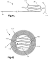
- FIG. 5A and 5B Another example is illustrated in Figs. 5A and 5B .
- FIGs. 5A and 5B reference numbers similar to those used in Figs. 4A-4B will be utilized, the suffix letter "a" being associated with the numerals of Figs. 5A and 5B to avoid confusion.
- the embodiment of Figs. 5A and 5B is similar to the embodiment of Figs. 4A-4B , except that the Z-fold 110 of Figs. 4A and 4B is replaced with a flip-fold in Figs. 5A-5B .
- the lower edge portion 38a of the inflatable curtain 14a is initially folded over once in a manner referred to herein as a flip-fold.
- the flip-fold 130 is illustrated in Fig. 5A .
- the inflatable curtain 14a is then rolled, beginning with the flip-fold 130 and the lower edge portion 38a, in the direction indicated generally at arrow 112a in Fig. 5A .
- the rolling is continued until the inflatable curtain 14a achieves the completely rolled-up condition illustrated in Fig. 5B .
- the roll 114a illustrated in Fig. 5B leaves a central space 116a in which the flip-fold 130 portion of the curtain 14a is positioned.
- the flip-fold 130 includes a single fold 132. Nevertheless, this single fold 132 and the resulting flip fold 130 being positioned in the central space 116a can produce a significant reduction in package space. This is due at least in part to the fact that the flip-fold 130 is made in the lower edge portion 38a of the inflatable curtain 14a.
- the lower edge portion 38a can include stitching that interconnects the overlying panels of the curtain 14a, any sealing materials (e.g., coatings or gaskets) used to seal the stitching and/or edge of the curtain, and reinforcing materials, all of which can make it difficult to roll that particular portion of the curtain.
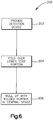
- a method 200 for placing the inflatable curtain in a stored condition includes the step 202 providing an inflatable vehicle occupant protection device having an upper edge portion for being connected to the vehicle along the vehicle roof and an opposite lower edge portion.
- the method 200 also includes the step 204 of folding the lower edge portion over onto itself at least once.
- the method 200 further includes the step 206 of rolling the protection device up such that the folded over lower edge portion occupies a central space surrounded by the rolled up portion.
- the step 206 of rolling the protection device comprises the step of maintaining the folded over lower edge portion positioned in the central space so that it does not become rolled up with the remainder of the protection device.
- the step 204 of folding the lower edge portion can include folding the lower edge portion in a Z-fold configuration.
- the Z-fold configuration can include at least two folds in opposite directions.
- the step 204 of folding the lower edge portion can include folding the lower edge portion in a single fold configuration.
- the single fold configuration can include a single folded portion that occupies multiple layers of the roll.
Description
- The invention relates to an inflatable vehicle occupant protection device according to the preamble of claim 2 for helping to protect an occupant of a vehicle and to a method for placing an inflatable vehicle occupant protection device in a stored condition according to the preamble of claim 1.
- It is known to inflate an inflatable vehicle occupant protection device to help protect a vehicle occupant upon the occurrence of an event for which occupant protection is desired, such as a vehicle collision or rollover. One particular type of inflatable vehicle occupant protection device is an inflatable curtain. Inflatable curtains are inflatable from a stored condition away from a vehicle roof to a deployed position between a side structure of the vehicle and a vehicle occupant.
- Generic
US 2010/0007121 A1 shows an inflatable curtain that is partially rolled up from its lower end. -
US 6,361,068 B1 shows an inflatable curtain the lower edge portion of which is folded back onto its upper edge portion and the curtain is rolled up from the folding line. -
US 2007/0205589 A1 shows a rolled-up inflatable protection device according to the preamble of claims 1 and 2. - The invention relates to an apparatus for helping to protect an occupant of a vehicle having the features of claim 2.
- The invention also relates to a method for helping to protect an occupant of a vehicle with the features of claim 1.
- The foregoing and other features of the invention will become apparent to those skilled in the art to which the invention relates upon reading the following description with reference to the accompanying drawings, in which:
-
Fig. 1 is a schematic view illustrating a stored condition of an apparatus for helping to protect an occupant of a vehicle, according to the invention. -
Fig. 2 is a schematic view illustrating a deployed condition of the apparatus ofFig. 1 . -
Fig. 3A is a plan view of a cover portion of the apparatus. -
Fig. 3B is an isometric view of the cover ofFig. 3A in an assembled condition. -
Figs. 4A and 4B are schematic views illustrating a portion of the apparatus according to a first embodiment of the invention. -
Figs. 5A and 5B are schematic views illustrating a portion of the apparatus according to a second example. -
Fig. 6 is a block diagram illustrating a method according to the invention. - Representative of the invention,
Figs. 1 and 2 illustrate anapparatus 10 for helping to protectoccupants 28 of avehicle 12. Theapparatus 10 includes an inflatable vehicle occupant protection device in the form of aninflatable curtain 14. Theinflatable curtain 14 has a stored condition, shown inFig. 1 , in which the deflated curtain is rolled, folded, or rolled and folded, and positioned adjacent the intersection of aside structure 16 and aroof 18 of thevehicle 12. Theinflatable curtain 14 is inflatable from the stored position in a direction away from theroof 18 to a deployed position shown inFig. 2 . In the deployed position, the inflatedcurtain 14 extends along theside structure 16 and is positioned between the side structure and anyoccupants 28 of thevehicle 12. - The
inflatable curtain 14 can be formed from any suitable material. For example, theinflatable curtain 14 may be formed from a fabric woven with nylon yarns (e.g., nylon 6-6 yarns). Also, theinflatable curtain 14 may have any suitable construction. For example, theinflatable curtain 14 may have a one piece woven (OPW) construction in which the curtain is woven as a single piece of material. As another example, theinflatable curtain 14 may be constructed by interconnecting fabric panels via means, such as stitching, ultrasonic welding, heat bonding, or adhesives. - The
inflatable curtain 14 may be uncoated, coated with a material, such as a gas impermeable urethane, or laminated with a material, such as a gas impermeable film. Theinflatable curtain 14 thus may have a gas-tight or substantially gas-tight construction. Those skilled in the art will appreciate that alternative materials, such as polyester yarn, and alternatives coatings, such as silicone, may also be used to construct theinflatable curtain 14. - The
apparatus 10 also includes an inflation fluid source in the form of aninflater 24. Theinflator 24 is actuatable to provide inflation fluid for inflating theinflatable curtain 14. Theinflater 24 may be of any suitable construction or configuration. For example, theinflator 24 may contain a stored quantity of pressurized inflation fluid (not shown) in the form of a gas for inflating theinflatable curtain 14. As another example, theinflator 24 could contain a combination of pressurized inflation fluid and ignitable material for heating the inflation fluid, or could be a pyrotechnic inflator that uses the combustion of gas-generating material to generate inflation fluid. As a further example, theinflater 24 could be of any suitable type or construction for supplying a medium for providing inflation fluid for inflating theinflatable curtain 14. - In the embodiment illustrated in
Fig. 1 , theinflater 24 is connected in fluid communication with theinflatable curtain 14 through a conduit orfill tube 22. Thefill tube 22 may be constructed of any suitable material, such as metal, plastic, or fabric. Alternatively, thefill tube 22 may be omitted and inflation fluid could be discharged into theinflatable curtain 14 from theinflater 24 directly or through a manifold. - The
fill tube 22 may also have any suitable configuration. For example, thefill tube 22 may extend substantially along the entire length of theinflatable curtain 14, as shown inFigs. 1 and 2 . Alternatively, thefill tube 22 may extend along any portion of the length of theinflatable curtain 14. The portion of thefill tube 22 positioned in theinflatable curtain 14 includes a plurality of openings (not shown) through which inflation fluid is delivered to the curtain. - The
apparatus 10 also includes acover 44 that helps support theinflatable curtain 14 in the stored condition. Thecover 44 may have various constructions. For example, thecover 44 may have what is referred to as a "soft pack" construction. In a soft pack construction, thecover 44 may comprise a sheet or panel of material, such as fabric, that is wrapped or otherwise placed around theinflatable curtain 14. In one particular soft pack construction, thecover 44 is configured as a sock, sheath, or tube into which theinflatable curtain 14 andfill tube 22 are placed. - The fabric material used to construct the
cover 44 may be a woven material, such as nylon or polyester, a non-woven material, such as a plastic film, or any other suitable material. Thecover 44 may be constructed by interconnecting portions of the fabric material using known means, such as an adhesive, stitching, ultrasonic welding, heat bonding, or weaving the cover with an OPW construction. In one particular soft pack construction, thecover 44 may be formed by interconnecting portions of the fabric material via ultrasonic welding. Such a construction is shown inFigs. 3A and 3B . - Referring to
Figs. 3A and 3B , thecover 44 may comprise apanel 80 of material that includesopenings 92 cut or otherwise formed along afirst edge portion 86 of the panel. Theopenings 92 may have any desired configuration, such as the generally rectangular notched configuration shown inFigs. 3A and 3B . Theopenings 92 may intersect thelower edge 86 of thepanel 80 as shown inFigs. 3A and 3B . Alternatively, theopenings 92 may be spaced from thelower edge 86 of thepanel 80. In an assembled condition of thecover 44, shown inFig. 3B , thefirst edge portion 86 is interconnected with an oppositesecond edge portion 88 by anultrasonic weld 84. This gives the cover 44 a generally tubular sock or sheath-like configuration. - The
cover 44 also includes alongitudinal tear seam 126 that extends generally parallel to the first andsecond edge portions cover 44. As shown inFigs. 3A and 3B , thetear seam 126 may be positioned generally centrally between the first andsecond edge portions 86 and 88 (Fig. 3A ) and opposite the ultrasonic weld 84 (Fig. 3B ). Thetear seam 126 may, for example, comprise perforations that weaken the tear strength of thepanel 80 along the tear seam. - The
apparatus 10 may be assembled for installation in thevehicle 12 as a unit. For example, theapparatus 10 may comprise an inflatable curtain module 50 (Fig. 4 ) that includes theinflater 24 connected to thefill tube 22, which is positioned in the rolled or foldedinflatable curtain 14 and packaged in thecover 44. Theinflatable curtain module 50 is supported in thevehicle 12 bymeans 30, such as hooks or brackets, that connect theinflatable curtain 14,inflator 24, filltube 22,cover 44, or any combination thereof, to thevehicle 12. For example, thebrackets 30 may encircle and clamp onto thefill tube 22 and portions of anupper edge portion 30 of theinflatable curtain 14 and extend through theopenings 92 in thecover 44, - Upon sensing the occurrence of an event for which inflation of the
inflatable curtain 14 is desired, asensor 150 provides an actuation signal to the inflator 24 vialead wires 152. Upon actuation of theinflater 24, inflation fluid is directed through thefill tube 22 into theinflatable curtain 14. The inflatingcurtain 14 ruptures thecover 44 along thetear seam 126. Theinflatable curtain 14 inflates and deploys under the pressure of inflation fluid provided by theinflater 24 from the stored position ofFig. 1 to the deployed position ofFig. 2 . - In the deployed position, the
inflatable curtain 14 is positioned between theside structure 16 and anyoccupants 28 of thevehicle 12. Theinflatable curtain 14, when inflated, extends fore and aft in thevehicle 12 along theside structure 16 and may cover portions of anA pillar 100,B pillar 102 and aC pillar 104 of the vehicle. Theupper edge portion 30 extends along the intersection of theside structure 16 and thevehicle roof 18, and alower edge portion 38 extends along the side structure adjacent or near a vehicle belt line. Theinflatable curtain 14 helps absorb impacts with the curtain and helps distribute the energy of impacts throughout a large area of the curtain. - In the tight confines of the vehicle structure along the
side structure 16 androof 18, space can be limited. As such, it can be highly desirable that the size of the inflatable curtain module 50 (referred to herein as "package size") be kept at a minimum. In this space, with space at such a premium, space savings even in the range of millimeters can be of great significance because the savings can be the determining factor on whether a particular curtain configuration can be used in a vehicle having a particular roof/side structure architecture. - One manner of placing the
inflatable curtain 14 in the stored condition is using what is referred to as a roll-fold in which the curtain is rolled from the bottom up. When placing theinflatable curtain 14 in the stored condition in this manner, it is be desirable to maintain a tight roll, tight fold, or tight roll to help minimize the roll diameter of the curtain. Even so, when doing so, there are physical limitations placed by factors such as the material used to construct theinflatable curtain 14 and any applied coatings. For example, rolling theinflatable curtain 14 overly tight could cause blocking, in which overlying portions of the air bag stick to one another or otherwise resist or inhibit unrolling, which can inhibit quick and efficient curtain deployment. Additionally, the materials used to construct the material can inhibit the ability to roll the curtain to an ideally small diameter that reduces the package size of theinflatable curtain module 50. For example, the materials used to construct the inflatable curtain, the coatings applied to the curtain panels, and the materials used to interconnect the curtain panels can affect how tightly the curtain can be rolled, i.e., how small the diameter of the initial rolls of the curtain can be. - According to the invention, the
inflatable curtain 14 employs a folding and rolling technique that is configured to take advantage of otherwise unused space in order to reduce the package size of theinflatable curtain module 50. Referring toFigs. 4A-4C , according to one example embodiment, theinflatable curtain 14 employs a Z-folded and rolled configuration that utilizes space in the center of the roll to reduce the overall package size of theinflatable curtain module 50. By initially folding thelower edge portion 38 and then rolling theinflatable curtain 14, the lower edge portion can be at least partially positioned in the otherwise unoccupied central space of the roll. By utilizing the otherwise unoccupied central space, the number of rolls in the curtain when in the stored condition can be reduced, which reduces the package size of the inflatable curtain module. - To achieve the reduced package size, the
lower edge portion 38 of theinflatable curtain 14 is initially folded in a back-and-forth manner referred to herein as a Z-fold. TheZ-fold 110 is illustrated inFig. 4A . Once theZ-fold 110 is established, theinflatable curtain 14 is then rolled, beginning with theZ-fold 110 and helower edge portion 38, in the direction indicated generally atarrow 112 inFig. 4A . The rolling is continued until theinflatable curtain 14 achieves the completely rolled-up condition illustrated inFig. 4B . Theroll 114 illustrated inFig. 4B leaves acentral space 116 in which theZ-fold 110 portion of thecurtain 14 is positioned. Since thisspace 116 would otherwise be left unoccupied, positioning theZ-fold 110 therein makes advantageous use of the central space. Using thecentral space 116 to store the Z-foldedportion 110 of theinflatable curtain 14 thus helps to reduce the package size of theinflatable curtain module 50. - When placing the
inflatable curtain 14 in theroll 114, care must be exercised to both maintain the folded condition of theZ-fold 110 and to maintain the position of the Z-fold in thecentral space 116. If such care is not exercised, the Z-fold 110 can become flattened and rolled up along with theroll 114. If this occurs, then theZ-fold 110 becomes part of theroll 114 instead of occupying thecentral space 116. The resultingroll 114 would not be reduced in size and may, in fact, be increased in size due to theZ-fold 110 being the initially rolled-up portion of thecurtain 14. - In the embodiment illustrated in
Figs. 4A and 4B , theZ-fold 110 includes seven folds 120. TheZ-fold 110 could, however include a greater number of folds or fewer folds. The number of folds included in theZ-fold 110 depends on interrelated factors such as the material used to construct theinflatable curtain 14, the types of coatings or laminated used on the curtains, reinforcements at thelower edge portion 38, and any stitching/adhesives used to interconnect the overlying curtain panels along the lower edge portion. Ideally, portions of thecurtain 14 that limit the ability to roll thelower edge portion 38, can be included in theZ-fold 110 so as not to impact the diameter of theroll 114. For example, stitching and accompanying sealing of the stitching along thelower edge portion 38 may not be conducive to rolling thecurtain 14. By including these portions in theZ-fold 110, however, these portions can be positioned in thecentral space 116. As a result, not only is the diameter of theroll 114 not increased by the stitching, it can in fact be decreased by placing that portion of thecurtain 14 in theZ-fold 110 and positioned in the central space. - Another example is illustrated in
Figs. 5A and 5B . InFigs. 5A and 5B , reference numbers similar to those used inFigs. 4A-4B will be utilized, the suffix letter "a" being associated with the numerals ofFigs. 5A and 5B to avoid confusion. The embodiment ofFigs. 5A and 5B is similar to the embodiment ofFigs. 4A-4B , except that theZ-fold 110 ofFigs. 4A and 4B is replaced with a flip-fold inFigs. 5A-5B . - In the example of
Figs. 5A and 5B , thelower edge portion 38a of theinflatable curtain 14a is initially folded over once in a manner referred to herein as a flip-fold. The flip-fold 130 is illustrated inFig. 5A . Once the flip-fold 130 is established, theinflatable curtain 14a is then rolled, beginning with the flip-fold 130 and thelower edge portion 38a, in the direction indicated generally atarrow 112a inFig. 5A . The rolling is continued until theinflatable curtain 14a achieves the completely rolled-up condition illustrated inFig. 5B . The roll 114a illustrated inFig. 5B leaves acentral space 116a in which the flip-fold 130 portion of thecurtain 14a is positioned. Since thisspace 116a would otherwise be left unoccupied, positioning the flip-fold 130 therein makes advantageous use of the central space. Using thecentral space 116a to store the flip-foldedportion 130 of theinflatable curtain 14a thus helps to reduce the package size of the inflatable curtain module. - When placing the
inflatable curtain 14a in the roll 114a, care must be exercised to both maintain the folded condition of the flip-fold 130 and to maintain the position of the flip-fold in thecentral space 116a. If such care is not exercised, the flip-fold 130 can become flattened and rolled up along with the roll 114a. If this occurs, then the flip-fold 130 becomes part of the roll 114a instead of occupying thecentral space 116a. The resulting roll 114a would not be reduced in size and may, in fact, be increased in size due to the flip-fold 130 being the initially rolled-up portion of thecurtain 14a. - In the example illustrated in
Figs. 5A and 5B , the flip-fold 130 includes asingle fold 132. Nevertheless, thissingle fold 132 and the resulting flip fold 130 being positioned in thecentral space 116a can produce a significant reduction in package space. This is due at least in part to the fact that the flip-fold 130 is made in thelower edge portion 38a of theinflatable curtain 14a. Thelower edge portion 38a can include stitching that interconnects the overlying panels of thecurtain 14a, any sealing materials (e.g., coatings or gaskets) used to seal the stitching and/or edge of the curtain, and reinforcing materials, all of which can make it difficult to roll that particular portion of the curtain. As a result, rolling thislower portion 38a of thecurtain 14a can require the initial rolls to have a larger than desired diameter which cascades throughout the rolling of the curtain, leading to a package size that is larger than desired. Placing the flip-fold 130 in thecentral space 116a at least partially removes thelower portion 38a of thecurtain 14a from impacting the diameter of the roll 114a, thereby reducing the package size of the inflatable curtain module. - Referring to
Fig. 6 , amethod 200 for placing the inflatable curtain in a stored condition includes thestep 202 providing an inflatable vehicle occupant protection device having an upper edge portion for being connected to the vehicle along the vehicle roof and an opposite lower edge portion. Themethod 200 also includes thestep 204 of folding the lower edge portion over onto itself at least once. Themethod 200 further includes thestep 206 of rolling the protection device up such that the folded over lower edge portion occupies a central space surrounded by the rolled up portion. Thestep 206 of rolling the protection device comprises the step of maintaining the folded over lower edge portion positioned in the central space so that it does not become rolled up with the remainder of the protection device. - The
step 204 of folding the lower edge portion can include folding the lower edge portion in a Z-fold configuration. The Z-fold configuration can include at least two folds in opposite directions. Alternatively, thestep 204 of folding the lower edge portion can include folding the lower edge portion in a single fold configuration. The single fold configuration can include a single folded portion that occupies multiple layers of the roll. - From the above description of the invention, those skilled in the art will perceive applications, improvements, changes and modifications to the invention. Such applications, improvements, changes and modifications within the skill of the art are intended to be covered by the appended claims.
Claims (2)
- A method for placing an Inflatable vehicle occupant protection device in a stored condition, the method comprising:providing an inflatable vehicle occupant protection device having an upper edge portion for being connected to the vehicle along the vehicle roof and an opposite lower edge portion (38) and rolling the protection device up,characterized by the steps of:
folding the lower edge portion (38) over onto itself in a Z-fold configuration (110) comprising at least two folds in opposite directions; and rolling the protection device up such that the folded over lower edge portion (38) occupies a central space (116) surrounded by the rolled up portion, wherein the step of rolling the protection device comprises the step of maintaining the folded over lower edge portion positioned in the central space (116) so that it does not become flattened and rolled up with the remainder of the protection device. - An apparatus for helping to protect an occupant of a vehicle that has a side structure and a roof, the apparatus comprising:
an inflatable vehicle occupant protection device having a stored condition for being positioned along the vehicle roof, the protection device being inflatable away from the vehicle roof to a deployed condition positioned between the side structure and a vehicle occupant, the protection device comprising:
an upper edge portion for being connected to the vehicle along the vehicle roof and an opposite lower edge portion (38), characterized in that the lower edge portion (38) is folded over onto itself in a Z-fold configuration (110) comprising at least two folds in opposite directions in the stored condition of the protection device and the protection device when in the stored condition having a rolled-up configuration such that the folded over lower edge portion (38) occupies a central space (116) bounded by the rolled-up portion of the protection device, wherein the folded over lower edge portion (38) is maintained positioned in the central space (116) so that it is not flattened and rolled up with the remainder of the protection device.
Applications Claiming Priority (1)
| Application Number | Priority Date | Filing Date | Title |
|---|---|---|---|
| PCT/IB2013/000881 WO2014140665A1 (en) | 2013-03-13 | 2013-03-13 | Inflatable curtain and method for placing an inflatable curtain in a stored condition |
Publications (2)
| Publication Number | Publication Date |
|---|---|
| EP2969663A1 EP2969663A1 (en) | 2016-01-20 |
| EP2969663B1 true EP2969663B1 (en) | 2018-08-22 |
Family
ID=48628735
Family Applications (1)
| Application Number | Title | Priority Date | Filing Date |
|---|---|---|---|
| EP13729414.6A Active EP2969663B1 (en) | 2013-03-13 | 2013-03-13 | Inflatable curtain and method for placing an inflatable curtain in a stored condition |
Country Status (6)
| Country | Link |
|---|---|
| US (1) | US9623828B2 (en) |
| EP (1) | EP2969663B1 (en) |
| JP (1) | JP6335937B2 (en) |
| KR (1) | KR101942519B1 (en) |
| CN (1) | CN105209301B (en) |
| WO (1) | WO2014140665A1 (en) |
Families Citing this family (4)
| Publication number | Priority date | Publication date | Assignee | Title |
|---|---|---|---|---|
| WO2015028780A1 (en) * | 2013-08-28 | 2015-03-05 | Autoliv Development Ab | A method of packaging an air-bag |
| CN107235028B (en) * | 2016-03-29 | 2021-10-01 | 奥托立夫开发公司 | Airbag and airbag module |
| US10872281B2 (en) | 2018-10-18 | 2020-12-22 | Trw Vehicle Safety Systems Inc. | Airbag with bar code |
| US11648827B2 (en) * | 2019-12-10 | 2023-05-16 | GM Global Technology Operations LLC | Pneumatic shade |
Citations (1)
| Publication number | Priority date | Publication date | Assignee | Title |
|---|---|---|---|---|
| US20100007121A1 (en) * | 2008-07-11 | 2010-01-14 | Tk Holdings Inc. | Side curtain airbag |
Family Cites Families (15)
| Publication number | Priority date | Publication date | Assignee | Title |
|---|---|---|---|---|
| US6371512B1 (en) * | 1998-08-03 | 2002-04-16 | Toyota Jidosha Kabushiki Kaisha | Airbag apparatus for head-protecting |
| US6361068B1 (en) | 2000-05-23 | 2002-03-26 | Trw Vehicle Safety Systems Inc. | Folded inflatable side curtain with tether |
| JP3925226B2 (en) * | 2002-02-12 | 2007-06-06 | タカタ株式会社 | Curtain airbag and curtain airbag device |
| US7296822B2 (en) * | 2002-11-22 | 2007-11-20 | Trw Vehicle Safety Systems Inc. | Inflatable windshield curtain |
| US6899350B2 (en) * | 2003-01-07 | 2005-05-31 | Trw Vehicle Safety Systems Inc. | Inflatable curtain |
| US7731224B2 (en) | 2006-03-01 | 2010-06-08 | Trw Vehicle Safety Systems Inc. | Inflatable curtain |
| US8002310B2 (en) * | 2007-04-23 | 2011-08-23 | Trw Vehicle Safety System Inc. | Method and apparatus for placing an inflatable curtain in a stored condition |
| JP5429974B2 (en) * | 2009-09-30 | 2014-02-26 | 日本プラスト株式会社 | Air bag and air bag device |
| JP5366774B2 (en) * | 2009-11-27 | 2013-12-11 | 日本プラスト株式会社 | Air bag and air bag folding method |
| KR101659851B1 (en) * | 2013-02-28 | 2016-09-26 | 도요타 지도샤(주) | Head-protecting airbag device and method of folding airbag thereof |
| US10214173B2 (en) * | 2013-02-28 | 2019-02-26 | Autoliv Development Ab | Curtain airbag |
| DE102013008467B4 (en) * | 2013-05-21 | 2017-03-23 | Trw Automotive Gmbh | Fastening device for a folded airbag |
| DE102013011154B4 (en) * | 2013-07-04 | 2023-07-06 | Zf Automotive Germany Gmbh | Method for folding a side airbag and side airbag |
| JP6131827B2 (en) * | 2013-10-30 | 2017-05-24 | 豊田合成株式会社 | Head protection airbag device |
| DE102014212238B4 (en) * | 2014-06-25 | 2019-07-18 | Joyson Safety Systems Germany Gmbh | A gas bag for a vehicle occupant restraint system and method for folding a gas bag for a vehicle occupant restraint system |
-
2013
- 2013-03-13 CN CN201380076509.8A patent/CN105209301B/en active Active
- 2013-03-13 WO PCT/IB2013/000881 patent/WO2014140665A1/en active Application Filing
- 2013-03-13 US US14/774,793 patent/US9623828B2/en active Active
- 2013-03-13 KR KR1020157029076A patent/KR101942519B1/en active IP Right Grant
- 2013-03-13 EP EP13729414.6A patent/EP2969663B1/en active Active
- 2013-03-13 JP JP2015562342A patent/JP6335937B2/en active Active
Patent Citations (1)
| Publication number | Priority date | Publication date | Assignee | Title |
|---|---|---|---|---|
| US20100007121A1 (en) * | 2008-07-11 | 2010-01-14 | Tk Holdings Inc. | Side curtain airbag |
Also Published As
| Publication number | Publication date |
|---|---|
| CN105209301B (en) | 2017-09-01 |
| JP6335937B2 (en) | 2018-05-30 |
| KR20150143483A (en) | 2015-12-23 |
| KR101942519B1 (en) | 2019-01-28 |
| JP2016509973A (en) | 2016-04-04 |
| US20160031403A1 (en) | 2016-02-04 |
| WO2014140665A1 (en) | 2014-09-18 |
| CN105209301A (en) | 2015-12-30 |
| EP2969663A1 (en) | 2016-01-20 |
| US9623828B2 (en) | 2017-04-18 |
Similar Documents
| Publication | Publication Date | Title |
|---|---|---|
| US7731224B2 (en) | Inflatable curtain | |
| US6361068B1 (en) | Folded inflatable side curtain with tether | |
| US6471240B2 (en) | Inflatable side curtain | |
| US7516978B2 (en) | Anti-telescoping inflatable curtain | |
| US7513523B2 (en) | Inflatable curtain with different size panels | |
| EP2475555B1 (en) | Mounting assemblies with wrappers for inflatable curtain airbags | |
| US6565118B2 (en) | Folded inflatable curtain | |
| US20050206140A1 (en) | Inflatable curtain | |
| US8002310B2 (en) | Method and apparatus for placing an inflatable curtain in a stored condition | |
| JP5003631B2 (en) | Side airbag device | |
| US7000944B2 (en) | Inflatable windshield curtain | |
| US7185913B2 (en) | Inflatable windshield curtain | |
| US6428037B1 (en) | Inflatable curtain | |
| US20200276954A1 (en) | Vehicle occupant restraint system having an airbag module and method for assembling | |
| EP2969663B1 (en) | Inflatable curtain and method for placing an inflatable curtain in a stored condition | |
| US7296822B2 (en) | Inflatable windshield curtain | |
| US6793239B2 (en) | Inflatable vehicle occupant protection device for a vehicle with third row seating | |
| US10872281B2 (en) | Airbag with bar code | |
| US7562901B2 (en) | Inflatable curtain module with push-in fastener | |
| US11608021B2 (en) | Curtain airbag module with deployment ramp and bag wrap retention features | |
| JP2017087864A (en) | Head protection airbag |
Legal Events
| Date | Code | Title | Description |
|---|---|---|---|
| PUAI | Public reference made under article 153(3) epc to a published international application that has entered the european phase |
Free format text: ORIGINAL CODE: 0009012 |
|
| 17P | Request for examination filed |
Effective date: 20151013 |
|
| AK | Designated contracting states |
Kind code of ref document: A1 Designated state(s): AL AT BE BG CH CY CZ DE DK EE ES FI FR GB GR HR HU IE IS IT LI LT LU LV MC MK MT NL NO PL PT RO RS SE SI SK SM TR |
|
| AX | Request for extension of the european patent |
Extension state: BA ME |
|
| RIN1 | Information on inventor provided before grant (corrected) |
Inventor name: NAYEF, EYAD Inventor name: YIN, LIANG Inventor name: EMAMBAKHSH, ALI |
|
| RIN1 | Information on inventor provided before grant (corrected) |
Inventor name: YIN, LIANG Inventor name: NAYEF, EYAD Inventor name: EMAMBAKHSH, ALI |
|
| DAX | Request for extension of the european patent (deleted) | ||
| STAA | Information on the status of an ep patent application or granted ep patent |
Free format text: STATUS: EXAMINATION IS IN PROGRESS |
|
| 17Q | First examination report despatched |
Effective date: 20170502 |
|
| GRAP | Despatch of communication of intention to grant a patent |
Free format text: ORIGINAL CODE: EPIDOSNIGR1 |
|
| STAA | Information on the status of an ep patent application or granted ep patent |
Free format text: STATUS: GRANT OF PATENT IS INTENDED |
|
| INTG | Intention to grant announced |
Effective date: 20180314 |
|
| GRAS | Grant fee paid |
Free format text: ORIGINAL CODE: EPIDOSNIGR3 |
|
| GRAA | (expected) grant |
Free format text: ORIGINAL CODE: 0009210 |
|
| STAA | Information on the status of an ep patent application or granted ep patent |
Free format text: STATUS: THE PATENT HAS BEEN GRANTED |
|
| AK | Designated contracting states |
Kind code of ref document: B1 Designated state(s): AL AT BE BG CH CY CZ DE DK EE ES FI FR GB GR HR HU IE IS IT LI LT LU LV MC MK MT NL NO PL PT RO RS SE SI SK SM TR |
|
| REG | Reference to a national code |
Ref country code: GB Ref legal event code: FG4D |
|
| REG | Reference to a national code |
Ref country code: CH Ref legal event code: EP |
|
| REG | Reference to a national code |
Ref country code: AT Ref legal event code: REF Ref document number: 1032079 Country of ref document: AT Kind code of ref document: T Effective date: 20180915 |
|
| REG | Reference to a national code |
Ref country code: IE Ref legal event code: FG4D |
|
| REG | Reference to a national code |
Ref country code: DE Ref legal event code: R096 Ref document number: 602013042373 Country of ref document: DE |
|
| REG | Reference to a national code |
Ref country code: NL Ref legal event code: MP Effective date: 20180822 |
|
| REG | Reference to a national code |
Ref country code: LT Ref legal event code: MG4D |
|
| PG25 | Lapsed in a contracting state [announced via postgrant information from national office to epo] |
Ref country code: GR Free format text: LAPSE BECAUSE OF FAILURE TO SUBMIT A TRANSLATION OF THE DESCRIPTION OR TO PAY THE FEE WITHIN THE PRESCRIBED TIME-LIMIT Effective date: 20181123 Ref country code: NO Free format text: LAPSE BECAUSE OF FAILURE TO SUBMIT A TRANSLATION OF THE DESCRIPTION OR TO PAY THE FEE WITHIN THE PRESCRIBED TIME-LIMIT Effective date: 20181122 Ref country code: RS Free format text: LAPSE BECAUSE OF FAILURE TO SUBMIT A TRANSLATION OF THE DESCRIPTION OR TO PAY THE FEE WITHIN THE PRESCRIBED TIME-LIMIT Effective date: 20180822 Ref country code: SE Free format text: LAPSE BECAUSE OF FAILURE TO SUBMIT A TRANSLATION OF THE DESCRIPTION OR TO PAY THE FEE WITHIN THE PRESCRIBED TIME-LIMIT Effective date: 20180822 Ref country code: FI Free format text: LAPSE BECAUSE OF FAILURE TO SUBMIT A TRANSLATION OF THE DESCRIPTION OR TO PAY THE FEE WITHIN THE PRESCRIBED TIME-LIMIT Effective date: 20180822 Ref country code: IS Free format text: LAPSE BECAUSE OF FAILURE TO SUBMIT A TRANSLATION OF THE DESCRIPTION OR TO PAY THE FEE WITHIN THE PRESCRIBED TIME-LIMIT Effective date: 20181222 Ref country code: LT Free format text: LAPSE BECAUSE OF FAILURE TO SUBMIT A TRANSLATION OF THE DESCRIPTION OR TO PAY THE FEE WITHIN THE PRESCRIBED TIME-LIMIT Effective date: 20180822 Ref country code: BG Free format text: LAPSE BECAUSE OF FAILURE TO SUBMIT A TRANSLATION OF THE DESCRIPTION OR TO PAY THE FEE WITHIN THE PRESCRIBED TIME-LIMIT Effective date: 20181122 Ref country code: NL Free format text: LAPSE BECAUSE OF FAILURE TO SUBMIT A TRANSLATION OF THE DESCRIPTION OR TO PAY THE FEE WITHIN THE PRESCRIBED TIME-LIMIT Effective date: 20180822 |
|
| REG | Reference to a national code |
Ref country code: AT Ref legal event code: MK05 Ref document number: 1032079 Country of ref document: AT Kind code of ref document: T Effective date: 20180822 |
|
| PG25 | Lapsed in a contracting state [announced via postgrant information from national office to epo] |
Ref country code: LV Free format text: LAPSE BECAUSE OF FAILURE TO SUBMIT A TRANSLATION OF THE DESCRIPTION OR TO PAY THE FEE WITHIN THE PRESCRIBED TIME-LIMIT Effective date: 20180822 Ref country code: AL Free format text: LAPSE BECAUSE OF FAILURE TO SUBMIT A TRANSLATION OF THE DESCRIPTION OR TO PAY THE FEE WITHIN THE PRESCRIBED TIME-LIMIT Effective date: 20180822 Ref country code: HR Free format text: LAPSE BECAUSE OF FAILURE TO SUBMIT A TRANSLATION OF THE DESCRIPTION OR TO PAY THE FEE WITHIN THE PRESCRIBED TIME-LIMIT Effective date: 20180822 |
|
| PG25 | Lapsed in a contracting state [announced via postgrant information from national office to epo] |
Ref country code: EE Free format text: LAPSE BECAUSE OF FAILURE TO SUBMIT A TRANSLATION OF THE DESCRIPTION OR TO PAY THE FEE WITHIN THE PRESCRIBED TIME-LIMIT Effective date: 20180822 Ref country code: PL Free format text: LAPSE BECAUSE OF FAILURE TO SUBMIT A TRANSLATION OF THE DESCRIPTION OR TO PAY THE FEE WITHIN THE PRESCRIBED TIME-LIMIT Effective date: 20180822 Ref country code: IT Free format text: LAPSE BECAUSE OF FAILURE TO SUBMIT A TRANSLATION OF THE DESCRIPTION OR TO PAY THE FEE WITHIN THE PRESCRIBED TIME-LIMIT Effective date: 20180822 Ref country code: RO Free format text: LAPSE BECAUSE OF FAILURE TO SUBMIT A TRANSLATION OF THE DESCRIPTION OR TO PAY THE FEE WITHIN THE PRESCRIBED TIME-LIMIT Effective date: 20180822 Ref country code: AT Free format text: LAPSE BECAUSE OF FAILURE TO SUBMIT A TRANSLATION OF THE DESCRIPTION OR TO PAY THE FEE WITHIN THE PRESCRIBED TIME-LIMIT Effective date: 20180822 Ref country code: CZ Free format text: LAPSE BECAUSE OF FAILURE TO SUBMIT A TRANSLATION OF THE DESCRIPTION OR TO PAY THE FEE WITHIN THE PRESCRIBED TIME-LIMIT Effective date: 20180822 Ref country code: ES Free format text: LAPSE BECAUSE OF FAILURE TO SUBMIT A TRANSLATION OF THE DESCRIPTION OR TO PAY THE FEE WITHIN THE PRESCRIBED TIME-LIMIT Effective date: 20180822 |
|
| REG | Reference to a national code |
Ref country code: DE Ref legal event code: R097 Ref document number: 602013042373 Country of ref document: DE |
|
| PG25 | Lapsed in a contracting state [announced via postgrant information from national office to epo] |
Ref country code: SK Free format text: LAPSE BECAUSE OF FAILURE TO SUBMIT A TRANSLATION OF THE DESCRIPTION OR TO PAY THE FEE WITHIN THE PRESCRIBED TIME-LIMIT Effective date: 20180822 Ref country code: DK Free format text: LAPSE BECAUSE OF FAILURE TO SUBMIT A TRANSLATION OF THE DESCRIPTION OR TO PAY THE FEE WITHIN THE PRESCRIBED TIME-LIMIT Effective date: 20180822 Ref country code: SM Free format text: LAPSE BECAUSE OF FAILURE TO SUBMIT A TRANSLATION OF THE DESCRIPTION OR TO PAY THE FEE WITHIN THE PRESCRIBED TIME-LIMIT Effective date: 20180822 |
|
| PLBE | No opposition filed within time limit |
Free format text: ORIGINAL CODE: 0009261 |
|
| STAA | Information on the status of an ep patent application or granted ep patent |
Free format text: STATUS: NO OPPOSITION FILED WITHIN TIME LIMIT |
|
| 26N | No opposition filed |
Effective date: 20190523 |
|
| PG25 | Lapsed in a contracting state [announced via postgrant information from national office to epo] |
Ref country code: SI Free format text: LAPSE BECAUSE OF FAILURE TO SUBMIT A TRANSLATION OF THE DESCRIPTION OR TO PAY THE FEE WITHIN THE PRESCRIBED TIME-LIMIT Effective date: 20180822 |
|
| PG25 | Lapsed in a contracting state [announced via postgrant information from national office to epo] |
Ref country code: MC Free format text: LAPSE BECAUSE OF FAILURE TO SUBMIT A TRANSLATION OF THE DESCRIPTION OR TO PAY THE FEE WITHIN THE PRESCRIBED TIME-LIMIT Effective date: 20180822 |
|
| REG | Reference to a national code |
Ref country code: CH Ref legal event code: PL |
|
| GBPC | Gb: european patent ceased through non-payment of renewal fee |
Effective date: 20190313 |
|
| PG25 | Lapsed in a contracting state [announced via postgrant information from national office to epo] |
Ref country code: LU Free format text: LAPSE BECAUSE OF NON-PAYMENT OF DUE FEES Effective date: 20190313 |
|
| REG | Reference to a national code |
Ref country code: BE Ref legal event code: MM Effective date: 20190331 |
|
| PG25 | Lapsed in a contracting state [announced via postgrant information from national office to epo] |
Ref country code: GB Free format text: LAPSE BECAUSE OF NON-PAYMENT OF DUE FEES Effective date: 20190313 Ref country code: LI Free format text: LAPSE BECAUSE OF NON-PAYMENT OF DUE FEES Effective date: 20190331 Ref country code: IE Free format text: LAPSE BECAUSE OF NON-PAYMENT OF DUE FEES Effective date: 20190313 Ref country code: CH Free format text: LAPSE BECAUSE OF NON-PAYMENT OF DUE FEES Effective date: 20190331 |
|
| PG25 | Lapsed in a contracting state [announced via postgrant information from national office to epo] |
Ref country code: BE Free format text: LAPSE BECAUSE OF NON-PAYMENT OF DUE FEES Effective date: 20190331 |
|
| PG25 | Lapsed in a contracting state [announced via postgrant information from national office to epo] |
Ref country code: TR Free format text: LAPSE BECAUSE OF FAILURE TO SUBMIT A TRANSLATION OF THE DESCRIPTION OR TO PAY THE FEE WITHIN THE PRESCRIBED TIME-LIMIT Effective date: 20180822 |
|
| PG25 | Lapsed in a contracting state [announced via postgrant information from national office to epo] |
Ref country code: PT Free format text: LAPSE BECAUSE OF FAILURE TO SUBMIT A TRANSLATION OF THE DESCRIPTION OR TO PAY THE FEE WITHIN THE PRESCRIBED TIME-LIMIT Effective date: 20181222 Ref country code: MT Free format text: LAPSE BECAUSE OF NON-PAYMENT OF DUE FEES Effective date: 20190313 |
|
| PGFP | Annual fee paid to national office [announced via postgrant information from national office to epo] |
Ref country code: FR Payment date: 20200325 Year of fee payment: 8 |
|
| REG | Reference to a national code |
Ref country code: DE Ref legal event code: R082 Ref document number: 602013042373 Country of ref document: DE Representative=s name: MEHNERT, BERNHARD, DE Ref country code: DE Ref legal event code: R081 Ref document number: 602013042373 Country of ref document: DE Owner name: ZF PASSIVE SAFETY SYSTEMS US INC., WASHINGTON, US Free format text: FORMER OWNER: TRW VEHICLE SAFETY SYSTEMS INC., WASHINGTON, MICH., US |
|
| PG25 | Lapsed in a contracting state [announced via postgrant information from national office to epo] |
Ref country code: CY Free format text: LAPSE BECAUSE OF FAILURE TO SUBMIT A TRANSLATION OF THE DESCRIPTION OR TO PAY THE FEE WITHIN THE PRESCRIBED TIME-LIMIT Effective date: 20180822 |
|
| PG25 | Lapsed in a contracting state [announced via postgrant information from national office to epo] |
Ref country code: HU Free format text: LAPSE BECAUSE OF FAILURE TO SUBMIT A TRANSLATION OF THE DESCRIPTION OR TO PAY THE FEE WITHIN THE PRESCRIBED TIME-LIMIT; INVALID AB INITIO Effective date: 20130313 |
|
| PG25 | Lapsed in a contracting state [announced via postgrant information from national office to epo] |
Ref country code: FR Free format text: LAPSE BECAUSE OF NON-PAYMENT OF DUE FEES Effective date: 20210331 |
|
| PG25 | Lapsed in a contracting state [announced via postgrant information from national office to epo] |
Ref country code: MK Free format text: LAPSE BECAUSE OF FAILURE TO SUBMIT A TRANSLATION OF THE DESCRIPTION OR TO PAY THE FEE WITHIN THE PRESCRIBED TIME-LIMIT Effective date: 20180822 |
|
| PGFP | Annual fee paid to national office [announced via postgrant information from national office to epo] |
Ref country code: DE Payment date: 20230331 Year of fee payment: 11 |
|
| P01 | Opt-out of the competence of the unified patent court (upc) registered |
Effective date: 20230602 |