EP2969554B1 - Flexible ceramic matrix composite seal assembled with gas turbine engine components - Google Patents
Flexible ceramic matrix composite seal assembled with gas turbine engine components Download PDFInfo
- Publication number
- EP2969554B1 EP2969554B1 EP14716670.6A EP14716670A EP2969554B1 EP 2969554 B1 EP2969554 B1 EP 2969554B1 EP 14716670 A EP14716670 A EP 14716670A EP 2969554 B1 EP2969554 B1 EP 2969554B1
- Authority
- EP
- European Patent Office
- Prior art keywords
- fabric
- plane
- portions
- ceramic matrix
- top fabric
- Prior art date
- Legal status (The legal status is an assumption and is not a legal conclusion. Google has not performed a legal analysis and makes no representation as to the accuracy of the status listed.)
- Active
Links
- 239000011153 ceramic matrix composite Substances 0.000 title claims description 42
- 239000004744 fabric Substances 0.000 claims description 262
- 239000000835 fiber Substances 0.000 claims description 105
- 239000000919 ceramic Substances 0.000 claims description 80
- 239000011159 matrix material Substances 0.000 claims description 41
- 230000002787 reinforcement Effects 0.000 claims description 14
- 238000000429 assembly Methods 0.000 claims description 10
- 230000000712 assembly Effects 0.000 claims description 10
- 230000000694 effects Effects 0.000 claims description 2
- 238000000576 coating method Methods 0.000 description 7
- 238000000034 method Methods 0.000 description 7
- HBMJWWWQQXIZIP-UHFFFAOYSA-N silicon carbide Chemical compound [Si+]#[C-] HBMJWWWQQXIZIP-UHFFFAOYSA-N 0.000 description 7
- PNEYBMLMFCGWSK-UHFFFAOYSA-N aluminium oxide Inorganic materials [O-2].[O-2].[O-2].[Al+3].[Al+3] PNEYBMLMFCGWSK-UHFFFAOYSA-N 0.000 description 6
- 239000011248 coating agent Substances 0.000 description 6
- 239000000463 material Substances 0.000 description 6
- 229910000323 aluminium silicate Inorganic materials 0.000 description 4
- HNPSIPDUKPIQMN-UHFFFAOYSA-N dioxosilane;oxo(oxoalumanyloxy)alumane Chemical compound O=[Si]=O.O=[Al]O[Al]=O HNPSIPDUKPIQMN-UHFFFAOYSA-N 0.000 description 4
- 238000001764 infiltration Methods 0.000 description 4
- 230000008595 infiltration Effects 0.000 description 4
- 238000007789 sealing Methods 0.000 description 4
- 229910010271 silicon carbide Inorganic materials 0.000 description 4
- 229910052580 B4C Inorganic materials 0.000 description 3
- OKTJSMMVPCPJKN-UHFFFAOYSA-N Carbon Chemical compound [C] OKTJSMMVPCPJKN-UHFFFAOYSA-N 0.000 description 3
- INAHAJYZKVIDIZ-UHFFFAOYSA-N boron carbide Chemical compound B12B3B4C32B41 INAHAJYZKVIDIZ-UHFFFAOYSA-N 0.000 description 3
- 229910052799 carbon Inorganic materials 0.000 description 3
- 239000000126 substance Substances 0.000 description 3
- 239000002131 composite material Substances 0.000 description 2
- 230000006835 compression Effects 0.000 description 2
- 238000007906 compression Methods 0.000 description 2
- 239000012466 permeate Substances 0.000 description 2
- 230000036316 preload Effects 0.000 description 2
- 229920000049 Carbon (fiber) Polymers 0.000 description 1
- XUIMIQQOPSSXEZ-UHFFFAOYSA-N Silicon Chemical compound [Si] XUIMIQQOPSSXEZ-UHFFFAOYSA-N 0.000 description 1
- 230000001154 acute effect Effects 0.000 description 1
- 239000004917 carbon fiber Substances 0.000 description 1
- 239000011204 carbon fibre-reinforced silicon carbide Substances 0.000 description 1
- 238000001816 cooling Methods 0.000 description 1
- 230000007613 environmental effect Effects 0.000 description 1
- 210000003746 feather Anatomy 0.000 description 1
- -1 for example Substances 0.000 description 1
- 239000003365 glass fiber Substances 0.000 description 1
- 238000004519 manufacturing process Methods 0.000 description 1
- 230000013011 mating Effects 0.000 description 1
- VNWKTOKETHGBQD-UHFFFAOYSA-N methane Chemical compound C VNWKTOKETHGBQD-UHFFFAOYSA-N 0.000 description 1
- 150000004767 nitrides Chemical class 0.000 description 1
- 239000011224 oxide ceramic Substances 0.000 description 1
- 229910052574 oxide ceramic Inorganic materials 0.000 description 1
- 239000004033 plastic Substances 0.000 description 1
- 229920000642 polymer Polymers 0.000 description 1
- 238000005381 potential energy Methods 0.000 description 1
- 230000001737 promoting effect Effects 0.000 description 1
- 229910052710 silicon Inorganic materials 0.000 description 1
- 239000010703 silicon Substances 0.000 description 1
- 238000004513 sizing Methods 0.000 description 1
Images

Classifications
-
- C—CHEMISTRY; METALLURGY
- C04—CEMENTS; CONCRETE; ARTIFICIAL STONE; CERAMICS; REFRACTORIES
- C04B—LIME, MAGNESIA; SLAG; CEMENTS; COMPOSITIONS THEREOF, e.g. MORTARS, CONCRETE OR LIKE BUILDING MATERIALS; ARTIFICIAL STONE; CERAMICS; REFRACTORIES; TREATMENT OF NATURAL STONE
- C04B35/00—Shaped ceramic products characterised by their composition; Ceramics compositions; Processing powders of inorganic compounds preparatory to the manufacturing of ceramic products
- C04B35/71—Ceramic products containing macroscopic reinforcing agents
- C04B35/78—Ceramic products containing macroscopic reinforcing agents containing non-metallic materials
- C04B35/80—Fibres, filaments, whiskers, platelets, or the like
-
- B—PERFORMING OPERATIONS; TRANSPORTING
- B32—LAYERED PRODUCTS
- B32B—LAYERED PRODUCTS, i.e. PRODUCTS BUILT-UP OF STRATA OF FLAT OR NON-FLAT, e.g. CELLULAR OR HONEYCOMB, FORM
- B32B18/00—Layered products essentially comprising ceramics, e.g. refractory products
-
- B—PERFORMING OPERATIONS; TRANSPORTING
- B32—LAYERED PRODUCTS
- B32B—LAYERED PRODUCTS, i.e. PRODUCTS BUILT-UP OF STRATA OF FLAT OR NON-FLAT, e.g. CELLULAR OR HONEYCOMB, FORM
- B32B5/00—Layered products characterised by the non- homogeneity or physical structure, i.e. comprising a fibrous, filamentary, particulate or foam layer; Layered products characterised by having a layer differing constitutionally or physically in different parts
- B32B5/22—Layered products characterised by the non- homogeneity or physical structure, i.e. comprising a fibrous, filamentary, particulate or foam layer; Layered products characterised by having a layer differing constitutionally or physically in different parts characterised by the presence of two or more layers which are next to each other and are fibrous, filamentary, formed of particles or foamed
- B32B5/24—Layered products characterised by the non- homogeneity or physical structure, i.e. comprising a fibrous, filamentary, particulate or foam layer; Layered products characterised by having a layer differing constitutionally or physically in different parts characterised by the presence of two or more layers which are next to each other and are fibrous, filamentary, formed of particles or foamed one layer being a fibrous or filamentary layer
- B32B5/26—Layered products characterised by the non- homogeneity or physical structure, i.e. comprising a fibrous, filamentary, particulate or foam layer; Layered products characterised by having a layer differing constitutionally or physically in different parts characterised by the presence of two or more layers which are next to each other and are fibrous, filamentary, formed of particles or foamed one layer being a fibrous or filamentary layer another layer next to it also being fibrous or filamentary
-
- C—CHEMISTRY; METALLURGY
- C04—CEMENTS; CONCRETE; ARTIFICIAL STONE; CERAMICS; REFRACTORIES
- C04B—LIME, MAGNESIA; SLAG; CEMENTS; COMPOSITIONS THEREOF, e.g. MORTARS, CONCRETE OR LIKE BUILDING MATERIALS; ARTIFICIAL STONE; CERAMICS; REFRACTORIES; TREATMENT OF NATURAL STONE
- C04B35/00—Shaped ceramic products characterised by their composition; Ceramics compositions; Processing powders of inorganic compounds preparatory to the manufacturing of ceramic products
- C04B35/01—Shaped ceramic products characterised by their composition; Ceramics compositions; Processing powders of inorganic compounds preparatory to the manufacturing of ceramic products based on oxide ceramics
- C04B35/10—Shaped ceramic products characterised by their composition; Ceramics compositions; Processing powders of inorganic compounds preparatory to the manufacturing of ceramic products based on oxide ceramics based on aluminium oxide
- C04B35/111—Fine ceramics
- C04B35/117—Composites
-
- C—CHEMISTRY; METALLURGY
- C04—CEMENTS; CONCRETE; ARTIFICIAL STONE; CERAMICS; REFRACTORIES
- C04B—LIME, MAGNESIA; SLAG; CEMENTS; COMPOSITIONS THEREOF, e.g. MORTARS, CONCRETE OR LIKE BUILDING MATERIALS; ARTIFICIAL STONE; CERAMICS; REFRACTORIES; TREATMENT OF NATURAL STONE
- C04B35/00—Shaped ceramic products characterised by their composition; Ceramics compositions; Processing powders of inorganic compounds preparatory to the manufacturing of ceramic products
- C04B35/515—Shaped ceramic products characterised by their composition; Ceramics compositions; Processing powders of inorganic compounds preparatory to the manufacturing of ceramic products based on non-oxide ceramics
- C04B35/56—Shaped ceramic products characterised by their composition; Ceramics compositions; Processing powders of inorganic compounds preparatory to the manufacturing of ceramic products based on non-oxide ceramics based on carbides or oxycarbides
- C04B35/563—Shaped ceramic products characterised by their composition; Ceramics compositions; Processing powders of inorganic compounds preparatory to the manufacturing of ceramic products based on non-oxide ceramics based on carbides or oxycarbides based on boron carbide
-
- C—CHEMISTRY; METALLURGY
- C04—CEMENTS; CONCRETE; ARTIFICIAL STONE; CERAMICS; REFRACTORIES
- C04B—LIME, MAGNESIA; SLAG; CEMENTS; COMPOSITIONS THEREOF, e.g. MORTARS, CONCRETE OR LIKE BUILDING MATERIALS; ARTIFICIAL STONE; CERAMICS; REFRACTORIES; TREATMENT OF NATURAL STONE
- C04B35/00—Shaped ceramic products characterised by their composition; Ceramics compositions; Processing powders of inorganic compounds preparatory to the manufacturing of ceramic products
- C04B35/515—Shaped ceramic products characterised by their composition; Ceramics compositions; Processing powders of inorganic compounds preparatory to the manufacturing of ceramic products based on non-oxide ceramics
- C04B35/56—Shaped ceramic products characterised by their composition; Ceramics compositions; Processing powders of inorganic compounds preparatory to the manufacturing of ceramic products based on non-oxide ceramics based on carbides or oxycarbides
- C04B35/565—Shaped ceramic products characterised by their composition; Ceramics compositions; Processing powders of inorganic compounds preparatory to the manufacturing of ceramic products based on non-oxide ceramics based on carbides or oxycarbides based on silicon carbide
-
- F—MECHANICAL ENGINEERING; LIGHTING; HEATING; WEAPONS; BLASTING
- F01—MACHINES OR ENGINES IN GENERAL; ENGINE PLANTS IN GENERAL; STEAM ENGINES
- F01D—NON-POSITIVE DISPLACEMENT MACHINES OR ENGINES, e.g. STEAM TURBINES
- F01D11/00—Preventing or minimising internal leakage of working-fluid, e.g. between stages
- F01D11/005—Sealing means between non relatively rotating elements
-
- F—MECHANICAL ENGINEERING; LIGHTING; HEATING; WEAPONS; BLASTING
- F02—COMBUSTION ENGINES; HOT-GAS OR COMBUSTION-PRODUCT ENGINE PLANTS
- F02C—GAS-TURBINE PLANTS; AIR INTAKES FOR JET-PROPULSION PLANTS; CONTROLLING FUEL SUPPLY IN AIR-BREATHING JET-PROPULSION PLANTS
- F02C7/00—Features, components parts, details or accessories, not provided for in, or of interest apart form groups F02C1/00 - F02C6/00; Air intakes for jet-propulsion plants
- F02C7/28—Arrangement of seals
-
- C—CHEMISTRY; METALLURGY
- C04—CEMENTS; CONCRETE; ARTIFICIAL STONE; CERAMICS; REFRACTORIES
- C04B—LIME, MAGNESIA; SLAG; CEMENTS; COMPOSITIONS THEREOF, e.g. MORTARS, CONCRETE OR LIKE BUILDING MATERIALS; ARTIFICIAL STONE; CERAMICS; REFRACTORIES; TREATMENT OF NATURAL STONE
- C04B2235/00—Aspects relating to ceramic starting mixtures or sintered ceramic products
- C04B2235/02—Composition of constituents of the starting material or of secondary phases of the final product
- C04B2235/50—Constituents or additives of the starting mixture chosen for their shape or used because of their shape or their physical appearance
- C04B2235/52—Constituents or additives characterised by their shapes
- C04B2235/5208—Fibers
- C04B2235/5216—Inorganic
- C04B2235/522—Oxidic
- C04B2235/5224—Alumina or aluminates
-
- C—CHEMISTRY; METALLURGY
- C04—CEMENTS; CONCRETE; ARTIFICIAL STONE; CERAMICS; REFRACTORIES
- C04B—LIME, MAGNESIA; SLAG; CEMENTS; COMPOSITIONS THEREOF, e.g. MORTARS, CONCRETE OR LIKE BUILDING MATERIALS; ARTIFICIAL STONE; CERAMICS; REFRACTORIES; TREATMENT OF NATURAL STONE
- C04B2235/00—Aspects relating to ceramic starting mixtures or sintered ceramic products
- C04B2235/02—Composition of constituents of the starting material or of secondary phases of the final product
- C04B2235/50—Constituents or additives of the starting mixture chosen for their shape or used because of their shape or their physical appearance
- C04B2235/52—Constituents or additives characterised by their shapes
- C04B2235/5208—Fibers
- C04B2235/5216—Inorganic
- C04B2235/522—Oxidic
- C04B2235/5228—Silica and alumina, including aluminosilicates, e.g. mullite
-
- C—CHEMISTRY; METALLURGY
- C04—CEMENTS; CONCRETE; ARTIFICIAL STONE; CERAMICS; REFRACTORIES
- C04B—LIME, MAGNESIA; SLAG; CEMENTS; COMPOSITIONS THEREOF, e.g. MORTARS, CONCRETE OR LIKE BUILDING MATERIALS; ARTIFICIAL STONE; CERAMICS; REFRACTORIES; TREATMENT OF NATURAL STONE
- C04B2235/00—Aspects relating to ceramic starting mixtures or sintered ceramic products
- C04B2235/02—Composition of constituents of the starting material or of secondary phases of the final product
- C04B2235/50—Constituents or additives of the starting mixture chosen for their shape or used because of their shape or their physical appearance
- C04B2235/52—Constituents or additives characterised by their shapes
- C04B2235/5208—Fibers
- C04B2235/5216—Inorganic
- C04B2235/524—Non-oxidic, e.g. borides, carbides, silicides or nitrides
- C04B2235/5244—Silicon carbide
-
- C—CHEMISTRY; METALLURGY
- C04—CEMENTS; CONCRETE; ARTIFICIAL STONE; CERAMICS; REFRACTORIES
- C04B—LIME, MAGNESIA; SLAG; CEMENTS; COMPOSITIONS THEREOF, e.g. MORTARS, CONCRETE OR LIKE BUILDING MATERIALS; ARTIFICIAL STONE; CERAMICS; REFRACTORIES; TREATMENT OF NATURAL STONE
- C04B2235/00—Aspects relating to ceramic starting mixtures or sintered ceramic products
- C04B2235/02—Composition of constituents of the starting material or of secondary phases of the final product
- C04B2235/50—Constituents or additives of the starting mixture chosen for their shape or used because of their shape or their physical appearance
- C04B2235/52—Constituents or additives characterised by their shapes
- C04B2235/5208—Fibers
- C04B2235/5216—Inorganic
- C04B2235/524—Non-oxidic, e.g. borides, carbides, silicides or nitrides
- C04B2235/5248—Carbon, e.g. graphite
-
- C—CHEMISTRY; METALLURGY
- C04—CEMENTS; CONCRETE; ARTIFICIAL STONE; CERAMICS; REFRACTORIES
- C04B—LIME, MAGNESIA; SLAG; CEMENTS; COMPOSITIONS THEREOF, e.g. MORTARS, CONCRETE OR LIKE BUILDING MATERIALS; ARTIFICIAL STONE; CERAMICS; REFRACTORIES; TREATMENT OF NATURAL STONE
- C04B2235/00—Aspects relating to ceramic starting mixtures or sintered ceramic products
- C04B2235/02—Composition of constituents of the starting material or of secondary phases of the final product
- C04B2235/50—Constituents or additives of the starting mixture chosen for their shape or used because of their shape or their physical appearance
- C04B2235/52—Constituents or additives characterised by their shapes
- C04B2235/5208—Fibers
- C04B2235/5252—Fibers having a specific pre-form
-
- C—CHEMISTRY; METALLURGY
- C04—CEMENTS; CONCRETE; ARTIFICIAL STONE; CERAMICS; REFRACTORIES
- C04B—LIME, MAGNESIA; SLAG; CEMENTS; COMPOSITIONS THEREOF, e.g. MORTARS, CONCRETE OR LIKE BUILDING MATERIALS; ARTIFICIAL STONE; CERAMICS; REFRACTORIES; TREATMENT OF NATURAL STONE
- C04B2235/00—Aspects relating to ceramic starting mixtures or sintered ceramic products
- C04B2235/02—Composition of constituents of the starting material or of secondary phases of the final product
- C04B2235/50—Constituents or additives of the starting mixture chosen for their shape or used because of their shape or their physical appearance
- C04B2235/52—Constituents or additives characterised by their shapes
- C04B2235/5208—Fibers
- C04B2235/5268—Orientation of the fibers
-
- C—CHEMISTRY; METALLURGY
- C04—CEMENTS; CONCRETE; ARTIFICIAL STONE; CERAMICS; REFRACTORIES
- C04B—LIME, MAGNESIA; SLAG; CEMENTS; COMPOSITIONS THEREOF, e.g. MORTARS, CONCRETE OR LIKE BUILDING MATERIALS; ARTIFICIAL STONE; CERAMICS; REFRACTORIES; TREATMENT OF NATURAL STONE
- C04B2235/00—Aspects relating to ceramic starting mixtures or sintered ceramic products
- C04B2235/60—Aspects relating to the preparation, properties or mechanical treatment of green bodies or pre-forms
- C04B2235/614—Gas infiltration of green bodies or pre-forms
-
- C—CHEMISTRY; METALLURGY
- C04—CEMENTS; CONCRETE; ARTIFICIAL STONE; CERAMICS; REFRACTORIES
- C04B—LIME, MAGNESIA; SLAG; CEMENTS; COMPOSITIONS THEREOF, e.g. MORTARS, CONCRETE OR LIKE BUILDING MATERIALS; ARTIFICIAL STONE; CERAMICS; REFRACTORIES; TREATMENT OF NATURAL STONE
- C04B2235/00—Aspects relating to ceramic starting mixtures or sintered ceramic products
- C04B2235/60—Aspects relating to the preparation, properties or mechanical treatment of green bodies or pre-forms
- C04B2235/616—Liquid infiltration of green bodies or pre-forms
-
- C—CHEMISTRY; METALLURGY
- C04—CEMENTS; CONCRETE; ARTIFICIAL STONE; CERAMICS; REFRACTORIES
- C04B—LIME, MAGNESIA; SLAG; CEMENTS; COMPOSITIONS THEREOF, e.g. MORTARS, CONCRETE OR LIKE BUILDING MATERIALS; ARTIFICIAL STONE; CERAMICS; REFRACTORIES; TREATMENT OF NATURAL STONE
- C04B2235/00—Aspects relating to ceramic starting mixtures or sintered ceramic products
- C04B2235/70—Aspects relating to sintered or melt-casted ceramic products
- C04B2235/94—Products characterised by their shape
- C04B2235/945—Products containing grooves, cuts, recesses or protusions
-
- C—CHEMISTRY; METALLURGY
- C04—CEMENTS; CONCRETE; ARTIFICIAL STONE; CERAMICS; REFRACTORIES
- C04B—LIME, MAGNESIA; SLAG; CEMENTS; COMPOSITIONS THEREOF, e.g. MORTARS, CONCRETE OR LIKE BUILDING MATERIALS; ARTIFICIAL STONE; CERAMICS; REFRACTORIES; TREATMENT OF NATURAL STONE
- C04B2237/00—Aspects relating to ceramic laminates or to joining of ceramic articles with other articles by heating
- C04B2237/30—Composition of layers of ceramic laminates or of ceramic or metallic articles to be joined by heating, e.g. Si substrates
- C04B2237/32—Ceramic
- C04B2237/34—Oxidic
- C04B2237/343—Alumina or aluminates
-
- C—CHEMISTRY; METALLURGY
- C04—CEMENTS; CONCRETE; ARTIFICIAL STONE; CERAMICS; REFRACTORIES
- C04B—LIME, MAGNESIA; SLAG; CEMENTS; COMPOSITIONS THEREOF, e.g. MORTARS, CONCRETE OR LIKE BUILDING MATERIALS; ARTIFICIAL STONE; CERAMICS; REFRACTORIES; TREATMENT OF NATURAL STONE
- C04B2237/00—Aspects relating to ceramic laminates or to joining of ceramic articles with other articles by heating
- C04B2237/30—Composition of layers of ceramic laminates or of ceramic or metallic articles to be joined by heating, e.g. Si substrates
- C04B2237/32—Ceramic
- C04B2237/36—Non-oxidic
- C04B2237/365—Silicon carbide
-
- C—CHEMISTRY; METALLURGY
- C04—CEMENTS; CONCRETE; ARTIFICIAL STONE; CERAMICS; REFRACTORIES
- C04B—LIME, MAGNESIA; SLAG; CEMENTS; COMPOSITIONS THEREOF, e.g. MORTARS, CONCRETE OR LIKE BUILDING MATERIALS; ARTIFICIAL STONE; CERAMICS; REFRACTORIES; TREATMENT OF NATURAL STONE
- C04B2237/00—Aspects relating to ceramic laminates or to joining of ceramic articles with other articles by heating
- C04B2237/30—Composition of layers of ceramic laminates or of ceramic or metallic articles to be joined by heating, e.g. Si substrates
- C04B2237/32—Ceramic
- C04B2237/38—Fiber or whisker reinforced
-
- C—CHEMISTRY; METALLURGY
- C04—CEMENTS; CONCRETE; ARTIFICIAL STONE; CERAMICS; REFRACTORIES
- C04B—LIME, MAGNESIA; SLAG; CEMENTS; COMPOSITIONS THEREOF, e.g. MORTARS, CONCRETE OR LIKE BUILDING MATERIALS; ARTIFICIAL STONE; CERAMICS; REFRACTORIES; TREATMENT OF NATURAL STONE
- C04B2237/00—Aspects relating to ceramic laminates or to joining of ceramic articles with other articles by heating
- C04B2237/50—Processing aspects relating to ceramic laminates or to the joining of ceramic articles with other articles by heating
- C04B2237/64—Forming laminates or joined articles comprising grooves or cuts
-
- F—MECHANICAL ENGINEERING; LIGHTING; HEATING; WEAPONS; BLASTING
- F05—INDEXING SCHEMES RELATING TO ENGINES OR PUMPS IN VARIOUS SUBCLASSES OF CLASSES F01-F04
- F05D—INDEXING SCHEME FOR ASPECTS RELATING TO NON-POSITIVE-DISPLACEMENT MACHINES OR ENGINES, GAS-TURBINES OR JET-PROPULSION PLANTS
- F05D2240/00—Components
- F05D2240/55—Seals
- F05D2240/57—Leaf seals
-
- F—MECHANICAL ENGINEERING; LIGHTING; HEATING; WEAPONS; BLASTING
- F05—INDEXING SCHEMES RELATING TO ENGINES OR PUMPS IN VARIOUS SUBCLASSES OF CLASSES F01-F04
- F05D—INDEXING SCHEME FOR ASPECTS RELATING TO NON-POSITIVE-DISPLACEMENT MACHINES OR ENGINES, GAS-TURBINES OR JET-PROPULSION PLANTS
- F05D2300/00—Materials; Properties thereof
- F05D2300/60—Properties or characteristics given to material by treatment or manufacturing
- F05D2300/603—Composites; e.g. fibre-reinforced
- F05D2300/6033—Ceramic matrix composites [CMC]
-
- F—MECHANICAL ENGINEERING; LIGHTING; HEATING; WEAPONS; BLASTING
- F05—INDEXING SCHEMES RELATING TO ENGINES OR PUMPS IN VARIOUS SUBCLASSES OF CLASSES F01-F04
- F05D—INDEXING SCHEME FOR ASPECTS RELATING TO NON-POSITIVE-DISPLACEMENT MACHINES OR ENGINES, GAS-TURBINES OR JET-PROPULSION PLANTS
- F05D2300/00—Materials; Properties thereof
- F05D2300/60—Properties or characteristics given to material by treatment or manufacturing
- F05D2300/603—Composites; e.g. fibre-reinforced
- F05D2300/6034—Orientation of fibres, weaving, ply angle
-
- Y—GENERAL TAGGING OF NEW TECHNOLOGICAL DEVELOPMENTS; GENERAL TAGGING OF CROSS-SECTIONAL TECHNOLOGIES SPANNING OVER SEVERAL SECTIONS OF THE IPC; TECHNICAL SUBJECTS COVERED BY FORMER USPC CROSS-REFERENCE ART COLLECTIONS [XRACs] AND DIGESTS
- Y02—TECHNOLOGIES OR APPLICATIONS FOR MITIGATION OR ADAPTATION AGAINST CLIMATE CHANGE
- Y02T—CLIMATE CHANGE MITIGATION TECHNOLOGIES RELATED TO TRANSPORTATION
- Y02T50/00—Aeronautics or air transport
- Y02T50/60—Efficient propulsion technologies, e.g. for aircraft
-
- Y—GENERAL TAGGING OF NEW TECHNOLOGICAL DEVELOPMENTS; GENERAL TAGGING OF CROSS-SECTIONAL TECHNOLOGIES SPANNING OVER SEVERAL SECTIONS OF THE IPC; TECHNICAL SUBJECTS COVERED BY FORMER USPC CROSS-REFERENCE ART COLLECTIONS [XRACs] AND DIGESTS
- Y10—TECHNICAL SUBJECTS COVERED BY FORMER USPC
- Y10T—TECHNICAL SUBJECTS COVERED BY FORMER US CLASSIFICATION
- Y10T428/00—Stock material or miscellaneous articles
- Y10T428/24—Structurally defined web or sheet [e.g., overall dimension, etc.]
- Y10T428/24174—Structurally defined web or sheet [e.g., overall dimension, etc.] including sheet or component perpendicular to plane of web or sheet
-
- Y—GENERAL TAGGING OF NEW TECHNOLOGICAL DEVELOPMENTS; GENERAL TAGGING OF CROSS-SECTIONAL TECHNOLOGIES SPANNING OVER SEVERAL SECTIONS OF THE IPC; TECHNICAL SUBJECTS COVERED BY FORMER USPC CROSS-REFERENCE ART COLLECTIONS [XRACs] AND DIGESTS
- Y10—TECHNICAL SUBJECTS COVERED BY FORMER USPC
- Y10T—TECHNICAL SUBJECTS COVERED BY FORMER US CLASSIFICATION
- Y10T428/00—Stock material or miscellaneous articles
- Y10T428/24—Structurally defined web or sheet [e.g., overall dimension, etc.]
- Y10T428/24479—Structurally defined web or sheet [e.g., overall dimension, etc.] including variation in thickness
-
- Y—GENERAL TAGGING OF NEW TECHNOLOGICAL DEVELOPMENTS; GENERAL TAGGING OF CROSS-SECTIONAL TECHNOLOGIES SPANNING OVER SEVERAL SECTIONS OF THE IPC; TECHNICAL SUBJECTS COVERED BY FORMER USPC CROSS-REFERENCE ART COLLECTIONS [XRACs] AND DIGESTS
- Y10—TECHNICAL SUBJECTS COVERED BY FORMER USPC
- Y10T—TECHNICAL SUBJECTS COVERED BY FORMER US CLASSIFICATION
- Y10T428/00—Stock material or miscellaneous articles
- Y10T428/24—Structurally defined web or sheet [e.g., overall dimension, etc.]
- Y10T428/24628—Nonplanar uniform thickness material
- Y10T428/24669—Aligned or parallel nonplanarities
-
- Y—GENERAL TAGGING OF NEW TECHNOLOGICAL DEVELOPMENTS; GENERAL TAGGING OF CROSS-SECTIONAL TECHNOLOGIES SPANNING OVER SEVERAL SECTIONS OF THE IPC; TECHNICAL SUBJECTS COVERED BY FORMER USPC CROSS-REFERENCE ART COLLECTIONS [XRACs] AND DIGESTS
- Y10—TECHNICAL SUBJECTS COVERED BY FORMER USPC
- Y10T—TECHNICAL SUBJECTS COVERED BY FORMER US CLASSIFICATION
- Y10T442/00—Fabric [woven, knitted, or nonwoven textile or cloth, etc.]
- Y10T442/30—Woven fabric [i.e., woven strand or strip material]
- Y10T442/3472—Woven fabric including an additional woven fabric layer
- Y10T442/3528—Three or more fabric layers
Definitions
- the present disclosure relates generally to ceramic matrix composite seals, and more specifically to a ceramic matrix composite seal including a ceramic matrix and a number of ceramic fiber fabrics embedded in the ceramic matrix to form the ceramic matrix composite seal with a desired geometry.
- Strip seals also called feather seals, may be used to eliminate leakage flow between two components arranged adjacently to one another. This may be achieved by the two components having groove recesses in edge faces that lie substantially opposite and adjacent one another.
- the strip seal seals the gap between the two components by being at least partially received into the groove recesses of the adjacently fitted components to span the gap between the components.
- the grooved recesses of fitted components often do not perfectly align due to, for example, manufacturing tolerances or thermal expansion.
- US2010/092281 discloses a CMC strip seal that joins two gas turbine engine components.
- the strip extends from a slot in component 1 to a slot in component 2.
- the strip can contain a plurality of fiber plies, filled with a ceramic matrix material.
- a ceramic matrix composite seal may include a ceramic matrix, a first fiber assembly, and a second fiber assembly.
- the first fiber assembly is embedded in the ceramic matrix.
- the first fiber assembly includes a first top fabric and a second top fabric.
- the second fiber assembly is embedded in the ceramic matrix.
- the second fiber assembly includes a first bottom fabric and a second bottom fabric. The second fiber assembly is spaced apart from and opposite the first fiber assembly.
- the second top fabric of the first fiber assembly is coupled to the first bottom fabric of the second fiber assembly by the ceramic matrix.
- the first top fabric and the second top fabric determine the shape of the first fiber assembly.
- the first bottom fabric and the second bottom fabric determine the shape of the second fiber assembly.
- the second fiber assembly is about flat.
- the first fiber assembly includes a depression along a length of the first fiber assembly at a center of the first fiber assembly. The depression extends toward the second fiber assembly.
- the first fiber assembly includes a first depression along a length of the first fiber assembly at a center of the first fiber assembly, the first depression extending toward the second fiber assembly, and the second fiber assembly includes a second depression along a length of the second fiber assembly at a center of the second fiber assembly, and the second depression extends toward the first fiber assembly.
- the first top fabric may include a first portion, a second portion, and a third portion coupled between the first and the second portions.
- the first and second portions of the first top fabric may lie in a first plane.
- the third portion of the first top fabric may lie in a second plane spaced apart from, parallel with, and below the first plane.
- the second top fabric may include a first portion, a second portion, and a third portion coupled between the first and the second portions.
- the first and second portions of the second top fabric may lie in the second plane.
- the third portion of the second top fabric may lie in a third plane spaced apart from, parallel with, and below the second plane.
- the first bottom fabric may include a first portion, a second portion, and a third portion coupled between the first and the second portions.
- the first, second, and third portions of the first bottom fabric may lie in a fourth plane spaced apart from, parallel with, and below the third plane.
- the second bottom fabric may include a first portion, a second portion, and a third portion coupled between the first and the second portions.
- the first, second, and third portions of the second bottom fabric may lie in a fifth plane spaced apart from, parallel with, and below the fourth plane.
- the first top fabric may include a first portion, a second portion, and a third portion coupled between the first and the second portions.
- the first and second portions of the first top fabric may lie in a first plane.
- the third portion of the first top fabric may lie in a second plane spaced apart from, parallel with, and below the first plane.
- the second top fabric may include a first portion, a second portion, and a third portion coupled between the first and the second portions.
- the first and second portions of the second top fabric may lie in the second plane.
- the third portion of the second top fabric may lie in a third plane spaced apart from, parallel with, and below the second plane.
- the first bottom fabric may include a first portion, a second portion, and a third portion coupled between the first and the second portions.
- the first and the second portions of the first bottom fabric may lie in a fourth plane spaced apart from, parallel with, and below the third plane.
- the third portion of the first bottom fabric may lie in a fifth plane spaced apart from, parallel with, and below the fourth plane.
- the second bottom fabric may include a first portion, a second portion, and a third portion coupled between the first and the second portions.
- the first and second portions of the second bottom fabric may lie in the fifth plane.
- the third portion of the second bottom fabric may lie in a sixth plane spaced apart from, parallel with, and below the fifth plane.
- the ceramic matrix composite seal may include reinforcement structure extending through the third portions of the first top fabric, second top fabric, first bottom fabric, and the second bottom fabric in a direction about perpendicular to the first plane.
- the first top fabric may include a first portion, second portions, and a third portion coupled between the first and the second portions.
- the first and second portions of the first top fabric may lie in a first plane.
- the third portion of the first top fabric may lie in a second plane spaced apart from, parallel with, and below the first plane.
- the second top fabric may include a first portion, a second portion, and a third portion coupled between the first and the second portions.
- the first and third portions of the second top fabric may lie in a third plane spaced apart from, parallel with, and below the second plane.
- the second portion of the second top fabric may lie in the second plane.
- the first bottom fabric may include a first portion, a second portion, and a third portion coupled between the first and the second portions.
- the first and the third portions of the first bottom fabric may lie in a fourth plane spaced apart from, parallel with, and below the third plane.
- the second portion of the first bottom fabric may lie in a fifth plane spaced apart from, parallel with, and below the fourth plane.
- the second bottom fabric may include a first portion, a second portion, and a third portion coupled between the first and the second portions.
- the first and second portions of the second bottom fabric may lie in a sixth plane spaced apart from, parallel with, and below the fifth plane.
- the third portion of the second bottom fabric may lie in the fifth plane.
- the first top fabric may include a first portion, a second portion, and a third portion coupled between the first and the second portions.
- the first and third portions of the first top fabric may lie in a second plane.
- the second portion of the first top fabric may lie in a first plane spaced apart from, parallel with, and above the second plane.
- the second top fabric may include a first portion, a second portion, and a third portion coupled between the first and the second portions.
- the first and third portions of the second top fabric may lie in a third plane spaced apart from, parallel with, and below the second plane.
- the second portion of the second top fabric may lie in the second plane.
- the first bottom fabric may include a first portion, a second portion, and a third portion coupled between the first and the second portions.
- the second and the third portions of the first bottom fabric may lie in a fourth plane spaced apart from, parallel with, and below the third plane.
- the first portion of the first bottom fabric may lie in a fifth plane spaced apart from, parallel with, and below the fourth plane.
- the second bottom fabric may include a first portion, a second portion, and a third portion coupled between the first and the second portions.
- the first and second portions of the second bottom fabric may lie in a sixth plane spaced apart from, parallel with, and below the fifth plane.
- the third portion of the second bottom fabric may lie in the fifth plane.
- the first top fabric may be curved extending downwardly toward the second top fabric in a concave shape.
- the second top fabric may be about flat.
- the first bottom fabric may be about flat.
- the second bottom fabric may be curved extending upwardly toward the first bottom fabric in a concave shape.
- the first top fabric may be curved extending downwardly toward the second top fabric in a concave shape.
- the second top fabric may be curved extending downwardly toward the first bottom fabric in a concave shape.
- the first bottom fabric may be curved extending upwardly toward the second top fabric in a concave shape.
- the second bottom fabric may be curved extending upwardly toward the first bottom fabric in a concave shape.
- the first and second top fabrics may have about the same shape.
- the first and second bottom fabrics may have about the same shape.
- the first top fabric may include a first portion, second portions, and a third portion coupled between the first and the second portions.
- the first and second portions of the first top fabric may be curved and extend upwardly in a convex shape.
- the third portion of the first top fabric may be curved and extend downwardly in a concave shape.
- the second top fabric may be about flat.
- the first bottom fabric may be about flat.
- the second bottom fabric may include a first portion, a second portion, and a third portion coupled between the first and the second portions.
- the first and second portions of the second bottom fabric may be curved and extend downwardly in a convex shape.
- the third portion of the second bottom fabric may be curved and extend upwardly in a concave shape.
- the ceramic matrix composite seal may include a reinforcement structure extending through the third portion of the first top fabric to the third portion of the second bottom fabric.
- a slot may be formed in a surface of the ceramic matrix composite seal between the first and the second fiber assemblies.
- the slot may extend along a length of the ceramic matrix composite seal.
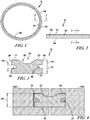
- a strip seal 10 in accordance with the present disclosure is shown, for example, in Fig. 1 .
- the strip seal 10 provides compliance to allow the strip seal 10 to be pre-loaded. Additionally, the strip seal 10 may be used in applications with a broader range of groove or gap tolerances.
- the strip seal 10 has a constant cross section. In some embodiments, the strip seal 10 has a varying cross section. In some embodiments, the strip seal 10 includes features that allow a number strip seals 10 to be used within a single assembly. In some embodiments, for example, a number of strip seals 10 are assembled end to end. In some embodiments, for example, a number of strip seals 10 are stacked together to achieve a desired effect. In some embodiments, the strip seal 10 is formed into a continuous hoop, as shown in Fig. 1 , or a split hoop for sealing requirements on cylinders. In some embodiments, for example, the strip seal 10 is formed into a substantially linear ribbon as shown in Fig. 2 . In some embodiments, the strip seal 10 is formed into other polygonal shapes.
- the strip seal 10 may be made from a number of different materials.
- the strip seal 10 is formed from at least one of carbon, silicon carbide, alumina, aluminosilicate or other carbide, nitride, boride or glass fibers.
- the strip seal 10 includes a reinforcement structure 20.
- the reinforcement structure 20 is a laminate and includes multidirectional reinforcements, for example, fabric, chopped fiber mat, or uni-directional layers.
- the reinforcement structure 20 is locally stitched, woven, or otherwise reinforced to increase mechanical integrity.
- the reinforcement structure 20 is entirely stitched, woven, or otherwise reinforced to maximize mechanical integrity.
- the strip seal 10 includes a matrix material 12.
- the matrix material 12 may be, for example, silicon, silicon carbide, carbon, boron carbide, alumina, aluminosilicate or any other desirable ceramic including combinations.
- the strip seal 10 is made of a combination of fibers and/or matrices as required by the design to optimize performance and cost.
- the strip seal 10 includes a coating 14 for protection from the operational environment.
- the coating 14 is thin.
- the strip seal 10 includes no coating 14.
- the strip seal 10 may be configured to adjust the level of the preload applied to the strip seal 10, seal maximum deflection, seal dynamic behavior, and seal stiffness.
- the strip seal 10 is flexible and deforms plastically.
- the shape of the strip seal 10 and the process used to form the strip seal 10 gives the strip seal 10 flexibility.
- the strip seal 10 may be formed to have one of a variety of cross-sections.
- a first embodiment of the strip seal 10 has a first cross-section is shown in Figs. 1-8 .
- the strip seal 10 is formed using a number of layers to give the strip seal 10 shape and flexibility.
- the strip seal 10 is formed from ceramic matrix composite 70.
- the ceramic matrix composite 70 includes a ceramic matrix 72 and a number of ceramic fiber fabrics 74 embedded in the ceramic matrix 72 as shown in Figs. 7A and 7B .
- the number of ceramic fiber fabrics 74 may be embedded in the ceramic matrix 72 by a variety of methods.
- the ceramic fiber fabrics 74 may be embedded in the ceramic matrix 72 by chemical vapor infiltration (CVI) or polymer infiltration. Any number of ceramic fiber fabrics 74 may be embedded in the ceramic matrix 72 in a given process.
- CVI chemical vapor infiltration
- all of the ceramic fiber fabrics 74 are embedded in the ceramic matrix 72 in one process. In some embodiments, the ceramic fiber fabrics 74 are embedded in the ceramic matrix 72 one at a time. Additional ceramic fiber fabrics 74 impart more flexibility into the strip seal 10 than one ceramic fiber fabric 74 with an equivalent size of the additional ceramic fiber fabrics 74.
- the ceramic matrix 72 composite may be one or more of a variety of materials.
- the ceramic matrix 72 may be Silicon Carbide (SiC), alumina, and/or Boron Carbide.
- Each of the ceramic fiber fabrics 74 may be at least one of a number of different types of ceramic fiber fabrics.
- the ceramic fiber fabrics 74 may be chopped fiber, fiber tows, woven tows, or woven tows with fiber reinforcement.
- the ceramic fiber fabrics 74 may be one or more of a variety of materials.
- the ceramic fiber fabrics 74 may be Hi-Nicalon, alumina, aluminosilicate, and/or Carbon.
- the strip seal 10 includes four ceramic fiber fabrics 74 as shown in Fig. 5 .
- the ceramic fiber fabrics 74 are formed to have a desired front shape as seen in a cross-sectional view as shown in Fig. 5 .
- the ceramic fiber fabrics 74 are also formed to have a desired top shape as seen in a plan view as shown in Figs. 1 and 2 .
- the front shape of ceramic fiber fabrics 74 may be formed to give the strip seal 10 a variable amount of flexibility and to control the expansion direction of the strip seal 10.
- the strip seal 10 includes a top fabric assembly 78 and a bottom fabric assembly 80 as shown in Fig. 5 .
- the top fabric assembly 78 includes a first top fabric 82 and a second top fabric 84 spaced apart from the first top fabric 82.
- the second top fabric 84 may be spaced apart from the first top fabric 82 by any distance required to give the strip seal 10 a desired thickness and/or flexibility.
- a depression 90 is formed in the first and second top fabrics 82, 84. The depression 90 extends along the length of the strip seal 10.
- the bottom fabric assembly 80 includes a first bottom fabric 92 and a second bottom fabric 94 spaced apart from first bottom fabric 92.
- the second bottom fabric 94 may be spaced apart from the first bottom fabric 92 by any distance required to give the strip seal 10 a desired thickness and/or flexibility.
- the first and second bottom fabrics 92, 94 are about flat.
- the strip seal 10 is better at compressive loads applied vertically rather than horizontally because the bottom fabric assembly 80 is about flat.
- the fabric assemblies 78, 80 that have the ceramic fiber fabrics 74 that are about flat do not deform well when a load is parallel to the flat ceramic fiber fabrics 74.
- the strip seals 10 with the all non-flat ceramic fiber fabrics 74 perform better than the flat ceramic fiber fabrics 74 under either or both vertical and horizontal loads.
- the top fabric assembly 78 is embedded in the ceramic matrix 72 to form the top ceramic matrix composite assembly 98.
- the bottom fabric assembly 80 is embedded in the ceramic matrix 72 to form the bottom ceramic matrix composite assembly 100.
- the top and bottom fabric assemblies 78, 80 are embedded into the ceramic matrix 72 in the same process.
- the top and bottom fabric assemblies 78, 80 are embedded into the ceramic matrix 72 in different processes.
- the ceramic matrix 72 is formed between and permeates the first top fabric 82 and the second top fabric 84 to form the top ceramic matrix composite assembly 98 as shown in Fig. 6 . Likewise, the ceramic matrix 72 is formed between and permeates the first bottom fabric 92 and the second bottom fabric 94 to form the bottom ceramic matrix composite assembly 100 as shown in Fig. 6 .
- the top ceramic matrix composite assembly 98 is spaced apart from the bottom ceramic matrix composite assembly 100 by a variable distance to give the strip seal 10 a desired seal height 42 as shown in Fig. 6 .
- the top and bottom ceramic matrix composite assemblies 98, 100 are coupled together by the ceramic matrix 72 to form the strip seal 10.
- the strip seal 10 is formed in one process.
- the seal slots 48 are formed in the ceramic matrix 72 between the top and bottom ceramic matrix composite assemblies 98, 100 as shown in Fig. 7A . In some embodiments, no slots are formed in the ceramic matrix 72 and the space between the top and bottom ceramic matrix assemblies 98, 100 is entirely filled by the ceramic matrix 72 as shown in Fig. 7B .
- the strip seal 10 is coated with a coating 14.
- the coating 14 may be applied to any one or more surfaces of the strip seal 10.
- the coating 14 may have any desirable thickness.
- Each ceramic fiber fabric 74 may be formed into a desired shape.
- the ceramic fiber fabrics 74 include a number of portions having different shapes and positions to give the strip seal 10 a desired shape.
- the first top fabric 82 includes a first portion 110, a second portion 114, and a third portion 112 coupled between the first and second portions 110, 114.
- the first and second portions 110, 114 lie in a first plane.
- the third portion 112 lies in a second plane spaced apart from, parallel with, and below the first plane.
- the second top fabric 84 includes a first portion 116, a second portion 120, and a third portion 118 coupled between the first and second portions 116, 120.
- the first and second portions 116, 120 lie in the second plane.
- the third portion 118 lies in a third plane spaced apart from, parallel with, and below the second plane.
- the first bottom fabric 92 includes a first portion 122, a second portion 126, and a third portion 128 coupled between the first and second portions 122, 126.
- the first, second, and third portions 122, 126, 124 lie in a fourth plane spaced apart from, parallel with, and below the third plane.
- the second bottom fabric 94 includes a first portion 128, a second portion 132, and a third portion 130 coupled between the first and second portions 128, 132.
- the first, second, and third portions 128, 132, 130 lie in a fifth plane spaced apart from, parallel with, and below the fourth plane.
- the strip seal 10 includes an upper surface 30, a lower surface 32 spaced apart from and opposite the upper surface 30, a first side wall 34, and a second side wall 36 spaced apart from and opposite the first side wall 34.
- the upper surface 30 is spaced apart from the lower surface 32 by a seal height 42.
- the seal height 42 is equal to a seal thickness 44.
- the upper surface 30 includes a depression 90 such that the upper surface 30 forms a valley 54.
- the upper surface 30 includes obtuse angles that form the valley 54.
- the upper surface 30 includes right or acute angles that form the valley 54.
- the upper surface 30 is curved to form the valley 54.
- the first and second side walls 34, 36 are each formed to define a seal slot 48 extending the length of the strip seal 10.
- the seal slots 48 allow the strip seal 10 to deform.
- the seal slots 48 allow the top fabric assembly 78 and the bottom fabric assembly 80 to depress toward each other, compressing the size of the strip seal 10. As the strip seal 10 compresses, the strip seal 10 stores potential energy. As such, when the strip seal 10 is no longer compressed, the strip seal 10 expands towards its uncompressed shape.
- the seal slots 48 may be any desired shape. In the illustrative embodiment, the seal slots 48 are C shaped. In some embodiments, the seal slots 48 are U shaped. In some embodiments, the seal slot 48 included in the first side wall 34 has a different shape than the seal slot 48 included in the second side wall 36.
- the seal slots 48 have a seal-slot height 50 as shown in Fig. 3 .
- the seal-slot height may be a variety of magnitudes. In the illustrative embodiment, the seal-slot height 50 is about 0.015 inches when the strip seal 10 is uncompressed.
- the strip seal 10 is formed to have a desired cross-section such that the strip seal 10 is assembled with a number of components 16 having mating cross-sections.
- the components 16 may be one or more of a variety of components 16.
- the components 16 are gas turbine engine components 16 configured to be exposed to high temperatures.
- the strip seal 10 is shown assembled with a first component 16A and a second component 16B. In some embodiments, the strip seal 10 is assembled with additional components.
- the component 16A, 16B have component slots 18, 24, respectively, configured to receive a portion of the strip seal 10.
- a first component 16A includes first component slot 18 configured to receive a first portion 22 of strip seal 10 and a second component 16B includes the second component slot 24 configured to receive a second portion 26 of strip seal 10.
- the component slots 18, 24 extend through the components 16A, 16B. In some embodiments, the component slots 18, 24 extends partially through the components 16A, 16B.
- the component slots 18, 24 have a component-slot height 56.
- the component-slot height 56 is about equal to the seal height 42.
- the component-slot height 56 is less than the seal height 42, such that the strip seal 10 is compressed and/or pre-loaded when assembled in the component slots 18, 24.
- the strip seal 10 is inserted into the component slots 18, 24 and couples to the component 16A to 16B.
- the component 16A may additionally be coupled to the component 16B by one or more fasteners, for example, a bolt or screw.
- the seal slots 48 compress and the seal-slot height 50 is reduced. Preload in the strip seal 10 reduces and/or eliminates movement and wear of the strip seal 10.
- the strip seal 10 is flexible and deforms plastically when compressed.
- the seal slots 48 are sized such that when the strip seal 10 is compressed, the top fabric assembly and the bottom fabric assembly 78, 80 deform plastically and contact each other.
- the strip seal 10 is thus designed to have infinite life in terms of compression cycles because the top fabric assembly and the bottom fabric assembly 78, 80 block each other from deflecting past their plastic deformation limits.
- the strip seal 10 and the component slots 18, 24 are sized such that the strip seal 10 contacts the components 16 to create a seal between the strip seal 10 and the components 16 as well as a seal between the components 16A and 16B.
- the components 16 are exposed to high temperatures. The high temperatures cause the components 16 to expand. As the components 16 expand, the component slots 18, 24 expand.
- the strip seal 10 may not expand proportionally with the component slots 18, 24. As such, when the component slots 18, 24 expand, the strip seal 10 may loose contact with the components 16 and may partially or entirely loose its sealing ability.
- Sizing the component-slot height 56 smaller than the seal height 42 can overcome the loss of contact when the components 16 and the strip seal 10 are exposed to high temperatures.
- the strip seal 10 is preloaded and/or forced into the smaller component-slot height 56.
- the compression of the strip seal 10 by the components 16 results in contact between the strip seal 10 and the components 16 to produce an acceptable seal.
- the components 16 apply less force to the strip seal 10.
- the strip seal 10 expands towards its precompression seal height 42 as less force is applied to the strip seal 10.
- the strip seal 10 remains in contact with the components 16 because the strip seal 10 expands as the component slots 18, 24 expand. As such, the strip seal 10 maintains an acceptable seal as the components 16 and the strip seal 10 are heated.
- the component slots 18, 24 contract and compress the strip seal 10.
- the strip seal 10 is designed to experience a predetermined number of cycles of expanding and contracting without failing.
- the component slots 18, 24 may extend into the components 16 by a variety of depths. In some embodiments, the component slots 18, 24 extend into the components 16 such that the side walls 34, 36 are proximate or contacting the components 16 as shown in component 16B of Fig. 4 . In some embodiments, the component slots 18, 24 extend into the components 16 such that the side walls 34, 36 are spaced apart from the components 16 as shown in 16A of Fig. 4 .
- Figs. 8-14 are cross-sectional views of embodiments of the strip seal 10. Each Fig. 8-14 show an embodiment of the strip seal 10 having different desired geometries to give the strip seal 10 a desired geometry and flexibility and to assert pressure in a desired direction. Figs. 8-14 show only the ceramic fiber fabrics 74 of the strip seal 10. In some embodiments, the ceramic fiber fabrics 74 in Figs. 8-14 may be embedded in the ceramic matrix 72 such that a slot is formed in either or both sides of the strip seal 10 between the top and bottom ceramic matrix composite assemblies 98, 100. Fig. 8 is a cross-sectional view the strip seal 10 of Figs. 1-7B . Figs. 9 and 14 show embodiments of the strip seal 10 that include the reinforcement structure 20.
- a Hi-Nicalon ceramic fiber fabric is constructed at 30% fiber volume using an angle interlock 3D architecture.
- the ceramic fiber fabric is woven to the geometry in Fig. 8 and processed with a chemical vapor infiltration (CVI) Silicon Carbide (SiC) matrix to leave about a 0.015 inch gap between the top ceramic matrix composite assembly 98 and the bottom ceramic matrix composite assembly 100.
- CVI chemical vapor infiltration
- SiC Silicon Carbide
- the seal is designed to be preloaded by about 0.002 to 0.005 inches allowing about 0.010 inches for movement during operation.
- the seal is designed so that the stresses at max deflection will tolerate 10 10 cycles.
- the seal is used to join a set of 36 high-pressure turbine seal segments in a commercial aircraft turbine engine.
- An alumina fiber ceramic fiber fabric is constructed from a laminate with aluminosilicate fiber reinforcement in the center as shown in Fig. 12 .
- the ceramic fiber fabric is rigidized using an alumina matrix.
- the seal is designed to be preloaded by about 0.010 to 0.015 inches, allowing about 0.015 inches for movement during operation.
- the seal is designed so that the stresses at max deflection will tolerate 10 10 cycles with only 20% softening through the life.
- the seal is used to join adjacent sections of exhaust for a commercial aircraft turbine engine
- An AS4 carbon fiber ceramic fiber fabric is constructed at 38% fiber volume using an angle interlock 3D architecture.
- the ceramic fiber fabric is woven to the geometry in Fig. 14 and processed with a chemical vapor infiltration (CVI) Silicon Carbide (SiC)/Boron Carbide matrix to leave about a 0.075 inch gap between the top and bottom ceramic matrix composite assemblies.
- CVI chemical vapor infiltration
- SiC Silicon Carbide
- Boron Carbide matrix to leave about a 0.075 inch gap between the top and bottom ceramic matrix composite assemblies.
- the seal is designed to be preloaded by about 0.010 to 0.015 inches vertically, thereby applying horizontal pressure to create additional sealing surfaces.
- the seal is designed so that the stresses at max deflection will tolerate 10 5 cycles.
- the seal is used to seal the outlet of a combustor in a short life turbine engine.
Landscapes
- Engineering & Computer Science (AREA)
- Chemical & Material Sciences (AREA)
- Ceramic Engineering (AREA)
- Structural Engineering (AREA)
- Manufacturing & Machinery (AREA)
- Materials Engineering (AREA)
- Organic Chemistry (AREA)
- General Engineering & Computer Science (AREA)
- Mechanical Engineering (AREA)
- Combustion & Propulsion (AREA)
- Composite Materials (AREA)
- Chemical Kinetics & Catalysis (AREA)
- Gasket Seals (AREA)
Description
- The present disclosure relates generally to ceramic matrix composite seals, and more specifically to a ceramic matrix composite seal including a ceramic matrix and a number of ceramic fiber fabrics embedded in the ceramic matrix to form the ceramic matrix composite seal with a desired geometry.
- Economical and environmental concerns, for example, improving efficiency and reducing emissions, are driving an increasing demand for higher gas turbine operating temperatures. The temperature capability of hot section components in gas turbine engines is currently one limitation to improving efficiency and emissions of many gas turbine engines. Improvements in cooling, materials, and coatings may be able to achieve higher inlet temperatures. Therefore, interest in high temperature materials, such as, for example, ceramic-based materials is growing.
- One hot section component includes a strip seal. Strip seals, also called feather seals, may be used to eliminate leakage flow between two components arranged adjacently to one another. This may be achieved by the two components having groove recesses in edge faces that lie substantially opposite and adjacent one another. The strip seal seals the gap between the two components by being at least partially received into the groove recesses of the adjacently fitted components to span the gap between the components. The grooved recesses of fitted components often do not perfectly align due to, for example, manufacturing tolerances or thermal expansion.
-
US2010/092281 discloses a CMC strip seal that joins two gas turbine engine components. The strip extends from a slot in component 1 to a slot in component 2. The strip can contain a plurality of fiber plies, filled with a ceramic matrix material. - A ceramic matrix composite seal may include a ceramic matrix, a first fiber assembly, and a second fiber assembly. The first fiber assembly is embedded in the ceramic matrix. The first fiber assembly includes a first top fabric and a second top fabric. The second fiber assembly is embedded in the ceramic matrix. The second fiber assembly includes a first bottom fabric and a second bottom fabric. The second fiber assembly is spaced apart from and opposite the first fiber assembly.
- The second top fabric of the first fiber assembly is coupled to the first bottom fabric of the second fiber assembly by the ceramic matrix. The first top fabric and the second top fabric determine the shape of the first fiber assembly. The first bottom fabric and the second bottom fabric determine the shape of the second fiber assembly.
- In some embodiments, the second fiber assembly is about flat. The first fiber assembly includes a depression along a length of the first fiber assembly at a center of the first fiber assembly. The depression extends toward the second fiber assembly.
- In some embodiments, the first fiber assembly includes a first depression along a length of the first fiber assembly at a center of the first fiber assembly, the first depression extending toward the second fiber assembly, and the second fiber assembly includes a second depression along a length of the second fiber assembly at a center of the second fiber assembly, and the second depression extends toward the first fiber assembly.
- In some embodiments, the first top fabric may include a first portion, a second portion, and a third portion coupled between the first and the second portions. The first and second portions of the first top fabric may lie in a first plane. The third portion of the first top fabric may lie in a second plane spaced apart from, parallel with, and below the first plane.
- The second top fabric may include a first portion, a second portion, and a third portion coupled between the first and the second portions. The first and second portions of the second top fabric may lie in the second plane. The third portion of the second top fabric may lie in a third plane spaced apart from, parallel with, and below the second plane.
- The first bottom fabric may include a first portion, a second portion, and a third portion coupled between the first and the second portions. The first, second, and third portions of the first bottom fabric may lie in a fourth plane spaced apart from, parallel with, and below the third plane.
- The second bottom fabric may include a first portion, a second portion, and a third portion coupled between the first and the second portions. The first, second, and third portions of the second bottom fabric may lie in a fifth plane spaced apart from, parallel with, and below the fourth plane.
- In some embodiments, the first top fabric may include a first portion, a second portion, and a third portion coupled between the first and the second portions. The first and second portions of the first top fabric may lie in a first plane. The third portion of the first top fabric may lie in a second plane spaced apart from, parallel with, and below the first plane.
- The second top fabric may include a first portion, a second portion, and a third portion coupled between the first and the second portions. The first and second portions of the second top fabric may lie in the second plane. The third portion of the second top fabric may lie in a third plane spaced apart from, parallel with, and below the second plane.
- The first bottom fabric may include a first portion, a second portion, and a third portion coupled between the first and the second portions. The first and the second portions of the first bottom fabric may lie in a fourth plane spaced apart from, parallel with, and below the third plane. The third portion of the first bottom fabric may lie in a fifth plane spaced apart from, parallel with, and below the fourth plane.
- The second bottom fabric may include a first portion, a second portion, and a third portion coupled between the first and the second portions. The first and second portions of the second bottom fabric may lie in the fifth plane. The third portion of the second bottom fabric may lie in a sixth plane spaced apart from, parallel with, and below the fifth plane. In some embodiments, the ceramic matrix composite seal may include reinforcement structure extending through the third portions of the first top fabric, second top fabric, first bottom fabric, and the second bottom fabric in a direction about perpendicular to the first plane.
- In some embodiments, the first top fabric may include a first portion, second portions, and a third portion coupled between the first and the second portions. The first and second portions of the first top fabric may lie in a first plane. The third portion of the first top fabric may lie in a second plane spaced apart from, parallel with, and below the first plane.
- The second top fabric may include a first portion, a second portion, and a third portion coupled between the first and the second portions. The first and third portions of the second top fabric may lie in a third plane spaced apart from, parallel with, and below the second plane. The second portion of the second top fabric may lie in the second plane.
- The first bottom fabric may include a first portion, a second portion, and a third portion coupled between the first and the second portions. The first and the third portions of the first bottom fabric may lie in a fourth plane spaced apart from, parallel with, and below the third plane. The second portion of the first bottom fabric may lie in a fifth plane spaced apart from, parallel with, and below the fourth plane.
- The second bottom fabric may include a first portion, a second portion, and a third portion coupled between the first and the second portions. The first and second portions of the second bottom fabric may lie in a sixth plane spaced apart from, parallel with, and below the fifth plane. The third portion of the second bottom fabric may lie in the fifth plane.
- In some embodiments, the first top fabric may include a first portion, a second portion, and a third portion coupled between the first and the second portions. The first and third portions of the first top fabric may lie in a second plane. The second portion of the first top fabric may lie in a first plane spaced apart from, parallel with, and above the second plane.
- The second top fabric may include a first portion, a second portion, and a third portion coupled between the first and the second portions. The first and third portions of the second top fabric may lie in a third plane spaced apart from, parallel with, and below the second plane. The second portion of the second top fabric may lie in the second plane.
- The first bottom fabric may include a first portion, a second portion, and a third portion coupled between the first and the second portions. The second and the third portions of the first bottom fabric may lie in a fourth plane spaced apart from, parallel with, and below the third plane. The first portion of the first bottom fabric may lie in a fifth plane spaced apart from, parallel with, and below the fourth plane.
- The second bottom fabric may include a first portion, a second portion, and a third portion coupled between the first and the second portions. The first and second portions of the second bottom fabric may lie in a sixth plane spaced apart from, parallel with, and below the fifth plane. The third portion of the second bottom fabric may lie in the fifth plane.
- In some embodiments, the first top fabric may be curved extending downwardly toward the second top fabric in a concave shape. The second top fabric may be about flat. The first bottom fabric may be about flat. The second bottom fabric may be curved extending upwardly toward the first bottom fabric in a concave shape.
- In some embodiments, the first top fabric may be curved extending downwardly toward the second top fabric in a concave shape. The second top fabric may be curved extending downwardly toward the first bottom fabric in a concave shape. The first bottom fabric may be curved extending upwardly toward the second top fabric in a concave shape. The second bottom fabric may be curved extending upwardly toward the first bottom fabric in a concave shape.
- In some embodiments, the first and second top fabrics may have about the same shape. The first and second bottom fabrics may have about the same shape.
- In some embodiments, the first top fabric may include a first portion, second portions, and a third portion coupled between the first and the second portions. The first and second portions of the first top fabric may be curved and extend upwardly in a convex shape. The third portion of the first top fabric may be curved and extend downwardly in a concave shape. The second top fabric may be about flat. The first bottom fabric may be about flat. The second bottom fabric may include a first portion, a second portion, and a third portion coupled between the first and the second portions. The first and second portions of the second bottom fabric may be curved and extend downwardly in a convex shape. The third portion of the second bottom fabric may be curved and extend upwardly in a concave shape.
- In some embodiments, the ceramic matrix composite seal may include a reinforcement structure extending through the third portion of the first top fabric to the third portion of the second bottom fabric.
- In some embodiments, a slot may be formed in a surface of the ceramic matrix composite seal between the first and the second fiber assemblies. The slot may extend along a length of the ceramic matrix composite seal.
- These and other features of the present disclosure will become more apparent from the following description of the illustrative embodiments.
-
-
Fig. 1 is a front elevation view of an annular strip seal in accordance with the present disclosure; -
Fig. 2 is a front elevation view of a liner strip seal in accordance with the present disclosure; -
Fig. 3 is cross-sectional diagrammatic view of the strip seal ofFigs. 1 or 2 taken along line 3-3; -
Fig. 4 is a cross-sectional diagrammatic view of an exemplary sealing application using the strip seal ofFig. 2 ; -
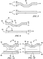
Fig. 5 is a cross-sectional diagrammatic view of another embodiment of a strip seal in accordance with the present disclosure showing that the strip seal includes a number of ceramic fiber fabrics spaced apart from each other, the ceramic fiber fabrics having a desired geometry to give the strip seal a desired geometry; -
Fig. 6 is a cross-sectional diagrammatic view of the ceramic fiber fabrics ofFig. 5 embedded in a ceramic matrix to form a top fabric assembly and a bottom fabric assembly; -
Fig. 7A is a cross-sectional diagrammatic view of another embodiment of a strip seal in accordance with the present disclosure showing that the top fabric assembly and the bottom fabric assembly may be coupled together with the ceramic matrix to form slots between the top fabric assembly and the bottom fabric assembly; -
Fig. 7B is a cross-sectional diagrammatic view of another embodiment of a strip seal in accordance with the present disclosure showing that the top fabric assembly and the bottom fabric assembly may be coupled together with the ceramic matrix such that no slots are formed between the top fabric assembly and the bottom fabric assembly; -
Fig. 8 is a cross-sectional diagrammatic view of another embodiment of a strip seal in accordance with the present disclosure with a first ceramic fiber fabric geometry; -
Fig. 9 is a cross-sectional diagrammatic view of another embodiment of a strip seal in accordance with the present disclosure with a second ceramic fiber fabric geometry, the strip seal having fiber reinforcement; -
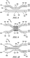
Fig. 10 is a cross-sectional diagrammatic view of another embodiment of a strip seal in accordance with the present disclosure with a third ceramic fiber fabric geometry; -
Fig. 11 is a cross-sectional diagrammatic view of another embodiment of a strip seal in accordance with the present disclosure with a fourth ceramic fiber fabric geometry; -
Fig. 12 is a cross-sectional diagrammatic view of another embodiment of a strip seal in accordance with the present disclosure with a fifth ceramic fiber fabric geometry; -
Fig. 13 is a cross-sectional diagrammatic view of another embodiment of a strip seal in accordance with the present disclosure with a sixth ceramic fiber fabric geometry; and -
Fig. 14 is a cross-sectional diagrammatic view of another embodiment of a strip seal in accordance with the present disclosure with seventh ceramic fiber fabric geometry, the strip seal having fiber reinforcement. - For the purposes of promoting an understanding of the principles of the disclosure, reference will now be made to a number of illustrative embodiments illustrated in the drawings and specific language will be used to describe the same.
- A
strip seal 10 in accordance with the present disclosure is shown, for example, inFig. 1 . Thestrip seal 10 provides compliance to allow thestrip seal 10 to be pre-loaded. Additionally, thestrip seal 10 may be used in applications with a broader range of groove or gap tolerances. - In some embodiments, the
strip seal 10 has a constant cross section. In some embodiments, thestrip seal 10 has a varying cross section. In some embodiments, thestrip seal 10 includes features that allow a number strip seals 10 to be used within a single assembly. In some embodiments, for example, a number of strip seals 10 are assembled end to end. In some embodiments, for example, a number of strip seals 10 are stacked together to achieve a desired effect. In some embodiments, thestrip seal 10 is formed into a continuous hoop, as shown inFig. 1 , or a split hoop for sealing requirements on cylinders. In some embodiments, for example, thestrip seal 10 is formed into a substantially linear ribbon as shown inFig. 2 . In some embodiments, thestrip seal 10 is formed into other polygonal shapes. - The
strip seal 10 may be made from a number of different materials. In some embodiments, thestrip seal 10 is formed from at least one of carbon, silicon carbide, alumina, aluminosilicate or other carbide, nitride, boride or glass fibers. In some embodiments, thestrip seal 10 includes areinforcement structure 20. In some embodiments, thereinforcement structure 20 is a laminate and includes multidirectional reinforcements, for example, fabric, chopped fiber mat, or uni-directional layers. In some embodiments, thereinforcement structure 20 is locally stitched, woven, or otherwise reinforced to increase mechanical integrity. In some embodiments, thereinforcement structure 20 is entirely stitched, woven, or otherwise reinforced to maximize mechanical integrity. - The
strip seal 10 includes a matrix material 12. The matrix material 12 may be, for example, silicon, silicon carbide, carbon, boron carbide, alumina, aluminosilicate or any other desirable ceramic including combinations. In some embodiments, thestrip seal 10 is made of a combination of fibers and/or matrices as required by the design to optimize performance and cost. In some embodiments, thestrip seal 10 includes acoating 14 for protection from the operational environment. In some embodiments, thecoating 14 is thin. In some embodiments, thestrip seal 10 includes nocoating 14. Thestrip seal 10 may be configured to adjust the level of the preload applied to thestrip seal 10, seal maximum deflection, seal dynamic behavior, and seal stiffness. - The
strip seal 10 is flexible and deforms plastically. The shape of thestrip seal 10 and the process used to form thestrip seal 10 gives thestrip seal 10 flexibility. Thestrip seal 10 may be formed to have one of a variety of cross-sections. A first embodiment of thestrip seal 10 has a first cross-section is shown inFigs. 1-8 . - The
strip seal 10 is formed using a number of layers to give thestrip seal 10 shape and flexibility. Thestrip seal 10 is formed fromceramic matrix composite 70. Theceramic matrix composite 70 includes aceramic matrix 72 and a number ofceramic fiber fabrics 74 embedded in theceramic matrix 72 as shown inFigs. 7A and 7B . The number ofceramic fiber fabrics 74 may be embedded in theceramic matrix 72 by a variety of methods. For example, theceramic fiber fabrics 74 may be embedded in theceramic matrix 72 by chemical vapor infiltration (CVI) or polymer infiltration. Any number ofceramic fiber fabrics 74 may be embedded in theceramic matrix 72 in a given process. - In some embodiments, for example, all of the
ceramic fiber fabrics 74 are embedded in theceramic matrix 72 in one process. In some embodiments, theceramic fiber fabrics 74 are embedded in theceramic matrix 72 one at a time. Additionalceramic fiber fabrics 74 impart more flexibility into thestrip seal 10 than oneceramic fiber fabric 74 with an equivalent size of the additionalceramic fiber fabrics 74. - The
ceramic matrix 72 composite may be one or more of a variety of materials. For example, theceramic matrix 72 may be Silicon Carbide (SiC), alumina, and/or Boron Carbide. Each of theceramic fiber fabrics 74 may be at least one of a number of different types of ceramic fiber fabrics. For example, theceramic fiber fabrics 74 may be chopped fiber, fiber tows, woven tows, or woven tows with fiber reinforcement. Theceramic fiber fabrics 74 may be one or more of a variety of materials. For example, theceramic fiber fabrics 74 may be Hi-Nicalon, alumina, aluminosilicate, and/or Carbon. - In the illustrative embodiment, the
strip seal 10 includes fourceramic fiber fabrics 74 as shown inFig. 5 . Theceramic fiber fabrics 74 are formed to have a desired front shape as seen in a cross-sectional view as shown inFig. 5 . Theceramic fiber fabrics 74 are also formed to have a desired top shape as seen in a plan view as shown inFigs. 1 and 2 . As disclosed in more detail below, the front shape ofceramic fiber fabrics 74 may be formed to give the strip seal 10 a variable amount of flexibility and to control the expansion direction of thestrip seal 10. - The
strip seal 10 includes atop fabric assembly 78 and abottom fabric assembly 80 as shown inFig. 5 . Thetop fabric assembly 78 includes a firsttop fabric 82 and a secondtop fabric 84 spaced apart from the firsttop fabric 82. The secondtop fabric 84 may be spaced apart from the firsttop fabric 82 by any distance required to give the strip seal 10 a desired thickness and/or flexibility. In the illustrative embodiment, adepression 90 is formed in the first and secondtop fabrics depression 90 extends along the length of thestrip seal 10. - The
bottom fabric assembly 80 includes afirst bottom fabric 92 and asecond bottom fabric 94 spaced apart fromfirst bottom fabric 92. Thesecond bottom fabric 94 may be spaced apart from thefirst bottom fabric 92 by any distance required to give the strip seal 10 a desired thickness and/or flexibility. In the illustrative embodiment, the first and secondbottom fabrics - In the illustrative embodiment, the
strip seal 10 is better at compressive loads applied vertically rather than horizontally because thebottom fabric assembly 80 is about flat. Thefabric assemblies ceramic fiber fabrics 74 that are about flat do not deform well when a load is parallel to the flatceramic fiber fabrics 74. As such, the strip seals 10 with the all non-flatceramic fiber fabrics 74 perform better than the flatceramic fiber fabrics 74 under either or both vertical and horizontal loads. - The
top fabric assembly 78 is embedded in theceramic matrix 72 to form the top ceramic matrixcomposite assembly 98. Thebottom fabric assembly 80 is embedded in theceramic matrix 72 to form the bottom ceramic matrixcomposite assembly 100. In some embodiments, the top andbottom fabric assemblies ceramic matrix 72 in the same process. In some embodiments, the top andbottom fabric assemblies ceramic matrix 72 in different processes. - The
ceramic matrix 72 is formed between and permeates the firsttop fabric 82 and the secondtop fabric 84 to form the top ceramic matrixcomposite assembly 98 as shown inFig. 6 . Likewise, theceramic matrix 72 is formed between and permeates thefirst bottom fabric 92 and thesecond bottom fabric 94 to form the bottom ceramic matrixcomposite assembly 100 as shown inFig. 6 . - The top ceramic matrix
composite assembly 98 is spaced apart from the bottom ceramic matrixcomposite assembly 100 by a variable distance to give the strip seal 10 a desiredseal height 42 as shown inFig. 6 . The top and bottom ceramicmatrix composite assemblies ceramic matrix 72 to form thestrip seal 10. In some embodiments, thestrip seal 10 is formed in one process. - In some embodiments, the
seal slots 48 are formed in theceramic matrix 72 between the top and bottom ceramicmatrix composite assemblies Fig. 7A . In some embodiments, no slots are formed in theceramic matrix 72 and the space between the top and bottomceramic matrix assemblies ceramic matrix 72 as shown inFig. 7B . - In some embodiments, the
strip seal 10 is coated with acoating 14. Thecoating 14 may be applied to any one or more surfaces of thestrip seal 10. Thecoating 14 may have any desirable thickness. - Each
ceramic fiber fabric 74 may be formed into a desired shape. Theceramic fiber fabrics 74 include a number of portions having different shapes and positions to give the strip seal 10 a desired shape. Referring toFig. 8 , the firsttop fabric 82 includes afirst portion 110, asecond portion 114, and athird portion 112 coupled between the first andsecond portions second portions third portion 112 lies in a second plane spaced apart from, parallel with, and below the first plane. - The second
top fabric 84 includes afirst portion 116, asecond portion 120, and athird portion 118 coupled between the first andsecond portions second portions third portion 118 lies in a third plane spaced apart from, parallel with, and below the second plane. - The
first bottom fabric 92 includes afirst portion 122, asecond portion 126, and athird portion 128 coupled between the first andsecond portions third portions - The
second bottom fabric 94 includes afirst portion 128, asecond portion 132, and athird portion 130 coupled between the first andsecond portions third portions - Referring to
Figs. 3 and 4 , thestrip seal 10 includes anupper surface 30, alower surface 32 spaced apart from and opposite theupper surface 30, afirst side wall 34, and asecond side wall 36 spaced apart from and opposite thefirst side wall 34. Theupper surface 30 is spaced apart from thelower surface 32 by aseal height 42. When thestrip seal 10 is uncompressed, theseal height 42 is equal to aseal thickness 44. - The
upper surface 30 includes adepression 90 such that theupper surface 30 forms avalley 54. In the illustrative embodiment, theupper surface 30 includes obtuse angles that form thevalley 54. In some embodiments, theupper surface 30 includes right or acute angles that form thevalley 54. In some embodiments, theupper surface 30 is curved to form thevalley 54. - The first and
second side walls seal slot 48 extending the length of thestrip seal 10. Theseal slots 48 allow thestrip seal 10 to deform. Theseal slots 48 allow thetop fabric assembly 78 and thebottom fabric assembly 80 to depress toward each other, compressing the size of thestrip seal 10. As thestrip seal 10 compresses, thestrip seal 10 stores potential energy. As such, when thestrip seal 10 is no longer compressed, thestrip seal 10 expands towards its uncompressed shape. - The
seal slots 48 may be any desired shape. In the illustrative embodiment, theseal slots 48 are C shaped. In some embodiments, theseal slots 48 are U shaped. In some embodiments, theseal slot 48 included in thefirst side wall 34 has a different shape than theseal slot 48 included in thesecond side wall 36. Theseal slots 48 have a seal-slot height 50 as shown inFig. 3 . The seal-slot height may be a variety of magnitudes. In the illustrative embodiment, the seal-slot height 50 is about 0.015 inches when thestrip seal 10 is uncompressed. - The
strip seal 10 is formed to have a desired cross-section such that thestrip seal 10 is assembled with a number of components 16 having mating cross-sections. The components 16 may be one or more of a variety of components 16. The components 16 are gas turbine engine components 16 configured to be exposed to high temperatures. Thestrip seal 10 is shown assembled with afirst component 16A and asecond component 16B. In some embodiments, thestrip seal 10 is assembled with additional components. - As shown in
Fig. 4 , thecomponent component slots 18, 24, respectively, configured to receive a portion of thestrip seal 10. Afirst component 16A includesfirst component slot 18 configured to receive afirst portion 22 ofstrip seal 10 and asecond component 16B includes the second component slot 24 configured to receive asecond portion 26 ofstrip seal 10. In some embodiments, thecomponent slots 18, 24 extend through thecomponents component slots 18, 24 extends partially through thecomponents - The
component slots 18, 24 have a component-slot height 56. In some embodiments, the component-slot height 56 is about equal to theseal height 42. In some embodiments, the component-slot height 56 is less than theseal height 42, such that thestrip seal 10 is compressed and/or pre-loaded when assembled in thecomponent slots 18, 24. Thestrip seal 10 is inserted into thecomponent slots 18, 24 and couples to thecomponent 16A to 16B. Thecomponent 16A may additionally be coupled to thecomponent 16B by one or more fasteners, for example, a bolt or screw. - When the component-
slot height 56 is less than theseal height 42, theseal slots 48 compress and the seal-slot height 50 is reduced. Preload in thestrip seal 10 reduces and/or eliminates movement and wear of thestrip seal 10. Thestrip seal 10 is flexible and deforms plastically when compressed. In the illustrative embodiment, theseal slots 48 are sized such that when thestrip seal 10 is compressed, the top fabric assembly and thebottom fabric assembly strip seal 10 is thus designed to have infinite life in terms of compression cycles because the top fabric assembly and thebottom fabric assembly - The
strip seal 10 and thecomponent slots 18, 24 are sized such that thestrip seal 10 contacts the components 16 to create a seal between thestrip seal 10 and the components 16 as well as a seal between thecomponents component slots 18, 24 expand. Thestrip seal 10 may not expand proportionally with thecomponent slots 18, 24. As such, when thecomponent slots 18, 24 expand, thestrip seal 10 may loose contact with the components 16 and may partially or entirely loose its sealing ability. - Sizing the component-
slot height 56 smaller than theseal height 42 can overcome the loss of contact when the components 16 and thestrip seal 10 are exposed to high temperatures. Thestrip seal 10 is preloaded and/or forced into the smaller component-slot height 56. When the components 16 are cool, the compression of thestrip seal 10 by the components 16 results in contact between thestrip seal 10 and the components 16 to produce an acceptable seal. As the components 16 are heated and thecomponent slots 18, 24 expand, the components 16 apply less force to thestrip seal 10. Thestrip seal 10 expands towards itsprecompression seal height 42 as less force is applied to thestrip seal 10. Thestrip seal 10 remains in contact with the components 16 because thestrip seal 10 expands as thecomponent slots 18, 24 expand. As such, thestrip seal 10 maintains an acceptable seal as the components 16 and thestrip seal 10 are heated. When the components 16 and thestrip seal 10 cool, thecomponent slots 18, 24 contract and compress thestrip seal 10. Thestrip seal 10 is designed to experience a predetermined number of cycles of expanding and contracting without failing. - The
component slots 18, 24 may extend into the components 16 by a variety of depths. In some embodiments, thecomponent slots 18, 24 extend into the components 16 such that theside walls component 16B ofFig. 4 . In some embodiments, thecomponent slots 18, 24 extend into the components 16 such that theside walls Fig. 4 . -
Figs. 8-14 are cross-sectional views of embodiments of thestrip seal 10. EachFig. 8-14 show an embodiment of thestrip seal 10 having different desired geometries to give the strip seal 10 a desired geometry and flexibility and to assert pressure in a desired direction.Figs. 8-14 show only theceramic fiber fabrics 74 of thestrip seal 10. In some embodiments, theceramic fiber fabrics 74 inFigs. 8-14 may be embedded in theceramic matrix 72 such that a slot is formed in either or both sides of thestrip seal 10 between the top and bottom ceramicmatrix composite assemblies Fig. 8 is a cross-sectional view thestrip seal 10 ofFigs. 1-7B .Figs. 9 and14 show embodiments of thestrip seal 10 that include thereinforcement structure 20. - A Hi-Nicalon ceramic fiber fabric is constructed at 30% fiber volume using an angle interlock 3D architecture. The ceramic fiber fabric is woven to the geometry in
Fig. 8 and processed with a chemical vapor infiltration (CVI) Silicon Carbide (SiC) matrix to leave about a 0.015 inch gap between the top ceramic matrixcomposite assembly 98 and the bottom ceramic matrixcomposite assembly 100. - The seal is designed to be preloaded by about 0.002 to 0.005 inches allowing about 0.010 inches for movement during operation. The seal is designed so that the stresses at max deflection will tolerate 1010 cycles. The seal is used to join a set of 36 high-pressure turbine seal segments in a commercial aircraft turbine engine.
- An alumina fiber ceramic fiber fabric is constructed from a laminate with aluminosilicate fiber reinforcement in the center as shown in
Fig. 12 . The ceramic fiber fabric is rigidized using an alumina matrix. The seal is designed to be preloaded by about 0.010 to 0.015 inches, allowing about 0.015 inches for movement during operation. The seal is designed so that the stresses at max deflection will tolerate 1010 cycles with only 20% softening through the life. The seal is used to join adjacent sections of exhaust for a commercial aircraft turbine engine - An AS4 carbon fiber ceramic fiber fabric is constructed at 38% fiber volume using an angle interlock 3D architecture. The ceramic fiber fabric is woven to the geometry in
Fig. 14 and processed with a chemical vapor infiltration (CVI) Silicon Carbide (SiC)/Boron Carbide matrix to leave about a 0.075 inch gap between the top and bottom ceramic matrix composite assemblies. - The seal is designed to be preloaded by about 0.010 to 0.015 inches vertically, thereby applying horizontal pressure to create additional sealing surfaces. The seal is designed so that the stresses at max deflection will tolerate 105 cycles. The seal is used to seal the outlet of a combustor in a short life turbine engine.
Claims (15)
- A ceramic matrix composite seal assembled with gas turbine engine components comprising:
a strip seal assembled with a first component and a second component, the first component including a first component slot for receiving a first portion of the strip seal, the second component including a second component slot for receiving a second portion of the strip seal, wherein the first and second portions of the strip seal are inserted into the first and second component slots, and wherein the strip seal comprises:a ceramic matrix,a first fiber assembly embedded in the ceramic matrix, the first fiber assembly including a first top fabric and a second top fabric, anda second fiber assembly embedded in the ceramic matrix, the second fiber assembly including a first bottom fabric and a second bottom fabric, the second fiber assembly spaced apart from and opposite the first fiber assembly,wherein the second top fabric of the first fiber assembly is coupled to the first bottom fabric of the second fiber assembly by the ceramic matrix, the first top fabric and the second top fabric determine the shape of the first fiber assembly, and the first bottom fabric and the second bottom fabric determine the shape of the second fiber assembly. - The ceramic matrix composite seal assembled with gas turbine engine components of claim 1, wherein the second fiber assembly is about flat and the first fiber assembly includes a depression along a length of the first fiber assembly at a center of the first fiber assembly, and the depression extends toward the second fiber assembly.
- The ceramic matrix composite seal assembled with gas turbine engine components of claim 1, wherein the first fiber assembly includes a first depression along a length of the first fiber assembly at a center of the first fiber assembly, the first depression extending toward the second fiber assembly, and the second fiber assembly includes a second depression along a length of the second fiber assembly at a center of the second fiber assembly, and
the second depression extends toward the first fiber assembly. - The ceramic matrix composite seal assembled with gas turbine engine components of claim 1, wherein the first top fabric includes a first portion, a second portion, and a third portion coupled between the first and the second portions, the first and second portions of the first top fabric lie in a first plane, the third portion of the first top fabric lies in a second plane spaced apart from, parallel with, and below the first plane,
the second top fabric includes a first portion, a second portion, and a third portion coupled between the first and the second portions, the first and second portions of the second top fabric lie in the second plane, the third portion of the second top fabric lies in a third plane spaced apart from, parallel with, and below the second plane,
the first bottom fabric includes a first portion, a second portion, and a third portion coupled between the first and the second portions, the first, second, and third portions of the first bottom fabric lie in a fourth plane spaced apart from, parallel with, and below the third plane, and
the second bottom fabric includes a first portion, a second portion, and a third portion coupled between the first and the second portions, the first, second, and third portions of the second bottom fabric lie in a fifth plane spaced apart from, parallel with, and below the fourth plane. - The ceramic matrix composite seal assembled with gas turbine engine components of claim 1, wherein the first top fabric includes a first portion, a second portion, and a third portion coupled between the first and the second portions, the first and second portions of the first top fabric lie in a first plane, the third portion of the first top fabric lies in a second plane spaced apart from, parallel with, and below the first plane,
the second top fabric includes a first portion, a second portion, and a third portion coupled between the first and the second portions, the first and second portions of the second top fabric lie in the second plane, the third portion of the second top fabric lies in a third plane spaced apart from, parallel with, and below the second plane,
the first bottom fabric includes a first portion, a second portion, and a third portion coupled between the first and the second portions, the first and the second portions of the first bottom fabric lie in a fourth plane spaced apart from, parallel with, and below the third plane, the third portion of the first bottom fabric lies in a fifth plane spaced apart from, parallel with, and below the fourth plane, and
the second bottom fabric includes a first portion, a second portion, and a third portion coupled between the first and the second portions, the first and
second portions of the second bottom fabric lie in the fifth plane, and the third portion of the second bottom fabric lies in a sixth plane spaced apart from, parallel with, and below the fifth plane. - The ceramic matrix composite seal assembled with gas turbine engine components of claim 5 further including reinforcement structure extending through the third portions of the first top fabric, second top fabric, first bottom fabric, and the second bottom fabric in a direction about perpendicular to the first plane.
- The ceramic matrix composite seal assembled with gas turbine engine components of claim 1, wherein the first top fabric includes a first portion, a second portion, and a third portion coupled between the first and the second portions, the first and second portions of the first top fabric lie in a first plane, the third portion of the first top fabric lies in a second plane spaced apart from, parallel with, and below the first plane,
the second top fabric includes a first portion, a second portion, and a third portion coupled between the first and the second portions, the first and third portions of the second top fabric lie in a third plane spaced apart from, parallel with, and below the second plane, the second portion of the second top fabric lies in the second plane,
the first bottom fabric includes a first portion, a second portion, and a third portion coupled between the first and the second portions, the first and the third portions of the first bottom fabric lie in a fourth plane spaced apart from, parallel with, and below the third plane, the second portion of the first bottom fabric lies in a fifth plane spaced apart from, parallel with, and below the fourth plane, and
the second bottom fabric includes a first portion, a second portion, and a third portion coupled between the first and the second portions, the first and second portions of the second bottom fabric lie in a sixth plane spaced apart from, parallel with, and below the fifth plane, and the third portion of the second bottom fabric lies in the fifth plane. - The ceramic matrix composite seal assembled with gas turbine engine components of claim 1, wherein the first top fabric includes a first portion, a second portion, and a third portion coupled between the first and the second portions, the first and third portions of the first top fabric lie in a second plane, the second portion of the first top fabric lies in a first plane spaced apart from, parallel with, and above the second plane,
the second top fabric includes a first portion, a second portion, and a third portion coupled between the first and the second portions, the first and third portions of the second top fabric lie in a third plane spaced apart from, parallel with, and below the second plane, the second portion of the second top fabric lies in the second plane,
the first bottom fabric includes a first portion, a second portion, and a third portion coupled between the first and the second portions, the second and the third portions of the first bottom fabric lie in a fourth plane spaced apart from, parallel with, and below the third plane, the first portion of the first bottom fabric lies in a fifth plane spaced apart from, parallel with, and below the fourth plane, and
the second bottom fabric includes a first portion, a second portion, and a third portion coupled between the first and the second portions, the first and second portions of the second bottom fabric lie in a sixth plane spaced apart from, parallel with, and below the fifth plane, and the third portion of the second bottom fabric lies in the fifth plane. - The ceramic matrix composite seal assembled with gas turbine engine components of claim 1, wherein the first top fabric is curved extending downwardly toward the second top fabric in a concave shape,
the second top fabric is about flat,
the first bottom fabric is about flat, and
the second bottom fabric is curved extending upwardly toward the first bottom fabric in a concave shape. - The ceramic matrix composite seal assembled with gas turbine engine components of claim 1, wherein the first top fabric is curved extending downwardly toward the second top fabric in a concave shape,
the second top fabric is curved extending downwardly toward the first bottom fabric in a concave shape,
the first bottom fabric is curved extending upwardly toward the second top fabric in a concave shape,
the second bottom fabric is curved extending upwardly toward the first bottom fabric in a concave shape. - The ceramic matrix composite seal assembled with gas turbine engine components of claim 10, wherein the first and second top fabrics have about the same shape and the first and second bottom fabrics have about the same shape.
- The ceramic matrix composite seal assembled with gas turbine engine components of claim 1, wherein the first top fabric includes a first portion, a second portions, and a third portion coupled between the first and the second portions, the first and second portions of the first top fabric are curved and extend upwardly in a convex shape, the third portion of the first top fabric is curved and extends downwardly in a concave shape,
the second top fabric is about flat,
the first bottom fabric is about flat, and
the second bottom fabric includes a first portion, a second portion, and a third portion coupled between the first and the second portions, the first and second portions of the second bottom fabric are curved and extend downwardly in a convex shape, and the third portion of the second bottom fabric is curved and extends upwardly in a concave shape. - The ceramic matrix composite seal assembled with gas turbine engine components of claim 12 further including reinforcement structure extending through the third portion of the first top fabric to the third portion of the second bottom fabric.
- The ceramic matrix composite seal assembled with gas turbine engine components of claim 13, wherein a slot is formed in a surface of the strip seal between the first and the second fiber assemblies, the slot extending along a length of the ceramic matrix composite seal.
- The ceramic matrix composite seal assembled with gas turbine engine components of claim 1 comprising:
means for providing a spring-like effect in response to locating the strip seal in the first and second component slots to cause the ceramic matrix composite seal to remain in contact with the first and second components while the components expand, contract, and vibrate.
Applications Claiming Priority (2)
| Application Number | Priority Date | Filing Date | Title |
|---|---|---|---|
| US201361792920P | 2013-03-15 | 2013-03-15 | |
| PCT/US2014/022387 WO2014150147A1 (en) | 2013-03-15 | 2014-03-10 | Flexible ceramic matrix composite seal |
Publications (2)
| Publication Number | Publication Date |
|---|---|
| EP2969554A1 EP2969554A1 (en) | 2016-01-20 |
| EP2969554B1 true EP2969554B1 (en) | 2019-05-08 |
Family
ID=50478556
Family Applications (1)
| Application Number | Title | Priority Date | Filing Date |
|---|---|---|---|
| EP14716670.6A Active EP2969554B1 (en) | 2013-03-15 | 2014-03-10 | Flexible ceramic matrix composite seal assembled with gas turbine engine components |
Country Status (3)
| Country | Link |
|---|---|
| US (1) | US9757920B2 (en) |
| EP (1) | EP2969554B1 (en) |
| WO (1) | WO2014150147A1 (en) |
Cited By (1)
| Publication number | Priority date | Publication date | Assignee | Title |
|---|---|---|---|---|
| EP4386179A1 (en) * | 2022-12-15 | 2024-06-19 | RTX Corporation | Gas turbine engine with split helical piston seal |
Families Citing this family (14)
| Publication number | Priority date | Publication date | Assignee | Title |
|---|---|---|---|---|
| JP6125329B2 (en) | 2013-05-27 | 2017-05-10 | 株式会社東芝 | Stationary seal structure |
| US20160251272A1 (en) * | 2015-02-27 | 2016-09-01 | General Electric Company | Laminate structure fabricated using chemical vapor infiltration (cvi) |
| JP6554882B2 (en) | 2015-04-07 | 2019-08-07 | 株式会社Ihi | Shield member and jet engine using the same |
| US9759079B2 (en) | 2015-05-28 | 2017-09-12 | Rolls-Royce Corporation | Split line flow path seals |
| US10408074B2 (en) * | 2016-04-25 | 2019-09-10 | United Technologies Corporation | Creep resistant axial ring seal |
| US11383494B2 (en) * | 2016-07-01 | 2022-07-12 | General Electric Company | Ceramic matrix composite articles having different localized properties and methods for forming same |
| US10794205B2 (en) | 2017-02-27 | 2020-10-06 | Rolls-Royce North American Technologies Inc. | Ceramic seal component for gas turbine engine and process of making the same |
| US10718226B2 (en) | 2017-11-21 | 2020-07-21 | Rolls-Royce Corporation | Ceramic matrix composite component assembly and seal |
| US20200095880A1 (en) * | 2018-09-24 | 2020-03-26 | United Technologies Corporation | Featherseal formed of cmc materials |
| US11078802B2 (en) | 2019-05-10 | 2021-08-03 | Rolls-Royce Plc | Turbine engine assembly with ceramic matrix composite components and end face seals |
| FR3100560B1 (en) * | 2019-09-06 | 2022-04-29 | Safran Aircraft Engines | Set for a turbomachine turbine |
| US11041399B2 (en) | 2019-11-01 | 2021-06-22 | Raytheon Technologies Corporation | CMC heat shield |
| US11519282B2 (en) | 2019-11-11 | 2022-12-06 | Raytheon Technologies Corporation | Ceramic matrix composite-based seal |
| FR3115811B1 (en) * | 2020-10-30 | 2023-02-24 | Safran Ceram | Assembly for turbine comprising sectors with laminated sealing tabs |
Citations (1)
| Publication number | Priority date | Publication date | Assignee | Title |
|---|---|---|---|---|
| US20100092281A1 (en) * | 2007-03-15 | 2010-04-15 | Snecma Propulsion Solide | Turbine ring assembly for gas turbine |
Family Cites Families (24)
| Publication number | Priority date | Publication date | Assignee | Title |
|---|---|---|---|---|
| US4989886A (en) | 1988-12-30 | 1991-02-05 | Textron Inc. | Braided filamentary sealing element |
| US5358262A (en) | 1992-10-09 | 1994-10-25 | Rolls-Royce, Inc. | Multi-layer seal member |
| US5304031A (en) | 1993-02-25 | 1994-04-19 | The United States Of America As Represented By The Secretary Of The Air Force | Outer air seal for a gas turbine engine |
| US5615893A (en) | 1996-01-16 | 1997-04-01 | Power Packing Company, Inc. | Split face mechanical sealing rings and their use |
| GB9827889D0 (en) | 1998-12-18 | 2000-03-29 | Rolls Royce Plc | A method of manufacturing a ceramic matrix composite |
| JP2000271736A (en) | 1999-03-29 | 2000-10-03 | Taiheiyo Cement Corp | Method for joining metal-ceramics composite material |
| DE20311346U1 (en) | 2003-07-23 | 2003-10-02 | Burgmann Dichtungswerke GmbH & Co. KG, 82515 Wolfratshausen | For a common rotation with an engine shaft designed sliding ring of a mechanical seal arrangement for jet engines |
| US20050186878A1 (en) * | 2004-02-23 | 2005-08-25 | General Electric Company | Thermo-mechanical property enhancement plies for CVI/SiC ceramic matrix composite laminates |
| US20100327535A1 (en) | 2004-03-16 | 2010-12-30 | General Electric Company | Fiber seal for ceramic matrix composite components |
| US7387758B2 (en) * | 2005-02-16 | 2008-06-17 | Siemens Power Generation, Inc. | Tabbed ceramic article for improved interlaminar strength |
| US7497443B1 (en) | 2005-05-03 | 2009-03-03 | The United States Of America As Represented By The Administrator Of The National Aeronautics And Space Administration | Resilient flexible pressure-activated seal |
| US7802799B1 (en) | 2006-09-18 | 2010-09-28 | The United States Of America As Represented By The Administrator Of The National Aeronautics And Space Administration | Method of joining metallic and composite components |
| US7870738B2 (en) | 2006-09-29 | 2011-01-18 | Siemens Energy, Inc. | Gas turbine: seal between adjacent can annular combustors |
| US7771159B2 (en) | 2006-10-16 | 2010-08-10 | General Electric Company | High temperature seals and high temperature sealing systems |
| US7798769B2 (en) | 2007-02-15 | 2010-09-21 | Siemens Energy, Inc. | Flexible, high-temperature ceramic seal element |
| US8974891B2 (en) | 2007-10-26 | 2015-03-10 | Coi Ceramics, Inc. | Thermal protection systems comprising flexible regions of inter-bonded lamina of ceramic matrix composite material and methods of forming the same |
| KR101512379B1 (en) | 2008-07-01 | 2015-04-16 | 삼성전자 주식회사 | Integrated circuit device for processing signal and image processing apparatus having the same |
| US8132442B2 (en) * | 2008-09-22 | 2012-03-13 | Siemens Energy, Inc. | Compressible ceramic seal |
| ATE537333T1 (en) | 2009-01-28 | 2011-12-15 | Alstom Technology Ltd | STRIP SEAL AND METHOD OF DESIGNING A STRIP SEAL |
| US8293356B2 (en) | 2009-05-12 | 2012-10-23 | Siemens Energy, Inc. | Subsurface inclusions of objects for increasing interlaminar shear strength of a ceramic matrix composite structure |
| US8629592B2 (en) | 2009-06-25 | 2014-01-14 | General Electric Company | Hermetic sealing assembly and electrical device including the same |
| US8359865B2 (en) | 2010-02-04 | 2013-01-29 | United Technologies Corporation | Combustor liner segment seal member |
| US8359866B2 (en) | 2010-02-04 | 2013-01-29 | United Technologies Corporation | Combustor liner segment seal member |
| JP5691409B2 (en) | 2010-11-01 | 2015-04-01 | イビデン株式会社 | C / C composite material and method for producing C / C composite material |
-
2013
- 2013-12-26 US US14/140,663 patent/US9757920B2/en not_active Expired - Fee Related
-
2014
- 2014-03-10 EP EP14716670.6A patent/EP2969554B1/en active Active
- 2014-03-10 WO PCT/US2014/022387 patent/WO2014150147A1/en not_active Ceased
Patent Citations (1)
| Publication number | Priority date | Publication date | Assignee | Title |
|---|---|---|---|---|
| US20100092281A1 (en) * | 2007-03-15 | 2010-04-15 | Snecma Propulsion Solide | Turbine ring assembly for gas turbine |
Cited By (1)
| Publication number | Priority date | Publication date | Assignee | Title |
|---|---|---|---|---|
| EP4386179A1 (en) * | 2022-12-15 | 2024-06-19 | RTX Corporation | Gas turbine engine with split helical piston seal |
Also Published As
| Publication number | Publication date |
|---|---|
| WO2014150147A1 (en) | 2014-09-25 |
| US9757920B2 (en) | 2017-09-12 |
| EP2969554A1 (en) | 2016-01-20 |
| US20140363622A1 (en) | 2014-12-11 |
Similar Documents
| Publication | Publication Date | Title |
|---|---|---|
| EP2969554B1 (en) | Flexible ceramic matrix composite seal assembled with gas turbine engine components | |
| US9291060B2 (en) | High strength joints in ceramic matrix composite preforms | |
| US20070020105A1 (en) | Lamellate CMC structure with interlock to metallic support structure | |
| US20070140835A1 (en) | Cooling systems for stacked laminate cmc vane | |
| US7753643B2 (en) | Stacked laminate bolted ring segment | |
| US7153096B2 (en) | Stacked laminate CMC turbine vane | |
| US8132442B2 (en) | Compressible ceramic seal | |
| US9267388B2 (en) | Shroud segment producing method and shroud segment | |
| KR100447840B1 (en) | Manufacturing method for carbon-carbon composites | |
| CN101551123B (en) | Gas turbine combustion chamber having inner and outer walls subdivided into sectors | |
| US9546562B2 (en) | Seal segment | |
| US20180363506A1 (en) | A turbine ring assembly with resilient retention when cold | |
| US20120125585A1 (en) | Cmc wall structure with integral cooling channels | |
| EP2774905B1 (en) | Ceramic matrix composite | |
| CN107709708A (en) | Axial Turbine Ring Assembly | |
| US20160003106A1 (en) | Method for the production of a curved ceramic sound attenuation panel | |
| US20180106160A1 (en) | Turbine shroud with i-beam construction | |
| US11149590B2 (en) | Ceramic matrix composite joints | |
| CN106609788B (en) | Whisker reinforced high fracture toughness ceramic threaded fastener | |
| CN105888885A (en) | Novel connecting structure for composite-material spray pipe extending section and short spray pipe thrust chamber of rocket engine | |
| EP3556739B1 (en) | Gang channel | |
| JP5889481B2 (en) | Insulator and manufacturing method thereof | |
| KR102418743B1 (en) | Muffle structure for cylindrical furnace made of carbon/carbon composite material | |
| US20070186396A1 (en) | Carbon-carbon parts and methods for making same | |
| US20150079317A1 (en) | Method for producing a thermal insulation body |
Legal Events
| Date | Code | Title | Description |
|---|---|---|---|
| PUAI | Public reference made under article 153(3) epc to a published international application that has entered the european phase |
Free format text: ORIGINAL CODE: 0009012 |
|
| 17P | Request for examination filed |
Effective date: 20150814 |
|
| AK | Designated contracting states |
Kind code of ref document: A1 Designated state(s): AL AT BE BG CH CY CZ DE DK EE ES FI FR GB GR HR HU IE IS IT LI LT LU LV MC MK MT NL NO PL PT RO RS SE SI SK SM TR |
|
| AX | Request for extension of the european patent |
Extension state: BA ME |
|
| DAX | Request for extension of the european patent (deleted) | ||
| STAA | Information on the status of an ep patent application or granted ep patent |
Free format text: STATUS: EXAMINATION IS IN PROGRESS |
|
| 17Q | First examination report despatched |
Effective date: 20180403 |
|
| GRAP | Despatch of communication of intention to grant a patent |
Free format text: ORIGINAL CODE: EPIDOSNIGR1 |
|
| STAA | Information on the status of an ep patent application or granted ep patent |
Free format text: STATUS: GRANT OF PATENT IS INTENDED |
|
| RIC1 | Information provided on ipc code assigned before grant |
Ipc: C04B 35/563 20060101ALI20181127BHEP Ipc: C04B 35/117 20060101ALI20181127BHEP Ipc: C04B 35/80 20060101ALI20181127BHEP Ipc: C04B 35/565 20060101ALI20181127BHEP Ipc: F01D 11/00 20060101ALI20181127BHEP Ipc: F02C 7/28 20060101ALI20181127BHEP Ipc: B32B 18/00 20060101AFI20181127BHEP |
|
| INTG | Intention to grant announced |
Effective date: 20181212 |
|
| GRAS | Grant fee paid |
Free format text: ORIGINAL CODE: EPIDOSNIGR3 |
|
| GRAA | (expected) grant |
Free format text: ORIGINAL CODE: 0009210 |
|
| STAA | Information on the status of an ep patent application or granted ep patent |
Free format text: STATUS: THE PATENT HAS BEEN GRANTED |
|
| AK | Designated contracting states |
Kind code of ref document: B1 Designated state(s): AL AT BE BG CH CY CZ DE DK EE ES FI FR GB GR HR HU IE IS IT LI LT LU LV MC MK MT NL NO PL PT RO RS SE SI SK SM TR |
|
| REG | Reference to a national code |
Ref country code: GB Ref legal event code: FG4D |
|
| REG | Reference to a national code |
Ref country code: CH Ref legal event code: EP Ref country code: AT Ref legal event code: REF Ref document number: 1129523 Country of ref document: AT Kind code of ref document: T Effective date: 20190515 |
|
| REG | Reference to a national code |
Ref country code: DE Ref legal event code: R096 Ref document number: 602014046244 Country of ref document: DE Ref country code: IE Ref legal event code: FG4D |
|
| REG | Reference to a national code |
Ref country code: NL Ref legal event code: MP Effective date: 20190508 |
|
| REG | Reference to a national code |
Ref country code: LT Ref legal event code: MG4D |
|
| PG25 | Lapsed in a contracting state [announced via postgrant information from national office to epo] |
Ref country code: LT Free format text: LAPSE BECAUSE OF FAILURE TO SUBMIT A TRANSLATION OF THE DESCRIPTION OR TO PAY THE FEE WITHIN THE PRESCRIBED TIME-LIMIT Effective date: 20190508 Ref country code: NL Free format text: LAPSE BECAUSE OF FAILURE TO SUBMIT A TRANSLATION OF THE DESCRIPTION OR TO PAY THE FEE WITHIN THE PRESCRIBED TIME-LIMIT Effective date: 20190508 Ref country code: HR Free format text: LAPSE BECAUSE OF FAILURE TO SUBMIT A TRANSLATION OF THE DESCRIPTION OR TO PAY THE FEE WITHIN THE PRESCRIBED TIME-LIMIT Effective date: 20190508 Ref country code: PT Free format text: LAPSE BECAUSE OF FAILURE TO SUBMIT A TRANSLATION OF THE DESCRIPTION OR TO PAY THE FEE WITHIN THE PRESCRIBED TIME-LIMIT Effective date: 20190908 Ref country code: FI Free format text: LAPSE BECAUSE OF FAILURE TO SUBMIT A TRANSLATION OF THE DESCRIPTION OR TO PAY THE FEE WITHIN THE PRESCRIBED TIME-LIMIT Effective date: 20190508 Ref country code: SE Free format text: LAPSE BECAUSE OF FAILURE TO SUBMIT A TRANSLATION OF THE DESCRIPTION OR TO PAY THE FEE WITHIN THE PRESCRIBED TIME-LIMIT Effective date: 20190508 Ref country code: AL Free format text: LAPSE BECAUSE OF FAILURE TO SUBMIT A TRANSLATION OF THE DESCRIPTION OR TO PAY THE FEE WITHIN THE PRESCRIBED TIME-LIMIT Effective date: 20190508 Ref country code: NO Free format text: LAPSE BECAUSE OF FAILURE TO SUBMIT A TRANSLATION OF THE DESCRIPTION OR TO PAY THE FEE WITHIN THE PRESCRIBED TIME-LIMIT Effective date: 20190808 Ref country code: ES Free format text: LAPSE BECAUSE OF FAILURE TO SUBMIT A TRANSLATION OF THE DESCRIPTION OR TO PAY THE FEE WITHIN THE PRESCRIBED TIME-LIMIT Effective date: 20190508 |
|
| PG25 | Lapsed in a contracting state [announced via postgrant information from national office to epo] |
Ref country code: BG Free format text: LAPSE BECAUSE OF FAILURE TO SUBMIT A TRANSLATION OF THE DESCRIPTION OR TO PAY THE FEE WITHIN THE PRESCRIBED TIME-LIMIT Effective date: 20190808 Ref country code: GR Free format text: LAPSE BECAUSE OF FAILURE TO SUBMIT A TRANSLATION OF THE DESCRIPTION OR TO PAY THE FEE WITHIN THE PRESCRIBED TIME-LIMIT Effective date: 20190809 Ref country code: RS Free format text: LAPSE BECAUSE OF FAILURE TO SUBMIT A TRANSLATION OF THE DESCRIPTION OR TO PAY THE FEE WITHIN THE PRESCRIBED TIME-LIMIT Effective date: 20190508 Ref country code: LV Free format text: LAPSE BECAUSE OF FAILURE TO SUBMIT A TRANSLATION OF THE DESCRIPTION OR TO PAY THE FEE WITHIN THE PRESCRIBED TIME-LIMIT Effective date: 20190508 |
|
| REG | Reference to a national code |
Ref country code: AT Ref legal event code: MK05 Ref document number: 1129523 Country of ref document: AT Kind code of ref document: T Effective date: 20190508 |
|
| PG25 | Lapsed in a contracting state [announced via postgrant information from national office to epo] |
Ref country code: EE Free format text: LAPSE BECAUSE OF FAILURE TO SUBMIT A TRANSLATION OF THE DESCRIPTION OR TO PAY THE FEE WITHIN THE PRESCRIBED TIME-LIMIT Effective date: 20190508 Ref country code: AT Free format text: LAPSE BECAUSE OF FAILURE TO SUBMIT A TRANSLATION OF THE DESCRIPTION OR TO PAY THE FEE WITHIN THE PRESCRIBED TIME-LIMIT Effective date: 20190508 Ref country code: SK Free format text: LAPSE BECAUSE OF FAILURE TO SUBMIT A TRANSLATION OF THE DESCRIPTION OR TO PAY THE FEE WITHIN THE PRESCRIBED TIME-LIMIT Effective date: 20190508 Ref country code: DK Free format text: LAPSE BECAUSE OF FAILURE TO SUBMIT A TRANSLATION OF THE DESCRIPTION OR TO PAY THE FEE WITHIN THE PRESCRIBED TIME-LIMIT Effective date: 20190508 Ref country code: RO Free format text: LAPSE BECAUSE OF FAILURE TO SUBMIT A TRANSLATION OF THE DESCRIPTION OR TO PAY THE FEE WITHIN THE PRESCRIBED TIME-LIMIT Effective date: 20190508 Ref country code: CZ Free format text: LAPSE BECAUSE OF FAILURE TO SUBMIT A TRANSLATION OF THE DESCRIPTION OR TO PAY THE FEE WITHIN THE PRESCRIBED TIME-LIMIT Effective date: 20190508 |
|
| REG | Reference to a national code |
Ref country code: DE Ref legal event code: R097 Ref document number: 602014046244 Country of ref document: DE |
|
| PG25 | Lapsed in a contracting state [announced via postgrant information from national office to epo] |
Ref country code: SM Free format text: LAPSE BECAUSE OF FAILURE TO SUBMIT A TRANSLATION OF THE DESCRIPTION OR TO PAY THE FEE WITHIN THE PRESCRIBED TIME-LIMIT Effective date: 20190508 Ref country code: IT Free format text: LAPSE BECAUSE OF FAILURE TO SUBMIT A TRANSLATION OF THE DESCRIPTION OR TO PAY THE FEE WITHIN THE PRESCRIBED TIME-LIMIT Effective date: 20190508 |
|
| PLBE | No opposition filed within time limit |
Free format text: ORIGINAL CODE: 0009261 |
|
| STAA | Information on the status of an ep patent application or granted ep patent |
Free format text: STATUS: NO OPPOSITION FILED WITHIN TIME LIMIT |
|
| PG25 | Lapsed in a contracting state [announced via postgrant information from national office to epo] |
Ref country code: TR Free format text: LAPSE BECAUSE OF FAILURE TO SUBMIT A TRANSLATION OF THE DESCRIPTION OR TO PAY THE FEE WITHIN THE PRESCRIBED TIME-LIMIT Effective date: 20190508 |
|
| 26N | No opposition filed |
Effective date: 20200211 |
|
| PG25 | Lapsed in a contracting state [announced via postgrant information from national office to epo] |
Ref country code: PL Free format text: LAPSE BECAUSE OF FAILURE TO SUBMIT A TRANSLATION OF THE DESCRIPTION OR TO PAY THE FEE WITHIN THE PRESCRIBED TIME-LIMIT Effective date: 20190508 |
|
| PGFP | Annual fee paid to national office [announced via postgrant information from national office to epo] |
Ref country code: DE Payment date: 20200327 Year of fee payment: 7 |
|
| PG25 | Lapsed in a contracting state [announced via postgrant information from national office to epo] |
Ref country code: SI Free format text: LAPSE BECAUSE OF FAILURE TO SUBMIT A TRANSLATION OF THE DESCRIPTION OR TO PAY THE FEE WITHIN THE PRESCRIBED TIME-LIMIT Effective date: 20190508 |
|
| PGFP | Annual fee paid to national office [announced via postgrant information from national office to epo] |
Ref country code: FR Payment date: 20200325 Year of fee payment: 7 |
|
| PG25 | Lapsed in a contracting state [announced via postgrant information from national office to epo] |
Ref country code: MC Free format text: LAPSE BECAUSE OF FAILURE TO SUBMIT A TRANSLATION OF THE DESCRIPTION OR TO PAY THE FEE WITHIN THE PRESCRIBED TIME-LIMIT Effective date: 20190508 |
|
| REG | Reference to a national code |
Ref country code: CH Ref legal event code: PL |
|
| REG | Reference to a national code |
Ref country code: BE Ref legal event code: MM Effective date: 20200331 |
|
| PG25 | Lapsed in a contracting state [announced via postgrant information from national office to epo] |
Ref country code: LU Free format text: LAPSE BECAUSE OF NON-PAYMENT OF DUE FEES Effective date: 20200310 |
|
| PG25 | Lapsed in a contracting state [announced via postgrant information from national office to epo] |
Ref country code: CH Free format text: LAPSE BECAUSE OF NON-PAYMENT OF DUE FEES Effective date: 20200331 Ref country code: LI Free format text: LAPSE BECAUSE OF NON-PAYMENT OF DUE FEES Effective date: 20200331 Ref country code: IE Free format text: LAPSE BECAUSE OF NON-PAYMENT OF DUE FEES Effective date: 20200310 |
|
| PG25 | Lapsed in a contracting state [announced via postgrant information from national office to epo] |
Ref country code: BE Free format text: LAPSE BECAUSE OF NON-PAYMENT OF DUE FEES Effective date: 20200331 |
|
| GBPC | Gb: european patent ceased through non-payment of renewal fee |
Effective date: 20200310 |
|
| PG25 | Lapsed in a contracting state [announced via postgrant information from national office to epo] |
Ref country code: GB Free format text: LAPSE BECAUSE OF NON-PAYMENT OF DUE FEES Effective date: 20200310 |
|
| REG | Reference to a national code |
Ref country code: DE Ref legal event code: R119 Ref document number: 602014046244 Country of ref document: DE |
|
| PG25 | Lapsed in a contracting state [announced via postgrant information from national office to epo] |
Ref country code: DE Free format text: LAPSE BECAUSE OF NON-PAYMENT OF DUE FEES Effective date: 20211001 Ref country code: FR Free format text: LAPSE BECAUSE OF NON-PAYMENT OF DUE FEES Effective date: 20210331 |
|
| PG25 | Lapsed in a contracting state [announced via postgrant information from national office to epo] |
Ref country code: MT Free format text: LAPSE BECAUSE OF FAILURE TO SUBMIT A TRANSLATION OF THE DESCRIPTION OR TO PAY THE FEE WITHIN THE PRESCRIBED TIME-LIMIT Effective date: 20190508 Ref country code: CY Free format text: LAPSE BECAUSE OF FAILURE TO SUBMIT A TRANSLATION OF THE DESCRIPTION OR TO PAY THE FEE WITHIN THE PRESCRIBED TIME-LIMIT Effective date: 20190508 |
|
| PG25 | Lapsed in a contracting state [announced via postgrant information from national office to epo] |
Ref country code: MK Free format text: LAPSE BECAUSE OF FAILURE TO SUBMIT A TRANSLATION OF THE DESCRIPTION OR TO PAY THE FEE WITHIN THE PRESCRIBED TIME-LIMIT Effective date: 20190508 Ref country code: IS Free format text: LAPSE BECAUSE OF FAILURE TO SUBMIT A TRANSLATION OF THE DESCRIPTION OR TO PAY THE FEE WITHIN THE PRESCRIBED TIME-LIMIT Effective date: 20190908 |
|
| P01 | Opt-out of the competence of the unified patent court (upc) registered |
Effective date: 20230528 |