EP2969096B1 - Bottle pressurization delivery system - Google Patents
Bottle pressurization delivery system Download PDFInfo
- Publication number
- EP2969096B1 EP2969096B1 EP14767684.5A EP14767684A EP2969096B1 EP 2969096 B1 EP2969096 B1 EP 2969096B1 EP 14767684 A EP14767684 A EP 14767684A EP 2969096 B1 EP2969096 B1 EP 2969096B1
- Authority
- EP
- European Patent Office
- Prior art keywords
- container
- fluid
- fluid medium
- port
- instrument
- Prior art date
- Legal status (The legal status is an assumption and is not a legal conclusion. Google has not performed a legal analysis and makes no representation as to the accuracy of the status listed.)
- Active
Links
- 239000012530 fluid Substances 0.000 claims description 316
- 238000000034 method Methods 0.000 claims description 18
- 230000000712 assembly Effects 0.000 claims description 11
- 238000000429 assembly Methods 0.000 claims description 11
- 230000008878 coupling Effects 0.000 claims description 5
- 238000010168 coupling process Methods 0.000 claims description 5
- 238000005859 coupling reaction Methods 0.000 claims description 5
- 230000007423 decrease Effects 0.000 claims description 5
- 238000011049 filling Methods 0.000 claims description 3
- 238000012544 monitoring process Methods 0.000 claims description 2
- 238000004128 high performance liquid chromatography Methods 0.000 claims 4
- 239000003153 chemical reaction reagent Substances 0.000 description 183
- 239000007789 gas Substances 0.000 description 68
- 239000002699 waste material Substances 0.000 description 66
- 239000003085 diluting agent Substances 0.000 description 41
- 239000000872 buffer Substances 0.000 description 35
- 239000002904 solvent Substances 0.000 description 34
- 230000006837 decompression Effects 0.000 description 23
- 238000001514 detection method Methods 0.000 description 15
- 239000000463 material Substances 0.000 description 10
- 238000000926 separation method Methods 0.000 description 9
- 239000000203 mixture Substances 0.000 description 7
- 239000012071 phase Substances 0.000 description 7
- WEVYAHXRMPXWCK-UHFFFAOYSA-N Acetonitrile Chemical compound CC#N WEVYAHXRMPXWCK-UHFFFAOYSA-N 0.000 description 6
- OKKJLVBELUTLKV-UHFFFAOYSA-N Methanol Chemical compound OC OKKJLVBELUTLKV-UHFFFAOYSA-N 0.000 description 6
- RTZKZFJDLAIYFH-UHFFFAOYSA-N Diethyl ether Chemical compound CCOCC RTZKZFJDLAIYFH-UHFFFAOYSA-N 0.000 description 5
- 230000003993 interaction Effects 0.000 description 5
- 239000007788 liquid Substances 0.000 description 5
- 239000002594 sorbent Substances 0.000 description 5
- 238000010790 dilution Methods 0.000 description 4
- 239000012895 dilution Substances 0.000 description 4
- 238000012545 processing Methods 0.000 description 4
- 238000003860 storage Methods 0.000 description 4
- ZWEHNKRNPOVVGH-UHFFFAOYSA-N 2-Butanone Chemical compound CCC(C)=O ZWEHNKRNPOVVGH-UHFFFAOYSA-N 0.000 description 3
- QTBSBXVTEAMEQO-UHFFFAOYSA-N Acetic acid Chemical compound CC(O)=O QTBSBXVTEAMEQO-UHFFFAOYSA-N 0.000 description 3
- CSCPPACGZOOCGX-UHFFFAOYSA-N Acetone Chemical compound CC(C)=O CSCPPACGZOOCGX-UHFFFAOYSA-N 0.000 description 3
- YMWUJEATGCHHMB-UHFFFAOYSA-N Dichloromethane Chemical compound ClCCl YMWUJEATGCHHMB-UHFFFAOYSA-N 0.000 description 3
- XEKOWRVHYACXOJ-UHFFFAOYSA-N Ethyl acetate Chemical compound CCOC(C)=O XEKOWRVHYACXOJ-UHFFFAOYSA-N 0.000 description 3
- KFZMGEQAYNKOFK-UHFFFAOYSA-N Isopropanol Chemical compound CC(C)O KFZMGEQAYNKOFK-UHFFFAOYSA-N 0.000 description 3
- ZMXDDKWLCZADIW-UHFFFAOYSA-N N,N-Dimethylformamide Chemical compound CN(C)C=O ZMXDDKWLCZADIW-UHFFFAOYSA-N 0.000 description 3
- YXFVVABEGXRONW-UHFFFAOYSA-N Toluene Chemical compound CC1=CC=CC=C1 YXFVVABEGXRONW-UHFFFAOYSA-N 0.000 description 3
- ZMANZCXQSJIPKH-UHFFFAOYSA-N Triethylamine Chemical compound CCN(CC)CC ZMANZCXQSJIPKH-UHFFFAOYSA-N 0.000 description 3
- 238000013461 design Methods 0.000 description 3
- 230000005484 gravity Effects 0.000 description 3
- VLKZOEOYAKHREP-UHFFFAOYSA-N n-Hexane Chemical compound CCCCCC VLKZOEOYAKHREP-UHFFFAOYSA-N 0.000 description 3
- BDERNNFJNOPAEC-UHFFFAOYSA-N propan-1-ol Chemical compound CCCO BDERNNFJNOPAEC-UHFFFAOYSA-N 0.000 description 3
- XLYOFNOQVPJJNP-UHFFFAOYSA-N water Substances O XLYOFNOQVPJJNP-UHFFFAOYSA-N 0.000 description 3
- QGJOPFRUJISHPQ-UHFFFAOYSA-N Carbon disulfide Chemical compound S=C=S QGJOPFRUJISHPQ-UHFFFAOYSA-N 0.000 description 2
- HEDRZPFGACZZDS-UHFFFAOYSA-N Chloroform Chemical compound ClC(Cl)Cl HEDRZPFGACZZDS-UHFFFAOYSA-N 0.000 description 2
- RGSFGYAAUTVSQA-UHFFFAOYSA-N Cyclopentane Chemical compound C1CCCC1 RGSFGYAAUTVSQA-UHFFFAOYSA-N 0.000 description 2
- IAZDPXIOMUYVGZ-UHFFFAOYSA-N Dimethylsulphoxide Chemical compound CS(C)=O IAZDPXIOMUYVGZ-UHFFFAOYSA-N 0.000 description 2
- LFQSCWFLJHTTHZ-UHFFFAOYSA-N Ethanol Chemical compound CCO LFQSCWFLJHTTHZ-UHFFFAOYSA-N 0.000 description 2
- IMNFDUFMRHMDMM-UHFFFAOYSA-N N-Heptane Chemical compound CCCCCCC IMNFDUFMRHMDMM-UHFFFAOYSA-N 0.000 description 2
- OFBQJSOFQDEBGM-UHFFFAOYSA-N Pentane Chemical compound CCCCC OFBQJSOFQDEBGM-UHFFFAOYSA-N 0.000 description 2
- JUJWROOIHBZHMG-UHFFFAOYSA-N Pyridine Chemical compound C1=CC=NC=C1 JUJWROOIHBZHMG-UHFFFAOYSA-N 0.000 description 2
- WYURNTSHIVDZCO-UHFFFAOYSA-N Tetrahydrofuran Chemical compound C1CCOC1 WYURNTSHIVDZCO-UHFFFAOYSA-N 0.000 description 2
- 230000008901 benefit Effects 0.000 description 2
- DKPFZGUDAPQIHT-UHFFFAOYSA-N butyl acetate Chemical compound CCCCOC(C)=O DKPFZGUDAPQIHT-UHFFFAOYSA-N 0.000 description 2
- 229910052799 carbon Inorganic materials 0.000 description 2
- MVPPADPHJFYWMZ-UHFFFAOYSA-N chlorobenzene Chemical compound ClC1=CC=CC=C1 MVPPADPHJFYWMZ-UHFFFAOYSA-N 0.000 description 2
- 238000004891 communication Methods 0.000 description 2
- 238000004821 distillation Methods 0.000 description 2
- 238000001914 filtration Methods 0.000 description 2
- 238000005189 flocculation Methods 0.000 description 2
- 230000016615 flocculation Effects 0.000 description 2
- 238000002386 leaching Methods 0.000 description 2
- IVSZLXZYQVIEFR-UHFFFAOYSA-N m-xylene Chemical group CC1=CC=CC(C)=C1 IVSZLXZYQVIEFR-UHFFFAOYSA-N 0.000 description 2
- 239000012528 membrane Substances 0.000 description 2
- 239000002184 metal Substances 0.000 description 2
- 238000003032 molecular docking Methods 0.000 description 2
- 230000003287 optical effect Effects 0.000 description 2
- 239000002245 particle Substances 0.000 description 2
- 230000037361 pathway Effects 0.000 description 2
- 229920000642 polymer Polymers 0.000 description 2
- 230000008569 process Effects 0.000 description 2
- 230000004044 response Effects 0.000 description 2
- 239000000243 solution Substances 0.000 description 2
- VZGDMQKNWNREIO-UHFFFAOYSA-N tetrachloromethane Chemical compound ClC(Cl)(Cl)Cl VZGDMQKNWNREIO-UHFFFAOYSA-N 0.000 description 2
- WSLDOOZREJYCGB-UHFFFAOYSA-N 1,2-Dichloroethane Chemical compound ClCCCl WSLDOOZREJYCGB-UHFFFAOYSA-N 0.000 description 1
- RYHBNJHYFVUHQT-UHFFFAOYSA-N 1,4-Dioxane Chemical compound C1COCCO1 RYHBNJHYFVUHQT-UHFFFAOYSA-N 0.000 description 1
- DURPTKYDGMDSBL-UHFFFAOYSA-N 1-butoxybutane Chemical compound CCCCOCCCC DURPTKYDGMDSBL-UHFFFAOYSA-N 0.000 description 1
- XDTMQSROBMDMFD-UHFFFAOYSA-N Cyclohexane Chemical compound C1CCCCC1 XDTMQSROBMDMFD-UHFFFAOYSA-N 0.000 description 1
- NHTMVDHEPJAVLT-UHFFFAOYSA-N Isooctane Chemical compound CC(C)CC(C)(C)C NHTMVDHEPJAVLT-UHFFFAOYSA-N 0.000 description 1
- SECXISVLQFMRJM-UHFFFAOYSA-N N-Methylpyrrolidone Chemical compound CN1CCCC1=O SECXISVLQFMRJM-UHFFFAOYSA-N 0.000 description 1
- 239000002253 acid Substances 0.000 description 1
- 150000007513 acids Chemical class 0.000 description 1
- 238000004458 analytical method Methods 0.000 description 1
- -1 and combinations Substances 0.000 description 1
- 238000003556 assay Methods 0.000 description 1
- 239000002585 base Substances 0.000 description 1
- 239000013060 biological fluid Substances 0.000 description 1
- 230000005540 biological transmission Effects 0.000 description 1
- 239000008280 blood Substances 0.000 description 1
- 210000004369 blood Anatomy 0.000 description 1
- 239000007853 buffer solution Substances 0.000 description 1
- 230000008859 change Effects 0.000 description 1
- 230000005465 channeling Effects 0.000 description 1
- 238000004587 chromatography analysis Methods 0.000 description 1
- 150000001875 compounds Chemical class 0.000 description 1
- 239000000470 constituent Substances 0.000 description 1
- 238000010276 construction Methods 0.000 description 1
- 238000013479 data entry Methods 0.000 description 1
- 238000007872 degassing Methods 0.000 description 1
- 238000009826 distribution Methods 0.000 description 1
- 238000007688 edging Methods 0.000 description 1
- 238000010828 elution Methods 0.000 description 1
- 230000006355 external stress Effects 0.000 description 1
- 238000000605 extraction Methods 0.000 description 1
- 238000004508 fractional distillation Methods 0.000 description 1
- 239000008187 granular material Substances 0.000 description 1
- DMEGYFMYUHOHGS-UHFFFAOYSA-N heptamethylene Natural products C1CCCCCC1 DMEGYFMYUHOHGS-UHFFFAOYSA-N 0.000 description 1
- 230000002209 hydrophobic effect Effects 0.000 description 1
- 239000011261 inert gas Substances 0.000 description 1
- 238000004255 ion exchange chromatography Methods 0.000 description 1
- 238000002955 isolation Methods 0.000 description 1
- 238000004811 liquid chromatography Methods 0.000 description 1
- 238000000622 liquid--liquid extraction Methods 0.000 description 1
- 238000011068 loading method Methods 0.000 description 1
- 238000007885 magnetic separation Methods 0.000 description 1
- 238000004519 manufacturing process Methods 0.000 description 1
- 239000002609 medium Substances 0.000 description 1
- LYGJENNIWJXYER-UHFFFAOYSA-N nitromethane Chemical compound C[N+]([O-])=O LYGJENNIWJXYER-UHFFFAOYSA-N 0.000 description 1
- 238000002414 normal-phase solid-phase extraction Methods 0.000 description 1
- 239000013618 particulate matter Substances 0.000 description 1
- 239000003208 petroleum Substances 0.000 description 1
- 239000002861 polymer material Substances 0.000 description 1
- 230000037452 priming Effects 0.000 description 1
- 238000001742 protein purification Methods 0.000 description 1
- 238000000746 purification Methods 0.000 description 1
- UMJSCPRVCHMLSP-UHFFFAOYSA-N pyridine Natural products COC1=CC=CN=C1 UMJSCPRVCHMLSP-UHFFFAOYSA-N 0.000 description 1
- 238000011160 research Methods 0.000 description 1
- 238000007493 shaping process Methods 0.000 description 1
- 239000007787 solid Substances 0.000 description 1
- 238000000638 solvent extraction Methods 0.000 description 1
- 230000035882 stress Effects 0.000 description 1
- 238000012360 testing method Methods 0.000 description 1
- YLQBMQCUIZJEEH-UHFFFAOYSA-N tetrahydrofuran Natural products C=1C=COC=1 YLQBMQCUIZJEEH-UHFFFAOYSA-N 0.000 description 1
- 210000002700 urine Anatomy 0.000 description 1
Images


Classifications
-
- G—PHYSICS
- G01—MEASURING; TESTING
- G01N—INVESTIGATING OR ANALYSING MATERIALS BY DETERMINING THEIR CHEMICAL OR PHYSICAL PROPERTIES
- G01N30/00—Investigating or analysing materials by separation into components using adsorption, absorption or similar phenomena or using ion-exchange, e.g. chromatography or field flow fractionation
- G01N30/02—Column chromatography
- G01N30/26—Conditioning of the fluid carrier; Flow patterns
- G01N30/28—Control of physical parameters of the fluid carrier
- G01N30/32—Control of physical parameters of the fluid carrier of pressure or speed
-
- B—PERFORMING OPERATIONS; TRANSPORTING
- B67—OPENING, CLOSING OR CLEANING BOTTLES, JARS OR SIMILAR CONTAINERS; LIQUID HANDLING
- B67D—DISPENSING, DELIVERING OR TRANSFERRING LIQUIDS, NOT OTHERWISE PROVIDED FOR
- B67D7/00—Apparatus or devices for transferring liquids from bulk storage containers or reservoirs into vehicles or into portable containers, e.g. for retail sale purposes
- B67D7/02—Apparatus or devices for transferring liquids from bulk storage containers or reservoirs into vehicles or into portable containers, e.g. for retail sale purposes for transferring liquids other than fuel or lubricants
- B67D7/0238—Apparatus or devices for transferring liquids from bulk storage containers or reservoirs into vehicles or into portable containers, e.g. for retail sale purposes for transferring liquids other than fuel or lubricants utilising compressed air or other gas acting directly or indirectly on liquids in storage containers
- B67D7/0255—Apparatus or devices for transferring liquids from bulk storage containers or reservoirs into vehicles or into portable containers, e.g. for retail sale purposes for transferring liquids other than fuel or lubricants utilising compressed air or other gas acting directly or indirectly on liquids in storage containers squeezing collapsible or flexible storage containers
-
- G—PHYSICS
- G01—MEASURING; TESTING
- G01N—INVESTIGATING OR ANALYSING MATERIALS BY DETERMINING THEIR CHEMICAL OR PHYSICAL PROPERTIES
- G01N30/00—Investigating or analysing materials by separation into components using adsorption, absorption or similar phenomena or using ion-exchange, e.g. chromatography or field flow fractionation
- G01N30/02—Column chromatography
- G01N30/04—Preparation or injection of sample to be analysed
- G01N30/16—Injection
- G01N30/22—Injection in high pressure liquid systems
-
- G—PHYSICS
- G01—MEASURING; TESTING
- G01N—INVESTIGATING OR ANALYSING MATERIALS BY DETERMINING THEIR CHEMICAL OR PHYSICAL PROPERTIES
- G01N30/00—Investigating or analysing materials by separation into components using adsorption, absorption or similar phenomena or using ion-exchange, e.g. chromatography or field flow fractionation
- G01N30/02—Column chromatography
- G01N30/88—Integrated analysis systems specially adapted therefor, not covered by a single one of the groups G01N30/04 - G01N30/86
- G01N2030/8804—Integrated analysis systems specially adapted therefor, not covered by a single one of the groups G01N30/04 - G01N30/86 automated systems
-
- G—PHYSICS
- G01—MEASURING; TESTING
- G01N—INVESTIGATING OR ANALYSING MATERIALS BY DETERMINING THEIR CHEMICAL OR PHYSICAL PROPERTIES
- G01N30/00—Investigating or analysing materials by separation into components using adsorption, absorption or similar phenomena or using ion-exchange, e.g. chromatography or field flow fractionation
- G01N30/02—Column chromatography
- G01N30/88—Integrated analysis systems specially adapted therefor, not covered by a single one of the groups G01N30/04 - G01N30/86
- G01N2030/8881—Modular construction, specially adapted therefor
-
- Y—GENERAL TAGGING OF NEW TECHNOLOGICAL DEVELOPMENTS; GENERAL TAGGING OF CROSS-SECTIONAL TECHNOLOGIES SPANNING OVER SEVERAL SECTIONS OF THE IPC; TECHNICAL SUBJECTS COVERED BY FORMER USPC CROSS-REFERENCE ART COLLECTIONS [XRACs] AND DIGESTS
- Y10—TECHNICAL SUBJECTS COVERED BY FORMER USPC
- Y10T—TECHNICAL SUBJECTS COVERED BY FORMER US CLASSIFICATION
- Y10T137/00—Fluid handling
- Y10T137/9029—With coupling
Definitions
- the present invention resides in the field of high-pressure, or high-performance, liquid chromatography (HPLC) assays, particularly for the delivery of reagents, diluents, solvents, and other fluids an HPLC instrument and apparatus system. More specifically, the present invention is directed to a fluid handling system for the delivery of solvent fluids with positive pressure to an HPLC instrument.
- HPLC liquid chromatography
- HPLC is a chromatographic technique used to separate a mixture of compounds in analytical chemistry and biochemistry with the purpose of identifying, quantifying or purifying the individual components of the mixture.
- HPLC relies on pumps to pass a pressurized liquid and a sample mixture through a column filled with a sorbent, leading to the separation of the sample components.
- the active component of the column, the sorbent is typically a granular material made of solid particles.
- the components of the sample mixture are separated from each other due to their different degrees of interaction with the sorbent particles.
- the pressurized liquid is typically a mixture of solvents (e.g. water, acetonitrile, methanol) and is referred to as "mobile phase".
- the fluid pressure of the mobile phase plays a major role in the separation process by influencing the interactions taking place between sample components and sorbent. These interactions are physical in nature, such as hydrophobic (dispersive), dipole-dipole and ionic, most often a combination thereof.
- HPLC instruments and techniques have become increasingly sophisticated and complex, allowing for the analysis of multiple portions of a sample, utilizing a variety of different solvent fluids or analyzing a variety of samples with the same or different solvents.
- Such systems require fluid distribution systems capable of allocating precise amounts of solvents at specific pressures, for extended durations of time, and the ability to switch from one solvent to another.
- HPLC systems known in the field often require that the solvent fluids to be used by the instruments be elevated, so as to take advantage of gravity, drawing down the solvent fluids into the instrument, and thus priming the fluid lines of the HPLC instrument.
- US 8 387 817 B1 discloses a device for holding fluids in isolation, comprising an outer container and two deformable inner containers carried within the internal space of the outer container. Said device is intended to deliver fresh mobile phase in an HPLC instrument and remove used-up (waste) mobile phase therefrom. When the device is attached to the HPLC instrument, the mobile phase is suctioned from the bag by the HPLC instrument pump.
- the present invention provides the use of a container assembly for the delivery of a fluid medium, such as a solvent fluid, into a module of an HPLC instrument such as a pump set, a separation module, or a dilution module, the container assembly (being an array of bottles)comprising: an external container (hereinafter also referred to as "reagent box” “bottle” or “container”) having a first port and a second port, the external container defining an interstitial volume fluidly connected to the first port; a compressible internal container contained within the external container and being fluidly sealed from the interstitial volume, the internal container holding the fluid medium and being fluidly connected to the second port by way of a valve; a sensor located outside of the external container, configured to determine an amount of the fluid medium held within the internal container; and a non-transitory computer-readable memory, located within the external container, that stores information regarding the volume and the age of the fluid
- a fluid medium such as a solvent fluid
- Each container assembly contains an enclosed internal container (hereinafter “bag” or “pouch”), within which solutions of solvents, reagents, buffers, diluents, and/or other fluid mediums are contained.
- bag or "pouch”
- the interstitial volume of space between the bag and the inside of the bottle is then pressurized with a gas, such as air.
- the increased gas pressure exerts force on the exterior of the bag, encouraging the egress of fluid medium, such as solvent fluid, from the enclosed bag through fluid connectors.
- the fluid connectors lead into the HPLC instrument and thus the present disclosure provides solvent fluids to an HPLC instrument at a positive pressure, relative to ambient conditions.
- the container assembly includes shut-off valves on the fluid connectors of the bottles to prevent fluid egress when the bottle is outside of or not properly coupled to an HPLC instrument.
- Shut-off connectors are also used on the HPLC instrument in order to prevent the aspiration of air by pumps if a bottle is not connected.
- Each bottle position on the HPLC instrument has an individual valve for pressurization and depressurization, which is fed from a centralized reservoir and releases to ambient atmosphere. In the case of a bag failure causing the volume of space in the bottle to fill with pressurized fluid, the valves vent away from the electronics within the HPLC instrument, into drip trays.
- the bottles may be made of metal, plastic, reinforced materials, or another appropriate rigid or semi-rigid materials, in order to generally maintain the form of the bottles when under pressure.
- the structural walls of such bottle can restorably flex, expanding to a degree when under pressure and returning to a base, unexpanded state when not under pressure.
- a bottle may reside within an additional external housing, to assist in maintaining the form of and reinforce the bottles when under pressure.
- Some embodiments of the first aspect comprise a container assembly for holding a fluid medium, the container assembly comprising: an external container having a first port and a second port, the external container defining a volume fluidly connected to the first port; and an internal container contained within the external container and being fluidly sealed from the volume, the internal container holding an fluid medium and being fluidly connected to the second port by way of a valve.
- the second aspect of the present invention is a method of handling fluid medium within an HPLC instrument, comprising: mounting an internal container within an external container, the external container defining an interstitial volume fluidly sealed from the internal container; holding the fluid medium within the internal container; coupling a first port of the external container to the interstitial volume and to a pressurization system of the instrument; coupling a second port of the external container to the internal container and to a module of the instrument; compressing the internal container by filling the interstitial volume with pressurized gas through the first port; delivering the fluid medium from within the internal container at a positive pressure to the instrument through the second port; and updating information regarding the amount of fluid medium held in the container assembly on a non-transitory computer-readable memory located within the external container.
- the third aspect of the present invention is a system for the handling of a fluid medium in an HPLC instrument, comprising: a gas intake and pressurization apparatus; a plurality of container assemblies, with each container assembly comprising an external container having a first port and a second port, each external container defining a first volume fluidly connected to the first port, and a compressible internal container defining a second volume contained within the external container and being fluidly sealed from the first volume, with each first volume being fluidly connected to the gas intake and pressurization apparatus, the internal container being fluidly connected to the second port by way of a valve, and with each second volume holding a fluid medium; a module of the HPLC instrument fluidly connected to each container assembly second volume, such that fluid medium from each container assembly can enter the instrument; and a non-transitory-computer-readable memory coupled to each of the plurality of container assemblies, wherein each non-transitory-computer-readable memory stores updatable information regarding the amount of the fluid medium held in the corresponding container assembly.
- the pressurized system for the delivery of fluid medium can be used for any appropriately designed chemistry or biochemistry instrument that requires the pressurized delivery of reagents, buffers, diluents, solvents, or other fluid mediums.
- a pressurized system for the delivery of fluid mediums into an HPLC instrument and system wherein a bottle, or reagent box, is used to store and supply solvents.
- the reagent box is designed for simple and efficient loading and locking into an HPLC instrument, minimizing the time and work required to replenish reagents on an HPLC instrument.
- the reagent box may also improve the shelf life of the solvents stored within the reagent box.
- fluid medium can refer to any one of a reagent solution, a buffer solution, a solvent, a diluent, a sample fluid (such as blood, urine, or other biological fluids), and/or other fluids.
- a sample fluid such as blood, urine, or other biological fluids
- fluid mediums can be those that are used, or known in the art to be used, as part of a mobile phase in HPLC instrumentation.
- fluid mediums and the pressurized delivery of fluid mediums, can be applied toward general life science or diagnostic research fluidic instrumentation, such as instrumentation for ion exchange chromatography, protein purification, solid phase extraction, liquid-liquid extraction, distillation, fractional distillation, fluid separation, magnetic separation, stripping, membrane or mesh filtration, flocculation, elutriation, leaching, or other such instrumentation.
- the fluid medium is an HPLC solvent, i.e. a fluid specific for use with HPLC instrumentation.
- the fluid medium can be a fluid used in separation techniques, filtration techniques, extraction techniques, purification techniques, distillation techniques, flocculation techniques, elution techniques, leaching techniques, or the like.
- Exemplary fluid mediums include, but are not limited to, water, acetic acid, acetone, acetonitrile, carbon disulphide, carbon tetrachloride, chlorobenzene, chloroform, cyclohexane, cyclopentane, dichloromethane, 1,2-dichloroethane, diethyl ether, dimethylformamide, dimethylsulfoxide, dioxan, ethanol, ethyl acetate, fluoroalkanes, heptane, hexane, methanol, methyl ethyl ketone, m-xylene, n-butyl acetate, n-butyl ether, nitromethane, n-methyl pyrollidone, pentane, petroleum ether, 1-propanol, 2-propanol, pyridine, tetrahydrofuran, toluene, triethylamine, 2,2,4-trimethylpent
- the use of the reagent box further allows for easy identification of the reagent fluid contained within the bottle. This can be accomplished by color-coding the reagent box itself.
- the reagent box can be barcoded, QR-coded, or otherwise labeled with identifying data.
- the identity of an individual reagent box can be stored in a computerized database linked to a fluid instrument system, such as a HPLC system, so as to keep track of how much fluid medium has been dispensed from any given reagent box. Information regarding the content and/or volume of fluid medium remaining in a bottle can be disclosed to a user of an instrument by use of indicator lights.
- such indicator lights can indicate that the amount of fluid medium remaining in a bottle is sufficient, that the amount of fluid medium remaining in a bottle is of concern, and/or that there is no fluid medium remaining in the bottle.
- Information regarding the content and/or volume of fluid medium remaining in a bottle, and also information regarding the number of tests run on an instrument with the bottles, can be stored, displayed, and/or manipulated on a computer system coupled with the fluid instrument system.
- a barcode reader or a QR-code reader may also be connected to a computer system coupled with a fluid instrument system and provide for data entry of the information barcoded or QR-coded on a reagent box.
- the external container includes a non-transitory computer-readable memory component that can store information regarding the volume of fluid medium held in the reagent box.
- the non-transitory computer-readable memory is updatable, such that as fluid medium decreases in the reagent box, the amount of remaining fluid medium in the box is updated to store information regarding the actual amount of fluid medium in the reagent box. Accordingly, if the reagent box is transferred from one fluid instrument system to a subsequent fluid instrument system, the subsequent fluid instrument system can obtain information regarding the amount of fluid medium in the reagent box from the non-transitory computer-readable memory component.
- the non-transitory computer-readable memory component can be updated using RF transmission from the fluid instrument system, for example, using RFID.
- the non-transitory computer-readable memory component can be electronically coupled to a fluid instrument system, and thereby updated, when the reagent box is mechanically coupled to the fluid instrument system.
- the container assembly, method and system also provides for the ability to change the buffer and reagents as the HPLC instrument is operating, i.e. on-the-fly, simply by swapping out reagent boxes. This can allow for a longer operation time of a fluidic instrument consuming fluid mediums, since reagent, solvent, diluent, and buffer fluids can be replenished as needed.
- a reagent box is swapped out, air may fill the space between the fluid connections on the reagent box and the HPLC instrument.
- a debubbler such as a porous membrane allows gas to pass through but not liquid, positioned on the HPLC side of the fluid connection can be used to prevent air bubbles or pockets from entering the fluidic system.
- container assemblies can be loaded onto an HPLC instrument horizontally, in a cantilever orientation.
- This allows for an HPLC instrument configuration and design which does not require fluid mediums or other fluids to be at an elevated position on an instrument.
- This can provide for the delivery of fluid mediums at a positive pressure, thus removing the need to use gravity to draw down fluid medium fluids into the fluid lines of an instrument, e.g. in order to prime the lines of an instrument.
- reagent boxes While the bottles holding fluids are referred to herein as "reagent" boxes, it is to be understood that the fluid contents of a reagent box can include reagents, diluents, buffers, water, solvents, or any other appropriate fluid medium.
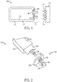
- FIG. 1 is an architectural schematic of the reagent box and its component parts 100.
- the reagent box shell 110 of the reagent box can be made of metal, plastic, polymer, metal-reinforced polymer, or other appropriate materials that can both protect the contents in the interior of the reagent box and withstand stresses related to handling and storage. Accordingly, the reagent box can be rigid or semi-rigid, particularly when considered relative to a fluid bag 102.
- the reagent box can be referred to as an external container.
- the fluid bag 102 can be made of a flexible material that holds a fluid medium, and of a size that fits within the interior of the reagent box shell 110.
- the flexible material can be an elastic, an inelastic, or a semi-elastic polymer material.
- the fluid bag 102 can be referred to as an internal container.
- the interstitial volume 104 (alternatively referred to as a first volume), being the space in between the interior surface of the reagent box shell 110 and the exterior surface of the fluid bag 102, can be filled with a gas.
- a gas such as air, can be pumped into interstitial volume 104 through a gas interface port 108.
- gas fills interstitial volume 104 of a sealed reagent box, the pressure from the gas entering the volume of the reagent box can push fluid medium inside the fluid bag 102 out through any egress that exists in the reagent box, primarily through the fluid interface port 106.
- the volume of the fluid bag 102 can be referred to as second volume.
- a reagent box shell 110 can be sealed with a reagent box cap 114 that fits over the open end region 112 of the reagent box shell 110.
- the reagent box cap 114 further includes a fluid interface connector 116 which can couple to the fluid interface port 106, and a gas interface connector 118 which can couple to the gas interface port 108.
- the gas interface connector 118 when connected to the gas interface port 108 forms a pathway that allows for gas to be pumped into the interstitial volume 104 of the reagent box shell 110.
- the fluid interface connector 116 when connected to the fluid interface port 106 forms a pathway that allows for fluid to exit the fluid bag 102, which in operation is designed to be in response to the increased gas pressure of the interstitial volume 104 pushing on the exterior surface of the fluid bag 102.
- An interface plate 120 surrounds and secures a cross-section of the fluid interface connector 116 and gas interface connector 118 to the fluid bag 102.
- FIG. 2 is an exploded-view illustration of the reagent box 200.
- the reagent box shell 202 can be made of materials that can both protect the contents in the interior of the reagent box and hold up to external stresses of handling and storage. Further, the reagent box shell 202 can be molded, contoured, or constructed in order to fit and interface with an HPLC instrument, or other fluidic instrument, as well as in order to be easily handled by a user.
- the fluid bag 204 which can be made of any appropriate flexible material capable of holding fluid, can be shaped and/or contoured to fit within the reagent box shell 202.
- the fluid bag 204 can be made of materials that are biologically inert and chemically inert, capable of withstanding the range of solvents, acids, bases, and other liquids that can have corrosive characteristics. Further, the fluid bag 204 can be shaped, tapered, and/or contoured to efficiently allow solvents to egress the fluid bag 204 through the fluid interface port 208 (alternatively referred to as a nozzle) when the exterior surface of the fluid bag 204 is under pressure. The shaping or tapering of the fluid bag 204 can mitigate against solvents being pushed to the sides, corners, or back of the fluid bag 204 when under pressure, by channeling or directing the held fluid medium toward the exit of the fluid bag 204 at the fluid interface port 208.
- the fluid medium accordingly exits the fluid bag 204 at a positive pressure. This can help to maximize the use of any fluid medium, reagent, buffer, diluent, or other solvent in a fluid bag 204 and minimize the waste of any unused solvents.
- the fluid bag 204 is bordered by flat edging that causes the fluid bag 204 to substantively flatten under pressure.
- the reagent box cap 206 can be made of the same material or a different material as the reagent box shell 202.
- the reagent box cap 206 when mechanically coupled with the reagent box shell 202, provides for a sealed (i.e. airtight) interstitial volume such that the gas in the volume between the interior surface of the reagent box shell 202 and the exterior surface of the fluid bag 204 will increase in pressure as more gas is pumped into volume.
- the seal between the coupled reagent box shell 202 and reagent box cap 206 should not break as gas pressure in the interstitial volume increases.
- the reagent box cap 206 further includes a gas interface port 214 for providing gas to the interstitial volume.
- a gas interface port O-ring 216 can be used to help secure the gas interface port 214 to a mechanical structure, such as a pipe or tube, used to channel gas into the reagent box.
- a fluid interface port O-ring 210 can be used to help secure the fluid interface port 208 as it mechanically couples with the reagent box cap 206, the reagent cap fluid port 220, and fluid interface connector 218.
- An interface connector latch 212 can be used to further secure the connection between the fluid interface connector 218 as it is seated within the reagent cap fluid port 220 and/or the fluid interface port 208.
- the fluid interface port 208 can be threaded or otherwise molded to mechanically couple with the reagent cap fluid port 220, or to guide and control the flow of fluids that egress from the fluid bag 204.
- the reagent box or container assembly may not be built from a severable reagent box cap and reagent box shell.
- the reagent box can be constructed from parts that are permanently sealed together using methods known in the art.
- ports may be formed in a single body shell using methods known in the art, through which a fluid bag may be inserted and into which interface connections can be installed.
- the reagent box shell 202 can further include a label region 222 on which a barcode, QR-code, or other identifying marking can be printed or affixed.
- a label region 222 can be on any part of the external surface of the reagent box shell 202, as appropriate for handling and identifying the reagent box individually or coupled with an HPLC instrument.
- FIG. 3 is a design flowchart illustrating the interaction and connections between all components of the bulk fluidics module 300.
- Air (or in alternative embodiments, a gas from a controlled gas supply) is drawn into the bulk fluidics module 300 through the consumable pressurization system 301.
- the consumable pressurization system 301 pressurizes the air and is sent to the reagent consumable region 302 through pressurized gas channel 315, which can be a hollow piping, tubing, or the like.
- Air pressure sensors within the consumable pressurization region 301 monitor the air pressure, sending that information to the control electronics 306. Based on that pressure data, the control electronics 306 send instructions to controllers within the consumable pressurization region 301 to regulate the air pressure therein.
- reagent boxes Within the reagent consumable region 302 there are a plurality of reagent boxes, 302a, 302b, and 302d, which can contain fluids such as solvents, reagents, buffer, or diluent.
- the pressurized air delivered to the reagent consumable region 302 through the pressurized gas channel 315 is more specifically delivered into the gas receiving structure of each reagent box.
- pressurized gas is pumped into the interstitial volume of a reagent box, fluid medium is pushed (at a positive pressure) out of the fluid bag inside the reagent box, out through the leak detection region 310 and into the consumable decompression region 311.
- the fluid medium from each reagent box is pushed through a fluid channel dedicated that fluid medium.
- fluid channel 312 is dedicated to fluid medium from reagent box 302a
- fluid channel 313 is dedicated to fluid medium from reagent box 302b
- fluid channel 314 is dedicated to fluid medium from reagent box 302d.
- there may be more than one reagent box connected to a fluid channel such that multiple reagent boxes with the same fluid, i.e. the same reagent or the same buffer, can be provided to a single fluid channel system.
- the leak detection region 310 is designed to detect leaks from the reagent consumable region 302. Leaks detected from the reagent consumable region 302 will be sensed by sensors in the leak detection region 310, where the sensors can be thermal-based sensors, voltage-based sensors, current-based sensors, or the like. Upon detection of a leak, the control electronics 306 can operate to trigger a warning indicator for a user, reduce or shut off pressurization of the reagent boxes, close valves, or execute other actions to minimize and/or stop further leakage.
- the consumable decompression region 311 includes valves that take in the fluid medium expelled from the related reagent boxes, and regulates the pressure of each fluid medium before further delivering said fluid mediums to the next stages of an HPLC instrument. From the consumable decompression region 311, the fluid medium from reagent boxes which are reagents and buffers, such as 302a and 302b, are further directed to a buffer conditioner 304, and then further directed out of the bulk fluidics module 300, such as to a separation module of the HPLC instrument.
- the fluid medium from reagent boxes which are diluents 302d are further directed from the consumable decompression region 311 to a diluent conditioner 305, and then further directed out of the bulk fluidics module 300, such as to a dilution module of the HPLC instrument.
- waste fluids from the HPLC instrument i.e. solvents run through a sorbent column
- waste fluids from the HPLC instrument are returned to the bulk fluidics module 300, specifically to the waste combiner subassembly 307.
- the waste fluids, once combined, can be further shunted to a waste container 308 as a separate section of the HPLC instrument and/or a waste pipe 309 leading out of the HPLC instrument entirely.
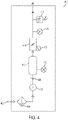
- FIG. 4 is a detailed schematic illustration of the consumable pressurization system 400.
- air from the atmosphere is drawn into the consumable pressurization system 400, and the HPLC instrument generally, through an air intake 402.
- the gas drawn into the consumable pressurization system 400 may be from a controlled source of a specific gas, such as an inert gas.
- the air drawn into the consumable pressurization system 400 then passes through an air filter 404 which filters out particulate matter, preventing such matter from entering the consumable pressurization system 400.
- the filtered air then passes through the air pump 406 and through a check valve 408 (i.e. a one-way, non-return valve) into an air reservoir 410.
- a check valve 408 i.e. a one-way, non-return valve
- a first air pressure sensor 412 which may be a pressure gauge for 0.0-2.0 bar, or may be a pressure gauge for 0.0-4.0 bar, measures the air pressure in the air reservoir 410 and communicates that information to the control electronics 306, to which the air pressure sensor 412 is electrically connected.
- the air drawn into the consumable pressurization system 400 is directed into a pressure regulator 414.
- the pressure regulator 414 is controlled by a pressure regulator controller 415, which is in turn electrically connected to the control electronics 306.
- the pressure regulator 414 compresses the air to a specified pressure and the pressurized air is measured by a second air pressure sensor 416, which can be a pressure gauge for 0.0-1.0 bar, and which in other aspects can be a pressure gauge for 0.0-4.0 bar, which is also electrically connected to the control electronics 306.
- a pressure switch 418 which closes an electrical circuit upon reaching a certain pressure, is also in contact with the pressurized.
- the pressure switch 418 can operate to, for example, open a pressure release valve, cause an indicator to communicate a signal, allow pressurized gas into the pressurized gas channel 315, and/or trigger other operations in the bulk fluidics module 300, or in the HPLC instrument generally.
- the pressurized air is then directed from the consumable pressurization system 400 to the attached reagent boxes.
- FIG. 5A is a schematic illustration of a container assembly 500, which is also referred to as a reagent box.
- a pair of reagent boxes can be used for each fluid medium to be run through the HPLC instrument.
- FIG. 5A identifies constituent parts of the illustrated reagent box with two numbers which relate to a first and second reagent box, respectively, of a pair of reagent boxes containing the same solvent.
- each element can be further defined with a suffix to identify whether a reagent, buffer, diluent, or other solvent is present in the reagent box, to allow for more precise tracking of fluid and connections in the present application.
- the reagent box shell 501/502 surrounds and defines an interstitial volume 503/504 that contains at least a fluid bag 505/506 (e.g. a reagent fluid bag 505a/506a or a diluent fluid bag 505d/506d) which can hold a fluid medium, such as an HPLC solvent.
- Pressurized gas 550 (such as air) is pumped from the consumable pressurization system 400 though a gas delivery connector or interface on the instrument (not shown) and enters the interstitial volume 503/504 through the gas interface port 513/514 in the reagent box cap 511/512.
- the reagent box cap 511/512 operates as a lid that seals the reagent box shell 501/502 and only allows for the passage of gas through the gas interface port 513/514 and the passage of fluid through the fluid interface port 515/516.
- the lid can be detachable and reattachable to the reagent box shell 501/502.
- pressurized gas fills the interstitial volume 503/504
- the pressure on the exterior surface of the fluid bag 505/506 increases, reducing the volume of the interior of the fluid bag 505/506.
- the coupled reagent box shell 501/502 sealed with the reagent box cap 511/512 must be able to withstand the force exerted by the pressurized gas, retaining their seal.
- any fluid medium inside the fluid bag 505/506 accordingly exits the fluid bag 505/506 if possible, pushed out through the fluid interface port 515/516 at a positive pressure, which is also within the reagent box cap 511/512, as fluid stream 552/553 into and through a fluid receiving connector (not shown) on the instrument.
- the fluid interface port 515/516 may also include a shut-off valve, such that when the fluid interface port 515/516 is not coupled to an appropriate receiving connector, fluid medium inside the fluid bag 505/506 is prevented from egressing out of the fluid bag 505/506. If fluid medium from the fluid bag 505/506 exits into the interstitial volume 503/504, the shut-off valve can also operate to prevent leakage of the fluid medium out of the container assembly 500.
- the pressurized gas 550 in the interstitial volume 503/504 can be pressurized to a pressure of about 0.5 bar, which can cause egress of fluid medium from the fluid bag 505/506 at a corresponding positive pressure.
- the pressurized gas 550 in the interstitial volume 503/504 can be pressurized to a pressure of about 1.0 bar, about 1.5 bar, about 2.0 bar, about 2.5 bar, about 3.0 bar, about 3.5 bar, or less than about 4.0 bar.
- the pressurized gas 550 in the interstitial volume 503/504 can be pressurized to a pressure in the range of about 0.5 bar to 4.0 bar.
- the coupled reagent box shell 501/502 sealed with the reagent box cap 511/512 must then be able to withstand the force exerted by the pressurized gas 550, retaining their seal.
- the container assembly 500 can be a semi-rigid container, such that the walls of the container assembly 500 can bend or flex in response to the force exerted by the pressurized gas 550.
- the container assembly 500 further contains a consumable tag identifier 509/510, which can be a non-transitory computer-readable memory, located within the reagent box shell 501/502, which is electrically connected to the control electronics 306 and identifies the contents of the particular reagent box connected to the HPLC instrument.
- the consumable tag identifier 509/510 may also include other information about the reagent box and the fluid medium contained within, such as the age of reagents or production information regarding the reagent box and/or its contents.
- the reagent box can further include a consumable sensor 507/508, located outside of the reagent shell box 501/502, which is electrically connected to the control electronics 306 and senses the amount of consumable solvent remaining within the fluid bag 505/506.
- the consumable tag identifier 509/510 can store information regarding the amount of fluid medium remaining in the fluid bag 505/506, which can be further updated by the HPLC instrument.
- the HPLC instrument can then calculate the amount of fluid medium remaining in the fluid bag 505/506 based on the amount of fluid medium sensed by the HPLC instrument entering the bulk fluidics module 300.
- the HPLC instrument can be informationally coupled to the consumable tag identifier 509/510, through RFID or other wireless connection, or through an electronic coupling, and update the information regarding the amount of fluid medium remaining in the fluid bag 505/506 as stored in the consumable tag identifier 509/510.
- the information from either or both of the consumable tag identifier 509/510 and the consumable sensor 507/508 is relayed to the control electronics 306, and is used by the control electronics 306 to regulate gas and fluid flow through the bulk fluidics module 300.
- the control electronics 306 can further cause indicator lights (not shown) on the instrument to signal the status of the volume of fluid medium in the container assembly 500.
- control electronics 306 can indicate that the amount of fluid medium remaining is sufficient by triggering a green indicator light to illuminate, that the amount of fluid medium remaining is of concern by triggering a yellow indicator light to illuminate, and/or that there is no fluid medium remaining in the bottle by triggering a red indicator light source to illuminate.
- any color indicator light can be used to indicate the various statuses of fluid medium in a container assembly.
- FIG. 5B is a schematic illustration of the reagent consumable region 520, leak detection region 522, reagent decompression region 528, fluid combiner region 538, buffer conditioner 542, and diluent conditioner 544, and the fluid flow through these regions, within the bulk fluidics module 300.
- the reagent consumable region 520 has a plurality of container assemblies 500, as illustrated in FIG. 5A , which can contain liquids such as reagents, buffers, and diluents.
- pressurized gas 550 from the consumable pressurization system 400 enters the interstitial volume 503/504 of a reagent box, a fluid stream 552/553 egresses from the reagent box.
- fluid stream 552a represents a flow of reagent fluid that egresses from a first reagent box containing that reagent.
- Fluid stream 553a represents a flow of reagent fluid that egresses from a second reagent box containing the same or a different reagent as the first reagent box containing reagent.
- a single reagent box containing a particular reagent, or a plurality of more than two reagent boxes can be used to deliver a particular reagent or reagents into an HPLC system.
- Fluid stream 552b represents a flow of buffer fluid that egresses from a first reagent box containing that buffer.
- Fluid stream 553b represents a flow of reagent fluid that egresses from a second reagent box containing the same or a different buffer as the first reagent box containing buffer.
- a single reagent box containing a particular buffer, or a plurality of more than two reagent boxes can be used to deliver a particular buffer or buffers into an HPLC system.
- Fluid stream 552d represents a flow of diluent fluid that egresses from a first reagent box containing that diluent.
- Fluid stream 553d represents a flow of diluent fluid that egresses from a second reagent box containing the same or a different diluent as the first reagent box containing diluent.
- a single reagent box containing a particular diluent, or a plurality of more than two reagent boxes can be used to deliver a particular diluent or diluents into an HPLC system.
- the fluid streams from the reagent boxes each flow into and through the leak detection region 522, wherein each type of fluid, reagent, buffer, and diluent, pass into and through a respective leak detection tray and leak detector.
- reagent fluid streams 552a and 553a each pass through a region containing leak detection tray 524a, wherein any leakage of reagent fluid will be detected by leak detector 526a.
- buffer fluid streams 552b and 553b each pass through a region containing leak detection tray 524b, wherein any leakage of buffer fluid will be detected by leak detector 526b.
- diluent fluid streams 552d and 553d each pass through a region containing leak detection tray 524d, wherein any leakage of diluent fluid will be detected by leak detector 526d.
- leak detectors 526a, 526b, and 526d are electrically connected to the control electronics 306 and/or a control system external to the bulk fluidics module.
- an error message can be sent to the control electronics, notifying the user of the HPLC instrument of the leak, continuing operation of the HPLC instrument under sub-optimal conditions, and/or ceasing operation of the HPLC instrument.
- the leak detection region includes shut-off valves (not shown) for each connection to a bottle such that if a leak is detected, the valves prevent further fluid from the bottle identified as leaking from entering the HPLC instrument.
- shut-off valves not shown
- the fluid streams continue through the leak detection region 522 and can pass through the consumable decompression region 528.
- the valves in the consumable decompression region 528 serve to decompress the pressure of the reagent boxes once fluids have been expelled from the reagent boxes which, due to being forced out of a fluid bag 505/506 by pressurized gas 550, may be deformed such that the walls of the external container are pressed and stuck in the region of the fluid interface due to the remaining high pressure gas in the interstitial volume of the reagent boxes.
- a plurality of decompression valves in the consumable decompression region 528 can be in fluid communication with the interstitial volumes 503/504 of the reagent boxes and operate to release pressurized gas from those container assemblies 500.
- consumable decompression valve 530a which is controlled by consumable decompression controller 534a, and is electrically connected to the control electronics 306, connects to a corresponding gas interface port of a container assembly 500 from which reagent fluid stream 552a flows.
- consumable decompression valve 532a which is controlled by reagent decompression controller 536a, and is electrically connected to the control electronics 306, connects to a corresponding gas interface port of a container assembly 500 from which reagent fluid stream 553a flows.
- consumable decompression valve 530b which is controlled by consumable decompression controller 534b, and is electrically connected to the control electronics 306, connects to a corresponding gas interface port of a container assembly 500 from which buffer fluid stream 552b flows.
- consumable decompression valve 532a which is controlled by consumable decompression controller 536a, and is electrically connected to the control electronics 306, connects to a corresponding gas interface port of a container assembly 500 from which buffer stream 553b flows.
- consumable decompression valve 530d which is controlled by consumable decompression controller 534d, is electrically connected to the control electronics 306, connects to a corresponding gas interface port of a container assembly 500 from which diluent stream 552d flows.
- consumable decompression valve 532d which is controlled by consumable decompression controller 536d, and is electrically connected to the control electronics 306, connects to a corresponding gas interface port of a container assembly 500 from which diluent stream 553d flows.
- consumable decompression controllers related to the various reagent, fluid, and diluent fluid sources are specifically connected to valve control circuitry within the control electronics 306.
- the fluid streams subsequently enter the fluid combiner region 538 wherein each of the reagent, buffer, and/or diluent fluid streams are combined with like fluids.
- reagent fluid streams 552a and 553a both enter reagent combiner valve 540a, which mixes and combines the reagents from each fluid stream into a uniform fluid, and outputs the combined fluid as a single combined reagent stream 554.
- buffer fluid streams 552b and 553b both enter fluid combiner valve 540b, which mixes and combines the buffers from each fluid stream into a uniform fluid, and outputs the combined fluid as a single combined buffer stream 556.
- diluent fluid streams 552d and 553d both enter diluent combiner valve 540a, which mixes and combines the diluent from each fluid stream into a uniform fluid, and outputs the combined fluid as a single combined diluent stream 554.
- diluent combiner valve 540a which mixes and combines the diluent from each fluid stream into a uniform fluid, and outputs the combined fluid as a single combined diluent stream 554.
- Each of the reagent, fluid, and diluent combiner valves 540a, 540b, and 540d are specifically connected to valve control circuitry within the control electronics 306.
- Combined reagent stream 554 and combined buffer stream 556 are both directed from the fluid combiner region 538 into buffer conditioner 542. Both the combined reagent stream 554 and the combined buffer stream 556 are then directed from the buffer conditioner 542 to the separation module of the HPLC instrument, wherein the streams may be divided and/or recombined during the HPLC process.
- Combined diluent stream 558 is directed from the fluid combiner region 538 into diluent conditioner 544.
- the combined diluent stream 558 is then directed from the diluent conditioner 544 to the diluent module of the HPLC instrument, wherein the stream may be divided and/or recombined during the HPLC process.
- an interstitial volume can be filled with the fluid medium to provide to an instrument, and an internal container, such as gas bag, can be collapsed and empty when the interstitial volume is filled with a fluid medium.
- the gas bag can be connected to a consumable pressurization system outside of the reagent box through a gas interface port and filled with a gas, such as pressurized air.
- the interstitial volume can be fluidly connected to a fluid interface port, which can provide a flow path for the fluid medium in the interstitial volume to enter into an instrument.
- the volume of the interstitial volume is reduced, thereby pushing fluid medium in the interstitial volume out through the egress of the fluid interface port.
- the gas interface port with the gas bag can be arranged on a side of the reagent box distal from the fluid interface port. Furthermore, filling the gas bag from the back of the reagent box forward can cause the fluid medium to advance toward the fluid interface port.
- the interior structure of the reagent box shell can be shaped to channel or direct fluid medium toward a fluid interface port.
- FIG. 6 is a schematic illustration of the waste handling assembly 600 of the bulk fluidics module 300.
- waste fluids are returned to the bulk fluidics module, and specifically to the waste combiner, valve, and port subassembly 602.
- the waste combiner, valve, and port subassembly 602 is centered around a waste combiner and valve region 614, which is composed of a waste fluid reservoir 615 and a waste combiner valve 616.
- Waste diluent fluid 610 is sent to the waste fluid reservoir 615 from the HPLC dilution module.
- waste reagent and buffer fluids 612 are sent to the waste fluid reservoir 615 from the HPLC separation module.
- the waste fluid container 615 has an air intake 608 to provide atmospheric air pressure so that the combined waste fluid 613 smoothly will move through the waste combiner, valve, and port subassembly 602.
- the waste combiner, valve, and port subassembly 602 further includes a waste backup sensor 618 and a back pressure regulator 620.
- the waste backup sensor 618 which is connected to the waste data handling circuitry of control electronics 306, detects when the combined waste fluid 613 has filled the waste fluid reservoir 615 to a maximum tolerated volume.
- the back pressure regulator 620 which is connected to a detection module of the HPLC instrument external to the bulk fluidics module 300, controls the amount of waste fluids 610 and 612 being provided to the waste combiner, valve, and port subassembly 602.
- the combined waste fluid 613 is directed from the waste fluid reservoir 615 into the waste combiner valve 616 and is further directed to either the waste container region 604 and/or the waste pipe region 606.
- Combined waste fluid 613 is directed from the waste combiner valve 616 to either a waste container port 624a or a waste pipe port 628a. Combined waste fluid that is directed to waste container port 624a passes through said port, and through the waste container receiver 624b, into waste container 630.
- a waste container sensor is made up from a first waste container sensor component 622a within the waste combiner, valve, and port subassembly 602, a second waste container sensor component 622b external to but in contact with the waste container, and a third waste container sensor component 622c inside the waste container.
- the first waste container sensor component 622a is electrically connected to the waste data handling circuitry of control electronics 306, and detects when the amount fluid in the waste container 630 reaches a maximum tolerated volume.
- waste fluid that is directed to waste pipe port 628a passes through said port, and through the waste pipe receiver 628b, into waste pipe 632 which leads outside the HPLC instrument, ideally to a proper waste disposal system.
- a waste pipe sensor is made up from a first waste pipe sensor component 626a within the waste combiner, valve, and port subassembly 602 and a second waste pipe sensor component 626b which is in contact with the waste pipe.
- the first waste pipe sensor component 626a is electrically connected to the waste data handling circuitry of control electronics 306, and monitors the flow of waste exiting the bulk fluidics module 300.
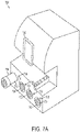
- FIGS. 7A and 7B illustrate the present disclosure.
- FIG. 7A illustrates an HPLC instrument 700 with docking stations 702 for container assemblies 704 containing fluid mediums.
- the HPLC instrument 700 has indicator lights 706 which can signal to a user the status of the fluid medium held within the related container assembly 704 secured within the adjacent docking station 702. For example, an indicator light 706 can provide an estimate of how much fluid medium volume is remaining in the related container assembly 704 based on the color of the indicator light.
- the HPLC instrument 700 can also have a user interface 708 for monitoring and interacting with the instrument.
- FIG. 7A further illustrates how a container assembly 704 may be horizontally mounted onto and coupled with an HPLC instrument 700.
- Solvents can be delivered according to operational pressures and requirements to the HPLC instrument 700 from a container assembly 704 in the illustrated horizontal or cantilevered orientation. In a horizontal or cantilever orientation, delivery of fluid medium to an instrument does not rely on gravity, thus allowing for the construction of fluidic instruments that do not require mounting fluid containers proximate to the top of the instrument.
- a barcode reader or QR-code reader may be connected to the HPLC instrument 700 and be coupled with a computer system in communication with the HPLC instrument 700 for data input.
- FIG. 7B is a cross-sectional illustration of a container assembly 704 that may couple with the HPLC instrument 700.
- the container assembly is made from an external container 710 which defines a first volume 712 and further holds an internal container 714.
- the internal container 714 defines a second volume 716, a volume that can hold solvent, and is fluidly sealed from the external container 710 and the first volume 712.
- An interface region 718 includes ports that fluidly connect the first volume 712 and the second volume 716 of the container assembly 704 to the appropriate systems of the HPLC instrument 700.
- the user handling region 720 is configured for a user to efficiently handle the container assembly 704.
- the external container 710 can have a generally rectangular profile.
- Computerized components that can operate to control the HPLC instrument can include a processing device which can be communicatively coupled to the memory device via a bus.
- the non-volatile memory device may include any type of memory device that retains stored information when powered off. Examples of the memory device include electrically erasable programmable read-only memory (“ROM”), flash memory, or any other type of non-volatile memory. At least some of the memory device can include a non-transitory medium / memory device from which the processing device can read instructions.
- a non-transitory computer-readable medium can include electronic, optical, magnetic, or other storage devices capable of providing the processing device with computer-readable instructions or other program code.
- Examples of a non-transitory computer-readable medium include magnetic disk(s), memory chip(s), ROM, random-access memory (“RAM”), an ASIC, a configured processor, optical storage, and/or any other medium from which a computer processor can read instructions.
- the instructions may include processor-specific instructions generated by a compiler and/or an interpreter from code written in any suitable computer-programming language, including, for example, C, C++, C#, Java, Python, Perl, and JavaScript.
Landscapes
- Physics & Mathematics (AREA)
- Immunology (AREA)
- General Physics & Mathematics (AREA)
- Chemical & Material Sciences (AREA)
- Analytical Chemistry (AREA)
- Pathology (AREA)
- General Health & Medical Sciences (AREA)
- Life Sciences & Earth Sciences (AREA)
- Health & Medical Sciences (AREA)
- Biochemistry (AREA)
- Engineering & Computer Science (AREA)
- Mechanical Engineering (AREA)
- Fluid Mechanics (AREA)
- Automatic Analysis And Handling Materials Therefor (AREA)
- Feeding, Discharge, Calcimining, Fusing, And Gas-Generation Devices (AREA)
- Sampling And Sample Adjustment (AREA)
- Containers And Packaging Bodies Having A Special Means To Remove Contents (AREA)
Description
- The present invention resides in the field of high-pressure, or high-performance, liquid chromatography (HPLC) assays, particularly for the delivery of reagents, diluents, solvents, and other fluids an HPLC instrument and apparatus system. More specifically, the present invention is directed to a fluid handling system for the delivery of solvent fluids with positive pressure to an HPLC instrument.
- HPLC is a chromatographic technique used to separate a mixture of compounds in analytical chemistry and biochemistry with the purpose of identifying, quantifying or purifying the individual components of the mixture. Generally, HPLC relies on pumps to pass a pressurized liquid and a sample mixture through a column filled with a sorbent, leading to the separation of the sample components. The active component of the column, the sorbent, is typically a granular material made of solid particles. The components of the sample mixture are separated from each other due to their different degrees of interaction with the sorbent particles. The pressurized liquid is typically a mixture of solvents (e.g. water, acetonitrile, methanol) and is referred to as "mobile phase". In addition to the composition and temperature of the mobile phase, the fluid pressure of the mobile phase plays a major role in the separation process by influencing the interactions taking place between sample components and sorbent. These interactions are physical in nature, such as hydrophobic (dispersive), dipole-dipole and ionic, most often a combination thereof.
- HPLC instruments and techniques have become increasingly sophisticated and complex, allowing for the analysis of multiple portions of a sample, utilizing a variety of different solvent fluids or analyzing a variety of samples with the same or different solvents. Such systems require fluid distribution systems capable of allocating precise amounts of solvents at specific pressures, for extended durations of time, and the ability to switch from one solvent to another.
- HPLC systems known in the field often require that the solvent fluids to be used by the instruments be elevated, so as to take advantage of gravity, drawing down the solvent fluids into the instrument, and thus priming the fluid lines of the HPLC instrument.
- In view of the above, there remains a need to provide solvents to HPLC instrumentation without the disadvantages noted above and known in the field.
-
US 8 387 817 B1 discloses a device for holding fluids in isolation, comprising an outer container and two deformable inner containers carried within the internal space of the outer container. Said device is intended to deliver fresh mobile phase in an HPLC instrument and remove used-up (waste) mobile phase therefrom. When the device is attached to the HPLC instrument, the mobile phase is suctioned from the bag by the HPLC instrument pump. - The aspects of the present invention are defined in the
independent claims 1, 3 and 8 attached. In a first aspect, the present invention provides the use of a container assembly for the delivery of a fluid medium, such as a solvent fluid, into a module of an HPLC instrument such as a pump set, a separation module, or a dilution module, the container assembly (being an array of bottles)comprising: an external container (hereinafter also referred to as "reagent box" "bottle" or "container") having a first port and a second port, the external container defining an interstitial volume fluidly connected to the first port; a compressible internal container contained within the external container and being fluidly sealed from the interstitial volume, the internal container holding the fluid medium and being fluidly connected to the second port by way of a valve; a sensor located outside of the external container, configured to determine an amount of the fluid medium held within the internal container; and a non-transitory computer-readable memory, located within the external container, that stores information regarding the volume and the age of the fluid medium held in the container assembly, wherein the non-transitory computer-readable memory is updatable to reflect decreases in the amount of fluid medium held in the container assembly. Each container assembly contains an enclosed internal container (hereinafter "bag" or "pouch"), within which solutions of solvents, reagents, buffers, diluents, and/or other fluid mediums are contained. The interstitial volume of space between the bag and the inside of the bottle is then pressurized with a gas, such as air. The increased gas pressure exerts force on the exterior of the bag, encouraging the egress of fluid medium, such as solvent fluid, from the enclosed bag through fluid connectors. The fluid connectors lead into the HPLC instrument and thus the present disclosure provides solvent fluids to an HPLC instrument at a positive pressure, relative to ambient conditions. - In some embodiments of the first aspect, the container assembly includes shut-off valves on the fluid connectors of the bottles to prevent fluid egress when the bottle is outside of or not properly coupled to an HPLC instrument. Shut-off connectors are also used on the HPLC instrument in order to prevent the aspiration of air by pumps if a bottle is not connected. Each bottle position on the HPLC instrument has an individual valve for pressurization and depressurization, which is fed from a centralized reservoir and releases to ambient atmosphere. In the case of a bag failure causing the volume of space in the bottle to fill with pressurized fluid, the valves vent away from the electronics within the HPLC instrument, into drip trays. The bottles may be made of metal, plastic, reinforced materials, or another appropriate rigid or semi-rigid materials, in order to generally maintain the form of the bottles when under pressure. In aspects, the structural walls of such bottle can restorably flex, expanding to a degree when under pressure and returning to a base, unexpanded state when not under pressure. A bottle may reside within an additional external housing, to assist in maintaining the form of and reinforce the bottles when under pressure.
- Further embodiments of the first aspect allow for providing fluid at a positive pressure to an HPLC instrument without the need for additional elevation in order to prime the system. The positive pressure also facilitates the use of a forward pressure degassing system, which requires no pump. The combination of positive pressure in the reagent consumable, coupled with the debubblers in the bulk fluids module of the present system, enables the consumables to be connected to the system easily without injecting bubbles of air into the fluidic system.
- Some embodiments of the first aspect comprise a container assembly for holding a fluid medium, the container assembly comprising: an external container having a first port and a second port, the external container defining a volume fluidly connected to the first port; and an internal container contained within the external container and being fluidly sealed from the volume, the internal container holding an fluid medium and being fluidly connected to the second port by way of a valve.
- The second aspect of the present invention is a method of handling fluid medium within an HPLC instrument, comprising: mounting an internal container within an external container, the external container defining an interstitial volume fluidly sealed from the internal container; holding the fluid medium within the internal container; coupling a first port of the external container to the interstitial volume and to a pressurization system of the instrument; coupling a second port of the external container to the internal container and to a module of the instrument; compressing the internal container by filling the interstitial volume with pressurized gas through the first port; delivering the fluid medium from within the internal container at a positive pressure to the instrument through the second port; and updating information regarding the amount of fluid medium held in the container assembly on a non-transitory computer-readable memory located within the external container.
- The third aspect of the present invention is a system for the handling of a fluid medium in an HPLC instrument, comprising: a gas intake and pressurization apparatus; a plurality of container assemblies, with each container assembly comprising an external container having a first port and a second port, each external container defining a first volume fluidly connected to the first port, and a compressible internal container defining a second volume contained within the external container and being fluidly sealed from the first volume, with each first volume being fluidly connected to the gas intake and pressurization apparatus, the internal container being fluidly connected to the second port by way of a valve, and with each second volume holding a fluid medium; a module of the HPLC instrument fluidly connected to each container assembly second volume, such that fluid medium from each container assembly can enter the instrument; and a non-transitory-computer-readable memory coupled to each of the plurality of container assemblies, wherein each non-transitory-computer-readable memory stores updatable information regarding the amount of the fluid medium held in the corresponding container assembly.
- It is to be noted that while the present invention is directed to HPLC instrumentation and chemistries, the pressurized system for the delivery of fluid medium can be used for any appropriately designed chemistry or biochemistry instrument that requires the pressurized delivery of reagents, buffers, diluents, solvents, or other fluid mediums.
- Illustrative aspects are described in detail below with reference to the following drawing figures.
-
FIG. 1 is an architectural schematic of the reagent box. -
FIG. 2 is an exploded-view illustration of the reagent box and its component parts. -
FIG. 3 depicts a design flowchart illustrating the interaction and connections between aspects of the bulk fluidics module. -
FIG. 4 is a detail schematic illustration of the consumable pressurization system. -
FIG. 5A is a cross-sections schematic illustration of a container assembly. -
FIG. 5B is a schematic illustration of the reagent consumable region, leak detection region, reagent decompression region, fluid combiner region, buffer conditioner, and diluent conditioner, and the fluid flow through these regions, within the bulk fluidics module. -
FIG. 6 is a schematic illustration of the waste handling assembly of the bulk fluidics module. -
FIG. 7A is an illustration of an HPLC instrument with container assemblies. -
FIG. 7B is an illustration of a container assembly, according to some embodiments. - Disclosed is a pressurized system for the delivery of fluid mediums into an HPLC instrument and system, wherein a bottle, or reagent box, is used to store and supply solvents. The reagent box is designed for simple and efficient loading and locking into an HPLC instrument, minimizing the time and work required to replenish reagents on an HPLC instrument. The reagent box may also improve the shelf life of the solvents stored within the reagent box.
- As used herein, the term "fluid medium" can refer to any one of a reagent solution, a buffer solution, a solvent, a diluent, a sample fluid (such as blood, urine, or other biological fluids), and/or other fluids. Such fluid mediums can be those that are used, or known in the art to be used, as part of a mobile phase in HPLC instrumentation. Alternatively, fluid mediums, and the pressurized delivery of fluid mediums, can be applied toward general life science or diagnostic research fluidic instrumentation, such as instrumentation for ion exchange chromatography, protein purification, solid phase extraction, liquid-liquid extraction, distillation, fractional distillation, fluid separation, magnetic separation, stripping, membrane or mesh filtration, flocculation, elutriation, leaching, or other such instrumentation. In particular, the fluid medium is an HPLC solvent, i.e. a fluid specific for use with HPLC instrumentation. The fluid medium can be a fluid used in separation techniques, filtration techniques, extraction techniques, purification techniques, distillation techniques, flocculation techniques, elution techniques, leaching techniques, or the like. Exemplary fluid mediums include, but are not limited to, water, acetic acid, acetone, acetonitrile, carbon disulphide, carbon tetrachloride, chlorobenzene, chloroform, cyclohexane, cyclopentane, dichloromethane, 1,2-dichloroethane, diethyl ether, dimethylformamide, dimethylsulfoxide, dioxan, ethanol, ethyl acetate, fluoroalkanes, heptane, hexane, methanol, methyl ethyl ketone, m-xylene, n-butyl acetate, n-butyl ether, nitromethane, n-methyl pyrollidone, pentane, petroleum ether, 1-propanol, 2-propanol, pyridine, tetrahydrofuran, toluene, triethylamine, 2,2,4-trimethylpentane, and combinations, mixtures, and variations thereof.
- The use of the reagent box further allows for easy identification of the reagent fluid contained within the bottle. This can be accomplished by color-coding the reagent box itself. In addition or alternatively, the reagent box can be barcoded, QR-coded, or otherwise labeled with identifying data. Further, the identity of an individual reagent box can be stored in a computerized database linked to a fluid instrument system, such as a HPLC system, so as to keep track of how much fluid medium has been dispensed from any given reagent box. Information regarding the content and/or volume of fluid medium remaining in a bottle can be disclosed to a user of an instrument by use of indicator lights. In aspects, such indicator lights can indicate that the amount of fluid medium remaining in a bottle is sufficient, that the amount of fluid medium remaining in a bottle is of concern, and/or that there is no fluid medium remaining in the bottle. Information regarding the content and/or volume of fluid medium remaining in a bottle, and also information regarding the number of tests run on an instrument with the bottles, can be stored, displayed, and/or manipulated on a computer system coupled with the fluid instrument system. A barcode reader or a QR-code reader may also be connected to a computer system coupled with a fluid instrument system and provide for data entry of the information barcoded or QR-coded on a reagent box.
- The external container (reagent box) includes a non-transitory computer-readable memory component that can store information regarding the volume of fluid medium held in the reagent box. The non-transitory computer-readable memory is updatable, such that as fluid medium decreases in the reagent box, the amount of remaining fluid medium in the box is updated to store information regarding the actual amount of fluid medium in the reagent box. Accordingly, if the reagent box is transferred from one fluid instrument system to a subsequent fluid instrument system, the subsequent fluid instrument system can obtain information regarding the amount of fluid medium in the reagent box from the non-transitory computer-readable memory component. In some aspects, the non-transitory computer-readable memory component can be updated using RF transmission from the fluid instrument system, for example, using RFID. In other aspects, the non-transitory computer-readable memory component can be electronically coupled to a fluid instrument system, and thereby updated, when the reagent box is mechanically coupled to the fluid instrument system.
- The container assembly, method and system also provides for the ability to change the buffer and reagents as the HPLC instrument is operating, i.e. on-the-fly, simply by swapping out reagent boxes. This can allow for a longer operation time of a fluidic instrument consuming fluid mediums, since reagent, solvent, diluent, and buffer fluids can be replenished as needed. When a reagent box is swapped out, air may fill the space between the fluid connections on the reagent box and the HPLC instrument. However, a debubbler, such as a porous membrane allows gas to pass through but not liquid, positioned on the HPLC side of the fluid connection can be used to prevent air bubbles or pockets from entering the fluidic system.
- This also provides for the advantage that the container assemblies can be loaded onto an HPLC instrument horizontally, in a cantilever orientation. This allows for an HPLC instrument configuration and design which does not require fluid mediums or other fluids to be at an elevated position on an instrument. This can provide for the delivery of fluid mediums at a positive pressure, thus removing the need to use gravity to draw down fluid medium fluids into the fluid lines of an instrument, e.g. in order to prime the lines of an instrument.
- While the bottles holding fluids are referred to herein as "reagent" boxes, it is to be understood that the fluid contents of a reagent box can include reagents, diluents, buffers, water, solvents, or any other appropriate fluid medium.
-
FIG. 1 is an architectural schematic of the reagent box and itscomponent parts 100. Thereagent box shell 110 of the reagent box can be made of metal, plastic, polymer, metal-reinforced polymer, or other appropriate materials that can both protect the contents in the interior of the reagent box and withstand stresses related to handling and storage. Accordingly, the reagent box can be rigid or semi-rigid, particularly when considered relative to afluid bag 102. The reagent box can be referred to as an external container. Thefluid bag 102 can be made of a flexible material that holds a fluid medium, and of a size that fits within the interior of thereagent box shell 110. The flexible material can be an elastic, an inelastic, or a semi-elastic polymer material. Furthermore, thefluid bag 102 can be referred to as an internal container. The interstitial volume 104 (alternatively referred to as a first volume), being the space in between the interior surface of thereagent box shell 110 and the exterior surface of thefluid bag 102, can be filled with a gas. A gas, such as air, can be pumped intointerstitial volume 104 through agas interface port 108. As gas fillsinterstitial volume 104 of a sealed reagent box, the pressure from the gas entering the volume of the reagent box can push fluid medium inside thefluid bag 102 out through any egress that exists in the reagent box, primarily through thefluid interface port 106. In some aspects, the volume of thefluid bag 102 can be referred to as second volume. Areagent box shell 110 can be sealed with areagent box cap 114 that fits over theopen end region 112 of thereagent box shell 110. Thereagent box cap 114 further includes afluid interface connector 116 which can couple to thefluid interface port 106, and agas interface connector 118 which can couple to thegas interface port 108. Thegas interface connector 118 when connected to thegas interface port 108 forms a pathway that allows for gas to be pumped into theinterstitial volume 104 of thereagent box shell 110. Thefluid interface connector 116 when connected to thefluid interface port 106 forms a pathway that allows for fluid to exit thefluid bag 102, which in operation is designed to be in response to the increased gas pressure of theinterstitial volume 104 pushing on the exterior surface of thefluid bag 102. Aninterface plate 120 surrounds and secures a cross-section of thefluid interface connector 116 andgas interface connector 118 to thefluid bag 102. -
FIG. 2 is an exploded-view illustration of thereagent box 200. Thereagent box shell 202, as noted above, can be made of materials that can both protect the contents in the interior of the reagent box and hold up to external stresses of handling and storage. Further, thereagent box shell 202 can be molded, contoured, or constructed in order to fit and interface with an HPLC instrument, or other fluidic instrument, as well as in order to be easily handled by a user. Thefluid bag 204, which can be made of any appropriate flexible material capable of holding fluid, can be shaped and/or contoured to fit within thereagent box shell 202. Thefluid bag 204 can be made of materials that are biologically inert and chemically inert, capable of withstanding the range of solvents, acids, bases, and other liquids that can have corrosive characteristics. Further, thefluid bag 204 can be shaped, tapered, and/or contoured to efficiently allow solvents to egress thefluid bag 204 through the fluid interface port 208 (alternatively referred to as a nozzle) when the exterior surface of thefluid bag 204 is under pressure. The shaping or tapering of thefluid bag 204 can mitigate against solvents being pushed to the sides, corners, or back of thefluid bag 204 when under pressure, by channeling or directing the held fluid medium toward the exit of thefluid bag 204 at thefluid interface port 208. The fluid medium accordingly exits thefluid bag 204 at a positive pressure. This can help to maximize the use of any fluid medium, reagent, buffer, diluent, or other solvent in afluid bag 204 and minimize the waste of any unused solvents. As shown, thefluid bag 204 is bordered by flat edging that causes thefluid bag 204 to substantively flatten under pressure. - The
reagent box cap 206 can be made of the same material or a different material as thereagent box shell 202. Thereagent box cap 206, when mechanically coupled with thereagent box shell 202, provides for a sealed (i.e. airtight) interstitial volume such that the gas in the volume between the interior surface of thereagent box shell 202 and the exterior surface of thefluid bag 204 will increase in pressure as more gas is pumped into volume. The seal between the coupledreagent box shell 202 andreagent box cap 206 should not break as gas pressure in the interstitial volume increases. Thereagent box cap 206 further includes agas interface port 214 for providing gas to the interstitial volume. A gas interface port O-ring 216 can be used to help secure thegas interface port 214 to a mechanical structure, such as a pipe or tube, used to channel gas into the reagent box. A fluid interface port O-ring 210 can be used to help secure thefluid interface port 208 as it mechanically couples with thereagent box cap 206, the reagentcap fluid port 220, andfluid interface connector 218. Aninterface connector latch 212 can be used to further secure the connection between thefluid interface connector 218 as it is seated within the reagentcap fluid port 220 and/or thefluid interface port 208. Thefluid interface port 208 can be threaded or otherwise molded to mechanically couple with the reagentcap fluid port 220, or to guide and control the flow of fluids that egress from thefluid bag 204. - In alternative embodiments, the reagent box or container assembly may not be built from a severable reagent box cap and reagent box shell. The reagent box can be constructed from parts that are permanently sealed together using methods known in the art. Alternatively, ports may be formed in a single body shell using methods known in the art, through which a fluid bag may be inserted and into which interface connections can be installed.
- The
reagent box shell 202 can further include alabel region 222 on which a barcode, QR-code, or other identifying marking can be printed or affixed. Alabel region 222 can be on any part of the external surface of thereagent box shell 202, as appropriate for handling and identifying the reagent box individually or coupled with an HPLC instrument. -
FIG. 3 is a design flowchart illustrating the interaction and connections between all components of thebulk fluidics module 300. Air (or in alternative embodiments, a gas from a controlled gas supply) is drawn into thebulk fluidics module 300 through theconsumable pressurization system 301. Theconsumable pressurization system 301 pressurizes the air and is sent to thereagent consumable region 302 throughpressurized gas channel 315, which can be a hollow piping, tubing, or the like. Air pressure sensors within theconsumable pressurization region 301 monitor the air pressure, sending that information to thecontrol electronics 306. Based on that pressure data, thecontrol electronics 306 send instructions to controllers within theconsumable pressurization region 301 to regulate the air pressure therein. Within thereagent consumable region 302 there are a plurality of reagent boxes, 302a, 302b, and 302d, which can contain fluids such as solvents, reagents, buffer, or diluent. The pressurized air delivered to thereagent consumable region 302 through thepressurized gas channel 315 is more specifically delivered into the gas receiving structure of each reagent box. As pressurized gas is pumped into the interstitial volume of a reagent box, fluid medium is pushed (at a positive pressure) out of the fluid bag inside the reagent box, out through theleak detection region 310 and into theconsumable decompression region 311. The fluid medium from each reagent box is pushed through a fluid channel dedicated that fluid medium. For example, as illustrated inFIG. 3 ,fluid channel 312 is dedicated to fluid medium from reagent box 302a,fluid channel 313 is dedicated to fluid medium from reagent box 302b, andfluid channel 314 is dedicated to fluid medium from reagent box 302d. However, there may be more than one reagent box connected to a fluid channel, such that multiple reagent boxes with the same fluid, i.e. the same reagent or the same buffer, can be provided to a single fluid channel system. - The
leak detection region 310 is designed to detect leaks from thereagent consumable region 302. Leaks detected from thereagent consumable region 302 will be sensed by sensors in theleak detection region 310, where the sensors can be thermal-based sensors, voltage-based sensors, current-based sensors, or the like. Upon detection of a leak, thecontrol electronics 306 can operate to trigger a warning indicator for a user, reduce or shut off pressurization of the reagent boxes, close valves, or execute other actions to minimize and/or stop further leakage. - The
consumable decompression region 311 includes valves that take in the fluid medium expelled from the related reagent boxes, and regulates the pressure of each fluid medium before further delivering said fluid mediums to the next stages of an HPLC instrument. From theconsumable decompression region 311, the fluid medium from reagent boxes which are reagents and buffers, such as 302a and 302b, are further directed to abuffer conditioner 304, and then further directed out of thebulk fluidics module 300, such as to a separation module of the HPLC instrument. Similarly, the fluid medium from reagent boxes which are diluents 302d are further directed from theconsumable decompression region 311 to adiluent conditioner 305, and then further directed out of thebulk fluidics module 300, such as to a dilution module of the HPLC instrument. - Following processing in the separation module and dilution module of the HPLC instrument, waste fluids from the HPLC instrument (i.e. solvents run through a sorbent column) are returned to the
bulk fluidics module 300, specifically to thewaste combiner subassembly 307. The waste fluids, once combined, can be further shunted to awaste container 308 as a separate section of the HPLC instrument and/or a waste pipe 309 leading out of the HPLC instrument entirely. -
FIG. 4 is a detailed schematic illustration of theconsumable pressurization system 400. In such system, air from the atmosphere is drawn into theconsumable pressurization system 400, and the HPLC instrument generally, through anair intake 402. Alternatively, the gas drawn into theconsumable pressurization system 400 may be from a controlled source of a specific gas, such as an inert gas. The air drawn into theconsumable pressurization system 400 then passes through anair filter 404 which filters out particulate matter, preventing such matter from entering theconsumable pressurization system 400. The filtered air then passes through theair pump 406 and through a check valve 408 (i.e. a one-way, non-return valve) into anair reservoir 410. A firstair pressure sensor 412, which may be a pressure gauge for 0.0-2.0 bar, or may be a pressure gauge for 0.0-4.0 bar, measures the air pressure in theair reservoir 410 and communicates that information to thecontrol electronics 306, to which theair pressure sensor 412 is electrically connected. - From the
air reservoir 410, the air drawn into theconsumable pressurization system 400 is directed into apressure regulator 414. Thepressure regulator 414 is controlled by apressure regulator controller 415, which is in turn electrically connected to thecontrol electronics 306. Thepressure regulator 414 compresses the air to a specified pressure and the pressurized air is measured by a secondair pressure sensor 416, which can be a pressure gauge for 0.0-1.0 bar, and which in other aspects can be a pressure gauge for 0.0-4.0 bar, which is also electrically connected to thecontrol electronics 306. Apressure switch 418, which closes an electrical circuit upon reaching a certain pressure, is also in contact with the pressurized. Upon reaching a pressure within a specific range, thepressure switch 418 can operate to, for example, open a pressure release valve, cause an indicator to communicate a signal, allow pressurized gas into thepressurized gas channel 315, and/or trigger other operations in thebulk fluidics module 300, or in the HPLC instrument generally. The pressurized air is then directed from theconsumable pressurization system 400 to the attached reagent boxes. -
FIG. 5A is a schematic illustration of acontainer assembly 500, which is also referred to as a reagent box. In embodiments, a pair of reagent boxes can be used for each fluid medium to be run through the HPLC instrument. Accordingly,FIG. 5A identifies constituent parts of the illustrated reagent box with two numbers which relate to a first and second reagent box, respectively, of a pair of reagent boxes containing the same solvent. Similarly, each element can be further defined with a suffix to identify whether a reagent, buffer, diluent, or other solvent is present in the reagent box, to allow for more precise tracking of fluid and connections in the present application. - In
FIG. 5A thereagent box shell 501/502 surrounds and defines an interstitial volume 503/504 that contains at least a fluid bag 505/506 (e.g. a reagent fluid bag 505a/506a or a diluent fluid bag 505d/506d) which can hold a fluid medium, such as an HPLC solvent. Pressurized gas 550 (such as air) is pumped from theconsumable pressurization system 400 though a gas delivery connector or interface on the instrument (not shown) and enters the interstitial volume 503/504 through the gas interface port 513/514 in the reagent box cap 511/512. As noted in embodiments above, the reagent box cap 511/512 operates as a lid that seals thereagent box shell 501/502 and only allows for the passage of gas through the gas interface port 513/514 and the passage of fluid through the fluid interface port 515/516. The lid can be detachable and reattachable to thereagent box shell 501/502. As pressurized gas fills the interstitial volume 503/504, the pressure on the exterior surface of the fluid bag 505/506 increases, reducing the volume of the interior of the fluid bag 505/506. The coupledreagent box shell 501/502 sealed with the reagent box cap 511/512 must be able to withstand the force exerted by the pressurized gas, retaining their seal. As the volume of the fluid bag 505/506 decreases, any fluid medium inside the fluid bag 505/506 accordingly exits the fluid bag 505/506 if possible, pushed out through the fluid interface port 515/516 at a positive pressure, which is also within the reagent box cap 511/512, as fluid stream 552/553 into and through a fluid receiving connector (not shown) on the instrument. The fluid interface port 515/516 may also include a shut-off valve, such that when the fluid interface port 515/516 is not coupled to an appropriate receiving connector, fluid medium inside the fluid bag 505/506 is prevented from egressing out of the fluid bag 505/506. If fluid medium from the fluid bag 505/506 exits into the interstitial volume 503/504, the shut-off valve can also operate to prevent leakage of the fluid medium out of thecontainer assembly 500. - The
pressurized gas 550 in the interstitial volume 503/504 can be pressurized to a pressure of about 0.5 bar, which can cause egress of fluid medium from the fluid bag 505/506 at a corresponding positive pressure. Alternatively, thepressurized gas 550 in the interstitial volume 503/504 can be pressurized to a pressure of about 1.0 bar, about 1.5 bar, about 2.0 bar, about 2.5 bar, about 3.0 bar, about 3.5 bar, or less than about 4.0 bar. Furthermore, thepressurized gas 550 in the interstitial volume 503/504 can be pressurized to a pressure in the range of about 0.5 bar to 4.0 bar. The coupledreagent box shell 501/502 sealed with the reagent box cap 511/512 must then be able to withstand the force exerted by thepressurized gas 550, retaining their seal. Thecontainer assembly 500 can be a semi-rigid container, such that the walls of thecontainer assembly 500 can bend or flex in response to the force exerted by thepressurized gas 550. - The
container assembly 500 further contains a consumable tag identifier 509/510, which can be a non-transitory computer-readable memory, located within thereagent box shell 501/502, which is electrically connected to thecontrol electronics 306 and identifies the contents of the particular reagent box connected to the HPLC instrument. The consumable tag identifier 509/510 may also include other information about the reagent box and the fluid medium contained within, such as the age of reagents or production information regarding the reagent box and/or its contents. The reagent box can further include aconsumable sensor 507/508, located outside of thereagent shell box 501/502, which is electrically connected to thecontrol electronics 306 and senses the amount of consumable solvent remaining within the fluid bag 505/506. The consumable tag identifier 509/510 can store information regarding the amount of fluid medium remaining in the fluid bag 505/506, which can be further updated by the HPLC instrument. The HPLC instrument can then calculate the amount of fluid medium remaining in the fluid bag 505/506 based on the amount of fluid medium sensed by the HPLC instrument entering thebulk fluidics module 300. The HPLC instrument can be informationally coupled to the consumable tag identifier 509/510, through RFID or other wireless connection, or through an electronic coupling, and update the information regarding the amount of fluid medium remaining in the fluid bag 505/506 as stored in the consumable tag identifier 509/510. - The information from either or both of the consumable tag identifier 509/510 and the
consumable sensor 507/508 is relayed to thecontrol electronics 306, and is used by thecontrol electronics 306 to regulate gas and fluid flow through thebulk fluidics module 300. When theconsumable sensor 507/508 or consumable tag identifier 509/510 communicates the amount of consumable fluid medium remaining within the fluid bag 505/506 to thecontrol electronics 306, thecontrol electronics 306 can further cause indicator lights (not shown) on the instrument to signal the status of the volume of fluid medium in thecontainer assembly 500. In some embodiments, thecontrol electronics 306 can indicate that the amount of fluid medium remaining is sufficient by triggering a green indicator light to illuminate, that the amount of fluid medium remaining is of concern by triggering a yellow indicator light to illuminate, and/or that there is no fluid medium remaining in the bottle by triggering a red indicator light source to illuminate. In aspects, any color indicator light can be used to indicate the various statuses of fluid medium in a container assembly. -
FIG. 5B is a schematic illustration of thereagent consumable region 520,leak detection region 522,reagent decompression region 528, fluid combiner region 538,buffer conditioner 542, anddiluent conditioner 544, and the fluid flow through these regions, within thebulk fluidics module 300. Thereagent consumable region 520 has a plurality ofcontainer assemblies 500, as illustrated inFIG. 5A , which can contain liquids such as reagents, buffers, and diluents. As described in relation toFIG. 5A , whenpressurized gas 550 from theconsumable pressurization system 400 enters the interstitial volume 503/504 of a reagent box, a fluid stream 552/553 egresses from the reagent box. In the illustration ofFIG. 5B , fluid stream 552a represents a flow of reagent fluid that egresses from a first reagent box containing that reagent. Fluid stream 553a represents a flow of reagent fluid that egresses from a second reagent box containing the same or a different reagent as the first reagent box containing reagent. Alternatively, a single reagent box containing a particular reagent, or a plurality of more than two reagent boxes can be used to deliver a particular reagent or reagents into an HPLC system. Fluid stream 552b represents a flow of buffer fluid that egresses from a first reagent box containing that buffer. Fluid stream 553b represents a flow of reagent fluid that egresses from a second reagent box containing the same or a different buffer as the first reagent box containing buffer. Alternatively, a single reagent box containing a particular buffer, or a plurality of more than two reagent boxes can be used to deliver a particular buffer or buffers into an HPLC system. Fluid stream 552d represents a flow of diluent fluid that egresses from a first reagent box containing that diluent. Fluid stream 553d represents a flow of diluent fluid that egresses from a second reagent box containing the same or a different diluent as the first reagent box containing diluent. Alternatively, a single reagent box containing a particular diluent, or a plurality of more than two reagent boxes can be used to deliver a particular diluent or diluents into an HPLC system. - The fluid streams from the reagent boxes each flow into and through the
leak detection region 522, wherein each type of fluid, reagent, buffer, and diluent, pass into and through a respective leak detection tray and leak detector. Specifically, reagent fluid streams 552a and 553a each pass through a region containing leak detection tray 524a, wherein any leakage of reagent fluid will be detected by leak detector 526a. Similarly, buffer fluid streams 552b and 553b each pass through a region containing leak detection tray 524b, wherein any leakage of buffer fluid will be detected by leak detector 526b. In the same manner, diluent fluid streams 552d and 553d each pass through a region containing leak detection tray 524d, wherein any leakage of diluent fluid will be detected by leak detector 526d. Each of leak detectors 526a, 526b, and 526d are electrically connected to thecontrol electronics 306 and/or a control system external to the bulk fluidics module. When a leak is detected, an error message can be sent to the control electronics, notifying the user of the HPLC instrument of the leak, continuing operation of the HPLC instrument under sub-optimal conditions, and/or ceasing operation of the HPLC instrument. In embodiments, the leak detection region includes shut-off valves (not shown) for each connection to a bottle such that if a leak is detected, the valves prevent further fluid from the bottle identified as leaking from entering the HPLC instrument. In other embodiments, there may be more than one leak detection tray and leak detector for each type of fluid run through the bulk fluidics module. - The fluid streams continue through the
leak detection region 522 and can pass through theconsumable decompression region 528. The valves in theconsumable decompression region 528 serve to decompress the pressure of the reagent boxes once fluids have been expelled from the reagent boxes which, due to being forced out of a fluid bag 505/506 bypressurized gas 550, may be deformed such that the walls of the external container are pressed and stuck in the region of the fluid interface due to the remaining high pressure gas in the interstitial volume of the reagent boxes. A plurality of decompression valves in theconsumable decompression region 528 can be in fluid communication with the interstitial volumes 503/504 of the reagent boxes and operate to release pressurized gas from thosecontainer assemblies 500. In particular, in the embodiment illustrated byFIG. 5B , consumable decompression valve 530a, which is controlled by consumable decompression controller 534a, and is electrically connected to thecontrol electronics 306, connects to a corresponding gas interface port of acontainer assembly 500 from which reagent fluid stream 552a flows. Similarly, consumable decompression valve 532a, which is controlled by reagent decompression controller 536a, and is electrically connected to thecontrol electronics 306, connects to a corresponding gas interface port of acontainer assembly 500 from which reagent fluid stream 553a flows. Next, consumable decompression valve 530b, which is controlled by consumable decompression controller 534b, and is electrically connected to thecontrol electronics 306, connects to a corresponding gas interface port of acontainer assembly 500 from which buffer fluid stream 552b flows. Similarly, consumable decompression valve 532a, which is controlled by consumable decompression controller 536a, and is electrically connected to thecontrol electronics 306, connects to a corresponding gas interface port of acontainer assembly 500 from which buffer stream 553b flows. Finally, consumable decompression valve 530d, which is controlled by consumable decompression controller 534d, is electrically connected to thecontrol electronics 306, connects to a corresponding gas interface port of acontainer assembly 500 from which diluent stream 552d flows. Similarly, consumable decompression valve 532d, which is controlled by consumable decompression controller 536d, and is electrically connected to thecontrol electronics 306, connects to a corresponding gas interface port of acontainer assembly 500 from which diluent stream 553d flows. Each of the consumable decompression controllers related to the various reagent, fluid, and diluent fluid sources are specifically connected to valve control circuitry within thecontrol electronics 306. - The fluid streams subsequently enter the fluid combiner region 538 wherein each of the reagent, buffer, and/or diluent fluid streams are combined with like fluids. Specifically, reagent fluid streams 552a and 553a both enter reagent combiner valve 540a, which mixes and combines the reagents from each fluid stream into a uniform fluid, and outputs the combined fluid as a single combined
reagent stream 554. Similarly, buffer fluid streams 552b and 553b both enter fluid combiner valve 540b, which mixes and combines the buffers from each fluid stream into a uniform fluid, and outputs the combined fluid as a single combinedbuffer stream 556. In the same manner, diluent fluid streams 552d and 553d both enter diluent combiner valve 540a, which mixes and combines the diluent from each fluid stream into a uniform fluid, and outputs the combined fluid as a single combineddiluent stream 554. Each of the reagent, fluid, and diluent combiner valves 540a, 540b, and 540d, are specifically connected to valve control circuitry within thecontrol electronics 306. - Combined
reagent stream 554 and combinedbuffer stream 556 are both directed from the fluid combiner region 538 intobuffer conditioner 542. Both the combinedreagent stream 554 and the combinedbuffer stream 556 are then directed from thebuffer conditioner 542 to the separation module of the HPLC instrument, wherein the streams may be divided and/or recombined during the HPLC process. - Combined
diluent stream 558 is directed from the fluid combiner region 538 intodiluent conditioner 544. The combineddiluent stream 558 is then directed from thediluent conditioner 544 to the diluent module of the HPLC instrument, wherein the stream may be divided and/or recombined during the HPLC process. - Alternatively, in an aspect not covered by the present invention, the roles of an interstitial volume and fluid bag in a reagent box can effectively be swapped. In particular, an interstitial volume can be filled with the fluid medium to provide to an instrument, and an internal container, such as gas bag, can be collapsed and empty when the interstitial volume is filled with a fluid medium. The gas bag can be connected to a consumable pressurization system outside of the reagent box through a gas interface port and filled with a gas, such as pressurized air. The interstitial volume can be fluidly connected to a fluid interface port, which can provide a flow path for the fluid medium in the interstitial volume to enter into an instrument. As pressurized gas fills the gas bag, the volume of the interstitial volume is reduced, thereby pushing fluid medium in the interstitial volume out through the egress of the fluid interface port. The gas interface port with the gas bag can be arranged on a side of the reagent box distal from the fluid interface port. Furthermore, filling the gas bag from the back of the reagent box forward can cause the fluid medium to advance toward the fluid interface port. Finally, the interior structure of the reagent box shell can be shaped to channel or direct fluid medium toward a fluid interface port.
-
FIG. 6 is a schematic illustration of thewaste handling assembly 600 of thebulk fluidics module 300. Following operational use in the HPLC instrument, waste fluids are returned to the bulk fluidics module, and specifically to the waste combiner, valve, andport subassembly 602. The waste combiner, valve, andport subassembly 602 is centered around a waste combiner andvalve region 614, which is composed of awaste fluid reservoir 615 and awaste combiner valve 616.Waste diluent fluid 610 is sent to thewaste fluid reservoir 615 from the HPLC dilution module. Similarly, waste reagent andbuffer fluids 612 are sent to thewaste fluid reservoir 615 from the HPLC separation module. Thewaste fluid container 615 has anair intake 608 to provide atmospheric air pressure so that the combinedwaste fluid 613 smoothly will move through the waste combiner, valve, andport subassembly 602. The waste combiner, valve, andport subassembly 602 further includes awaste backup sensor 618 and aback pressure regulator 620. Thewaste backup sensor 618, which is connected to the waste data handling circuitry ofcontrol electronics 306, detects when the combinedwaste fluid 613 has filled thewaste fluid reservoir 615 to a maximum tolerated volume. Theback pressure regulator 620 which is connected to a detection module of the HPLC instrument external to thebulk fluidics module 300, controls the amount ofwaste fluids port subassembly 602. The combinedwaste fluid 613 is directed from thewaste fluid reservoir 615 into thewaste combiner valve 616 and is further directed to either thewaste container region 604 and/or thewaste pipe region 606. - Combined
waste fluid 613 is directed from thewaste combiner valve 616 to either a waste container port 624a or a waste pipe port 628a. Combined waste fluid that is directed to waste container port 624a passes through said port, and through the waste container receiver 624b, intowaste container 630. A waste container sensor is made up from a first waste container sensor component 622a within the waste combiner, valve, andport subassembly 602, a second waste container sensor component 622b external to but in contact with the waste container, and a third waste container sensor component 622c inside the waste container. The first waste container sensor component 622a is electrically connected to the waste data handling circuitry ofcontrol electronics 306, and detects when the amount fluid in thewaste container 630 reaches a maximum tolerated volume. Combined waste fluid that is directed to waste pipe port 628a passes through said port, and through the waste pipe receiver 628b, intowaste pipe 632 which leads outside the HPLC instrument, ideally to a proper waste disposal system. A waste pipe sensor is made up from a first waste pipe sensor component 626a within the waste combiner, valve, andport subassembly 602 and a second waste pipe sensor component 626b which is in contact with the waste pipe. The first waste pipe sensor component 626a is electrically connected to the waste data handling circuitry ofcontrol electronics 306, and monitors the flow of waste exiting thebulk fluidics module 300. -
FIGS. 7A and7B illustrate the present disclosure.FIG. 7A illustrates anHPLC instrument 700 withdocking stations 702 forcontainer assemblies 704 containing fluid mediums. TheHPLC instrument 700 hasindicator lights 706 which can signal to a user the status of the fluid medium held within therelated container assembly 704 secured within theadjacent docking station 702. For example, anindicator light 706 can provide an estimate of how much fluid medium volume is remaining in therelated container assembly 704 based on the color of the indicator light. TheHPLC instrument 700 can also have auser interface 708 for monitoring and interacting with the instrument.FIG. 7A further illustrates how acontainer assembly 704 may be horizontally mounted onto and coupled with anHPLC instrument 700. Solvents can be delivered according to operational pressures and requirements to theHPLC instrument 700 from acontainer assembly 704 in the illustrated horizontal or cantilevered orientation. In a horizontal or cantilever orientation, delivery of fluid medium to an instrument does not rely on gravity, thus allowing for the construction of fluidic instruments that do not require mounting fluid containers proximate to the top of the instrument. A barcode reader or QR-code reader (not shown) may be connected to theHPLC instrument 700 and be coupled with a computer system in communication with theHPLC instrument 700 for data input. -
FIG. 7B is a cross-sectional illustration of acontainer assembly 704 that may couple with theHPLC instrument 700. The container assembly is made from anexternal container 710 which defines afirst volume 712 and further holds aninternal container 714. Theinternal container 714 defines asecond volume 716, a volume that can hold solvent, and is fluidly sealed from theexternal container 710 and thefirst volume 712. Aninterface region 718 includes ports that fluidly connect thefirst volume 712 and thesecond volume 716 of thecontainer assembly 704 to the appropriate systems of theHPLC instrument 700. Theuser handling region 720 is configured for a user to efficiently handle thecontainer assembly 704. In aspects, theexternal container 710 can have a generally rectangular profile. - Computerized components that can operate to control the HPLC instrument can include a processing device which can be communicatively coupled to the memory device via a bus. The non-volatile memory device may include any type of memory device that retains stored information when powered off. Examples of the memory device include electrically erasable programmable read-only memory ("ROM"), flash memory, or any other type of non-volatile memory. At least some of the memory device can include a non-transitory medium / memory device from which the processing device can read instructions. A non-transitory computer-readable medium can include electronic, optical, magnetic, or other storage devices capable of providing the processing device with computer-readable instructions or other program code. Examples of a non-transitory computer-readable medium include magnetic disk(s), memory chip(s), ROM, random-access memory ("RAM"), an ASIC, a configured processor, optical storage, and/or any other medium from which a computer processor can read instructions. The instructions may include processor-specific instructions generated by a compiler and/or an interpreter from code written in any suitable computer-programming language, including, for example, C, C++, C#, Java, Python, Perl, and JavaScript.
Claims (12)
- The use of a container assembly for delivering a fluid medium into a module of an HPLC instrument, the container assembly comprising:an external container having a first port and a second port, the external container defining an interstitial volume fluidly connected to the first port; anda compressible internal container contained within the external container and being fluidly sealed from the interstitial volume, the internal container holding the fluid medium and being fluidly connected to the second port by way of a valve;a sensor located outside of the external container, configured to determine an amount of the fluid medium held within the internal container; anda non-transitory computer-readable memory, located within the external container, that stores information regarding the volume and the age of the fluid medium held in the container assembly, wherein the non-transitory computer-readable memory is updatable to reflect decreases in the amount of fluid medium held in the container assembly.
- The use according to claim 1, wherein(i) the internal container is configured to channel fluid medium toward the second port; or(ii) the valve prevents the egress of fluid medium when the container assembly is not connected to an instrument; or(iii) the container assembly further comprises a detachable lid.
- A method of handling fluid medium within an HPLC instrument, comprising:mounting an internal container within an external container, the external container defining an interstitial volume fluidly sealed from the internal container;holding the fluid medium within the internal container;coupling a first port of the external container to the interstitial volume and to a pressurization system of the instrument;coupling a second port of the external container to the internal container and to a module of the instrument;compressing the internal container by filling the interstitial volume with pressurized gas through the first port;delivering the fluid medium from within the internal container at a positive pressure to the instrument through the second port; andupdating information regarding the amount of fluid medium held in the container assembly on a non-transitory computer-readable memory located within the external container.
- The method of handling fluid medium according to claim 3, further comprising drawing atmospheric air into the pressurization system.
- The method of handling fluid medium according to claim 3, wherein the gas is pressurized to a pressure in the range of 0.5 to 4.0 bar.
- The method of handling fluid medium according to claim 3, further comprising, after delivering the fluid medium, depressurizing the interstitial volume of the external container.
- The method of handling fluid medium according to claim 3, further comprising monitoring the amount of fluid medium held within the internal container.
- A system for the handling of a fluid medium in an HPLC instrument, comprising:a gas intake and pressurization apparatus;a plurality of container assemblies, with each container assembly comprising an external container having a first port and a second port, each external container defining a first volume fluidly connected to the first port, and a compressible internal container defining a second volume contained within the external container and being fluidly sealed from the first volume, with each first volume being fluidly connected to the gas intake and pressurization apparatus, the internal container being fluidly connected to the second port by way of a valve, and with each second volume holding a fluid medium;a module of the HPLC instrument fluidly connected to each container assembly second volume, such that fluid medium from each container assembly can enter the instrument; anda non-transitory-computer-readable memory coupled to each of the plurality of container assemblies, wherein each non-transitory-computer-readable memory stores updatable information regarding the amount of the fluid medium held in the corresponding container assembly.
- The system according to claim 8, wherein(i) the gas intake and pressurization apparatus draws atmospheric air into the pressurization system; optionally wherein(ii) the gas is pressurized to a pressure in the range of 0.5 to 4.0 bar.
- The system according to claim 8, wherein the instrument further comprises(i) a plurality of sensors that monitor the amount of fluid medium held within the plurality of container assemblies; or(ii) sensors that monitor for leaks from the container assemblies.
- The system according to claim 8, wherein the instrument further comprises depressurization valves operative to decrease a gas pressure in the first volume.
- The system according to claim 8, further wherein a status indicating a volume of fluid within a fluid container is communicated to a user by use of indicator lights on the instrument.
Priority Applications (1)
| Application Number | Priority Date | Filing Date | Title |
|---|---|---|---|
| EP22201389.8A EP4137812A1 (en) | 2013-03-14 | 2014-03-14 | Bottle pressurization delivery system |
Applications Claiming Priority (2)
| Application Number | Priority Date | Filing Date | Title |
|---|---|---|---|
| US201361785000P | 2013-03-14 | 2013-03-14 | |
| PCT/US2014/028981 WO2014153081A1 (en) | 2013-03-14 | 2014-03-14 | Bottle pressurization delivery system |
Related Child Applications (1)
| Application Number | Title | Priority Date | Filing Date |
|---|---|---|---|
| EP22201389.8A Division EP4137812A1 (en) | 2013-03-14 | 2014-03-14 | Bottle pressurization delivery system |
Publications (3)
| Publication Number | Publication Date |
|---|---|
| EP2969096A1 EP2969096A1 (en) | 2016-01-20 |
| EP2969096A4 EP2969096A4 (en) | 2016-11-23 |
| EP2969096B1 true EP2969096B1 (en) | 2022-11-16 |
Family
ID=51522065
Family Applications (2)
| Application Number | Title | Priority Date | Filing Date |
|---|---|---|---|
| EP22201389.8A Pending EP4137812A1 (en) | 2013-03-14 | 2014-03-14 | Bottle pressurization delivery system |
| EP14767684.5A Active EP2969096B1 (en) | 2013-03-14 | 2014-03-14 | Bottle pressurization delivery system |
Family Applications Before (1)
| Application Number | Title | Priority Date | Filing Date |
|---|---|---|---|
| EP22201389.8A Pending EP4137812A1 (en) | 2013-03-14 | 2014-03-14 | Bottle pressurization delivery system |
Country Status (6)
| Country | Link |
|---|---|
| US (3) | US9921193B2 (en) |
| EP (2) | EP4137812A1 (en) |
| CN (1) | CN105188871B (en) |
| AU (2) | AU2014236334B2 (en) |
| HK (1) | HK1214198A1 (en) |
| WO (1) | WO2014153081A1 (en) |
Families Citing this family (8)
| Publication number | Priority date | Publication date | Assignee | Title |
|---|---|---|---|---|
| WO2014153081A1 (en) * | 2013-03-14 | 2014-09-25 | Bio-Rad Laboratories, Inc. | Bottle pressurization delivery system |
| EP3257783A1 (en) * | 2016-06-14 | 2017-12-20 | Diatron MI ZRT. | Reagent pack with integrated waste reservoir |
| US10995740B2 (en) * | 2016-09-26 | 2021-05-04 | Shimadzu Corporation | Switching valve, binary pump, and liquid chromatograph with binary pump |
| FR3074069A1 (en) * | 2017-11-28 | 2019-05-31 | Commissariat A L'energie Atomique Et Aux Energies Alternatives | DEVICE FOR INJECTING A FLUID SAMPLE |
| KR102069868B1 (en) * | 2018-02-28 | 2020-01-23 | 고려대학교 산학협력단 | Metabolome sampling and analytical method specific for metabolite analysis of synthetic gas fermenting microorganisms during synthesis gas fermentation |
| CN109444218B (en) * | 2018-12-17 | 2024-02-20 | 西南科技大学 | Improved environment state simulation device in oxidation kinetics reaction and use method |
| EP3804855A1 (en) * | 2019-10-07 | 2021-04-14 | Bio-Rad Europe GmbH | Fluid container device comprising a septum member, and method of delivering fluid from such a device |
| GB2609494A (en) | 2021-08-06 | 2023-02-08 | Agilent Technologies Inc | Solvent channel identification |
Citations (1)
| Publication number | Priority date | Publication date | Assignee | Title |
|---|---|---|---|---|
| US20130056112A1 (en) * | 2005-04-25 | 2013-03-07 | Advanced Technology Materials, Inc. | Liner-based liquid storage and dispensing systems with empty detection capability |
Family Cites Families (23)
| Publication number | Priority date | Publication date | Assignee | Title |
|---|---|---|---|---|
| US4448684A (en) * | 1983-01-28 | 1984-05-15 | The Perkin-Elmer Corporation | Solvent pressurization system |
| US4541452A (en) * | 1984-10-10 | 1985-09-17 | The Perkin-Elmer Corporation | Solvent pressurization system |
| DE3924589C1 (en) * | 1989-07-25 | 1990-12-20 | Bosch-Siemens Hausgeraete Gmbh, 8000 Muenchen, De | |
| US4994180A (en) | 1990-02-01 | 1991-02-19 | Systec, Inc. | Solvent handling system |
| US5415033A (en) * | 1990-08-30 | 1995-05-16 | Vista Research, Inc. | Simplified apparatus for detection of leaks in pressurized pipelines |
| US5242586A (en) * | 1990-12-17 | 1993-09-07 | Biotage Inc. | Column protection system for liquid chromatography system |
| US5352585A (en) * | 1993-06-29 | 1994-10-04 | Bio-Rad Laboratories, Inc. | System for benzodiazepine detection |
| JP2824443B2 (en) * | 1994-05-12 | 1998-11-11 | ティ・エフ・シィ株式会社 | Preparative liquid chromatography equipment |
| JP3929000B2 (en) * | 1998-05-08 | 2007-06-13 | アイセロ化学株式会社 | Container for high-purity chemical liquid |
| TW442429B (en) | 1998-05-08 | 2001-06-23 | Aicello Chemical Co | Container for high purity liquid chemicals |
| US6296771B1 (en) | 1999-04-02 | 2001-10-02 | Symyx Technologies, Inc. | Parallel high-performance liquid chromatography with serial injection |
| US7204679B2 (en) * | 2002-09-30 | 2007-04-17 | Emerson Electric Co. | Flow control system |
| KR101085897B1 (en) * | 2005-01-03 | 2011-11-23 | 삼성전자주식회사 | Refrigerator and method of controlling the same |
| KR100997506B1 (en) * | 2006-06-13 | 2010-12-01 | 어드밴스드 테크놀러지 머티리얼즈, 인코포레이티드 | Liquid dispensing systems encompassing gas removal |
| DE102007050573A1 (en) | 2007-10-23 | 2009-04-30 | Evonik Degussa Gmbh | Large containers for handling and transporting high purity and ultrapure chemicals |
| US7752890B2 (en) * | 2007-11-08 | 2010-07-13 | Battelle Memorial Institute | Method and apparatus for continuous fluid leak monitoring and detection in analytical instruments and instrument systems |
| US8308854B2 (en) * | 2009-12-15 | 2012-11-13 | Thermo Finnigan Llc | Helium reclamation systems and methods for a gas chromatograph |
| KR20120101173A (en) * | 2010-01-06 | 2012-09-12 | 어드밴스드 테크놀러지 머티리얼즈, 인코포레이티드 | Liquid dispensing systems with gas removal and sensing capabilities |
| EP2606345B1 (en) * | 2010-08-17 | 2014-11-19 | Grünenthal GmbH | Method and device for supplying liquids to analysis units and liquid handling systems |
| US10463988B2 (en) | 2010-09-23 | 2019-11-05 | Ge Healthcare Bio-Sciences Corp. | Single use slurrying and chromatography systems |
| CN103189119B (en) | 2010-10-29 | 2015-05-27 | 赛默菲尼根有限责任公司 | Method and system for liquid chromatograph with compressibility and viscosity monitoring to identify fluids |
| US8387817B1 (en) | 2011-11-18 | 2013-03-05 | Sielc Technologies Corporation | Container for holding multiple fluids in isolation |
| WO2014153081A1 (en) * | 2013-03-14 | 2014-09-25 | Bio-Rad Laboratories, Inc. | Bottle pressurization delivery system |
-
2014
- 2014-03-14 WO PCT/US2014/028981 patent/WO2014153081A1/en active Application Filing
- 2014-03-14 EP EP22201389.8A patent/EP4137812A1/en active Pending
- 2014-03-14 EP EP14767684.5A patent/EP2969096B1/en active Active
- 2014-03-14 AU AU2014236334A patent/AU2014236334B2/en not_active Ceased
- 2014-03-14 US US14/213,001 patent/US9921193B2/en active Active
- 2014-03-14 CN CN201480015053.9A patent/CN105188871B/en active Active
-
2016
- 2016-02-25 HK HK16102190.6A patent/HK1214198A1/en not_active IP Right Cessation
-
2018
- 2018-01-31 US US15/885,555 patent/US11525813B2/en active Active
- 2018-07-03 AU AU2018204839A patent/AU2018204839B2/en not_active Ceased
-
2022
- 2022-12-09 US US18/078,751 patent/US20230103942A1/en active Pending
Patent Citations (1)
| Publication number | Priority date | Publication date | Assignee | Title |
|---|---|---|---|---|
| US20130056112A1 (en) * | 2005-04-25 | 2013-03-07 | Advanced Technology Materials, Inc. | Liner-based liquid storage and dispensing systems with empty detection capability |
Also Published As
| Publication number | Publication date |
|---|---|
| EP2969096A4 (en) | 2016-11-23 |
| AU2018204839B2 (en) | 2020-02-27 |
| AU2014236334A1 (en) | 2015-09-03 |
| US20230103942A1 (en) | 2023-04-06 |
| EP2969096A1 (en) | 2016-01-20 |
| US20140261868A1 (en) | 2014-09-18 |
| US11525813B2 (en) | 2022-12-13 |
| AU2014236334B2 (en) | 2018-04-05 |
| EP4137812A1 (en) | 2023-02-22 |
| CN105188871A (en) | 2015-12-23 |
| US9921193B2 (en) | 2018-03-20 |
| CN105188871B (en) | 2018-01-12 |
| HK1214198A1 (en) | 2016-07-22 |
| WO2014153081A1 (en) | 2014-09-25 |
| AU2018204839A1 (en) | 2018-07-19 |
| US20180238839A1 (en) | 2018-08-23 |
Similar Documents
| Publication | Publication Date | Title |
|---|---|---|
| AU2018204839B2 (en) | Bottle pressurization delivery system | |
| CN111132724B (en) | Vacuum liquid extraction and purification system and method | |
| US9421542B2 (en) | System for treating liquids | |
| US20120195799A1 (en) | Process analyzer | |
| JP2009519440A (en) | Single-use manifold and sensor for automatic aseptic transfer of solutions in biological processing applications | |
| WO2013008502A1 (en) | Solid phase extraction device and viscosity measurement device | |
| US20140158615A1 (en) | Prefilled liquid cartridge for the supply of a sample separation device with an operating liquid | |
| US8371181B2 (en) | Continuous flow pump | |
| US10241124B2 (en) | Method to perform a measurement of an analyte in a sample using an automatic analyzer | |
| CN102171560B (en) | Analyzing device and method for controlling same | |
| EP2847598B1 (en) | Cartridge for dispensing a fluid comprising a reagent | |
| CN102171561A (en) | Analyzing device | |
| US11219867B2 (en) | Single-use filtering module and single-use cleaning module, each insertable in a modular filtering system | |
| JP2007232524A (en) | Method and device for filtrating solution of protein or like | |
| US20240210364A1 (en) | Liquid Chromatograph and Liquid Delivery Method | |
| JP5039456B2 (en) | Liquid chromatograph analyzer | |
| KR102124589B1 (en) | Apparatus for testing sensor | |
| US20240201144A1 (en) | Liquid chromatograph and method for controlling same | |
| US20240050954A1 (en) | Fluid container device comprising a septum member, and method of delivering fluid from such a device | |
| KR102720793B1 (en) | Sequencing device | |
| KR20230150261A (en) | Chemical processing systems and equipment | |
| KR101098960B1 (en) | Method for pollutant detecting using liquid photoreactor and system thereof |
Legal Events
| Date | Code | Title | Description |
|---|---|---|---|
| PUAI | Public reference made under article 153(3) epc to a published international application that has entered the european phase |
Free format text: ORIGINAL CODE: 0009012 |
|
| 17P | Request for examination filed |
Effective date: 20150811 |
|
| AK | Designated contracting states |
Kind code of ref document: A1 Designated state(s): AL AT BE BG CH CY CZ DE DK EE ES FI FR GB GR HR HU IE IS IT LI LT LU LV MC MK MT NL NO PL PT RO RS SE SI SK SM TR |
|
| AX | Request for extension of the european patent |
Extension state: BA ME |
|
| RIN1 | Information on inventor provided before grant (corrected) |
Inventor name: MAINWARING-BURTON, WILLIAM Inventor name: WRENCH, NATHAN Inventor name: HARRISON, NICK Inventor name: BUTCHER, CHRIS |
|
| RIN1 | Information on inventor provided before grant (corrected) |
Inventor name: BUTCHER, CHRIS Inventor name: MAINWARING-BURTON, WILLIAM Inventor name: WRENCH, NATHAN Inventor name: HARRISON, NICK |
|
| DAX | Request for extension of the european patent (deleted) | ||
| A4 | Supplementary search report drawn up and despatched |
Effective date: 20161021 |
|
| RIC1 | Information provided on ipc code assigned before grant |
Ipc: G01N 30/88 20060101ALI20161017BHEP Ipc: G01N 30/22 20060101ALI20161017BHEP Ipc: B67D 7/02 20100101ALI20161017BHEP Ipc: G01N 1/14 20060101ALI20161017BHEP Ipc: B65D 77/06 20060101ALI20161017BHEP Ipc: B65D 83/00 20060101ALI20161017BHEP Ipc: G01N 35/10 20060101ALI20161017BHEP Ipc: G01N 30/16 20060101ALI20161017BHEP Ipc: C02F 1/28 20060101ALI20161017BHEP Ipc: B65D 1/24 20060101ALI20161017BHEP Ipc: B01D 15/08 20060101AFI20161017BHEP |
|
| STAA | Information on the status of an ep patent application or granted ep patent |
Free format text: STATUS: EXAMINATION IS IN PROGRESS |
|
| 17Q | First examination report despatched |
Effective date: 20190114 |
|
| STAA | Information on the status of an ep patent application or granted ep patent |
Free format text: STATUS: EXAMINATION IS IN PROGRESS |
|
| RAP3 | Party data changed (applicant data changed or rights of an application transferred) |
Owner name: BIO-RAD LABORATORIES, INC. |
|
| STAA | Information on the status of an ep patent application or granted ep patent |
Free format text: STATUS: EXAMINATION IS IN PROGRESS |
|
| GRAP | Despatch of communication of intention to grant a patent |
Free format text: ORIGINAL CODE: EPIDOSNIGR1 |
|
| STAA | Information on the status of an ep patent application or granted ep patent |
Free format text: STATUS: GRANT OF PATENT IS INTENDED |
|
| INTG | Intention to grant announced |
Effective date: 20220601 |
|
| GRAS | Grant fee paid |
Free format text: ORIGINAL CODE: EPIDOSNIGR3 |
|
| GRAA | (expected) grant |
Free format text: ORIGINAL CODE: 0009210 |
|
| STAA | Information on the status of an ep patent application or granted ep patent |
Free format text: STATUS: THE PATENT HAS BEEN GRANTED |
|
| AK | Designated contracting states |
Kind code of ref document: B1 Designated state(s): AL AT BE BG CH CY CZ DE DK EE ES FI FR GB GR HR HU IE IS IT LI LT LU LV MC MK MT NL NO PL PT RO RS SE SI SK SM TR |
|
| REG | Reference to a national code |
Ref country code: GB Ref legal event code: FG4D |
|
| REG | Reference to a national code |
Ref country code: CH Ref legal event code: EP |
|
| REG | Reference to a national code |
Ref country code: DE Ref legal event code: R096 Ref document number: 602014085549 Country of ref document: DE |
|
| REG | Reference to a national code |
Ref country code: IE Ref legal event code: FG4D |
|
| REG | Reference to a national code |
Ref country code: AT Ref legal event code: REF Ref document number: 1531425 Country of ref document: AT Kind code of ref document: T Effective date: 20221215 |
|
| REG | Reference to a national code |
Ref country code: LT Ref legal event code: MG9D |
|
| REG | Reference to a national code |
Ref country code: NL Ref legal event code: MP Effective date: 20221116 |
|
| REG | Reference to a national code |
Ref country code: AT Ref legal event code: MK05 Ref document number: 1531425 Country of ref document: AT Kind code of ref document: T Effective date: 20221116 |
|
| PG25 | Lapsed in a contracting state [announced via postgrant information from national office to epo] |
Ref country code: SE Free format text: LAPSE BECAUSE OF FAILURE TO SUBMIT A TRANSLATION OF THE DESCRIPTION OR TO PAY THE FEE WITHIN THE PRESCRIBED TIME-LIMIT Effective date: 20221116 Ref country code: PT Free format text: LAPSE BECAUSE OF FAILURE TO SUBMIT A TRANSLATION OF THE DESCRIPTION OR TO PAY THE FEE WITHIN THE PRESCRIBED TIME-LIMIT Effective date: 20230316 Ref country code: NO Free format text: LAPSE BECAUSE OF FAILURE TO SUBMIT A TRANSLATION OF THE DESCRIPTION OR TO PAY THE FEE WITHIN THE PRESCRIBED TIME-LIMIT Effective date: 20230216 Ref country code: LT Free format text: LAPSE BECAUSE OF FAILURE TO SUBMIT A TRANSLATION OF THE DESCRIPTION OR TO PAY THE FEE WITHIN THE PRESCRIBED TIME-LIMIT Effective date: 20221116 Ref country code: FI Free format text: LAPSE BECAUSE OF FAILURE TO SUBMIT A TRANSLATION OF THE DESCRIPTION OR TO PAY THE FEE WITHIN THE PRESCRIBED TIME-LIMIT Effective date: 20221116 Ref country code: ES Free format text: LAPSE BECAUSE OF FAILURE TO SUBMIT A TRANSLATION OF THE DESCRIPTION OR TO PAY THE FEE WITHIN THE PRESCRIBED TIME-LIMIT Effective date: 20221116 Ref country code: AT Free format text: LAPSE BECAUSE OF FAILURE TO SUBMIT A TRANSLATION OF THE DESCRIPTION OR TO PAY THE FEE WITHIN THE PRESCRIBED TIME-LIMIT Effective date: 20221116 |
|
| PG25 | Lapsed in a contracting state [announced via postgrant information from national office to epo] |
Ref country code: RS Free format text: LAPSE BECAUSE OF FAILURE TO SUBMIT A TRANSLATION OF THE DESCRIPTION OR TO PAY THE FEE WITHIN THE PRESCRIBED TIME-LIMIT Effective date: 20221116 Ref country code: PL Free format text: LAPSE BECAUSE OF FAILURE TO SUBMIT A TRANSLATION OF THE DESCRIPTION OR TO PAY THE FEE WITHIN THE PRESCRIBED TIME-LIMIT Effective date: 20221116 Ref country code: LV Free format text: LAPSE BECAUSE OF FAILURE TO SUBMIT A TRANSLATION OF THE DESCRIPTION OR TO PAY THE FEE WITHIN THE PRESCRIBED TIME-LIMIT Effective date: 20221116 Ref country code: IS Free format text: LAPSE BECAUSE OF FAILURE TO SUBMIT A TRANSLATION OF THE DESCRIPTION OR TO PAY THE FEE WITHIN THE PRESCRIBED TIME-LIMIT Effective date: 20230316 Ref country code: HR Free format text: LAPSE BECAUSE OF FAILURE TO SUBMIT A TRANSLATION OF THE DESCRIPTION OR TO PAY THE FEE WITHIN THE PRESCRIBED TIME-LIMIT Effective date: 20221116 Ref country code: GR Free format text: LAPSE BECAUSE OF FAILURE TO SUBMIT A TRANSLATION OF THE DESCRIPTION OR TO PAY THE FEE WITHIN THE PRESCRIBED TIME-LIMIT Effective date: 20230217 |
|
| PGFP | Annual fee paid to national office [announced via postgrant information from national office to epo] |
Ref country code: GB Payment date: 20230321 Year of fee payment: 10 Ref country code: DE Payment date: 20230328 Year of fee payment: 10 |
|
| P01 | Opt-out of the competence of the unified patent court (upc) registered |
Effective date: 20230510 |
|
| PG25 | Lapsed in a contracting state [announced via postgrant information from national office to epo] |
Ref country code: NL Free format text: LAPSE BECAUSE OF FAILURE TO SUBMIT A TRANSLATION OF THE DESCRIPTION OR TO PAY THE FEE WITHIN THE PRESCRIBED TIME-LIMIT Effective date: 20221116 |
|
| PG25 | Lapsed in a contracting state [announced via postgrant information from national office to epo] |
Ref country code: SM Free format text: LAPSE BECAUSE OF FAILURE TO SUBMIT A TRANSLATION OF THE DESCRIPTION OR TO PAY THE FEE WITHIN THE PRESCRIBED TIME-LIMIT Effective date: 20221116 Ref country code: RO Free format text: LAPSE BECAUSE OF FAILURE TO SUBMIT A TRANSLATION OF THE DESCRIPTION OR TO PAY THE FEE WITHIN THE PRESCRIBED TIME-LIMIT Effective date: 20221116 Ref country code: EE Free format text: LAPSE BECAUSE OF FAILURE TO SUBMIT A TRANSLATION OF THE DESCRIPTION OR TO PAY THE FEE WITHIN THE PRESCRIBED TIME-LIMIT Effective date: 20221116 Ref country code: DK Free format text: LAPSE BECAUSE OF FAILURE TO SUBMIT A TRANSLATION OF THE DESCRIPTION OR TO PAY THE FEE WITHIN THE PRESCRIBED TIME-LIMIT Effective date: 20221116 Ref country code: CZ Free format text: LAPSE BECAUSE OF FAILURE TO SUBMIT A TRANSLATION OF THE DESCRIPTION OR TO PAY THE FEE WITHIN THE PRESCRIBED TIME-LIMIT Effective date: 20221116 |
|
| REG | Reference to a national code |
Ref country code: DE Ref legal event code: R097 Ref document number: 602014085549 Country of ref document: DE |
|
| PG25 | Lapsed in a contracting state [announced via postgrant information from national office to epo] |
Ref country code: SK Free format text: LAPSE BECAUSE OF FAILURE TO SUBMIT A TRANSLATION OF THE DESCRIPTION OR TO PAY THE FEE WITHIN THE PRESCRIBED TIME-LIMIT Effective date: 20221116 Ref country code: AL Free format text: LAPSE BECAUSE OF FAILURE TO SUBMIT A TRANSLATION OF THE DESCRIPTION OR TO PAY THE FEE WITHIN THE PRESCRIBED TIME-LIMIT Effective date: 20221116 |
|
| PLBE | No opposition filed within time limit |
Free format text: ORIGINAL CODE: 0009261 |
|
| STAA | Information on the status of an ep patent application or granted ep patent |
Free format text: STATUS: NO OPPOSITION FILED WITHIN TIME LIMIT |
|
| 26N | No opposition filed |
Effective date: 20230817 |
|
| PG25 | Lapsed in a contracting state [announced via postgrant information from national office to epo] |
Ref country code: MC Free format text: LAPSE BECAUSE OF FAILURE TO SUBMIT A TRANSLATION OF THE DESCRIPTION OR TO PAY THE FEE WITHIN THE PRESCRIBED TIME-LIMIT Effective date: 20221116 |
|
| PG25 | Lapsed in a contracting state [announced via postgrant information from national office to epo] |
Ref country code: SI Free format text: LAPSE BECAUSE OF FAILURE TO SUBMIT A TRANSLATION OF THE DESCRIPTION OR TO PAY THE FEE WITHIN THE PRESCRIBED TIME-LIMIT Effective date: 20221116 |
|
| REG | Reference to a national code |
Ref country code: BE Ref legal event code: MM Effective date: 20230331 |
|
| PG25 | Lapsed in a contracting state [announced via postgrant information from national office to epo] |
Ref country code: LU Free format text: LAPSE BECAUSE OF NON-PAYMENT OF DUE FEES Effective date: 20230314 |
|
| REG | Reference to a national code |
Ref country code: IE Ref legal event code: MM4A |
|
| PG25 | Lapsed in a contracting state [announced via postgrant information from national office to epo] |
Ref country code: IE Free format text: LAPSE BECAUSE OF NON-PAYMENT OF DUE FEES Effective date: 20230314 |
|
| PG25 | Lapsed in a contracting state [announced via postgrant information from national office to epo] |
Ref country code: BE Free format text: LAPSE BECAUSE OF NON-PAYMENT OF DUE FEES Effective date: 20230331 |
|
| PG25 | Lapsed in a contracting state [announced via postgrant information from national office to epo] |
Ref country code: IT Free format text: LAPSE BECAUSE OF FAILURE TO SUBMIT A TRANSLATION OF THE DESCRIPTION OR TO PAY THE FEE WITHIN THE PRESCRIBED TIME-LIMIT Effective date: 20221116 |
|
| PGFP | Annual fee paid to national office [announced via postgrant information from national office to epo] |
Ref country code: FR Payment date: 20240326 Year of fee payment: 11 |
|
| PGFP | Annual fee paid to national office [announced via postgrant information from national office to epo] |
Ref country code: CH Payment date: 20240401 Year of fee payment: 11 |