EP2968859B1 - Balloon with seal stress reduction and method of production - Google Patents
Balloon with seal stress reduction and method of production Download PDFInfo
- Publication number
- EP2968859B1 EP2968859B1 EP14710119.0A EP14710119A EP2968859B1 EP 2968859 B1 EP2968859 B1 EP 2968859B1 EP 14710119 A EP14710119 A EP 14710119A EP 2968859 B1 EP2968859 B1 EP 2968859B1
- Authority
- EP
- European Patent Office
- Prior art keywords
- balloon
- load sharing
- diameter
- sharing member
- body portion
- Prior art date
- Legal status (The legal status is an assumption and is not a legal conclusion. Google has not performed a legal analysis and makes no representation as to the accuracy of the status listed.)
- Active
Links
Images


Classifications
-
- A—HUMAN NECESSITIES
- A61—MEDICAL OR VETERINARY SCIENCE; HYGIENE
- A61M—DEVICES FOR INTRODUCING MEDIA INTO, OR ONTO, THE BODY; DEVICES FOR TRANSDUCING BODY MEDIA OR FOR TAKING MEDIA FROM THE BODY; DEVICES FOR PRODUCING OR ENDING SLEEP OR STUPOR
- A61M25/00—Catheters; Hollow probes
- A61M25/10—Balloon catheters
- A61M25/1027—Making of balloon catheters
- A61M25/1029—Production methods of the balloon members, e.g. blow-moulding, extruding, deposition or by wrapping a plurality of layers of balloon material around a mandril
-
- A—HUMAN NECESSITIES
- A61—MEDICAL OR VETERINARY SCIENCE; HYGIENE
- A61M—DEVICES FOR INTRODUCING MEDIA INTO, OR ONTO, THE BODY; DEVICES FOR TRANSDUCING BODY MEDIA OR FOR TAKING MEDIA FROM THE BODY; DEVICES FOR PRODUCING OR ENDING SLEEP OR STUPOR
- A61M25/00—Catheters; Hollow probes
- A61M25/10—Balloon catheters
- A61M25/1002—Balloon catheters characterised by balloon shape
-
- A—HUMAN NECESSITIES
- A61—MEDICAL OR VETERINARY SCIENCE; HYGIENE
- A61M—DEVICES FOR INTRODUCING MEDIA INTO, OR ONTO, THE BODY; DEVICES FOR TRANSDUCING BODY MEDIA OR FOR TAKING MEDIA FROM THE BODY; DEVICES FOR PRODUCING OR ENDING SLEEP OR STUPOR
- A61M25/00—Catheters; Hollow probes
- A61M25/10—Balloon catheters
- A61M25/1027—Making of balloon catheters
- A61M25/1029—Production methods of the balloon members, e.g. blow-moulding, extruding, deposition or by wrapping a plurality of layers of balloon material around a mandril
- A61M2025/1031—Surface processing of balloon members, e.g. coating or deposition; Mounting additional parts onto the balloon member's surface
-
- A—HUMAN NECESSITIES
- A61—MEDICAL OR VETERINARY SCIENCE; HYGIENE
- A61M—DEVICES FOR INTRODUCING MEDIA INTO, OR ONTO, THE BODY; DEVICES FOR TRANSDUCING BODY MEDIA OR FOR TAKING MEDIA FROM THE BODY; DEVICES FOR PRODUCING OR ENDING SLEEP OR STUPOR
- A61M25/00—Catheters; Hollow probes
- A61M25/10—Balloon catheters
- A61M2025/1043—Balloon catheters with special features or adapted for special applications
- A61M2025/1075—Balloon catheters with special features or adapted for special applications having a balloon composed of several layers, e.g. by coating or embedding
-
- A—HUMAN NECESSITIES
- A61—MEDICAL OR VETERINARY SCIENCE; HYGIENE
- A61M—DEVICES FOR INTRODUCING MEDIA INTO, OR ONTO, THE BODY; DEVICES FOR TRANSDUCING BODY MEDIA OR FOR TAKING MEDIA FROM THE BODY; DEVICES FOR PRODUCING OR ENDING SLEEP OR STUPOR
- A61M25/00—Catheters; Hollow probes
- A61M25/10—Balloon catheters
- A61M2025/1043—Balloon catheters with special features or adapted for special applications
- A61M2025/1084—Balloon catheters with special features or adapted for special applications having features for increasing the shape stability, the reproducibility or for limiting expansion, e.g. containments, wrapped around fibres, yarns or strands
Definitions
- the present disclosure generally relates to balloon with seal stress reduction to reduce failure rates associated with balloon catheters and to a method for reducing hoop stress applied to a seal portion of a balloon.
- Balloon catheters are often used in connection with medical treatments and deploying endoprosthetic devices.
- a balloon secured to a catheter shaft with a seal is hydraulically inflated, and an overlying endoprosthetic device is thereby deployed from a smaller delivery diameter to a larger working diameter.
- balloons used for medical treatments for example percutaneous transluminal angioplasty (PTA) or localized drug delivery, require high balloon pressures on the order of 1.01 -3.04 MPa (10-30 atmospheres).
- Robust balloon seals to prevent or mitigate unwanted failure of the balloon or reducing the stress on the seal can be beneficial, particularly for high pressure applications.
- reducing the amount of stress on the balloon seal can also be beneficial, particularly for expandable balloons constructed from materials that will not retain a pre-formed or pre-molded shape upon inflation to a useable pressure range. These type of materials present an even greater challenge due to the geometry of the balloon shoulder regions upon inflation.
- Such balloons having distensible material(s) in the shoulder regions will tend to assume a shoulder wall geometry during inflation that does not taper in diameter between the working length and seal, e.g., the shoulders tend to be more vertical (square), near vertical, or sometimes assume an inverted state.
- US 2009/0283206 discloses a non-shortening catheter balloon having a longitudinal axis and an inflatable balloon able to be affixed to a catheter shaft.
- the balloon has an uninflated length which remains relatively unchanged upon inflation and is formed of at least two helically oriented wrapped passes of balloon material at balanced force angle.
- US 5,192,296 discloses a dilatation catheter having an outer tubular balloon portion with length-wise circumferential crimps having at either end transition portions with longitudinal crimps across the axis and an inner catheter.
- EP 1 557 193 discloses a balloon catheter for interatrial septum dehiscence including an expandable and contractible balloon, and a shaft to which the balloon can be attached at the distal end thereof, wherein fixing members are provided at balloon mounting portions to be attached to the shaft.
- the fixing members are a pair of members in opposed relationship to each other at the ends of the balloon.
- US 2010/0030144 discloses a balloon catheter comprising an outer shaft having a distal end, an inner shaft situated therein to form an annular fluid line and projecting beyond the distal end of the outer shaft, and a balloon which is dilatable under the influence of a fluid introduced through the fluid line under pressure. At its proximal end the balloon is attached in a fluid-tight manner to the distal end region of the outer shaft at a first attachment zone and at its distal end is attached in a fluid-tight manner to the distal end region of the inner shaft at a second attachment zone.
- US 6,120,523 describes a focal balloon with a reference inflated zone and a focal zone using expansion limiting bands.
- Balloons of the present disclosure have shoulder portions with load sharing geometries, through the addition of a load sharing member as defined in the appended claims 1-14.
- a method for reducing hoop stress to a seal portion of an expandable balloon according to claim 15 does also form part of the invention.
- the wrapped polymeric material can comprise an expanded fluoropolymer, such as expanded polytetrafluoroethylene.
- an outer edge of the body portion and an inner edge of the seal portion can be longitudinally offset from each other.
- the load sharing member can comprise a structural reinforcement.
- the load sharing member can extend along a substantial portion of the shoulder portion.
- the shoulder portion can comprise a tapered geometry.
- the load sharing member can comprise a material wrapped on conical shaped mandrel and optionally densified or imbibed. In various embodiments, the load sharing member can comprise a less distensible polymeric material molded into tapered shape. In the embodiments, the shoulder portion comprises a stepped geometry. In various embodiments, the load sharing member can be isolated to an intermediate section of the shoulder portion. In various embodiments, the load sharing member can comprise a material that is a higher durometer than the wrapped polymeric material. In various embodiments, the load sharing member can comprise at least one of densified ePTFE or imbibed ePTFE. In various embodiments, the load sharing member can comprise a plurality of wraps of less distensible polymeric film. In various embodiments, the load sharing member can be located outside of the body portion of the balloon. In various embodiments, the load sharing member can comprise a pattern cut reinforcement, optionally nitinol.
- the present disclosure is directed toward balloons and methods of making thereof that reduce stress being exerted directly onto balloon seals.
- balloon 100 comprises a collapsed configuration and an expanded configuration.
- balloon 100 further comprises a shoulder portion 110 at each end of balloon 100.
- Shoulder portion 110 is that region where the diameter of balloon 100 circumferentially transitions between a larger diameter of a body portion or working length 120 of balloon 100 and a smaller diameter of a seal portion 130 of balloon 100. As shown in Figure 1 , these shoulder regions can assume a non-tapering, generally vertical, and/or square configuration upon inflation.
- seal portion 130 generally operates to secure balloon 100 about a catheter 140 and provide a fluid tight interface between balloon 100 and catheter 140.
- Catheter 140 is typically provided with an inflation lumen and an outlet (not shown) for inflation of the balloon with an inflation media.
- seal portion 130 comprises a reinforcement feature such as a plurality of wraps of a polymer film having a polymer and/or adhesive imbibed or deposited, on at least one surface of or at least partially into the film.
- the seal reinforcements can be formed using a plurality of wraps of an ePTFE film at least partially imbibed with cyanoacrylate imbibed.
- Balloon 100 can further comprise a balloon cover surrounding a substantial portion of balloon 100.
- a balloon cover shall be construed to also include a “balloon cover,” as the geometries and structural configurations described below can be applied to a balloon cover in the same or a similar manner as a balloon.
- Balloon 100 can comprise materials which are compliant to semi-compliant or materials that can be used to construct balloons with limited distensibility, e.g., wrapped polymeric materials.
- balloon 100 can comprise one or more fluoropolymers like expanded polytetrafluoroethylene ("ePTFE"), expanded modified PTFE, expanded copolymers of PTFE, expanded polyethylene, and the like.
- ePTFE expanded polytetrafluoroethylene
- balloon 100 can comprise a helically, circumferentially, axially oriented balloon wall, such as by wrapping an ePTFE film to form balloon 100.
- axial is interchangeable with the term “longitudinal.”
- circumferential means an angle that is substantially perpendicular to the longitudinal axis.
- helical means an angle that is not parallel to the longitudinal axis and not substantially perpendicular.
- a film can be helically wrapped into a tubular form. Orientation can refer to the direction of a particular property, such as a strength or a microstructure feature, e.g., the fibrils.
- balloon 100 can be fabricated from a variety of commonly known materials such as Amorphous Commodity Thermoplastics that include Polymethyl Methacrylate (PMMA or Acrylic), Polystyrene (PS), Acrylonitrile Butadiene Styrene (ABS), Polyvinyl Chloride (PVC), Modified Polyethylene Terephthalate Glycol (PETG), Cellulose Acetate Butyrate (CAB); Semi-Crystalline Commodity Plastics that include Polyethylene (PE), High Density Polyethylene (HDPE), Low Density Polyethylene (LDPE or LLDPE), Polypropylene (PP), Polymethylpentene (PMP); Amorphous Engineering Thermoplastics that include Polycarbonate (PC), Polyphenylene Oxide (PPO), Modified Polyphenylene Oxide (Mod PPO), Polyphenylene Ether (PPE), Modified Polyphenelyne Ether (Mod PPE), Thermoplastic Polyurethan
- expandable balloons can be made from urethanes, silicones, fluoroelastomers, elastomers, and polyetherblockamides.
- shoulder portion 110 of balloon 100 can comprise a load sharing geometry upon inflation. Further, shoulder portion 110 of balloon 100 can comprise one or more load sharing members that facilitate a load sharing geometry upon inflation.
- a load sharing geometry is generally any inflated geometry of shoulder portion 110 of balloon 100 that reduces stress being exerted directly onto balloon seals. Without intending to be bound by theory, it is believed that hoop and end stress is directly proportional to the balloon diameter adjacent to the seal and can thus be lowered by a stepwise decrease to seal diameter from full diameter.
- balloon 100 comprises a longitudinal axis extending therethrough, wherein an outer edge 121 of body portion 120 and inner edge 131 of seal portion 130 are longitudinally offset or spaced apart. More specifically, load sharing geometry comprises a stepped geometry.
- a stepped geometry can comprise one or more circumferential steps 112 at an intermediate diameter between a larger diameter of body portion 120 of balloon 100 and a smaller diameter of seal portion 130 of balloon 100.
- step 112 can comprise a circumferential ridge at a diameter less than the diameter of the body portion 120.
- the ridge can oriented substantially parallel to the longitudinal axis.
- the stepped balloon shoulder 110 can comprise at least two sections forming an angle of about 90 degrees adjacent the ridge, yet other angles greater than or less than 90 degrees are within the scope of the present disclosure.
- a coned or tapered geometry can comprise a circumferential taper 114 between a larger diameter of body portion 120 of balloon 100 and a smaller diameter of seal portion 130 of balloon 100.
- taper 114 can form an angle between about 35 to 65 degrees angle, yet other angles greater than or less than the stated range are within the scope of the present disclosure.
- a load sharing geometry is imparted to a shoulder of a balloon by one or more load sharing members. At least a portion of a load sharing member is less distensible than the body portion. Less distensible load sharing member can comprise a material of a higher durometer or stiffness than the material of the body portion, a material and/or construct that is less distensible than the material or construct of the body portion, a material or construct that is non-distensible, or any material or construct that inhibits distension of the shoulder portion beyond an intermediate diameter, i.e., a diameter between the larger diameter of the body portion of a balloon and the smaller diameter of the seal of the balloon.
- a load sharing member is outside of the body portion or working length of the balloon, e.g., the portion which is intended to contact the luminal surface of an endoprosthetic device and/or surrounding tissue, and away from or extending only along the shoulder portion toward the seals of a balloon.
- a load sharing member facilitates a load sharing geometry but does not extend along a substantial portion of shoulder 110; e.g., the load sharing member is isolated to an intermediate portion of the shoulder.
- a load sharing member can comprise a band 113 that facilitates circumferential step 112 and imparts a stepped shoulder geometry.
- a load sharing member substantially extends along a substantial portion of shoulder 110.
- a load sharing member can comprise a conical frustum 115 that extends along a substantial portion of shoulder 110 to form a coned or tapered shoulder geometry. Other geometries are within the scope of the present disclosure as well.
- shoulder portion 110 can comprise multiple load sharing members, such as, for example more than one band 113.
- a load sharing member is a region (e.g., a band) of a balloon where the balloon material is modified.
- One such modification comprises densifying the balloon material, for example ePTFE, along a target region of the shoulder.
- densification can be graded to create a load sharing geometry.
- densifying can be accomplished by applying pressure and/or localized heat to a target region of the balloon material (e.g., by sintering, lasering, lasering in a pattern, etc.).
- Another such modification comprises coating or imbibing a target region of a balloon shoulder with a generally less distensible or non-distensible material (e.g., fluorinated ethylene propylene (FEP), PATT, a thermoplastic, nylon, and the like).
- a generally less distensible or non-distensible material e.g., fluorinated ethylene propylene (FEP), PATT, a thermoplastic, nylon, and the like.
- the shoulder portion can comprise or consist essentially of a second material having a durometer that is higher than that of the body portion of the balloon.
- the material of the body portion would not be continuous from the body portion along the shoulder portion to the seal but is interrupted by the second material in at least a portion of the shoulder portion.
- a load sharing member can be a structural reinforcement (e.g., having a band) that has been added to a region of a balloon.
- a structural reinforcement can be situated between layers of a balloon, between a balloon and a balloon cover, on the surface of a balloon, and/or under the balloon wall.
- Such a structural reinforcement can be adhered (such as through use of a heat treatment and/or adhesive) to the balloon/balloon cover or otherwise fixed in position.
- a structural reinforcement can comprise a wrapped member, a molded member, a woven or knitted member, a die cut or laser cut member, or any other appropriately shaped reinforcement construct.
- a structural reinforcement can comprise a material that has been wrapped on an appropriately shaped mandrel and densified or imbibed as described above.
- a structural reinforcement can comprise a polymeric material of higher durometer than the body portion that is molded (e.g., blown or extruded) into an appropriate shape.
- a structural reinforcement comprises a pattern cut reinforcement or similar structure.
- the pattern cut reinforcement can comprise nitinol or other similar shape memory material.
- a nitinol reinforcement can comprise a collapsible annular member like a stent ring to facilitate a stepped geometry.
- a load sharing geometry reduces stress being exerted directly onto balloon seals and thereby reduces failure rates associated with balloon catheters.
- a stepped balloon can be manufactured as follows.
- An ePTFE balloon cover e.g., a cover comprising a wrapped ePTFE film
- a first diameter e.g. 8 millimeters
- necked or reduced in diameter e.g. 8 millimeters
- necked portion having a necked diameter of approximately (0.070 inches) 1.778 millimeters.
- the cover can then be expanded to approximately 4 millimeters and placed over a similarly sized mandrel.
- An anisotropic ePTFE film strip (approximately 5mm wide) coated with a thermoplastic copolymer of tetrafluoroethylene and perfluoroalkylvinylether (as described in U.S. Patent No. 7,462,675 to Chang et al. ) can then be wrapped around the cover about the sections of the cover to be part of the shoulder portion.
- the film can be wrapped at least two times so that the stronger direction of the film strip will oriented around the circumference of the balloon.
- the ePTFE film strip can be a dense, strong ePTFE that is 2-6 ⁇ m thick made generally in accordance with the teachings of U.S. Patent 7,521,010 to Kennedy .
- the thickness of the copolymer coating can range from 1-3 ⁇ m.
- the section of the cover having the 5mm ePTFE film strip wrapping can be thermally treated after wrapping to cause the layers to adhere to each other and to the cover. The cover can then be placed over a balloon and secured to the catheter at each end.
- the covered balloon can be inserted into a tube of material configured to shrink or contract at a particular temperature (e.g., an FEP shrink tube), and the covered balloon, once in position, can be heated at approximately 260 degrees Celsius.
- the covered balloon can be further reduced in diameter, or sized down from a 4 mm intermediate diameter, to approximately (0.100 inches) 2.5 millimeters using a radial crusher.
- FIGS. 3A-3C show such a covered balloon 300 inflated to increasing pressures, from 1.42-2.43 MPa (14 to 24 atmospheres).
- the difference between the diameter of the balloon at body portion 120 and the diameter at circumferential step 312 is less than at greater pressures, but circumferential step 312 is non-distensible beyond an intermediate diameter even as the body of balloon 300 increases in diameter under increasing pressures.
Landscapes
- Health & Medical Sciences (AREA)
- Heart & Thoracic Surgery (AREA)
- Life Sciences & Earth Sciences (AREA)
- Engineering & Computer Science (AREA)
- Animal Behavior & Ethology (AREA)
- General Health & Medical Sciences (AREA)
- Biophysics (AREA)
- Anesthesiology (AREA)
- Biomedical Technology (AREA)
- Hematology (AREA)
- Child & Adolescent Psychology (AREA)
- Pulmonology (AREA)
- Public Health (AREA)
- Veterinary Medicine (AREA)
- Manufacturing & Machinery (AREA)
- Materials For Medical Uses (AREA)
- Media Introduction/Drainage Providing Device (AREA)
- Toys (AREA)
- Prostheses (AREA)
- Gasket Seals (AREA)
Description
- The present disclosure generally relates to balloon with seal stress reduction to reduce failure rates associated with balloon catheters and to a method for reducing hoop stress applied to a seal portion of a balloon.
- Balloon catheters are often used in connection with medical treatments and deploying endoprosthetic devices. In a common scenario, a balloon secured to a catheter shaft with a seal is hydraulically inflated, and an overlying endoprosthetic device is thereby deployed from a smaller delivery diameter to a larger working diameter. In other instances, balloons used for medical treatments, for example percutaneous transluminal angioplasty (PTA) or localized drug delivery, require high balloon pressures on the order of 1.01 -3.04 MPa (10-30 atmospheres). Robust balloon seals to prevent or mitigate unwanted failure of the balloon or reducing the stress on the seal can be beneficial, particularly for high pressure applications.
- In addition, reducing the amount of stress on the balloon seal can also be beneficial, particularly for expandable balloons constructed from materials that will not retain a pre-formed or pre-molded shape upon inflation to a useable pressure range. These type of materials present an even greater challenge due to the geometry of the balloon shoulder regions upon inflation. Such balloons having distensible material(s) in the shoulder regions will tend to assume a shoulder wall geometry during inflation that does not taper in diameter between the working length and seal, e.g., the shoulders tend to be more vertical (square), near vertical, or sometimes assume an inverted state. This is in contrast to balloons made from generally non-distensible (e.g., non-compliant) especially pre-formed or molded, materials which, upon inflation, will produce a shoulder wall geometry which tapers from the end of the working length to the balloon seals, e.g., is conical. Shoulders which do not taper result in greater stress on adjacent balloon seals. Balloon seals where the balloons have more "square" rather than conical shoulders endure higher stresses at the seal. Balloons with such shoulder geometries could benefit from designs which reduce such seal stresses.
-
US 2009/0283206 discloses a non-shortening catheter balloon having a longitudinal axis and an inflatable balloon able to be affixed to a catheter shaft. The balloon has an uninflated length which remains relatively unchanged upon inflation and is formed of at least two helically oriented wrapped passes of balloon material at balanced force angle. -
US 5,192,296 discloses a dilatation catheter having an outer tubular balloon portion with length-wise circumferential crimps having at either end transition portions with longitudinal crimps across the axis and an inner catheter. -
EP 1 557 193 discloses a balloon catheter for interatrial septum dehiscence including an expandable and contractible balloon, and a shaft to which the balloon can be attached at the distal end thereof, wherein fixing members are provided at balloon mounting portions to be attached to the shaft. The fixing members are a pair of members in opposed relationship to each other at the ends of the balloon. -
US 2010/0030144 discloses a balloon catheter comprising an outer shaft having a distal end, an inner shaft situated therein to form an annular fluid line and projecting beyond the distal end of the outer shaft, and a balloon which is dilatable under the influence of a fluid introduced through the fluid line under pressure. At its proximal end the balloon is attached in a fluid-tight manner to the distal end region of the outer shaft at a first attachment zone and at its distal end is attached in a fluid-tight manner to the distal end region of the inner shaft at a second attachment zone. -
US 6,120,523 describes a focal balloon with a reference inflated zone and a focal zone using expansion limiting bands. - Balloons of the present disclosure have shoulder portions with load sharing geometries, through the addition of a load sharing member as defined in the appended claims 1-14. A method for reducing hoop stress to a seal portion of an expandable balloon according to claim 15 does also form part of the invention.
- The various aspects of the present disclosure can comprise a variety of additional or alternative features in any combination. In various embodiments, the wrapped polymeric material can comprise an expanded fluoropolymer, such as expanded polytetrafluoroethylene. In various embodiments, an outer edge of the body portion and an inner edge of the seal portion can be longitudinally offset from each other. In various embodiments, the load sharing member can comprise a structural reinforcement. In various embodiments, the load sharing member can extend along a substantial portion of the shoulder portion. In various embodiments, the shoulder portion can comprise a tapered geometry.
- In various embodiments, the load sharing member can comprise a material wrapped on conical shaped mandrel and optionally densified or imbibed. In various embodiments, the load sharing member can comprise a less distensible polymeric material molded into tapered shape. In the embodiments, the shoulder portion comprises a stepped geometry. In various embodiments, the load sharing member can be isolated to an intermediate section of the shoulder portion. In various embodiments, the load sharing member can comprise a material that is a higher durometer than the wrapped polymeric material. In various embodiments, the load sharing member can comprise at least one of densified ePTFE or imbibed ePTFE. In various embodiments, the load sharing member can comprise a plurality of wraps of less distensible polymeric film. In various embodiments, the load sharing member can be located outside of the body portion of the balloon. In various embodiments, the load sharing member can comprise a pattern cut reinforcement, optionally nitinol.
- The accompanying drawings are included to provide a further understanding of the disclosure and are incorporated in and constitute a part of this specification. The embodiments of
Figs.1 ,2B and3A-3C are not according to the invention and are present for illustration purposes only. -
Figure 1 illustrates a cross-sectional view of a balloon catheter having squared shoulders; -
Figure 2A illustrates a cross-sectional view of a balloon catheter having a stepped shoulder geometry in accordance with the present invention; -
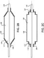
Figure 2B illustrates a cross-sectional view of a balloon catheter having a coned shoulder geometry in accordance with the present disclosure; -
Figure 2C illustrates a cross-sectional view of another balloon catheter having a stepped shoulder geometry in accordance with the present invention; and -
Figures 3A-3C illustrate an example of a balloon catheter in accordance with the present disclosure inflated to increasing pressures. - Persons skilled in the art will readily appreciate that various aspects of the present disclosure may be realized by any number of methods and apparatuses configured to perform the intended functions. Stated differently, other methods and apparatuses may be incorporated herein to perform the intended functions. It should also be noted that the accompanying drawing figures referred to herein are not all drawn to scale, but may be exaggerated to illustrate various aspects of the present disclosure, and in that regard, the drawing figures should not be construed as limiting.
- In general, the present disclosure is directed toward balloons and methods of making thereof that reduce stress being exerted directly onto balloon seals.
- With reference to
FIG. 1 , the present disclosure comprises aballoon 100. In general,balloon 100 comprises a collapsed configuration and an expanded configuration. In an expanded configuration,balloon 100 further comprises ashoulder portion 110 at each end ofballoon 100.Shoulder portion 110 is that region where the diameter ofballoon 100 circumferentially transitions between a larger diameter of a body portion or workinglength 120 ofballoon 100 and a smaller diameter of aseal portion 130 ofballoon 100. As shown inFigure 1 , these shoulder regions can assume a non-tapering, generally vertical, and/or square configuration upon inflation. - As illustrated,
seal portion 130 generally operates to secureballoon 100 about acatheter 140 and provide a fluid tight interface betweenballoon 100 andcatheter 140.Catheter 140 is typically provided with an inflation lumen and an outlet (not shown) for inflation of the balloon with an inflation media. In an embodiment,seal portion 130 comprises a reinforcement feature such as a plurality of wraps of a polymer film having a polymer and/or adhesive imbibed or deposited, on at least one surface of or at least partially into the film. For instance, the seal reinforcements can be formed using a plurality of wraps of an ePTFE film at least partially imbibed with cyanoacrylate imbibed. -
Balloon 100 can further comprise a balloon cover surrounding a substantial portion ofballoon 100. As used herein, reference made to a "balloon" shall be construed to also include a "balloon cover," as the geometries and structural configurations described below can be applied to a balloon cover in the same or a similar manner as a balloon. -
Balloon 100 can comprise materials which are compliant to semi-compliant or materials that can be used to construct balloons with limited distensibility, e.g., wrapped polymeric materials. For example,balloon 100 can comprise one or more fluoropolymers like expanded polytetrafluoroethylene ("ePTFE"), expanded modified PTFE, expanded copolymers of PTFE, expanded polyethylene, and the like. In various embodiments,balloon 100 can comprise a helically, circumferentially, axially oriented balloon wall, such as by wrapping an ePTFE film to formballoon 100. As used herein, the term "axial" is interchangeable with the term "longitudinal." As used herein, "circumferential" means an angle that is substantially perpendicular to the longitudinal axis. As used herein, "helical" means an angle that is not parallel to the longitudinal axis and not substantially perpendicular. In various embodiments, to form a helically oriented balloon material, a film can be helically wrapped into a tubular form. Orientation can refer to the direction of a particular property, such as a strength or a microstructure feature, e.g., the fibrils. - Other materials with similar properties are within the scope of the present disclosure. For example, balloon 100 can be fabricated from a variety of commonly known materials such as Amorphous Commodity Thermoplastics that include Polymethyl Methacrylate (PMMA or Acrylic), Polystyrene (PS), Acrylonitrile Butadiene Styrene (ABS), Polyvinyl Chloride (PVC), Modified Polyethylene Terephthalate Glycol (PETG), Cellulose Acetate Butyrate (CAB); Semi-Crystalline Commodity Plastics that include Polyethylene (PE), High Density Polyethylene (HDPE), Low Density Polyethylene (LDPE or LLDPE), Polypropylene (PP), Polymethylpentene (PMP); Amorphous Engineering Thermoplastics that include Polycarbonate (PC), Polyphenylene Oxide (PPO), Modified Polyphenylene Oxide (Mod PPO), Polyphenylene Ether (PPE), Modified Polyphenelyne Ether (Mod PPE), Thermoplastic Polyurethane (TPU); Semi-Crystalline Engineering Thermoplastics that include Polyamide (PA or Nylon), Polyoxymethylene (POM or Acetal), Polyethylene Terephthalate (PET, Thermoplastic Polyester), Polybutylene Terephthalate (PBT, Thermoplastic Polyester), Ultra High Molecular Weight Polyethylene (UHMW-PE); High Performance Thermoplastics that include Polyimide (PI, Imidized Plastic), Polyamide Imide (PAI, Imidized Plastic), Polybenzimidazole (PBI, Imidized Plastic); Amorphous High Performance Thermoplastics that include Polysulfone (PSU), Polyetherimide (PEI), Polyether Sulfone (PES), Polyaryl Sulfone (PAS); Semi-Crystalline High Performance Thermoplastics that include Polyphenylene Sulfide (PPS), Polyetheretherketone (PEEK); and Semi-Crystalline High Performance Thermoplastics, Fluoropolymers that include Fluorinated Ethylene Propylene (FEP), Ethylene Chlorotrifluroethylene (ECTFE), Ethylene, Ethylene Tetrafluoroethylene (ETFE), Polychlortrifluoroethylene (PCTFE), Polytetrafluoroethylene (PTFE), Polyvinylidene Fluoride (PVDF), Perfluoroalkoxy (PFA). Other commonly known medical grade materials include elastomeric organosilicon polymers, polyether block amide or thermoplastic copolyether (PEBAX). In addition, expandable balloons can be made from urethanes, silicones, fluoroelastomers, elastomers, and polyetherblockamides.
- In accordance with the present disclosure, with reference to
FIGS. 2A-2C ,shoulder portion 110 ofballoon 100 can comprise a load sharing geometry upon inflation. Further,shoulder portion 110 ofballoon 100 can comprise one or more load sharing members that facilitate a load sharing geometry upon inflation. - A load sharing geometry is generally any inflated geometry of
shoulder portion 110 ofballoon 100 that reduces stress being exerted directly onto balloon seals. Without intending to be bound by theory, it is believed that hoop and end stress is directly proportional to the balloon diameter adjacent to the seal and can thus be lowered by a stepwise decrease to seal diameter from full diameter. In this regard,balloon 100 comprises a longitudinal axis extending therethrough, wherein anouter edge 121 ofbody portion 120 andinner edge 131 ofseal portion 130 are longitudinally offset or spaced apart. More specifically, load sharing geometry comprises a stepped geometry. - As defined in the invention and with reference to
FIGS. 2A and2C , a stepped geometry can comprise one or morecircumferential steps 112 at an intermediate diameter between a larger diameter ofbody portion 120 ofballoon 100 and a smaller diameter ofseal portion 130 ofballoon 100. As illustrated,step 112 can comprise a circumferential ridge at a diameter less than the diameter of thebody portion 120. The ridge can oriented substantially parallel to the longitudinal axis. The steppedballoon shoulder 110 can comprise at least two sections forming an angle of about 90 degrees adjacent the ridge, yet other angles greater than or less than 90 degrees are within the scope of the present disclosure. - With reference to the example not forming part of the invention of 2B, a coned or tapered geometry can comprise a
circumferential taper 114 between a larger diameter ofbody portion 120 ofballoon 100 and a smaller diameter ofseal portion 130 ofballoon 100. As illustrated,taper 114 can form an angle between about 35 to 65 degrees angle, yet other angles greater than or less than the stated range are within the scope of the present disclosure. - Other geometries are possible and for illustration only for example, one that comprises a curve transition between the larger diameter of
body portion 120 ofballoon 100 and the smaller diameter ofseal portion 130 ofballoon 100. - In embodiments, a load sharing geometry is imparted to a shoulder of a balloon by one or more load sharing members. At least a portion of a load sharing member is less distensible than the body portion. Less distensible load sharing member can comprise a material of a higher durometer or stiffness than the material of the body portion, a material and/or construct that is less distensible than the material or construct of the body portion, a material or construct that is non-distensible, or any material or construct that inhibits distension of the shoulder portion beyond an intermediate diameter, i.e., a diameter between the larger diameter of the body portion of a balloon and the smaller diameter of the seal of the balloon. In various embodiments, a load sharing member is outside of the body portion or working length of the balloon, e.g., the portion which is intended to contact the luminal surface of an endoprosthetic device and/or surrounding tissue, and away from or extending only along the shoulder portion toward the seals of a balloon.
- In some embodiments, a load sharing member facilitates a load sharing geometry but does not extend along a substantial portion of
shoulder 110; e.g., the load sharing member is isolated to an intermediate portion of the shoulder. With reference back toFIG. 2A , a load sharing member can comprise aband 113 that facilitatescircumferential step 112 and imparts a stepped shoulder geometry. In other examples not forming part of the invention, a load sharing member substantially extends along a substantial portion ofshoulder 110. For example, and with reference toFIG. 2B , a load sharing member can comprise aconical frustum 115 that extends along a substantial portion ofshoulder 110 to form a coned or tapered shoulder geometry. Other geometries are within the scope of the present disclosure as well. - With reference to
FIG. 2C , in other embodiments,shoulder portion 110 can comprise multiple load sharing members, such as, for example more than oneband 113. - In some embodiments, a load sharing member is a region (e.g., a band) of a balloon where the balloon material is modified. One such modification comprises densifying the balloon material, for example ePTFE, along a target region of the shoulder. Such densification can be graded to create a load sharing geometry. In various embodiments, densifying can be accomplished by applying pressure and/or localized heat to a target region of the balloon material (e.g., by sintering, lasering, lasering in a pattern, etc.).
- Another such modification comprises coating or imbibing a target region of a balloon shoulder with a generally less distensible or non-distensible material (e.g., fluorinated ethylene propylene (FEP), PATT, a thermoplastic, nylon, and the like). For example, in illustrative embodiments comprising an ePTFE balloon material, imbibing involves at least partially filling the pores of the porous ePTFE with the generally less distensible polymeric material at the target region.
- In various embodiments, the shoulder portion can comprise or consist essentially of a second material having a durometer that is higher than that of the body portion of the balloon. In other words, the material of the body portion would not be continuous from the body portion along the shoulder portion to the seal but is interrupted by the second material in at least a portion of the shoulder portion.
- In various embodiments, a load sharing member can be a structural reinforcement (e.g., having a band) that has been added to a region of a balloon. Such a structural reinforcement can be situated between layers of a balloon, between a balloon and a balloon cover, on the surface of a balloon, and/or under the balloon wall. Such a structural reinforcement can be adhered (such as through use of a heat treatment and/or adhesive) to the balloon/balloon cover or otherwise fixed in position. In accordance with an aspect of such embodiments, a structural reinforcement can comprise a wrapped member, a molded member, a woven or knitted member, a die cut or laser cut member, or any other appropriately shaped reinforcement construct.
- For example, a structural reinforcement can comprise a material that has been wrapped on an appropriately shaped mandrel and densified or imbibed as described above.
- For example, a structural reinforcement can comprise a polymeric material of higher durometer than the body portion that is molded (e.g., blown or extruded) into an appropriate shape.
- For example, a structural reinforcement comprises a pattern cut reinforcement or similar structure. The pattern cut reinforcement can comprise nitinol or other similar shape memory material. For example, a nitinol reinforcement can comprise a collapsible annular member like a stent ring to facilitate a stepped geometry.
- Thus, in accordance with the present disclosure, a load sharing geometry reduces stress being exerted directly onto balloon seals and thereby reduces failure rates associated with balloon catheters.
- Example of making an ePTFE wrapped balloon cover comprising a stepped load sharing geometry:
A stepped balloon can be manufactured as follows. An ePTFE balloon cover (e.g., a cover comprising a wrapped ePTFE film) can be mounted on a mandrel at a first diameter (e.g., 8 millimeters) and necked or reduced in diameter to a necked portion having a necked diameter of approximately (0.070 inches) 1.778 millimeters. The cover can then be expanded to approximately 4 millimeters and placed over a similarly sized mandrel. An anisotropic ePTFE film strip (approximately 5mm wide) coated with a thermoplastic copolymer of tetrafluoroethylene and perfluoroalkylvinylether (as described inU.S. Patent No. 7,462,675 to Chang et al. ) can then be wrapped around the cover about the sections of the cover to be part of the shoulder portion. The film can be wrapped at least two times so that the stronger direction of the film strip will oriented around the circumference of the balloon. The ePTFE film strip can be a dense, strong ePTFE that is 2-6 µm thick made generally in accordance with the teachings ofU.S. Patent 7,521,010 to Kennedy . The thickness of the copolymer coating can range from 1-3µm. The section of the cover having the 5mm ePTFE film strip wrapping can be thermally treated after wrapping to cause the layers to adhere to each other and to the cover. The cover can then be placed over a balloon and secured to the catheter at each end. - The covered balloon can be inserted into a tube of material configured to shrink or contract at a particular temperature (e.g., an FEP shrink tube), and the covered balloon, once in position, can be heated at approximately 260 degrees Celsius. The covered balloon can be further reduced in diameter, or sized down from a 4 mm intermediate diameter, to approximately (0.100 inches) 2.5 millimeters using a radial crusher.
- Thus, as described, a balloon can be manufactured to a stepped, load sharing geometry.
FIGS. 3A-3C show such a coveredballoon 300 inflated to increasing pressures, from 1.42-2.43 MPa (14 to 24 atmospheres). As can be seen, at lower pressures, the difference between the diameter of the balloon atbody portion 120 and the diameter atcircumferential step 312 is less than at greater pressures, butcircumferential step 312 is non-distensible beyond an intermediate diameter even as the body ofballoon 300 increases in diameter under increasing pressures. - It will be apparent to those skilled in the art that various modifications and variations can be made in the present disclosure without departing from the scope of the disclosure as defined by the appended claims. Thus, it is intended that the embodiments described herein cover the modifications and variations of this disclosure provided they come within the scope of the appended claims and their equivalents.
- Numerous characteristics and advantages have been set forth in the preceding description, including various alternatives together with details of the structure and function of the devices and/or methods. The disclosure is intended as illustrative only and as such is not intended to be exhaustive. It will be evident to those skilled in the art that various modifications can be made, especially in matters of structure, materials, elements, components, shape, size and arrangement of parts including combinations within the principles of the invention, to the full extent indicated by the broad, general meaning of the terms in which the appended claims are expressed. To the extent that these various modifications do not depart from the scope of the appended claims, they are intended to be encompassed therein.
Claims (15)
- A balloon (100) comprising:a body portion (120) inflatable to a first diameter;two seal portions (130), each having a second diameter smaller than the first diameter; andtwo shoulder portions (110), each defining a transition between the first diameter and the second diameter between an outer edge (121) of the body portion and a longitudinally offset inner edge (131) of one of the two seal portions,wherein at least one shoulder portion comprises a load sharing member (113) and a stepped geometry comprising a generally square configuration upon inflation of the balloon.
- The balloon (100) of claim 1, wherein the load sharing member comprises a structural reinforcement.
- The balloon (100) of claim 1, wherein the body portion comprises a wrapped polymeric material.
- The balloon (100) of claim 1, wherein the load sharing member comprises a material that is a higher durometer than the body portion, or the load sharing member is isolated to an intermediate section of a shoulder portion, or the load sharing member comprises at least one of densified ePTFE or imbibed ePTFE.
- The balloon (100) of claim 1, wherein the load sharing member is located outside of the body portion of the balloon.
- The balloon (100) of claim 1, wherein the load sharing member comprises a nitinol reinforcement.
- The balloon (100) of claim 1, wherein the stepped geometry comprises one or more circumferential steps (112).
- The balloon (100) of claim 1, wherein the load sharing member comprises a band (113) to facilitate a circumferential step (112).
- The balloon (100) of claim 1, wherein the body portion (120) comprisies a wrapped polymeric material and the load sharing member is adapted to inhibit inflation beyond a diameter between the first diameter and the second diameter along at least a section of a shoulder portion.
- The balloon (100) of claim 9, wherein the wrapped polymeric material comprises an expanded fluoropolymer.
- The balloon (100) of claim 9, wherein the load sharing member comprises a structural reinforcement.
- The balloon (100) of claim 9, wherein the load sharing member is isolated to an intermediate section of the shoulder portion.
- The balloon (100) of claim 9, wherein the load sharing member comprises a material that is a higher durometer than the wrapped polymeric material of the body portion; or the load sharing member comprises at least one of densified ePTFE or imbibed ePTFE.
- The balloon (100) of claim 9, wherein the load sharing member is located outside of the body portion of the balloon; or wherein load sharing member comprises a nitinol reinforcement.
- A method for reducing the hoop stress applied to a seal portion (130) of an expandable balloon (100) having a body portion (120) inflatable to a first diameter, two seal portions, each having a second diameter smaller than the first diameter; and two shoulder portions (110), each defining a transition between the first diameter and the second diameter between an outer edge (121) of the body portion and a longitudinally offset inner edge (131) of one of the two seal portions, the method comprising the step of:
placing a load sharing member around a balloon along at least a portion of at least one of the two shoulder portions, wherein the balloon comprises a wrapped polymeric material, to provide a stepped geometry comprising a generally square configuration upon inflation of the balloon.
Applications Claiming Priority (3)
| Application Number | Priority Date | Filing Date | Title |
|---|---|---|---|
| US201361799638P | 2013-03-15 | 2013-03-15 | |
| US14/185,223 US11116947B2 (en) | 2013-03-15 | 2014-02-20 | Balloon seal stress reduction and related systems and methods |
| PCT/US2014/017653 WO2014149359A1 (en) | 2013-03-15 | 2014-02-21 | Balloon seal stress reduction and related systems and method of production |
Publications (2)
| Publication Number | Publication Date |
|---|---|
| EP2968859A1 EP2968859A1 (en) | 2016-01-20 |
| EP2968859B1 true EP2968859B1 (en) | 2021-10-13 |
Family
ID=51531077
Family Applications (1)
| Application Number | Title | Priority Date | Filing Date |
|---|---|---|---|
| EP14710119.0A Active EP2968859B1 (en) | 2013-03-15 | 2014-02-21 | Balloon with seal stress reduction and method of production |
Country Status (11)
| Country | Link |
|---|---|
| US (1) | US11116947B2 (en) |
| EP (1) | EP2968859B1 (en) |
| JP (4) | JP6777538B2 (en) |
| KR (1) | KR20150126922A (en) |
| CN (2) | CN105050649A (en) |
| AU (1) | AU2014238269B2 (en) |
| BR (1) | BR112015020288A2 (en) |
| CA (1) | CA2901217C (en) |
| ES (1) | ES2900313T3 (en) |
| HK (1) | HK1216018A1 (en) |
| WO (1) | WO2014149359A1 (en) |
Families Citing this family (2)
| Publication number | Priority date | Publication date | Assignee | Title |
|---|---|---|---|---|
| US10433857B2 (en) * | 2016-06-24 | 2019-10-08 | Bryan Medical, Inc. | Balloon dilation catheter |
| CN115920212B (en) * | 2022-12-02 | 2025-10-10 | 科睿驰(深圳)医疗科技发展有限公司 | Balloon microcatheter and balloon microcatheter preparation method |
Citations (1)
| Publication number | Priority date | Publication date | Assignee | Title |
|---|---|---|---|---|
| US6120523A (en) * | 1994-02-24 | 2000-09-19 | Radiance Medical Systems, Inc. | Focalized intraluminal balloons |
Family Cites Families (32)
| Publication number | Priority date | Publication date | Assignee | Title |
|---|---|---|---|---|
| US5358486A (en) | 1987-01-09 | 1994-10-25 | C. R. Bard, Inc. | Multiple layer high strength balloon for dilatation catheter |
| US4994072A (en) * | 1988-08-31 | 1991-02-19 | Meadox Medicals, Inc. | Dilation catheter |
| US5192296A (en) | 1988-08-31 | 1993-03-09 | Meadox Medicals, Inc. | Dilatation catheter |
| US5843116A (en) | 1996-05-02 | 1998-12-01 | Cardiovascular Dynamics, Inc. | Focalized intraluminal balloons |
| US5645560A (en) | 1995-12-15 | 1997-07-08 | Cardiovascular Dynamics, Inc. | Fixed focal balloon for interactive angioplasty and stent implantation |
| US5470313A (en) * | 1994-02-24 | 1995-11-28 | Cardiovascular Dynamics, Inc. | Variable diameter balloon dilatation catheter |
| US5522882A (en) | 1994-10-21 | 1996-06-04 | Impra, Inc. | Method and apparatus for balloon expandable stent-graft delivery |
| US20060271091A1 (en) | 1995-09-18 | 2006-11-30 | Campbell Carey V | Balloon catheter device |
| US5868704A (en) * | 1995-09-18 | 1999-02-09 | W. L. Gore & Associates, Inc. | Balloon catheter device |
| CA2244639A1 (en) | 1997-08-11 | 1999-02-11 | Advanced Cardiovascular Systems, Inc. | Retainer for a stent-carrying balloon catheter |
| CA2307021A1 (en) | 1997-10-08 | 1999-04-15 | Kaneka Corporation | Balloon catheter and method for manufacturing same |
| US6210408B1 (en) | 1999-02-24 | 2001-04-03 | Scimed Life Systems, Inc. | Guide wire system for RF recanalization of vascular blockages |
| CN1473058A (en) | 2001-08-08 | 2004-02-04 | ��Ԩ��ѧ��ҵ��ʽ���� | Dilation Catheter |
| JP4955162B2 (en) | 2001-08-28 | 2012-06-20 | テルモ株式会社 | Balloon for living organ dilator and living organ dilator |
| US6737158B1 (en) | 2002-10-30 | 2004-05-18 | Gore Enterprise Holdings, Inc. | Porous polymeric membrane toughened composites |
| EP1557193B1 (en) | 2004-01-22 | 2008-03-05 | Nipro Corporation | Balloon catheter |
| JP4586545B2 (en) | 2004-01-22 | 2010-11-24 | ニプロ株式会社 | Balloon catheter |
| US7879053B2 (en) * | 2004-12-20 | 2011-02-01 | Boston Scientific Scimed, Inc. | Balloon with stepped sections and implements |
| US20080125711A1 (en) * | 2006-08-07 | 2008-05-29 | Alpini Alfred A | Catheter balloons with integrated non-distensible seals |
| US20080140173A1 (en) | 2006-08-07 | 2008-06-12 | Sherif Eskaros | Non-shortening wrapped balloon |
| US9180279B2 (en) * | 2006-08-07 | 2015-11-10 | W. L. Gore & Associates, Inc. | Inflatable imbibed polymer devices |
| US7785290B2 (en) * | 2006-08-07 | 2010-08-31 | Gore Enterprise Holdings, Inc. | Non-shortening high angle wrapped balloons |
| DE102008040914A1 (en) | 2008-08-01 | 2010-02-04 | Biotronik Vi Patent Ag | Balloon catheter and process for its preparation |
| WO2010079494A1 (en) | 2009-01-12 | 2010-07-15 | Angioslide Ltd. | Balloon and catheter system and methods for making and use thereof |
| US20120109057A1 (en) | 2009-02-18 | 2012-05-03 | Hotspur Technologies, Inc. | Apparatus and methods for treating obstructions within body lumens |
| CN101822867A (en) | 2009-03-02 | 2010-09-08 | 东莞市迪凯精密管材有限公司 | PEEK balloon dilatation catheter |
| JP2011206124A (en) | 2010-03-29 | 2011-10-20 | Terumo Corp | Balloon catheter |
| US9028444B2 (en) * | 2011-04-15 | 2015-05-12 | W. L. Gore & Associates, Inc. | Pivoting ring seal |
| US9370643B2 (en) * | 2011-06-23 | 2016-06-21 | W.L. Gore & Associates, Inc. | High strength balloon cover |
| US10016579B2 (en) * | 2011-06-23 | 2018-07-10 | W.L. Gore & Associates, Inc. | Controllable inflation profile balloon cover apparatus |
| US9370647B2 (en) | 2011-07-14 | 2016-06-21 | W. L. Gore & Associates, Inc. | Expandable medical devices |
| US9402983B1 (en) * | 2012-10-31 | 2016-08-02 | Sainath Intellectual Properties, Llc | Variably expanding balloon catheter |
-
2014
- 2014-02-20 US US14/185,223 patent/US11116947B2/en active Active
- 2014-02-21 CA CA2901217A patent/CA2901217C/en active Active
- 2014-02-21 BR BR112015020288A patent/BR112015020288A2/en not_active Application Discontinuation
- 2014-02-21 KR KR1020157027845A patent/KR20150126922A/en not_active Ceased
- 2014-02-21 AU AU2014238269A patent/AU2014238269B2/en active Active
- 2014-02-21 JP JP2016500331A patent/JP6777538B2/en active Active
- 2014-02-21 CN CN201480014764.4A patent/CN105050649A/en active Pending
- 2014-02-21 EP EP14710119.0A patent/EP2968859B1/en active Active
- 2014-02-21 CN CN201910870684.3A patent/CN110478603A/en active Pending
- 2014-02-21 ES ES14710119T patent/ES2900313T3/en active Active
- 2014-02-21 HK HK16103929.2A patent/HK1216018A1/en unknown
- 2014-02-21 WO PCT/US2014/017653 patent/WO2014149359A1/en not_active Ceased
-
2019
- 2019-01-25 JP JP2019011570A patent/JP7193360B2/en active Active
-
2021
- 2021-04-01 JP JP2021062996A patent/JP7359800B2/en active Active
-
2023
- 2023-07-28 JP JP2023123532A patent/JP7721600B2/en active Active
Patent Citations (1)
| Publication number | Priority date | Publication date | Assignee | Title |
|---|---|---|---|---|
| US6120523A (en) * | 1994-02-24 | 2000-09-19 | Radiance Medical Systems, Inc. | Focalized intraluminal balloons |
Also Published As
| Publication number | Publication date |
|---|---|
| AU2014238269B2 (en) | 2017-04-06 |
| JP2023153908A (en) | 2023-10-18 |
| JP6777538B2 (en) | 2020-10-28 |
| JP2019093168A (en) | 2019-06-20 |
| JP7193360B2 (en) | 2022-12-20 |
| JP7721600B2 (en) | 2025-08-12 |
| CA2901217C (en) | 2018-07-24 |
| AU2014238269A1 (en) | 2015-09-10 |
| KR20150126922A (en) | 2015-11-13 |
| BR112015020288A2 (en) | 2017-07-18 |
| CN110478603A (en) | 2019-11-22 |
| JP2021112578A (en) | 2021-08-05 |
| JP2016514015A (en) | 2016-05-19 |
| CN105050649A (en) | 2015-11-11 |
| US11116947B2 (en) | 2021-09-14 |
| US20140277065A1 (en) | 2014-09-18 |
| JP7359800B2 (en) | 2023-10-11 |
| WO2014149359A1 (en) | 2014-09-25 |
| ES2900313T3 (en) | 2022-03-16 |
| EP2968859A1 (en) | 2016-01-20 |
| HK1216018A1 (en) | 2016-10-07 |
| CA2901217A1 (en) | 2014-09-25 |
Similar Documents
| Publication | Publication Date | Title |
|---|---|---|
| CN106334251B (en) | High strength airbag cover and method of manufacture | |
| US10016579B2 (en) | Controllable inflation profile balloon cover apparatus | |
| US8597240B2 (en) | Coaxial catheter shaft having balloon attachment feature with axial fluid path | |
| JP2022017388A (en) | Medical balloon device and method | |
| EP4091642A1 (en) | Medical balloon | |
| JP7721600B2 (en) | Balloon seal stress relief and related systems and methods of manufacture | |
| US9968768B2 (en) | Medical tube, balloon catheter and method of manufacturing medical tube | |
| CN107206217B (en) | Balloon catheter |
Legal Events
| Date | Code | Title | Description |
|---|---|---|---|
| PUAI | Public reference made under article 153(3) epc to a published international application that has entered the european phase |
Free format text: ORIGINAL CODE: 0009012 |
|
| 17P | Request for examination filed |
Effective date: 20150917 |
|
| AK | Designated contracting states |
Kind code of ref document: A1 Designated state(s): AL AT BE BG CH CY CZ DE DK EE ES FI FR GB GR HR HU IE IS IT LI LT LU LV MC MK MT NL NO PL PT RO RS SE SI SK SM TR |
|
| AX | Request for extension of the european patent |
Extension state: BA ME |
|
| DAX | Request for extension of the european patent (deleted) | ||
| REG | Reference to a national code |
Ref country code: HK Ref legal event code: DE Ref document number: 1216018 Country of ref document: HK |
|
| STAA | Information on the status of an ep patent application or granted ep patent |
Free format text: STATUS: EXAMINATION IS IN PROGRESS |
|
| 17Q | First examination report despatched |
Effective date: 20200624 |
|
| GRAP | Despatch of communication of intention to grant a patent |
Free format text: ORIGINAL CODE: EPIDOSNIGR1 |
|
| STAA | Information on the status of an ep patent application or granted ep patent |
Free format text: STATUS: GRANT OF PATENT IS INTENDED |
|
| INTG | Intention to grant announced |
Effective date: 20210527 |
|
| GRAS | Grant fee paid |
Free format text: ORIGINAL CODE: EPIDOSNIGR3 |
|
| GRAA | (expected) grant |
Free format text: ORIGINAL CODE: 0009210 |
|
| STAA | Information on the status of an ep patent application or granted ep patent |
Free format text: STATUS: THE PATENT HAS BEEN GRANTED |
|
| AK | Designated contracting states |
Kind code of ref document: B1 Designated state(s): AL AT BE BG CH CY CZ DE DK EE ES FI FR GB GR HR HU IE IS IT LI LT LU LV MC MK MT NL NO PL PT RO RS SE SI SK SM TR |
|
| REG | Reference to a national code |
Ref country code: GB Ref legal event code: FG4D |
|
| REG | Reference to a national code |
Ref country code: CH Ref legal event code: EP |
|
| REG | Reference to a national code |
Ref country code: DE Ref legal event code: R096 Ref document number: 602014080630 Country of ref document: DE |
|
| REG | Reference to a national code |
Ref country code: IE Ref legal event code: FG4D |
|
| REG | Reference to a national code |
Ref country code: AT Ref legal event code: REF Ref document number: 1437710 Country of ref document: AT Kind code of ref document: T Effective date: 20211115 |
|
| REG | Reference to a national code |
Ref country code: NL Ref legal event code: FP |
|
| REG | Reference to a national code |
Ref country code: LT Ref legal event code: MG9D |
|
| REG | Reference to a national code |
Ref country code: AT Ref legal event code: MK05 Ref document number: 1437710 Country of ref document: AT Kind code of ref document: T Effective date: 20211013 |
|
| REG | Reference to a national code |
Ref country code: ES Ref legal event code: FG2A Ref document number: 2900313 Country of ref document: ES Kind code of ref document: T3 Effective date: 20220316 |
|
| PG25 | Lapsed in a contracting state [announced via postgrant information from national office to epo] |
Ref country code: RS Free format text: LAPSE BECAUSE OF FAILURE TO SUBMIT A TRANSLATION OF THE DESCRIPTION OR TO PAY THE FEE WITHIN THE PRESCRIBED TIME-LIMIT Effective date: 20211013 Ref country code: LT Free format text: LAPSE BECAUSE OF FAILURE TO SUBMIT A TRANSLATION OF THE DESCRIPTION OR TO PAY THE FEE WITHIN THE PRESCRIBED TIME-LIMIT Effective date: 20211013 Ref country code: FI Free format text: LAPSE BECAUSE OF FAILURE TO SUBMIT A TRANSLATION OF THE DESCRIPTION OR TO PAY THE FEE WITHIN THE PRESCRIBED TIME-LIMIT Effective date: 20211013 Ref country code: BG Free format text: LAPSE BECAUSE OF FAILURE TO SUBMIT A TRANSLATION OF THE DESCRIPTION OR TO PAY THE FEE WITHIN THE PRESCRIBED TIME-LIMIT Effective date: 20220113 Ref country code: AT Free format text: LAPSE BECAUSE OF FAILURE TO SUBMIT A TRANSLATION OF THE DESCRIPTION OR TO PAY THE FEE WITHIN THE PRESCRIBED TIME-LIMIT Effective date: 20211013 |
|
| PG25 | Lapsed in a contracting state [announced via postgrant information from national office to epo] |
Ref country code: IS Free format text: LAPSE BECAUSE OF FAILURE TO SUBMIT A TRANSLATION OF THE DESCRIPTION OR TO PAY THE FEE WITHIN THE PRESCRIBED TIME-LIMIT Effective date: 20220213 Ref country code: SE Free format text: LAPSE BECAUSE OF FAILURE TO SUBMIT A TRANSLATION OF THE DESCRIPTION OR TO PAY THE FEE WITHIN THE PRESCRIBED TIME-LIMIT Effective date: 20211013 Ref country code: PT Free format text: LAPSE BECAUSE OF FAILURE TO SUBMIT A TRANSLATION OF THE DESCRIPTION OR TO PAY THE FEE WITHIN THE PRESCRIBED TIME-LIMIT Effective date: 20220214 Ref country code: PL Free format text: LAPSE BECAUSE OF FAILURE TO SUBMIT A TRANSLATION OF THE DESCRIPTION OR TO PAY THE FEE WITHIN THE PRESCRIBED TIME-LIMIT Effective date: 20211013 Ref country code: NO Free format text: LAPSE BECAUSE OF FAILURE TO SUBMIT A TRANSLATION OF THE DESCRIPTION OR TO PAY THE FEE WITHIN THE PRESCRIBED TIME-LIMIT Effective date: 20220113 Ref country code: LV Free format text: LAPSE BECAUSE OF FAILURE TO SUBMIT A TRANSLATION OF THE DESCRIPTION OR TO PAY THE FEE WITHIN THE PRESCRIBED TIME-LIMIT Effective date: 20211013 Ref country code: HR Free format text: LAPSE BECAUSE OF FAILURE TO SUBMIT A TRANSLATION OF THE DESCRIPTION OR TO PAY THE FEE WITHIN THE PRESCRIBED TIME-LIMIT Effective date: 20211013 Ref country code: GR Free format text: LAPSE BECAUSE OF FAILURE TO SUBMIT A TRANSLATION OF THE DESCRIPTION OR TO PAY THE FEE WITHIN THE PRESCRIBED TIME-LIMIT Effective date: 20220114 |
|
| REG | Reference to a national code |
Ref country code: DE Ref legal event code: R097 Ref document number: 602014080630 Country of ref document: DE |
|
| PG25 | Lapsed in a contracting state [announced via postgrant information from national office to epo] |
Ref country code: SM Free format text: LAPSE BECAUSE OF FAILURE TO SUBMIT A TRANSLATION OF THE DESCRIPTION OR TO PAY THE FEE WITHIN THE PRESCRIBED TIME-LIMIT Effective date: 20211013 Ref country code: SK Free format text: LAPSE BECAUSE OF FAILURE TO SUBMIT A TRANSLATION OF THE DESCRIPTION OR TO PAY THE FEE WITHIN THE PRESCRIBED TIME-LIMIT Effective date: 20211013 Ref country code: RO Free format text: LAPSE BECAUSE OF FAILURE TO SUBMIT A TRANSLATION OF THE DESCRIPTION OR TO PAY THE FEE WITHIN THE PRESCRIBED TIME-LIMIT Effective date: 20211013 Ref country code: EE Free format text: LAPSE BECAUSE OF FAILURE TO SUBMIT A TRANSLATION OF THE DESCRIPTION OR TO PAY THE FEE WITHIN THE PRESCRIBED TIME-LIMIT Effective date: 20211013 Ref country code: DK Free format text: LAPSE BECAUSE OF FAILURE TO SUBMIT A TRANSLATION OF THE DESCRIPTION OR TO PAY THE FEE WITHIN THE PRESCRIBED TIME-LIMIT Effective date: 20211013 Ref country code: CZ Free format text: LAPSE BECAUSE OF FAILURE TO SUBMIT A TRANSLATION OF THE DESCRIPTION OR TO PAY THE FEE WITHIN THE PRESCRIBED TIME-LIMIT Effective date: 20211013 |
|
| PLBE | No opposition filed within time limit |
Free format text: ORIGINAL CODE: 0009261 |
|
| STAA | Information on the status of an ep patent application or granted ep patent |
Free format text: STATUS: NO OPPOSITION FILED WITHIN TIME LIMIT |
|
| REG | Reference to a national code |
Ref country code: HK Ref legal event code: WD Ref document number: 1216018 Country of ref document: HK |
|
| 26N | No opposition filed |
Effective date: 20220714 |
|
| PG25 | Lapsed in a contracting state [announced via postgrant information from national office to epo] |
Ref country code: MC Free format text: LAPSE BECAUSE OF FAILURE TO SUBMIT A TRANSLATION OF THE DESCRIPTION OR TO PAY THE FEE WITHIN THE PRESCRIBED TIME-LIMIT Effective date: 20211013 |
|
| REG | Reference to a national code |
Ref country code: CH Ref legal event code: PL |
|
| REG | Reference to a national code |
Ref country code: BE Ref legal event code: MM Effective date: 20220228 |
|
| PG25 | Lapsed in a contracting state [announced via postgrant information from national office to epo] |
Ref country code: LU Free format text: LAPSE BECAUSE OF NON-PAYMENT OF DUE FEES Effective date: 20220221 Ref country code: AL Free format text: LAPSE BECAUSE OF FAILURE TO SUBMIT A TRANSLATION OF THE DESCRIPTION OR TO PAY THE FEE WITHIN THE PRESCRIBED TIME-LIMIT Effective date: 20211013 |
|
| PG25 | Lapsed in a contracting state [announced via postgrant information from national office to epo] |
Ref country code: SI Free format text: LAPSE BECAUSE OF FAILURE TO SUBMIT A TRANSLATION OF THE DESCRIPTION OR TO PAY THE FEE WITHIN THE PRESCRIBED TIME-LIMIT Effective date: 20211013 |
|
| PG25 | Lapsed in a contracting state [announced via postgrant information from national office to epo] |
Ref country code: LI Free format text: LAPSE BECAUSE OF NON-PAYMENT OF DUE FEES Effective date: 20220228 Ref country code: CH Free format text: LAPSE BECAUSE OF NON-PAYMENT OF DUE FEES Effective date: 20220228 |
|
| PG25 | Lapsed in a contracting state [announced via postgrant information from national office to epo] |
Ref country code: BE Free format text: LAPSE BECAUSE OF NON-PAYMENT OF DUE FEES Effective date: 20220228 |
|
| PG25 | Lapsed in a contracting state [announced via postgrant information from national office to epo] |
Ref country code: HU Free format text: LAPSE BECAUSE OF FAILURE TO SUBMIT A TRANSLATION OF THE DESCRIPTION OR TO PAY THE FEE WITHIN THE PRESCRIBED TIME-LIMIT; INVALID AB INITIO Effective date: 20140221 |
|
| PG25 | Lapsed in a contracting state [announced via postgrant information from national office to epo] |
Ref country code: MK Free format text: LAPSE BECAUSE OF FAILURE TO SUBMIT A TRANSLATION OF THE DESCRIPTION OR TO PAY THE FEE WITHIN THE PRESCRIBED TIME-LIMIT Effective date: 20211013 Ref country code: CY Free format text: LAPSE BECAUSE OF FAILURE TO SUBMIT A TRANSLATION OF THE DESCRIPTION OR TO PAY THE FEE WITHIN THE PRESCRIBED TIME-LIMIT Effective date: 20211013 |
|
| PG25 | Lapsed in a contracting state [announced via postgrant information from national office to epo] |
Ref country code: MT Free format text: LAPSE BECAUSE OF FAILURE TO SUBMIT A TRANSLATION OF THE DESCRIPTION OR TO PAY THE FEE WITHIN THE PRESCRIBED TIME-LIMIT Effective date: 20211013 |
|
| PG25 | Lapsed in a contracting state [announced via postgrant information from national office to epo] |
Ref country code: TR Free format text: LAPSE BECAUSE OF FAILURE TO SUBMIT A TRANSLATION OF THE DESCRIPTION OR TO PAY THE FEE WITHIN THE PRESCRIBED TIME-LIMIT Effective date: 20211013 |
|
| PGFP | Annual fee paid to national office [announced via postgrant information from national office to epo] |
Ref country code: NL Payment date: 20260121 Year of fee payment: 13 |
|
| PGFP | Annual fee paid to national office [announced via postgrant information from national office to epo] |
Ref country code: GB Payment date: 20260121 Year of fee payment: 13 |
|
| PGFP | Annual fee paid to national office [announced via postgrant information from national office to epo] |
Ref country code: ES Payment date: 20260302 Year of fee payment: 13 |
|
| PGFP | Annual fee paid to national office [announced via postgrant information from national office to epo] |
Ref country code: IE Payment date: 20260123 Year of fee payment: 13 Ref country code: DE Payment date: 20260121 Year of fee payment: 13 |
|
| PGFP | Annual fee paid to national office [announced via postgrant information from national office to epo] |
Ref country code: IT Payment date: 20260121 Year of fee payment: 13 |
|
| PGFP | Annual fee paid to national office [announced via postgrant information from national office to epo] |
Ref country code: FR Payment date: 20260121 Year of fee payment: 13 |