EP2968072B1 - Child resistant cover for oral dosage forms - Google Patents
Child resistant cover for oral dosage forms Download PDFInfo
- Publication number
- EP2968072B1 EP2968072B1 EP14716160.8A EP14716160A EP2968072B1 EP 2968072 B1 EP2968072 B1 EP 2968072B1 EP 14716160 A EP14716160 A EP 14716160A EP 2968072 B1 EP2968072 B1 EP 2968072B1
- Authority
- EP
- European Patent Office
- Prior art keywords
- cover
- safety device
- handle
- child resistant
- tab
- Prior art date
- Legal status (The legal status is an assumption and is not a legal conclusion. Google has not performed a legal analysis and makes no representation as to the accuracy of the status listed.)
- Active
Links
- 239000006186 oral dosage form Substances 0.000 title claims description 32
- 238000013016 damping Methods 0.000 claims description 9
- 230000007246 mechanism Effects 0.000 claims description 9
- 239000003795 chemical substances by application Substances 0.000 description 30
- 230000000994 depressogenic effect Effects 0.000 description 9
- 239000006187 pill Substances 0.000 description 8
- -1 sleep aids Substances 0.000 description 7
- 239000003814 drug Substances 0.000 description 6
- 229940079593 drug Drugs 0.000 description 5
- 239000000825 pharmaceutical preparation Substances 0.000 description 5
- 239000000730 antalgic agent Substances 0.000 description 4
- 230000000881 depressing effect Effects 0.000 description 4
- 229940126534 drug product Drugs 0.000 description 4
- 238000004806 packaging method and process Methods 0.000 description 4
- 229940035676 analgesics Drugs 0.000 description 3
- 239000002775 capsule Substances 0.000 description 3
- KWTSXDURSIMDCE-QMMMGPOBSA-N (S)-amphetamine Chemical compound C[C@H](N)CC1=CC=CC=C1 KWTSXDURSIMDCE-QMMMGPOBSA-N 0.000 description 2
- BRUQQQPBMZOVGD-XFKAJCMBSA-N Oxycodone Chemical compound O=C([C@@H]1O2)CC[C@@]3(O)[C@H]4CC5=CC=C(OC)C2=C5[C@@]13CCN4C BRUQQQPBMZOVGD-XFKAJCMBSA-N 0.000 description 2
- VIROVYVQCGLCII-UHFFFAOYSA-N amobarbital Chemical compound CC(C)CCC1(CC)C(=O)NC(=O)NC1=O VIROVYVQCGLCII-UHFFFAOYSA-N 0.000 description 2
- 230000001088 anti-asthma Effects 0.000 description 2
- 230000002686 anti-diuretic effect Effects 0.000 description 2
- 230000002921 anti-spasmodic effect Effects 0.000 description 2
- 239000000924 antiasthmatic agent Substances 0.000 description 2
- 239000000935 antidepressant agent Substances 0.000 description 2
- 229940005513 antidepressants Drugs 0.000 description 2
- 229940124538 antidiuretic agent Drugs 0.000 description 2
- 229940124575 antispasmodic agent Drugs 0.000 description 2
- ZRIHAIZYIMGOAB-UHFFFAOYSA-N butabarbital Chemical compound CCC(C)C1(CC)C(=O)NC(=O)NC1=O ZRIHAIZYIMGOAB-UHFFFAOYSA-N 0.000 description 2
- OROGSEYTTFOCAN-DNJOTXNNSA-N codeine Chemical compound C([C@H]1[C@H](N(CC[C@@]112)C)C3)=C[C@H](O)[C@@H]1OC1=C2C3=CC=C1OC OROGSEYTTFOCAN-DNJOTXNNSA-N 0.000 description 2
- 229960002428 fentanyl Drugs 0.000 description 2
- PJMPHNIQZUBGLI-UHFFFAOYSA-N fentanyl Chemical compound C=1C=CC=CC=1N(C(=O)CC)C(CC1)CCN1CCC1=CC=CC=C1 PJMPHNIQZUBGLI-UHFFFAOYSA-N 0.000 description 2
- 239000012530 fluid Substances 0.000 description 2
- OROGSEYTTFOCAN-UHFFFAOYSA-N hydrocodone Natural products C1C(N(CCC234)C)C2C=CC(O)C3OC2=C4C1=CC=C2OC OROGSEYTTFOCAN-UHFFFAOYSA-N 0.000 description 2
- WVLOADHCBXTIJK-YNHQPCIGSA-N hydromorphone Chemical compound O([C@H]1C(CC[C@H]23)=O)C4=C5[C@@]12CCN(C)[C@@H]3CC5=CC=C4O WVLOADHCBXTIJK-YNHQPCIGSA-N 0.000 description 2
- 229960001410 hydromorphone Drugs 0.000 description 2
- 239000003326 hypnotic agent Substances 0.000 description 2
- 230000000147 hypnotic effect Effects 0.000 description 2
- 239000004615 ingredient Substances 0.000 description 2
- 239000007788 liquid Substances 0.000 description 2
- 239000000463 material Substances 0.000 description 2
- BQJCRHHNABKAKU-KBQPJGBKSA-N morphine Chemical compound O([C@H]1[C@H](C=C[C@H]23)O)C4=C5[C@@]12CCN(C)[C@@H]3CC5=CC=C4O BQJCRHHNABKAKU-KBQPJGBKSA-N 0.000 description 2
- 230000003533 narcotic effect Effects 0.000 description 2
- 229940126701 oral medication Drugs 0.000 description 2
- 229960002085 oxycodone Drugs 0.000 description 2
- 239000000932 sedative agent Substances 0.000 description 2
- 239000000021 stimulant Substances 0.000 description 2
- 239000003826 tablet Substances 0.000 description 2
- DIWRORZWFLOCLC-HNNXBMFYSA-N (3s)-7-chloro-5-(2-chlorophenyl)-3-hydroxy-1,3-dihydro-1,4-benzodiazepin-2-one Chemical compound N([C@H](C(NC1=CC=C(Cl)C=C11)=O)O)=C1C1=CC=CC=C1Cl DIWRORZWFLOCLC-HNNXBMFYSA-N 0.000 description 1
- TVYLLZQTGLZFBW-ZBFHGGJFSA-N (R,R)-tramadol Chemical compound COC1=CC=CC([C@]2(O)[C@H](CCCC2)CN(C)C)=C1 TVYLLZQTGLZFBW-ZBFHGGJFSA-N 0.000 description 1
- YFGHCGITMMYXAQ-UHFFFAOYSA-N 2-[(diphenylmethyl)sulfinyl]acetamide Chemical compound C=1C=CC=CC=1C(S(=O)CC(=O)N)C1=CC=CC=C1 YFGHCGITMMYXAQ-UHFFFAOYSA-N 0.000 description 1
- USSIQXCVUWKGNF-UHFFFAOYSA-N 6-(dimethylamino)-4,4-diphenylheptan-3-one Chemical compound C=1C=CC=CC=1C(CC(C)N(C)C)(C(=O)CC)C1=CC=CC=C1 USSIQXCVUWKGNF-UHFFFAOYSA-N 0.000 description 1
- WYCLKVQLVUQKNZ-UHFFFAOYSA-N Halazepam Chemical compound N=1CC(=O)N(CC(F)(F)F)C2=CC=C(Cl)C=C2C=1C1=CC=CC=C1 WYCLKVQLVUQKNZ-UHFFFAOYSA-N 0.000 description 1
- JAQUASYNZVUNQP-USXIJHARSA-N Levorphanol Chemical compound C1C2=CC=C(O)C=C2[C@]23CCN(C)[C@H]1[C@@H]2CCCC3 JAQUASYNZVUNQP-USXIJHARSA-N 0.000 description 1
- XADCESSVHJOZHK-UHFFFAOYSA-N Meperidine Chemical compound C=1C=CC=CC=1C1(C(=O)OCC)CCN(C)CC1 XADCESSVHJOZHK-UHFFFAOYSA-N 0.000 description 1
- DUGOZIWVEXMGBE-UHFFFAOYSA-N Methylphenidate Chemical compound C=1C=CC=CC=1C(C(=O)OC)C1CCCCN1 DUGOZIWVEXMGBE-UHFFFAOYSA-N 0.000 description 1
- UQCNKQCJZOAFTQ-ISWURRPUSA-N Oxymorphone Chemical compound O([C@H]1C(CC[C@]23O)=O)C4=C5[C@@]12CCN(C)[C@@H]3CC5=CC=C4O UQCNKQCJZOAFTQ-ISWURRPUSA-N 0.000 description 1
- 208000027089 Parkinsonian disease Diseases 0.000 description 1
- 206010034010 Parkinsonism Diseases 0.000 description 1
- MWQCHHACWWAQLJ-UHFFFAOYSA-N Prazepam Chemical compound O=C1CN=C(C=2C=CC=CC=2)C2=CC(Cl)=CC=C2N1CC1CC1 MWQCHHACWWAQLJ-UHFFFAOYSA-N 0.000 description 1
- IKMPWMZBZSAONZ-UHFFFAOYSA-N Quazepam Chemical compound FC1=CC=CC=C1C1=NCC(=S)N(CC(F)(F)F)C2=CC=C(Cl)C=C12 IKMPWMZBZSAONZ-UHFFFAOYSA-N 0.000 description 1
- ZTVQQQVZCWLTDF-UHFFFAOYSA-N Remifentanil Chemical compound C1CN(CCC(=O)OC)CCC1(C(=O)OC)N(C(=O)CC)C1=CC=CC=C1 ZTVQQQVZCWLTDF-UHFFFAOYSA-N 0.000 description 1
- 229910000639 Spring steel Inorganic materials 0.000 description 1
- SEQDDYPDSLOBDC-UHFFFAOYSA-N Temazepam Chemical compound N=1C(O)C(=O)N(C)C2=CC=C(Cl)C=C2C=1C1=CC=CC=C1 SEQDDYPDSLOBDC-UHFFFAOYSA-N 0.000 description 1
- 239000004480 active ingredient Substances 0.000 description 1
- 239000000853 adhesive Substances 0.000 description 1
- 230000001070 adhesive effect Effects 0.000 description 1
- 229960004538 alprazolam Drugs 0.000 description 1
- VREFGVBLTWBCJP-UHFFFAOYSA-N alprazolam Chemical compound C12=CC(Cl)=CC=C2N2C(C)=NN=C2CN=C1C1=CC=CC=C1 VREFGVBLTWBCJP-UHFFFAOYSA-N 0.000 description 1
- 229960001301 amobarbital Drugs 0.000 description 1
- 229940025084 amphetamine Drugs 0.000 description 1
- 230000000578 anorexic effect Effects 0.000 description 1
- 229940069428 antacid Drugs 0.000 description 1
- 239000003159 antacid agent Substances 0.000 description 1
- 230000003288 anthiarrhythmic effect Effects 0.000 description 1
- 239000003242 anti bacterial agent Substances 0.000 description 1
- 230000001093 anti-cancer Effects 0.000 description 1
- 230000003474 anti-emetic effect Effects 0.000 description 1
- 230000003556 anti-epileptic effect Effects 0.000 description 1
- 230000001315 anti-hyperlipaemic effect Effects 0.000 description 1
- 230000003110 anti-inflammatory effect Effects 0.000 description 1
- 230000002141 anti-parasite Effects 0.000 description 1
- 230000001754 anti-pyretic effect Effects 0.000 description 1
- 230000002785 anti-thrombosis Effects 0.000 description 1
- 229940088710 antibiotic agent Drugs 0.000 description 1
- 239000003146 anticoagulant agent Substances 0.000 description 1
- 229940127219 anticoagulant drug Drugs 0.000 description 1
- 239000001961 anticonvulsive agent Substances 0.000 description 1
- 229940125683 antiemetic agent Drugs 0.000 description 1
- 239000002111 antiemetic agent Substances 0.000 description 1
- 229960003965 antiepileptics Drugs 0.000 description 1
- 229940121375 antifungal agent Drugs 0.000 description 1
- 229940125715 antihistaminic agent Drugs 0.000 description 1
- 239000000739 antihistaminic agent Substances 0.000 description 1
- 239000002220 antihypertensive agent Substances 0.000 description 1
- 229940030600 antihypertensive agent Drugs 0.000 description 1
- 239000003524 antilipemic agent Substances 0.000 description 1
- 239000004599 antimicrobial Substances 0.000 description 1
- 229940125684 antimigraine agent Drugs 0.000 description 1
- 239000002282 antimigraine agent Substances 0.000 description 1
- 229940125687 antiparasitic agent Drugs 0.000 description 1
- 239000003096 antiparasitic agent Substances 0.000 description 1
- 239000000164 antipsychotic agent Substances 0.000 description 1
- 229940005529 antipsychotics Drugs 0.000 description 1
- 239000002221 antipyretic Substances 0.000 description 1
- 229940125716 antipyretic agent Drugs 0.000 description 1
- 229960004676 antithrombotic agent Drugs 0.000 description 1
- 239000003443 antiviral agent Substances 0.000 description 1
- 229940121357 antivirals Drugs 0.000 description 1
- 239000002249 anxiolytic agent Substances 0.000 description 1
- 230000000949 anxiolytic effect Effects 0.000 description 1
- 229940005530 anxiolytics Drugs 0.000 description 1
- 229960003153 aprobarbital Drugs 0.000 description 1
- UORJNBVJVRLXMQ-UHFFFAOYSA-N aprobarbital Chemical compound C=CCC1(C(C)C)C(=O)NC(=O)NC1=O UORJNBVJVRLXMQ-UHFFFAOYSA-N 0.000 description 1
- 229960004823 armodafinil Drugs 0.000 description 1
- YFGHCGITMMYXAQ-LJQANCHMSA-N armodafinil Chemical compound C=1C=CC=CC=1C([S@](=O)CC(=O)N)C1=CC=CC=C1 YFGHCGITMMYXAQ-LJQANCHMSA-N 0.000 description 1
- 229940125717 barbiturate Drugs 0.000 description 1
- 230000009286 beneficial effect Effects 0.000 description 1
- 229940049706 benzodiazepine Drugs 0.000 description 1
- 150000001557 benzodiazepines Chemical class 0.000 description 1
- 239000002876 beta blocker Substances 0.000 description 1
- 229940097320 beta blocking agent Drugs 0.000 description 1
- 229960001736 buprenorphine Drugs 0.000 description 1
- RMRJXGBAOAMLHD-IHFGGWKQSA-N buprenorphine Chemical compound C([C@]12[C@H]3OC=4C(O)=CC=C(C2=4)C[C@@H]2[C@]11CC[C@]3([C@H](C1)[C@](C)(O)C(C)(C)C)OC)CN2CC1CC1 RMRJXGBAOAMLHD-IHFGGWKQSA-N 0.000 description 1
- 229940015694 butabarbital Drugs 0.000 description 1
- IFKLAQQSCNILHL-QHAWAJNXSA-N butorphanol Chemical compound N1([C@@H]2CC3=CC=C(C=C3[C@@]3([C@]2(CCCC3)O)CC1)O)CC1CCC1 IFKLAQQSCNILHL-QHAWAJNXSA-N 0.000 description 1
- 229960001113 butorphanol Drugs 0.000 description 1
- DGBIGWXXNGSACT-UHFFFAOYSA-N clonazepam Chemical compound C12=CC([N+](=O)[O-])=CC=C2NC(=O)CN=C1C1=CC=CC=C1Cl DGBIGWXXNGSACT-UHFFFAOYSA-N 0.000 description 1
- 229960003120 clonazepam Drugs 0.000 description 1
- 229960004126 codeine Drugs 0.000 description 1
- 230000006835 compression Effects 0.000 description 1
- 238000007906 compression Methods 0.000 description 1
- 239000000850 decongestant Substances 0.000 description 1
- 229940124581 decongestants Drugs 0.000 description 1
- 206010061428 decreased appetite Diseases 0.000 description 1
- 229960001042 dexmethylphenidate Drugs 0.000 description 1
- DUGOZIWVEXMGBE-CHWSQXEVSA-N dexmethylphenidate Chemical compound C([C@@H]1[C@H](C(=O)OC)C=2C=CC=CC=2)CCCN1 DUGOZIWVEXMGBE-CHWSQXEVSA-N 0.000 description 1
- 229960004193 dextropropoxyphene Drugs 0.000 description 1
- XLMALTXPSGQGBX-GCJKJVERSA-N dextropropoxyphene Chemical compound C([C@](OC(=O)CC)([C@H](C)CN(C)C)C=1C=CC=CC=1)C1=CC=CC=C1 XLMALTXPSGQGBX-GCJKJVERSA-N 0.000 description 1
- 229960003461 dezocine Drugs 0.000 description 1
- VTMVHDZWSFQSQP-VBNZEHGJSA-N dezocine Chemical compound C1CCCC[C@H]2CC3=CC=C(O)C=C3[C@]1(C)[C@H]2N VTMVHDZWSFQSQP-VBNZEHGJSA-N 0.000 description 1
- 229960003529 diazepam Drugs 0.000 description 1
- AAOVKJBEBIDNHE-UHFFFAOYSA-N diazepam Chemical compound N=1CC(=O)N(C)C2=CC=C(Cl)C=C2C=1C1=CC=CC=C1 AAOVKJBEBIDNHE-UHFFFAOYSA-N 0.000 description 1
- 235000015872 dietary supplement Nutrition 0.000 description 1
- XYYVYLMBEZUESM-UHFFFAOYSA-N dihydrocodeine Natural products C1C(N(CCC234)C)C2C=CC(=O)C3OC2=C4C1=CC=C2OC XYYVYLMBEZUESM-UHFFFAOYSA-N 0.000 description 1
- 239000002934 diuretic Substances 0.000 description 1
- 229940030606 diuretics Drugs 0.000 description 1
- 238000012377 drug delivery Methods 0.000 description 1
- 238000010828 elution Methods 0.000 description 1
- 229960002336 estazolam Drugs 0.000 description 1
- CDCHDCWJMGXXRH-UHFFFAOYSA-N estazolam Chemical compound C=1C(Cl)=CC=C(N2C=NN=C2CN=2)C=1C=2C1=CC=CC=C1 CDCHDCWJMGXXRH-UHFFFAOYSA-N 0.000 description 1
- 230000003480 fibrinolytic effect Effects 0.000 description 1
- 229960003528 flurazepam Drugs 0.000 description 1
- SAADBVWGJQAEFS-UHFFFAOYSA-N flurazepam Chemical compound N=1CC(=O)N(CCN(CC)CC)C2=CC=C(Cl)C=C2C=1C1=CC=CC=C1F SAADBVWGJQAEFS-UHFFFAOYSA-N 0.000 description 1
- 239000004519 grease Substances 0.000 description 1
- 239000003102 growth factor Substances 0.000 description 1
- 230000003394 haemopoietic effect Effects 0.000 description 1
- 229960002158 halazepam Drugs 0.000 description 1
- 239000005556 hormone Substances 0.000 description 1
- 229940088597 hormone Drugs 0.000 description 1
- LLPOLZWFYMWNKH-CMKMFDCUSA-N hydrocodone Chemical compound C([C@H]1[C@H](N(CC[C@@]112)C)C3)CC(=O)[C@@H]1OC1=C2C3=CC=C1OC LLPOLZWFYMWNKH-CMKMFDCUSA-N 0.000 description 1
- 229960000240 hydrocodone Drugs 0.000 description 1
- 229960003444 immunosuppressant agent Drugs 0.000 description 1
- 239000003018 immunosuppressive agent Substances 0.000 description 1
- 239000007943 implant Substances 0.000 description 1
- 229910052500 inorganic mineral Inorganic materials 0.000 description 1
- 239000008141 laxative Substances 0.000 description 1
- 229940125722 laxative agent Drugs 0.000 description 1
- XBMIVRRWGCYBTQ-AVRDEDQJSA-N levacetylmethadol Chemical compound C=1C=CC=CC=1C(C[C@H](C)N(C)C)([C@@H](OC(C)=O)CC)C1=CC=CC=C1 XBMIVRRWGCYBTQ-AVRDEDQJSA-N 0.000 description 1
- 229960003406 levorphanol Drugs 0.000 description 1
- 239000003589 local anesthetic agent Substances 0.000 description 1
- 229960005015 local anesthetics Drugs 0.000 description 1
- 229960004391 lorazepam Drugs 0.000 description 1
- 239000007937 lozenge Substances 0.000 description 1
- 239000011159 matrix material Substances 0.000 description 1
- ALARQZQTBTVLJV-UHFFFAOYSA-N mephobarbital Chemical compound C=1C=CC=CC=1C1(CC)C(=O)NC(=O)N(C)C1=O ALARQZQTBTVLJV-UHFFFAOYSA-N 0.000 description 1
- 239000002184 metal Substances 0.000 description 1
- 229960001797 methadone Drugs 0.000 description 1
- 229960001252 methamphetamine Drugs 0.000 description 1
- MYWUZJCMWCOHBA-VIFPVBQESA-N methamphetamine Chemical compound CN[C@@H](C)CC1=CC=CC=C1 MYWUZJCMWCOHBA-VIFPVBQESA-N 0.000 description 1
- 238000000034 method Methods 0.000 description 1
- 229960001344 methylphenidate Drugs 0.000 description 1
- 229960001703 methylphenobarbital Drugs 0.000 description 1
- 229960003793 midazolam Drugs 0.000 description 1
- DDLIGBOFAVUZHB-UHFFFAOYSA-N midazolam Chemical compound C12=CC(Cl)=CC=C2N2C(C)=NC=C2CN=C1C1=CC=CC=C1F DDLIGBOFAVUZHB-UHFFFAOYSA-N 0.000 description 1
- 239000011707 mineral Substances 0.000 description 1
- 235000020786 mineral supplement Nutrition 0.000 description 1
- 229960001165 modafinil Drugs 0.000 description 1
- 238000012986 modification Methods 0.000 description 1
- 230000004048 modification Effects 0.000 description 1
- 229960005181 morphine Drugs 0.000 description 1
- 239000003158 myorelaxant agent Substances 0.000 description 1
- 229960000805 nalbuphine Drugs 0.000 description 1
- NETZHAKZCGBWSS-CEDHKZHLSA-N nalbuphine Chemical compound C([C@]12[C@H]3OC=4C(O)=CC=C(C2=4)C[C@@H]2[C@]1(O)CC[C@@H]3O)CN2CC1CCC1 NETZHAKZCGBWSS-CEDHKZHLSA-N 0.000 description 1
- 239000004084 narcotic analgesic agent Substances 0.000 description 1
- 229940005483 opioid analgesics Drugs 0.000 description 1
- 229960004535 oxazepam Drugs 0.000 description 1
- ADIMAYPTOBDMTL-UHFFFAOYSA-N oxazepam Chemical compound C12=CC(Cl)=CC=C2NC(=O)C(O)N=C1C1=CC=CC=C1 ADIMAYPTOBDMTL-UHFFFAOYSA-N 0.000 description 1
- 229960005118 oxymorphone Drugs 0.000 description 1
- 229940124583 pain medication Drugs 0.000 description 1
- 229940124641 pain reliever Drugs 0.000 description 1
- 229960000761 pemoline Drugs 0.000 description 1
- NRNCYVBFPDDJNE-UHFFFAOYSA-N pemoline Chemical compound O1C(N)=NC(=O)C1C1=CC=CC=C1 NRNCYVBFPDDJNE-UHFFFAOYSA-N 0.000 description 1
- VOKSWYLNZZRQPF-GDIGMMSISA-N pentazocine Chemical compound C1C2=CC=C(O)C=C2[C@@]2(C)[C@@H](C)[C@@H]1N(CC=C(C)C)CC2 VOKSWYLNZZRQPF-GDIGMMSISA-N 0.000 description 1
- 229960005301 pentazocine Drugs 0.000 description 1
- 229960000482 pethidine Drugs 0.000 description 1
- 239000008177 pharmaceutical agent Substances 0.000 description 1
- 229960002695 phenobarbital Drugs 0.000 description 1
- DDBREPKUVSBGFI-UHFFFAOYSA-N phenobarbital Chemical compound C=1C=CC=CC=1C1(CC)C(=O)NC(=O)NC1=O DDBREPKUVSBGFI-UHFFFAOYSA-N 0.000 description 1
- 239000000843 powder Substances 0.000 description 1
- 229960004856 prazepam Drugs 0.000 description 1
- 102000004196 processed proteins & peptides Human genes 0.000 description 1
- 108090000765 processed proteins & peptides Proteins 0.000 description 1
- 102000004169 proteins and genes Human genes 0.000 description 1
- 108090000623 proteins and genes Proteins 0.000 description 1
- 229960001964 quazepam Drugs 0.000 description 1
- 230000001105 regulatory effect Effects 0.000 description 1
- 229960003394 remifentanil Drugs 0.000 description 1
- 239000012858 resilient material Substances 0.000 description 1
- 150000003839 salts Chemical class 0.000 description 1
- 229960002060 secobarbital Drugs 0.000 description 1
- KQPKPCNLIDLUMF-UHFFFAOYSA-N secobarbital Chemical compound CCCC(C)C1(CC=C)C(=O)NC(=O)NC1=O KQPKPCNLIDLUMF-UHFFFAOYSA-N 0.000 description 1
- 229940125723 sedative agent Drugs 0.000 description 1
- 230000001624 sedative effect Effects 0.000 description 1
- 229940125706 skeletal muscle relaxant agent Drugs 0.000 description 1
- 239000007787 solid Substances 0.000 description 1
- 239000012453 solvate Substances 0.000 description 1
- 239000000126 substance Substances 0.000 description 1
- GGCSSNBKKAUURC-UHFFFAOYSA-N sufentanil Chemical compound C1CN(CCC=2SC=CC=2)CCC1(COC)N(C(=O)CC)C1=CC=CC=C1 GGCSSNBKKAUURC-UHFFFAOYSA-N 0.000 description 1
- 229960004739 sufentanil Drugs 0.000 description 1
- 229960003188 temazepam Drugs 0.000 description 1
- 230000001225 therapeutic effect Effects 0.000 description 1
- 229960004380 tramadol Drugs 0.000 description 1
- TVYLLZQTGLZFBW-GOEBONIOSA-N tramadol Natural products COC1=CC=CC([C@@]2(O)[C@@H](CCCC2)CN(C)C)=C1 TVYLLZQTGLZFBW-GOEBONIOSA-N 0.000 description 1
- 239000003204 tranquilizing agent Substances 0.000 description 1
- 230000002936 tranquilizing effect Effects 0.000 description 1
- LLPOLZWFYMWNKH-UHFFFAOYSA-N trans-dihydrocodeinone Natural products C1C(N(CCC234)C)C2CCC(=O)C3OC2=C4C1=CC=C2OC LLPOLZWFYMWNKH-UHFFFAOYSA-N 0.000 description 1
- 229960003386 triazolam Drugs 0.000 description 1
- JOFWLTCLBGQGBO-UHFFFAOYSA-N triazolam Chemical compound C12=CC(Cl)=CC=C2N2C(C)=NN=C2CN=C1C1=CC=CC=C1Cl JOFWLTCLBGQGBO-UHFFFAOYSA-N 0.000 description 1
- 239000002550 vasoactive agent Substances 0.000 description 1
- 239000011782 vitamin Substances 0.000 description 1
- 229940088594 vitamin Drugs 0.000 description 1
- 229930003231 vitamin Natural products 0.000 description 1
- 235000019195 vitamin supplement Nutrition 0.000 description 1
Images


Classifications
-
- A—HUMAN NECESSITIES
- A61—MEDICAL OR VETERINARY SCIENCE; HYGIENE
- A61J—CONTAINERS SPECIALLY ADAPTED FOR MEDICAL OR PHARMACEUTICAL PURPOSES; DEVICES OR METHODS SPECIALLY ADAPTED FOR BRINGING PHARMACEUTICAL PRODUCTS INTO PARTICULAR PHYSICAL OR ADMINISTERING FORMS; DEVICES FOR ADMINISTERING FOOD OR MEDICINES ORALLY; BABY COMFORTERS; DEVICES FOR RECEIVING SPITTLE
- A61J7/00—Devices for administering medicines orally, e.g. spoons; Pill counting devices; Arrangements for time indication or reminder for taking medicine
- A61J7/0015—Devices specially adapted for taking medicines
- A61J7/003—Sticks, e.g. lollipops with drug release
-
- B—PERFORMING OPERATIONS; TRANSPORTING
- B65—CONVEYING; PACKING; STORING; HANDLING THIN OR FILAMENTARY MATERIAL
- B65D—CONTAINERS FOR STORAGE OR TRANSPORT OF ARTICLES OR MATERIALS, e.g. BAGS, BARRELS, BOTTLES, BOXES, CANS, CARTONS, CRATES, DRUMS, JARS, TANKS, HOPPERS, FORWARDING CONTAINERS; ACCESSORIES, CLOSURES, OR FITTINGS THEREFOR; PACKAGING ELEMENTS; PACKAGES
- B65D83/00—Containers or packages with special means for dispensing contents
- B65D83/04—Containers or packages with special means for dispensing contents for dispensing annular, disc-shaped, or spherical or like small articles, e.g. tablets or pills
- B65D83/0409—Containers or packages with special means for dispensing contents for dispensing annular, disc-shaped, or spherical or like small articles, e.g. tablets or pills the dispensing means being adapted for delivering one article, or a single dose, upon each actuation
-
- A—HUMAN NECESSITIES
- A61—MEDICAL OR VETERINARY SCIENCE; HYGIENE
- A61J—CONTAINERS SPECIALLY ADAPTED FOR MEDICAL OR PHARMACEUTICAL PURPOSES; DEVICES OR METHODS SPECIALLY ADAPTED FOR BRINGING PHARMACEUTICAL PRODUCTS INTO PARTICULAR PHYSICAL OR ADMINISTERING FORMS; DEVICES FOR ADMINISTERING FOOD OR MEDICINES ORALLY; BABY COMFORTERS; DEVICES FOR RECEIVING SPITTLE
- A61J1/00—Containers specially adapted for medical or pharmaceutical purposes
- A61J1/03—Containers specially adapted for medical or pharmaceutical purposes for pills or tablets
-
- A—HUMAN NECESSITIES
- A61—MEDICAL OR VETERINARY SCIENCE; HYGIENE
- A61J—CONTAINERS SPECIALLY ADAPTED FOR MEDICAL OR PHARMACEUTICAL PURPOSES; DEVICES OR METHODS SPECIALLY ADAPTED FOR BRINGING PHARMACEUTICAL PRODUCTS INTO PARTICULAR PHYSICAL OR ADMINISTERING FORMS; DEVICES FOR ADMINISTERING FOOD OR MEDICINES ORALLY; BABY COMFORTERS; DEVICES FOR RECEIVING SPITTLE
- A61J7/00—Devices for administering medicines orally, e.g. spoons; Pill counting devices; Arrangements for time indication or reminder for taking medicine
- A61J7/0015—Devices specially adapted for taking medicines
- A61J7/0053—Syringes, pipettes or oral dispensers
-
- A—HUMAN NECESSITIES
- A61—MEDICAL OR VETERINARY SCIENCE; HYGIENE
- A61K—PREPARATIONS FOR MEDICAL, DENTAL OR TOILETRY PURPOSES
- A61K31/00—Medicinal preparations containing organic active ingredients
- A61K31/33—Heterocyclic compounds
- A61K31/395—Heterocyclic compounds having nitrogen as a ring hetero atom, e.g. guanethidine or rifamycins
- A61K31/435—Heterocyclic compounds having nitrogen as a ring hetero atom, e.g. guanethidine or rifamycins having six-membered rings with one nitrogen as the only ring hetero atom
- A61K31/44—Non condensed pyridines; Hydrogenated derivatives thereof
- A61K31/445—Non condensed piperidines, e.g. piperocaine
- A61K31/4468—Non condensed piperidines, e.g. piperocaine having a nitrogen directly attached in position 4, e.g. clebopride, fentanyl
-
- A—HUMAN NECESSITIES
- A61—MEDICAL OR VETERINARY SCIENCE; HYGIENE
- A61K—PREPARATIONS FOR MEDICAL, DENTAL OR TOILETRY PURPOSES
- A61K31/00—Medicinal preparations containing organic active ingredients
- A61K31/33—Heterocyclic compounds
- A61K31/395—Heterocyclic compounds having nitrogen as a ring hetero atom, e.g. guanethidine or rifamycins
- A61K31/435—Heterocyclic compounds having nitrogen as a ring hetero atom, e.g. guanethidine or rifamycins having six-membered rings with one nitrogen as the only ring hetero atom
- A61K31/47—Quinolines; Isoquinolines
- A61K31/485—Morphinan derivatives, e.g. morphine, codeine
-
- A—HUMAN NECESSITIES
- A61—MEDICAL OR VETERINARY SCIENCE; HYGIENE
- A61P—SPECIFIC THERAPEUTIC ACTIVITY OF CHEMICAL COMPOUNDS OR MEDICINAL PREPARATIONS
- A61P25/00—Drugs for disorders of the nervous system
- A61P25/04—Centrally acting analgesics, e.g. opioids
-
- A—HUMAN NECESSITIES
- A61—MEDICAL OR VETERINARY SCIENCE; HYGIENE
- A61M—DEVICES FOR INTRODUCING MEDIA INTO, OR ONTO, THE BODY; DEVICES FOR TRANSDUCING BODY MEDIA OR FOR TAKING MEDIA FROM THE BODY; DEVICES FOR PRODUCING OR ENDING SLEEP OR STUPOR
- A61M31/00—Devices for introducing or retaining media, e.g. remedies, in cavities of the body
- A61M31/007—Injectors for solid bodies, e.g. suppositories
Definitions
- the present invention relates to a child resistant safety cover for an oral dosage form, particularly an oral dosage form that is equipped with a holder or a handle.
- US 2,017,783 discloses a capsule administering device for holding a capsule and administering it into the throat of an animal.
- US 2,469,399 discloses a disposable dispensing device for dispensing a measured amount of a liquid to a patient.
- US 2009/0142727 A1 discloses a device for delivering medicinal implants into a dental pocket of a patient.
- US 7,744,558 discloses a pill plunger for administering medication in pill, powder and liquid form.
- US 4,474,308 discloses a tablet or pill ejector consisting of at least three detachably secured sections in the general shape of a pen.
- the front end of the device is provided with a hole communicating with axially aligned bores formed longitudinally in the sections and through which a pill may be ejected quickly.
- An ejector rod is provided in the bores adapted to move from a cocked position to a released position wherein it passes instantly through a pill retaining member located in the front section of the device. Cocking and trigger mechanisms are provided.
- the front section is provided with a revolvable barrel adapted to contain a plurality of pills for ejection.
- the rear end of the device may be provided with a storage compartment and cap.
- US 5,399,162 discloses an automatic balling gun which includes an elongated member having a tubular profile which is easily operated and manipulated by the single hand of the user.
- a release assembly is mounted along the length of the tubular member to dispense medicine orally to an animal by merely depressing a plunger.
- a knob is provided on a proximal end of the automatic balling gun which facilitates cocking the gun and loading a dispensing chamber thereof with a capsule or pill to be dispensed.
- the automatic balling gun can then be inserted into the animal to be treated followed by depressing the plunger on the release assembly to dispense the medication from the gun.
- the present invention provides a child resistant safety device for an oral dosage form as recited in the claims.
- the position (or configuration) of the device or retractable oral dosage form which is referred to herein as a "retracted position” (or “retracted configuration”) corresponds to a “retracted/locked position,” (or “retracted/locked configuration”), wherein a releasable locking mechanism prevents movement to the deployed position until and unless the locking mechanism is released.
- FIGs. 1A-17 A first exemplary embodiment of a child resistant safety device for an oral dosage form comprising a medicinal agent is depicted in FIGs. 1A-17
- a second exemplary embodiment of a child resistant safety device for an oral dosage form comprising a medicinal agent is depicted in FIGs. 18A through 18C .
- Child resistant relates to special packaging that is used to reduce the risk of children ingesting dangerous items or substances.
- Packaging designated as “child resistant” is typically subject to the rigorous testing set out in the regulatory scheme of 16 C.F.R. ⁇ 1700, which provides specific protocols for performance testing with actual children, to determine whether certain packaging can be opened.
- the oral dosage form described herein may comprise, for example, a solid, or a permeable or semi-permeable matrix capable of drug elution, form.
- the oral dosage form may be, for example, a lozenge, a pill, a tablet, or other oral dosage form capable of drug delivery via the buccal or sublingual route (transmucosal), in particular, in a form that can be equipped and used with a holders or handle.
- the oral dosage form comprises at least one medicinal agent. While at least one medicinal agent is required, it is contemplated that multiple medicinal agents may also be used.
- the term "medicinal agent” refers generally to drug products. Such medicinal agents may include pharmaceutical ingredients, vitamins, minerals, and dietary supplements and combinations thereof.
- Pharmaceutical ingredients may include, for example, antacids, analgesics, stimulants, sleep aids, hypnotics, antipyretics, antimicrobials, anxiolytics, laxatives, antidepressants, antidiuretics, antiflatuents, antispasmodics, anti-inflammatory, antibiotics, diuretics, anorexics, antihistamines, antiasthmatics, antidiuretics, antiflatuents, antimigraine agents, antispasmodics, sedatives, antihyperactives, antihypertensives, tranquilizers, decongestants, immunosuppressants, anticancers, antivirals, antiparasitics, antifungals, antiemetics, antidepressants, antiepileptics, local anesthetics, vasoactive agents, antiasthmatics, skeletal muscle relaxants, drugs for parkinsonism, antipsychotics, hematopoietic growth factors, antihyp
- medicinal agents that may be administered using the present invention are the drugs and pharmaceutically active ingredients described in Mantelle, U.S. Pat. No. 5,234,957 , in columns 18 through 21.
- the medicinal agent is a pharmaceutical agent having a high likelihood of abuse by people.
- the medicinal agent is a pain medication such as a narcotic or non-narcotic analgesic, for example, as listed on pages THER-2 and THER-3 of The Merck Index, 13th Ed., Published by Merck & Co., Inc., of Whitehouse Station, N.J., copyright 2001 .
- Suitable narcotic analgesics include, for example, analgesics, pain relievers, opioids, such as, for example, oxycodone, codeine, hydrocodone, morphine, hydromorphone, oxymorphone, methadone, propoxyphene, meperidine, fentanyl, buprenorphine, butorphanol, dezocine, levomethadyl acetate, levorphanol, nalbuphine, pentazocine, remifentanil, sufentanil, tramadol; stimulants, such as, for example, amphetamine, methamphetamine, dexamphetamine, methylphenidate, dexmethylphenidate, and pemoline; sedative / hypnotics, such as, for example, barbiturates, such as, for example, amobarbital, aprobarbital, butabarbital, mephobarbital, phenobarbital,
- the medicinal agent may be administered via transmucosal or sublingual routes.
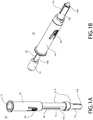
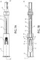
- FIGs. 1A and 1B each depicts a perspective view of a child resistant safety device 10 for an oral dosage form 12.
- the child resistant safety device 10 is shown in a retracted configuration wherein the oral dosage form 12 is shielded by a child resistant cover 14.
- the child resistant safety device 10 is shown in a deployed configuration wherein the oral dosage form 12 is exposed through an opening 17 in the cover 14 for the purpose of consumption.
- the child resistant safety device 10 is capable of moving between the retracted configuration of FIG. 1A and the deployed configuration of FIG. 1B by a user of the device 10.
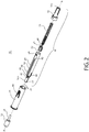
- FIG. 2 depicts an exploded view of the safety device 10 of FIGs. 1A and 1B .
- the safety device 10 generally comprises a shaft assembly 16 and a safety cover 14 that is retractably mounted to the shaft assembly 16.
- the proximal end 16a of the shaft assembly 16 is configured to be grasped by a user, and the distal end 16b of the shaft assembly 16 is configured to fixedly receive the oral dosage form 12.
- the oral dosage form 12 is not necessarily a component of the safety device 10.
- the components of the safety device 10 may be formed from any materials known to those of ordinary skill in the art, such as plastic or metal, for example.
- the spring 23 of the safety device 10 may be formed from any resilient material, such as spring steel, for example.
- the shaft assembly 16 includes a two-piece shaft, having a proximal shaft portion 18 that is fixed to a distal shaft portion 20, and a captivated plunger 21 that is loaded by a spring 23 and is capable of translation within an opening formed through the two-piece shaft.
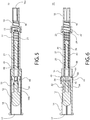
- the proximal shaft portion 18 includes a substantially tubular body having an opening extending along its entire length such that both ends of the tubular body are open. As shown in FIG. 5 , a circumferential shoulder 13 is formed on the distal end of the proximal shaft portion 18. In an assembled configuration of the shaft assembly 16, the proximal end of the distal shaft portion 20 is configured to be seated on the shoulder of the proximal shaft portion 18, as best shown in FIGs. 5 and 6 . According to this exemplary embodiment, the shaft portions 18 and 20 of the shaft assembly 16 are separate components that are fixed to each other, however, the shaft portions 18 and 20 may be combined together into a single unitary component.
- a circumferential shoulder 46 is formed on the interior surface of the proximal shaft portion 18.
- the proximal end of the spring 23 is configured to be seated on the shoulder 46 of the proximal shaft portion 18.
- a radially-inwardly extending protrusion 22 is defined on the distal end of the proximal shaft portion 18 (see FIG. 6 ).
- the radially-inwardly extending protrusion 22 is press-fit into a rectangular slot 24 that is defined on the exterior surface of the proximal end of the distal shaft portion 20.
- the shaft portions 18 and 20 are not readily releasable from each other.
- the opening at the proximal end 16a of the proximal shaft portion 18 is sized to accommodate the proximal end of the plunger 21 when the plunger 21 is in its fully-deployed position, as shown in FIG. 9B .
- the distal shaft portion 20 of the shaft assembly 16 includes a substantially tubular body having an opening extending along its entire length such that both ends of the tubular body are open.
- At least one guiding rib 28 extends from the outer surface of the distal shaft portion 20 in an axial direction along the longitudinal axis 'A.' The guiding ribs 28 are located toward the distal end of the distal shaft portion 20. The guiding ribs 28 are positioned on opposite sides of the distal shaft portion 20.
- the guiding ribs 28 are slidingly positioned within corresponding slots 30 (see FIGs. 2 and 13 ) that are defined on the interior surface of the safety cover 14.
- the guiding ribs 28 and the slots 30 help guide the shaft assembly 16 as it translates with respect to the safety cover 14, or vice versa.
- the guiding ribs 28 and the slots 30 also prevent rotation of the shaft assembly 16 with respect to the safety cover 14, or vice versa, about the longitudinal axis 'A.'
- the distal end 16b of the distal shaft portion 20 includes a necked-down portion 32.
- the post 34 of the oral dosage form 12 is fixedly positioned in the opening that passes through the necked-down portion 32.
- the post 34 of the oral dosage form 12 and the necked-down portion 32 may be fixed together by a sonic weld, an interference fit or an adhesive, for example, to prevent inadvertent detachment of the oral dosage form 12 from the safety device 10.
- At least one slot 36 is defined along the central portion of the distal shaft portion 20. According to this exemplary embodiment, as best shown in FIG. 6 , two slots 36 are positioned opposite one another on the distal shaft portion 20. Although only one slot 36 will be described hereinafter, it should be understood that the other slot 36 is both structurally and functionally equivalent.
- the slot 36 is defined through the entire thickness of the side wall of the distal shaft portion 20. The width 'W' of the slot 36 is constant along its length.
- an opening 40 is provided at the distal end of the slot 36, and a wall 42 is provided at the proximal end of the slot 36.
- the slot 36 extends between the opening 40 and the wall 42.
- depressible and resilient tabs 44 on the cover 14 are both removably and slidably positioned with respective slots 36 on the distal shaft portion 20.
- a hole 41 is defined on the outer surface of the distal shaft portion 20 at the entrance of each slot 36, i.e., at a location that is directly distal of the opening 40 of each slot 36.
- the hole 41 accommodates translation of a respective tab 44 of the cover 14 in a radial direction toward the longitudinal axis 'A' of the safety device 10.
- the hole 41 passes through the entirety of the distal shaft portion 20.
- a plunger 21 of the shaft assembly 16 is slideably positioned within an interior chamber 49 of the shaft assembly 16.
- a resilient compression spring 23 bears on the plunger 21 and the proximal shaft portion 18. More particularly, the spring 23 is mounted between a shoulder 46 (see FIG. 6 ) that is formed on the interior surface of the proximal shaft portion 18 and another shoulder 48 that is formed on the exterior surface of the distal end of the plunger 21.
- the spring 23 biases the plunger 21 in the distal direction against the cover 14, thereby biasing the cover 14 toward its retracted position that is shown in FIGs. 3-6 .
- the spring rate of the spring 23 is selected such that it is low enough to enable easy translation of the plunger 21 by the user, yet high enough to return the plunger 21 to its retracted position shown in FIGs. 5 and 6 .
- the device 10 may incorporate a damping means to prevent the device 10 from moving between the deployed and retracted positions too rapidly.
- the damping means may be a fluid 51 (shown schematically in FIG. 5 ), such as a food-grade grease, that is provided in the interior chamber 49 of the shaft assembly 16.
- the device 10 may be modified by (i) mounting an O-ring (not shown) at the proximal end of the plunger 21 to contact the revolved interior surface of the shaft assembly 16, and (ii) closing at least the proximal end 16a of the shaft assembly 16.
- the damping means may also be an O-ring (not shown) that is mounted at the proximal end of the plunger 21 to contact the revolved interior surface of the shaft assembly 16.
- the O-ring would provide a friction force that opposes the force of the spring 23 as the spring 23 automatically translates the device 10 from a deployed position to a retracted position once the device 10 is released by the user.
- the damping means may also be a second spring that is mounted to the plunger 21 to bias the plunger 21 in a proximal direction.
- the spring rate of the second spring would be lower than that of the spring 23 so that the device 10 can automatically return to its retracted position once the device 10 is released by the user.
- the damping means is an optional feature of the invention and it may be omitted entirely.
- the plunger 21 is sandwiched between the spring 23 and the cover 14.
- the distal end 52 (see FIG. 2 ) of the plunger 21 bears on the proximal end of the cover 14.
- the proximal end of the cover 14 pushes the plunger 21 in the proximal direction against the force of the spring 23.
- the spring 23 urges the plunger 21 in a distal direction against the cover 14, thereby causing the cover 14 to also move in the distal direction.
- the child resistant cover 14 of the safety device 10 is best shown in FIGs. 1A , 2 and 10-13 . Detailed views of the cover 14 are shown in FIGs. 10-13 .
- the cover 14 includes a tubular body defining an opening 17 at its distal end through which the medicinal agent 12 can be exposed, and at least one resiliently moveable tab 44 that is formed on the body.
- the cover 14 is a unitary component, according to this embodiment.
- the cover 14 includes two tabs 44 that are defined on opposing sides of the body.
- the structure and function of only one of the tabs 44 will be described hereinafter, however, it should be understood that the structure and function of both tabs 44 are the same.
- the tab 44 of the safety cover 14 interacts with the slot 36 that is formed on the shaft assembly 16 to releasably lock the safety device 10 in the retracted position.
- the tab 44 may also be referred to herein as a releasable locking mechanism.
- the tab 44 is configured to "child resistant" the device 10 because the tab 44 must be depressed inwardly toward the longitudinal axis 'A' (see FIG. 12 ) before the cover 14 can be translated with respect to the shaft assembly 16 (or vice versa) to expose the medicinal agent 12.
- the tab 44 includes an outer surface 56 that is capable of being contacted by the finger of a user, a relatively narrow rib 58 depending from the outer surface 56 that extends in a radial direction toward the longitudinal axis 'A,' and a wide stop 60 that is defined on the end of the narrow rib 58.
- the width 'W1' of the rib 58 is less than the width 'W' (see FIG. 4 ) of the slot 36, whereas the width 'W2' of the stop 60 is greater than the width 'W' of the slot 36. Accordingly, in the assembled form of the device 10, the rib is 58 capable of translating in the slot 36, whereas the stop 60 is not able to be positioned within the slot 36.
- the stop 60 In the retracted position of the device 10, the stop 60 is registered with the opening 40 of the slot 36. This is referred to herein as the locked configuration of the tab 44.
- the stop 60 abuts against a bearing surface 54 at the distal end 16b of the shaft assembly 16 because the width 'W2' of the stop 60 is greater than the width 'W' of the opening 40 of the slot 36. Thus, the stop 60 can not pass through the opening 40.
- the abutment between the stop 60 and the opening 40 prevents the cover 14 from translating in a proximal direction with respect to the shaft assembly 16, and prevents the shaft assembly 16 from translating in a proximal direction with respect to the cover 14.
- the cover 14 in a retracted position of the device 10, the cover 14 is incapable of translating with respect to the shaft assembly 16 (and vice versa), thereby preventing access to the medicinal agent 12 that is contained within the interior of the cover 14.
- the narrow rib 58 In the retracted position of the device, the narrow rib 58 does not register with the slot 36, as shown in FIG. 6 .
- FIGS. 6 , 7B , 8B and 9B depict successive movement of the safety device from a retracted position to the deployed position.
- the safety device 10 is ordinarily stored in the retracted position that is shown in FIG. 6 .
- the cover 14 can not be translated with respect to the shaft assembly 16 (and vice versa) because the stop 60 of the tab 44 is lodged in the hole 41 of the distal shaft portion 20 and is sandwiched between the opening 40 of the slot 36 and the surface 70 (see FIG. 6 and 17 ).
- the stop 60 is wider than the opening 40, and thus can not enter the opening 40.
- FIG. 7B depicts the depressed position of the tab 44. Depressing the tab 44 towards the longitudinal axis 'A' registers the rib 58 of the tab 44 with the opening 40 of the slot 36, and moves the stop 60 into the hole 41 that is formed on the distal shaft portion 20.
- the width of the rib 58 is less than the width of the slot 36, thus, the rib 58 can translate along the slot 36.
- FIGs. 7B , 8B and 9B depict the sequential movement of the safety device 10 from a retracted position to the deployed position.
- the cover 14 can be translated in the proximal direction while the shaft assembly 16 remains stationary.
- the shaft assembly 16 can be translated in a distal direction while the cover 14 remains stationary.
- the cover 14 can be translated in the proximal direction while the shaft assembly 16 is translated in a distal direction. Any of the aforementioned translational movements will produce the same result, i.e., the safety device 10 will be moved to the deployed position of FIG. 9B .
- the description that follows assumes that the cover 14 is translated in the proximal direction while the shaft assembly 16 remains stationary.
- the rib 58 of the tab 44 is registered with the opening 40 of the slot 36. Thereafter, the cover 14 is translated in a proximal direction along the longitudinal axis 'A' against the force of the spring 23 while the shaft assembly 16 remains stationary. As the cover 14 is translated in the proximal direction toward the position shown in FIG. 8B , the rib 58 slides in the slot 36 while the stop 60 of the tab 44 rides along the revolved interior surface of the distal shaft portion 20. At this point, the tab 44 can be released by the user. Upon releasing the tab 44, the rib 58 remains in the slot 36 while the stop 60 continues to bear on the revolved interior surface of the distal shaft portion 20. The stop 60 does not prevent translation of the cover 14 once the stop 60 is positioned against the revolved interior surface of the distal shaft portion 20.
- the proximal end of the stop 60 bears on the distal end surface 52 of the plunger 21 thereby urging the plunger 21 in the proximal direction against the force of the spring 23.
- the cover 14 is translated against the force of the spring 23.
- the spring 23 is compressed between the plunger 21 and the proximal shaft portion 18 as the user translates the cover 14 in the proximal direction.
- the user translates the cover 14 in a proximal direction along the longitudinal axis 'A' until the rib 58 contacts the end wall 42 of the slot 36 at which point the cover 14 is prevented from moving further in the proximal direction.
- the device 10 is in the deployed position that is shown in FIG. 9B .
- the cover 14 In the deployed position of the device 10, the cover 14 is spaced from the medicinal agent 12 and the medicinal agent 12 is exposed and available to the user.
- the user releases the cover 14.
- the spring 23 expands and causes the cover 14 to automatically return to its retracted position shown in FIG. 6 .
- the damping agent 51 would slow the return of the cover 14 to the retracted position.
- the resilient tab 44 moves outward and away from the longitudinal axis 'A' and returns to its position shown in FIG. 6 . Thereafter, the device 10 may be moved back to the deployed position, as previously described, if so desired.
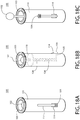
- FIGs. 18A-18C depict another safety device 100 for a medicinal agent, according to a second exemplary embodiment of the invention.
- the safety device 100 generally includes a hollow cylindrical tube 101 defining an opening 103, a spring-loaded shaft 108 that is moveably positioned within the interior of the tube 101, a medicinal agent 102 that is fixedly attached to a distal end of the shaft 108, and a child resistant lever 104 that is fixedly attached to a proximal end of the spring-loaded shaft 108.
- the child resistant lever 104 is provided for moving the shaft 108 and the medicinal agent 102 between the retracted position of FIGs. 18A and 18B and the deployed position of FIG. 18C .
- the user In a retracted position of the device 100, the user is unable to consume the medicinal agent 102, whereas, in the deployed position of the device 100, the medicinal agent 102 is available to the user for consumption.
- a spring 106 is positioned around the shaft 108 between an interior shoulder 110 of the tube 101 and a leg 105 extending from the lever 104.
- the leg 105 is fixedly connected between the lever 104 and the proximal end of the shaft 108.
- the spring 106 is positioned to bias the lever 104, the shaft 108 and the medicinal agent 102 in a downward direction (as viewed in FIGs. 18A-18C ) toward the retracted position shown in FIG. 18B .
- a ramp 114 is formed on the outer surface of the tube 101.
- a user must pull the lever 104 away from the tube 101 to clear the ramp 114 before advancing the lever 104 (along with the medicinal agent 102 that is indirectly attached to the lever 104) in an upward direction toward the deployed position shown in FIG. 18C .
- the spring 106 automatically urges the lever 104, the shaft 108 and the medicinal agent 102 in a downward direction to the retracted position shown in FIG. 14B .
- the force of the spring 106 is sufficient to move the lever 104 in the downward direction along the angled surface of the ramp 114.
- the lever 104 ultimately comes to rest in the position shown in FIG. 18B .
- the ramp 114 serves as the child resistant feature of the device 100. Those of ordinary skill in the art will recognize that other ways exist to child resistant the device 100.
Landscapes
- Health & Medical Sciences (AREA)
- Life Sciences & Earth Sciences (AREA)
- Animal Behavior & Ethology (AREA)
- General Health & Medical Sciences (AREA)
- Public Health (AREA)
- Veterinary Medicine (AREA)
- Pharmacology & Pharmacy (AREA)
- Chemical & Material Sciences (AREA)
- Medicinal Chemistry (AREA)
- Epidemiology (AREA)
- Emergency Medicine (AREA)
- Engineering & Computer Science (AREA)
- Mechanical Engineering (AREA)
- Neurosurgery (AREA)
- Bioinformatics & Cheminformatics (AREA)
- Biomedical Technology (AREA)
- Neurology (AREA)
- Pain & Pain Management (AREA)
- Chemical Kinetics & Catalysis (AREA)
- General Chemical & Material Sciences (AREA)
- Nuclear Medicine, Radiotherapy & Molecular Imaging (AREA)
- Organic Chemistry (AREA)
- Infusion, Injection, And Reservoir Apparatuses (AREA)
- Medical Preparation Storing Or Oral Administration Devices (AREA)
- Medicines That Contain Protein Lipid Enzymes And Other Medicines (AREA)
- Pharmaceuticals Containing Other Organic And Inorganic Compounds (AREA)
Description
- The present invention relates to a child resistant safety cover for an oral dosage form, particularly an oral dosage form that is equipped with a holder or a handle.
- Several drug products currently on the market are provided in a form for oral administration, wherein the oral drug form is equipped and used with a holder or handle. A user of such an oral drug product could potentially remove it from its packaging and leave it unattended with the drug product exposed and accessible to another person, e.g., a child. It would be beneficial to provide a safety device for such a drug product to prevent another person, particularly a child, from inadvertently accessing the medicinal agent.
-
US 2,017,783 discloses a capsule administering device for holding a capsule and administering it into the throat of an animal. -
US 2,469,399 discloses a disposable dispensing device for dispensing a measured amount of a liquid to a patient. -
US 2009/0142727 A1 discloses a device for delivering medicinal implants into a dental pocket of a patient. -
US 7,744,558 discloses a pill plunger for administering medication in pill, powder and liquid form. -
US 4,474,308 discloses a tablet or pill ejector consisting of at least three detachably secured sections in the general shape of a pen. The front end of the device is provided with a hole communicating with axially aligned bores formed longitudinally in the sections and through which a pill may be ejected quickly. An ejector rod is provided in the bores adapted to move from a cocked position to a released position wherein it passes instantly through a pill retaining member located in the front section of the device. Cocking and trigger mechanisms are provided. In an alternate embodiment the front section is provided with a revolvable barrel adapted to contain a plurality of pills for ejection. The rear end of the device may be provided with a storage compartment and cap. -
US 5,399,162 discloses an automatic balling gun which includes an elongated member having a tubular profile which is easily operated and manipulated by the single hand of the user. A release assembly is mounted along the length of the tubular member to dispense medicine orally to an animal by merely depressing a plunger. A knob is provided on a proximal end of the automatic balling gun which facilitates cocking the gun and loading a dispensing chamber thereof with a capsule or pill to be dispensed. The automatic balling gun can then be inserted into the animal to be treated followed by depressing the plunger on the release assembly to dispense the medication from the gun. - The present invention provides a child resistant safety device for an oral dosage form as recited in the claims.
- According to some embodiments of these aspects of the invention, the position (or configuration) of the device or retractable oral dosage form, which is referred to herein as a "retracted position" (or "retracted configuration") corresponds to a "retracted/locked position," (or "retracted/locked configuration"), wherein a releasable locking mechanism prevents movement to the deployed position until and unless the locking mechanism is released.
- The invention is best understood from the following detailed description when read in connection with the accompanying drawing. It is emphasized that, according to common practice, the various features of the drawing are not to scale. Included in the drawing are the following figures:
-
FIG. 1A depicts a perspective view of a safety device for an oral dosage form according to a first exemplary embodiment of the invention, wherein the safety device is shown in a retracted configuration whereby the oral dosage form is shielded by a child resistant cover. -
FIG. 1B depicts a perspective view of the safety device ofFIG. 1A shown in a deployed configuration whereby the oral dosage form is exposed. -
FIG. 2 depicts an exploded view of the safety device ofFIGs. 1A and 1B . -
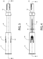
FIGs. 3 and 4 depict right side elevation and front elevation views, respectively, of the safety device ofFIGs. 1A and 1B shown in a retracted configuration. -
FIG. 5 depicts a cross-sectional side elevation view of the retracted safety device ofFIG. 3 taken along the lines 5-5. -
FIG. 6 depicts a cross-sectional side elevation view of the retracted safety device ofFIG. 4 taken along the lines 6-6. -
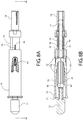
FIGs. 7A and 7B depict front elevation and cross-sectional views, respectively, of the safety device ofFIG. 6 with the tabs of the child resistant cover shown in a depressed position. -
FIGs. 8A and 8B depict elevation and cross-sectional views, respectively, of the safety device ofFIGs. 7A and 7B with the tabs of the child resistant cover shown depressed and the child resistant cover slid in a proximal direction. -
FIGs. 9A and 9B depict elevation and cross-sectional views, respectively, of the safety device ofFIGs. 8A and 8B with the tabs of the child resistant cover depressed and the child resistant cover slid further in the proximal direction such that the oral dosage form is exposed. -
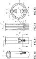
FIGs. 10 and 11 depict perspective and side elevation views, respectively, of the child resistant cover of the safety device ofFIGs. 1-9 . -
FIG. 12 depicts a cross-sectional side elevation view of the child resistant cover ofFIG. 11 taken along the lines 12-12. -
FIG. 13 depicts an enlarged cross-sectional plan view of the child resistant cover ofFIG. 11 taken along the lines 13-13. -
FIGs. 14-16 depict perspective, right side and front elevation views, respectively, of the distal shaft portion of the safety device ofFIGs. 1-9 . -
FIG. 17 depicts a cross-sectional side elevation view of the distal shaft portion ofFIG. 15 taken along the lines 17-17. -
FIG. 18A depicts a front perspective view of a safety device for an oral dosage form according to a second exemplary embodiment of the invention, wherein the safety device is shown in a retracted configuration whereby the oral dosage form is shielded by a child resistant cover of the safety device. -
FIG. 18B depicts a right side perspective view of the safety device ofFIG. 18A , wherein the internal mechanisms of the safety device are shown in phantom lines. -
FIG. 18C depicts a front perspective view of the safety device ofFIG. 18A , - This invention will now be described with reference to several embodiments selected for illustration in the drawings. It will be appreciated that the scope of the invention is are not limited to the illustrated embodiments.
- A first exemplary embodiment of a child resistant safety device for an oral dosage form comprising a medicinal agent is depicted in
FIGs. 1A-17 , and a second exemplary embodiment of a child resistant safety device for an oral dosage form comprising a medicinal agent is depicted inFIGs. 18A through 18C . - The expression "child resistant," as used herein, relates to special packaging that is used to reduce the risk of children ingesting dangerous items or substances. Packaging designated as "child resistant" is typically subject to the rigorous testing set out in the regulatory scheme of 16 C.F.R. § 1700, which provides specific protocols for performance testing with actual children, to determine whether certain packaging can be opened. The oral dosage form described herein may comprise, for example, a solid, or a permeable or semi-permeable matrix capable of drug elution, form. The oral dosage form may be, for example, a lozenge, a pill, a tablet, or other oral dosage form capable of drug delivery via the buccal or sublingual route (transmucosal), in particular, in a form that can be equipped and used with a holders or handle.
- The oral dosage form comprises at least one medicinal agent. While at least one medicinal agent is required, it is contemplated that multiple medicinal agents may also be used. The term "medicinal agent" refers generally to drug products. Such medicinal agents may include pharmaceutical ingredients, vitamins, minerals, and dietary supplements and combinations thereof. Pharmaceutical ingredients may include, for example, antacids, analgesics, stimulants, sleep aids, hypnotics, antipyretics, antimicrobials, anxiolytics, laxatives, antidepressants, antidiuretics, antiflatuents, antispasmodics, anti-inflammatory, antibiotics, diuretics, anorexics, antihistamines, antiasthmatics, antidiuretics, antiflatuents, antimigraine agents, antispasmodics, sedatives, antihyperactives, antihypertensives, tranquilizers, decongestants, immunosuppressants, anticancers, antivirals, antiparasitics, antifungals, antiemetics, antidepressants, antiepileptics, local anesthetics, vasoactive agents, antiasthmatics, skeletal muscle relaxants, drugs for parkinsonism, antipsychotics, hematopoietic growth factors, antihyperlipidemics, anticoagulants, fibrinolytics, antithrombotics, hormones, therapeutic proteins and peptides, antiarrhythmia, antiangina, beta blockers and combinations thereof.
- Also included as medicinal agents that may be administered using the present invention are the drugs and pharmaceutically active ingredients described in Mantelle,
U.S. Pat. No. 5,234,957 , incolumns 18 through 21. - According to some embodiments of the invention, the medicinal agent is a pharmaceutical agent having a high likelihood of abuse by people. In some embodiments of the invention, the medicinal agent is a pain medication such as a narcotic or non-narcotic analgesic, for example, as listed on pages THER-2 and THER-3 of The Merck Index, 13th Ed., Published by Merck & Co., Inc., of Whitehouse Station, N.J., copyright 2001.
- Suitable narcotic analgesics include, for example, analgesics, pain relievers, opioids, such as, for example, oxycodone, codeine, hydrocodone, morphine, hydromorphone, oxymorphone, methadone, propoxyphene, meperidine, fentanyl, buprenorphine, butorphanol, dezocine, levomethadyl acetate, levorphanol, nalbuphine, pentazocine, remifentanil, sufentanil, tramadol; stimulants, such as, for example, amphetamine, methamphetamine, dexamphetamine, methylphenidate, dexmethylphenidate, and pemoline; sedative / hypnotics, such as, for example, barbiturates, such as, for example, amobarbital, aprobarbital, butabarbital, mephobarbital, phenobarbital, secobarbital; benzodiazepines, such as, for example, alprazolam, clonazepam, diazepam, estazolam, flurazepam, halazepam, lorazepam, midazolam, quazepam, temazepam, triazolam, prazepam, and oxazepam; and eugeroics, such as, for example, modafinil and armodafinil. Particularly suitable medicinal agents include oxycodone, fentanyl and hydromorphone. Salts of all of the medicinal agents listed above are also contemplated, as are their stereogenic isomers, polymorphs and solvates.
- The medicinal agent may be administered via transmucosal or sublingual routes.
- Referring now to the first exemplary embodiment of the child
resistant safety device 10,FIGs. 1A and 1B each depicts a perspective view of a childresistant safety device 10 for anoral dosage form 12. InFIGs. 1A and3-6 , the childresistant safety device 10 is shown in a retracted configuration wherein theoral dosage form 12 is shielded by a childresistant cover 14. InFIG. 1B , the childresistant safety device 10 is shown in a deployed configuration wherein theoral dosage form 12 is exposed through anopening 17 in thecover 14 for the purpose of consumption. As will be described hereinafter, the childresistant safety device 10 is capable of moving between the retracted configuration ofFIG. 1A and the deployed configuration ofFIG. 1B by a user of thedevice 10. -
FIG. 2 depicts an exploded view of thesafety device 10 ofFIGs. 1A and 1B . As best shown inFIG. 2 , thesafety device 10 generally comprises ashaft assembly 16 and asafety cover 14 that is retractably mounted to theshaft assembly 16. Theproximal end 16a of theshaft assembly 16 is configured to be grasped by a user, and thedistal end 16b of theshaft assembly 16 is configured to fixedly receive theoral dosage form 12. It should be understood that theoral dosage form 12 is not necessarily a component of thesafety device 10. The components of thesafety device 10 may be formed from any materials known to those of ordinary skill in the art, such as plastic or metal, for example. Thespring 23 of thesafety device 10 may be formed from any resilient material, such as spring steel, for example. - Referring now to
FIGs. 1A-6 , theshaft assembly 16 includes a two-piece shaft, having aproximal shaft portion 18 that is fixed to adistal shaft portion 20, and a captivatedplunger 21 that is loaded by aspring 23 and is capable of translation within an opening formed through the two-piece shaft. - Referring now to the individual components of the
shaft assembly 16, theproximal shaft portion 18 includes a substantially tubular body having an opening extending along its entire length such that both ends of the tubular body are open. As shown inFIG. 5 , acircumferential shoulder 13 is formed on the distal end of theproximal shaft portion 18. In an assembled configuration of theshaft assembly 16, the proximal end of thedistal shaft portion 20 is configured to be seated on the shoulder of theproximal shaft portion 18, as best shown inFIGs. 5 and 6 . According to this exemplary embodiment, theshaft portions shaft assembly 16 are separate components that are fixed to each other, however, theshaft portions - As shown in
FIG. 6 , acircumferential shoulder 46 is formed on the interior surface of theproximal shaft portion 18. In an assembled configuration of theshaft assembly 16, the proximal end of thespring 23 is configured to be seated on theshoulder 46 of theproximal shaft portion 18. - A radially-inwardly extending
protrusion 22 is defined on the distal end of the proximal shaft portion 18 (seeFIG. 6 ). In an assembled form of theshaft assembly 16, the radially-inwardly extendingprotrusion 22 is press-fit into arectangular slot 24 that is defined on the exterior surface of the proximal end of thedistal shaft portion 20. Theshaft portions proximal end 16a of theproximal shaft portion 18 is sized to accommodate the proximal end of theplunger 21 when theplunger 21 is in its fully-deployed position, as shown inFIG. 9B . - As best shown in
FIGs. 2 and14-17 , thedistal shaft portion 20 of theshaft assembly 16 includes a substantially tubular body having an opening extending along its entire length such that both ends of the tubular body are open. At least one guidingrib 28 extends from the outer surface of thedistal shaft portion 20 in an axial direction along the longitudinal axis 'A.' The guidingribs 28 are located toward the distal end of thedistal shaft portion 20. The guidingribs 28 are positioned on opposite sides of thedistal shaft portion 20. - In an assembled form of the
safety device 10, the guidingribs 28 are slidingly positioned within corresponding slots 30 (seeFIGs. 2 and13 ) that are defined on the interior surface of thesafety cover 14. The guidingribs 28 and theslots 30 help guide theshaft assembly 16 as it translates with respect to thesafety cover 14, or vice versa. The guidingribs 28 and theslots 30 also prevent rotation of theshaft assembly 16 with respect to thesafety cover 14, or vice versa, about the longitudinal axis 'A.' - The
distal end 16b of thedistal shaft portion 20 includes a necked-down portion 32. Thepost 34 of theoral dosage form 12 is fixedly positioned in the opening that passes through the necked-down portion 32. Thepost 34 of theoral dosage form 12 and the necked-down portion 32 may be fixed together by a sonic weld, an interference fit or an adhesive, for example, to prevent inadvertent detachment of theoral dosage form 12 from thesafety device 10. - At least one
slot 36 is defined along the central portion of thedistal shaft portion 20. According to this exemplary embodiment, as best shown inFIG. 6 , twoslots 36 are positioned opposite one another on thedistal shaft portion 20. Although only oneslot 36 will be described hereinafter, it should be understood that theother slot 36 is both structurally and functionally equivalent. Theslot 36 is defined through the entire thickness of the side wall of thedistal shaft portion 20. The width 'W' of theslot 36 is constant along its length. - As best shown in
FIGs. 2 ,8B and16 , anopening 40 is provided at the distal end of theslot 36, and awall 42 is provided at the proximal end of theslot 36. Thus, theslot 36 extends between theopening 40 and thewall 42. As will be described in greater detail with respect toFIGs. 6 and7B , depressible andresilient tabs 44 on thecover 14 are both removably and slidably positioned withrespective slots 36 on thedistal shaft portion 20. - A
hole 41 is defined on the outer surface of thedistal shaft portion 20 at the entrance of eachslot 36, i.e., at a location that is directly distal of theopening 40 of eachslot 36. As will be described in greater detail with respect toFIGs. 6 and7B , thehole 41 accommodates translation of arespective tab 44 of thecover 14 in a radial direction toward the longitudinal axis 'A' of thesafety device 10. According to this exemplary embodiment, thehole 41 passes through the entirety of thedistal shaft portion 20. - Referring now to
FIGs. 2 ,5 and 6 , aplunger 21 of theshaft assembly 16 is slideably positioned within aninterior chamber 49 of theshaft assembly 16. Aresilient compression spring 23 bears on theplunger 21 and theproximal shaft portion 18. More particularly, thespring 23 is mounted between a shoulder 46 (seeFIG. 6 ) that is formed on the interior surface of theproximal shaft portion 18 and anothershoulder 48 that is formed on the exterior surface of the distal end of theplunger 21. Thespring 23 biases theplunger 21 in the distal direction against thecover 14, thereby biasing thecover 14 toward its retracted position that is shown inFIGs. 3-6 . The spring rate of thespring 23 is selected such that it is low enough to enable easy translation of theplunger 21 by the user, yet high enough to return theplunger 21 to its retracted position shown inFIGs. 5 and 6 . - The
device 10 may incorporate a damping means to prevent thedevice 10 from moving between the deployed and retracted positions too rapidly. The damping means may be a fluid 51 (shown schematically inFIG. 5 ), such as a food-grade grease, that is provided in theinterior chamber 49 of theshaft assembly 16. To prevent the escapement of the fluid 51 from theinterior chamber 49, thedevice 10 may be modified by (i) mounting an O-ring (not shown) at the proximal end of theplunger 21 to contact the revolved interior surface of theshaft assembly 16, and (ii) closing at least theproximal end 16a of theshaft assembly 16. - The damping means may also be an O-ring (not shown) that is mounted at the proximal end of the
plunger 21 to contact the revolved interior surface of theshaft assembly 16. The O-ring would provide a friction force that opposes the force of thespring 23 as thespring 23 automatically translates thedevice 10 from a deployed position to a retracted position once thedevice 10 is released by the user. - The damping means may also be a second spring that is mounted to the
plunger 21 to bias theplunger 21 in a proximal direction. One of ordinary skill in the art will recognize that the spring rate of the second spring would be lower than that of thespring 23 so that thedevice 10 can automatically return to its retracted position once thedevice 10 is released by the user. The damping means is an optional feature of the invention and it may be omitted entirely. - The
plunger 21 is sandwiched between thespring 23 and thecover 14. The distal end 52 (seeFIG. 2 ) of theplunger 21 bears on the proximal end of thecover 14. When a user translates thecover 14 in a proximal direction (thereby moving thedevice 10 from the retracted position to the deployed position), the proximal end of thecover 14 pushes theplunger 21 in the proximal direction against the force of thespring 23. When a user releases the device 10 (causing thedevice 10 to move from the deployed position to the retracted position), thespring 23 urges theplunger 21 in a distal direction against thecover 14, thereby causing thecover 14 to also move in the distal direction. - The child
resistant cover 14 of thesafety device 10 is best shown inFIGs. 1A ,2 and10-13 . Detailed views of thecover 14 are shown inFIGs. 10-13 . Referring now to those figures, thecover 14 includes a tubular body defining anopening 17 at its distal end through which themedicinal agent 12 can be exposed, and at least one resilientlymoveable tab 44 that is formed on the body. Thecover 14 is a unitary component, according to this embodiment. - According to this exemplary embodiment, the
cover 14 includes twotabs 44 that are defined on opposing sides of the body. The structure and function of only one of thetabs 44 will be described hereinafter, however, it should be understood that the structure and function of bothtabs 44 are the same. - The
tab 44 of thesafety cover 14 interacts with theslot 36 that is formed on theshaft assembly 16 to releasably lock thesafety device 10 in the retracted position. Thetab 44 may also be referred to herein as a releasable locking mechanism. Thetab 44 is configured to "child resistant" thedevice 10 because thetab 44 must be depressed inwardly toward the longitudinal axis 'A' (seeFIG. 12 ) before thecover 14 can be translated with respect to the shaft assembly 16 (or vice versa) to expose themedicinal agent 12. - Referring now to
FIGs. 12 and 13 , thetab 44 includes anouter surface 56 that is capable of being contacted by the finger of a user, a relativelynarrow rib 58 depending from theouter surface 56 that extends in a radial direction toward the longitudinal axis 'A,' and awide stop 60 that is defined on the end of thenarrow rib 58. The width 'W1' of therib 58 is less than the width 'W' (seeFIG. 4 ) of theslot 36, whereas the width 'W2' of thestop 60 is greater than the width 'W' of theslot 36. Accordingly, in the assembled form of thedevice 10, the rib is 58 capable of translating in theslot 36, whereas thestop 60 is not able to be positioned within theslot 36. - In the retracted position of the
device 10, thestop 60 is registered with theopening 40 of theslot 36. This is referred to herein as the locked configuration of thetab 44. Thestop 60 abuts against a bearingsurface 54 at thedistal end 16b of theshaft assembly 16 because the width 'W2' of thestop 60 is greater than the width 'W' of theopening 40 of theslot 36. Thus, thestop 60 can not pass through theopening 40. The abutment between thestop 60 and theopening 40 prevents thecover 14 from translating in a proximal direction with respect to theshaft assembly 16, and prevents theshaft assembly 16 from translating in a proximal direction with respect to thecover 14. Thus, in a retracted position of thedevice 10, thecover 14 is incapable of translating with respect to the shaft assembly 16 (and vice versa), thereby preventing access to themedicinal agent 12 that is contained within the interior of thecover 14. In the retracted position of the device, thenarrow rib 58 does not register with theslot 36, as shown inFIG. 6 . - Depressing the
tab 44 towards the longitudinal axis 'A' registers therib 58 with theopening 40 of theslot 36, and moves thestop 60 into thehole 41 that is formed on thedistal shaft portion 20. Thereafter, therib 58 can translate along the length of theslot 36 upon translating thecover 14 with respect to the shaft assembly (and vice versa), while thestop 60 travels along the interior surface of thedistal shaft portion 20. This is referred to herein as the unlocked configuration of thetab 44. - Referring now to the operation of the
safety device 10,FIGS. 6 ,7B ,8B and9B depict successive movement of the safety device from a retracted position to the deployed position. Beginning atFIG. 6 , thesafety device 10 is ordinarily stored in the retracted position that is shown inFIG. 6 . In the retracted position inFIG. 6 , thecover 14 can not be translated with respect to the shaft assembly 16 (and vice versa) because thestop 60 of thetab 44 is lodged in thehole 41 of thedistal shaft portion 20 and is sandwiched between the opening 40 of theslot 36 and the surface 70 (seeFIG. 6 and17 ). As described previously, thestop 60 is wider than theopening 40, and thus can not enter theopening 40. - To move the
safety device 10 from the retracted position shown inFIG. 6 to the deployed position shown inFIG. 9B , thetab 44 must first be depressed by the user toward the longitudinal axis A. Although the operation of only onetab 44 is described in this section, it should be understood that theother tab 44 operates in the same fashion. This step of the process represents the "child resistant" aspect of thedevice 10.FIG. 7B depicts the depressed position of thetab 44. Depressing thetab 44 towards the longitudinal axis 'A' registers therib 58 of thetab 44 with theopening 40 of theslot 36, and moves thestop 60 into thehole 41 that is formed on thedistal shaft portion 20. As noted previously, the width of therib 58 is less than the width of theslot 36, thus, therib 58 can translate along theslot 36. Once thetab 44 is depressed, as shown inFIG. 7B , thecover 14 is capable of translating along the longitudinal axis 'A' with respect to the shaft assembly 16 (and vice versa). -
FIGs. 7B ,8B and9B depict the sequential movement of thesafety device 10 from a retracted position to the deployed position. After thetab 44 is depressed, there are three different ways to translate thesafety device 10 to the deployed position. First, thecover 14 can be translated in the proximal direction while theshaft assembly 16 remains stationary. Second, theshaft assembly 16 can be translated in a distal direction while thecover 14 remains stationary. Third, thecover 14 can be translated in the proximal direction while theshaft assembly 16 is translated in a distal direction. Any of the aforementioned translational movements will produce the same result, i.e., thesafety device 10 will be moved to the deployed position ofFIG. 9B . The description that follows assumes that thecover 14 is translated in the proximal direction while theshaft assembly 16 remains stationary. - Once the
tab 44 is depressed, as shown inFIG. 7B , therib 58 of thetab 44 is registered with theopening 40 of theslot 36. Thereafter, thecover 14 is translated in a proximal direction along the longitudinal axis 'A' against the force of thespring 23 while theshaft assembly 16 remains stationary. As thecover 14 is translated in the proximal direction toward the position shown inFIG. 8B , therib 58 slides in theslot 36 while thestop 60 of thetab 44 rides along the revolved interior surface of thedistal shaft portion 20. At this point, thetab 44 can be released by the user. Upon releasing thetab 44, therib 58 remains in theslot 36 while thestop 60 continues to bear on the revolved interior surface of thedistal shaft portion 20. Thestop 60 does not prevent translation of thecover 14 once thestop 60 is positioned against the revolved interior surface of thedistal shaft portion 20. - As the
stop 60 is translated along the interior surface of thedistal shaft portion 20 toward the position shown inFIG. 8B , the proximal end of thestop 60 bears on thedistal end surface 52 of theplunger 21 thereby urging theplunger 21 in the proximal direction against the force of thespring 23. Thus, thecover 14 is translated against the force of thespring 23. Thespring 23 is compressed between theplunger 21 and theproximal shaft portion 18 as the user translates thecover 14 in the proximal direction. - The user translates the
cover 14 in a proximal direction along the longitudinal axis 'A' until therib 58 contacts theend wall 42 of theslot 36 at which point thecover 14 is prevented from moving further in the proximal direction. At this point, thedevice 10 is in the deployed position that is shown inFIG. 9B . In the deployed position of thedevice 10, thecover 14 is spaced from themedicinal agent 12 and themedicinal agent 12 is exposed and available to the user. - After the
medicinal agent 12 is consumed (or partially consumed) by the user, the user releases thecover 14. Thespring 23 expands and causes thecover 14 to automatically return to its retracted position shown inFIG. 6 . As previously described, if thedevice 10 includes a damping agent 51 (seeFIG. 5 ), the dampingagent 51 would slow the return of thecover 14 to the retracted position. Once thecover 14 returns to its retracted position, theresilient tab 44 moves outward and away from the longitudinal axis 'A' and returns to its position shown inFIG. 6 . Thereafter, thedevice 10 may be moved back to the deployed position, as previously described, if so desired. -
FIGs. 18A-18C depict anothersafety device 100 for a medicinal agent, according to a second exemplary embodiment of the invention. Thesafety device 100 generally includes a hollowcylindrical tube 101 defining anopening 103, a spring-loadedshaft 108 that is moveably positioned within the interior of thetube 101, amedicinal agent 102 that is fixedly attached to a distal end of theshaft 108, and a childresistant lever 104 that is fixedly attached to a proximal end of the spring-loadedshaft 108. - The child
resistant lever 104 is provided for moving theshaft 108 and themedicinal agent 102 between the retracted position ofFIGs. 18A and 18B and the deployed position ofFIG. 18C . In a retracted position of thedevice 100, the user is unable to consume themedicinal agent 102, whereas, in the deployed position of thedevice 100, themedicinal agent 102 is available to the user for consumption. - A
spring 106 is positioned around theshaft 108 between aninterior shoulder 110 of thetube 101 and aleg 105 extending from thelever 104. Theleg 105 is fixedly connected between thelever 104 and the proximal end of theshaft 108. Thespring 106 is positioned to bias thelever 104, theshaft 108 and themedicinal agent 102 in a downward direction (as viewed inFIGs. 18A-18C ) toward the retracted position shown inFIG. 18B . - A
ramp 114 is formed on the outer surface of thetube 101. In operation, a user must pull thelever 104 away from thetube 101 to clear theramp 114 before advancing the lever 104 (along with themedicinal agent 102 that is indirectly attached to the lever 104) in an upward direction toward the deployed position shown inFIG. 18C . Upon releasing thelever 104, thespring 106 automatically urges thelever 104, theshaft 108 and themedicinal agent 102 in a downward direction to the retracted position shown inFIG. 14B . The force of thespring 106 is sufficient to move thelever 104 in the downward direction along the angled surface of theramp 114. Thelever 104 ultimately comes to rest in the position shown inFIG. 18B . - The
ramp 114 serves as the child resistant feature of thedevice 100. Those of ordinary skill in the art will recognize that other ways exist to child resistant thedevice 100. - Although the invention is illustrated and described herein with reference to specific embodiments, the invention is not intended to be limited to the details shown. Rather, various modifications may be made in the details within the scope of the invention. For example, there are a number of alternatives for incorporating the required child resistant feature, e.g., push-and-turn, opposing digit unlocking, etc. It will further be appreciated that the drawings are not rendered to any particular proportion or scale. The invention is not limited to any particular dimensions, materials, or other details of the illustrated embodiments.
Claims (14)
- A child resistant safety device (10; 100) for an oral dosage form (12; 102) comprising:a handle comprising a shaft assembly (16; 108) having a proximal end (16a; 104) and a distal end (16b) to which an oral dosage form (12; 102) is fixedly mounted either directly or indirectly;a cover (14; 101) that moves with respect to the handle, or vice versa, for selectively shielding the oral dosage form (12; 102), wherein, the cover (14; 101) or the handle is biased toward a retracted position in which the cover (14; 101) conceals the oral dosage form (12; 102) to limit access to the oral dosage form (12; 102), and, the cover (14; 101) or the handle is moveable to a deployed position in which the oral dosage form (12; 102) is accessible to the user; anda releasable locking mechanism (44; 104) that is moveable between a locked configuration and an unlocked configuration, wherein, in the locked configuration, the releasable locking mechanism (44; 104) is configured to prevent movement of the cover (14; 101) or the handle to the deployed configuration, and, in the unlocked configuration, the releasable locking mechanism (44; 104) is configured to permit movement of the cover (14; 101) or the handle to the deployed configuration.
- The child resistant safety device (10; 100) of claim 1 further comprising a spring (23; 106) that is configured to bias the child resistant safety device (10; 100) toward the retracted position.
- The child resistant safety device (10; 100) of claim 2, wherein the spring (23; 106) is positioned to bias the cover (14; 101) and the handle in opposite directions.
- The child resistant safety device (10; 100) of claim 2 further comprising a moveable plunger (21) positioned within the shaft assembly (16), wherein the plunger (21) is biased against the cover (14) by the spring (23).
- The child resistant safety device (10; 100) of claim 1 further comprising a damping means (51) for damping motion of the cover (14; 101) or the handle between the retracted and deployed positions.
- The child resistant safety device (10;100) of claim 4, wherein at least a portion of the handle is positioned within the cover (14) in both the deployed and retracted positions.
- The child resistant safety device (10; 100) of claim 1 wherein the proximal end (16a; 104) of the handle is for grasping by a user.
- The child resistant safety device (10; 100) of claim 7, wherein the releasable locking mechanism (44) comprises a moveable tab on the cover (14) that is configured to be engaged with the handle.
- The child resistant safety device (10; 100) of claim 8, wherein the tab (44) includes a rib portion (58) and a stop portion (60), wherein a width of the stop portion (60) is greater than a width of the rib portion (58).
- The child resistant safety device (10; 100) of claim 9, wherein the tab (44) is biased toward the locked configuration in which the stop portion (60) of the tab (44) abuts against a bearing surface (54) of the handle to prevent movement of the cover (14; 101) or the handle to the deployed configuration.
- The child resistant safety device (10; 100) of claim 8, wherein the tab (44) includes a rib portion (58) and a stop portion (60), and the tab (44) is biased toward the locked configuration in which the stop portion (60) of the tab (44) abuts against a bearing surface (54) of the handle to prevent movement of the cover (14; 101) or the handle to the deployed configuration.
- The child resistant safety device of claim 10, wherein the tab (44) is moveable to the unlocked configuration in which the stop portion (60) of the tab (44) is separated from the bearing surface (54) of the handle, and the rib portion (58) of the tab (44) is aligned with a slot (36) that is formed on the handle.
- The child resistant safety device of claim 12, wherein the rib portion (58) is configured to move in the slot (36) of the handle to permit movement of the cover (14; 101) or the handle to the deployed configuration.
- The child resistant safety device of claim 12, wherein a width of the slot (36) is less than the width of the stop portion (60) and greater than the width of the rib portion (58).
Applications Claiming Priority (2)
| Application Number | Priority Date | Filing Date | Title |
|---|---|---|---|
| US201361781966P | 2013-03-14 | 2013-03-14 | |
| PCT/US2014/025483 WO2014159934A1 (en) | 2013-03-14 | 2014-03-13 | Child resistant cover for oral dosage forms |
Publications (2)
| Publication Number | Publication Date |
|---|---|
| EP2968072A1 EP2968072A1 (en) | 2016-01-20 |
| EP2968072B1 true EP2968072B1 (en) | 2018-09-12 |
Family
ID=50442704
Family Applications (1)
| Application Number | Title | Priority Date | Filing Date |
|---|---|---|---|
| EP14716160.8A Active EP2968072B1 (en) | 2013-03-14 | 2014-03-13 | Child resistant cover for oral dosage forms |
Country Status (8)
| Country | Link |
|---|---|
| US (1) | US20160001957A1 (en) |
| EP (1) | EP2968072B1 (en) |
| JP (1) | JP2016513537A (en) |
| CA (1) | CA2903828A1 (en) |
| HK (1) | HK1218617A1 (en) |
| IL (1) | IL241088A0 (en) |
| MX (1) | MX2015011634A (en) |
| WO (1) | WO2014159934A1 (en) |
Families Citing this family (2)
| Publication number | Priority date | Publication date | Assignee | Title |
|---|---|---|---|---|
| US9650338B1 (en) | 2016-07-29 | 2017-05-16 | VDM Biochemicals, Inc. | Opioid antagonist compounds and methods of making and using |
| CN107737400B (en) * | 2017-11-17 | 2020-09-01 | 上海中医药大学附属岳阳中西医结合医院 | Propeller for anus suppository |
Citations (2)
| Publication number | Priority date | Publication date | Assignee | Title |
|---|---|---|---|---|
| US4474308A (en) * | 1982-09-30 | 1984-10-02 | Michel Bergeron | Tablet ejector |
| US5399162A (en) * | 1994-02-23 | 1995-03-21 | Cselle; Edward | Automatic balling gun |
Family Cites Families (9)
| Publication number | Priority date | Publication date | Assignee | Title |
|---|---|---|---|---|
| US2017783A (en) * | 1933-10-09 | 1935-10-15 | Joseph C Clark | Capsule administering device |
| US2469399A (en) * | 1945-04-17 | 1949-05-10 | Ciba Pharm Prod Inc | Disposable dispensing device |
| US5234957A (en) | 1991-02-27 | 1993-08-10 | Noven Pharmaceuticals, Inc. | Compositions and methods for topical administration of pharmaceutically active agents |
| US6899717B2 (en) * | 2002-09-18 | 2005-05-31 | Allergan, Inc. | Methods and apparatus for delivery of ocular implants |
| US7744558B2 (en) * | 2007-06-06 | 2010-06-29 | Maag R John | Pill plunger |
| US7976489B2 (en) * | 2007-12-04 | 2011-07-12 | Orapharma, Inc. | Device for delivering medicinal implants |
| US7988016B2 (en) * | 2008-02-06 | 2011-08-02 | Klein Seth A | Medicine container with single pill dispenser |
| UA99346C2 (en) * | 2008-04-09 | 2012-08-10 | Мерк Сероно Са | Child-resistant medication container, kit including this container and method for manufacturing thereof |
| TW201306825A (en) * | 2011-05-11 | 2013-02-16 | Kirax Corp | Package for improved treatment of conditions |
-
2014
- 2014-03-13 EP EP14716160.8A patent/EP2968072B1/en active Active
- 2014-03-13 CA CA2903828A patent/CA2903828A1/en not_active Abandoned
- 2014-03-13 MX MX2015011634A patent/MX2015011634A/en unknown
- 2014-03-13 JP JP2016501858A patent/JP2016513537A/en active Pending
- 2014-03-13 WO PCT/US2014/025483 patent/WO2014159934A1/en active Application Filing
-
2015
- 2015-09-03 IL IL241088A patent/IL241088A0/en not_active IP Right Cessation
- 2015-09-10 US US14/849,719 patent/US20160001957A1/en not_active Abandoned
-
2016
- 2016-06-08 HK HK16106615.4A patent/HK1218617A1/en unknown
Patent Citations (2)
| Publication number | Priority date | Publication date | Assignee | Title |
|---|---|---|---|---|
| US4474308A (en) * | 1982-09-30 | 1984-10-02 | Michel Bergeron | Tablet ejector |
| US5399162A (en) * | 1994-02-23 | 1995-03-21 | Cselle; Edward | Automatic balling gun |
Also Published As
| Publication number | Publication date |
|---|---|
| EP2968072A1 (en) | 2016-01-20 |
| IL241088A0 (en) | 2015-11-30 |
| JP2016513537A (en) | 2016-05-16 |
| CA2903828A1 (en) | 2014-10-02 |
| MX2015011634A (en) | 2016-05-12 |
| HK1218617A1 (en) | 2017-03-03 |
| US20160001957A1 (en) | 2016-01-07 |
| WO2014159934A1 (en) | 2014-10-02 |
Similar Documents
| Publication | Publication Date | Title |
|---|---|---|
| US5263475A (en) | Inhaler | |
| KR102565164B1 (en) | Medical device for injecting composition with safety needle cover | |
| CN100551455C (en) | Intradermal syringe and needle assembly | |
| CN100502963C (en) | Injection device | |
| US8932264B2 (en) | Medication delivery pen assembly with needle locking safety shield | |
| JP4339260B2 (en) | Injection device with needle protection device | |
| US20120197208A1 (en) | Cap for a Portable Medical Delivery Device and Such a Medical Delivery Device | |
| JP5696054B2 (en) | Device for injecting drugs, automatically withdrawing the syringe after injection | |
| JP5097553B2 (en) | Automatic reduction injection device | |
| TWI577409B (en) | Medicament delivery device | |
| JP2008212631A (en) | Auto-injector | |
| HU209906B (en) | Feeding device | |
| JPH0224547B2 (en) | ||
| WO2009127077A1 (en) | Pre-filled automatically retractable safe injector | |
| JPH0460673B2 (en) | ||
| JPH067443A (en) | Automatic injector | |
| JP2003530162A (en) | Syringe pack | |
| KR102359519B1 (en) | Safe housing-based implant/drug injection system | |
| CN108025144A (en) | Variable single dose syringe | |
| EP2968072B1 (en) | Child resistant cover for oral dosage forms | |
| CN107427643A (en) | Delivery device | |
| US5364363A (en) | Rectal administrator | |
| CZ20031871A3 (en) | Safety injection device for liquid or semisolid formulations | |
| US20200054833A1 (en) | Fluid dispensing apparatus | |
| WO2016005740A2 (en) | A masking package |
Legal Events
| Date | Code | Title | Description |
|---|---|---|---|
| PUAI | Public reference made under article 153(3) epc to a published international application that has entered the european phase |
Free format text: ORIGINAL CODE: 0009012 |
|
| 17P | Request for examination filed |
Effective date: 20151012 |
|
| AK | Designated contracting states |
Kind code of ref document: A1 Designated state(s): AL AT BE BG CH CY CZ DE DK EE ES FI FR GB GR HR HU IE IS IT LI LT LU LV MC MK MT NL NO PL PT RO RS SE SI SK SM TR |
|
| AX | Request for extension of the european patent |
Extension state: BA ME |
|
| REG | Reference to a national code |
Ref country code: HK Ref legal event code: DE Ref document number: 1218617 Country of ref document: HK |
|
| STAA | Information on the status of an ep patent application or granted ep patent |
Free format text: STATUS: EXAMINATION IS IN PROGRESS |
|
| 17Q | First examination report despatched |
Effective date: 20170309 |
|
| GRAP | Despatch of communication of intention to grant a patent |
Free format text: ORIGINAL CODE: EPIDOSNIGR1 |
|
| STAA | Information on the status of an ep patent application or granted ep patent |
Free format text: STATUS: GRANT OF PATENT IS INTENDED |
|
| INTG | Intention to grant announced |
Effective date: 20180228 |
|
| GRAJ | Information related to disapproval of communication of intention to grant by the applicant or resumption of examination proceedings by the epo deleted |
Free format text: ORIGINAL CODE: EPIDOSDIGR1 |
|
| STAA | Information on the status of an ep patent application or granted ep patent |
Free format text: STATUS: EXAMINATION IS IN PROGRESS |
|
| GRAR | Information related to intention to grant a patent recorded |
Free format text: ORIGINAL CODE: EPIDOSNIGR71 |
|
| GRAS | Grant fee paid |
Free format text: ORIGINAL CODE: EPIDOSNIGR3 |
|
| STAA | Information on the status of an ep patent application or granted ep patent |
Free format text: STATUS: GRANT OF PATENT IS INTENDED |
|
| INTC | Intention to grant announced (deleted) | ||
| INTG | Intention to grant announced |
Effective date: 20180702 |
|
| GRAA | (expected) grant |
Free format text: ORIGINAL CODE: 0009210 |
|
| STAA | Information on the status of an ep patent application or granted ep patent |
Free format text: STATUS: THE PATENT HAS BEEN GRANTED |
|
| AK | Designated contracting states |
Kind code of ref document: B1 Designated state(s): AL AT BE BG CH CY CZ DE DK EE ES FI FR GB GR HR HU IE IS IT LI LT LU LV MC MK MT NL NO PL PT RO RS SE SI SK SM TR |
|
| AX | Request for extension of the european patent |
Extension state: BA ME |
|
| REG | Reference to a national code |
Ref country code: GB Ref legal event code: FG4D |
|
| REG | Reference to a national code |
Ref country code: CH Ref legal event code: EP |
|
| REG | Reference to a national code |
Ref country code: IE Ref legal event code: FG4D |
|
| REG | Reference to a national code |
Ref country code: DE Ref legal event code: R096 Ref document number: 602014032222 Country of ref document: DE |
|
| REG | Reference to a national code |
Ref country code: AT Ref legal event code: REF Ref document number: 1039708 Country of ref document: AT Kind code of ref document: T Effective date: 20181015 |
|
| REG | Reference to a national code |
Ref country code: NL Ref legal event code: MP Effective date: 20180912 |
|
| REG | Reference to a national code |
Ref country code: LT Ref legal event code: MG4D |
|
| PG25 | Lapsed in a contracting state [announced via postgrant information from national office to epo] |
Ref country code: FI Free format text: LAPSE BECAUSE OF FAILURE TO SUBMIT A TRANSLATION OF THE DESCRIPTION OR TO PAY THE FEE WITHIN THE PRESCRIBED TIME-LIMIT Effective date: 20180912 Ref country code: GR Free format text: LAPSE BECAUSE OF FAILURE TO SUBMIT A TRANSLATION OF THE DESCRIPTION OR TO PAY THE FEE WITHIN THE PRESCRIBED TIME-LIMIT Effective date: 20181213 Ref country code: NO Free format text: LAPSE BECAUSE OF FAILURE TO SUBMIT A TRANSLATION OF THE DESCRIPTION OR TO PAY THE FEE WITHIN THE PRESCRIBED TIME-LIMIT Effective date: 20181212 Ref country code: RS Free format text: LAPSE BECAUSE OF FAILURE TO SUBMIT A TRANSLATION OF THE DESCRIPTION OR TO PAY THE FEE WITHIN THE PRESCRIBED TIME-LIMIT Effective date: 20180912 Ref country code: LT Free format text: LAPSE BECAUSE OF FAILURE TO SUBMIT A TRANSLATION OF THE DESCRIPTION OR TO PAY THE FEE WITHIN THE PRESCRIBED TIME-LIMIT Effective date: 20180912 Ref country code: SE Free format text: LAPSE BECAUSE OF FAILURE TO SUBMIT A TRANSLATION OF THE DESCRIPTION OR TO PAY THE FEE WITHIN THE PRESCRIBED TIME-LIMIT Effective date: 20180912 Ref country code: BG Free format text: LAPSE BECAUSE OF FAILURE TO SUBMIT A TRANSLATION OF THE DESCRIPTION OR TO PAY THE FEE WITHIN THE PRESCRIBED TIME-LIMIT Effective date: 20181212 |
|
| PG25 | Lapsed in a contracting state [announced via postgrant information from national office to epo] |
Ref country code: AL Free format text: LAPSE BECAUSE OF FAILURE TO SUBMIT A TRANSLATION OF THE DESCRIPTION OR TO PAY THE FEE WITHIN THE PRESCRIBED TIME-LIMIT Effective date: 20180912 Ref country code: LV Free format text: LAPSE BECAUSE OF FAILURE TO SUBMIT A TRANSLATION OF THE DESCRIPTION OR TO PAY THE FEE WITHIN THE PRESCRIBED TIME-LIMIT Effective date: 20180912 Ref country code: HR Free format text: LAPSE BECAUSE OF FAILURE TO SUBMIT A TRANSLATION OF THE DESCRIPTION OR TO PAY THE FEE WITHIN THE PRESCRIBED TIME-LIMIT Effective date: 20180912 |
|
| REG | Reference to a national code |
Ref country code: AT Ref legal event code: MK05 Ref document number: 1039708 Country of ref document: AT Kind code of ref document: T Effective date: 20180912 |
|
| PG25 | Lapsed in a contracting state [announced via postgrant information from national office to epo] |
Ref country code: ES Free format text: LAPSE BECAUSE OF FAILURE TO SUBMIT A TRANSLATION OF THE DESCRIPTION OR TO PAY THE FEE WITHIN THE PRESCRIBED TIME-LIMIT Effective date: 20180912 Ref country code: NL Free format text: LAPSE BECAUSE OF FAILURE TO SUBMIT A TRANSLATION OF THE DESCRIPTION OR TO PAY THE FEE WITHIN THE PRESCRIBED TIME-LIMIT Effective date: 20180912 Ref country code: PL Free format text: LAPSE BECAUSE OF FAILURE TO SUBMIT A TRANSLATION OF THE DESCRIPTION OR TO PAY THE FEE WITHIN THE PRESCRIBED TIME-LIMIT Effective date: 20180912 Ref country code: IS Free format text: LAPSE BECAUSE OF FAILURE TO SUBMIT A TRANSLATION OF THE DESCRIPTION OR TO PAY THE FEE WITHIN THE PRESCRIBED TIME-LIMIT Effective date: 20190112 Ref country code: RO Free format text: LAPSE BECAUSE OF FAILURE TO SUBMIT A TRANSLATION OF THE DESCRIPTION OR TO PAY THE FEE WITHIN THE PRESCRIBED TIME-LIMIT Effective date: 20180912 Ref country code: CZ Free format text: LAPSE BECAUSE OF FAILURE TO SUBMIT A TRANSLATION OF THE DESCRIPTION OR TO PAY THE FEE WITHIN THE PRESCRIBED TIME-LIMIT Effective date: 20180912 Ref country code: EE Free format text: LAPSE BECAUSE OF FAILURE TO SUBMIT A TRANSLATION OF THE DESCRIPTION OR TO PAY THE FEE WITHIN THE PRESCRIBED TIME-LIMIT Effective date: 20180912 Ref country code: IT Free format text: LAPSE BECAUSE OF FAILURE TO SUBMIT A TRANSLATION OF THE DESCRIPTION OR TO PAY THE FEE WITHIN THE PRESCRIBED TIME-LIMIT Effective date: 20180912 Ref country code: AT Free format text: LAPSE BECAUSE OF FAILURE TO SUBMIT A TRANSLATION OF THE DESCRIPTION OR TO PAY THE FEE WITHIN THE PRESCRIBED TIME-LIMIT Effective date: 20180912 |
|
| PGFP | Annual fee paid to national office [announced via postgrant information from national office to epo] |
Ref country code: GB Payment date: 20190320 Year of fee payment: 6 |
|
| PG25 | Lapsed in a contracting state [announced via postgrant information from national office to epo] |
Ref country code: SM Free format text: LAPSE BECAUSE OF FAILURE TO SUBMIT A TRANSLATION OF THE DESCRIPTION OR TO PAY THE FEE WITHIN THE PRESCRIBED TIME-LIMIT Effective date: 20180912 Ref country code: SK Free format text: LAPSE BECAUSE OF FAILURE TO SUBMIT A TRANSLATION OF THE DESCRIPTION OR TO PAY THE FEE WITHIN THE PRESCRIBED TIME-LIMIT Effective date: 20180912 Ref country code: PT Free format text: LAPSE BECAUSE OF FAILURE TO SUBMIT A TRANSLATION OF THE DESCRIPTION OR TO PAY THE FEE WITHIN THE PRESCRIBED TIME-LIMIT Effective date: 20190112 |
|
| REG | Reference to a national code |
Ref country code: DE Ref legal event code: R097 Ref document number: 602014032222 Country of ref document: DE |
|
| PLBE | No opposition filed within time limit |
Free format text: ORIGINAL CODE: 0009261 |
|
| STAA | Information on the status of an ep patent application or granted ep patent |
Free format text: STATUS: NO OPPOSITION FILED WITHIN TIME LIMIT |
|
| PG25 | Lapsed in a contracting state [announced via postgrant information from national office to epo] |
Ref country code: DK Free format text: LAPSE BECAUSE OF FAILURE TO SUBMIT A TRANSLATION OF THE DESCRIPTION OR TO PAY THE FEE WITHIN THE PRESCRIBED TIME-LIMIT Effective date: 20180912 |
|
| 26N | No opposition filed |
Effective date: 20190613 |
|
| PG25 | Lapsed in a contracting state [announced via postgrant information from national office to epo] |
Ref country code: SI Free format text: LAPSE BECAUSE OF FAILURE TO SUBMIT A TRANSLATION OF THE DESCRIPTION OR TO PAY THE FEE WITHIN THE PRESCRIBED TIME-LIMIT Effective date: 20180912 |
|
| REG | Reference to a national code |
Ref country code: DE Ref legal event code: R119 Ref document number: 602014032222 Country of ref document: DE |
|
| PG25 | Lapsed in a contracting state [announced via postgrant information from national office to epo] |
Ref country code: MC Free format text: LAPSE BECAUSE OF FAILURE TO SUBMIT A TRANSLATION OF THE DESCRIPTION OR TO PAY THE FEE WITHIN THE PRESCRIBED TIME-LIMIT Effective date: 20180912 |
|
| REG | Reference to a national code |
Ref country code: CH Ref legal event code: PL |
|
| PG25 | Lapsed in a contracting state [announced via postgrant information from national office to epo] |
Ref country code: LU Free format text: LAPSE BECAUSE OF NON-PAYMENT OF DUE FEES Effective date: 20190313 |
|
| REG | Reference to a national code |
Ref country code: BE Ref legal event code: MM Effective date: 20190331 |
|
| PG25 | Lapsed in a contracting state [announced via postgrant information from national office to epo] |
Ref country code: LI Free format text: LAPSE BECAUSE OF NON-PAYMENT OF DUE FEES Effective date: 20190331 Ref country code: DE Free format text: LAPSE BECAUSE OF NON-PAYMENT OF DUE FEES Effective date: 20191001 Ref country code: CH Free format text: LAPSE BECAUSE OF NON-PAYMENT OF DUE FEES Effective date: 20190331 Ref country code: IE Free format text: LAPSE BECAUSE OF NON-PAYMENT OF DUE FEES Effective date: 20190313 |
|
| PG25 | Lapsed in a contracting state [announced via postgrant information from national office to epo] |
Ref country code: BE Free format text: LAPSE BECAUSE OF NON-PAYMENT OF DUE FEES Effective date: 20190331 Ref country code: FR Free format text: LAPSE BECAUSE OF NON-PAYMENT OF DUE FEES Effective date: 20190331 |
|
| PG25 | Lapsed in a contracting state [announced via postgrant information from national office to epo] |
Ref country code: TR Free format text: LAPSE BECAUSE OF FAILURE TO SUBMIT A TRANSLATION OF THE DESCRIPTION OR TO PAY THE FEE WITHIN THE PRESCRIBED TIME-LIMIT Effective date: 20180912 |
|
| PG25 | Lapsed in a contracting state [announced via postgrant information from national office to epo] |
Ref country code: MT Free format text: LAPSE BECAUSE OF NON-PAYMENT OF DUE FEES Effective date: 20190313 |
|
| GBPC | Gb: european patent ceased through non-payment of renewal fee |
Effective date: 20200313 |
|
| PG25 | Lapsed in a contracting state [announced via postgrant information from national office to epo] |
Ref country code: GB Free format text: LAPSE BECAUSE OF NON-PAYMENT OF DUE FEES Effective date: 20200313 |
|
| PG25 | Lapsed in a contracting state [announced via postgrant information from national office to epo] |
Ref country code: CY Free format text: LAPSE BECAUSE OF FAILURE TO SUBMIT A TRANSLATION OF THE DESCRIPTION OR TO PAY THE FEE WITHIN THE PRESCRIBED TIME-LIMIT Effective date: 20180912 |
|
| PG25 | Lapsed in a contracting state [announced via postgrant information from national office to epo] |
Ref country code: HU Free format text: LAPSE BECAUSE OF FAILURE TO SUBMIT A TRANSLATION OF THE DESCRIPTION OR TO PAY THE FEE WITHIN THE PRESCRIBED TIME-LIMIT; INVALID AB INITIO Effective date: 20140313 |
|
| PG25 | Lapsed in a contracting state [announced via postgrant information from national office to epo] |
Ref country code: MK Free format text: LAPSE BECAUSE OF FAILURE TO SUBMIT A TRANSLATION OF THE DESCRIPTION OR TO PAY THE FEE WITHIN THE PRESCRIBED TIME-LIMIT Effective date: 20180912 |
|
| REG | Reference to a national code |
Ref country code: HK Ref legal event code: WD Ref document number: 1218617 Country of ref document: HK |