EP2967944B1 - Delivery device for partially unconstrained endoprosthesis - Google Patents
Delivery device for partially unconstrained endoprosthesis Download PDFInfo
- Publication number
- EP2967944B1 EP2967944B1 EP14715800.0A EP14715800A EP2967944B1 EP 2967944 B1 EP2967944 B1 EP 2967944B1 EP 14715800 A EP14715800 A EP 14715800A EP 2967944 B1 EP2967944 B1 EP 2967944B1
- Authority
- EP
- European Patent Office
- Prior art keywords
- endoprosthesis
- tube
- distal end
- end region
- middle tube
- Prior art date
- Legal status (The legal status is an assumption and is not a legal conclusion. Google has not performed a legal analysis and makes no representation as to the accuracy of the status listed.)
- Active
Links
Images


Classifications
-
- A—HUMAN NECESSITIES
- A61—MEDICAL OR VETERINARY SCIENCE; HYGIENE
- A61F—FILTERS IMPLANTABLE INTO BLOOD VESSELS; PROSTHESES; DEVICES PROVIDING PATENCY TO, OR PREVENTING COLLAPSING OF, TUBULAR STRUCTURES OF THE BODY, e.g. STENTS; ORTHOPAEDIC, NURSING OR CONTRACEPTIVE DEVICES; FOMENTATION; TREATMENT OR PROTECTION OF EYES OR EARS; BANDAGES, DRESSINGS OR ABSORBENT PADS; FIRST-AID KITS
- A61F2/00—Filters implantable into blood vessels; Prostheses, i.e. artificial substitutes or replacements for parts of the body; Appliances for connecting them with the body; Devices providing patency to, or preventing collapsing of, tubular structures of the body, e.g. stents
- A61F2/95—Instruments specially adapted for placement or removal of stents or stent-grafts
- A61F2/962—Instruments specially adapted for placement or removal of stents or stent-grafts having an outer sleeve
-
- A—HUMAN NECESSITIES
- A61—MEDICAL OR VETERINARY SCIENCE; HYGIENE
- A61F—FILTERS IMPLANTABLE INTO BLOOD VESSELS; PROSTHESES; DEVICES PROVIDING PATENCY TO, OR PREVENTING COLLAPSING OF, TUBULAR STRUCTURES OF THE BODY, e.g. STENTS; ORTHOPAEDIC, NURSING OR CONTRACEPTIVE DEVICES; FOMENTATION; TREATMENT OR PROTECTION OF EYES OR EARS; BANDAGES, DRESSINGS OR ABSORBENT PADS; FIRST-AID KITS
- A61F2/00—Filters implantable into blood vessels; Prostheses, i.e. artificial substitutes or replacements for parts of the body; Appliances for connecting them with the body; Devices providing patency to, or preventing collapsing of, tubular structures of the body, e.g. stents
- A61F2/02—Prostheses implantable into the body
- A61F2/04—Hollow or tubular parts of organs, e.g. bladders, tracheae, bronchi or bile ducts
- A61F2002/045—Stomach, intestines
-
- A—HUMAN NECESSITIES
- A61—MEDICAL OR VETERINARY SCIENCE; HYGIENE
- A61F—FILTERS IMPLANTABLE INTO BLOOD VESSELS; PROSTHESES; DEVICES PROVIDING PATENCY TO, OR PREVENTING COLLAPSING OF, TUBULAR STRUCTURES OF THE BODY, e.g. STENTS; ORTHOPAEDIC, NURSING OR CONTRACEPTIVE DEVICES; FOMENTATION; TREATMENT OR PROTECTION OF EYES OR EARS; BANDAGES, DRESSINGS OR ABSORBENT PADS; FIRST-AID KITS
- A61F2/00—Filters implantable into blood vessels; Prostheses, i.e. artificial substitutes or replacements for parts of the body; Appliances for connecting them with the body; Devices providing patency to, or preventing collapsing of, tubular structures of the body, e.g. stents
- A61F2/95—Instruments specially adapted for placement or removal of stents or stent-grafts
- A61F2002/9505—Instruments specially adapted for placement or removal of stents or stent-grafts having retaining means other than an outer sleeve, e.g. male-female connector between stent and instrument
-
- A—HUMAN NECESSITIES
- A61—MEDICAL OR VETERINARY SCIENCE; HYGIENE
- A61F—FILTERS IMPLANTABLE INTO BLOOD VESSELS; PROSTHESES; DEVICES PROVIDING PATENCY TO, OR PREVENTING COLLAPSING OF, TUBULAR STRUCTURES OF THE BODY, e.g. STENTS; ORTHOPAEDIC, NURSING OR CONTRACEPTIVE DEVICES; FOMENTATION; TREATMENT OR PROTECTION OF EYES OR EARS; BANDAGES, DRESSINGS OR ABSORBENT PADS; FIRST-AID KITS
- A61F2/00—Filters implantable into blood vessels; Prostheses, i.e. artificial substitutes or replacements for parts of the body; Appliances for connecting them with the body; Devices providing patency to, or preventing collapsing of, tubular structures of the body, e.g. stents
- A61F2/95—Instruments specially adapted for placement or removal of stents or stent-grafts
- A61F2/962—Instruments specially adapted for placement or removal of stents or stent-grafts having an outer sleeve
- A61F2/966—Instruments specially adapted for placement or removal of stents or stent-grafts having an outer sleeve with relative longitudinal movement between outer sleeve and prosthesis, e.g. using a push rod
- A61F2002/9665—Instruments specially adapted for placement or removal of stents or stent-grafts having an outer sleeve with relative longitudinal movement between outer sleeve and prosthesis, e.g. using a push rod with additional retaining means
Definitions
- This disclosure relates to a delivery device for an endoprosthesis (e.g., an intraluminary prosthesis). Particularly, it relates to a delivery device for placing an endoprosthesis at a desired location within a body lumen (e.g., a gastrointestinal tract of a body).
- a body lumen e.g., a gastrointestinal tract of a body.
- An intraluminary prosthesis e.g., a stent
- a medical device used in, for example, the treatment of body lumens (e.g., diseased body lumens).
- a stent is generally a longitudinal tubular structure configured to radially expand when deployed at a desired implant site.
- endoprosthesis delivery devices are well-known in the art, the assembly of such a delivery device is often complicated. Also, loading an endoprosthesis in such delivery device may be often difficult and time-consuming.
- an endoprosthesis may be a polymeric or plastic self-expanding stent, which may be difficult to load on a delivery device due to its length. In some cases, elongation of the endoprosthesis may be required while loading in the delivery device. An elongated endoprosthesis may be difficult to accurately deliver at a desired location. For delivery of a relatively long endoprosthesis, a corresponding delivery device may be long or a high delivery force may be required.
- EP 2 529 701 relates to a deployment system for deploying an expandable cardiac valve prosthesis.
- the deployment system comprises a first tube being designed to carry an expandable cardiac valve prosthesis; further, a tip, being firmly connected to the first tube at a distal end of the first tube, wherein the tip is designed such, that it detachably accommodates and holds a distal end of a cardiac valve prosthesis; a sheath designed to be disposed over and holding the prosthesis in a compressed state, and a first actuating mechanism being linked to the sheath and being slidable in a proximal direction for stepwise retracting the sheath.
- the present disclosure is directed to a delivery device (e.g., an endoscopic delivery device) including an inner tube having an inner tube proximal end region and an inner tube distal end region, a middle tube having a middle tube distal end region and a middle tube proximal end region and defining a middle tube lumen, and an outer tube having an outer tube proximal end region and an outer tube distal end region and defining an outer tube lumen.
- the inner tube is disposed within the middle tube lumen and the middle tube is disposed within the outer tube lumen.
- the inner tube distal end region includes a first retaining mechanism and the outer tube distal end region includes a second retaining mechanism.
- the inner tube is structured and arranged to displace proximally and distally relative to the middle tube
- the outer tube is structured and arranged to displace proximally and distally relative to the middle tube.
- the present disclosure is directed to a method of deploying an endoprosthesis mounted about a tube including providing an delivery device including a tube on which an endoprosthesis is mounted, a first retaining mechanism extending longitudinally over a first end of the endoprosthesis, and a second retaining mechanism extending longitudinally over a second end of the endoprosthesis.
- the method further includes longitudinally displacing the first retaining mechanism from the first end of the device; and longitudinally displacing the second retaining mechanism from the second end of the device.
- reference numeral 110 in Fig. 1 and reference numeral 110 in Fig. 2 refer to like features (an inner tube).
- inner tube 110 as depicted in a given figure, may include any of the structures or characteristics depicted in another figure or otherwise described herein.
- proximal and distal described in relation to various devices, apparatuses, and components-as discussed in the text of the present disclosure-are referred with a point of reference.
- the point of reference is a perspective of an operator.
- the operator can be, for example, a surgeon, a physician, a nurse, a doctor, a technician, or the like, who may perform the procedure of delivery and placement of the disclosed system/device into a patient's body, as described in the present disclosure.
- proximal refers to an area or portion that is closer or closest to the operator during a placement procedure.
- distal refers to an area or portion that is farther or farthest from the operator during a placement procedure.
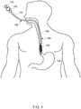
- FIG. 1 illustrates a schematic view of a delivery device 100 (e.g., an endoscopic delivery device) having an endoprosthesis 102 to be placed at a desired location within a lumen of a body.
- the lumen of the body can be any suitable lumen, passage, or passageway in the body.
- an exemplary suitable lumen may be a gastrointestinal tract 104 (e.g., extending from the mouth to the anus) as shown in FIG. 1.
- FIG. 1 illustrates a portion of the gastrointestinal tract 104 that includes, for example, an esophagus 106 and a stomach 108.
- the delivery device 100 can be inserted through a mouth for deploying/delivering the endoprosthesis 102 within the gastrointestinal tract 104. In one or more embodiments, the delivery device 100 can be inserted through a nostril for deploying the endoprosthesis 102.
- gastrointestinal tract 104 of FIG. 1 is shown as an exemplary body lumen in which an endoprosthesis 102 may be delivered, it should be noted that an endoprosthesis 102 may be delivered in other body lumens, without limitation.
- the delivery device 100 includes a plurality of elongate tubes.
- the delivery device includes, for example, three nested (e.g., concentric) tubes, such as an inner tube 110, a middle tube 120, and an outer tube 130.
- inner tube 110, middle tube 120, outer tube 130, and other aspects of delivery device 100 are further described herein.
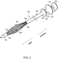
- FIG. 2 illustrates an enlarged perspective view of delivery device 100 (e.g., of FIG. 1 ) having elongate nested (e.g., concentric) tubes including inner tube 110, middle tube 120, and outer tube 130.
- the inner tube 110 may include an inner tube proximal end region 112 and an inner tube distal end region 114 that may include a first retaining mechanism 160 (see FIG. 3A ).
- the middle tube 120 may include a middle tube proximal end region 122 and a middle tube distal end region 124.
- Middle tube 120 may define a middle tube lumen (e.g., extending from the middle tube proximal end region 122 to the middle tube distal end region 124).
- the inner tube 110 may be disposed within the middle tube lumen.
- the inner tube distal end region 114 may be distal of the middle tube distal end region 124.
- the inner tube 110 may be structured and arranged to displace (e.g., translate, slide, move, etc.) proximally and distally relative to (e.g., within, etc.) the middle tube 120.
- the outer tube 130 includes an outer tube proximal end region 132 and an outer tube distal end region 134.
- the outer tube 130 defines an outer tube lumen (e.g., extending from the outer tube proximal end region 132 to the outer tube distal end region 134).
- the middle tube 120 is disposed within the outer tube lumen.
- the outer tube 130 is concentric about the middle tube 120 and/or the middle tube 120 is concentric about the inner tube 110. That is, the inner tube 110 may have the same centerline (e.g., longitudinal axis) as the middle tube 120 and/or outer tube 130, and vice versa. As shown in FIG. 3A , the distal end region 124 of the middle tube 120 is distal of the distal end region 134 of the outer tube 130.
- the outer tube 130 may be structured and arranged to displace proximally and distally relative to (e.g., over, etc.) the middle tube 120.
- Endoscopic delivery device 100 may be used to deliver endoprosthesis 102, as shown in FIG. 2 .
- Each of the inner tube 110, middle tube 120, and outer tube 130 may include (e.g., be made of, be formed from, etc.) a flexible biocompatible plastic material and may be manufactured using any of a wide variety of suitable manufacturing methods including, but not limited to, extrusion.
- the delivery device 100 may further include a first handle 142 attached to (e.g., operatively engaged to, extending from, incorporated with, adhered to, bonded to, friction fitted to, etc.) the proximal end region 112 of the inner tube 110.
- the delivery device 100 may include a second handle 144 and a third handle 146 attached to the middle tube proximal end region 122 and the outer tube proximal end region 132, respectively.
- the second handle 144 maybe distal of the first handle 142 and the third handle 146 can be distal of the second handle 144.
- first distance e.g., in the longitudinal direction parallel to the longitudinal axis of the inner tube 110
- second handle 144 there may be a first distance (e.g., in the longitudinal direction parallel to the longitudinal axis of the inner tube 110) between the first handle 142 and the second handle 144, which may be in a range of about 0 centimeters to about 2 centimeters (e.g., about 1 to about 2 centimeters).
- the present disclosure also contemplates a first distance greater than 2 centimeters.
- second distance between the second handle 144 and the third handle 146, which may be in a range of about 0 centimeters to 2 centimeters (e.g., about 1 to about 2 centimeters).
- first handle 142, second handle 144, and third handle 146 may be made of a rigid material that may include, but is not limited to, one or more plastics, one or more metals, or a combination of these.
- first handle 142, second handle 144, and third handle 146 may be integrally molded or extruded with the inner tube proximal end region 112, middle tube proximal end region 122, and the outer tube proximal end region 132, respectively.
- an endoprosthesis 102 maybe deployed about (e.g., concentric about) and on the middle tube 120 in preparation of and/or during delivery/deployment of the endoprosthesis 102. That is, endoprosthesis 102 may define an endoprosthesis lumen extending longitudinally from an endoprosthesis proximal end 154 to an endoprosthesis distal end 152, wherein at least a portion of middle tube 120 is disposed within the endoprosthesis lumen.
- the endoprosthesis 102 may include an endoprosthesis proximal end 154 and an endoprosthesis distal end 152, none, one, or both of which may be constrained on (e.g., biased against, attached to, etc.) the middle tube 120.
- the middle tube 120 may be constrained on both of the endoprosthesis proximal end 154 and the endoprosthesis distal end 152.
- the inner tube distal end region 114 can include a first retaining mechanism 160 adapted to constrain the endoprosthesis distal end 152 on the middle tube 120
- the outer tube distal end region 134 can include a second retaining mechanism 170 adapted to constrain the endoprosthesis proximal end 154 on the middle tube 120.
- the first retaining mechanism 160 and second retaining mechanism 170 are explained later in greater detail herein, for example, in conjunction with FIG. 3A .
- the endoprosthesis 102 can further include an unconstrained medial region 156 between the endoprosthesis proximal end 154 and the endoprosthesis distal end 152.
- the unconstrained medial region 156 may extend farther from the middle tube 120 (e.g., in a radial direction) than the constrained endoprosthesis proximal end 154 and/or the endoprosthesis distal end 152.
- an endoprosthesis delivered by the endoprosthesis delivery system 100 of the present disclosure may have any of a wide variety of endoprosthesis architectures or designs without limitation.
- the endoprosthesis 102 may include, for example, a portion having a mesh construction formed from at least one wire made from a metal, alloy, plastic, composite, or any other suitable material such as Nitinol.
- the wire may be knitted, woven, or braided into a plurality of overlapping loops to form a wire mesh portion.
- the endoprosthesis may also be manufactured from a laser cut nitinol tube.
- one or both of the endoprosthesis proximal end 154 and the endoprosthesis distal end 152 may be flared (i.e., the diameter of one or both terminal ends, when unconstrained, may be greater than the diameter of the unconstrained medial portion).
- the endoprosthesis 102 may optionally include a membrane extending around at least a portion between the endoprosthesis proximal end 154 and endoprosthesis distal end 152.
- the membrane can be made from any of a wide variety of suitable materials such as expanded polytetrafluoroethylene (ePTFE), latex, silicone, etc.
- the endoprosthesis 102 may include a cover or liner on the inside and/or outside of the endoprosthesis to facilitate sliding the endoprosthesis through a body lumen during delivery.
- the cover or liner may be formed from silicone or urethane for example or ePTFE.
- Such a cover or liner may include a lubricious outer surface to facilitate endoprosthesis delivery.
- the endoprosthesis 102 can be a prosthesis having a length of greater than about 12 centimeters (e.g., greater than 24 centimeters, greater than 30 centimeters, greater than 45 centimeters, in a range of from about 30 centimeters to about 60 centimeters, etc.).
- the endoprosthesis 102 may be a self-expanding prosthesis adapted to radially expand (e.g., extend, etc.) upon removal of a force from one or both of the constrained endoprosthesis proximal end 154 and endoprosthesis distal end 152.
- the endoprosthesis 102 can be configured to exert a low radial force.
- the low radial force may facilitate mitigating undesirable physiological responses, such as lumen wall inflammation and thrombosis formation, and permitting the endoprosthesis 102 to move flexibly in response to external forces such as due to changes in the dimensions of the body lumen or due to posture changes.
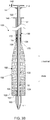
- FIG. 3A illustrates a cross-sectional view of the delivery device 100 with the endoprosthesis distal end 152 and endoprosthesis proximal end 154 of the endoprosthesis 102 held in place (e.g., secured) on the middle tube 120 by the second retaining mechanism 170 and the first retaining mechanism 160, respectively.
- the first retaining mechanism 160 can be a sleeve provided on the inner tube distal end region 114.
- the first retaining mechanism 160 may be a substantially hollow frusto-conical structure that extends proximally from the inner tube distal end region 114 (e.g., from the inner tube terminal distal end).
- the first retaining mechanism 160 may be a separate hollow sleeve component coupled to the inner tube distal end region 114. As shown in Fig. 3A , the first retaining mechanism 160 may define a cavity within which the endoprosthesis distal end 152 may be received. In at least one embodiment, the first retaining mechanism extends in a longitudinal direction proximally over the endoprosthesis distal end 152. In some embodiments, the first retaining mechanism 160 can extend approximately 1 to 2 centimeters over the endoprosthesis distal end 152. That is, the prosthesis distal end 152 may be disposed up to about 2 centimeters into a cavity defined by the first retaining mechanism 160.
- first retaining mechanisms having a cavity that extends longer than 2 centimeters in the longitudinal direction and may be configured and arranged to overlap the endoprosthesis distal end 152 by more than 2 centimeters or, alternatively, about 2 centimeters or less.
- the longitudinal length of the overlap of the first retaining mechanism 160 over the endoprosthesis distal end 152 may be less than the distance that the first handle may move relative to (e.g., toward) the second handle.
- the extent of overlap of the first retaining mechanism 160 over the endoprosthesis distal end 152 may be less than or equal to about 2 centimeters.
- the extent of overlap of the first retaining mechanism 160 over the endoprosthesis distal end 152 is reduced until the first retaining mechanism 160 does not overlap the endoprosthesis distal end 152 (e.g., Fig. 3B ), thereby releasing the endoprosthesis distal end 152 from the first retaining mechanism 160 and allowing the endoprosthesis distal end 152 to radially expand.
- the delivery device 100 includes a distal stopper 162 and a distal endoprosthesis holder 164 on the middle tube distal end region 124.
- the distal stopper 162 and distal endoprosthesis holder 164 along with the sleeve of the first retaining mechanism 160 may be adapted to hold the endoprosthesis proximal end 154 of the endoprosthesis 102 in place, i.e., about the middle tube distal end region 124.
- the distal stopper 162 may be a raised portion (e.g., an annular ridge) configured at an extreme end (e.g., terminal end) of the middle tube distal end region 124.
- the distal stopper 162 may be an integral portion of the middle tube distal end region 124. In at least one embodiment, the distal stopper 162 may be a separate component attached to the middle tube 120 and may take the form of a ring, coupled to the middle tube distal end region 124. The distal stopper 162 may be configured to restrict or constrain axial movement of the endoprosthesis distal end 152 of the endoprosthesis 102 in the distal direction when the endoprosthesis 102 is placed (e.g., concentrically placed) about the middle tube 120.
- the distal endoprosthesis holder 164 is configured proximal of, but near, the distal stopper 162, on the middle tube distal end region 124.
- the distal endoprosthesis holder 164 may be defined as a raised portion.
- the distal endoprosthesis holder 164 can be an integral portion of, or a separate component coupled to, the middle tube distal end region 124.
- the distal stopper 162 may extend radially from the middle tube 120 a greater distance than the distal endoprosthesis holder 164 extends radially from the middle tube 120.
- a difference between the thicknesses (e.g., radial dimension) of the distal stopper 162 and the distal endoprosthesis holder 164 may be less than or equal to a thickness of the endoprosthesis distal end 152 of the endoprosthesis 102. This may allow accommodation of the endoprosthesis distal end 152 of the endoprosthesis 102 between the sleeve of the first retaining mechanism 160 and the distal endoprosthesis holder 164 for securing the endoprosthesis distal end 152 in place on the middle tube 120.
- securing an endoprosthesis (or a portion thereof) to a tube is meant to include securing an endoprosthesis (or a portion thereof) to an endoprosthesis holder (e.g., distal endoprosthesis holder 164, proximal endoprosthesis holder 174, etc.) engaged with or incorporated into the tube (e.g., middle tube 120, etc.).
- an endoprosthesis holder e.g., distal endoprosthesis holder 164, proximal endoprosthesis holder 174, etc.
- the second retaining mechanism 170 may be adapted to hold the endoprosthesis proximal end 154 in place on the middle tube 120.
- the second retaining mechanism may include and/or take the form of a sleeve.
- the second retaining mechanism 170 may be defined by the distal end region 134 of the outer tube 130. Specifically, the distal end region 134 of the outer tube 130 defines a sleeve that may act as the second retaining mechanism, as shown in FIG. 3A .
- the second retaining mechanism 170 may include a separate hollow sleeve-type structure, such as a cylindrical or a conical sleeve, which may be coupled to or integral with the distal end region 134 of the outer tube 130.
- the second retaining mechanism 170 may be configured to extend distally over the endoprosthesis proximal end 154 for holding the endoprosthesis proximal end 154 in place.
- the second retaining mechanism 170 may extend in a longitudinal direction approximately 0 to 2 centimeters over the endoprosthesis proximal end 154.
- the prosthesis proximal end 154 may be disposed up to about 2 centimeters into a cavity defined by the second retaining mechanism 170.
- the present disclosure also contemplates second retaining mechanisms having a cavity that extends longer than 2 centimeters in the longitudinal direction and may be configured and arranged to overlap the endoprosthesis proximal end 154 by more than 2 centimeters or, alternatively, about 2 centimeters or less.
- the longitudinal length of the overlap of the second retaining mechanism 170 over the endoprosthesis proximal end 154 may be less than the distance that the third handle 146 may move relative to (e.g., toward) the second handle 144.
- the extent of overlap of the second retaining mechanism 170 over the endoprosthesis proximal end 154 may be less than or equal to about 2 centimeters.
- the extent of overlap of the second retaining mechanism 170 over the endoprosthesis proximal end 154 is reduced until the second retaining mechanism 170 does not overlap the endoprosthesis proximal end 154 (e.g., Fig. 3C ), thereby releasing the endoprosthesis proximal end 154 from the second retaining mechanism 170 and allowing the endoprosthesis proximal end 154 to radially expand.
- a first retaining mechanism may be structured and arranged in any manner such that the endoprosthesis distal end is secured.
- a first retaining mechanism may utilize a crochet suture rather than the sleeve shown in FIGs. 3A-3C to retain the endoprosthesis distal end 152.
- second retaining mechanism 170 may utilized a crochet suture to secure the endoprosthesis proximal end 154 rather than overlapping the endoprosthesis proximal end 154 with a portion of outer tube 130.
- the delivery device 100 further includes a proximal stopper 172 and preferably a proximal endoprosthesis holder 174 on the middle tube 120 for securing the endoprosthesis proximal end 154 in place (e.g., within the distal end region 134 of the outer tube 130).
- the proximal stopper 172 may be a raised portion on the middle tube distal end region 124 and may be located proximal of the distal stopper 162.
- the proximal stopper 172 may be adapted to restrict axial movement (e.g., in the proximal direction) of the endoprosthesis proximal end 154 of the endoprosthesis 102 away from the distal end region 134 when the endoprosthesis 102 is concentrically placed about the middle tube 120.
- the proximal endoprosthesis holder 174 may be defined as a raised portion on the middle tube distal end region 124 and may be located proximal of the distal endoprosthesis holder 164.
- the proximal stopper 172 may extend radially from the middle tube 120 a greater distance than the proximal endoprosthesis holder 174 extends radially from the middle tube 120.
- a difference between the thicknesses (e.g., radial dimension) of the proximal stopper 172 and the proximal endoprosthesis holder 174 may be less than or equal to a thickness of the endoprosthesis proximal end 154 of the endoprosthesis 102. This may allow accommodation of the endoprosthesis proximal end 154 of the endoprosthesis 102 between the distal end region 134 of the outer tube 130 and the proximal endoprosthesis holder 174 for securing the endoprosthesis proximal end 154 in place on the middle tube 120.
- the endoprosthesis 102 when the endoprosthesis 102 is placed at (e.g., delivered to) a desired location in a body lumen, for example, at a desired location in the gastrointestinal tract 104 (as shown in FIG. 1 ), the endoprosthesis 102 may be deployed at the desired location by releasing or freeing the endoprosthesis proximal end 154 and endoprosthesis proximal end 154.
- FIG. 3B illustrates a cross-sectional view of the delivery device 100 with a freed endoprosthesis distal end 152.
- FIG. 3C illustrates a cross-sectional view of the delivery device 100 with a freed endoprosthesis distal end 152 and endoprosthesis proximal end 154.
- the endoprosthesis distal end 152 of the endoprosthesis 102 can be unconstrained/freed/released by maneuvering the inner tube 110 and/or first handle 142.
- the first handle 142 may be moved forward (shown with arrow A) with respect to the second handle 144 (e.g., keeping the second handle 144 stationary) for proximally displacing the inner tube 110 within the middle tube 120.
- a short stroke of about 1 to 2 cm e.g., the forward (e.g., distal) movement of the first handle 142 with respect to the second handle 144 may be performed.
- the sleeve of the first retaining mechanism 160 can move in a distally axial direction (away from the endoprosthesis distal end 152) and thereby release the endoprosthesis distal end 152 from the distal endoprosthesis holder 164.
- the endoprosthesis distal end 152 may expand due to, for example, a self-expanding nature of the endoprosthesis 102.
- the unconstrained endoprosthesis distal end 152 may expand to have a diameter that is greater than the constrained diameter and may be less than, equal to, or greater than the diameter of the unconstrained medial region 156 of the endoprosthesis 102.
- the endoprosthesis proximal end 154 of the endoprosthesis 102 may thereafter be unconstrained/freed by maneuvering the outer tube 130 and/or third handle 146.
- the third handle 146 may be moved backward (shown with arrow B) (e.g., in a proximal direction) with respect to the second handle 144 (e.g., keeping the second handle 144 stationary) for proximally displacing the outer tube 130 along the middle tube 120.
- a short stroke of about 1 to 2 cm e.g., a backward (proximal) movement of the third handle 146 with respect to the second handle 144 may be performed.
- the outer tube distal end region 134 can move in a proximally axial direction (away from the endoprosthesis proximal end 154) and thereby release the endoprosthesis proximal end 154 from the proximal endoprosthesis holder 174.
- the endoprosthesis proximal end 154 may expand due to, for example, a self-expanding nature of the endoprosthesis 102.
- the unconstrained endoprosthesis proximal end 154 may expand to have a diameter that is greater than the constrained diameter and may be less than, equal to, or greater than the diameter of the unconstrained medial region 156 of the endoprosthesis 102.
- FIGs. 3B and 3C depict first releasing the endoprosthesis distal end 152 and subsequently releasing the endoprosthesis proximal end 154, the present disclosure contemplates releasing the ends in a different order (proximal end, then distal end) or simultaneously.
- the endoprosthesis 102 may expand and may be secured to the desired location in the gastrointestinal tract 104 (or any other bodily lumen the device is intended for delivery in) due to the radial force exerted by the endoprosthesis 102 on the desired location (e.g., the body lumen wall). Thereafter, the inner tube 110, middle tube 120, and outer tube 130 may be removed from the gastrointestinal tract 104 (or other body lumen), which may complete the deployment of the endoprosthesis 102 at the desired location in the gastrointestinal tract 104.
- the inner tube 110, middle tube 120, and outer tubes 130 may be simply pulled individually or collectively through the gastrointestinal tract 104.
- the deployed and expanded endoprosthesis 102 may allow an unobstructed passage of, for example, the first retaining mechanism and the middle tube distal end region to be withdrawn (e.g., in a proximal direction) through the expanded endoprosthesis.
- the delivery device 100 of the present disclosure may facilitate deploying an endoprosthesis by holding only proximal and distal ends of the endoprosthesis, and by having an unconstrained medial region of the endoprosthesis between the constrained proximal and distal ends.
- a delivery device of the present disclosure may allow an endoprosthesis to be installed therein at the fully deployed endoprosthesis length, which may be useful for increasing accuracy of placement of the endoprosthesis at a desired location.
- the delivery device 100 may be capable of delivering and deploying an endoprosthesis having a length of about 30 centimeters to about 60 centimeters or longer.
- the delivery device 100 may be used to deploy an endoprosthesis for treatment of bariatric leaks, especially after a sleeve gastrectomy (e.g., a surgical weight loss procedure in which a stomach is reduced in size) where an endoprosthesis having a length of about 30 centimeters to about 40 centimeters may be deployed.
- the delivery device 100 may be used to deploy a metabolic endoprosthesis that may be up to about 60 centimeters in length or longer.
- the delivery device 100 may also deploy an endoprosthesis having a low radial force, which may easily pass through a body lumen when the medial region of the endoprosthesis is unconstrained.
- the delivery device 100 may be used to deliver a sticky endoprosthesis in some embodiments, because there may be no membrane on such an endoprosthesis and may require a low delivery force.
- the delivery device 100 may be capable of delivering endoprosthesis with one or more micropatterns (e.g., micropatterned surfaces, micropatterned polymer coatings, etc.).
- a method of deploying an endoprosthesis mounted about a tubular body may include providing a delivery device as described herein.
- an delivery device includes a tube (e.g., a middle tube 120 as in Fig. 3A ) on which an endoprosthesis 102 is mounted, a first retaining mechanism 160 extending longitudinally over a first end (e.g., endoprosthesis distal end 152) of the endoprosthesis 102, and a second retaining mechanism 170 extending longitudinally over a second end (e.g., endoprosthesis proximal end) of the endoprosthesis 102.
- the method also includes longitudinally displacing the first retaining mechanism from the first end of the endoprosthesis and longitudinally displacing the second retaining mechanism from the second end of the endoprosthesis.
- the method includes expanding the first end (e.g., endoprosthesis distal end 152) of the endoprosthesis 102 (e.g., after displacing the first retaining mechanism 160).
- a first retaining mechanism may be longitudinally displaced by moving the first retaining mechanism away from the first end of the endoprosthesis. In another embodiment, the first retaining mechanism may be longitudinally displaced by moving the first end of the endoprosthesis away from the first retaining mechanism. As described herein, the first retaining mechanism 160 may be or may include a sleeve of the inner tube 110 adapted to constrain the endoprosthesis distal end 152 on or about the middle tube 120. In some embodiments, the first retaining mechanism 160 may be longitudinally displaced by moving the first retaining mechanism 160 away from the distal end region 124 of the middle tube 120.
- the first retaining mechanism 160 may be longitudinally displaced by moving the distal end region 124 of the middle tube 120 away from the sleeve 160.
- the constrained endoprosthesis distal end 152 may accordingly be released when the first retaining mechanism 160 is moved away from the endoprosthesis distal end 152, as shown in FIG. 3B .
- a method may include positioning an unconstrained medial region of an endoprosthesis at a desired location within a lumen of a body (e.g., for deployment of the endoprosthesis at that location).
- the endoprosthesis 102 may be positioned at a desired location in the gastrointestinal tract 104 by releasing the endoprosthesis proximal end 154 and the endoprosthesis distal end 152, and the unconstrained medial region 156 of the endoprosthesis 102 can expand and contact (e.g., be secured to, etc.) a desired location in the gastrointestinal tract 104.
- the medial region of the endoprosthesis 102 maybe disposed between the endoprosthesis distal end 152 and the endoprosthesis proximal end 154.
- the medial region may extend from the tube (e.g., a middle tube 120) in a radial direction farther than the one or more constrained endoprosthesis ends.
Description
- This disclosure relates to a delivery device for an endoprosthesis (e.g., an intraluminary prosthesis). Particularly, it relates to a delivery device for placing an endoprosthesis at a desired location within a body lumen (e.g., a gastrointestinal tract of a body).
- An intraluminary prosthesis (e.g., a stent), is a medical device used in, for example, the treatment of body lumens (e.g., diseased body lumens). A stent is generally a longitudinal tubular structure configured to radially expand when deployed at a desired implant site.
- Although endoprosthesis delivery devices are well-known in the art, the assembly of such a delivery device is often complicated. Also, loading an endoprosthesis in such delivery device may be often difficult and time-consuming. For example, an endoprosthesis may be a polymeric or plastic self-expanding stent, which may be difficult to load on a delivery device due to its length. In some cases, elongation of the endoprosthesis may be required while loading in the delivery device. An elongated endoprosthesis may be difficult to accurately deliver at a desired location. For delivery of a relatively long endoprosthesis, a corresponding delivery device may be long or a high delivery force may be required.
-
EP 2 529 701 relates to a deployment system for deploying an expandable cardiac valve prosthesis. The deployment system comprises a first tube being designed to carry an expandable cardiac valve prosthesis; further, a tip, being firmly connected to the first tube at a distal end of the first tube, wherein the tip is designed such, that it detachably accommodates and holds a distal end of a cardiac valve prosthesis; a sheath designed to be disposed over and holding the prosthesis in a compressed state, and a first actuating mechanism being linked to the sheath and being slidable in a proximal direction for stepwise retracting the sheath. - Some endoscopic delivery devices are described by
Heyn et al. (U.S. Pat. No. 5,201,757 ),Wang et al. (U.S. Pat. No. 6,331,186 ),Hanson (U.S. Pat. No. 6,432,130 ),Euteneuer et al. (U.S. Pat. No. 5,562,063 ),Stenzel et al. (U.S. Pat. No. 6,830,575 ), andRabkin et al. (U.S. Pat. No. 7,074,236 ). - Thus, there exists a need for improved endoscopic delivery devices suitable for delivering an endoprosthesis, such as a stent. In particular, there exists a need for improved endoscopic delivery devices suitable for delivering an endoprosthesis having a length of about 30 centimeters or greater.
- Without limiting the scope of the present disclosure, a brief summary of some of the claimed embodiments is provided below. Additional details of the summarized embodiments and/or additional embodiments can be found in the detailed description.
- The present invention is defined by the features of independent claim 1. Further preferred embodiments of the present invention are defined in the dependent claims.
- In at least one example, the present disclosure is directed to a delivery device (e.g., an endoscopic delivery device) including an inner tube having an inner tube proximal end region and an inner tube distal end region, a middle tube having a middle tube distal end region and a middle tube proximal end region and defining a middle tube lumen, and an outer tube having an outer tube proximal end region and an outer tube distal end region and defining an outer tube lumen. The inner tube is disposed within the middle tube lumen and the middle tube is disposed within the outer tube lumen. The inner tube distal end region includes a first retaining mechanism and the outer tube distal end region includes a second retaining mechanism. In at least one embodiment, the inner tube is structured and arranged to displace proximally and distally relative to the middle tube, and the outer tube is structured and arranged to displace proximally and distally relative to the middle tube.
- In at least one example, the present disclosure is directed to a method of deploying an endoprosthesis mounted about a tube including providing an delivery device including a tube on which an endoprosthesis is mounted, a first retaining mechanism extending longitudinally over a first end of the endoprosthesis, and a second retaining mechanism extending longitudinally over a second end of the endoprosthesis. The method further includes longitudinally displacing the first retaining mechanism from the first end of the device; and longitudinally displacing the second retaining mechanism from the second end of the device.
- The present disclosure, including the following detailed description of certain embodiments, can be understood with reference to the following figures:
-
FIG. 1 illustrates a schematic view of a delivery device, in accordance with an exemplary embodiment of the present disclosure, that includes an endoprosthesis to be deployed at a desired location within a lumen of a body. -
FIG. 2 illustrates an enlarged perspective view of the delivery device, in accordance with an exemplary embodiment of the present disclosure, ofFIG. 1 having nested tubes and the endoprosthesis. -
FIG. 3A illustrates a cross-sectional view of the delivery device, in accordance with an exemplary embodiment of the present disclosure, with proximal and distal ends of the endoprosthesis secured while a medial portion of the endoprosthesis is unconstrained. -
FIG. 3B illustrates a cross-sectional view of the delivery device, in accordance with an exemplary embodiment of the present disclosure, with an unconstrained distal end of the endoprosthesis and medial portion of the endoprosthesis. -
FIG. 3C illustrates a cross-sectional view of the delivery device, in accordance with an exemplary embodiment of the present disclosure, with unconstrained distal and proximal ends of the endoprosthesis and medial portion of the endoprosthesis. - While the subject matter of the present disclosure can be embodied in many different forms, specific embodiments of the subject matter of the present disclosure are described in detail herein. This description is an exemplification of the principles of the present disclosure and is not intended to limit the present disclosure to the particular embodiments illustrated.
- For the purposes of this disclosure, like reference numerals (e.g., in the figures) shall refer to like features unless otherwise indicated. For example,
reference numeral 110 inFig. 1 andreference numeral 110 inFig. 2 refer to like features (an inner tube). Moreover,inner tube 110, as depicted in a given figure, may include any of the structures or characteristics depicted in another figure or otherwise described herein. - Various aspects of the present disclosure are depicted in the figures. Elements depicted in one figure may be combined with and/or substituted for elements depicted in any other another figure, as may be desired by one of ordinary skill in the art.
- The terms "proximal" and "distal" described in relation to various devices, apparatuses, and components-as discussed in the text of the present disclosure-are referred with a point of reference. The point of reference, as used in this description, is a perspective of an operator. The operator can be, for example, a surgeon, a physician, a nurse, a doctor, a technician, or the like, who may perform the procedure of delivery and placement of the disclosed system/device into a patient's body, as described in the present disclosure. The term "proximal" refers to an area or portion that is closer or closest to the operator during a placement procedure. The term "distal" refers to an area or portion that is farther or farthest from the operator during a placement procedure.
-
FIG. 1 illustrates a schematic view of a delivery device 100 (e.g., an endoscopic delivery device) having anendoprosthesis 102 to be placed at a desired location within a lumen of a body. The lumen of the body can be any suitable lumen, passage, or passageway in the body. For example, an exemplary suitable lumen may be a gastrointestinal tract 104 (e.g., extending from the mouth to the anus) as shown inFIG. 1. FIG. 1 illustrates a portion of thegastrointestinal tract 104 that includes, for example, anesophagus 106 and astomach 108. In one or more embodiments, thedelivery device 100 can be inserted through a mouth for deploying/delivering theendoprosthesis 102 within thegastrointestinal tract 104. In one or more embodiments, thedelivery device 100 can be inserted through a nostril for deploying theendoprosthesis 102. Althoughgastrointestinal tract 104 ofFIG. 1 is shown as an exemplary body lumen in which anendoprosthesis 102 may be delivered, it should be noted that anendoprosthesis 102 may be delivered in other body lumens, without limitation. - As shown in
FIGs. 1 and2 , thedelivery device 100 includes a plurality of elongate tubes. In at least one embodiment, the delivery device includes, for example, three nested (e.g., concentric) tubes, such as aninner tube 110, amiddle tube 120, and anouter tube 130. Other details ofinner tube 110,middle tube 120,outer tube 130, and other aspects ofdelivery device 100 are further described herein. -
FIG. 2 illustrates an enlarged perspective view of delivery device 100 (e.g., ofFIG. 1 ) having elongate nested (e.g., concentric) tubes includinginner tube 110,middle tube 120, andouter tube 130. InFIG. 2 , theinner tube 110 may include an inner tubeproximal end region 112 and an inner tubedistal end region 114 that may include a first retaining mechanism 160 (seeFIG. 3A ). Themiddle tube 120 may include a middle tubeproximal end region 122 and a middle tubedistal end region 124.Middle tube 120 may define a middle tube lumen (e.g., extending from the middle tubeproximal end region 122 to the middle tube distal end region 124). Theinner tube 110 may be disposed within the middle tube lumen. - The inner tube
distal end region 114 may be distal of the middle tubedistal end region 124. Theinner tube 110 may be structured and arranged to displace (e.g., translate, slide, move, etc.) proximally and distally relative to (e.g., within, etc.) themiddle tube 120. Theouter tube 130 includes an outer tubeproximal end region 132 and an outer tubedistal end region 134. Theouter tube 130 defines an outer tube lumen (e.g., extending from the outer tubeproximal end region 132 to the outer tube distal end region 134). Themiddle tube 120 is disposed within the outer tube lumen. - In at least one embodiment, as shown in
Figs. 3A-3C , theouter tube 130 is concentric about themiddle tube 120 and/or themiddle tube 120 is concentric about theinner tube 110. That is, theinner tube 110 may have the same centerline (e.g., longitudinal axis) as themiddle tube 120 and/orouter tube 130, and vice versa. As shown inFIG. 3A , thedistal end region 124 of themiddle tube 120 is distal of thedistal end region 134 of theouter tube 130. Theouter tube 130 may be structured and arranged to displace proximally and distally relative to (e.g., over, etc.) themiddle tube 120. -
Endoscopic delivery device 100 may be used to deliverendoprosthesis 102, as shown inFIG. 2 . - Each of the
inner tube 110,middle tube 120, andouter tube 130 may include (e.g., be made of, be formed from, etc.) a flexible biocompatible plastic material and may be manufactured using any of a wide variety of suitable manufacturing methods including, but not limited to, extrusion. - In one or more embodiments, the
delivery device 100 may further include afirst handle 142 attached to (e.g., operatively engaged to, extending from, incorporated with, adhered to, bonded to, friction fitted to, etc.) theproximal end region 112 of theinner tube 110. Similarly, thedelivery device 100 may include asecond handle 144 and athird handle 146 attached to the middle tubeproximal end region 122 and the outer tubeproximal end region 132, respectively. In at least one embodiment shown inFig. 3A , thesecond handle 144 maybe distal of thefirst handle 142 and thethird handle 146 can be distal of thesecond handle 144. In some embodiments, there may be a first distance (e.g., in the longitudinal direction parallel to the longitudinal axis of the inner tube 110) between thefirst handle 142 and thesecond handle 144, which may be in a range of about 0 centimeters to about 2 centimeters (e.g., about 1 to about 2 centimeters). The present disclosure also contemplates a first distance greater than 2 centimeters. Similarly, there may be a second distance between thesecond handle 144 and thethird handle 146, which may be in a range of about 0 centimeters to 2 centimeters (e.g., about 1 to about 2 centimeters). The present disclosure also contemplates a second distance up to greater than 2 centimeters (e.g., up to 3 centimeters, up to 5 centimeters, up to 10 centimeters, etc.). Each of thefirst handle 142,second handle 144, andthird handle 146 may be made of a rigid material that may include, but is not limited to, one or more plastics, one or more metals, or a combination of these. In some embodiments, thefirst handle 142,second handle 144, andthird handle 146 may be integrally molded or extruded with the inner tubeproximal end region 112, middle tubeproximal end region 122, and the outer tubeproximal end region 132, respectively. - As shown in, for example,
FIG. 3A , anendoprosthesis 102 maybe deployed about (e.g., concentric about) and on themiddle tube 120 in preparation of and/or during delivery/deployment of theendoprosthesis 102. That is,endoprosthesis 102 may define an endoprosthesis lumen extending longitudinally from an endoprosthesisproximal end 154 to an endoprosthesisdistal end 152, wherein at least a portion ofmiddle tube 120 is disposed within the endoprosthesis lumen. Specifically, theendoprosthesis 102 may include an endoprosthesisproximal end 154 and an endoprosthesisdistal end 152, none, one, or both of which may be constrained on (e.g., biased against, attached to, etc.) themiddle tube 120. For example, inFig. 3A , both of the endoprosthesisproximal end 154 and the endoprosthesisdistal end 152 are constrained on the middle tube. In at least one embodiment, the inner tubedistal end region 114 can include afirst retaining mechanism 160 adapted to constrain the endoprosthesisdistal end 152 on themiddle tube 120, and the outer tubedistal end region 134 can include asecond retaining mechanism 170 adapted to constrain the endoprosthesisproximal end 154 on themiddle tube 120. Thefirst retaining mechanism 160 andsecond retaining mechanism 170 are explained later in greater detail herein, for example, in conjunction withFIG. 3A . Theendoprosthesis 102 can further include an unconstrainedmedial region 156 between the endoprosthesisproximal end 154 and the endoprosthesisdistal end 152. The unconstrainedmedial region 156 may extend farther from the middle tube 120 (e.g., in a radial direction) than the constrained endoprosthesisproximal end 154 and/or the endoprosthesisdistal end 152. - An endoprosthesis delivered by the
endoprosthesis delivery system 100 of the present disclosure may have any of a wide variety of endoprosthesis architectures or designs without limitation. As shown inFig. 3A , theendoprosthesis 102 may include, for example, a portion having a mesh construction formed from at least one wire made from a metal, alloy, plastic, composite, or any other suitable material such as Nitinol. The wire may be knitted, woven, or braided into a plurality of overlapping loops to form a wire mesh portion. The endoprosthesis may also be manufactured from a laser cut nitinol tube. In some embodiments, one or both of the endoprosthesisproximal end 154 and the endoprosthesisdistal end 152 may be flared (i.e., the diameter of one or both terminal ends, when unconstrained, may be greater than the diameter of the unconstrained medial portion). Further, theendoprosthesis 102 may optionally include a membrane extending around at least a portion between the endoprosthesisproximal end 154 and endoprosthesisdistal end 152. The membrane can be made from any of a wide variety of suitable materials such as expanded polytetrafluoroethylene (ePTFE), latex, silicone, etc. In one or more embodiments, theendoprosthesis 102 may include a cover or liner on the inside and/or outside of the endoprosthesis to facilitate sliding the endoprosthesis through a body lumen during delivery. The cover or liner may be formed from silicone or urethane for example or ePTFE. Such a cover or liner may include a lubricious outer surface to facilitate endoprosthesis delivery. - In some embodiments, the
endoprosthesis 102 can be a prosthesis having a length of greater than about 12 centimeters (e.g., greater than 24 centimeters, greater than 30 centimeters, greater than 45 centimeters, in a range of from about 30 centimeters to about 60 centimeters, etc.). In some embodiments, theendoprosthesis 102 may be a self-expanding prosthesis adapted to radially expand (e.g., extend, etc.) upon removal of a force from one or both of the constrained endoprosthesisproximal end 154 and endoprosthesisdistal end 152. Also, in at least one embodiment, theendoprosthesis 102 can be configured to exert a low radial force. The low radial force may facilitate mitigating undesirable physiological responses, such as lumen wall inflammation and thrombosis formation, and permitting theendoprosthesis 102 to move flexibly in response to external forces such as due to changes in the dimensions of the body lumen or due to posture changes. -
FIG. 3A illustrates a cross-sectional view of thedelivery device 100 with the endoprosthesisdistal end 152 and endoprosthesisproximal end 154 of theendoprosthesis 102 held in place (e.g., secured) on themiddle tube 120 by thesecond retaining mechanism 170 and thefirst retaining mechanism 160, respectively. In some embodiments, thefirst retaining mechanism 160 can be a sleeve provided on the inner tubedistal end region 114. For example, thefirst retaining mechanism 160 may be a substantially hollow frusto-conical structure that extends proximally from the inner tube distal end region 114 (e.g., from the inner tube terminal distal end). In one or more embodiments, thefirst retaining mechanism 160 may be a separate hollow sleeve component coupled to the inner tubedistal end region 114. As shown inFig. 3A , thefirst retaining mechanism 160 may define a cavity within which the endoprosthesisdistal end 152 may be received. In at least one embodiment, the first retaining mechanism extends in a longitudinal direction proximally over the endoprosthesisdistal end 152. In some embodiments, thefirst retaining mechanism 160 can extend approximately 1 to 2 centimeters over the endoprosthesisdistal end 152. That is, the prosthesisdistal end 152 may be disposed up to about 2 centimeters into a cavity defined by thefirst retaining mechanism 160. The present disclosure also contemplates first retaining mechanisms having a cavity that extends longer than 2 centimeters in the longitudinal direction and may be configured and arranged to overlap the endoprosthesisdistal end 152 by more than 2 centimeters or, alternatively, about 2 centimeters or less. In one or more embodiments, the longitudinal length of the overlap of thefirst retaining mechanism 160 over the endoprosthesisdistal end 152 may be less than the distance that the first handle may move relative to (e.g., toward) the second handle. For example, if thefirst handle 142 may move up to about 2 centimeters toward thesecond handle 144, then the extent of overlap of thefirst retaining mechanism 160 over the endoprosthesisdistal end 152 may be less than or equal to about 2 centimeters. When thefirst handle 142 is moved closer toward thesecond handle 144, the extent of overlap of thefirst retaining mechanism 160 over the endoprosthesisdistal end 152 is reduced until thefirst retaining mechanism 160 does not overlap the endoprosthesis distal end 152 (e.g.,Fig. 3B ), thereby releasing the endoprosthesisdistal end 152 from thefirst retaining mechanism 160 and allowing the endoprosthesisdistal end 152 to radially expand. - In one or more embodiments, the
delivery device 100 includes adistal stopper 162 and adistal endoprosthesis holder 164 on the middle tubedistal end region 124. Thedistal stopper 162 anddistal endoprosthesis holder 164 along with the sleeve of thefirst retaining mechanism 160 may be adapted to hold the endoprosthesisproximal end 154 of theendoprosthesis 102 in place, i.e., about the middle tubedistal end region 124. Thedistal stopper 162 may be a raised portion (e.g., an annular ridge) configured at an extreme end (e.g., terminal end) of the middle tubedistal end region 124. In at least one embodiment, thedistal stopper 162 may be an integral portion of the middle tubedistal end region 124. In at least one embodiment, thedistal stopper 162 may be a separate component attached to themiddle tube 120 and may take the form of a ring, coupled to the middle tubedistal end region 124. Thedistal stopper 162 may be configured to restrict or constrain axial movement of the endoprosthesisdistal end 152 of theendoprosthesis 102 in the distal direction when theendoprosthesis 102 is placed (e.g., concentrically placed) about themiddle tube 120. - In one or more embodiments, the
distal endoprosthesis holder 164 is configured proximal of, but near, thedistal stopper 162, on the middle tubedistal end region 124. Thedistal endoprosthesis holder 164 may be defined as a raised portion. In various embodiments, thedistal endoprosthesis holder 164 can be an integral portion of, or a separate component coupled to, the middle tubedistal end region 124. In some embodiments, thedistal stopper 162 may extend radially from the middle tube 120 a greater distance than thedistal endoprosthesis holder 164 extends radially from themiddle tube 120. Further, a difference between the thicknesses (e.g., radial dimension) of thedistal stopper 162 and thedistal endoprosthesis holder 164 may be less than or equal to a thickness of the endoprosthesisdistal end 152 of theendoprosthesis 102. This may allow accommodation of the endoprosthesisdistal end 152 of theendoprosthesis 102 between the sleeve of thefirst retaining mechanism 160 and thedistal endoprosthesis holder 164 for securing the endoprosthesisdistal end 152 in place on themiddle tube 120. In one or more embodiments securing an endoprosthesis (or a portion thereof) to a tube (e.g., amiddle tube 120, etc.) is meant to include securing an endoprosthesis (or a portion thereof) to an endoprosthesis holder (e.g.,distal endoprosthesis holder 164,proximal endoprosthesis holder 174, etc.) engaged with or incorporated into the tube (e.g.,middle tube 120, etc.). - As mentioned above, the
second retaining mechanism 170 may be adapted to hold the endoprosthesisproximal end 154 in place on themiddle tube 120. In some embodiments, the second retaining mechanism may include and/or take the form of a sleeve. In the one or more embodiments ofFIGs. 3A-3C , thesecond retaining mechanism 170 may be defined by thedistal end region 134 of theouter tube 130. Specifically, thedistal end region 134 of theouter tube 130 defines a sleeve that may act as the second retaining mechanism, as shown inFIG. 3A . In one or more embodiments, thesecond retaining mechanism 170 may include a separate hollow sleeve-type structure, such as a cylindrical or a conical sleeve, which may be coupled to or integral with thedistal end region 134 of theouter tube 130. Thesecond retaining mechanism 170 may be configured to extend distally over the endoprosthesisproximal end 154 for holding the endoprosthesisproximal end 154 in place. In some embodiments, thesecond retaining mechanism 170 may extend in a longitudinal direction approximately 0 to 2 centimeters over the endoprosthesisproximal end 154. That is, the prosthesisproximal end 154 may be disposed up to about 2 centimeters into a cavity defined by thesecond retaining mechanism 170. The present disclosure also contemplates second retaining mechanisms having a cavity that extends longer than 2 centimeters in the longitudinal direction and may be configured and arranged to overlap the endoprosthesisproximal end 154 by more than 2 centimeters or, alternatively, about 2 centimeters or less. In one or more embodiments, the longitudinal length of the overlap of thesecond retaining mechanism 170 over the endoprosthesisproximal end 154 may be less than the distance that thethird handle 146 may move relative to (e.g., toward) thesecond handle 144. For example, if thethird handle 146 may move up to about 2 centimeters toward thesecond handle 144, then the extent of overlap of thesecond retaining mechanism 170 over the endoprosthesisproximal end 154 may be less than or equal to about 2 centimeters. When thethird handle 146 is moved closer toward thesecond handle 144, the extent of overlap of thesecond retaining mechanism 170 over the endoprosthesisproximal end 154 is reduced until thesecond retaining mechanism 170 does not overlap the endoprosthesis proximal end 154 (e.g.,Fig. 3C ), thereby releasing the endoprosthesisproximal end 154 from thesecond retaining mechanism 170 and allowing the endoprosthesisproximal end 154 to radially expand. - In one or more embodiments, a first retaining mechanism may be structured and arranged in any manner such that the endoprosthesis distal end is secured. For example, a first retaining mechanism may utilize a crochet suture rather than the sleeve shown in
FIGs. 3A-3C to retain the endoprosthesisdistal end 152. Similarly,second retaining mechanism 170 may utilized a crochet suture to secure the endoprosthesisproximal end 154 rather than overlapping the endoprosthesisproximal end 154 with a portion ofouter tube 130. - In one or more embodiments, the
delivery device 100 further includes aproximal stopper 172 and preferably aproximal endoprosthesis holder 174 on themiddle tube 120 for securing the endoprosthesisproximal end 154 in place (e.g., within thedistal end region 134 of the outer tube 130). In one or more embodiments, theproximal stopper 172 may be a raised portion on the middle tubedistal end region 124 and may be located proximal of thedistal stopper 162. Theproximal stopper 172 may be adapted to restrict axial movement (e.g., in the proximal direction) of the endoprosthesisproximal end 154 of theendoprosthesis 102 away from thedistal end region 134 when theendoprosthesis 102 is concentrically placed about themiddle tube 120. Theproximal endoprosthesis holder 174 may be defined as a raised portion on the middle tubedistal end region 124 and may be located proximal of thedistal endoprosthesis holder 164. In some embodiments, theproximal stopper 172 may extend radially from the middle tube 120 a greater distance than theproximal endoprosthesis holder 174 extends radially from themiddle tube 120. Further, a difference between the thicknesses (e.g., radial dimension) of theproximal stopper 172 and theproximal endoprosthesis holder 174 may be less than or equal to a thickness of the endoprosthesisproximal end 154 of theendoprosthesis 102. This may allow accommodation of the endoprosthesisproximal end 154 of theendoprosthesis 102 between thedistal end region 134 of theouter tube 130 and theproximal endoprosthesis holder 174 for securing the endoprosthesisproximal end 154 in place on themiddle tube 120. - Specifically, during operation, when the
endoprosthesis 102 is placed at (e.g., delivered to) a desired location in a body lumen, for example, at a desired location in the gastrointestinal tract 104 (as shown inFIG. 1 ), theendoprosthesis 102 may be deployed at the desired location by releasing or freeing the endoprosthesisproximal end 154 and endoprosthesisproximal end 154.FIG. 3B illustrates a cross-sectional view of thedelivery device 100 with a freed endoprosthesisdistal end 152.FIG. 3C illustrates a cross-sectional view of thedelivery device 100 with a freed endoprosthesisdistal end 152 and endoprosthesisproximal end 154. As shown inFIG. 3B , the endoprosthesisdistal end 152 of theendoprosthesis 102 can be unconstrained/freed/released by maneuvering theinner tube 110 and/orfirst handle 142. Specifically, thefirst handle 142 may be moved forward (shown with arrow A) with respect to the second handle 144 (e.g., keeping thesecond handle 144 stationary) for proximally displacing theinner tube 110 within themiddle tube 120. For example, a short stroke of about 1 to 2 cm, e.g., the forward (e.g., distal) movement of thefirst handle 142 with respect to thesecond handle 144 may be performed. This can cause the sleeve of thefirst retaining mechanism 160 to move in a distally axial direction (away from the endoprosthesis distal end 152) and thereby release the endoprosthesisdistal end 152 from thedistal endoprosthesis holder 164. Once the endoprosthesisdistal end 152 is released, the endoprosthesisdistal end 152 may expand due to, for example, a self-expanding nature of theendoprosthesis 102. In one or more embodiments, the unconstrained endoprosthesisdistal end 152 may expand to have a diameter that is greater than the constrained diameter and may be less than, equal to, or greater than the diameter of the unconstrainedmedial region 156 of theendoprosthesis 102. - In one or more embodiments, as shown in
FIG. 3C , the endoprosthesisproximal end 154 of theendoprosthesis 102 may thereafter be unconstrained/freed by maneuvering theouter tube 130 and/orthird handle 146. Specifically, thethird handle 146 may be moved backward (shown with arrow B) (e.g., in a proximal direction) with respect to the second handle 144 (e.g., keeping thesecond handle 144 stationary) for proximally displacing theouter tube 130 along themiddle tube 120. For example, a short stroke of about 1 to 2 cm, e.g., a backward (proximal) movement of thethird handle 146 with respect to thesecond handle 144 may be performed. This can cause the outer tubedistal end region 134 to move in a proximally axial direction (away from the endoprosthesis proximal end 154) and thereby release the endoprosthesisproximal end 154 from theproximal endoprosthesis holder 174. Once the endoprosthesisproximal end 154 is released, the endoprosthesisproximal end 154 may expand due to, for example, a self-expanding nature of theendoprosthesis 102. In one or more embodiments, the unconstrained endoprosthesisproximal end 154 may expand to have a diameter that is greater than the constrained diameter and may be less than, equal to, or greater than the diameter of the unconstrainedmedial region 156 of theendoprosthesis 102. - Although
FIGs. 3B and3C depict first releasing the endoprosthesisdistal end 152 and subsequently releasing the endoprosthesisproximal end 154, the present disclosure contemplates releasing the ends in a different order (proximal end, then distal end) or simultaneously. - Once both of the endoprosthesis
proximal end 154 and endoprosthesisdistal end 152 are released, theendoprosthesis 102 may expand and may be secured to the desired location in the gastrointestinal tract 104 (or any other bodily lumen the device is intended for delivery in) due to the radial force exerted by theendoprosthesis 102 on the desired location (e.g., the body lumen wall). Thereafter, theinner tube 110,middle tube 120, andouter tube 130 may be removed from the gastrointestinal tract 104 (or other body lumen), which may complete the deployment of theendoprosthesis 102 at the desired location in thegastrointestinal tract 104. For example, theinner tube 110,middle tube 120, andouter tubes 130 may be simply pulled individually or collectively through thegastrointestinal tract 104. In one or more embodiments, the deployed and expandedendoprosthesis 102 may allow an unobstructed passage of, for example, the first retaining mechanism and the middle tube distal end region to be withdrawn (e.g., in a proximal direction) through the expanded endoprosthesis. - The
delivery device 100 of the present disclosure may facilitate deploying an endoprosthesis by holding only proximal and distal ends of the endoprosthesis, and by having an unconstrained medial region of the endoprosthesis between the constrained proximal and distal ends. A delivery device of the present disclosure may allow an endoprosthesis to be installed therein at the fully deployed endoprosthesis length, which may be useful for increasing accuracy of placement of the endoprosthesis at a desired location. Thedelivery device 100 may be capable of delivering and deploying an endoprosthesis having a length of about 30 centimeters to about 60 centimeters or longer. In one or more embodiments, thedelivery device 100 may be used to deploy an endoprosthesis for treatment of bariatric leaks, especially after a sleeve gastrectomy (e.g., a surgical weight loss procedure in which a stomach is reduced in size) where an endoprosthesis having a length of about 30 centimeters to about 40 centimeters may be deployed. In one or more embodiments, thedelivery device 100 may be used to deploy a metabolic endoprosthesis that may be up to about 60 centimeters in length or longer. In at least one embodiment, thedelivery device 100 may also deploy an endoprosthesis having a low radial force, which may easily pass through a body lumen when the medial region of the endoprosthesis is unconstrained. Thedelivery device 100 may be used to deliver a sticky endoprosthesis in some embodiments, because there may be no membrane on such an endoprosthesis and may require a low delivery force. Thedelivery device 100 may be capable of delivering endoprosthesis with one or more micropatterns (e.g., micropatterned surfaces, micropatterned polymer coatings, etc.). - In one or more aspects of the present disclosure, a method of deploying an endoprosthesis mounted about a tubular body is provided. For example, in one or more embodiments, a method may include providing a delivery device as described herein. In at least one embodiment, an delivery device includes a tube (e.g., a
middle tube 120 as inFig. 3A ) on which anendoprosthesis 102 is mounted, afirst retaining mechanism 160 extending longitudinally over a first end (e.g., endoprosthesis distal end 152) of theendoprosthesis 102, and asecond retaining mechanism 170 extending longitudinally over a second end (e.g., endoprosthesis proximal end) of theendoprosthesis 102. The method also includes longitudinally displacing the first retaining mechanism from the first end of the endoprosthesis and longitudinally displacing the second retaining mechanism from the second end of the endoprosthesis. In one or more embodiments, the method includes expanding the first end (e.g., endoprosthesis distal end 152) of the endoprosthesis 102 (e.g., after displacing the first retaining mechanism 160). - In one or more embodiments, a first retaining mechanism may be longitudinally displaced by moving the first retaining mechanism away from the first end of the endoprosthesis. In another embodiment, the first retaining mechanism may be longitudinally displaced by moving the first end of the endoprosthesis away from the first retaining mechanism. As described herein, the
first retaining mechanism 160 may be or may include a sleeve of theinner tube 110 adapted to constrain the endoprosthesisdistal end 152 on or about themiddle tube 120. In some embodiments, thefirst retaining mechanism 160 may be longitudinally displaced by moving thefirst retaining mechanism 160 away from thedistal end region 124 of themiddle tube 120. In some embodiments, thefirst retaining mechanism 160 may be longitudinally displaced by moving thedistal end region 124 of themiddle tube 120 away from thesleeve 160. The constrained endoprosthesisdistal end 152 may accordingly be released when thefirst retaining mechanism 160 is moved away from the endoprosthesisdistal end 152, as shown inFIG. 3B . - In one or more embodiments of the present disclosure, a method may include positioning an unconstrained medial region of an endoprosthesis at a desired location within a lumen of a body (e.g., for deployment of the endoprosthesis at that location). For example, the
endoprosthesis 102 may be positioned at a desired location in thegastrointestinal tract 104 by releasing the endoprosthesisproximal end 154 and the endoprosthesisdistal end 152, and the unconstrainedmedial region 156 of theendoprosthesis 102 can expand and contact (e.g., be secured to, etc.) a desired location in thegastrointestinal tract 104. The medial region of theendoprosthesis 102 maybe disposed between the endoprosthesisdistal end 152 and the endoprosthesisproximal end 154. When the medial region is unconstrained, it may extend from the tube (e.g., a middle tube 120) in a radial direction farther than the one or more constrained endoprosthesis ends.
Claims (12)
- A delivery device for an endoprosthesis comprising:an inner tube (110) having an inner tube proximal end region (112) and an inner tube distal end region (114), the inner tube distal end region (114) comprising a first retaining mechanism (160);a middle tube (120) having a middle tube distal end region (124) and a middle tube proximal end region (122) and defining a middle tube lumen, the inner tube (110) disposed within the middle tube lumen, the middle tube distal end region (124) comprising a distal stopper (162), the middle tube (120) further comprising a proximal stopper (172) spaced apart from and located proximal of the distal stopper (162); andan outer tube (130) having an outer tube proximal end region (132) and an outer tube distal end region (134) and defining an outer tube lumen, the middle tube (120) disposed within the outer tube lumen, the outer tube distal end region (134) comprising a second retaining mechanism (170);wherein the inner tube (110) is structured and arranged to displace proximally and distally relative to the middle tube (120), andwherein the outer tube (130) is structured and arranged to displace proximally and distally relative to the middle tube (120).
- The delivery device of claim 1 further comprising a distal endoprosthesis holder (164) on the middle tube (120) in the middle tube distal end region (124) and a proximal endoprosthesis holder (174) on the middle tube (120), the proximal endoprosthesis holder (174) located proximal of the distal endoprosthesis holder (164).
- The delivery device of claim 1 wherein the distal end region (114) of the inner tube (110) is distal of the distal end region (124) of the middle tube (120), and wherein the distal end region (124) of the middle tube (120) is distal of the distal end region (134) of the outer tube (130).
- The delivery device of claim 1 further comprising a first handle (142) attached to the proximal end region (112) of the inner tube (110); a second handle (144) attached to the proximal end region (122) of the middle tube (120), the second handle (144) distal of the first handle (142); and a third handle (146) attached to the proximal end region (132) of the outer tube (130), the third handle (146) distal of the second handle (144).
- The delivery device of claim 4 wherein a first distance between the first handle (142) and the second handle (144) is in a range of about 0 centimeters to about 2 centimeters.
- The delivery device of claim 4 wherein a second distance between the second handle (144) and the third handle (146) is in a range of about 0 centimeters to about 2 centimeters.
- The delivery device of claim 1 further comprising an endoprosthesis (102) that comprises an endoprosthesis distal end (152) constrained on the middle tube (120) by the first retaining mechanism (160) and an endoprosthesis proximal end (154) constrained on the middle tube (120) by the second retaining mechanism (170), wherein the endoprosthesis (102) defines an endoprosthesis lumen, the middle tube (120) disposed within the endoprosthesis lumen.
- The delivery device of claim 7 wherein the first retaining mechanism (160) comprises a first sleeve extending proximally over the endoprosthesis distal end (152).
- The delivery device of claim 7 wherein the second retaining mechanism (170) comprises a second sleeve extending distally over the endoprosthesis proximal end (154).
- The delivery device of claim 7 wherein the endoprosthesis (102) further comprises an unconstrained medial region (156) extending farther from the middle tube (120) than the constrained endoprosthesis distal end (152) and the constrained endoprosthesis proximal end (154).
- The delivery device of claim 7 wherein the endoprosthesis (102) has an endoprosthesis length in a range of about 30 centimeters to about 60 centimeters.
- The delivery device of claim 7 wherein the endoprosthesis (102) has a low radial force.
Applications Claiming Priority (2)
| Application Number | Priority Date | Filing Date | Title |
|---|---|---|---|
| US201361798794P | 2013-03-15 | 2013-03-15 | |
| PCT/US2014/027871 WO2014143767A1 (en) | 2013-03-15 | 2014-03-14 | Delivery device for partially unconstrained endoprosthesis |
Publications (2)
| Publication Number | Publication Date |
|---|---|
| EP2967944A1 EP2967944A1 (en) | 2016-01-20 |
| EP2967944B1 true EP2967944B1 (en) | 2020-10-14 |
Family
ID=50440877
Family Applications (1)
| Application Number | Title | Priority Date | Filing Date |
|---|---|---|---|
| EP14715800.0A Active EP2967944B1 (en) | 2013-03-15 | 2014-03-14 | Delivery device for partially unconstrained endoprosthesis |
Country Status (4)
| Country | Link |
|---|---|
| US (1) | US9980837B2 (en) |
| EP (1) | EP2967944B1 (en) |
| CN (1) | CN105392452A (en) |
| WO (1) | WO2014143767A1 (en) |
Families Citing this family (5)
| Publication number | Priority date | Publication date | Assignee | Title |
|---|---|---|---|---|
| EP3349671B1 (en) * | 2015-09-18 | 2024-01-24 | Terumo Corporation | Pushable implant delivery system |
| WO2017176553A1 (en) | 2016-04-05 | 2017-10-12 | Boston Scientific Scimed, Inc. | Stent delivery device |
| AU2017201160B1 (en) | 2017-02-21 | 2018-04-26 | Cook Medical Technologies Llc | A medical device for temporary deployment into a bodily lumen |
| US11744692B2 (en) | 2017-02-23 | 2023-09-05 | Boston Scientific Scimed, Inc. | Medical drain device |
| CN111012548B (en) * | 2019-11-22 | 2022-06-14 | 沛嘉医疗科技(苏州)有限公司 | Trans-apical mitral valve conveying device |
Family Cites Families (13)
| Publication number | Priority date | Publication date | Assignee | Title |
|---|---|---|---|---|
| US5201757A (en) | 1992-04-03 | 1993-04-13 | Schneider (Usa) Inc. | Medial region deployment of radially self-expanding stents |
| WO1994003362A1 (en) | 1992-08-10 | 1994-02-17 | Robert Geoffery Graham | Sail support device |
| US5989280A (en) | 1993-10-22 | 1999-11-23 | Scimed Lifesystems, Inc | Stent delivery apparatus and method |
| US6331186B1 (en) | 1999-03-22 | 2001-12-18 | Scimed Life Systems, Inc. | End sleeve coating for stent delivery |
| US6432130B1 (en) | 2000-04-20 | 2002-08-13 | Scimed Life Systems, Inc. | Fully sheathed balloon expandable stent delivery system |
| US6830575B2 (en) | 2002-05-08 | 2004-12-14 | Scimed Life Systems, Inc. | Method and device for providing full protection to a stent |
| US6849084B2 (en) | 2002-12-31 | 2005-02-01 | Intek Technology L.L.C. | Stent delivery system |
| US7473271B2 (en) | 2003-04-11 | 2009-01-06 | Boston Scientific Scimed, Inc. | Stent delivery system with securement and deployment accuracy |
| US8518098B2 (en) * | 2006-02-21 | 2013-08-27 | Cook Medical Technologies Llc | Split sheath deployment system |
| US8535368B2 (en) * | 2006-05-19 | 2013-09-17 | Boston Scientific Scimed, Inc. | Apparatus for loading and delivering a stent |
| US8986361B2 (en) | 2008-10-17 | 2015-03-24 | Medtronic Corevalve, Inc. | Delivery system for deployment of medical devices |
| JP5926265B2 (en) * | 2010-09-24 | 2016-05-25 | シメティス・ソシエテ・アノニムSymetis Sa | Stent valve, delivery device, and delivery method |
| PL2529701T3 (en) | 2011-06-01 | 2014-04-30 | Nvt Ag | Cardiac valve prosthesis deployment system |
-
2014
- 2014-03-14 EP EP14715800.0A patent/EP2967944B1/en active Active
- 2014-03-14 WO PCT/US2014/027871 patent/WO2014143767A1/en active Application Filing
- 2014-03-14 CN CN201480028487.2A patent/CN105392452A/en active Pending
- 2014-03-14 US US14/210,604 patent/US9980837B2/en active Active
Non-Patent Citations (1)
| Title |
|---|
| None * |
Also Published As
| Publication number | Publication date |
|---|---|
| EP2967944A1 (en) | 2016-01-20 |
| US20140277565A1 (en) | 2014-09-18 |
| WO2014143767A1 (en) | 2014-09-18 |
| US9980837B2 (en) | 2018-05-29 |
| CN105392452A (en) | 2016-03-09 |
Similar Documents
| Publication | Publication Date | Title |
|---|---|---|
| US9662238B2 (en) | Attachment mechanism for stent release | |
| AU2003248771B2 (en) | Thoracic stent-graft introducer | |
| JP5845357B2 (en) | Stent and stent positioning system | |
| ES2544812T3 (en) | Retraction mechanism and procedure for retraction of a graft cover | |
| EP3666202A1 (en) | Systems and methods for embolic implant detachment | |
| EP3106108B1 (en) | Tissue anchor for securing tissue layers | |
| JP6261339B2 (en) | Apparatus and method for placement of a graft or graft system | |
| US9095464B2 (en) | Slotted pusher rod for flexible delivery system | |
| EP2967944B1 (en) | Delivery device for partially unconstrained endoprosthesis | |
| JP2018531667A (en) | Pressable implant delivery system | |
| CN104797220A (en) | Tympanostomy tube and insertion device | |
| MXPA06012765A (en) | Lumen traversing device. | |
| EP3047821B1 (en) | Delivery device with an expandable portion | |
| WO2018232134A1 (en) | Stent and sleeve deployment | |
| JP2017524486A (en) | In-vivo prosthesis delivery system with improved storage | |
| US9192495B2 (en) | Attachment mechanism for stent release | |
| CN116801842A (en) | Systems and methods for compressing intravascular devices | |
| JP7411579B2 (en) | removable stent | |
| KR20220068235A (en) | Barrier devices, systems and methods | |
| US20180078407A1 (en) | System, device and method for treatment of endometriosis | |
| US10357388B2 (en) | Prosthesis delivery system |
Legal Events
| Date | Code | Title | Description |
|---|---|---|---|
| PUAI | Public reference made under article 153(3) epc to a published international application that has entered the european phase |
Free format text: ORIGINAL CODE: 0009012 |
|
| 17P | Request for examination filed |
Effective date: 20151009 |
|
| AK | Designated contracting states |
Kind code of ref document: A1 Designated state(s): AL AT BE BG CH CY CZ DE DK EE ES FI FR GB GR HR HU IE IS IT LI LT LU LV MC MK MT NL NO PL PT RO RS SE SI SK SM TR |
|
| AX | Request for extension of the european patent |
Extension state: BA ME |
|
| DAX | Request for extension of the european patent (deleted) | ||
| RIC1 | Information provided on ipc code assigned before grant |
Ipc: A61F 2/04 20130101ALN20181015BHEP Ipc: A61F 2/95 20130101AFI20181015BHEP |
|
| STAA | Information on the status of an ep patent application or granted ep patent |
Free format text: STATUS: EXAMINATION IS IN PROGRESS |
|
| 17Q | First examination report despatched |
Effective date: 20190204 |
|
| REG | Reference to a national code |
Ref country code: DE Ref legal event code: R079 Ref document number: 602014071198 Country of ref document: DE Free format text: PREVIOUS MAIN CLASS: A61F0002950000 Ipc: A61F0002962000 |
|
| GRAP | Despatch of communication of intention to grant a patent |
Free format text: ORIGINAL CODE: EPIDOSNIGR1 |
|
| STAA | Information on the status of an ep patent application or granted ep patent |
Free format text: STATUS: GRANT OF PATENT IS INTENDED |
|
| RIC1 | Information provided on ipc code assigned before grant |
Ipc: A61F 2/962 20130101AFI20200407BHEP |
|
| INTG | Intention to grant announced |
Effective date: 20200506 |
|
| GRAS | Grant fee paid |
Free format text: ORIGINAL CODE: EPIDOSNIGR3 |
|
| GRAA | (expected) grant |
Free format text: ORIGINAL CODE: 0009210 |
|
| STAA | Information on the status of an ep patent application or granted ep patent |
Free format text: STATUS: THE PATENT HAS BEEN GRANTED |
|
| AK | Designated contracting states |
Kind code of ref document: B1 Designated state(s): AL AT BE BG CH CY CZ DE DK EE ES FI FR GB GR HR HU IE IS IT LI LT LU LV MC MK MT NL NO PL PT RO RS SE SI SK SM TR |
|
| REG | Reference to a national code |
Ref country code: GB Ref legal event code: FG4D |
|
| REG | Reference to a national code |
Ref country code: AT Ref legal event code: REF Ref document number: 1322838 Country of ref document: AT Kind code of ref document: T Effective date: 20201015 Ref country code: CH Ref legal event code: EP |
|
| REG | Reference to a national code |
Ref country code: DE Ref legal event code: R096 Ref document number: 602014071198 Country of ref document: DE |
|
| REG | Reference to a national code |
Ref country code: IE Ref legal event code: FG4D |
|
| REG | Reference to a national code |
Ref country code: NL Ref legal event code: FP |
|
| REG | Reference to a national code |
Ref country code: AT Ref legal event code: MK05 Ref document number: 1322838 Country of ref document: AT Kind code of ref document: T Effective date: 20201014 |
|
| PG25 | Lapsed in a contracting state [announced via postgrant information from national office to epo] |
Ref country code: FI Free format text: LAPSE BECAUSE OF FAILURE TO SUBMIT A TRANSLATION OF THE DESCRIPTION OR TO PAY THE FEE WITHIN THE PRESCRIBED TIME-LIMIT Effective date: 20201014 Ref country code: RS Free format text: LAPSE BECAUSE OF FAILURE TO SUBMIT A TRANSLATION OF THE DESCRIPTION OR TO PAY THE FEE WITHIN THE PRESCRIBED TIME-LIMIT Effective date: 20201014 Ref country code: NO Free format text: LAPSE BECAUSE OF FAILURE TO SUBMIT A TRANSLATION OF THE DESCRIPTION OR TO PAY THE FEE WITHIN THE PRESCRIBED TIME-LIMIT Effective date: 20210114 Ref country code: PT Free format text: LAPSE BECAUSE OF FAILURE TO SUBMIT A TRANSLATION OF THE DESCRIPTION OR TO PAY THE FEE WITHIN THE PRESCRIBED TIME-LIMIT Effective date: 20210215 Ref country code: GR Free format text: LAPSE BECAUSE OF FAILURE TO SUBMIT A TRANSLATION OF THE DESCRIPTION OR TO PAY THE FEE WITHIN THE PRESCRIBED TIME-LIMIT Effective date: 20210115 |
|
| REG | Reference to a national code |
Ref country code: LT Ref legal event code: MG4D |
|
| PG25 | Lapsed in a contracting state [announced via postgrant information from national office to epo] |
Ref country code: SE Free format text: LAPSE BECAUSE OF FAILURE TO SUBMIT A TRANSLATION OF THE DESCRIPTION OR TO PAY THE FEE WITHIN THE PRESCRIBED TIME-LIMIT Effective date: 20201014 Ref country code: LV Free format text: LAPSE BECAUSE OF FAILURE TO SUBMIT A TRANSLATION OF THE DESCRIPTION OR TO PAY THE FEE WITHIN THE PRESCRIBED TIME-LIMIT Effective date: 20201014 Ref country code: IS Free format text: LAPSE BECAUSE OF FAILURE TO SUBMIT A TRANSLATION OF THE DESCRIPTION OR TO PAY THE FEE WITHIN THE PRESCRIBED TIME-LIMIT Effective date: 20210214 Ref country code: PL Free format text: LAPSE BECAUSE OF FAILURE TO SUBMIT A TRANSLATION OF THE DESCRIPTION OR TO PAY THE FEE WITHIN THE PRESCRIBED TIME-LIMIT Effective date: 20201014 Ref country code: ES Free format text: LAPSE BECAUSE OF FAILURE TO SUBMIT A TRANSLATION OF THE DESCRIPTION OR TO PAY THE FEE WITHIN THE PRESCRIBED TIME-LIMIT Effective date: 20201014 Ref country code: AT Free format text: LAPSE BECAUSE OF FAILURE TO SUBMIT A TRANSLATION OF THE DESCRIPTION OR TO PAY THE FEE WITHIN THE PRESCRIBED TIME-LIMIT Effective date: 20201014 Ref country code: BG Free format text: LAPSE BECAUSE OF FAILURE TO SUBMIT A TRANSLATION OF THE DESCRIPTION OR TO PAY THE FEE WITHIN THE PRESCRIBED TIME-LIMIT Effective date: 20210114 |
|
| PG25 | Lapsed in a contracting state [announced via postgrant information from national office to epo] |
Ref country code: HR Free format text: LAPSE BECAUSE OF FAILURE TO SUBMIT A TRANSLATION OF THE DESCRIPTION OR TO PAY THE FEE WITHIN THE PRESCRIBED TIME-LIMIT Effective date: 20201014 |
|
| REG | Reference to a national code |
Ref country code: DE Ref legal event code: R097 Ref document number: 602014071198 Country of ref document: DE |
|
| PG25 | Lapsed in a contracting state [announced via postgrant information from national office to epo] |
Ref country code: LT Free format text: LAPSE BECAUSE OF FAILURE TO SUBMIT A TRANSLATION OF THE DESCRIPTION OR TO PAY THE FEE WITHIN THE PRESCRIBED TIME-LIMIT Effective date: 20201014 Ref country code: SK Free format text: LAPSE BECAUSE OF FAILURE TO SUBMIT A TRANSLATION OF THE DESCRIPTION OR TO PAY THE FEE WITHIN THE PRESCRIBED TIME-LIMIT Effective date: 20201014 Ref country code: RO Free format text: LAPSE BECAUSE OF FAILURE TO SUBMIT A TRANSLATION OF THE DESCRIPTION OR TO PAY THE FEE WITHIN THE PRESCRIBED TIME-LIMIT Effective date: 20201014 Ref country code: SM Free format text: LAPSE BECAUSE OF FAILURE TO SUBMIT A TRANSLATION OF THE DESCRIPTION OR TO PAY THE FEE WITHIN THE PRESCRIBED TIME-LIMIT Effective date: 20201014 Ref country code: EE Free format text: LAPSE BECAUSE OF FAILURE TO SUBMIT A TRANSLATION OF THE DESCRIPTION OR TO PAY THE FEE WITHIN THE PRESCRIBED TIME-LIMIT Effective date: 20201014 Ref country code: CZ Free format text: LAPSE BECAUSE OF FAILURE TO SUBMIT A TRANSLATION OF THE DESCRIPTION OR TO PAY THE FEE WITHIN THE PRESCRIBED TIME-LIMIT Effective date: 20201014 |
|
| PLBE | No opposition filed within time limit |
Free format text: ORIGINAL CODE: 0009261 |
|
| STAA | Information on the status of an ep patent application or granted ep patent |
Free format text: STATUS: NO OPPOSITION FILED WITHIN TIME LIMIT |
|
| PG25 | Lapsed in a contracting state [announced via postgrant information from national office to epo] |
Ref country code: DK Free format text: LAPSE BECAUSE OF FAILURE TO SUBMIT A TRANSLATION OF THE DESCRIPTION OR TO PAY THE FEE WITHIN THE PRESCRIBED TIME-LIMIT Effective date: 20201014 |
|
| 26N | No opposition filed |
Effective date: 20210715 |
|
| PG25 | Lapsed in a contracting state [announced via postgrant information from national office to epo] |
Ref country code: AL Free format text: LAPSE BECAUSE OF FAILURE TO SUBMIT A TRANSLATION OF THE DESCRIPTION OR TO PAY THE FEE WITHIN THE PRESCRIBED TIME-LIMIT Effective date: 20201014 Ref country code: MC Free format text: LAPSE BECAUSE OF FAILURE TO SUBMIT A TRANSLATION OF THE DESCRIPTION OR TO PAY THE FEE WITHIN THE PRESCRIBED TIME-LIMIT Effective date: 20201014 Ref country code: IT Free format text: LAPSE BECAUSE OF FAILURE TO SUBMIT A TRANSLATION OF THE DESCRIPTION OR TO PAY THE FEE WITHIN THE PRESCRIBED TIME-LIMIT Effective date: 20201014 |
|
| REG | Reference to a national code |
Ref country code: CH Ref legal event code: PL |
|
| PG25 | Lapsed in a contracting state [announced via postgrant information from national office to epo] |
Ref country code: SI Free format text: LAPSE BECAUSE OF FAILURE TO SUBMIT A TRANSLATION OF THE DESCRIPTION OR TO PAY THE FEE WITHIN THE PRESCRIBED TIME-LIMIT Effective date: 20201014 |
|
| REG | Reference to a national code |
Ref country code: BE Ref legal event code: MM Effective date: 20210331 |
|
| PG25 | Lapsed in a contracting state [announced via postgrant information from national office to epo] |
Ref country code: CH Free format text: LAPSE BECAUSE OF NON-PAYMENT OF DUE FEES Effective date: 20210331 Ref country code: LI Free format text: LAPSE BECAUSE OF NON-PAYMENT OF DUE FEES Effective date: 20210331 Ref country code: LU Free format text: LAPSE BECAUSE OF NON-PAYMENT OF DUE FEES Effective date: 20210314 Ref country code: FR Free format text: LAPSE BECAUSE OF NON-PAYMENT OF DUE FEES Effective date: 20210331 |
|
| PG25 | Lapsed in a contracting state [announced via postgrant information from national office to epo] |
Ref country code: IS Free format text: LAPSE BECAUSE OF FAILURE TO SUBMIT A TRANSLATION OF THE DESCRIPTION OR TO PAY THE FEE WITHIN THE PRESCRIBED TIME-LIMIT Effective date: 20210214 |
|
| PG25 | Lapsed in a contracting state [announced via postgrant information from national office to epo] |
Ref country code: BE Free format text: LAPSE BECAUSE OF NON-PAYMENT OF DUE FEES Effective date: 20210331 |
|
| PGFP | Annual fee paid to national office [announced via postgrant information from national office to epo] |
Ref country code: NL Payment date: 20230221 Year of fee payment: 10 |
|
| PGFP | Annual fee paid to national office [announced via postgrant information from national office to epo] |
Ref country code: IE Payment date: 20230222 Year of fee payment: 10 |
|
| PG25 | Lapsed in a contracting state [announced via postgrant information from national office to epo] |
Ref country code: HU Free format text: LAPSE BECAUSE OF FAILURE TO SUBMIT A TRANSLATION OF THE DESCRIPTION OR TO PAY THE FEE WITHIN THE PRESCRIBED TIME-LIMIT; INVALID AB INITIO Effective date: 20140314 |
|
| PGFP | Annual fee paid to national office [announced via postgrant information from national office to epo] |
Ref country code: GB Payment date: 20230222 Year of fee payment: 10 Ref country code: DE Payment date: 20230221 Year of fee payment: 10 |
|
| PG25 | Lapsed in a contracting state [announced via postgrant information from national office to epo] |
Ref country code: CY Free format text: LAPSE BECAUSE OF FAILURE TO SUBMIT A TRANSLATION OF THE DESCRIPTION OR TO PAY THE FEE WITHIN THE PRESCRIBED TIME-LIMIT Effective date: 20201014 |