EP2967153B1 - Accessory for electronic cigarette - Google Patents
Accessory for electronic cigarette Download PDFInfo
- Publication number
- EP2967153B1 EP2967153B1 EP14719926.9A EP14719926A EP2967153B1 EP 2967153 B1 EP2967153 B1 EP 2967153B1 EP 14719926 A EP14719926 A EP 14719926A EP 2967153 B1 EP2967153 B1 EP 2967153B1
- Authority
- EP
- European Patent Office
- Prior art keywords
- processor
- emission
- smoking
- display
- smoking article
- Prior art date
- Legal status (The legal status is an assumption and is not a legal conclusion. Google has not performed a legal analysis and makes no representation as to the accuracy of the status listed.)
- Not-in-force
Links
- 239000003571 electronic cigarette Substances 0.000 title description 4
- 230000000391 smoking effect Effects 0.000 claims description 71
- 238000012876 topography Methods 0.000 claims description 22
- 238000000034 method Methods 0.000 claims description 13
- 238000010438 heat treatment Methods 0.000 claims description 5
- 239000004973 liquid crystal related substance Substances 0.000 claims description 4
- 238000001514 detection method Methods 0.000 claims description 3
- 238000005259 measurement Methods 0.000 claims description 3
- 230000005672 electromagnetic field Effects 0.000 claims description 2
- 230000006854 communication Effects 0.000 description 7
- 238000004891 communication Methods 0.000 description 7
- SNICXCGAKADSCV-JTQLQIEISA-N (-)-Nicotine Chemical compound CN1CCC[C@H]1C1=CC=CN=C1 SNICXCGAKADSCV-JTQLQIEISA-N 0.000 description 6
- 229960002715 nicotine Drugs 0.000 description 6
- SNICXCGAKADSCV-UHFFFAOYSA-N nicotine Natural products CN1CCCC1C1=CC=CN=C1 SNICXCGAKADSCV-UHFFFAOYSA-N 0.000 description 6
- 239000000463 material Substances 0.000 description 4
- 239000000779 smoke Substances 0.000 description 4
- 239000000758 substrate Substances 0.000 description 4
- 239000000443 aerosol Substances 0.000 description 3
- 239000007788 liquid Substances 0.000 description 3
- 230000008569 process Effects 0.000 description 3
- 238000012545 processing Methods 0.000 description 3
- 230000006399 behavior Effects 0.000 description 2
- 230000007175 bidirectional communication Effects 0.000 description 2
- 230000008859 change Effects 0.000 description 2
- 230000003287 optical effect Effects 0.000 description 2
- 238000012546 transfer Methods 0.000 description 2
- 230000000007 visual effect Effects 0.000 description 2
- 229920000271 Kevlar® Polymers 0.000 description 1
- 230000004913 activation Effects 0.000 description 1
- 238000001994 activation Methods 0.000 description 1
- 230000008901 benefit Effects 0.000 description 1
- 230000001413 cellular effect Effects 0.000 description 1
- 238000006243 chemical reaction Methods 0.000 description 1
- 235000019506 cigar Nutrition 0.000 description 1
- 230000001419 dependent effect Effects 0.000 description 1
- 239000004744 fabric Substances 0.000 description 1
- 239000012530 fluid Substances 0.000 description 1
- 230000007257 malfunction Effects 0.000 description 1
- 239000002184 metal Substances 0.000 description 1
- 229910052751 metal Inorganic materials 0.000 description 1
- 150000002739 metals Chemical class 0.000 description 1
- 238000012544 monitoring process Methods 0.000 description 1
- 239000004033 plastic Substances 0.000 description 1
- 229920003023 plastic Polymers 0.000 description 1
- 230000009467 reduction Effects 0.000 description 1
- 239000005060 rubber Substances 0.000 description 1
- 239000007787 solid Substances 0.000 description 1
- 230000001960 triggered effect Effects 0.000 description 1
Images
Classifications
-
- A—HUMAN NECESSITIES
- A24—TOBACCO; CIGARS; CIGARETTES; SIMULATED SMOKING DEVICES; SMOKERS' REQUISITES
- A24F—SMOKERS' REQUISITES; MATCH BOXES; SIMULATED SMOKING DEVICES
- A24F40/00—Electrically operated smoking devices; Component parts thereof; Manufacture thereof; Maintenance or testing thereof; Charging means specially adapted therefor
- A24F40/50—Control or monitoring
- A24F40/51—Arrangement of sensors
-
- A—HUMAN NECESSITIES
- A24—TOBACCO; CIGARS; CIGARETTES; SIMULATED SMOKING DEVICES; SMOKERS' REQUISITES
- A24F—SMOKERS' REQUISITES; MATCH BOXES; SIMULATED SMOKING DEVICES
- A24F47/00—Smokers' requisites not otherwise provided for
-
- A—HUMAN NECESSITIES
- A24—TOBACCO; CIGARS; CIGARETTES; SIMULATED SMOKING DEVICES; SMOKERS' REQUISITES
- A24F—SMOKERS' REQUISITES; MATCH BOXES; SIMULATED SMOKING DEVICES
- A24F40/00—Electrically operated smoking devices; Component parts thereof; Manufacture thereof; Maintenance or testing thereof; Charging means specially adapted therefor
- A24F40/60—Devices with integrated user interfaces
-
- G—PHYSICS
- G01—MEASURING; TESTING
- G01N—INVESTIGATING OR ANALYSING MATERIALS BY DETERMINING THEIR CHEMICAL OR PHYSICAL PROPERTIES
- G01N21/00—Investigating or analysing materials by the use of optical means, i.e. using sub-millimetre waves, infrared, visible or ultraviolet light
- G01N21/17—Systems in which incident light is modified in accordance with the properties of the material investigated
Definitions
- This disclosure relates to an electronic smoking article, and particularly to an accessory for obtaining smoking topography data that attaches to an e-cigarette housing.
- Electronic smoking articles including electronic cigarettes or e-cigarettes may use a liquid as the aerosol-forming substrate and are capable of reducing second-hand smoke, while permitting a smoker to selectively suspend and reinitiate smoking.
- These devices can include a cartridge that contains the aerosol forming substrate.
- the substrate can come in various forms such as a solid or liquid and releases an aerosol gas to the smoker following the appropriate application of heat through a heating element.
- the heating element is powered through a power supply, such as a battery.
- the heating of the aerosol substrate is triggered via an e-puff sequence initiated by the user.
- US 2012/0291791 discloses a nicotine delivery reduction system having a breath monitor that tracks nicotine solution usage, usage frequency, and breath characteristics.
- a flow controller is used to regulate the levels of nicotine or nicotine solution provided to a user based on monitored user habits and characteristics.
- US 2011/0036346 discloses a personal inhalation device that includes a logic circuit that can be programmed to limit an amount of nicotine media atomized during a puff, and the minimum time interval between activations of the atomizing device, for example.
- the logic circuit can be programmed to retain device operation information such as puffs per day, puffs per minute, cartridges used, average use, and other usage information as desired.
- the collected data is stored in memory and can be later downloaded to an external device.
- US 2011/0265806 is directed to an electronic smoking article that includes a controller that carries out various operations on the device and a memory that stores instructions to be executed by the controller and may store usage information, product information, and user information.
- the usage information can include a smoking liquid level in the container, how many containers have been consumed, and an amount of nicotine consumed.
- the product information can include a model number and serial number; and the user information can include name, sex, age, address, job, educational background, interests, and hobbies among the information. This data can be stored in memory until downloaded through any suitable wired or wireless connection.
- WO2004/047570 A2 discloses a smoking behaviour analyser that comprises fluid flow pressure drop detection means and smoke density detection means for detecting the optical density of the smoke; signal conversion means to convert signals obtained into data; and data processing means operable to process data and provide a calculation of a delivery value of particulate phase smoke components from a smoking article.
- the exemplary embodiments of the present disclosure provide an accessory that can be mounted on or attached to the outer housing of an electronic smoking article and provide a measure of smoking topography data.
- This accessory can be advantageous in situations where an electronic smoking article does not have a manner of monitoring smoking topography data for a smoking event.
- the accessory can be configured to be non-intrusive and provide minimal additional weight or size to the electronic smoking article to which it is mounted or attached.
- the accessory can include a sensor that detects an electromagnetic or light emission of the electronic smoking article during a smoking event (e.g., puff event) of a user. Based on the detected emission a processor can measure the length (e.g., time interval, duration in time) of the smoking event, the number of smoking events, or other desired properties of the smoking event as desired.
- the accessory can include a display that outputs an alphanumeric representation of the measurements.
- An exemplary first embodiment is directed to an apparatus configured to be detachably mounted on an outer surface of a housing of an electronic smoking article, the apparatus comprising: a hollow body having inner and outer surfaces; a sensor embedded in the body, and configured to detect an emission of the electronic smoking article; a processor embedded in the body, the processor being configured to generate smoking topography data based on the emission; and a display that generates an output based on the smoking topography data provided by the processor.
- An exemplary second embodiment is directed to a method of generating smoking topography data from an electronic smoking article, comprising: detecting a emission of the smoking article; generating smoking topography data based on the emission; and outputting the smoking topography data to a display device.
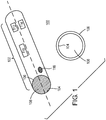
- Fig. 1 illustrates an electronic smoking article accessory 100 in accordance with an exemplary embodiment of the present disclosure.
- the accessory 100 includes a hollow cylindrical body 102 having inner and outer surfaces 104, 106.
- the body 102 can be a sleeve formed of a durable and flexible material, which can allow it to be slidably and removably mounted on an outer housing of an electronic smoking article.
- the body 102 can be formed of materials such as Kevlar®, or other high strength fabrics.
- suitable materials for the body can include, for example, rubber, plastics, metals, or any suitable combination thereof, that will allow for a tight and secure fit of the accessory 100 around the housing of the electronic smoking article.
- the body 102 has a hollow opening 108 that is of a sufficient diameter to receive and encase (e.g., surround or envelop) an electronic smoking article.
- the accessory 100 is made of a durable foam-like material and has hollow opening 108 smaller than a diameter of the electronic smoking article, such that the body 102 can be tightly or securely fit to the housing of the electronic smoking article.
- the accessory 100 can include a display 110 disposed on an outer surface 106 of the body 102.
- the display 110 include a liquid crystal display configured to operate in a low voltage range of 1.5 - 2V.
- the accessory 100 can also have an LED 114 and a speaker 116 disposed on the outer surface 106 to provide auditory and visual indications to the user regarding an operational or functional status of the accessory 100 or regarding a smoking topography.
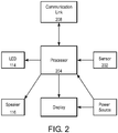
- Fig. 2 illustrates an electronic circuit 200 of an electronic smoking article accessory in accordance with an exemplary embodiment of the present disclosure.
- the electronic circuit 200 of the accessory 100 includes a sensor 202, a processor 204, the display 110, and the power source 112. Each of these components can be fully or partially embedded between the inner and outer surfaces 104, 106 of the accessory body 102.
- the sensor 202 can be used to detect an emission of the electronic smoking article.
- various components of an electronic smoking article such as a power supply, light emitting diode (LED), heating element, signal generator can emit an electromagnetic field or signal.
- the sensor can be configured to detect when the field or signal is emitted and determine that a smoking event has occurred.
- an electronic smoking article can have an LED indicator that emits light each time and for the duration of a puff event.
- the sensor 202 can therefore, be disposed on, or embedded in the body 102 of the accessory 100 to detect the light emitted by the LED.
- the sensor 202 can be tuned to detect an emission of a specified frequency, such that when this frequency is detected the accessory 100 can collect topography data.
- the processor 204 can be connected to receive a signal of the sensor 202.
- the processor 204 can be any type of low-voltage programmable microcontroller or processor.
- the processor 204 can be configured with various registers (REG), timers (TMR), or counters (CNT) for measuring and collecting the topography data.
- the processor 204 can be configured to generate an interrupt upon a change in the output of the sensor 202. This change in output indicates whether a smoking event (e.g., puff start event or puff release event) has occurred in the electronic smoking article.
- the interrupts can be used to start and stop various timers or counters, as desired, whose values can be used as the puff count, puff length, or any other desired smoking topography measurement as desired.
- the processor 204 can be configured to include memory for storing configuration data as well as data stored in the registers, timers, and counters, as desired.
- the display 110 is connected to receive an output signal from the processor 204.
- the output signal can include data values associated with the measured puff count and puff length, for example.
- the display 110 can be implemented as a liquid crystal display or other suitable low-voltage (e.g., no more than 1.5 - 2V) display output type as desired.
- the power source 112 can be any of a number of known low-voltage power supplies.
- the power source 112 can include a solar or photovoltaic cell that generates power based on captured light.
- the solar cells can be disposed on an outer surface 106 of the accessory body 102.
- the power source can be implemented as one or more batteries, such as an alkaline cell or variant that individually provides up to 1.5V. Any number of cells can be combined so that sufficient power can be supplied to the processor 204 during operation.
- the accessory 100 can also include at least one LED 114 and a speaker 116 that provide aural and visual indications to a user regarding an operational or functional status of the accessory 100, and/or an indication of specified user behavior.
- the LED 114 can be configured to emit light of a specified color or in a specified flash sequence according to whether a battery charge is low, a malfunction has occurred in the processor, the accessory is off or in a sleep mode, puff status, etc.
- the speaker 116 can be used to output various tones for indicating, for example, a battery status, puff status, power on or off event, etc.
- the accessory 100 can include a communications link 206, which can be configured to provide a bi-directional wired or wireless connection to an external device.
- the communication link 206 can be a Universal Serial Bus (USB), a Recommended Standard 232 (RS-232) family of standards.
- the wired configuration can provide bidirectional communication and also power up to 5V DC.
- the communications link 206 can be implemented as Bluetooth, Infrared Data Association (IrDA), radio-frequency (RF), cellular, or other suitable wireless communication standard as desired.
- the communication link 206 is connected to the processor 204 to transfer smoking topography data to the external device and/or the transfer configuration data to the processor 204.
- the communication link 206 can be configured to allow for bidirectional communication of user data, control data, and/or configuration data between the processor 204 and an external device or processor.
- the processor 204 can be configured to be specially programmed and/or configured to execute a process recorded on a non-transitory computer-readable recording medium, such as a hard disk drive, flash memory, optical memory, or any other type of non-volatile memory as desired.
- the executable data for the process being transferrable or transferred to the processor 204 via the communication link 206.
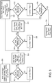
- Fig. 3 illustrates a method for generating smoking topography data in an electronic smoking article accessory in accordance with an exemplary embodiment of the present disclosure.
- the processor initializes an idle timer (Timer0) to measure the length of a non-smoking time segment.
- the processor 204 assigns a pin as an interrupt (INTO) to the output of the sensor 202.
- the processor 204 monitors the sensor output to determine whether a puff start event has occurred. When the sensor outputs a high signal, the interrupt INTO is generated.
- the idle timer (Timer0) is stopped and the puff length timer (Timer1) is started and the puff count counter (CNT0) is incremented.
- the values of Timer1 and CNT0 are output to display 110 and can remain as an output until the accessory 100 is powered down or reset.
- the processor 204 again monitors the sensor output to determine whether a puff release event has occurred. If the sensor output remains high, then no puff release event has occurred and, as shown at step 308, the Timer1 is incremented. The values of Timer1 and CNT0 are output to the display 110.
- the processor 204 monitors the output of the sensor for the next puff start event. If no puff start event is detected then the Timer0 is incremented (step 314). At step 316, the processor 204 determines whether the Timer0 has exceeded a specified value (e.g., TimeOutValue), and if so, the processor 204 generates an interrupt (INT1) to stop the Timer0 and power down (step 318).
- a specified value e.g., TimeOutValue
- step 312 if a next puff start event is detected (step 320), the Timer0 is stopped and reset, the puff count counter (CNT1) is incremented, and the puff length timer (Timer1) is started.
- the values of Timer0, Timer1, and CNT0 are output to the display 110.
- processing continues at step 306.
- the teachings herein are applicable to all forms of electronic smoking articles, such as electronic cigarettes, cigars, pipes, hookas, and other suitable forms of electronic smoking articles as desired, regardless of their size and shape.
- the display 110 can be used to output any of a number of status messages to the user.
Landscapes
- Health & Medical Sciences (AREA)
- Life Sciences & Earth Sciences (AREA)
- Chemical & Material Sciences (AREA)
- General Health & Medical Sciences (AREA)
- Engineering & Computer Science (AREA)
- Physics & Mathematics (AREA)
- Analytical Chemistry (AREA)
- Biochemistry (AREA)
- General Physics & Mathematics (AREA)
- Immunology (AREA)
- Pathology (AREA)
- Human Computer Interaction (AREA)
- Photometry And Measurement Of Optical Pulse Characteristics (AREA)
- Investigating, Analyzing Materials By Fluorescence Or Luminescence (AREA)
- Manufacture Of Tobacco Products (AREA)
- Anesthesiology (AREA)
- General Chemical & Material Sciences (AREA)
- Bioinformatics & Cheminformatics (AREA)
- Pulmonology (AREA)
- Chemical Kinetics & Catalysis (AREA)
- Biomedical Technology (AREA)
- Heart & Thoracic Surgery (AREA)
- Hematology (AREA)
- Animal Behavior & Ethology (AREA)
- Public Health (AREA)
- Veterinary Medicine (AREA)
- Length Measuring Devices By Optical Means (AREA)
Description
- This disclosure relates to an electronic smoking article, and particularly to an accessory for obtaining smoking topography data that attaches to an e-cigarette housing.
- Electronic smoking articles including electronic cigarettes or e-cigarettes may use a liquid as the aerosol-forming substrate and are capable of reducing second-hand smoke, while permitting a smoker to selectively suspend and reinitiate smoking. These devices can include a cartridge that contains the aerosol forming substrate. The substrate can come in various forms such as a solid or liquid and releases an aerosol gas to the smoker following the appropriate application of heat through a heating element. The heating element is powered through a power supply, such as a battery. The heating of the aerosol substrate is triggered via an e-puff sequence initiated by the user.
- Various systems have been described which collect data based on the smoking topography of the individual. For example,
US 2012/0291791 discloses a nicotine delivery reduction system having a breath monitor that tracks nicotine solution usage, usage frequency, and breath characteristics. A flow controller is used to regulate the levels of nicotine or nicotine solution provided to a user based on monitored user habits and characteristics.US 2011/0036346 discloses a personal inhalation device that includes a logic circuit that can be programmed to limit an amount of nicotine media atomized during a puff, and the minimum time interval between activations of the atomizing device, for example. The logic circuit can be programmed to retain device operation information such as puffs per day, puffs per minute, cartridges used, average use, and other usage information as desired. The collected data is stored in memory and can be later downloaded to an external device. -
US 2011/0265806 is directed to an electronic smoking article that includes a controller that carries out various operations on the device and a memory that stores instructions to be executed by the controller and may store usage information, product information, and user information. For example, the usage information can include a smoking liquid level in the container, how many containers have been consumed, and an amount of nicotine consumed. The product information can include a model number and serial number; and the user information can include name, sex, age, address, job, educational background, interests, and hobbies among the information. This data can be stored in memory until downloaded through any suitable wired or wireless connection.WO2004/047570 A2 discloses a smoking behaviour analyser that comprises fluid flow pressure drop detection means and smoke density detection means for detecting the optical density of the smoke; signal conversion means to convert signals obtained into data; and data processing means operable to process data and provide a calculation of a delivery value of particulate phase smoke components from a smoking article. - The exemplary embodiments of the present disclosure provide an accessory that can be mounted on or attached to the outer housing of an electronic smoking article and provide a measure of smoking topography data. This accessory can be advantageous in situations where an electronic smoking article does not have a manner of monitoring smoking topography data for a smoking event. The accessory can be configured to be non-intrusive and provide minimal additional weight or size to the electronic smoking article to which it is mounted or attached. The accessory can include a sensor that detects an electromagnetic or light emission of the electronic smoking article during a smoking event (e.g., puff event) of a user. Based on the detected emission a processor can measure the length (e.g., time interval, duration in time) of the smoking event, the number of smoking events, or other desired properties of the smoking event as desired. The accessory can include a display that outputs an alphanumeric representation of the measurements.
- An exemplary first embodiment is directed to an apparatus configured to be detachably mounted on an outer surface of a housing of an electronic smoking article, the apparatus comprising: a hollow body having inner and outer surfaces; a sensor embedded in the body, and configured to detect an emission of the electronic smoking article; a processor embedded in the body, the processor being configured to generate smoking topography data based on the emission; and a display that generates an output based on the smoking topography data provided by the processor.
- An exemplary second embodiment is directed to a method of generating smoking topography data from an electronic smoking article, comprising: detecting a emission of the smoking article; generating smoking topography data based on the emission; and outputting the smoking topography data to a display device.
- Exemplary embodiments of the present disclosure are described in more detail with reference to the attached drawings.
-
Fig. 1 illustrates an electronic smoking article accessory in accordance with an exemplary embodiment of the present disclosure. -
Fig. 2 illustrates electronic circuitry of an electronic smoking article accessory in accordance with an exemplary embodiment of the present disclosure. -
Fig. 3 illustrates a method for generating smoking topography data in an electronic smoking article accessory in accordance with an exemplary embodiment of the present disclosure. -
Fig. 1 illustrates an electronicsmoking article accessory 100 in accordance with an exemplary embodiment of the present disclosure. Theaccessory 100 includes a hollowcylindrical body 102 having inner andouter surfaces body 102 can be a sleeve formed of a durable and flexible material, which can allow it to be slidably and removably mounted on an outer housing of an electronic smoking article. In an exemplary embodiment, thebody 102 can be formed of materials such as Kevlar®, or other high strength fabrics. However, other suitable materials for the body can include, for example, rubber, plastics, metals, or any suitable combination thereof, that will allow for a tight and secure fit of theaccessory 100 around the housing of the electronic smoking article. Thebody 102 has ahollow opening 108 that is of a sufficient diameter to receive and encase (e.g., surround or envelop) an electronic smoking article. In an exemplary embodiment, theaccessory 100 is made of a durable foam-like material and hashollow opening 108 smaller than a diameter of the electronic smoking article, such that thebody 102 can be tightly or securely fit to the housing of the electronic smoking article. - As shown in
Fig. 1 , theaccessory 100 can include adisplay 110 disposed on anouter surface 106 of thebody 102. Thedisplay 110 include a liquid crystal display configured to operate in a low voltage range of 1.5 - 2V. In an exemplary embodiment, theaccessory 100 can also have anLED 114 and aspeaker 116 disposed on theouter surface 106 to provide auditory and visual indications to the user regarding an operational or functional status of theaccessory 100 or regarding a smoking topography. -
Fig. 2 illustrates an electronic circuit 200 of an electronic smoking article accessory in accordance with an exemplary embodiment of the present disclosure. As shown inFig. 2 , the electronic circuit 200 of theaccessory 100 includes asensor 202, aprocessor 204, thedisplay 110, and thepower source 112. Each of these components can be fully or partially embedded between the inner andouter surfaces accessory body 102. - The
sensor 202 can be used to detect an emission of the electronic smoking article. During a smoking event, various components of an electronic smoking article, such as a power supply, light emitting diode (LED), heating element, signal generator can emit an electromagnetic field or signal. The sensor can be configured to detect when the field or signal is emitted and determine that a smoking event has occurred. For example, in an exemplary embodiment an electronic smoking article can have an LED indicator that emits light each time and for the duration of a puff event. Thesensor 202 can therefore, be disposed on, or embedded in thebody 102 of theaccessory 100 to detect the light emitted by the LED. In other exemplary embodiments, thesensor 202 can be tuned to detect an emission of a specified frequency, such that when this frequency is detected theaccessory 100 can collect topography data. - The
processor 204 can be connected to receive a signal of thesensor 202. Theprocessor 204 can be any type of low-voltage programmable microcontroller or processor. Theprocessor 204 can be configured with various registers (REG), timers (TMR), or counters (CNT) for measuring and collecting the topography data. In an exemplary embodiment, theprocessor 204 can be configured to generate an interrupt upon a change in the output of thesensor 202. This change in output indicates whether a smoking event (e.g., puff start event or puff release event) has occurred in the electronic smoking article. The interrupts can be used to start and stop various timers or counters, as desired, whose values can be used as the puff count, puff length, or any other desired smoking topography measurement as desired. Theprocessor 204 can be configured to include memory for storing configuration data as well as data stored in the registers, timers, and counters, as desired. - The
display 110 is connected to receive an output signal from theprocessor 204. The output signal can include data values associated with the measured puff count and puff length, for example. Thedisplay 110 can be implemented as a liquid crystal display or other suitable low-voltage (e.g., no more than 1.5 - 2V) display output type as desired. - The
power source 112 can be any of a number of known low-voltage power supplies. For example, as already discussed, thepower source 112 can include a solar or photovoltaic cell that generates power based on captured light. As shown inFig. 1 , the solar cells can be disposed on anouter surface 106 of theaccessory body 102. In an exemplary embodiment, the power source can be implemented as one or more batteries, such as an alkaline cell or variant that individually provides up to 1.5V. Any number of cells can be combined so that sufficient power can be supplied to theprocessor 204 during operation. - In an exemplary embodiment, the
accessory 100 can also include at least oneLED 114 and aspeaker 116 that provide aural and visual indications to a user regarding an operational or functional status of theaccessory 100, and/or an indication of specified user behavior. For example, theLED 114 can be configured to emit light of a specified color or in a specified flash sequence according to whether a battery charge is low, a malfunction has occurred in the processor, the accessory is off or in a sleep mode, puff status, etc. Similarly, thespeaker 116 can be used to output various tones for indicating, for example, a battery status, puff status, power on or off event, etc. - In an exemplary embodiment, the
accessory 100 can include a communications link 206, which can be configured to provide a bi-directional wired or wireless connection to an external device. In a wired configuration, the communication link 206 can be a Universal Serial Bus (USB), a Recommended Standard 232 (RS-232) family of standards. The wired configuration can provide bidirectional communication and also power up to 5V DC. In a wireless configuration, the communications link 206 can be implemented as Bluetooth, Infrared Data Association (IrDA), radio-frequency (RF), cellular, or other suitable wireless communication standard as desired. The communication link 206 is connected to theprocessor 204 to transfer smoking topography data to the external device and/or the transfer configuration data to theprocessor 204. The communication link 206 can be configured to allow for bidirectional communication of user data, control data, and/or configuration data between theprocessor 204 and an external device or processor. With regard to the configuration and control data, theprocessor 204 can be configured to be specially programmed and/or configured to execute a process recorded on a non-transitory computer-readable recording medium, such as a hard disk drive, flash memory, optical memory, or any other type of non-volatile memory as desired. The executable data for the process being transferrable or transferred to theprocessor 204 via the communication link 206. -
Fig. 3 illustrates a method for generating smoking topography data in an electronic smoking article accessory in accordance with an exemplary embodiment of the present disclosure. As shown inFig. 3 , at power up or system reset (step 300), the processor initializes an idle timer (Timer0) to measure the length of a non-smoking time segment. At power up, theprocessor 204 assigns a pin as an interrupt (INTO) to the output of thesensor 202. Atstep 302, theprocessor 204 monitors the sensor output to determine whether a puff start event has occurred. When the sensor outputs a high signal, the interrupt INTO is generated. As shown atstep 304, the idle timer (Timer0) is stopped and the puff length timer (Timer1) is started and the puff count counter (CNT0) is incremented. The values of Timer1 and CNT0 are output to display 110 and can remain as an output until theaccessory 100 is powered down or reset. Atstep 306, theprocessor 204 again monitors the sensor output to determine whether a puff release event has occurred. If the sensor output remains high, then no puff release event has occurred and, as shown atstep 308, the Timer1 is incremented. The values of Timer1 and CNT0 are output to thedisplay 110. When, atstep 310, the puff release event is detected, then the interrupt INTO is again generated, the Timer1 is stopped and the non-smoking interval timer or idle timer (Timer0) is started. The values of Timer0, Timer1, and CNT0 are output to the display. Atstep 312, theprocessor 204 monitors the output of the sensor for the next puff start event. If no puff start event is detected then the Timer0 is incremented (step 314). Atstep 316, theprocessor 204 determines whether the Timer0 has exceeded a specified value (e.g., TimeOutValue), and if so, theprocessor 204 generates an interrupt (INT1) to stop the Timer0 and power down (step 318). If however, the Timer0 has not exceeded a specified value then processing returns to step 312.
Atstep 312, if a next puff start event is detected (step 320), the Timer0 is stopped and reset, the puff count counter (CNT1) is incremented, and the puff length timer (Timer1) is started. The values of Timer0, Timer1, and CNT0 are output to thedisplay 110. Processing continues atstep 306.
The teachings herein are applicable to all forms of electronic smoking articles, such as electronic cigarettes, cigars, pipes, hookas, and other suitable forms of electronic smoking articles as desired, regardless of their size and shape.
In an exemplary embodiment, during the exemplary method described above thedisplay 110 can be used to output any of a number of status messages to the user. While the disclosure has been illustrated and described in detail in the drawings and foregoing description, such illustration and description are to be considered illustrative or exemplary and not restrictive; the disclosure is not limited to the disclosed exemplary embodiments. Other variations to the disclosed exemplary embodiments can be understood and effected by those skilled in the art and practicing the claimed disclosure, from a study of the drawings, the disclosure, and the appended claims. In the claims, the word "comprising" does not exclude other elements or steps, and the indefinite article "a" or "an" does not exclude a plurality. The mere fact that certain measures are recited in mutually different dependent claims does not indicate that a combination of these measures cannot be used to advantage. Any reference symbols in the claims should not be construed as limiting the scope.
Thus, it will be appreciated by those skilled in the art that the present disclosure can be embodied in other specific forms without departing from the essential characteristics thereof. The presently disclosed embodiments are therefore considered in all respects to be illustrative and not restricted. The scope of the disclosure is indicated by the appended claims rather than the foregoing description and all changes that come within the meaning and range and equivalence thereof are intended to be embraced therein.
Claims (15)
- An apparatus (100) configured to be detachably mounted on an outer surface of a housing of an electronic smoking article, the apparatus (100) comprising:a hollow body (102) having inner and outer surfaces (104, 106);a sensor (202) embedded in the body (102), and configured to detect an emission of the electronic smoking article;a processor (204) embedded in the body (102), the processor (204) being configured to generate smoking topography data based on the emission; anda display (110) that generates an output based on the smoking topography data provided by the processor (204).
- The apparatus (100) of claim 1, wherein the sensor (202) is embedded in a circuit (200) of the processor (204).
- The apparatus (100) of claim 1, wherein the sensor (202) detects an electromagnetic field or signal emitted by a heating element of the smoking article.
- The apparatus (100) of claim 1, wherein the sensor (202) detects a light emitted by a light source of the electronic smoking article.
- The apparatus (100) of claim 1, wherein the processor (204) is configured to determine at least one of a puff count and a puff length upon detection of the smoking event.
- The apparatus (100) of claim 1, wherein the display (110) is a liquid crystal display configured to generate an alphanumeric output.
- The apparatus (100) of claim 5, wherein the display (110) is a liquid crystal display configured to generate an alphanumeric output of at least one of the puff count and the puff length.
- The apparatus (100) of claim 1, comprising:
a power source (112) embedded between the inner and outer surfaces (104, 106) of the body (102), and configured to provide power to the processor (204) and the display (110). - The apparatus (100) of claim 1, comprising:
memory configured to store the smoking topography data generated by the processor (204). - A method of generating smoking topography data from an electronic smoking article, comprising:detecting an emission of the smoking article;generating smoking topography data based on the emission; andoutputting the smoking topography data to a display device (110).
- The method of claim 10, comprising:measuring at least one of a time length of the emission and a time length between emissions; andoutputting the measurement to the display device (110).
- The method of claim 10, comprising:
starting a timer when the emission is detected, and optionally stopping a timer when the emission is no longer detected, and optionally wherein the value of the timer is provided to the display (110) as a measure of puff length. - The method of claim 10, comprising:
incrementing a counter (312) each time an electromagnetic signal or field is detected, optionally wherein the value of the counter (312) is provided to the display (110) as a measure of puff count. - The method of claim 10, wherein detecting the emission comprises detecting light emitted by the smoking article.
- The method of claim 10, wherein detecting the emission comprises detecting an electromagnetic signal or field emitted by the smoking article.
Priority Applications (1)
| Application Number | Priority Date | Filing Date | Title |
|---|---|---|---|
| PL14719926T PL2967153T3 (en) | 2013-03-15 | 2014-03-12 | Accessory for electronic cigarette |
Applications Claiming Priority (2)
| Application Number | Priority Date | Filing Date | Title |
|---|---|---|---|
| US201361800026P | 2013-03-15 | 2013-03-15 | |
| PCT/US2014/024487 WO2014150898A2 (en) | 2013-03-15 | 2014-03-12 | Accessory for electronic cigarette |
Publications (2)
| Publication Number | Publication Date |
|---|---|
| EP2967153A2 EP2967153A2 (en) | 2016-01-20 |
| EP2967153B1 true EP2967153B1 (en) | 2018-05-09 |
Family
ID=50588833
Family Applications (1)
| Application Number | Title | Priority Date | Filing Date |
|---|---|---|---|
| EP14719926.9A Not-in-force EP2967153B1 (en) | 2013-03-15 | 2014-03-12 | Accessory for electronic cigarette |
Country Status (13)
| Country | Link |
|---|---|
| US (3) | US11058154B2 (en) |
| EP (1) | EP2967153B1 (en) |
| KR (1) | KR20160040443A (en) |
| CN (1) | CN105377064A (en) |
| AR (1) | AR095633A1 (en) |
| CA (1) | CA2906458A1 (en) |
| ES (1) | ES2681603T3 (en) |
| MA (1) | MA38414B1 (en) |
| MY (1) | MY184440A (en) |
| PL (1) | PL2967153T3 (en) |
| RU (1) | RU2651475C2 (en) |
| UA (1) | UA117129C2 (en) |
| WO (1) | WO2014150898A2 (en) |
Families Citing this family (53)
| Publication number | Priority date | Publication date | Assignee | Title |
|---|---|---|---|---|
| US10244793B2 (en) | 2005-07-19 | 2019-04-02 | Juul Labs, Inc. | Devices for vaporization of a substance |
| US10279934B2 (en) | 2013-03-15 | 2019-05-07 | Juul Labs, Inc. | Fillable vaporizer cartridge and method of filling |
| MA38414B1 (en) * | 2013-03-15 | 2016-09-30 | Altria Client Services Llc | Accessory for electronic cigarette |
| US10638792B2 (en) | 2013-03-15 | 2020-05-05 | Juul Labs, Inc. | Securely attaching cartridges for vaporizer devices |
| US20160371437A1 (en) | 2013-06-21 | 2016-12-22 | Fontem Holdings 4 B.V. | Clinical interface |
| US10039321B2 (en) | 2013-11-12 | 2018-08-07 | Vmr Products Llc | Vaporizer |
| CN106102811B (en) | 2013-11-21 | 2020-03-10 | 方特慕控股第四私人有限公司 | Apparatus, method and system for recording smoking data |
| US10076139B2 (en) | 2013-12-23 | 2018-09-18 | Juul Labs, Inc. | Vaporizer apparatus |
| US10159282B2 (en) | 2013-12-23 | 2018-12-25 | Juul Labs, Inc. | Cartridge for use with a vaporizer device |
| US20160366947A1 (en) | 2013-12-23 | 2016-12-22 | James Monsees | Vaporizer apparatus |
| USD842536S1 (en) | 2016-07-28 | 2019-03-05 | Juul Labs, Inc. | Vaporizer cartridge |
| US10058129B2 (en) | 2013-12-23 | 2018-08-28 | Juul Labs, Inc. | Vaporization device systems and methods |
| USD825102S1 (en) | 2016-07-28 | 2018-08-07 | Juul Labs, Inc. | Vaporizer device with cartridge |
| ES2903145T3 (en) | 2013-12-23 | 2022-03-31 | Juul Labs Int Inc | Vaporization device systems and methods |
| WO2015165059A1 (en) * | 2014-04-30 | 2015-11-05 | 吉瑞高新科技股份有限公司 | Electronic cigarette and electronic cigarette light emission control method |
| GB2546934B (en) * | 2014-11-11 | 2018-04-11 | Jt Int Sa | Electronic vapour inhalers |
| KR102627987B1 (en) | 2014-12-05 | 2024-01-22 | 쥴 랩스, 인크. | Calibrated dose control |
| WO2016210242A1 (en) | 2015-06-25 | 2016-12-29 | Altria Client Services Llc | Electronic vaping device having pressure sensor |
| WO2017023589A1 (en) * | 2015-08-03 | 2017-02-09 | Virginia Commonwealth University | Airflow puff topography measurement device and method |
| EP3334296B2 (en) | 2015-08-14 | 2023-04-05 | Philip Morris Products S.A. | An electrically operated smoking device including a compact system for identifying smoking articles in the device |
| US20170059554A1 (en) * | 2015-09-02 | 2017-03-02 | R. J. Reynolds Tobacco Company | Method for monitoring use of a tobacco product |
| US20170215478A1 (en) | 2016-01-28 | 2017-08-03 | Stratos Product Development Llc | Vapor delivery systems and methods |
| WO2017139595A1 (en) | 2016-02-11 | 2017-08-17 | Pax Labs, Inc. | Fillable vaporizer cartridge and method of filling |
| US10405582B2 (en) | 2016-03-10 | 2019-09-10 | Pax Labs, Inc. | Vaporization device with lip sensing |
| USD849996S1 (en) | 2016-06-16 | 2019-05-28 | Pax Labs, Inc. | Vaporizer cartridge |
| USD836541S1 (en) | 2016-06-23 | 2018-12-25 | Pax Labs, Inc. | Charging device |
| USD851830S1 (en) | 2016-06-23 | 2019-06-18 | Pax Labs, Inc. | Combined vaporizer tamp and pick tool |
| USD848057S1 (en) | 2016-06-23 | 2019-05-07 | Pax Labs, Inc. | Lid for a vaporizer |
| US10231485B2 (en) * | 2016-07-08 | 2019-03-19 | Rai Strategic Holdings, Inc. | Radio frequency to direct current converter for an aerosol delivery device |
| US10051893B2 (en) | 2016-07-25 | 2018-08-21 | Fontem Holdings 1 B.V. | Apparatus and method for communication and negotiation of charge rate between electronic smoking device and charger |
| CA3032761C (en) | 2016-08-04 | 2022-06-07 | Japan Tobacco Inc. | Flavor inhaler with oscillator |
| CN106263035A (en) * | 2016-08-08 | 2017-01-04 | 深圳市海派特光伏科技有限公司 | Electronic cigarette and nicotine detection method |
| US10897930B2 (en) | 2017-05-24 | 2021-01-26 | Altria Client Services Llc | Topography apparatus for electronic vaping device |
| GB201709201D0 (en) | 2017-06-09 | 2017-07-26 | Nicoventures Holdings Ltd | Electronic aerosol provision system |
| USD887632S1 (en) | 2017-09-14 | 2020-06-16 | Pax Labs, Inc. | Vaporizer cartridge |
| JP7397790B2 (en) | 2017-10-06 | 2023-12-13 | フィリップ・モーリス・プロダクツ・ソシエテ・アノニム | Visual user interface for aerosol generators |
| US11290182B2 (en) | 2018-03-05 | 2022-03-29 | Altria Client Services Llc | Methods and devices for communication of data between electronic vaping device and external device |
| GB201803648D0 (en) | 2018-03-07 | 2018-04-25 | Nicoventures Trading Ltd | Electronic aerosol provision system |
| JP7497304B2 (en) | 2018-07-10 | 2024-06-10 | フィリップ・モーリス・プロダクツ・ソシエテ・アノニム | Aerosol generating system with air quality sensor |
| GB201815524D0 (en) * | 2018-09-24 | 2018-11-07 | Nerudia Ltd | Smoking substitute device |
| US11676438B2 (en) | 2019-04-02 | 2023-06-13 | Rai Strategic Holdings, Inc. | Authentication and age verification for an aerosol delivery device |
| EP4190190A1 (en) * | 2020-04-23 | 2023-06-07 | JT International SA | Method of operating an aerosol-generating device |
| CN115460944A (en) * | 2020-04-23 | 2022-12-09 | 日本烟草国际股份有限公司 | Method for operating an aerosol generating device |
| WO2021260691A1 (en) * | 2020-06-22 | 2021-12-30 | Arama Asaf | Smoking cessation device for actively shortening and reducing smoking in the daily routine of the smoker |
| KR102553827B1 (en) | 2020-06-26 | 2023-07-10 | 주식회사 케이티앤지 | Auxiliary device for aerosol generating apparatus and aerosol generating system including the same |
| US11636870B2 (en) | 2020-08-20 | 2023-04-25 | Denso International America, Inc. | Smoking cessation systems and methods |
| US11760169B2 (en) | 2020-08-20 | 2023-09-19 | Denso International America, Inc. | Particulate control systems and methods for olfaction sensors |
| US12017506B2 (en) | 2020-08-20 | 2024-06-25 | Denso International America, Inc. | Passenger cabin air control systems and methods |
| US11760170B2 (en) | 2020-08-20 | 2023-09-19 | Denso International America, Inc. | Olfaction sensor preservation systems and methods |
| US11881093B2 (en) | 2020-08-20 | 2024-01-23 | Denso International America, Inc. | Systems and methods for identifying smoking in vehicles |
| US11828210B2 (en) | 2020-08-20 | 2023-11-28 | Denso International America, Inc. | Diagnostic systems and methods of vehicles using olfaction |
| US11813926B2 (en) | 2020-08-20 | 2023-11-14 | Denso International America, Inc. | Binding agent and olfaction sensor |
| US11932080B2 (en) | 2020-08-20 | 2024-03-19 | Denso International America, Inc. | Diagnostic and recirculation control systems and methods |
Family Cites Families (17)
| Publication number | Priority date | Publication date | Assignee | Title |
|---|---|---|---|---|
| US4771381A (en) | 1987-04-20 | 1988-09-13 | R. J. Reynolds Tobacco Company | Method and system for effecting sensory evaluation of a smoking product |
| US5665262A (en) * | 1991-03-11 | 1997-09-09 | Philip Morris Incorporated | Tubular heater for use in an electrical smoking article |
| US5505214A (en) * | 1991-03-11 | 1996-04-09 | Philip Morris Incorporated | Electrical smoking article and method for making same |
| US5902501A (en) | 1997-10-20 | 1999-05-11 | Philip Morris Incorporated | Lighter actuation system |
| DE60203291T2 (en) | 2001-06-07 | 2006-04-13 | British American Tobacco (Investments) Ltd. | CIGARETTES MONITORING |
| US6803545B2 (en) * | 2002-06-05 | 2004-10-12 | Philip Morris Incorporated | Electrically heated smoking system and methods for supplying electrical power from a lithium ion power source |
| GB0227715D0 (en) | 2002-11-28 | 2003-01-08 | British American Tobacco Co | Smoking behaviour analyser |
| US7615700B2 (en) * | 2007-10-18 | 2009-11-10 | Diclaudio Mark | Training device for brass musical instrument |
| CN201379072Y (en) * | 2009-02-11 | 2010-01-13 | 韩力 | Improved atomizing electronic cigarette |
| US8851068B2 (en) * | 2009-04-21 | 2014-10-07 | Aj Marketing Llc | Personal inhalation devices |
| EP2319334A1 (en) | 2009-10-27 | 2011-05-11 | Philip Morris Products S.A. | A smoking system having a liquid storage portion |
| PL2563172T5 (en) * | 2010-04-30 | 2022-08-29 | Fontem Holdings 4 B.V. | Electronic smoking device |
| DK3508083T3 (en) * | 2010-08-24 | 2021-10-11 | Jt Int Sa | INHALATION DEVICE INCLUDING SUBSTANCE USE CONTROL |
| US20120291791A1 (en) | 2011-05-19 | 2012-11-22 | Neurofocus, Inc. | Methods and apparatus for nicotine delivery reduction |
| US20140230835A1 (en) * | 2013-02-21 | 2014-08-21 | Sarmad Saliman | Disposable electronic cigarette with power shut off protection |
| US9560883B2 (en) * | 2013-03-15 | 2017-02-07 | Altria Client Services Llc | Electronic smoking articles |
| MA38414B1 (en) * | 2013-03-15 | 2016-09-30 | Altria Client Services Llc | Accessory for electronic cigarette |
-
2014
- 2014-03-12 MA MA38414A patent/MA38414B1/en unknown
- 2014-03-12 US US14/205,813 patent/US11058154B2/en active Active
- 2014-03-12 RU RU2015144189A patent/RU2651475C2/en not_active IP Right Cessation
- 2014-03-12 WO PCT/US2014/024487 patent/WO2014150898A2/en active Application Filing
- 2014-03-12 CN CN201480019839.8A patent/CN105377064A/en active Pending
- 2014-03-12 KR KR1020157025123A patent/KR20160040443A/en not_active Application Discontinuation
- 2014-03-12 ES ES14719926.9T patent/ES2681603T3/en active Active
- 2014-03-12 EP EP14719926.9A patent/EP2967153B1/en not_active Not-in-force
- 2014-03-12 MY MYPI2015002334A patent/MY184440A/en unknown
- 2014-03-12 CA CA2906458A patent/CA2906458A1/en not_active Abandoned
- 2014-03-12 PL PL14719926T patent/PL2967153T3/en unknown
- 2014-03-17 AR ARP140101260A patent/AR095633A1/en unknown
- 2014-12-03 UA UAA201509971A patent/UA117129C2/en unknown
-
2021
- 2021-06-21 US US17/353,052 patent/US11684089B2/en active Active
-
2023
- 2023-05-12 US US18/316,515 patent/US12121072B2/en active Active
Non-Patent Citations (1)
| Title |
|---|
| None * |
Also Published As
| Publication number | Publication date |
|---|---|
| ES2681603T3 (en) | 2018-09-14 |
| WO2014150898A2 (en) | 2014-09-25 |
| AR095633A1 (en) | 2015-10-28 |
| US11684089B2 (en) | 2023-06-27 |
| US20230276857A1 (en) | 2023-09-07 |
| RU2651475C2 (en) | 2018-04-19 |
| KR20160040443A (en) | 2016-04-14 |
| MY184440A (en) | 2021-04-01 |
| EP2967153A2 (en) | 2016-01-20 |
| US20210307404A1 (en) | 2021-10-07 |
| WO2014150898A3 (en) | 2014-12-24 |
| RU2015144189A (en) | 2017-04-25 |
| RU2015144189A3 (en) | 2018-03-14 |
| US20140278258A1 (en) | 2014-09-18 |
| UA117129C2 (en) | 2018-06-25 |
| MA38414B1 (en) | 2016-09-30 |
| MA38414A1 (en) | 2016-02-29 |
| CN105377064A (en) | 2016-03-02 |
| CA2906458A1 (en) | 2014-09-25 |
| US12121072B2 (en) | 2024-10-22 |
| PL2967153T3 (en) | 2018-09-28 |
| US11058154B2 (en) | 2021-07-13 |
Similar Documents
| Publication | Publication Date | Title |
|---|---|---|
| US11684089B2 (en) | Accessory for electronic cigarette | |
| US10888116B2 (en) | System and method of obtaining smoking topography data | |
| US20220088321A1 (en) | Inhalation device including substance usage controls | |
| KR20230038723A (en) | How to care for your aerosol generating device | |
| CN115768295A (en) | Method of managing an aerosol-generating device |
Legal Events
| Date | Code | Title | Description |
|---|---|---|---|
| PUAI | Public reference made under article 153(3) epc to a published international application that has entered the european phase |
Free format text: ORIGINAL CODE: 0009012 |
|
| 17P | Request for examination filed |
Effective date: 20150909 |
|
| AK | Designated contracting states |
Kind code of ref document: A2 Designated state(s): AL AT BE BG CH CY CZ DE DK EE ES FI FR GB GR HR HU IE IS IT LI LT LU LV MC MK MT NL NO PL PT RO RS SE SI SK SM TR |
|
| AX | Request for extension of the european patent |
Extension state: BA ME |
|
| DAX | Request for extension of the european patent (deleted) | ||
| 17Q | First examination report despatched |
Effective date: 20161018 |
|
| STAA | Information on the status of an ep patent application or granted ep patent |
Free format text: STATUS: EXAMINATION IS IN PROGRESS |
|
| GRAP | Despatch of communication of intention to grant a patent |
Free format text: ORIGINAL CODE: EPIDOSNIGR1 |
|
| STAA | Information on the status of an ep patent application or granted ep patent |
Free format text: STATUS: GRANT OF PATENT IS INTENDED |
|
| INTG | Intention to grant announced |
Effective date: 20171004 |
|
| GRAS | Grant fee paid |
Free format text: ORIGINAL CODE: EPIDOSNIGR3 |
|
| GRAA | (expected) grant |
Free format text: ORIGINAL CODE: 0009210 |
|
| STAA | Information on the status of an ep patent application or granted ep patent |
Free format text: STATUS: THE PATENT HAS BEEN GRANTED |
|
| AK | Designated contracting states |
Kind code of ref document: B1 Designated state(s): AL AT BE BG CH CY CZ DE DK EE ES FI FR GB GR HR HU IE IS IT LI LT LU LV MC MK MT NL NO PL PT RO RS SE SI SK SM TR |
|
| REG | Reference to a national code |
Ref country code: GB Ref legal event code: FG4D |
|
| REG | Reference to a national code |
Ref country code: CH Ref legal event code: EP Ref country code: AT Ref legal event code: REF Ref document number: 996691 Country of ref document: AT Kind code of ref document: T Effective date: 20180515 |
|
| REG | Reference to a national code |
Ref country code: IE Ref legal event code: FG4D |
|
| REG | Reference to a national code |
Ref country code: DE Ref legal event code: R096 Ref document number: 602014025211 Country of ref document: DE |
|
| REG | Reference to a national code |
Ref country code: RO Ref legal event code: EPE |
|
| REG | Reference to a national code |
Ref country code: NL Ref legal event code: FP |
|
| REG | Reference to a national code |
Ref country code: ES Ref legal event code: FG2A Ref document number: 2681603 Country of ref document: ES Kind code of ref document: T3 Effective date: 20180914 |
|
| REG | Reference to a national code |
Ref country code: LT Ref legal event code: MG4D |
|
| PG25 | Lapsed in a contracting state [announced via postgrant information from national office to epo] |
Ref country code: FI Free format text: LAPSE BECAUSE OF FAILURE TO SUBMIT A TRANSLATION OF THE DESCRIPTION OR TO PAY THE FEE WITHIN THE PRESCRIBED TIME-LIMIT Effective date: 20180509 Ref country code: BG Free format text: LAPSE BECAUSE OF FAILURE TO SUBMIT A TRANSLATION OF THE DESCRIPTION OR TO PAY THE FEE WITHIN THE PRESCRIBED TIME-LIMIT Effective date: 20180809 Ref country code: NO Free format text: LAPSE BECAUSE OF FAILURE TO SUBMIT A TRANSLATION OF THE DESCRIPTION OR TO PAY THE FEE WITHIN THE PRESCRIBED TIME-LIMIT Effective date: 20180809 Ref country code: SE Free format text: LAPSE BECAUSE OF FAILURE TO SUBMIT A TRANSLATION OF THE DESCRIPTION OR TO PAY THE FEE WITHIN THE PRESCRIBED TIME-LIMIT Effective date: 20180509 Ref country code: LT Free format text: LAPSE BECAUSE OF FAILURE TO SUBMIT A TRANSLATION OF THE DESCRIPTION OR TO PAY THE FEE WITHIN THE PRESCRIBED TIME-LIMIT Effective date: 20180509 |
|
| PG25 | Lapsed in a contracting state [announced via postgrant information from national office to epo] |
Ref country code: RS Free format text: LAPSE BECAUSE OF FAILURE TO SUBMIT A TRANSLATION OF THE DESCRIPTION OR TO PAY THE FEE WITHIN THE PRESCRIBED TIME-LIMIT Effective date: 20180509 Ref country code: HR Free format text: LAPSE BECAUSE OF FAILURE TO SUBMIT A TRANSLATION OF THE DESCRIPTION OR TO PAY THE FEE WITHIN THE PRESCRIBED TIME-LIMIT Effective date: 20180509 Ref country code: GR Free format text: LAPSE BECAUSE OF FAILURE TO SUBMIT A TRANSLATION OF THE DESCRIPTION OR TO PAY THE FEE WITHIN THE PRESCRIBED TIME-LIMIT Effective date: 20180810 Ref country code: LV Free format text: LAPSE BECAUSE OF FAILURE TO SUBMIT A TRANSLATION OF THE DESCRIPTION OR TO PAY THE FEE WITHIN THE PRESCRIBED TIME-LIMIT Effective date: 20180509 |
|
| PG25 | Lapsed in a contracting state [announced via postgrant information from national office to epo] |
Ref country code: SK Free format text: LAPSE BECAUSE OF FAILURE TO SUBMIT A TRANSLATION OF THE DESCRIPTION OR TO PAY THE FEE WITHIN THE PRESCRIBED TIME-LIMIT Effective date: 20180509 Ref country code: EE Free format text: LAPSE BECAUSE OF FAILURE TO SUBMIT A TRANSLATION OF THE DESCRIPTION OR TO PAY THE FEE WITHIN THE PRESCRIBED TIME-LIMIT Effective date: 20180509 Ref country code: CZ Free format text: LAPSE BECAUSE OF FAILURE TO SUBMIT A TRANSLATION OF THE DESCRIPTION OR TO PAY THE FEE WITHIN THE PRESCRIBED TIME-LIMIT Effective date: 20180509 Ref country code: DK Free format text: LAPSE BECAUSE OF FAILURE TO SUBMIT A TRANSLATION OF THE DESCRIPTION OR TO PAY THE FEE WITHIN THE PRESCRIBED TIME-LIMIT Effective date: 20180509 |
|
| REG | Reference to a national code |
Ref country code: DE Ref legal event code: R097 Ref document number: 602014025211 Country of ref document: DE |
|
| PG25 | Lapsed in a contracting state [announced via postgrant information from national office to epo] |
Ref country code: SM Free format text: LAPSE BECAUSE OF FAILURE TO SUBMIT A TRANSLATION OF THE DESCRIPTION OR TO PAY THE FEE WITHIN THE PRESCRIBED TIME-LIMIT Effective date: 20180509 |
|
| PLBE | No opposition filed within time limit |
Free format text: ORIGINAL CODE: 0009261 |
|
| STAA | Information on the status of an ep patent application or granted ep patent |
Free format text: STATUS: NO OPPOSITION FILED WITHIN TIME LIMIT |
|
| 26N | No opposition filed |
Effective date: 20190212 |
|
| PGFP | Annual fee paid to national office [announced via postgrant information from national office to epo] |
Ref country code: PL Payment date: 20190308 Year of fee payment: 6 Ref country code: DE Payment date: 20190327 Year of fee payment: 6 Ref country code: LU Payment date: 20190327 Year of fee payment: 6 Ref country code: FR Payment date: 20190325 Year of fee payment: 6 Ref country code: RO Payment date: 20190225 Year of fee payment: 6 Ref country code: IT Payment date: 20190322 Year of fee payment: 6 |
|
| PG25 | Lapsed in a contracting state [announced via postgrant information from national office to epo] |
Ref country code: SI Free format text: LAPSE BECAUSE OF FAILURE TO SUBMIT A TRANSLATION OF THE DESCRIPTION OR TO PAY THE FEE WITHIN THE PRESCRIBED TIME-LIMIT Effective date: 20180509 |
|
| PGFP | Annual fee paid to national office [announced via postgrant information from national office to epo] |
Ref country code: AT Payment date: 20190220 Year of fee payment: 6 Ref country code: BE Payment date: 20190327 Year of fee payment: 6 Ref country code: NL Payment date: 20190326 Year of fee payment: 6 |
|
| PGFP | Annual fee paid to national office [announced via postgrant information from national office to epo] |
Ref country code: ES Payment date: 20190401 Year of fee payment: 6 |
|
| PG25 | Lapsed in a contracting state [announced via postgrant information from national office to epo] |
Ref country code: MC Free format text: LAPSE BECAUSE OF FAILURE TO SUBMIT A TRANSLATION OF THE DESCRIPTION OR TO PAY THE FEE WITHIN THE PRESCRIBED TIME-LIMIT Effective date: 20180509 |
|
| PGFP | Annual fee paid to national office [announced via postgrant information from national office to epo] |
Ref country code: GB Payment date: 20190404 Year of fee payment: 6 |
|
| REG | Reference to a national code |
Ref country code: CH Ref legal event code: PL |
|
| PG25 | Lapsed in a contracting state [announced via postgrant information from national office to epo] |
Ref country code: AL Free format text: LAPSE BECAUSE OF FAILURE TO SUBMIT A TRANSLATION OF THE DESCRIPTION OR TO PAY THE FEE WITHIN THE PRESCRIBED TIME-LIMIT Effective date: 20180509 |
|
| PG25 | Lapsed in a contracting state [announced via postgrant information from national office to epo] |
Ref country code: CH Free format text: LAPSE BECAUSE OF NON-PAYMENT OF DUE FEES Effective date: 20190331 Ref country code: IE Free format text: LAPSE BECAUSE OF NON-PAYMENT OF DUE FEES Effective date: 20190312 Ref country code: LI Free format text: LAPSE BECAUSE OF NON-PAYMENT OF DUE FEES Effective date: 20190331 |
|
| PG25 | Lapsed in a contracting state [announced via postgrant information from national office to epo] |
Ref country code: TR Free format text: LAPSE BECAUSE OF FAILURE TO SUBMIT A TRANSLATION OF THE DESCRIPTION OR TO PAY THE FEE WITHIN THE PRESCRIBED TIME-LIMIT Effective date: 20180509 |
|
| PG25 | Lapsed in a contracting state [announced via postgrant information from national office to epo] |
Ref country code: PT Free format text: LAPSE BECAUSE OF FAILURE TO SUBMIT A TRANSLATION OF THE DESCRIPTION OR TO PAY THE FEE WITHIN THE PRESCRIBED TIME-LIMIT Effective date: 20180910 Ref country code: MT Free format text: LAPSE BECAUSE OF NON-PAYMENT OF DUE FEES Effective date: 20190312 |
|
| REG | Reference to a national code |
Ref country code: DE Ref legal event code: R119 Ref document number: 602014025211 Country of ref document: DE |
|
| PG25 | Lapsed in a contracting state [announced via postgrant information from national office to epo] |
Ref country code: RO Free format text: LAPSE BECAUSE OF NON-PAYMENT OF DUE FEES Effective date: 20200312 |
|
| REG | Reference to a national code |
Ref country code: NL Ref legal event code: MM Effective date: 20200401 |
|
| REG | Reference to a national code |
Ref country code: AT Ref legal event code: MM01 Ref document number: 996691 Country of ref document: AT Kind code of ref document: T Effective date: 20200312 |
|
| REG | Reference to a national code |
Ref country code: AT Ref legal event code: UEP Ref document number: 996691 Country of ref document: AT Kind code of ref document: T Effective date: 20180509 |
|
| REG | Reference to a national code |
Ref country code: BE Ref legal event code: MM Effective date: 20200331 |
|
| PG25 | Lapsed in a contracting state [announced via postgrant information from national office to epo] |
Ref country code: LU Free format text: LAPSE BECAUSE OF NON-PAYMENT OF DUE FEES Effective date: 20200312 Ref country code: NL Free format text: LAPSE BECAUSE OF NON-PAYMENT OF DUE FEES Effective date: 20200401 |
|
| PG25 | Lapsed in a contracting state [announced via postgrant information from national office to epo] |
Ref country code: DE Free format text: LAPSE BECAUSE OF NON-PAYMENT OF DUE FEES Effective date: 20201001 Ref country code: FR Free format text: LAPSE BECAUSE OF NON-PAYMENT OF DUE FEES Effective date: 20200331 Ref country code: AT Free format text: LAPSE BECAUSE OF NON-PAYMENT OF DUE FEES Effective date: 20200312 |
|
| PG25 | Lapsed in a contracting state [announced via postgrant information from national office to epo] |
Ref country code: BE Free format text: LAPSE BECAUSE OF NON-PAYMENT OF DUE FEES Effective date: 20200331 |
|
| GBPC | Gb: european patent ceased through non-payment of renewal fee |
Effective date: 20200312 |
|
| PG25 | Lapsed in a contracting state [announced via postgrant information from national office to epo] |
Ref country code: GB Free format text: LAPSE BECAUSE OF NON-PAYMENT OF DUE FEES Effective date: 20200312 |
|
| PG25 | Lapsed in a contracting state [announced via postgrant information from national office to epo] |
Ref country code: CY Free format text: LAPSE BECAUSE OF FAILURE TO SUBMIT A TRANSLATION OF THE DESCRIPTION OR TO PAY THE FEE WITHIN THE PRESCRIBED TIME-LIMIT Effective date: 20180509 |
|
| PG25 | Lapsed in a contracting state [announced via postgrant information from national office to epo] |
Ref country code: IS Free format text: LAPSE BECAUSE OF FAILURE TO SUBMIT A TRANSLATION OF THE DESCRIPTION OR TO PAY THE FEE WITHIN THE PRESCRIBED TIME-LIMIT Effective date: 20180909 |
|
| PG25 | Lapsed in a contracting state [announced via postgrant information from national office to epo] |
Ref country code: HU Free format text: LAPSE BECAUSE OF FAILURE TO SUBMIT A TRANSLATION OF THE DESCRIPTION OR TO PAY THE FEE WITHIN THE PRESCRIBED TIME-LIMIT; INVALID AB INITIO Effective date: 20140312 |
|
| REG | Reference to a national code |
Ref country code: ES Ref legal event code: FD2A Effective date: 20210802 |
|
| PG25 | Lapsed in a contracting state [announced via postgrant information from national office to epo] |
Ref country code: IT Free format text: LAPSE BECAUSE OF NON-PAYMENT OF DUE FEES Effective date: 20200312 |
|
| PG25 | Lapsed in a contracting state [announced via postgrant information from national office to epo] |
Ref country code: ES Free format text: LAPSE BECAUSE OF NON-PAYMENT OF DUE FEES Effective date: 20200313 |
|
| PG25 | Lapsed in a contracting state [announced via postgrant information from national office to epo] |
Ref country code: MK Free format text: LAPSE BECAUSE OF FAILURE TO SUBMIT A TRANSLATION OF THE DESCRIPTION OR TO PAY THE FEE WITHIN THE PRESCRIBED TIME-LIMIT Effective date: 20180509 |
|
| PG25 | Lapsed in a contracting state [announced via postgrant information from national office to epo] |
Ref country code: PL Free format text: LAPSE BECAUSE OF NON-PAYMENT OF DUE FEES Effective date: 20200312 |
|
| P01 | Opt-out of the competence of the unified patent court (upc) registered |
Effective date: 20230525 |