EP2966578B1 - Information processing apparatus, information processing method, program, and storage medium - Google Patents
Information processing apparatus, information processing method, program, and storage medium Download PDFInfo
- Publication number
- EP2966578B1 EP2966578B1 EP15175709.3A EP15175709A EP2966578B1 EP 2966578 B1 EP2966578 B1 EP 2966578B1 EP 15175709 A EP15175709 A EP 15175709A EP 2966578 B1 EP2966578 B1 EP 2966578B1
- Authority
- EP
- European Patent Office
- Prior art keywords
- recognized
- scan image
- text
- recognized cell
- character images
- Prior art date
- Legal status (The legal status is an assumption and is not a legal conclusion. Google has not performed a legal analysis and makes no representation as to the accuracy of the status listed.)
- Active
Links
- 230000010365 information processing Effects 0.000 title claims description 23
- 238000003672 processing method Methods 0.000 title claims 6
- 230000008859 change Effects 0.000 claims description 42
- 238000000034 method Methods 0.000 claims description 22
- 238000012015 optical character recognition Methods 0.000 claims description 4
- 238000004590 computer program Methods 0.000 claims description 2
- 230000006870 function Effects 0.000 description 8
- 241000237519 Bivalvia Species 0.000 description 3
- 235000020639 clam Nutrition 0.000 description 3
- 230000009471 action Effects 0.000 description 2
- 230000005859 cell recognition Effects 0.000 description 2
- 239000003086 colorant Substances 0.000 description 2
- 238000012217 deletion Methods 0.000 description 2
- 230000037430 deletion Effects 0.000 description 2
- 238000010586 diagram Methods 0.000 description 2
- 230000003287 optical effect Effects 0.000 description 1
- 230000008569 process Effects 0.000 description 1
- 238000005549 size reduction Methods 0.000 description 1
- 230000008685 targeting Effects 0.000 description 1
Images


Classifications
-
- H—ELECTRICITY
- H04—ELECTRIC COMMUNICATION TECHNIQUE
- H04N—PICTORIAL COMMUNICATION, e.g. TELEVISION
- H04N1/00—Scanning, transmission or reproduction of documents or the like, e.g. facsimile transmission; Details thereof
- H04N1/0035—User-machine interface; Control console
- H04N1/00352—Input means
-
- G—PHYSICS
- G06—COMPUTING; CALCULATING OR COUNTING
- G06F—ELECTRIC DIGITAL DATA PROCESSING
- G06F40/00—Handling natural language data
- G06F40/10—Text processing
- G06F40/103—Formatting, i.e. changing of presentation of documents
- G06F40/109—Font handling; Temporal or kinetic typography
-
- G—PHYSICS
- G06—COMPUTING; CALCULATING OR COUNTING
- G06F—ELECTRIC DIGITAL DATA PROCESSING
- G06F3/00—Input arrangements for transferring data to be processed into a form capable of being handled by the computer; Output arrangements for transferring data from processing unit to output unit, e.g. interface arrangements
- G06F3/01—Input arrangements or combined input and output arrangements for interaction between user and computer
- G06F3/048—Interaction techniques based on graphical user interfaces [GUI]
- G06F3/0484—Interaction techniques based on graphical user interfaces [GUI] for the control of specific functions or operations, e.g. selecting or manipulating an object, an image or a displayed text element, setting a parameter value or selecting a range
- G06F3/04842—Selection of displayed objects or displayed text elements
-
- G—PHYSICS
- G06—COMPUTING; CALCULATING OR COUNTING
- G06F—ELECTRIC DIGITAL DATA PROCESSING
- G06F3/00—Input arrangements for transferring data to be processed into a form capable of being handled by the computer; Output arrangements for transferring data from processing unit to output unit, e.g. interface arrangements
- G06F3/01—Input arrangements or combined input and output arrangements for interaction between user and computer
- G06F3/048—Interaction techniques based on graphical user interfaces [GUI]
- G06F3/0484—Interaction techniques based on graphical user interfaces [GUI] for the control of specific functions or operations, e.g. selecting or manipulating an object, an image or a displayed text element, setting a parameter value or selecting a range
- G06F3/04845—Interaction techniques based on graphical user interfaces [GUI] for the control of specific functions or operations, e.g. selecting or manipulating an object, an image or a displayed text element, setting a parameter value or selecting a range for image manipulation, e.g. dragging, rotation, expansion or change of colour
-
- G—PHYSICS
- G06—COMPUTING; CALCULATING OR COUNTING
- G06F—ELECTRIC DIGITAL DATA PROCESSING
- G06F40/00—Handling natural language data
- G06F40/10—Text processing
- G06F40/166—Editing, e.g. inserting or deleting
-
- G—PHYSICS
- G06—COMPUTING; CALCULATING OR COUNTING
- G06F—ELECTRIC DIGITAL DATA PROCESSING
- G06F40/00—Handling natural language data
- G06F40/10—Text processing
- G06F40/166—Editing, e.g. inserting or deleting
- G06F40/177—Editing, e.g. inserting or deleting of tables; using ruled lines
-
- G—PHYSICS
- G06—COMPUTING; CALCULATING OR COUNTING
- G06V—IMAGE OR VIDEO RECOGNITION OR UNDERSTANDING
- G06V30/00—Character recognition; Recognising digital ink; Document-oriented image-based pattern recognition
- G06V30/10—Character recognition
- G06V30/14—Image acquisition
- G06V30/146—Aligning or centring of the image pick-up or image-field
- G06V30/147—Determination of region of interest
-
- G—PHYSICS
- G06—COMPUTING; CALCULATING OR COUNTING
- G06V—IMAGE OR VIDEO RECOGNITION OR UNDERSTANDING
- G06V30/00—Character recognition; Recognising digital ink; Document-oriented image-based pattern recognition
- G06V30/40—Document-oriented image-based pattern recognition
- G06V30/41—Analysis of document content
- G06V30/412—Layout analysis of documents structured with printed lines or input boxes, e.g. business forms or tables
-
- G—PHYSICS
- G06—COMPUTING; CALCULATING OR COUNTING
- G06V—IMAGE OR VIDEO RECOGNITION OR UNDERSTANDING
- G06V30/00—Character recognition; Recognising digital ink; Document-oriented image-based pattern recognition
- G06V30/40—Document-oriented image-based pattern recognition
- G06V30/41—Analysis of document content
- G06V30/416—Extracting the logical structure, e.g. chapters, sections or page numbers; Identifying elements of the document, e.g. authors
-
- H—ELECTRICITY
- H04—ELECTRIC COMMUNICATION TECHNIQUE
- H04N—PICTORIAL COMMUNICATION, e.g. TELEVISION
- H04N1/00—Scanning, transmission or reproduction of documents or the like, e.g. facsimile transmission; Details thereof
- H04N1/0035—User-machine interface; Control console
- H04N1/00405—Output means
- H04N1/00408—Display of information to the user, e.g. menus
- H04N1/00411—Display of information to the user, e.g. menus the display also being used for user input, e.g. touch screen
-
- H—ELECTRICITY
- H04—ELECTRIC COMMUNICATION TECHNIQUE
- H04N—PICTORIAL COMMUNICATION, e.g. TELEVISION
- H04N1/00—Scanning, transmission or reproduction of documents or the like, e.g. facsimile transmission; Details thereof
- H04N1/387—Composing, repositioning or otherwise geometrically modifying originals
-
- G—PHYSICS
- G06—COMPUTING; CALCULATING OR COUNTING
- G06V—IMAGE OR VIDEO RECOGNITION OR UNDERSTANDING
- G06V30/00—Character recognition; Recognising digital ink; Document-oriented image-based pattern recognition
- G06V30/10—Character recognition
-
- H—ELECTRICITY
- H04—ELECTRIC COMMUNICATION TECHNIQUE
- H04N—PICTORIAL COMMUNICATION, e.g. TELEVISION
- H04N1/00—Scanning, transmission or reproduction of documents or the like, e.g. facsimile transmission; Details thereof
- H04N1/387—Composing, repositioning or otherwise geometrically modifying originals
- H04N1/393—Enlarging or reducing
Definitions
- the present invention relates to an information processing apparatus for editing a table region in an image.
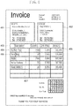
- Fig. 3 illustrates an example of a scan image. There is a case where this scan image is to be edited.
- Japanese Patent Application Laid-Open No. 2001-094760 discusses a function of editing a scan image. Pages '09 User Guide describes an application for creating and editing a document.
- Document US 2003/0123727 describes a table recognition apparatus.
- US2011/002547 discloses a technique of discriminating a table region from an input image and generating a workbook document for that table.
- a table region formed of a plurality of ruled lines in the scan image is identified, and character recognition is performed on characters inside the table region.
- the each ruled line forming the table region is further vectorized.
- the scan image is displayed in the left-side window, and a vectorization result and recognized characters are displayed in the right-side window ( Fig. 5 in Japanese Patent Application Laid-Open No. 2001-094760 ).
- the identified table region is deleted from the left-side window.
- a table to which edited characters are added is generated, and then the generated table is displayed on the left-side window.
- an information processing apparatus as specified in claims 1 to 5.
- a computer program comprising instructions for causing a computer to function as specified in clams 11.
- a computer-readable storage medium storing a program for causing a computer to function as specified in clams 12.
- Original characters refer to character images in a scan image.
- Recognized characters refer to characters corresponding to character codes (character recognition result) acquired by performing character recognition (optical character recognition (OCR) processing) on original characters, or characters corresponding to the relevant character codes displayed in an editing window. These recognized characters are displayed on the editing window (on an editing region) having an editing window text size (the editing window text size means a text size set for the editing window). Recognized cells refer to bounded areas identified by performing image processing on a scanned image.
- Editing a text refers to a user's action to delete the recognized characters from the editing window and then input substitutional characters in the editing window.
- a post-edit text refers to input substitutional characters or character codes corresponding to the relevant characters.
- the post-edit text is displayed with the editing window text size.
- the post-edit text is displayed with a scan image text size.
- Default values for both the editing window text size and the scan image text size are prestored in a storage unit 202.
- Fig. 1 illustrates a configuration of a copying machine 100 according to a first exemplary embodiment.
- the copying machine 100 includes a scanner 101, a transmitting and receiving unit 102, and a printer 103.
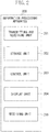
- Fig. 2 illustrates a configuration of an information processing apparatus 200 according to the present exemplary embodiment.
- the information processing apparatus 200 includes a central processing unit (CPU), a read only memory (ROM), and a random access memory (RAM).
- the CPU loads a program of the information processing apparatus 200 from the ROM and executes the program of the information processing apparatus 200 by using the RAM as a temporary storage area. Processing of each of units 201 to 205 is implemented by the above-described operation.
- a receiving unit 205 generally includes a keyboard and a mouse, but the present invention is not limited to this configuration. Further, the receiving unit 205 and the display unit 204 may be integrally configured. In this case, the receiving unit 205 and the display unit 204 are collectively referred to as a touch panel, and, in the following exemplary embodiments, a description of a click will be replaced with a description of a touch.
- a scan image (also referred to as scan image data or a document image) is generated.
- the transmitting and receiving unit 102 transmits the generated scan image to the information processing apparatus 200.
- the transmitting and receiving unit 201 of the information processing apparatus 200 stores the scan image in the storage unit 202.
- a user selects a scan image out of a plurality of scan images stored in the storage unit 202, via the receiving unit 205. Then, a control unit 203 displays the scan image on the display unit 204.
- the user issues an instruction to analyze the scan image displayed on the display unit 204, via the receiving unit 205. Then, the control unit 203 executes three pieces of processing: region division, character recognition, and cell recognition frame display, and displays an execution result on the display unit 204.
- Fig. 3 illustrates an example of a scan image.
- Fig. 4 illustrates a display result on the display unit 204 after the control unit 203 has executed the three pieces of processing.
- control unit 203 detects two circumscribed rectangles of which the value of distance therebetween is equal to or smaller than a predetermined threshold value, the control unit 203 unifies the two detected circumscribed rectangles into one. More specifically, the control unit 203 sets a new circumscribed rectangle which circumscribes the two circumscribed rectangles and, instead, deletes the two original circumscribed rectangles before unification.
- control unit 203 After setting a new circumscribed rectangle and deleting the two original circumscribed rectangles, the control unit 203 selects again circumscribed rectangles one by one from the beginning in the recognized cell, and unifies two circumscribed rectangles of which the value of distance therebetween is equal to or smaller than the third threshold value into one. More specifically, the control unit 203 repeats the processing for unifying circumscribed rectangles until there remain no circumscribed rectangles of which the value of distance therebetween is equal to or smaller than the third threshold value.
- circumscribed rectangles of black pixel clusters existing in one recognized cell are unified into one, but circumscribed rectangles across different recognized cells are not unified.
- Circumscribed rectangles set after the above-described processing are referred to as text regions.
- the above-described processing is referred to as identification of text regions in a recognized cell.
- the control unit 203 associates the positions of text regions existing in each recognized cell with the relevant recognized cell, and stores the relevant positions in the storage unit 202.
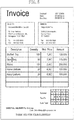
- Fig. 4 illustrates a result of region division performed on the scan image illustrated in Fig. 3 .
- the control unit 203 applies a four thick-line frame to the four sides of each identified recognized cell and applies a dotted line frame to the four sides of each text region.
- thick-line frames 402, 403, 404, 406, and 407 indicate recognized cells.
- Dotted line frames 401 and 405 indicate text regions.
- ruled lines in the thick-line frame 403 are blurred, and therefore the thick-line frame 403 which is essentially formed of a plurality of cells is identified as one recognized cell. Further, although the thick-line frames 406 and 407 essentially form one cell, they are identified as separate recognized cells because of noise.
- the control unit 203 performs character recognition processing on each text region to acquire recognized characters corresponding to the relevant text region.
- the control unit 203 associates the recognized characters with corresponding text regions and then stores the recognized characters in the storage unit 202.
- recognized characters are also associated with each recognized cell which has been associated with text regions in advance. If the control unit 203 does not perform character recognition or if character recognition fails, there is no recognized character to be associated with a text region.
- the control unit 203 applies a thick-line frame to ruled lines (four sides) forming each recognized cell and then displays the scan image on the display unit 204.
- a displayed screen is illustrated in Fig. 5 . Since each recognized cell is formed of four ruled lines, a thick-line frame is also formed of four lines. Although the frame lines may be neither thick lines nor solid lines and the frame color may not be black, the following descriptions will be made on the premise that frame lines are thick lines.
- the scan image displayed together with thick-line frames in processing (7) is a scan image before processing (1) to (6) is performed, i.e., a scan image before binarization.
- a click refers to an action to press the left mouse button and then release the button immediately (within a predetermined period of time).
- the control unit 203 determines that the relevant recognized cell is selected. The following descriptions will be made on the premise that a recognized cell 602 is selected.
- a mouse pointer 601 indicates a position pointed by the user via the receiving unit 205.
- step S802 when the above-described determination is made, the control unit 203 additionally displays on the display unit 204 an editing window (editing region) 604 for editing original characters inside the selected recognized cell and handles 603 for changing the position and size of the selected recognized cell 602.
- the handles 603 (referred to as recognized cell position change handles) are additionally displayed at the four corners of the thick-line frame of the selected recognized cell 602.
- Fig. 6 illustrates a state where the recognized cell position change handles 603 and the editing window 604 are additionally displayed.
- step S802 it is also desirable to make an arrangement so that the selected recognized cell (a recognized cell in the selection state) is distinguishable from other ones.
- a thicker line frame or extra thick-line frame
- other methods are applicable as long as the selected recognized cell is distinguishable from other ones.
- a method for using other colors or using dotted lines for the frame of the selected recognized cell is also considered.
- descriptions will be continued based on a case where a method for using a extra thick-line frame is applied as a method for distinguishing the selected recognized cell from other ones.
- a text entry box 605 in the editing window 604 displays the recognized characters associated with the selected recognized cell, in the editing window text size.
- the user is able to delete the recognized characters from the text entry box 605 and, instead, input other characters.
- the recognized characters can be edited.
- the text entry box 605 is empty.
- An OK button 606 is clicked to confirm the contents of text editing.
- An Apply button 607 is clicked to display the post-edit text on the scan image.
- a Cancel button 608 is clicked to cancel the contents of text editing.
- step S803 i.e., step S901 illustrated in Fig. 9
- step S804 i.e., step S1001 illustrated in Fig. 10
- step S901 the control unit 203 hides the recognized cell position change handles 603.
- step S902 the control unit 203 displays on the editing window 604 the characters edited thereon in the editing window text size.
- step S903 the control unit 203 determines whether the operation performed by the user on the receiving unit 205 after text editing is a selection of another recognized cell, a click of the Apply button, a click of the OK button, or a click of the Cancel button.
- the control unit 203 determines that the operation is a click of the Cancel button (Cancel in step S903), the control unit 203 cancels the selection state of the selected recognized cell. Then, the processing exits the flowchart illustrated in Fig. 9 .
- the recognized cell the selection state of which is canceled returns from the extra thick-line frame state to the thick-line frame state similar to other recognized cell as described above.
- step S904 the control unit 203 deletes all colors of the inside the selected recognized cell (i.e., inside the recognized cell in the scan image). More specifically, the inside of the recognized cell is filled in white. Although, in the example described below, the color of the inside the recognized cell is replaced with white color assuming that the cell color is white, the relevant color may be replaced with the background color if the background color of the cell is another color.
- step S905.1 the control unit 203 arranges the post-edit text in the scan image text size inside the recognized cell. Details will be described below with reference to Fig. 11 .
- step S905.2 the control unit 203 stores the post-edit scan image (i.e., an image after deleting inside the recognized cell and arranging the post-edit text) in the storage unit 202 and replaces the scan image displayed on the display unit 204 with the post-edit scan image.
- the post-edit scan image is displayed with a thick-line frame applied to the four sides of each recognized cell. Further, the four sides of the currently selected recognized cell remain displayed in the extra thick-line frame state.
- step S906 when the above-described operation is a click of the OK button (OK in step S906), the control unit 203 cancels the selection state of the selected recognized cell. Then, the processing exits the flowchart illustrated in Fig. 9 .
- the control unit 203 cancels the selection state of the selected recognized cell. Then, the processing proceeds to step S802.
- the above-described operation is a click of the Apply button 607 (Apply in step S906), then in step S907, the control unit 203 displays the text position change handles at the four corners of the circumscribed rectangle of the post-edit text arranged in step S905.1.
- step S908 the image after the text position change operation is stored and displayed as the post-edit scan image.
- the processing in step S908 is skipped.
- the user selects another recognized cell, clicks the OK button, or clicks the Cancel button.
- the control unit 203 cancels the selection state of the selected recognized cell. Then, the processing proceeds to step S802.
- the receiving unit 205 receives a click of the OK button (OK in step S909)
- the control unit 203 cancels the selection state of the selected recognized cell. Then, the processing exits the flowchart illustrated in Fig. 9 .
- step S910 the control unit 203 returns the inside of the selected recognized cell to the former state. More specifically, the control unit 203 returns the recognized cell to the state before the deletion processing in step S904. Then, the control unit 203 cancels the selection state of the selected recognized cell. Then, the processing exits the flowchart illustrated in Fig. 9 .
- the control unit 203 waits until the user selects another recognized cell.
- the control unit 203 cancels the selection waiting state.
- the control unit 203 instructs the transmitting and receiving unit 201 to transmit the post-edit scan image stored in the storage unit 202 to the other apparatus.
- the copying machine 100 receives the post-edit scan image via the transmitting and receiving unit 102 and, depending on an instruction from the user, prints the post-edit scan image via the printer 103.
- the post-edit scan image to be transmitted to another apparatus is an image having been subjected to the deletion of the inside of the (selected) recognized cell and the arrangement of the post-edit text.
- the image to be transmitted is not necessarily limited thereto.
- a file including the original scan image (the scan image before binarization), an instruction for deleting the inside the recognized cell, and an instruction for arranging the post-edit text may be transmitted.
- the other apparatus deletes the inside the recognized cell and arranges the post-edit text based on the original scan image.
- step S804 i.e., step S1001 illustrated in Fig. 10 .
- step S1001 the control unit 203 changes the position of the recognized cell according to the relevant operation, changes the four sides of the recognized cell at the position after change to the extra thick-line frame state, and displays the recognized cell on the display unit 204.
- the extra thick-line frame state of the four sides of the recognized cell at the position before change is canceled, and the cell returns to the normal state (a state where neither the thick-line frame nor the extra thick-line frame is applied).
- the recognized cell position change handles 603 are canceled from the corners of the recognized cell at the position before change, and displayed at the corners of the recognized cell at the position after change.
- control unit 203 waits until text editing is performed via the editing window 604.
- text editing is performed, the processing proceeds to step S901.
- the position of the recognized cell is made changeable in this way before performing text editing, the position of the recognized cell the inside of which is to be deleted in step S904 can be changed. Thus, the portion which should be deleted is deleted and the portion which should not be deleted is not deleted.
- step S905.1 The processing in step S905.1 will be described in detail below with reference to Fig. 11 .
- step S1101 the control unit 203 acquires the position of the selected recognized cell and the positions of text regions associated with the relevant recognized cell from the storage unit 202.
- step S1102 the control unit 203 sets a reference line.
- a recognized cell has upper left corner coordinates (X1, Y1) and lower right corner coordinates (X2, Y2), and a text region has upper left corner coordinates (x1, y1) and lower right corner coordinates (x2, y2).
- the control unit 203 calculates the right and left margins of the text region in the selected recognized cell.
- the left margin is (x1 - X1)
- the right margin is (X2 - x2).
- (Left margin) ⁇ (Right margin) the control unit 203 sets the reference line to the right side (right frame) of the text region, i.e., a straight line connecting the corners (x2, y1) and (x2, y2).
- (Left margin) ⁇ (Right margin) the control unit 203 sets the reference line to the left side (left frame) of the text region, i.e., a straight line connecting the corners (x1, y1) and (x1, y2).
- step S1103 the control unit 203 arranges the post-edit text according to the reference line set inside the selected recognized cell. More specifically, when the reference line is set to the left side of the text region, the post-edit text is arranged left-justified setting the reference line as a starting point. On the other hand, when the reference line is set to the right side of the text region, the post-edit text is arranged right-justified setting the reference line as a starting point.
- a text size determined in the following way may also be used.
- the text size is estimated to be 25 dots per character.
- the text size of the post-edit text is also approximately 25 dots per character. This enables calculating the number of points leading to a standard text size of 25 dots, and using the number of points as the size of the text to be arranged.
- the text size determined in this way may be manually changed by the user.
- the color, font, and style (standard, italic, or bold) of the text to be arranged may be manually changed by the user.
- the circumscribed rectangle of the post-edit text is H in height and W in width
- the text region has upper left corner coordinates (x1, y1) and lower right corner coordinates (x2, y2)
- the reference line acquired in step S1102 is set to the right side of the text region.
- the circumscribed rectangle of the post-edit text has upper left corner coordinates (x2 - W, y2 - H) and lower right corner coordinates (x2, y2).
- the circumscribed rectangle of the post-edit text When the reference line is set to the left side, the left side of the circumscribed rectangle of the post-edit text is aligned with the reference line (the left side of the text region). Therefore, the circumscribed rectangle of the post-edit text has upper left corner coordinates (x1, y2 - H) and lower right corner coordinates (x1 + W, y2).
- the position of the post-edit text in the height direction is based on the position of the lower side of the text region where the original characters were arranged.
- the position of the post-edit text may be determined so as to cause the vertical center of the post-edit text to coincide with the vertical center of the text region where the original characters were arranged.
- step S908 in the first exemplary embodiment in a case where the recognized cell is small or if the display magnification is small because a tablet type PC is used, moving the post-edit text is difficult, and therefore the text may not suitably fit into the recognized cell.
- Fig. 12 illustrates a method for easily moving the post-edit text even in such a case.
- step S1201 the control unit 203 determines whether the position of the post-edit text has been changed.
- the processing proceeds to step S1202.
- the processing proceeds to step S909.
- step S1202 the control unit 203 determines whether the position of the post-edit text exceeds the boundary of the recognized cell. In other words, the control unit 203 determines whether the post-edit text protrudes from the recognized cell.
- the processing proceeds to step S1203.
- the processing proceeds to step S909.
- the recognized cell has upper left corner coordinates (X1, Y1) and lower right corner coordinates (X2, Y2)
- the post-edit text after movement has upper left corner coordinates (x1, y1) and lower right corner coordinates (x2, y2).
- control unit 203 determines that the position of the post-edit text exceeds the boundary of the recognized cell.
- step S1203 the control unit 203 restores the post-edit text inside the recognized cell.
- the post-edit text is moved back inside the recognized cell by a predetermined distance T.
- the coordinates of the post-edit text are as follows.
- the post-edit text When the post-edit position exceeds the boundary on the right side, the post-edit text has lower right corner coordinates (X2 - T, y2). In this case, the post-edit text is moved to the left by (x2 - (X2 - T)). Therefore, the post-edit text has upper left corner coordinates (x1 - (x2 - (X2 - T)), y1).
- the post-edit text When the post-edit position exceeds the boundary on the left side, the post-edit text has upper left corner coordinates (X1 + T, y1). In this case, the post-edit text is moved to the right by (X1 + T - x1). Therefore, the post-edit text has lower right corner coordinates (x2 + (X1 + T - x1), y2).
- the post-edit text When the post-edit position exceeds the boundary on the lower side, the post-edit text has lower right corner coordinates (x2, Y2 - T). In this case, the post-edit text is moved upward by (y2 - (Y2 - T)). Therefore, the post-edit text has upper left corner coordinates (x1, y1 - (y2 - (Y2 - T))).
- the post-edit text When the post-edit position exceeds the boundary on the upper side, the post-edit text has upper left corner coordinates (x1, Y1 + T). In this case, the post-edit text is moved downward by (Y1 + T - y1). Therefore, the post-edit text has lower right corner coordinates (x2, y2 + (Y1 + T - y1)).
- step S1102 in the first exemplary embodiment in a table having no ruled lines as in the example illustrated in Fig. 13 , the recognized cell cannot be determined based on ruled line positions, and therefore margins between the recognized cell and a text region cannot be calculated. Processing performed by the control unit 203 to easily set a reference line even in such a case will be described below with reference to the flowchart illustrated in Fig. 15 .
- step S1501 the control unit 203 determines whether the editing target text belongs to a table.
- the text in the recognized cell 602 illustrated in Fig. 6 belongs to a table.
- a table having no ruled lines as illustrated in Fig. 13 cannot be recognized as a table. Therefore, the control unit 203 determines that the text does not belong to a table.
- step S1501 When the editing target text belongs to a table (YES in step S1501), the processing proceeds to step S1502. On the other hand, when the editing target text does not belong to a table (NO in step S1501), the processing proceeds to step S1506.
- the description when the editing target text belongs to a table is similar to that in the first exemplary embodiment.
- step S1502 the control unit 203 acquires margins between the recognized cell and a text region.
- step S1503 the control unit 203 compares the width of the left margin with the width of the right margin to determine whether the left margin is equal to or greater than the right margin, i.e., whether a condition "(Left margin) ⁇ (Right margin)" is satisfied.
- the processing proceeds to step S1504.
- the processing proceeds to step S1505.
- step S1504 the control unit 203 sets the reference line to the right side of the text region of the editing target text.
- step S1505 the control unit 203 sets the reference line to the left side of the text region of the editing target text.
- step S1506 the control unit 203 checks all of text regions, and acquires the text region of which the difference between the X-coordinate of the right side of the editing target text region and the X-coordinate of the right side of each text region located upper and lower side thereof is a threshold value or below, and the smallest.
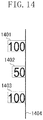
- Fig. 14 illustrates an editing target text region 1402 and text regions 1401 and 1403 respectively existing on the upper and lower sides of the editing target text region 1402.
- step S1506 the difference between the X-coordinate of the right side of the text region 1402 and the X-coordinate of the right side of each of the text regions 1401 and 1403 is 0. Therefore, each of the text regions 1401 and 1403 is determined as a text region of which difference between the X-coordinate of the right side and the X-coordinate of the right side of the text region 1402 is a threshold value (for example, 10 pixels) or below, and the difference thereof is the smallest.
- a threshold value for example, 10 pixels
- step S1507 the control unit 203 compares the X-coordinate of the left side of the editing target text region with the X-coordinate of the left side of each of the upper and lower text regions, and acquires the text region of which the difference therebetween is a threshold value or below, and the smallest.
- the difference between the X-coordinate of the left side of the editing target text region 1402 and the X-coordinate of the left side of each of the text regions 1401 and 1403 is larger than the threshold value (10 pixels), and therefore no text region is acquired.
- step S1508 the control unit 203 compares the difference between the X-coordinates of the right sides of the upper or the lower text region and the editing target text region acquired in step S1506 with the difference between the X-coordinates of the left sides of the relevant text regions acquired in step S1507. More specifically, the control unit 203 determines whether the difference between the X-coordinates of the left sides is equal to or greater than the difference between the X-coordinates of the right sides, i.e., whether a condition "(Difference between left sides) ⁇ (Difference between right sides)" is satisfied.
- step S1504 the control unit 203 sets the reference line to the right side of the editing target text region 1402.
- step S1505 the control unit 203 sets the reference line to the left side of the editing target text region 1402.
- step S1506 text regions satisfying the condition can be acquired in step S1506, and such text regions cannot be acquired in step S1507. If no text region is acquired, the control unit 203 determines that the condition "(Difference between left sides) ⁇ (Difference between right sides)" is satisfied on the assumption that the difference is infinite. In this case, "Infinite ⁇ 0" is true and therefore the condition is satisfied. Then, the processing proceeds to step S1504. In step S1504, the control unit 203 determines to set the reference line to the right side of the text region. A line segment 1404 illustrated in Fig. 14 explicitly indicates that the reference line is set to the right side of the text region 1402.
- step S1102. This completes the processing for setting a reference line in step S1102. Then, the processing proceeds to step S1103.
- the post-edit text is arranged.
- the text size of the post-edit text is preset by the user.
- the control unit 203 sets the text size of the post-edit text through an estimation based on the original character image.
- An example of a size estimation method has been described in the first exemplary embodiment. However, since the preset size and the size acquired through an estimation are not necessarily correct, changing the text size is sometimes required. Processing performed by the control unit 203 to easily change the text size even in such a case will be described below with reference to Fig. 7 .
- Fig. 7 illustrates an arrangement of the post-edit text.
- a numerical value 701 is input in the text entry box 605 illustrated in Fig. 7 with respect to the recognized cell 602 illustrated in Fig. 6 .
- the former numerical value is 120,000 and a replacing numerical value 701 is 300,000.
- step S1103 When the user inputs a numerical value in the text entry box 605 and then presses the Apply button 607, in step S1103, the control unit 203 generates a replacing text 702 using a preset size or an estimated size for the replacing numerical value 701. Then, the control unit 203 arranges the replacing text 702 based on the reference line acquired in step S1102.
- step S907 the control unit 203 displays text position change handles 703.
- the processing for changing the text position in step S908 has been described, a method for changing the text size of the replacing text 702 will be described below.
- Dragging one of the text position change handles 703 to enlarge the text region 1402 is referred to as text size enlargement, and dragging one of the text position change handles 703 to reduce the text region 1402 is referred to as text size reduction.
- a method for acquiring the text size will be described below.
- the text region before change is assumed to be HI in height and W1 in width.
- the text region after change is assumed to be H2 in height and W2 in width.
- Text size after change Text size before change ⁇ Final change magnification .
- the smaller change magnification is set as the final change magnification because, if the larger change magnification is set as the final change magnification, the text does not fit into the height or width of the text region.
- the text size of the post-edit text can easily be changed in this way.
- control unit 203 regenerates the replacing text 702 according to the changed text size, and then displays the replacing text 702 based on the reference line acquired in step S1102.
- a fifth exemplary embodiment will be described below.
- a method for changing the text size of the post-edit text performed by the control unit 203 in step S1103 has been described.
- a small display area such as a display screen of a tablet PC
- an example of a method for changing the text size used in such a case will be described below. Instead of handle operations, click and tap operations are used in the present exemplary embodiment.
- Double-clicking the inside of the text region 1402 enlarges the text size in one step.
- double-clicking the inside thereof reduces the text size in one step.
- the text size is further reduced and becomes a predetermined text size or below, the text size returns to the former one.
- One step in text size may mean units of 1 point or units of 2 points.
- the former text size is 12 points
- the minimum size is 8 point
- the 1-step change size is 2 points
- the text size changes in the following order each time double-clicking is made: 12, 14, 16, 18 (recognized cell region exceeded), 16, 14, 12, 10, 8 (minimum setting value), and 12 (original value).
- the method for changing the text size may be in such a way that a single-click (tap) enlarges the text size in one step and a double-click reduces the text size in one step.
- the method may also be in such a way that a left-click enlarges the text size and a right-click reduces the text size.
- Embodiments of the present invention can also be realized by a computer of a system or apparatus that reads out and executes computer executable instructions (e.g., one or more programs) recorded on a storage medium (which may also be referred to more fully as a 'non-transitory computer-readable storage medium') to perform the functions of one or more of the above-described embodiments and/or that includes one or more circuits (e.g., application specific integrated circuit (ASIC)) for performing the functions of one or more of the above-described embodiments, and by a method performed by the computer of the system or apparatus by, for example, reading out and executing the computer executable instructions from the storage medium to perform the functions of one or more of the above-described embodiments and/or controlling the one or more circuits to perform the functions of one or more of the above-described embodiments.
- ASIC application specific integrated circuit
- the computer may comprise one or more processors (e.g., central processing unit (CPU), micro processing unit (MPU)) and may include a network of separate computers or separate processors to read out and execute the computer executable instructions.
- the computer executable instructions may be provided to the computer, for example, from a network or the storage medium.
- the storage medium may include, for example, one or more of a hard disk, a random-access memory (RAM), a read only memory (ROM), a storage of distributed computing systems, an optical disk (such as a compact disc (CD), digital versatile disc (DVD), or Blu-ray Disc (BD)TM), a flash memory device, a memory card, and the like.
Description
- The present invention relates to an information processing apparatus for editing a table region in an image.
-
Fig. 3 illustrates an example of a scan image. There is a case where this scan image is to be edited. Japanese Patent Application Laid-Open No.2001-094760 US 2003/0123727 describes a table recognition apparatus.US2011/002547 discloses a technique of discriminating a table region from an input image and generating a workbook document for that table. - More specifically, with the function discussed in Japanese Patent Application Laid-Open No.
2001-094760 Fig. 5 in Japanese Patent Application Laid-Open No.2001-094760 - In a technique discussed in Japanese Patent Application Laid-Open No.
2001-094760 - According to a first aspect of the present invention, there is provided an information processing apparatus as specified in
claims 1 to 5. According to a second aspect of the present invention, there is provided a method for controlling an information processing apparatus as specified in clams 6 to 10. According to a third aspect of the present invention, there is provided a computer program comprising instructions for causing a computer to function as specified in clams 11. According to a fourth aspect of the present invention, there is provided a computer-readable storage medium storing a program for causing a computer to function as specified in clams 12. - Further features of the present invention will become apparent from the following description of exemplary embodiments with reference to the attached drawings.
-
-
Fig. 1 is a block diagram illustrating a configuration of a copying machine. -
Fig. 2 is a block diagram illustrating a configuration of an information processing apparatus. -
Fig. 3 is an example of a scan image. -
Fig. 4 illustrates a result of region division on the scan image. -
Fig. 5 illustrates a display screen for displaying frames of recognized cells. -
Fig. 6 illustrates a display screen displayed when a recognized cell is selected. -
Fig. 7 illustrates a screen displaying a post-edit text. -
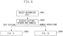
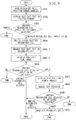
Fig. 8 is a flowchart illustrating main processing. -
Fig. 9 is a flowchart illustrating editing processing. -
Fig. 10 is a flowchart illustrating processing for changing the position of the recognized cell. -
Fig. 11 is a flowchart illustrating processing for displaying the post-edit text. -
Fig. 12 is a flowchart illustrating processing for changing the position of the post-edit text. -
Fig. 13 illustrates another example of a scan image. -
Fig. 14 is a supplementary view illustrating a method for determining a reference line. -
Fig. 15 is a flowchart according to a third exemplary embodiment. - First of all, terms will be defined below.
- Original characters refer to character images in a scan image.
- Recognized characters refer to characters corresponding to character codes (character recognition result) acquired by performing character recognition (optical character recognition (OCR) processing) on original characters, or characters corresponding to the relevant character codes displayed in an editing window. These recognized characters are displayed on the editing window (on an editing region) having an editing window text size (the editing window text size means a text size set for the editing window). Recognized cells refer to bounded areas identified by performing image processing on a scanned image.
- "Editing a text" refers to a user's action to delete the recognized characters from the editing window and then input substitutional characters in the editing window. "A post-edit text" refers to input substitutional characters or character codes corresponding to the relevant characters. When displayed on the editing window, the post-edit text is displayed with the editing window text size. When displayed on the scan image, the post-edit text is displayed with a scan image text size.
- Default values for both the editing window text size and the scan image text size are prestored in a
storage unit 202. - An exemplary embodiment for embodying the present invention will be described below with reference to the accompanying drawings.
-
Fig. 1 illustrates a configuration of acopying machine 100 according to a first exemplary embodiment. Thecopying machine 100 includes ascanner 101, a transmitting and receivingunit 102, and aprinter 103. -
Fig. 2 illustrates a configuration of aninformation processing apparatus 200 according to the present exemplary embodiment. Theinformation processing apparatus 200 includes a central processing unit (CPU), a read only memory (ROM), and a random access memory (RAM). The CPU loads a program of theinformation processing apparatus 200 from the ROM and executes the program of theinformation processing apparatus 200 by using the RAM as a temporary storage area. Processing of each ofunits 201 to 205 is implemented by the above-described operation. A receivingunit 205 generally includes a keyboard and a mouse, but the present invention is not limited to this configuration. Further, thereceiving unit 205 and thedisplay unit 204 may be integrally configured. In this case, thereceiving unit 205 and thedisplay unit 204 are collectively referred to as a touch panel, and, in the following exemplary embodiments, a description of a click will be replaced with a description of a touch. - When the
scanner 101 of thecopying machine 100 scans a document, a scan image (also referred to as scan image data or a document image) is generated. The transmitting and receivingunit 102 transmits the generated scan image to theinformation processing apparatus 200. Upon reception of the scan image, the transmitting and receivingunit 201 of theinformation processing apparatus 200 stores the scan image in thestorage unit 202. - A user selects a scan image out of a plurality of scan images stored in the
storage unit 202, via thereceiving unit 205. Then, acontrol unit 203 displays the scan image on thedisplay unit 204. - The user issues an instruction to analyze the scan image displayed on the
display unit 204, via the receivingunit 205. Then, thecontrol unit 203 executes three pieces of processing: region division, character recognition, and cell recognition frame display, and displays an execution result on thedisplay unit 204.Fig. 3 illustrates an example of a scan image.Fig. 4 illustrates a display result on thedisplay unit 204 after thecontrol unit 203 has executed the three pieces of processing. -
- (1) The
control unit 203 performs binarization on the scan image to acquire a binary image. As a result of the binarization, a pixel having a brightness value lower than a threshold value in the scan image is a black pixel, and a pixel having a brightness value higher than the threshold value is a white pixel. Although the following descriptions will be made on the premise that the resolution of the scan image is 100 dot per inch (DPI), the scan image is not limited to this resolution. - (2) For the binary image, the
control unit 203 tracks the contour of black pixels connected on a 8-connection basis to detect a block of black pixels (black pixel cluster) continuously existing in one of the eight directions. The 8-connection means that pixels of an identical color (black pixels in this case) continuously exist in any one of the eight directions (upper left, left, lower left, below, lower right, right, upper right, and above). On the other hand, the 4-connection means that pixels of an identical color continuously exist in any one of the four directions (left, below, right, and above). In processing (2), an independent black pixel (isolated point) of which all of eight adjacent pixels existing in the eight directions are non-black pixels is recognized as noise, and is not detected. On the other hand, a black pixel of which at least one of eight adjacent pixels existing in the eight directions is a black pixel is detected as a black pixel cluster together with the adjacent black pixel(s). - (3) The
control unit 203 detects, out of detected black pixel clusters, a black pixel cluster having length longer than a first threshold length (e.g., 50 pixels = 1.25 cm) and having width narrower than a second threshold length (e.g., 10 pixels = 0.25 cm). The detected black pixel cluster is referred to as a ruled line.
Before determining a ruled line, table region determination may be performed. For example, targeting the black pixel cluster having a size equal to or larger than a predetermined size (minimum size of a presumed table) detected in processing (2), thecontrol unit 203 tracks the contour of white pixels inside the relevant black pixel cluster to detect a plurality of white pixel clusters. Then, thecontrol unit 203 determines whether circumscribed rectangles of a plurality of the white pixel clusters are arranged in a lattice pattern to determine whether the relevant black pixel cluster is a table region. Then, thecontrol unit 203 detects ruled lines from the inside of the table region. - (4) The
control unit 203 identifies a region which is surrounded by four ruled lines and does not include any other ruled lines. The identified region is referred to as a recognized cell. Further, processing (4) is referred to as recognized cell identification. Thecontrol unit 203 stores the position of the identified recognized cell in thestorage unit 202.
The method for identifying a recognized cell is not limited to the above-described one. For example, it is also possible to track the contour of white pixels inside a table region to detect a white pixel cluster, and identify the circumscribed rectangle of each white pixel cluster having a size equal to or larger than a predetermined size (minimum size of a presumed cell) as a recognized cell. - (5) The
control unit 203 determines whether a black pixel cluster exists in each recognized cell. When thecontrol unit 203 determines that a black pixel cluster exists in each recognized cell, thecontrol unit 203 sets circumscribed rectangles to all of black pixel clusters existing in each recognized cell. - Further, when a plurality of circumscribed rectangles is set in one recognized cell, the
control unit 203 determines whether a value of distance between the circumscribed rectangles is equal to or smaller than a third threshold value (for example, 20 pixels = 0.5 cm). More specifically, thecontrol unit 203 selects circumscribed rectangles one by one, and detects a circumscribed rectangle of which the value of distance from the selected circumscribed rectangle is equal to or smaller than the third threshold value. - Further, when the
control unit 203 detects two circumscribed rectangles of which the value of distance therebetween is equal to or smaller than a predetermined threshold value, thecontrol unit 203 unifies the two detected circumscribed rectangles into one. More specifically, thecontrol unit 203 sets a new circumscribed rectangle which circumscribes the two circumscribed rectangles and, instead, deletes the two original circumscribed rectangles before unification. - After setting a new circumscribed rectangle and deleting the two original circumscribed rectangles, the
control unit 203 selects again circumscribed rectangles one by one from the beginning in the recognized cell, and unifies two circumscribed rectangles of which the value of distance therebetween is equal to or smaller than the third threshold value into one. More specifically, thecontrol unit 203 repeats the processing for unifying circumscribed rectangles until there remain no circumscribed rectangles of which the value of distance therebetween is equal to or smaller than the third threshold value. - In the present exemplary embodiment, circumscribed rectangles of black pixel clusters existing in one recognized cell are unified into one, but circumscribed rectangles across different recognized cells are not unified.
- Circumscribed rectangles set after the above-described processing (i.e., a circumscribed rectangle after the relevant unification processing) are referred to as text regions. The above-described processing is referred to as identification of text regions in a recognized cell. The
control unit 203 associates the positions of text regions existing in each recognized cell with the relevant recognized cell, and stores the relevant positions in thestorage unit 202. -
Fig. 4 illustrates a result of region division performed on the scan image illustrated inFig. 3 . Referring toFig. 4 , thecontrol unit 203 applies a four thick-line frame to the four sides of each identified recognized cell and applies a dotted line frame to the four sides of each text region. In the example illustrated inFig. 4 , thick-line frames 402, 403, 404, 406, and 407 indicate recognized cells. Dotted line frames 401 and 405 indicate text regions. - Referring to
Fig. 4 , ruled lines in the thick-line frame 403 are blurred, and therefore the thick-line frame 403 which is essentially formed of a plurality of cells is identified as one recognized cell. Further, although the thick-line frames 406 and 407 essentially form one cell, they are identified as separate recognized cells because of noise. - (6) The
control unit 203 performs character recognition processing on each text region to acquire recognized characters corresponding to the relevant text region. Thecontrol unit 203 associates the recognized characters with corresponding text regions and then stores the recognized characters in thestorage unit 202. Thus, recognized characters are also associated with each recognized cell which has been associated with text regions in advance. If thecontrol unit 203 does not perform character recognition or if character recognition fails, there is no recognized character to be associated with a text region. - (7) The
control unit 203 applies a thick-line frame to ruled lines (four sides) forming each recognized cell and then displays the scan image on thedisplay unit 204. A displayed screen is illustrated inFig. 5 . Since each recognized cell is formed of four ruled lines, a thick-line frame is also formed of four lines. Although the frame lines may be neither thick lines nor solid lines and the frame color may not be black, the following descriptions will be made on the premise that frame lines are thick lines. The scan image displayed together with thick-line frames in processing (7) is a scan image before processing (1) to (6) is performed, i.e., a scan image before binarization. - The user clicks an arbitrary position inside the image (for example, inside the image illustrated in
Fig. 5 ) currently displayed on thedisplay unit 204 via the receivingunit 205. In the present specification, a click refers to an action to press the left mouse button and then release the button immediately (within a predetermined period of time). In step S801, when the clicked position is inside a region surrounded by four thick lines (i.e., inside a recognized cell), thecontrol unit 203 determines that the relevant recognized cell is selected. The following descriptions will be made on the premise that a recognizedcell 602 is selected. Amouse pointer 601 indicates a position pointed by the user via the receivingunit 205. - In step S802, when the above-described determination is made, the
control unit 203 additionally displays on thedisplay unit 204 an editing window (editing region) 604 for editing original characters inside the selected recognized cell and handles 603 for changing the position and size of the selected recognizedcell 602. The handles 603 (referred to as recognized cell position change handles) are additionally displayed at the four corners of the thick-line frame of the selected recognizedcell 602.Fig. 6 illustrates a state where the recognized cell position change handles 603 and theediting window 604 are additionally displayed. - As illustrated in
Fig. 6 , in step S802, it is also desirable to make an arrangement so that the selected recognized cell (a recognized cell in the selection state) is distinguishable from other ones. For example, it is also desirable to use a thicker line frame (or extra thick-line frame) for the selected recognized cell. Obviously, other methods are applicable as long as the selected recognized cell is distinguishable from other ones. For example, a method for using other colors or using dotted lines for the frame of the selected recognized cell is also considered. In the present specification, descriptions will be continued based on a case where a method for using a extra thick-line frame is applied as a method for distinguishing the selected recognized cell from other ones. - When the selection state of the recognized cell is canceled, such a extra thick-line frame state returns to the former state (i.e., returns to the thick-line frame state similar to other recognized cells).
- A
text entry box 605 in theediting window 604 displays the recognized characters associated with the selected recognized cell, in the editing window text size. The user is able to delete the recognized characters from thetext entry box 605 and, instead, input other characters. Thus, the recognized characters can be edited. - If there is no recognized character associated with the selected recognized cell (e.g., if no text region is detected from inside the selected recognized cell, or if a text region is detected and character recognition fails resulting in no recognized character), the
text entry box 605 is empty. - An
OK button 606 is clicked to confirm the contents of text editing. AnApply button 607 is clicked to display the post-edit text on the scan image. A Cancelbutton 608 is clicked to cancel the contents of text editing. - After the screen illustrated in
Fig. 6 is displayed, the user performs a new operation on the receivingunit 205. If the operation is text editing on theediting window 604, the processing proceeds to step S803 (i.e., step S901 illustrated inFig. 9 ). If the operation performed by the user on the receivingunit 205 is an operation of a recognized cell position change handle, the processing proceeds to step S804 (i.e., step S1001 illustrated inFig. 10 ). - In step S901, the
control unit 203 hides the recognized cell position change handles 603. - In step S902, the
control unit 203 displays on theediting window 604 the characters edited thereon in the editing window text size. - In step S903, the
control unit 203 determines whether the operation performed by the user on the receivingunit 205 after text editing is a selection of another recognized cell, a click of the Apply button, a click of the OK button, or a click of the Cancel button. When thecontrol unit 203 determines that the operation is a click of the Cancel button (Cancel in step S903), thecontrol unit 203 cancels the selection state of the selected recognized cell. Then, the processing exits the flowchart illustrated inFig. 9 . Although descriptions will be omitted, the recognized cell the selection state of which is canceled returns from the extra thick-line frame state to the thick-line frame state similar to other recognized cell as described above. - When the
control unit 203 determines that the operation is not a click of the Cancel button (Another Recognized Cell Selected, Apply, or OK in step S903), then in step S904, thecontrol unit 203 deletes all colors of the inside the selected recognized cell (i.e., inside the recognized cell in the scan image). More specifically, the inside of the recognized cell is filled in white. Although, in the example described below, the color of the inside the recognized cell is replaced with white color assuming that the cell color is white, the relevant color may be replaced with the background color if the background color of the cell is another color. - Thereafter, in step S905.1, the
control unit 203 arranges the post-edit text in the scan image text size inside the recognized cell. Details will be described below with reference toFig. 11 . In step S905.2, thecontrol unit 203 stores the post-edit scan image (i.e., an image after deleting inside the recognized cell and arranging the post-edit text) in thestorage unit 202 and replaces the scan image displayed on thedisplay unit 204 with the post-edit scan image. Thus, the post-edit scan image is displayed with a thick-line frame applied to the four sides of each recognized cell. Further, the four sides of the currently selected recognized cell remain displayed in the extra thick-line frame state. - Further, when the above-described operation is a click of the OK button (OK in step S906), the
control unit 203 cancels the selection state of the selected recognized cell. Then, the processing exits the flowchart illustrated inFig. 9 . When the above-described operation is a selection of another recognized cell (Another Recognized Cell Selected in step S906), thecontrol unit 203 cancels the selection state of the selected recognized cell. Then, the processing proceeds to step S802. When the above-described operation is a click of the Apply button 607 (Apply in step S906), then in step S907, thecontrol unit 203 displays the text position change handles at the four corners of the circumscribed rectangle of the post-edit text arranged in step S905.1. - If the user wants to change the position of the post-edit text, the user performs an operation for moving the position of a text position change handle on the receiving
unit 205. Then, thecontrol unit 203 performs a text position change operation according to the relevant operation, and further replaces the post-edit scan image stored in thestorage unit 202 with the image after the text position change operation. Thecontrol unit 203 also replaces the currently displayed post-edit scan image with the image after the text position change operation. In step S908, the image after the text position change operation is stored and displayed as the post-edit scan image. On the other hand, when it is not necessary to change the text position, no operation is performed on the text position change handles. In this case, the processing in step S908 is skipped. - Subsequently, the user selects another recognized cell, clicks the OK button, or clicks the Cancel button. When the receiving
unit 205 receives a selection of another recognized cell (Another Recognized Cell Selected in step S909), thecontrol unit 203 cancels the selection state of the selected recognized cell. Then, the processing proceeds to step S802. When the receivingunit 205 receives a click of the OK button (OK in step S909), thecontrol unit 203 cancels the selection state of the selected recognized cell. Then, the processing exits the flowchart illustrated inFig. 9 . When the receivingunit 205 receives a click of the Cancel button (Cancel in step S909), then in step S910, thecontrol unit 203 returns the inside of the selected recognized cell to the former state. More specifically, thecontrol unit 203 returns the recognized cell to the state before the deletion processing in step S904. Then, thecontrol unit 203 cancels the selection state of the selected recognized cell. Then, the processing exits the flowchart illustrated inFig. 9 . - After completing the processing illustrated in
Fig. 9 , thecontrol unit 203 waits until the user selects another recognized cell. When the user instructs the receivingunit 205 to transmit the post-edit scan image to another apparatus, thecontrol unit 203 cancels the selection waiting state. Then, thecontrol unit 203 instructs the transmitting and receivingunit 201 to transmit the post-edit scan image stored in thestorage unit 202 to the other apparatus. Assuming that the other apparatus is the copyingmachine 100, the copyingmachine 100 receives the post-edit scan image via the transmitting and receivingunit 102 and, depending on an instruction from the user, prints the post-edit scan image via theprinter 103. - Upon completion of the above-described processing, the post-edit scan image to be transmitted to another apparatus is an image having been subjected to the deletion of the inside of the (selected) recognized cell and the arrangement of the post-edit text. However, the image to be transmitted is not necessarily limited thereto. For example, a file including the original scan image (the scan image before binarization), an instruction for deleting the inside the recognized cell, and an instruction for arranging the post-edit text, may be transmitted. When another apparatus receives such a file, the other apparatus deletes the inside the recognized cell and arranges the post-edit text based on the original scan image.
- As described above, when the operation performed by the user on the receiving
unit 205 is an operation for the recognized cell position change handles 603, the processing proceeds to step S804 (i.e., step S1001 illustrated inFig. 10 ). - In step S1001, the
control unit 203 changes the position of the recognized cell according to the relevant operation, changes the four sides of the recognized cell at the position after change to the extra thick-line frame state, and displays the recognized cell on thedisplay unit 204. In this case, the extra thick-line frame state of the four sides of the recognized cell at the position before change is canceled, and the cell returns to the normal state (a state where neither the thick-line frame nor the extra thick-line frame is applied). Likewise, the recognized cell position change handles 603 are canceled from the corners of the recognized cell at the position before change, and displayed at the corners of the recognized cell at the position after change. - Subsequently, the
control unit 203 waits until text editing is performed via theediting window 604. When text editing is performed, the processing proceeds to step S901. - If the position of the recognized cell is made changeable in this way before performing text editing, the position of the recognized cell the inside of which is to be deleted in step S904 can be changed. Thus, the portion which should be deleted is deleted and the portion which should not be deleted is not deleted.
- The processing in step S905.1 will be described in detail below with reference to
Fig. 11 . - In step S1101, the
control unit 203 acquires the position of the selected recognized cell and the positions of text regions associated with the relevant recognized cell from thestorage unit 202. - In step S1102, the
control unit 203 sets a reference line. - It is assumed that a recognized cell has upper left corner coordinates (X1, Y1) and lower right corner coordinates (X2, Y2), and a text region has upper left corner coordinates (x1, y1) and lower right corner coordinates (x2, y2).
- To set a reference line, the
control unit 203 calculates the right and left margins of the text region in the selected recognized cell. In this case, the left margin is (x1 - X1), and the right margin is (X2 - x2). When (Left margin) ≥ (Right margin), thecontrol unit 203 sets the reference line to the right side (right frame) of the text region, i.e., a straight line connecting the corners (x2, y1) and (x2, y2). When (Left margin) < (Right margin), thecontrol unit 203 sets the reference line to the left side (left frame) of the text region, i.e., a straight line connecting the corners (x1, y1) and (x1, y2). - In step S1103, the
control unit 203 arranges the post-edit text according to the reference line set inside the selected recognized cell. More specifically, when the reference line is set to the left side of the text region, the post-edit text is arranged left-justified setting the reference line as a starting point. On the other hand, when the reference line is set to the right side of the text region, the post-edit text is arranged right-justified setting the reference line as a starting point. - Although, in this case, the default size of the scan image text is used as the size of the text to be arranged, a text size determined in the following way may also be used. For example, when the width of the original characters existing in the selected recognized cell is 100 dots per 4 characters, the text size is estimated to be 25 dots per character. To naturally arrange the post-edit text in the recognized cell, it is desirable that the text size of the post-edit text is also approximately 25 dots per character. This enables calculating the number of points leading to a standard text size of 25 dots, and using the number of points as the size of the text to be arranged. Further, the text size determined in this way may be manually changed by the user. Further, the color, font, and style (standard, italic, or bold) of the text to be arranged may be manually changed by the user.
- It is assumed that the circumscribed rectangle of the post-edit text is H in height and W in width, that the text region has upper left corner coordinates (x1, y1) and lower right corner coordinates (x2, y2), and that the reference line acquired in step S1102 is set to the right side of the text region.
- In Windows (registered trademark), the x-coordinate increases toward the right direction and the y-coordinate increases toward the downward direction. Therefore, in the above-described case, the circumscribed rectangle of the post-edit text has upper left corner coordinates (x2 - W, y2 - H) and lower right corner coordinates (x2, y2).
- When the reference line is set to the left side, the left side of the circumscribed rectangle of the post-edit text is aligned with the reference line (the left side of the text region). Therefore, the circumscribed rectangle of the post-edit text has upper left corner coordinates (x1, y2 - H) and lower right corner coordinates (x1 + W, y2).
- In the above-described examples, the position of the post-edit text in the height direction (Y direction) is based on the position of the lower side of the text region where the original characters were arranged. However, instead of this position, the position of the post-edit text may be determined so as to cause the vertical center of the post-edit text to coincide with the vertical center of the text region where the original characters were arranged.
- In step S908 in the first exemplary embodiment, in a case where the recognized cell is small or if the display magnification is small because a tablet type PC is used, moving the post-edit text is difficult, and therefore the text may not suitably fit into the recognized cell.
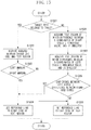
Fig. 12 illustrates a method for easily moving the post-edit text even in such a case. - In step S1201, the
control unit 203 determines whether the position of the post-edit text has been changed. When the position has been changed (YES in step S1201), the processing proceeds to step S1202. On the other hand, when the position has not been changed (NO in step S1201), the processing proceeds to step S909. - In step S1202, the
control unit 203 determines whether the position of the post-edit text exceeds the boundary of the recognized cell. In other words, thecontrol unit 203 determines whether the post-edit text protrudes from the recognized cell. When the post-edit text exceeds the boundary (YES in step S1202), the processing proceeds to step S1203. On the other hand, when the post-edit text does not exceeds the boundary (NO in step S1202), the processing proceeds to step S909. - It is assumed that the recognized cell has upper left corner coordinates (X1, Y1) and lower right corner coordinates (X2, Y2), and the post-edit text after movement has upper left corner coordinates (x1, y1) and lower right corner coordinates (x2, y2).
- In any one of the following cases, the
control unit 203 determines that the position of the post-edit text exceeds the boundary of the recognized cell. - <1> When the post-edit position exceeds the boundary on the right side (x2 > X2)
- <2> When the post-edit position exceeds the boundary on the left side (X1 > x1)
- <3> When the post-edit position exceeds the boundary on the lower side (y2 > Y2)
- <4> When the post-edit position exceeds the boundary on the upper side (Y1 > y1)
- In step S1203, the
control unit 203 restores the post-edit text inside the recognized cell. In the present exemplary embodiment, the post-edit text is moved back inside the recognized cell by a predetermined distance T. - After the post-edit text has been moved back inside the recognized cell by the distance T in cases <1> to <4>, the coordinates of the post-edit text are as follows.
- When the post-edit position exceeds the boundary on the right side, the post-edit text has lower right corner coordinates (X2 - T, y2). In this case, the post-edit text is moved to the left by (x2 - (X2 - T)). Therefore, the post-edit text has upper left corner coordinates (x1 - (x2 - (X2 - T)), y1).
- When the post-edit position exceeds the boundary on the left side, the post-edit text has upper left corner coordinates (X1 + T, y1). In this case, the post-edit text is moved to the right by (X1 + T - x1). Therefore, the post-edit text has lower right corner coordinates (x2 + (X1 + T - x1), y2).
- When the post-edit position exceeds the boundary on the lower side, the post-edit text has lower right corner coordinates (x2, Y2 - T). In this case, the post-edit text is moved upward by (y2 - (Y2 - T)). Therefore, the post-edit text has upper left corner coordinates (x1, y1 - (y2 - (Y2 - T))).
- When the post-edit position exceeds the boundary on the upper side, the post-edit text has upper left corner coordinates (x1, Y1 + T). In this case, the post-edit text is moved downward by (Y1 + T - y1). Therefore, the post-edit text has lower right corner coordinates (x2, y2 + (Y1 + T - y1)).
- A third exemplary embodiment will be described below. In step S1102 in the first exemplary embodiment, in a table having no ruled lines as in the example illustrated in
Fig. 13 , the recognized cell cannot be determined based on ruled line positions, and therefore margins between the recognized cell and a text region cannot be calculated. Processing performed by thecontrol unit 203 to easily set a reference line even in such a case will be described below with reference to the flowchart illustrated inFig. 15 . - In step S1501, the
control unit 203 determines whether the editing target text belongs to a table. The text in the recognizedcell 602 illustrated inFig. 6 belongs to a table. A table having no ruled lines as illustrated inFig. 13 cannot be recognized as a table. Therefore, thecontrol unit 203 determines that the text does not belong to a table. - When the editing target text belongs to a table (YES in step S1501), the processing proceeds to step S1502. On the other hand, when the editing target text does not belong to a table (NO in step S1501), the processing proceeds to step S1506. The description when the editing target text belongs to a table is similar to that in the first exemplary embodiment. In step S1502, the
control unit 203 acquires margins between the recognized cell and a text region. - In step S1503, the
control unit 203 compares the width of the left margin with the width of the right margin to determine whether the left margin is equal to or greater than the right margin, i.e., whether a condition "(Left margin) ≥ (Right margin)" is satisfied. When the condition "(Left margin) ≥ (Right margin)" is satisfied (YES in step S1503), the processing proceeds to step S1504. On the other hand, when the relevant condition is not satisfied (NO in step S1503), the processing proceeds to step S1505. - In step S1504, the
control unit 203 sets the reference line to the right side of the text region of the editing target text. In step S1505, thecontrol unit 203 sets the reference line to the left side of the text region of the editing target text. - This completes the processing for setting the reference line in step S1102. Then, the processing proceeds to step S1103.
- Processing performed by the
control unit 203 according to the third exemplary embodiment in a case where the editing target text is determined not to belong to a table in step S1501, will be described. In step S1506, thecontrol unit 203 checks all of text regions, and acquires the text region of which the difference between the X-coordinate of the right side of the editing target text region and the X-coordinate of the right side of each text region located upper and lower side thereof is a threshold value or below, and the smallest.Fig. 14 illustrates an editing target text region 1402 andtext regions text regions text regions - In step S1507, the
control unit 203 compares the X-coordinate of the left side of the editing target text region with the X-coordinate of the left side of each of the upper and lower text regions, and acquires the text region of which the difference therebetween is a threshold value or below, and the smallest. In the example illustrated inFig. 14 , the difference between the X-coordinate of the left side of the editing target text region 1402 and the X-coordinate of the left side of each of thetext regions - In step S1508, the
control unit 203 compares the difference between the X-coordinates of the right sides of the upper or the lower text region and the editing target text region acquired in step S1506 with the difference between the X-coordinates of the left sides of the relevant text regions acquired in step S1507. More specifically, thecontrol unit 203 determines whether the difference between the X-coordinates of the left sides is equal to or greater than the difference between the X-coordinates of the right sides, i.e., whether a condition "(Difference between left sides) ≥ (Difference between right sides)" is satisfied. - When the condition "(Difference between left sides) ≥ (Difference between right sides)" is satisfied (YES in step S1508), then the processing proceeds to step S1504. In step S1504, the
control unit 203 sets the reference line to the right side of the editing target text region 1402. On the other hand, when the condition is not satisfied (NO instep S1508), then the processing proceeds to step S1505. In step S1505, thecontrol unit 203 sets the reference line to the left side of the editing target text region 1402. - In the example illustrated in
Fig. 14 , text regions satisfying the condition can be acquired in step S1506, and such text regions cannot be acquired in step S1507. If no text region is acquired, thecontrol unit 203 determines that the condition "(Difference between left sides) ≥ (Difference between right sides)" is satisfied on the assumption that the difference is infinite. In this case, "Infinite ≥ 0" is true and therefore the condition is satisfied. Then, the processing proceeds to step S1504. In step S1504, thecontrol unit 203 determines to set the reference line to the right side of the text region. Aline segment 1404 illustrated inFig. 14 explicitly indicates that the reference line is set to the right side of the text region 1402. - This completes the processing for setting a reference line in step S1102. Then, the processing proceeds to step S1103.
- In this way, even for a table having no ruled line as illustrated in
Fig. 13 , it is possible to set reference lines, correctly edit characters, and update the image. - In step S1103 in the first exemplary embodiment, the post-edit text is arranged. The text size of the post-edit text is preset by the user. Alternatively, the
control unit 203 sets the text size of the post-edit text through an estimation based on the original character image. An example of a size estimation method has been described in the first exemplary embodiment. However, since the preset size and the size acquired through an estimation are not necessarily correct, changing the text size is sometimes required. Processing performed by thecontrol unit 203 to easily change the text size even in such a case will be described below with reference toFig. 7 . -
Fig. 7 illustrates an arrangement of the post-edit text. A numerical value 701 is input in thetext entry box 605 illustrated inFig. 7 with respect to the recognizedcell 602 illustrated inFig. 6 . In this example, the former numerical value is 120,000 and a replacing numerical value 701 is 300,000. - When the user inputs a numerical value in the
text entry box 605 and then presses theApply button 607, in step S1103, thecontrol unit 203 generates a replacingtext 702 using a preset size or an estimated size for the replacing numerical value 701. Then, thecontrol unit 203 arranges the replacingtext 702 based on the reference line acquired in step S1102. - After arrangement, in step S907, the
control unit 203 displays text position change handles 703. Although, in the first exemplary embodiment, the processing for changing the text position in step S908 has been described, a method for changing the text size of the replacingtext 702 will be described below. - Dragging one of the text position change handles 703 to enlarge the text region 1402 is referred to as text size enlargement, and dragging one of the text position change handles 703 to reduce the text region 1402 is referred to as text size reduction. A method for acquiring the text size will be described below. The text region before change is assumed to be HI in height and W1 in width. The text region after change is assumed to be H2 in height and W2 in width.
- Height and width change magnifications are calculated as follows.


- Assuming that the height or the width change magnification whichever smaller is the final change magnification, the text size after change is calculated as follows.

- The smaller change magnification is set as the final change magnification because, if the larger change magnification is set as the final change magnification, the text does not fit into the height or width of the text region.
- The text size of the post-edit text can easily be changed in this way.
- When the text size has been changed, the
control unit 203 regenerates the replacingtext 702 according to the changed text size, and then displays the replacingtext 702 based on the reference line acquired in step S1102. - A fifth exemplary embodiment will be described below. In the fourth exemplary embodiment, a method for changing the text size of the post-edit text performed by the
control unit 203 in step S1103 has been described. However, in the case of a small display area such as a display screen of a tablet PC, it may be difficult to change the text size by using the text position change handles 703. In the present exemplary embodiment, an example of a method for changing the text size used in such a case will be described below. Instead of handle operations, click and tap operations are used in the present exemplary embodiment. - Double-clicking the inside of the text region 1402 enlarges the text size in one step. When the text exceeds the recognized cell region, double-clicking the inside thereof reduces the text size in one step. When the text size is further reduced and becomes a predetermined text size or below, the text size returns to the former one.
- One step in text size may mean units of 1 point or units of 2 points. For example, when the former text size is 12 points, the minimum size is 8 point, and the 1-step change size is 2 points, the text size changes in the following order each time double-clicking is made: 12, 14, 16, 18 (recognized cell region exceeded), 16, 14, 12, 10, 8 (minimum setting value), and 12 (original value).
- The method for changing the text size may be in such a way that a single-click (tap) enlarges the text size in one step and a double-click reduces the text size in one step. The method may also be in such a way that a left-click enlarges the text size and a right-click reduces the text size. These methods enable easily changing the text size of the post-edit text even in the case of a small display screen.
- Embodiments of the present invention can also be realized by a computer of a system or apparatus that reads out and executes computer executable instructions (e.g., one or more programs) recorded on a storage medium (which may also be referred to more fully as a 'non-transitory computer-readable storage medium') to perform the functions of one or more of the above-described embodiments and/or that includes one or more circuits (e.g., application specific integrated circuit (ASIC)) for performing the functions of one or more of the above-described embodiments, and by a method performed by the computer of the system or apparatus by, for example, reading out and executing the computer executable instructions from the storage medium to perform the functions of one or more of the above-described embodiments and/or controlling the one or more circuits to perform the functions of one or more of the above-described embodiments. The computer may comprise one or more processors (e.g., central processing unit (CPU), micro processing unit (MPU)) and may include a network of separate computers or separate processors to read out and execute the computer executable instructions. The computer executable instructions may be provided to the computer, for example, from a network or the storage medium. The storage medium may include, for example, one or more of a hard disk, a random-access memory (RAM), a read only memory (ROM), a storage of distributed computing systems, an optical disk (such as a compact disc (CD), digital versatile disc (DVD), or Blu-ray Disc (BD)™), a flash memory device, a memory card, and the like.
- While the present invention has been described with reference to exemplary embodiments, it is to be understood that the invention is not limited to the disclosed exemplary embodiments, but is limited by the appended claims.
Claims (12)
- An information processing apparatus comprising:a display unit (204);an image receiving means (201) configured to receive a scan image generated by scanning a document with a scanner (101);a first control means (203) configured to identify a plurality of recognized cells by analyzing the scan image, wherein the recognized cells are regions surrounded by ruled lines forming a table region included in the scan image and/or circumscribed rectangles of white pixel clusters detected from a table region included in the scan image; anda second control means (203) configured to obtain recognized characters by performing an optical character recognition processing on character images included in the recognized cells;characterized in that the apparatus further comprises:a third control means (203) configured to control the display unit to display the scan image with ruled lines surrounding the plurality of recognized cells;a receiving means (205) configured to receive a position that is designated by a user on the displayed scan image;a determining means (203) configured to determine, if the designated position is within one of the plurality of recognized cells, that the one recognized cell corresponding to the designated position is selected from the plurality of recognized cells; anda fourth control means (203) configured to control the display unit to display, if the determining means determines that the one recognized cell is selected, both an editing region (604) for allowing the user to edit the recognized characters (605) of character images corresponding to the selected one recognized cell and handles (603) for changing the position and size of the selected one recognized cell; anda fifth control means (203) configured to replace, if the displayed recognized characters are edited to another text on the displayed editing region, the character images corresponding to the selected one recognized cell in the scan image with the edited another text.
- The information processing apparatus according to claim 1, further comprising a sixth control means (203) configured to change, in the case that the displayed handles are operated by a user, the position and size of the one of the recognized cells based on positions of the operated handles.
- The information processing apparatus according to claim 1, wherein, in the case that another recognized cell is selected after the displayed recognized characters are edited to another text on the displayed editing region, the fifth control means replaces character images corresponding to the selected one recognized cell with the edited another text and further displays new handles for changing the position and size of the selected another recognized cell.
- The information processing apparatus according to claim 1, in the case that the displayed recognized characters are edited to another text on the displayed editing region, the fifth control means replaces the character images corresponding to the one recognized cell in the scan image with the edited another text by deleting the character images corresponding to the selected one recognized cell in the scan image and arranging the edited another text at a position of the character images corresponding to the selected one recognized cell in the scan image.
- The information processing apparatus according to claim 4, wherein, in a case where the positions of the character images are leftward in the selected one recognized cell, the fifth control means replaces the character images corresponding to the selected one recognized cell in the scan image with the edited another text by deleting the character images corresponding to the selected one recognized cell in the scan image and arranging the another text at a leftward position corresponding to the deleted character images corresponding to the selected one recognized cell in the scan image, and
wherein, in a case where the positions of the character images are rightward in the selected one recognized cell, the fifth control means replaces the character images corresponding to the selected one recognized cell in the scan image with the edited another text by deleting the character images corresponding to the selected one recognized cell in the scan image and arranging the another text at a rightward position corresponding to the deleted character images corresponding to the selected one recognized cell in the scan image. - An information processing method comprising:receiving a scan image generated by scanning a document with a scanner (101);identifying a plurality of recognized cells by analyzing the scan image, wherein the recognized cells are regions surrounded by ruled lines forming a table region included in the scan image and/or circumscribed rectangles of white pixel clusters detected from a table region included in the scan image; andobtaining recognized characters by performing an optical character recognition processing on character images included in the recognized cells;characterized in that the method further comprises:displaying on a display unit the scan image with ruled lines surrounding the plurality of recognized cells;receiving a position that is designated by a user on the displayed scan image,selecting, from the plurality of recognized cells, one recognized cell corresponding to the designated position;displaying on the display unit, in the case that the one recognized cell is selected, both an editing region (604) for allowing the user to edit the recognized characters (605) of character images corresponding to the selected one recognized cell and handles (603) for changing the position and size of the selected one recognized cell; andreplacing, in the case that the displayed recognized characters are edited to another text on the displayed editing region, the character images corresponding to the selected one recognized cell in the scan image with the edited another text.
- The information processing method according to claim 6, further comprising a step of changing, in the case that the displayed handles are operated by a user, the position and size of the one of the recognized cells based on positions of the operated handles.
- The information processing method according to claim 6, wherein, in the case that another recognized cell is selected after the displayed recognized characters are edited to another text on the displayed editing region, the character images corresponding to the selected one recognized cell are replaced with the edited another text, and new handles for changing the position and size of the selected another recognized cell are displayed.
- The information processing method according to claim 6, wherein, in the case that the displayed recognized characters are edited to another text on the displayed editing region, the character images corresponding to the selected one recognized cell in the scan image are replaced with the edited another text by deleting the character images corresponding to the selected one recognized cell in the scan image and arranging the edited another text at a position of the character images corresponding to the selected one recognized cell in the scan image.
- The information processing method according to claim 9, wherein, in a case where the positions of the character images are leftward in the selected one recognized cell, the character images corresponding to the selected one recognized cell in the scan image is replaced with the edited another text by deleting the character images corresponding to the selected one recognized cell in the scan image and arranging the another text at a leftward position corresponding to the deleted character images corresponding to the selected one recognized cell in the scan image, and
wherein, in a case where the positions of the character images are rightward in the selected one recognized cell, the character images corresponding to the selected one recognized cell int he scan image is replaced with the edited another text by deleting the character images corresponding to the selected one recognized cell in the scan image and arranging the another text at a rightward position corresponding to the deleted character images corresponding to the selected one recognized cell in the scan image. - A computer program comprising instructions which, when executed on a computer cause that computer to perform the method of any one of claims 6 to 10.
- A computer-readable storage medium having stored thereon the program of claim 11.
Applications Claiming Priority (2)
| Application Number | Priority Date | Filing Date | Title |
|---|---|---|---|
| JP2014139869 | 2014-07-07 | ||
| JP2014188069A JP6399872B2 (en) | 2014-07-07 | 2014-09-16 | Information processing apparatus, information processing method, and program |
Publications (2)
| Publication Number | Publication Date |
|---|---|
| EP2966578A1 EP2966578A1 (en) | 2016-01-13 |
| EP2966578B1 true EP2966578B1 (en) | 2020-06-24 |
Family
ID=53682506
Family Applications (1)
| Application Number | Title | Priority Date | Filing Date |
|---|---|---|---|
| EP15175709.3A Active EP2966578B1 (en) | 2014-07-07 | 2015-07-07 | Information processing apparatus, information processing method, program, and storage medium |
Country Status (4)
| Country | Link |
|---|---|
| US (1) | US20160004682A1 (en) |
| EP (1) | EP2966578B1 (en) |
| JP (1) | JP6399872B2 (en) |
| CN (1) | CN105245751A (en) |
Families Citing this family (9)
| Publication number | Priority date | Publication date | Assignee | Title |
|---|---|---|---|---|
| CN105786957B (en) * | 2016-01-08 | 2019-07-09 | 云南大学 | A kind of table sort method based on cell syntople and depth-first traversal |
| JP6808330B2 (en) * | 2016-02-26 | 2021-01-06 | キヤノン株式会社 | Information processing equipment, information processing methods, and programs |
| JP6696445B2 (en) * | 2017-01-18 | 2020-05-20 | 京セラドキュメントソリューションズ株式会社 | Image processing device |
| WO2018159028A1 (en) | 2017-03-01 | 2018-09-07 | 株式会社エーピーアイ コーポレーション | N-benzyl-2-bromo-3-methoxypropionamide and method for producing intermediate thereof |
| KR102029980B1 (en) * | 2017-08-31 | 2019-10-08 | 한국전자통신연구원 | Apparatus and method of generating alternative text |
| CN109445677B (en) * | 2018-09-12 | 2021-02-12 | 天津字节跳动科技有限公司 | Method, device, medium and electronic equipment for editing content in document |
| US11062133B2 (en) * | 2019-06-24 | 2021-07-13 | International Business Machines Corporation | Data structure generation for tabular information in scanned images |
| CN112836696A (en) * | 2019-11-22 | 2021-05-25 | 搜狗(杭州)智能科技有限公司 | Text data detection method and device and electronic equipment |
| US20230094651A1 (en) * | 2021-09-30 | 2023-03-30 | Konica Minolta Business Solutions U.S.A., Inc. | Extracting text from an image |
Citations (1)
| Publication number | Priority date | Publication date | Assignee | Title |
|---|---|---|---|---|
| US20110002547A1 (en) * | 2009-07-01 | 2011-01-06 | Canon Kabushiki Kaisha | Image processing device and image processing method |
Family Cites Families (10)
| Publication number | Priority date | Publication date | Assignee | Title |
|---|---|---|---|---|
| JPH08329187A (en) * | 1995-06-06 | 1996-12-13 | Oki Electric Ind Co Ltd | Document reader |
| JPH0916566A (en) * | 1995-06-29 | 1997-01-17 | Canon Inc | Document processor and method therefor |
| JPH11110479A (en) * | 1997-10-02 | 1999-04-23 | Canon Inc | Method and device for processing characters and storage medium |
| US6256649B1 (en) * | 1998-06-17 | 2001-07-03 | Xerox Corporation | Animated spreadsheet for dynamic display of constraint graphs |
| JP4235286B2 (en) * | 1998-09-11 | 2009-03-11 | キヤノン株式会社 | Table recognition method and apparatus |
| JP2001094760A (en) * | 1999-09-22 | 2001-04-06 | Canon Inc | Information processing device |
| US7305129B2 (en) * | 2003-01-29 | 2007-12-04 | Microsoft Corporation | Methods and apparatus for populating electronic forms from scanned documents |
| CN100359510C (en) * | 2005-06-29 | 2008-01-02 | 珠海金山软件股份有限公司 | Apparatus for controlling edit bar display size of electronic spreadsheet |
| JP2011037097A (en) * | 2009-08-10 | 2011-02-24 | Brother Industries Ltd | Printer |
| US8786559B2 (en) * | 2010-01-06 | 2014-07-22 | Apple Inc. | Device, method, and graphical user interface for manipulating tables using multi-contact gestures |
-
2014
- 2014-09-16 JP JP2014188069A patent/JP6399872B2/en active Active
-
2015
- 2015-07-02 US US14/791,191 patent/US20160004682A1/en not_active Abandoned
- 2015-07-06 CN CN201510390824.9A patent/CN105245751A/en active Pending
- 2015-07-07 EP EP15175709.3A patent/EP2966578B1/en active Active
Patent Citations (1)
| Publication number | Priority date | Publication date | Assignee | Title |
|---|---|---|---|---|
| US20110002547A1 (en) * | 2009-07-01 | 2011-01-06 | Canon Kabushiki Kaisha | Image processing device and image processing method |
Also Published As
| Publication number | Publication date |
|---|---|
| CN105245751A (en) | 2016-01-13 |
| JP6399872B2 (en) | 2018-10-03 |
| EP2966578A1 (en) | 2016-01-13 |
| US20160004682A1 (en) | 2016-01-07 |
| JP2016027681A (en) | 2016-02-18 |
Similar Documents
| Publication | Publication Date | Title |
|---|---|---|
| EP2966578B1 (en) | Information processing apparatus, information processing method, program, and storage medium | |
| EP3220249B1 (en) | Method, device and terminal for implementing regional screen capture | |
| US10432820B2 (en) | Image processing apparatus, image processing system, control method for image processing apparatus, and non-transitory computer readable medium | |
| US10222971B2 (en) | Display apparatus, method, and storage medium | |
| EP2549735A2 (en) | Method of editing static digital combined images comprising images of multiple objects | |
| US9659107B2 (en) | Image processing apparatus, image processing method, and storage medium | |
| US10607381B2 (en) | Information processing apparatus | |
| JP6463066B2 (en) | Information processing apparatus, information processing method, and program | |
| JP2007110679A (en) | Image display device, image display method, program for executing the method by computer, and image display system | |
| CN107133615B (en) | Information processing apparatus, information processing method, and computer program | |
| US9678642B2 (en) | Methods of content-based image area selection | |
| US20160300321A1 (en) | Information processing apparatus, method for controlling information processing apparatus, and storage medium | |
| JP2015165608A (en) | Image processing apparatus, image processing method, image processing system, and program | |
| US11588945B2 (en) | Data input support apparatus that displays a window with an item value display area, an overview image display area, and an enlarged image display area | |
| KR20130010833A (en) | Method for editing static digital combined images comprising images of multiple objects | |
| US20170053196A1 (en) | Drawing command processing apparatus, drawing command processing method, and storage medium | |
| US9710736B2 (en) | Rendering apparatus and rendering method | |
| JP6452329B2 (en) | Information processing apparatus, information processing method, and program | |
| JP6489768B2 (en) | Information processing apparatus, information processing method, and program | |
| JP6370162B2 (en) | Information processing apparatus, information processing method, and program | |
| JP2013157968A (en) | Image processing apparatus | |
| US8473856B2 (en) | Information processing apparatus, information processing method, and information processing program | |
| JP2019195117A (en) | Information processing apparatus, information processing method, and program | |
| EP3229127A1 (en) | Printer, printing method, and image processing device | |
| JP2011002989A (en) | Information processor, information processing method and program |
Legal Events
| Date | Code | Title | Description |
|---|---|---|---|
| PUAI | Public reference made under article 153(3) epc to a published international application that has entered the european phase |
Free format text: ORIGINAL CODE: 0009012 |
|
| AK | Designated contracting states |
Kind code of ref document: A1 Designated state(s): AL AT BE BG CH CY CZ DE DK EE ES FI FR GB GR HR HU IE IS IT LI LT LU LV MC MK MT NL NO PL PT RO RS SE SI SK SM TR |
|
| AX | Request for extension of the european patent |
Extension state: BA ME |
|
| 17P | Request for examination filed |
Effective date: 20160713 |
|
| RBV | Designated contracting states (corrected) |
Designated state(s): AL AT BE BG CH CY CZ DE DK EE ES FI FR GB GR HR HU IE IS IT LI LT LU LV MC MK MT NL NO PL PT RO RS SE SI SK SM TR |
|
| STAA | Information on the status of an ep patent application or granted ep patent |
Free format text: STATUS: EXAMINATION IS IN PROGRESS |
|
| 17Q | First examination report despatched |
Effective date: 20181017 |
|
| GRAP | Despatch of communication of intention to grant a patent |
Free format text: ORIGINAL CODE: EPIDOSNIGR1 |
|
| STAA | Information on the status of an ep patent application or granted ep patent |
Free format text: STATUS: GRANT OF PATENT IS INTENDED |
|
| INTG | Intention to grant announced |
Effective date: 20191115 |
|
| GRAJ | Information related to disapproval of communication of intention to grant by the applicant or resumption of examination proceedings by the epo deleted |
Free format text: ORIGINAL CODE: EPIDOSDIGR1 |
|
| STAA | Information on the status of an ep patent application or granted ep patent |
Free format text: STATUS: EXAMINATION IS IN PROGRESS |
|
| REG | Reference to a national code |
Ref country code: DE Ref legal event code: R079 Ref document number: 602015054626 Country of ref document: DE Free format text: PREVIOUS MAIN CLASS: G06F0017240000 Ipc: G06F0040109000 |
|
| INTC | Intention to grant announced (deleted) | ||
| GRAJ | Information related to disapproval of communication of intention to grant by the applicant or resumption of examination proceedings by the epo deleted |
Free format text: ORIGINAL CODE: EPIDOSDIGR1 |
|
| GRAR | Information related to intention to grant a patent recorded |
Free format text: ORIGINAL CODE: EPIDOSNIGR71 |
|
| GRAS | Grant fee paid |
Free format text: ORIGINAL CODE: EPIDOSNIGR3 |
|
| STAA | Information on the status of an ep patent application or granted ep patent |
Free format text: STATUS: GRANT OF PATENT IS INTENDED |
|
| GRAA | (expected) grant |
Free format text: ORIGINAL CODE: 0009210 |
|
| STAA | Information on the status of an ep patent application or granted ep patent |
Free format text: STATUS: THE PATENT HAS BEEN GRANTED |
|
| RIC1 | Information provided on ipc code assigned before grant |
Ipc: G06F 40/109 20200101AFI20200420BHEP Ipc: H04N 1/393 20060101ALN20200420BHEP Ipc: G06K 9/32 20060101ALI20200420BHEP Ipc: G06F 40/166 20200101ALI20200420BHEP Ipc: G06F 40/177 20200101ALI20200420BHEP Ipc: G06K 9/00 20060101ALI20200420BHEP |
|
| INTG | Intention to grant announced |
Effective date: 20200512 |
|
| AK | Designated contracting states |
Kind code of ref document: B1 Designated state(s): AL AT BE BG CH CY CZ DE DK EE ES FI FR GB GR HR HU IE IS IT LI LT LU LV MC MK MT NL NO PL PT RO RS SE SI SK SM TR |
|
| REG | Reference to a national code |
Ref country code: GB Ref legal event code: FG4D |
|
| REG | Reference to a national code |
Ref country code: CH Ref legal event code: EP |
|
| REG | Reference to a national code |
Ref country code: AT Ref legal event code: REF Ref document number: 1284623 Country of ref document: AT Kind code of ref document: T Effective date: 20200715 |
|
| REG | Reference to a national code |
Ref country code: DE Ref legal event code: R096 Ref document number: 602015054626 Country of ref document: DE |
|
| REG | Reference to a national code |
Ref country code: IE Ref legal event code: FG4D |
|
| PG25 | Lapsed in a contracting state [announced via postgrant information from national office to epo] |
Ref country code: SE Free format text: LAPSE BECAUSE OF FAILURE TO SUBMIT A TRANSLATION OF THE DESCRIPTION OR TO PAY THE FEE WITHIN THE PRESCRIBED TIME-LIMIT Effective date: 20200624 Ref country code: LT Free format text: LAPSE BECAUSE OF FAILURE TO SUBMIT A TRANSLATION OF THE DESCRIPTION OR TO PAY THE FEE WITHIN THE PRESCRIBED TIME-LIMIT Effective date: 20200624 Ref country code: FI Free format text: LAPSE BECAUSE OF FAILURE TO SUBMIT A TRANSLATION OF THE DESCRIPTION OR TO PAY THE FEE WITHIN THE PRESCRIBED TIME-LIMIT Effective date: 20200624 Ref country code: NO Free format text: LAPSE BECAUSE OF FAILURE TO SUBMIT A TRANSLATION OF THE DESCRIPTION OR TO PAY THE FEE WITHIN THE PRESCRIBED TIME-LIMIT Effective date: 20200924 Ref country code: GR Free format text: LAPSE BECAUSE OF FAILURE TO SUBMIT A TRANSLATION OF THE DESCRIPTION OR TO PAY THE FEE WITHIN THE PRESCRIBED TIME-LIMIT Effective date: 20200925 |
|
| REG | Reference to a national code |
Ref country code: LT Ref legal event code: MG4D |
|
| PG25 | Lapsed in a contracting state [announced via postgrant information from national office to epo] |
Ref country code: LV Free format text: LAPSE BECAUSE OF FAILURE TO SUBMIT A TRANSLATION OF THE DESCRIPTION OR TO PAY THE FEE WITHIN THE PRESCRIBED TIME-LIMIT Effective date: 20200624 Ref country code: RS Free format text: LAPSE BECAUSE OF FAILURE TO SUBMIT A TRANSLATION OF THE DESCRIPTION OR TO PAY THE FEE WITHIN THE PRESCRIBED TIME-LIMIT Effective date: 20200624 Ref country code: BG Free format text: LAPSE BECAUSE OF FAILURE TO SUBMIT A TRANSLATION OF THE DESCRIPTION OR TO PAY THE FEE WITHIN THE PRESCRIBED TIME-LIMIT Effective date: 20200924 Ref country code: HR Free format text: LAPSE BECAUSE OF FAILURE TO SUBMIT A TRANSLATION OF THE DESCRIPTION OR TO PAY THE FEE WITHIN THE PRESCRIBED TIME-LIMIT Effective date: 20200624 |
|
| REG | Reference to a national code |
Ref country code: NL Ref legal event code: MP Effective date: 20200624 |
|
| REG | Reference to a national code |
Ref country code: AT Ref legal event code: MK05 Ref document number: 1284623 Country of ref document: AT Kind code of ref document: T Effective date: 20200624 |
|
| PG25 | Lapsed in a contracting state [announced via postgrant information from national office to epo] |
Ref country code: NL Free format text: LAPSE BECAUSE OF FAILURE TO SUBMIT A TRANSLATION OF THE DESCRIPTION OR TO PAY THE FEE WITHIN THE PRESCRIBED TIME-LIMIT Effective date: 20200624 Ref country code: AL Free format text: LAPSE BECAUSE OF FAILURE TO SUBMIT A TRANSLATION OF THE DESCRIPTION OR TO PAY THE FEE WITHIN THE PRESCRIBED TIME-LIMIT Effective date: 20200624 |
|
| PG25 | Lapsed in a contracting state [announced via postgrant information from national office to epo] |
Ref country code: IT Free format text: LAPSE BECAUSE OF FAILURE TO SUBMIT A TRANSLATION OF THE DESCRIPTION OR TO PAY THE FEE WITHIN THE PRESCRIBED TIME-LIMIT Effective date: 20200624 Ref country code: RO Free format text: LAPSE BECAUSE OF FAILURE TO SUBMIT A TRANSLATION OF THE DESCRIPTION OR TO PAY THE FEE WITHIN THE PRESCRIBED TIME-LIMIT Effective date: 20200624 Ref country code: CZ Free format text: LAPSE BECAUSE OF FAILURE TO SUBMIT A TRANSLATION OF THE DESCRIPTION OR TO PAY THE FEE WITHIN THE PRESCRIBED TIME-LIMIT Effective date: 20200624 Ref country code: SM Free format text: LAPSE BECAUSE OF FAILURE TO SUBMIT A TRANSLATION OF THE DESCRIPTION OR TO PAY THE FEE WITHIN THE PRESCRIBED TIME-LIMIT Effective date: 20200624 Ref country code: EE Free format text: LAPSE BECAUSE OF FAILURE TO SUBMIT A TRANSLATION OF THE DESCRIPTION OR TO PAY THE FEE WITHIN THE PRESCRIBED TIME-LIMIT Effective date: 20200624 Ref country code: AT Free format text: LAPSE BECAUSE OF FAILURE TO SUBMIT A TRANSLATION OF THE DESCRIPTION OR TO PAY THE FEE WITHIN THE PRESCRIBED TIME-LIMIT Effective date: 20200624 Ref country code: ES Free format text: LAPSE BECAUSE OF FAILURE TO SUBMIT A TRANSLATION OF THE DESCRIPTION OR TO PAY THE FEE WITHIN THE PRESCRIBED TIME-LIMIT Effective date: 20200624 Ref country code: PT Free format text: LAPSE BECAUSE OF FAILURE TO SUBMIT A TRANSLATION OF THE DESCRIPTION OR TO PAY THE FEE WITHIN THE PRESCRIBED TIME-LIMIT Effective date: 20201026 |
|
| PG25 | Lapsed in a contracting state [announced via postgrant information from national office to epo] |
Ref country code: SK Free format text: LAPSE BECAUSE OF FAILURE TO SUBMIT A TRANSLATION OF THE DESCRIPTION OR TO PAY THE FEE WITHIN THE PRESCRIBED TIME-LIMIT Effective date: 20200624 Ref country code: PL Free format text: LAPSE BECAUSE OF FAILURE TO SUBMIT A TRANSLATION OF THE DESCRIPTION OR TO PAY THE FEE WITHIN THE PRESCRIBED TIME-LIMIT Effective date: 20200624 Ref country code: IS Free format text: LAPSE BECAUSE OF FAILURE TO SUBMIT A TRANSLATION OF THE DESCRIPTION OR TO PAY THE FEE WITHIN THE PRESCRIBED TIME-LIMIT Effective date: 20201024 |
|
| REG | Reference to a national code |
Ref country code: CH Ref legal event code: PL |
|
| REG | Reference to a national code |
Ref country code: DE Ref legal event code: R097 Ref document number: 602015054626 Country of ref document: DE |
|
| PG25 | Lapsed in a contracting state [announced via postgrant information from national office to epo] |
Ref country code: MC Free format text: LAPSE BECAUSE OF FAILURE TO SUBMIT A TRANSLATION OF THE DESCRIPTION OR TO PAY THE FEE WITHIN THE PRESCRIBED TIME-LIMIT Effective date: 20200624 |
|
| REG | Reference to a national code |
Ref country code: BE Ref legal event code: MM Effective date: 20200731 |
|
| PG25 | Lapsed in a contracting state [announced via postgrant information from national office to epo] |
Ref country code: LI Free format text: LAPSE BECAUSE OF NON-PAYMENT OF DUE FEES Effective date: 20200731 Ref country code: LU Free format text: LAPSE BECAUSE OF NON-PAYMENT OF DUE FEES Effective date: 20200707 Ref country code: IE Free format text: LAPSE BECAUSE OF NON-PAYMENT OF DUE FEES Effective date: 20200707 Ref country code: DK Free format text: LAPSE BECAUSE OF FAILURE TO SUBMIT A TRANSLATION OF THE DESCRIPTION OR TO PAY THE FEE WITHIN THE PRESCRIBED TIME-LIMIT Effective date: 20200624 Ref country code: CH Free format text: LAPSE BECAUSE OF NON-PAYMENT OF DUE FEES Effective date: 20200731 |
|
| PLBE | No opposition filed within time limit |
Free format text: ORIGINAL CODE: 0009261 |
|
| STAA | Information on the status of an ep patent application or granted ep patent |
Free format text: STATUS: NO OPPOSITION FILED WITHIN TIME LIMIT |
|
| GBPC | Gb: european patent ceased through non-payment of renewal fee |
Effective date: 20200924 |
|
| PG25 | Lapsed in a contracting state [announced via postgrant information from national office to epo] |
Ref country code: BE Free format text: LAPSE BECAUSE OF NON-PAYMENT OF DUE FEES Effective date: 20200731 |
|
| 26N | No opposition filed |
Effective date: 20210325 |
|
| PG25 | Lapsed in a contracting state [announced via postgrant information from national office to epo] |
Ref country code: FR Free format text: LAPSE BECAUSE OF NON-PAYMENT OF DUE FEES Effective date: 20200824 |
|
| PG25 | Lapsed in a contracting state [announced via postgrant information from national office to epo] |
Ref country code: GB Free format text: LAPSE BECAUSE OF NON-PAYMENT OF DUE FEES Effective date: 20200924 Ref country code: SI Free format text: LAPSE BECAUSE OF FAILURE TO SUBMIT A TRANSLATION OF THE DESCRIPTION OR TO PAY THE FEE WITHIN THE PRESCRIBED TIME-LIMIT Effective date: 20200624 |
|
| PG25 | Lapsed in a contracting state [announced via postgrant information from national office to epo] |
Ref country code: TR Free format text: LAPSE BECAUSE OF FAILURE TO SUBMIT A TRANSLATION OF THE DESCRIPTION OR TO PAY THE FEE WITHIN THE PRESCRIBED TIME-LIMIT Effective date: 20200624 Ref country code: MT Free format text: LAPSE BECAUSE OF FAILURE TO SUBMIT A TRANSLATION OF THE DESCRIPTION OR TO PAY THE FEE WITHIN THE PRESCRIBED TIME-LIMIT Effective date: 20200624 Ref country code: CY Free format text: LAPSE BECAUSE OF FAILURE TO SUBMIT A TRANSLATION OF THE DESCRIPTION OR TO PAY THE FEE WITHIN THE PRESCRIBED TIME-LIMIT Effective date: 20200624 |
|
| PG25 | Lapsed in a contracting state [announced via postgrant information from national office to epo] |
Ref country code: MK Free format text: LAPSE BECAUSE OF FAILURE TO SUBMIT A TRANSLATION OF THE DESCRIPTION OR TO PAY THE FEE WITHIN THE PRESCRIBED TIME-LIMIT Effective date: 20200624 |
|
| PGFP | Annual fee paid to national office [announced via postgrant information from national office to epo] |
Ref country code: DE Payment date: 20230620 Year of fee payment: 9 |