EP2966493A1 - Specimen observation device - Google Patents
Specimen observation device Download PDFInfo
- Publication number
- EP2966493A1 EP2966493A1 EP15175620.2A EP15175620A EP2966493A1 EP 2966493 A1 EP2966493 A1 EP 2966493A1 EP 15175620 A EP15175620 A EP 15175620A EP 2966493 A1 EP2966493 A1 EP 2966493A1
- Authority
- EP
- European Patent Office
- Prior art keywords
- image
- unit
- identification information
- accommodating section
- whole
- Prior art date
- Legal status (The legal status is an assumption and is not a legal conclusion. Google has not performed a legal analysis and makes no representation as to the accuracy of the status listed.)
- Withdrawn
Links
Images


Classifications
-
- G—PHYSICS
- G02—OPTICS
- G02B—OPTICAL ELEMENTS, SYSTEMS OR APPARATUS
- G02B21/00—Microscopes
- G02B21/36—Microscopes arranged for photographic purposes or projection purposes or digital imaging or video purposes including associated control and data processing arrangements
- G02B21/365—Control or image processing arrangements for digital or video microscopes
- G02B21/367—Control or image processing arrangements for digital or video microscopes providing an output produced by processing a plurality of individual source images, e.g. image tiling, montage, composite images, depth sectioning, image comparison
-
- G—PHYSICS
- G06—COMPUTING OR CALCULATING; COUNTING
- G06F—ELECTRIC DIGITAL DATA PROCESSING
- G06F3/00—Input arrangements for transferring data to be processed into a form capable of being handled by the computer; Output arrangements for transferring data from processing unit to output unit, e.g. interface arrangements
- G06F3/01—Input arrangements or combined input and output arrangements for interaction between user and computer
- G06F3/03—Arrangements for converting the position or the displacement of a member into a coded form
- G06F3/041—Digitisers, e.g. for touch screens or touch pads, characterised by the transducing means
-
- H—ELECTRICITY
- H04—ELECTRIC COMMUNICATION TECHNIQUE
- H04N—PICTORIAL COMMUNICATION, e.g. TELEVISION
- H04N5/00—Details of television systems
- H04N5/222—Studio circuitry; Studio devices; Studio equipment
- H04N5/262—Studio circuits, e.g. for mixing, switching-over, change of character of image, other special effects ; Cameras specially adapted for the electronic generation of special effects
- H04N5/2628—Alteration of picture size, shape, position or orientation, e.g. zooming, rotation, rolling, perspective, translation
-
- G—PHYSICS
- G01—MEASURING; TESTING
- G01N—INVESTIGATING OR ANALYSING MATERIALS BY DETERMINING THEIR CHEMICAL OR PHYSICAL PROPERTIES
- G01N35/00—Automatic analysis not limited to methods or materials provided for in any single one of groups G01N1/00 - G01N33/00; Handling materials therefor
- G01N35/00029—Automatic analysis not limited to methods or materials provided for in any single one of groups G01N1/00 - G01N33/00; Handling materials therefor provided with flat sample substrates, e.g. slides
-
- G—PHYSICS
- G01—MEASURING; TESTING
- G01N—INVESTIGATING OR ANALYSING MATERIALS BY DETERMINING THEIR CHEMICAL OR PHYSICAL PROPERTIES
- G01N35/00—Automatic analysis not limited to methods or materials provided for in any single one of groups G01N1/00 - G01N33/00; Handling materials therefor
- G01N35/00584—Control arrangements for automatic analysers
- G01N35/00722—Communications; Identification
- G01N35/00732—Identification of carriers, materials or components in automatic analysers
-
- G—PHYSICS
- G02—OPTICS
- G02B—OPTICAL ELEMENTS, SYSTEMS OR APPARATUS
- G02B21/00—Microscopes
- G02B21/36—Microscopes arranged for photographic purposes or projection purposes or digital imaging or video purposes including associated control and data processing arrangements
- G02B21/365—Control or image processing arrangements for digital or video microscopes
Definitions
- the present invention relates to specimen observation devices.
- pathology specimens are observed in order to diagnose pathological conditions of cells themselves by examining the sizes of the cell nuclei, cell heteromorphism, etc. or in order to diagnose whether or not the tissue of the specimen as a whole has developed cancer by examining the conditions of multiple cells or intercellular substances.
- tissue is to be diagnosed, the whole slide specimen is observed to check whether or not any abnormal shape is present.
- pathology specimens When pathology specimens are supplied, usually, multiple (e.g., 24) specimens are mounted on a slide tray, which is an accommodating section in the shape of a single sheet, and the observer has to observe all the pathology specimens.
- a slide tray which is an accommodating section in the shape of a single sheet, and the observer has to observe all the pathology specimens.
- There are known devices for acquiring images of multiple pathology specimens mounted on a slide tray e.g., see Non Patent Literature 1).
- TOCO CLARO Inc.
- a product information webpage URL: http://www.claro-inc.jp/product/toco
- the present invention has been made in view of the situation described above, and it is an object thereof to provide a specimen observation device with which it is possible to readily observe pathology specimens without spending much time and to readily observe suspected pathology specimens in detail.
- the present invention provides the following solutions.
- the present invention in one aspect thereof, provides a specimen observation device including an image capturing unit that acquires a partial image representing at least a part of one of multiple pathology specimens mounted on an accommodating section and a whole image of the multiple pathology specimens mounted on the accommodating section; an input unit for inputting identification information of the accommodating section; a display unit that displays an enlarged version of the partial image acquired by the image capturing unit; an image designating unit for designating the partial image displayed on the display unit; and a storage unit that stores the identification information input via the input unit and a position of the partial image designated via the image designating unit in relation to the whole image such that the position and the identification information are associated with the whole image.
- the image capturing unit acquires a whole image of the accommodating section having multiple pathology specimens mounted thereon, and also acquires a partial image of at least a part of one of the pathology specimens.
- the partial image is enlarged, and the enlarged partial image is displayed on the display unit. An observer can readily determine whether a lesion is present or not by checking the enlarged image of the pathology specimen, displayed on the display unit.
- the position of the designated partial image in relation to the whole image and the identification information input via the input unit are stored in the storage unit in association with the whole image. Accordingly, by reading the stored information using the identification information as a key, it is possible to readily determine pathology specimens for which detailed observation is needed among the pathology specimens mounted on the accommodating section.
- the input unit may be a reading unit that reads the identification information attached to the accommodating section.
- the identification information attached to the accommodating section is read by the operation of the reading unit, it is possible to readily associate the identification information with the whole image without performing a special reading operation.
- the identification information may be recorded on a surface of the accommodating section in a form of a barcode.
- the input unit may read the identification information from the barcode included in the whole image acquired by the image capturing unit.
- the image capturing unit also functions as a reading unit, rather than providing a special reading unit, and it is possible to read identification information in the form of a barcode by acquiring a whole image.
- the image designating unit may be a touchscreen sensor provided on the display unit.
- an advantage is afforded in that it is possible to readily observe pathology specimens without spending much time and to readily observe suspected pathology specimens in detail.
- a specimen observation device 1 according to a first embodiment of the present invention will be described below with reference to the drawings.
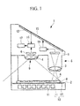
- the specimen observation device 1 includes a stage 2 for placing thereon an accommodating section (hereinafter referred to as a slide tray) B having mounted thereon multiple slides A containing pathology specimens and arrayed in a matrix, two objective lenses 3 and 4 provided above the stage 2 with a gap therebetween, and two image capturing devices 5 and 6 that capture light collected by the respective objective lenses 3 and 4.
- a stage 2 for placing thereon an accommodating section (hereinafter referred to as a slide tray) B having mounted thereon multiple slides A containing pathology specimens and arrayed in a matrix
- two objective lenses 3 and 4 provided above the stage 2 with a gap therebetween
- two image capturing devices 5 and 6 that capture light collected by the respective objective lenses 3 and 4.
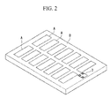
- the slide tray B is a sheet-shaped unit having multiple recesses for individually holding multiple slides A.
- the slide tray B is made of a light-transmitting material or has an opening (not shown) through which light can be transmitted. Furthermore, on a portion of the surface thereof, the slide tray has a barcode 7 containing identification information that is unique to each slide tray B.
- the objective lens 3 and the image capturing device 5 constitute a first image capturing unit 8, which has a field of view that makes it possible to acquire a partial image representing at least a part of the pathology specimen on each of the slides A.
- the other objective lens 4 and the other image capturing device 6 constitute a second image capturing unit 9, which has a field of view that makes it possible to acquire a whole image of the whole slide tray B having mounted thereon the multiple slides A.
- the stage 2 is provided with an illuminating device 10.
- the illuminating device 10 light sources 11 are covered from above with a milky-white (opal-glass) X-ray film viewer 12, which makes it possible to uniformly illuminate the whole slide tray B mounted on the stage 2 from under the slide tray B.
- the specimen observation device 1 includes a monitor (display unit) 13 that displays an enlarged version of the partial image acquired by the first image capturing unit 8.
- the objective lens 3 has a magnification of about two, so that it is possible to acquire a partial image in which a pathology specimen is optically enlarged by two.
- the partial image can be enlarged by a first image processing unit 14 by a display magnification, and the resulting enlarged image is displayed on the monitor 13. This makes it possible for an observer to check, on the monitor 13, whether a lesion is present or not more easily and accurately compared with the case where the observer visually inspects the pathology specimen.
- a touchscreen sensor 15 is provided on the screen of the monitor 13.
- the touchscreen sensor 15 is used to designate the displayed partial image itself or a partial region in the partial image. That is, the observer can touch the touchscreen sensor 15 so as to identify a displayed lesion while viewing the partial image displayed on the monitor 13 to designate (assign a "C" mark to) the partial image itself or the position of a partial region in the partial image.
- the specimen observation device 1 includes a second image processing unit 16 that processes the whole image acquired by the second image capturing unit 9 and a storage unit 17 that stores information generated by the second image processing unit 16.
- the second image processing unit 16 processes the whole image to read identification information from the barcode 7 and to associate the read identification information, as well as the partial image or the position of the partial region designated by the touchscreen sensor 15, with the whole image.
- the first image capturing unit 8 and the second image capturing unit 9 are provided in a fixed positional relationship relative to each other, the position of the partial image acquired by the first image capturing unit 8 in the whole image acquired by the second image capturing unit 9 is known.
- the storage unit 17 is a computer-readable storage medium, such as a semiconductor memory, a magnetic disk, or a magneto-optical disk, provided in a personal computer, a server, etc.
- the slide tray B with multiple slides A mounted thereon is placed on the stage 2.
- the whole slide tray B is uniformly illuminated by light emitted from the illuminating device 10, and images are captured by the first image capturing unit 8 and the second image capturing unit 9. Since the whole slide tray B is located in the field of view of the second image capturing unit 9, it is possible to acquire the whole image of the slide tray B with the multiple slides A mounted thereon.
- identification information is read from the image of the barcode 7 included in the whole image by the operation of the second image processing unit 16. The identification information that has been read is stored in the storage unit 17 in association with the whole image.
- the first image capturing unit 8 captures a partial image of one of the slides A mounted on the slide tray B, and the acquired partial image is enlarged, and the enlarged image is displayed on the monitor 13.
- the observer can shift the image capturing region of the first image capturing unit 8 by manually moving the slide tray B on the stage 2 in the horizontal direction to successively switch the partial image that is displayed on the monitor 13. Since the positions of the first image capturing unit 8 and the second image capturing unit 9 relative to each other are fixed, the position of the slide A represented in the partial image displayed on the monitor 13, in relation to the whole image, is known.
- the observer observes the enlarged partial image displayed on the monitor 13 while moving the slide tray B.
- the observer touches the corresponding region on the monitor 13.
- the partial image or the position of the region in the partial image designated by using the touchscreen sensor 15 is stored in the storage unit 17 in association with the whole image of the slide tray B by the second image processing unit 16, as shown in Fig. 3 .
- the observer observes enlarged images of all the slides A by moving the slide tray B, and directly designates partial images or regions on the monitor 13 by using the touchscreen sensor 15. All these partial images and regions are stored in the storage unit 17 in association with the corresponding whole images.
- the observer can readily check which slides A on the slide tray B contained regions suspected of being lesions. For slides A containing pathology specimens including such regions suspected of being lesions, the observer can further conduct detailed observation using a high-magnification microscope.
- the storage unit 17 is connected via a network (not shown) to a server installed in the vicinity of the high-magnification microscope, by reading the barcode 7 of the slide tray B, transmitted to the server, it is possible to readily check the whole images as well as the pathology specimens to which "C" marks have been assigned as suspected lesions, stored in the storage unit 17 in association with the identification information.
- a network not shown
- the storage unit 17 is connected via a network (not shown) to a server installed in the vicinity of the high-magnification microscope, by reading the barcode 7 of the slide tray B, transmitted to the server, it is possible to readily check the whole images as well as the pathology specimens to which "C" marks have been assigned as suspected lesions, stored in the storage unit 17 in association with the identification information.
- the specimen observation device 1 As described above, with the specimen observation device 1 according to this embodiment, it is possible to quickly observe the multiple slides A mounted on the slide tray B at a low magnification and to store, together with the identification information, the whole images of the slides A containing suspected lesions, in which the suspected lesions are indicated by "C" marks. Thus, there is no need to spend time to acquire virtual slide images for all the slides A as before. Accordingly, an advantage is afforded in that it is possible to readily observe pathology specimens in a short time and to readily observe suspected pathology specimens in detail.
- identification information is read from the barcode 7 by processing a whole image acquired by the second image capturing unit 9 in the embodiment described above, alternatively, a barcode reader may be provided separately. Furthermore, as the input unit for inputting identification information, an input unit that enables manual input, such as a keyboard, may be adopted.
- the barcode 7 may be one-dimensional or two-dimensional, and other types of identification sign may be used instead of the barcode 7.
- the stage 2 may be automatically or semi-automatically moved in the horizontal direction, while fixing the slide tray B on the stage 2. This makes it possible to observe all the slides A on the slide tray B without missing any.
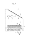
- the image capturing unit 20 is implemented by a microlens array formed of multiple microlenses 18 arrayed horizontally with gaps therebetween above the stage 2 and multiple imaging devices 19, such as CCDs or CMOSs, provided further above the microlens array.
- the pixel pitch of the CCDs may be about 5 ⁇ m
- the pixel pitch of the CMOSs may be 1 to 2 ⁇ m, which makes it possible to acquire a whole image with high precision.
- an image capturing unit 23 that acquires a two-dimensional whole image by horizontally moving a cylindrical lens 21 and a line sensor 22 provided above the slide tray B may be adopted.
- the reference sign 24 denotes a guide rail that supports the image capturing unit 23 such that the image capturing unit 23 can be moved horizontally. This also makes it possible to acquire a whole image with high precision, to extract partial images with high precision corresponding to the individual slides A from the whole image, and to observe enlarged images.
- the second image processing unit 16 may process the whole image, read the identification information of each of the slides A from the barcode (not shown) attached thereto, and store the identification information in the storage unit 17 in association with a macro image of the slide A. This makes it possible to determine whether or not detailed observation is needed from the identification information of the slide A even after the slide A is removed from the slide tray B.
Landscapes
- Engineering & Computer Science (AREA)
- Physics & Mathematics (AREA)
- Multimedia (AREA)
- General Physics & Mathematics (AREA)
- General Engineering & Computer Science (AREA)
- Theoretical Computer Science (AREA)
- Analytical Chemistry (AREA)
- Chemical & Material Sciences (AREA)
- Optics & Photonics (AREA)
- Computer Vision & Pattern Recognition (AREA)
- Signal Processing (AREA)
- Human Computer Interaction (AREA)
- Microscoopes, Condenser (AREA)
Abstract
Description
- The present invention relates to specimen observation devices.
- In the related art, pathology specimens are observed in order to diagnose pathological conditions of cells themselves by examining the sizes of the cell nuclei, cell heteromorphism, etc. or in order to diagnose whether or not the tissue of the specimen as a whole has developed cancer by examining the conditions of multiple cells or intercellular substances. In the case where tissue is to be diagnosed, the whole slide specimen is observed to check whether or not any abnormal shape is present.
- When pathology specimens are supplied, usually, multiple (e.g., 24) specimens are mounted on a slide tray, which is an accommodating section in the shape of a single sheet, and the observer has to observe all the pathology specimens. There are known devices for acquiring images of multiple pathology specimens mounted on a slide tray (e.g., see Non Patent Literature 1).
- "TOCO", CLARO Inc., a product information webpage (URL: http://www.claro-inc.jp/product/toco) retrieved online by an Internet search conducted on May 21, 2014.
- However, such devices are used to acquire virtual slide images of the individual pathology specimens mounted on the slide tray, and there is a problem in that it is necessary to spend an enormous amount of time to acquire virtual slide images even for pathology specimens that can be apparently judged as involving no problem by a simple observation.
- The present invention has been made in view of the situation described above, and it is an object thereof to provide a specimen observation device with which it is possible to readily observe pathology specimens without spending much time and to readily observe suspected pathology specimens in detail.
- In order to achieve the above object, the present invention provides the following solutions.
- The present invention, in one aspect thereof, provides a specimen observation device including an image capturing unit that acquires a partial image representing at least a part of one of multiple pathology specimens mounted on an accommodating section and a whole image of the multiple pathology specimens mounted on the accommodating section; an input unit for inputting identification information of the accommodating section; a display unit that displays an enlarged version of the partial image acquired by the image capturing unit; an image designating unit for designating the partial image displayed on the display unit; and a storage unit that stores the identification information input via the input unit and a position of the partial image designated via the image designating unit in relation to the whole image such that the position and the identification information are associated with the whole image.
- According to this aspect, the image capturing unit acquires a whole image of the accommodating section having multiple pathology specimens mounted thereon, and also acquires a partial image of at least a part of one of the pathology specimens. The partial image is enlarged, and the enlarged partial image is displayed on the display unit. An observer can readily determine whether a lesion is present or not by checking the enlarged image of the pathology specimen, displayed on the display unit.
- Then, in the case where there is no lesion, it is possible to move the accommodating section relative to the image capturing unit, thus readily switching to and displaying on the display unit another pathology specimen located at a different position. On the other hand, in the case where there is any suspected lesion, it is possible to designate, via the image designating unit, the partial image that is currently displayed on the display unit. Furthermore, it is possible to input the identification information of the accommodating section via the input unit.
- Thus, when the partial image is designated, the position of the designated partial image in relation to the whole image and the identification information input via the input unit are stored in the storage unit in association with the whole image. Accordingly, by reading the stored information using the identification information as a key, it is possible to readily determine pathology specimens for which detailed observation is needed among the pathology specimens mounted on the accommodating section.
- In the above aspect, the input unit may be a reading unit that reads the identification information attached to the accommodating section.
- In this case, since the identification information attached to the accommodating section is read by the operation of the reading unit, it is possible to readily associate the identification information with the whole image without performing a special reading operation.
- In the above aspect, the identification information may be recorded on a surface of the accommodating section in a form of a barcode.
- In the above aspect, the input unit may read the identification information from the barcode included in the whole image acquired by the image capturing unit.
- In this case, the image capturing unit also functions as a reading unit, rather than providing a special reading unit, and it is possible to read identification information in the form of a barcode by acquiring a whole image.
- In the above aspect, the image designating unit may be a touchscreen sensor provided on the display unit.
- In this case, in the case where there is any suspected lesion in the enlarged partial image of the pathology specimen, displayed on the display unit, it is possible to readily designate the position of the lesion in the whole image by directly touching the corresponding region on the display unit.
- According to the present invention, an advantage is afforded in that it is possible to readily observe pathology specimens without spending much time and to readily observe suspected pathology specimens in detail.
-
- {
Fig. 1 }
Fig. 1 is a vertical sectional view showing a specimen observation device according to an embodiment of the present invention. - {
Fig. 2 }
Fig. 2 is a perspective view showing an example of a slide tray supporting pathology specimens in the specimen observation device shown inFig. 1 . - {
Fig. 3 }
Fig. 3 is an illustration showing an example of an image that is stored in a storage unit, in which marks are assigned to a whole image acquired by the specimen observation device shown inFig. 1 . - {
Fig. 4 }
Fig. 4 is a vertical sectional view showing a modification of the specimen observation device shown inFig. 1 . - {
Fig. 5 }
Fig. 5 is a vertical sectional view showing another modification of the specimen observation device shown inFig. 1 . - A specimen observation device 1 according to a first embodiment of the present invention will be described below with reference to the drawings.
- As shown in
Fig. 1 , the specimen observation device 1 according to this embodiment includes a stage 2 for placing thereon an accommodating section (hereinafter referred to as a slide tray) B having mounted thereon multiple slides A containing pathology specimens and arrayed in a matrix, twoobjective lenses 3 and 4 provided above the stage 2 with a gap therebetween, and two image capturingdevices 5 and 6 that capture light collected by the respectiveobjective lenses 3 and 4. - As shown in
Fig. 2 , the slide tray B is a sheet-shaped unit having multiple recesses for individually holding multiple slides A. The slide tray B is made of a light-transmitting material or has an opening (not shown) through which light can be transmitted. Furthermore, on a portion of the surface thereof, the slide tray has abarcode 7 containing identification information that is unique to each slide tray B. - The objective lens 3 and the image capturing device 5 constitute a first
image capturing unit 8, which has a field of view that makes it possible to acquire a partial image representing at least a part of the pathology specimen on each of the slides A. - The other
objective lens 4 and the otherimage capturing device 6 constitute a second image capturing unit 9, which has a field of view that makes it possible to acquire a whole image of the whole slide tray B having mounted thereon the multiple slides A. - The stage 2 is provided with an
illuminating device 10. In theilluminating device 10,light sources 11 are covered from above with a milky-white (opal-glass)X-ray film viewer 12, which makes it possible to uniformly illuminate the whole slide tray B mounted on the stage 2 from under the slide tray B. - Furthermore, the specimen observation device 1 according to this embodiment includes a monitor (display unit) 13 that displays an enlarged version of the partial image acquired by the first
image capturing unit 8. Specifically, the objective lens 3 has a magnification of about two, so that it is possible to acquire a partial image in which a pathology specimen is optically enlarged by two. Furthermore, the partial image can be enlarged by a firstimage processing unit 14 by a display magnification, and the resulting enlarged image is displayed on themonitor 13. This makes it possible for an observer to check, on themonitor 13, whether a lesion is present or not more easily and accurately compared with the case where the observer visually inspects the pathology specimen. - On the screen of the
monitor 13, atouchscreen sensor 15 is provided. Thetouchscreen sensor 15 is used to designate the displayed partial image itself or a partial region in the partial image. That is, the observer can touch thetouchscreen sensor 15 so as to identify a displayed lesion while viewing the partial image displayed on themonitor 13 to designate (assign a "C" mark to) the partial image itself or the position of a partial region in the partial image. - Furthermore, the specimen observation device 1 according to this embodiment includes a second
image processing unit 16 that processes the whole image acquired by the second image capturing unit 9 and astorage unit 17 that stores information generated by the secondimage processing unit 16. - The second
image processing unit 16 processes the whole image to read identification information from thebarcode 7 and to associate the read identification information, as well as the partial image or the position of the partial region designated by thetouchscreen sensor 15, with the whole image. - That is, since the first
image capturing unit 8 and the second image capturing unit 9 are provided in a fixed positional relationship relative to each other, the position of the partial image acquired by the firstimage capturing unit 8 in the whole image acquired by the second image capturing unit 9 is known. - Therefore, when the partial image itself or a partial region thereof is designated by using the
touchscreen sensor 15, it is possible to readily identify the designated partial image or the position of the designated partial region. - The
storage unit 17 is a computer-readable storage medium, such as a semiconductor memory, a magnetic disk, or a magneto-optical disk, provided in a personal computer, a server, etc. - Now, the operation of the thus-configured specimen observation device 1 according to this embodiment will be described below.
- In order to observe pathology specimens by using the specimen observation device 1 according to this embodiment, the slide tray B with multiple slides A mounted thereon is placed on the stage 2.
- Then, the whole slide tray B is uniformly illuminated by light emitted from the illuminating
device 10, and images are captured by the firstimage capturing unit 8 and the second image capturing unit 9. Since the whole slide tray B is located in the field of view of the second image capturing unit 9, it is possible to acquire the whole image of the slide tray B with the multiple slides A mounted thereon. After the whole image is acquired, identification information is read from the image of thebarcode 7 included in the whole image by the operation of the secondimage processing unit 16. The identification information that has been read is stored in thestorage unit 17 in association with the whole image. - Meanwhile, the first
image capturing unit 8 captures a partial image of one of the slides A mounted on the slide tray B, and the acquired partial image is enlarged, and the enlarged image is displayed on themonitor 13. The observer can shift the image capturing region of the firstimage capturing unit 8 by manually moving the slide tray B on the stage 2 in the horizontal direction to successively switch the partial image that is displayed on themonitor 13. Since the positions of the firstimage capturing unit 8 and the second image capturing unit 9 relative to each other are fixed, the position of the slide A represented in the partial image displayed on themonitor 13, in relation to the whole image, is known. - Then, the observer observes the enlarged partial image displayed on the
monitor 13 while moving the slide tray B. In the case where there is any region suspected of being a lesion, the observer touches the corresponding region on themonitor 13. Then, the partial image or the position of the region in the partial image designated by using thetouchscreen sensor 15 is stored in thestorage unit 17 in association with the whole image of the slide tray B by the secondimage processing unit 16, as shown inFig. 3 . The observer observes enlarged images of all the slides A by moving the slide tray B, and directly designates partial images or regions on themonitor 13 by using thetouchscreen sensor 15. All these partial images and regions are stored in thestorage unit 17 in association with the corresponding whole images. - Thus, by observing low-magnification enlarged images of the multiple slides A on a single slide tray B and then reading information stored in the
storage unit 17, the observer can readily check which slides A on the slide tray B contained regions suspected of being lesions. For slides A containing pathology specimens including such regions suspected of being lesions, the observer can further conduct detailed observation using a high-magnification microscope. - For example, even in the case where the high-magnification microscope is located at a remote place, if the
storage unit 17 is connected via a network (not shown) to a server installed in the vicinity of the high-magnification microscope, by reading thebarcode 7 of the slide tray B, transmitted to the server, it is possible to readily check the whole images as well as the pathology specimens to which "C" marks have been assigned as suspected lesions, stored in thestorage unit 17 in association with the identification information. Thus, it is possible to extract the slides A containing the pathology specimens having "C" marks assigned thereto from the slide tray B and to conduct detailed observation. - As described above, with the specimen observation device 1 according to this embodiment, it is possible to quickly observe the multiple slides A mounted on the slide tray B at a low magnification and to store, together with the identification information, the whole images of the slides A containing suspected lesions, in which the suspected lesions are indicated by "C" marks. Thus, there is no need to spend time to acquire virtual slide images for all the slides A as before. Accordingly, an advantage is afforded in that it is possible to readily observe pathology specimens in a short time and to readily observe suspected pathology specimens in detail.
- Although identification information is read from the
barcode 7 by processing a whole image acquired by the second image capturing unit 9 in the embodiment described above, alternatively, a barcode reader may be provided separately. Furthermore, as the input unit for inputting identification information, an input unit that enables manual input, such as a keyboard, may be adopted. Thebarcode 7 may be one-dimensional or two-dimensional, and other types of identification sign may be used instead of thebarcode 7. - Furthermore, although the slide tray B is manually moved in the horizontal direction on the stage 2 in the embodiment described above, alternatively, the stage 2 may be automatically or semi-automatically moved in the horizontal direction, while fixing the slide tray B on the stage 2. This makes it possible to observe all the slides A on the slide tray B without missing any.
- Furthermore, although partial images and a whole image are acquired by two image capturing units in the embodiment described above, namely, the first
image capturing unit 8 and the second image capturing unit 9, alternatively, a singleimage capturing unit 20 that can acquire a whole image may be configured. As shown inFig. 4 , theimage capturing unit 20 is implemented by a microlens array formed ofmultiple microlenses 18 arrayed horizontally with gaps therebetween above the stage 2 andmultiple imaging devices 19, such as CCDs or CMOSs, provided further above the microlens array. The pixel pitch of the CCDs may be about 5 µm, whereas the pixel pitch of the CMOSs may be 1 to 2 µm, which makes it possible to acquire a whole image with high precision. Thus, even if partial images corresponding to individual slides A are extracted from the whole image, it is possible to observe enlarged images with high precision. - Alternatively, as shown in
Fig. 5 , animage capturing unit 23 that acquires a two-dimensional whole image by horizontally moving acylindrical lens 21 and aline sensor 22 provided above the slide tray B may be adopted. In the figure, thereference sign 24 denotes a guide rail that supports theimage capturing unit 23 such that theimage capturing unit 23 can be moved horizontally. This also makes it possible to acquire a whole image with high precision, to extract partial images with high precision corresponding to the individual slides A from the whole image, and to observe enlarged images. - Furthermore, although identification information is read from the
barcode 7 attached to the slide tray B by processing the whole image acquired by the second image capturing unit 9 in the embodiment described above, the secondimage processing unit 16 may process the whole image, read the identification information of each of the slides A from the barcode (not shown) attached thereto, and store the identification information in thestorage unit 17 in association with a macro image of the slide A. This makes it possible to determine whether or not detailed observation is needed from the identification information of the slide A even after the slide A is removed from the slide tray B. -
- A
- slides (pathology specimens)
- B
- slide tray (accommodating section)
- 1
- specimen observation device
- 7
- barcode
- 8
- first image capturing unit (image capturing unit)
- 9
- second image capturing unit (image capturing unit)
- 13
- monitor (display unit)
- 15
- touchscreen sensor (image designating unit)
- 16
- second image processing unit (input unit)
- 17
- storage unit
- 20, 23
- image capturing units
Claims (6)
- A specimen observation device comprising:an image capturing unit that acquires a partial image representing at least a part of one of multiple pathology specimens mounted on an accommodating section and a whole image of the multiple pathology specimens mounted on the accommodating section;an input unit for inputting identification information of the accommodating section;a display unit that displays an enlarged version of the partial image acquired by the image capturing unit;an image designating unit for designating the partial image displayed on the display unit; anda storage unit that stores the identification information input via the input unit and a position of the partial image designated via the image designating unit in relation to the whole image such that the position and the identification information are associated with the whole image.
- The specimen observation device according to Claim 1, wherein the input unit is a reading unit that reads the identification information attached to the accommodating section.
- The specimen observation device according to Claim 1 or 2, wherein the identification information is recorded on a surface of the accommodating section in a form of a barcode.
- The specimen observation device according to Claim 3,
wherein the input unit reads the identification information from the barcode included in the whole image acquired by the image capturing unit. - The specimen observation device according to any one of Claims 1 to 4, wherein the image designating unit is a touchscreen sensor provided on the display unit.
- A specimen observation device comprising:an image capturing unit that acquires a whole image of multiple pathology specimens mounted on an accommodating section;an input unit for inputting identification information of the accommodating section and/or the pathology specimens;a storage unit that stores the identification information input via the input unit in association with the whole image.
Applications Claiming Priority (1)
| Application Number | Priority Date | Filing Date | Title |
|---|---|---|---|
| JP2014141518A JP6469977B2 (en) | 2014-07-09 | 2014-07-09 | Specimen observation apparatus and specimen observation method |
Publications (1)
| Publication Number | Publication Date |
|---|---|
| EP2966493A1 true EP2966493A1 (en) | 2016-01-13 |
Family
ID=53539545
Family Applications (1)
| Application Number | Title | Priority Date | Filing Date |
|---|---|---|---|
| EP15175620.2A Withdrawn EP2966493A1 (en) | 2014-07-09 | 2015-07-07 | Specimen observation device |
Country Status (4)
| Country | Link |
|---|---|
| US (1) | US10129480B2 (en) |
| EP (1) | EP2966493A1 (en) |
| JP (1) | JP6469977B2 (en) |
| CN (1) | CN105300990A (en) |
Cited By (2)
| Publication number | Priority date | Publication date | Assignee | Title |
|---|---|---|---|---|
| CN110520739A (en) * | 2017-04-13 | 2019-11-29 | 浜松光子学株式会社 | Image obtains system and image acquisition method |
| WO2022117094A1 (en) | 2020-12-04 | 2022-06-09 | Roche Diagnostics (Shanghai) Limited | Method, device, and computer program product for slides processing |
Families Citing this family (10)
| Publication number | Priority date | Publication date | Assignee | Title |
|---|---|---|---|---|
| JP6906992B2 (en) * | 2017-03-24 | 2021-07-21 | オリンパス株式会社 | Display control system, display control method, and program |
| JP7013210B2 (en) | 2017-11-10 | 2022-01-31 | キヤノン株式会社 | Imaging device, imaging method, display device and display method |
| US20200158555A1 (en) * | 2018-11-15 | 2020-05-21 | Hizero Technoogies Co., Ltd. | Liquid level detection system and liquid level detection method |
| WO2020121906A1 (en) * | 2018-12-13 | 2020-06-18 | ソニー株式会社 | Medical assistance system, medical assistance device, and medical assistance method |
| WO2021050421A1 (en) | 2019-09-09 | 2021-03-18 | Paige.Al, Inc. | Systems and methods for processing images of slides for digital pathology |
| CN110556172A (en) * | 2019-09-18 | 2019-12-10 | 杭州智团信息技术有限公司 | Slide filing method, device terminal, slide filing system, and readable storage medium |
| EP4097636A1 (en) * | 2020-01-28 | 2022-12-07 | PAIGE.AI, Inc. | Systems and methods for processing electronic images for computational detection methods |
| CN112150446A (en) * | 2020-09-27 | 2020-12-29 | 郑州中普医疗器械有限公司 | Microscope examination and film reading scanning method, computer equipment and system |
| CN113205709A (en) * | 2021-04-13 | 2021-08-03 | 广东小天才科技有限公司 | Learning content output method and device, electronic equipment and storage medium |
| CN113205031B (en) * | 2021-04-27 | 2025-09-23 | 广东小天才科技有限公司 | Image recognition method, device, terminal device and storage medium |
Citations (4)
| Publication number | Priority date | Publication date | Assignee | Title |
|---|---|---|---|---|
| EP0557871A2 (en) * | 1992-02-18 | 1993-09-01 | Cell Analysis Systems, Inc. | Method and apparatus for automated assay of biological specimens |
| WO2013147610A2 (en) * | 2012-03-30 | 2013-10-03 | Jetze Botma | Automated selection of microorganisms and identification using maldi |
| JP2014056192A (en) * | 2012-09-13 | 2014-03-27 | Kyocera Optec Co Ltd | Microscope |
| US20140184778A1 (en) * | 2012-12-28 | 2014-07-03 | Canon Kabushiki Kaisha | Image processing apparatus, control method for the same, image processing system, and program |
Family Cites Families (7)
| Publication number | Priority date | Publication date | Assignee | Title |
|---|---|---|---|---|
| JP2000209324A (en) * | 1999-01-12 | 2000-07-28 | Nec Corp | Destination calling control system/method |
| US20060075362A1 (en) * | 2004-10-01 | 2006-04-06 | Kiyotaka Moteki | Image processing apparatus, method, and recording medium on which program is recorded for displaying thumbnail/preview image |
| JP2007298444A (en) * | 2006-05-01 | 2007-11-15 | Olympus Corp | Analyzer |
| US8326014B2 (en) * | 2007-09-28 | 2012-12-04 | Cytyc Corporation | Methods and systems for processing biological specimens utilizing multiple wavelengths |
| JP5343762B2 (en) * | 2009-08-25 | 2013-11-13 | 株式会社ニコン | Control device and microscope system using the control device |
| EP3014331B1 (en) * | 2013-06-26 | 2025-01-29 | Huron Technologies International Inc. | Preview station and method for taking preview images of microscope slides |
| JP2015132550A (en) * | 2014-01-14 | 2015-07-23 | 高電工業株式会社 | Specimen inspection device |
-
2014
- 2014-07-09 JP JP2014141518A patent/JP6469977B2/en not_active Expired - Fee Related
-
2015
- 2015-06-29 US US14/754,404 patent/US10129480B2/en active Active
- 2015-07-07 EP EP15175620.2A patent/EP2966493A1/en not_active Withdrawn
- 2015-07-07 CN CN201510394398.6A patent/CN105300990A/en active Pending
Patent Citations (4)
| Publication number | Priority date | Publication date | Assignee | Title |
|---|---|---|---|---|
| EP0557871A2 (en) * | 1992-02-18 | 1993-09-01 | Cell Analysis Systems, Inc. | Method and apparatus for automated assay of biological specimens |
| WO2013147610A2 (en) * | 2012-03-30 | 2013-10-03 | Jetze Botma | Automated selection of microorganisms and identification using maldi |
| JP2014056192A (en) * | 2012-09-13 | 2014-03-27 | Kyocera Optec Co Ltd | Microscope |
| US20140184778A1 (en) * | 2012-12-28 | 2014-07-03 | Canon Kabushiki Kaisha | Image processing apparatus, control method for the same, image processing system, and program |
Cited By (5)
| Publication number | Priority date | Publication date | Assignee | Title |
|---|---|---|---|---|
| CN110520739A (en) * | 2017-04-13 | 2019-11-29 | 浜松光子学株式会社 | Image obtains system and image acquisition method |
| EP3611513A4 (en) * | 2017-04-13 | 2020-12-09 | Hamamatsu Photonics K.K. | IMAGE CAPTURE DEVICE AND IMAGE CAPTURE METHOD |
| US11022621B2 (en) | 2017-04-13 | 2021-06-01 | Hamamatsu Photonics K.K. | Image acquisition system and image acquisition method |
| US12385934B2 (en) | 2017-04-13 | 2025-08-12 | Hamamatsu Photonics K.K. | Image acquisition system and image acquisition method |
| WO2022117094A1 (en) | 2020-12-04 | 2022-06-09 | Roche Diagnostics (Shanghai) Limited | Method, device, and computer program product for slides processing |
Also Published As
| Publication number | Publication date |
|---|---|
| JP2016018443A (en) | 2016-02-01 |
| JP6469977B2 (en) | 2019-02-13 |
| US20160014343A1 (en) | 2016-01-14 |
| CN105300990A (en) | 2016-02-03 |
| US10129480B2 (en) | 2018-11-13 |
Similar Documents
| Publication | Publication Date | Title |
|---|---|---|
| US10129480B2 (en) | Specimen observation device | |
| US11636627B2 (en) | System for histological examination of tissue specimens | |
| EP3014331B1 (en) | Preview station and method for taking preview images of microscope slides | |
| JP4558047B2 (en) | Microscope system, image generation method, and program | |
| CN110520739B (en) | Image acquisition system and image acquisition method | |
| Jung et al. | Smartphone-based multi-contrast microscope using color-multiplexed illumination | |
| AU2014236055B2 (en) | Referencing in multi-acquisition slide imaging | |
| JP5677770B2 (en) | Medical diagnosis support device, virtual microscope system, and specimen support member | |
| CN105190690A (en) | Image quality assessment of microscopy images | |
| CN116235223A (en) | Annotated data collection using gaze-based tracking | |
| JP7253273B2 (en) | Reproductive medical support system | |
| US20100128962A1 (en) | Virtual-slide specimen image acquisition apparatus | |
| EP2157164A1 (en) | Observation device | |
| Kim et al. | Rapid 3D imaging at cellular resolution for digital cytopathology with a multi-camera array scanner (MCAS) | |
| US11461892B2 (en) | Cell observation system | |
| US20200124836A1 (en) | Cell observation system | |
| EP3816698B1 (en) | Digital pathology scanner for large-area microscopic imaging | |
| JP2012003216A (en) | Device and method for capturing microscopic image | |
| WO2022138254A1 (en) | Glass slide storage rack, slide storage, and glass slide imaging system | |
| JP2004309768A (en) | Microscope system | |
| US7593556B2 (en) | Sample picture data processing method and sample inspection system and method | |
| EP1967841A2 (en) | Fluorescence observation apparatus | |
| JP3003795B2 (en) | Microscope support device | |
| KR20250015748A (en) | Slide scanning apparatus and its operation method | |
| JP2013094127A (en) | Method and apparatus for imaging light transmitting particle |
Legal Events
| Date | Code | Title | Description |
|---|---|---|---|
| PUAI | Public reference made under article 153(3) epc to a published international application that has entered the european phase |
Free format text: ORIGINAL CODE: 0009012 |
|
| AK | Designated contracting states |
Kind code of ref document: A1 Designated state(s): AL AT BE BG CH CY CZ DE DK EE ES FI FR GB GR HR HU IE IS IT LI LT LU LV MC MK MT NL NO PL PT RO RS SE SI SK SM TR |
|
| AX | Request for extension of the european patent |
Extension state: BA ME |
|
| 17P | Request for examination filed |
Effective date: 20160712 |
|
| RBV | Designated contracting states (corrected) |
Designated state(s): AL AT BE BG CH CY CZ DE DK EE ES FI FR GB GR HR HU IE IS IT LI LT LU LV MC MK MT NL NO PL PT RO RS SE SI SK SM TR |
|
| RAP1 | Party data changed (applicant data changed or rights of an application transferred) |
Owner name: OLYMPUS CORPORATION |
|
| RAP1 | Party data changed (applicant data changed or rights of an application transferred) |
Owner name: OLYMPUS CORPORATION |
|
| RIN1 | Information on inventor provided before grant (corrected) |
Inventor name: KAWANO, YOSHIHIRO |
|
| STAA | Information on the status of an ep patent application or granted ep patent |
Free format text: STATUS: THE APPLICATION HAS BEEN WITHDRAWN |
|
| 18W | Application withdrawn |
Effective date: 20190228 |