EP2966344A1 - Optical module with lens for motor vehicle projector headlamp - Google Patents
Optical module with lens for motor vehicle projector headlamp Download PDFInfo
- Publication number
- EP2966344A1 EP2966344A1 EP15174223.6A EP15174223A EP2966344A1 EP 2966344 A1 EP2966344 A1 EP 2966344A1 EP 15174223 A EP15174223 A EP 15174223A EP 2966344 A1 EP2966344 A1 EP 2966344A1
- Authority
- EP
- European Patent Office
- Prior art keywords
- mask
- module
- positioning
- optical module
- projection
- Prior art date
- Legal status (The legal status is an assumption and is not a legal conclusion. Google has not performed a legal analysis and makes no representation as to the accuracy of the status listed.)
- Granted
Links
- 230000003287 optical effect Effects 0.000 title claims abstract description 143
- 230000011664 signaling Effects 0.000 claims abstract description 14
- 210000002105 tongue Anatomy 0.000 description 17
- 235000005921 Cynara humilis Nutrition 0.000 description 6
- 240000002228 Cynara humilis Species 0.000 description 6
- 230000004224 protection Effects 0.000 description 6
- 230000001681 protective effect Effects 0.000 description 6
- 230000009131 signaling function Effects 0.000 description 5
- YMHOBZXQZVXHBM-UHFFFAOYSA-N 2,5-dimethoxy-4-bromophenethylamine Chemical compound COC1=CC(CCN)=C(OC)C=C1Br YMHOBZXQZVXHBM-UHFFFAOYSA-N 0.000 description 3
- 241000545067 Venus Species 0.000 description 3
- 230000006870 function Effects 0.000 description 3
- 241000920340 Pion Species 0.000 description 2
- 238000012550 audit Methods 0.000 description 2
- 238000005286 illumination Methods 0.000 description 2
- 230000000670 limiting effect Effects 0.000 description 2
- 239000002964 rayon Substances 0.000 description 2
- 229910052782 aluminium Inorganic materials 0.000 description 1
- XAGFODPZIPBFFR-UHFFFAOYSA-N aluminium Chemical compound [Al] XAGFODPZIPBFFR-UHFFFAOYSA-N 0.000 description 1
- 230000015572 biosynthetic process Effects 0.000 description 1
- 230000000295 complement effect Effects 0.000 description 1
- 238000010276 construction Methods 0.000 description 1
- 238000002788 crimping Methods 0.000 description 1
- 238000013016 damping Methods 0.000 description 1
- 230000007547 defect Effects 0.000 description 1
- 238000006073 displacement reaction Methods 0.000 description 1
- 230000000694 effects Effects 0.000 description 1
- 238000005401 electroluminescence Methods 0.000 description 1
- 230000004907 flux Effects 0.000 description 1
- 238000012423 maintenance Methods 0.000 description 1
- 238000004519 manufacturing process Methods 0.000 description 1
- 229910052751 metal Inorganic materials 0.000 description 1
- 239000002184 metal Substances 0.000 description 1
- 230000010355 oscillation Effects 0.000 description 1
- 239000002861 polymer material Substances 0.000 description 1
- 230000005855 radiation Effects 0.000 description 1
- 230000009183 running Effects 0.000 description 1
- 238000000926 separation method Methods 0.000 description 1
- 230000008093 supporting effect Effects 0.000 description 1
Images


Classifications
-
- F—MECHANICAL ENGINEERING; LIGHTING; HEATING; WEAPONS; BLASTING
- F21—LIGHTING
- F21S—NON-PORTABLE LIGHTING DEVICES; SYSTEMS THEREOF; VEHICLE LIGHTING DEVICES SPECIALLY ADAPTED FOR VEHICLE EXTERIORS
- F21S41/00—Illuminating devices specially adapted for vehicle exteriors, e.g. headlamps
- F21S41/10—Illuminating devices specially adapted for vehicle exteriors, e.g. headlamps characterised by the light source
- F21S41/19—Attachment of light sources or lamp holders
-
- F—MECHANICAL ENGINEERING; LIGHTING; HEATING; WEAPONS; BLASTING
- F21—LIGHTING
- F21S—NON-PORTABLE LIGHTING DEVICES; SYSTEMS THEREOF; VEHICLE LIGHTING DEVICES SPECIALLY ADAPTED FOR VEHICLE EXTERIORS
- F21S41/00—Illuminating devices specially adapted for vehicle exteriors, e.g. headlamps
- F21S41/10—Illuminating devices specially adapted for vehicle exteriors, e.g. headlamps characterised by the light source
- F21S41/14—Illuminating devices specially adapted for vehicle exteriors, e.g. headlamps characterised by the light source characterised by the type of light source
- F21S41/141—Light emitting diodes [LED]
- F21S41/147—Light emitting diodes [LED] the main emission direction of the LED being angled to the optical axis of the illuminating device
- F21S41/148—Light emitting diodes [LED] the main emission direction of the LED being angled to the optical axis of the illuminating device the main emission direction of the LED being perpendicular to the optical axis
-
- F—MECHANICAL ENGINEERING; LIGHTING; HEATING; WEAPONS; BLASTING
- F21—LIGHTING
- F21S—NON-PORTABLE LIGHTING DEVICES; SYSTEMS THEREOF; VEHICLE LIGHTING DEVICES SPECIALLY ADAPTED FOR VEHICLE EXTERIORS
- F21S41/00—Illuminating devices specially adapted for vehicle exteriors, e.g. headlamps
- F21S41/20—Illuminating devices specially adapted for vehicle exteriors, e.g. headlamps characterised by refractors, transparent cover plates, light guides or filters
- F21S41/29—Attachment thereof
- F21S41/295—Attachment thereof specially adapted to projection lenses
-
- F—MECHANICAL ENGINEERING; LIGHTING; HEATING; WEAPONS; BLASTING
- F21—LIGHTING
- F21S—NON-PORTABLE LIGHTING DEVICES; SYSTEMS THEREOF; VEHICLE LIGHTING DEVICES SPECIALLY ADAPTED FOR VEHICLE EXTERIORS
- F21S41/00—Illuminating devices specially adapted for vehicle exteriors, e.g. headlamps
- F21S41/30—Illuminating devices specially adapted for vehicle exteriors, e.g. headlamps characterised by reflectors
- F21S41/39—Attachment thereof
-
- F—MECHANICAL ENGINEERING; LIGHTING; HEATING; WEAPONS; BLASTING
- F21—LIGHTING
- F21S—NON-PORTABLE LIGHTING DEVICES; SYSTEMS THEREOF; VEHICLE LIGHTING DEVICES SPECIALLY ADAPTED FOR VEHICLE EXTERIORS
- F21S41/00—Illuminating devices specially adapted for vehicle exteriors, e.g. headlamps
- F21S41/50—Illuminating devices specially adapted for vehicle exteriors, e.g. headlamps characterised by aesthetic components not otherwise provided for, e.g. decorative trim, partition walls or covers
- F21S41/55—Attachment thereof
-
- F—MECHANICAL ENGINEERING; LIGHTING; HEATING; WEAPONS; BLASTING
- F21—LIGHTING
- F21S—NON-PORTABLE LIGHTING DEVICES; SYSTEMS THEREOF; VEHICLE LIGHTING DEVICES SPECIALLY ADAPTED FOR VEHICLE EXTERIORS
- F21S45/00—Arrangements within vehicle lighting devices specially adapted for vehicle exteriors, for purposes other than emission or distribution of light
- F21S45/40—Cooling of lighting devices
- F21S45/47—Passive cooling, e.g. using fins, thermal conductive elements or openings
- F21S45/48—Passive cooling, e.g. using fins, thermal conductive elements or openings with means for conducting heat from the inside to the outside of the lighting devices, e.g. with fins on the outer surface of the lighting device
-
- F—MECHANICAL ENGINEERING; LIGHTING; HEATING; WEAPONS; BLASTING
- F21—LIGHTING
- F21S—NON-PORTABLE LIGHTING DEVICES; SYSTEMS THEREOF; VEHICLE LIGHTING DEVICES SPECIALLY ADAPTED FOR VEHICLE EXTERIORS
- F21S45/00—Arrangements within vehicle lighting devices specially adapted for vehicle exteriors, for purposes other than emission or distribution of light
- F21S45/40—Cooling of lighting devices
- F21S45/49—Attachment of the cooling means
Definitions
- the technical field of the present invention is that of projectors with lens illumination module, in particular for motor vehicles.
- lens illumination module is meant a device which comprises a light source, a reflector, and a lens through which the luminous flux concentrated by the reflector passes. It may be more particularly a so-called elliptical module, in which the reflector is in the general shape of ellipsoid and has a first focus to which is placed the light source and a second focus in the vicinity of which passes the focal plane of the lens .
- the lens is fixed on a support element, made of sheet metal or the like, using tabs formed in the sheet and folded towards the inside of the support element, so as to trap the lens, in possible cooperation with a retracting collar or the like of said element, in the region of the periphery of the lens.
- the document DE 3516813 teaches such a lens mount.
- the module comprises a light source, a reflector, a lens interposed in the path of the radiation concentrated by the reflector, and a means for supporting the lens.
- the maintenance of the lens is made by pinching between two elements that fit into one another.
- the module described in the aforementioned document lacks rigidity. Since the lens is a massive and heavy piece, there is a risk that the lens will vibrate, causing the flickering of the light beam and / or the separation of the lens of the entire module. In addition, if the oscillation phenomenon of the lens persists, this can lead to the rupture of the lens.
- the object of the present invention is therefore to overcome the disadvantages of the prior art by providing a simple and compact construction lens lighting module with a new way of fixing the lens in the module.
- the subject of the invention is an optical module, in particular for lighting and / or signaling, of a motor vehicle, the optical module being intended to emit a light beam along an optical axis and a given direction, the optical module comprising a light source and an optical projection element, the projection optical element being adapted to cooperate with the light source to project said light beam, the optical module further comprising a heat sink adapted to dissipate the heat emitted by said light source, the dissipator having lower holding means arranged to maintain the projection optical element in said module.
- the invention thus provides protection via an aesthetic piece to the reflector, this aesthetic piece coming between the reflector and other elements external to the module during its mounting in the vehicle.
- the invention also relates to an optical module, including lighting and / or signaling for a motor vehicle, comprising a light source and a lower optical module mask, remarkable in that the lower mask is in accordance with the invention.
- the reflector of the lower mask is intended to cooperate with the light source to generate a light beam along an optical axis and a given direction.
- the invention also relates to an optical module, including lighting and / or signaling for a motor vehicle, comprising a light source and a lower mask according to the invention and an optical projection element.
- the reflector of the lower mask is intended to cooperate with said light source to generate a light beam along a given optical axis and direction
- the projection optical element is arranged to cooperate with the reflector to project said beam.
- the invention also relates to an optical module, including lighting and / or signaling for a motor vehicle, comprising a reflector, an optical projection element and an upper mask according to the invention.
- the protective cover of the upper mask at least partially covering, in particular completely, the reflector of the optical module and the upper holding means maintaining the optical projection element in the module.
- the subject of the invention is an optical module, in particular for lighting and / or signaling, of a motor vehicle, the optical module being intended to emit a light beam along an optical axis and a given direction, the optical module comprising a light source and an optical projection element, the projection optical element being adapted to cooperate with the light source to project said light beam, the optical module further comprising a dissipator heat dissipating heat emitted by said light source, the dissipator having lower holding means arranged to maintain the optical projection element in said module.
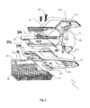
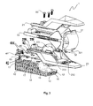
- FIGS. 1 to 5 illustrate the principle of the invention and correspond to a preferred embodiment. They schematically illustrate a lighting and / or signaling module 1, fixed in a housing (not shown) of a projector, comprising a heat sink 10, a mask 20, a lens 30 and a light source 40.
- the lighting and / or signaling module 1 comprises an optical axis 2.
- the heat sink 10 comprises at least one retaining means of the lens 30.
- the retaining means 12 is formed by an outgrowth 12 which is intended to extend into a cavity 321 formed in the lens 30.
- the protrusion 12 takes the form of a paw, a finger, a pawn, or a rod.
- the section of the protrusion is rectangular, square, hexagonal, octagonal, or cross, with projecting or rounded edges.
- the heat sink 10 comprises two protrusions 12.
- the protrusions 12 have the shape of an elongated longitudinal leg Z of which the rectangular section has rounded edges, the free front portion of which engages in the cavity 321 of the lens 30.
- an end ridge can be provided. perpendicular to the flat surface of the front portion of the Z; this ensures that the more effective lens 30 is held in force in the direction of the optical axis 2 of the lens.
- the protuberances 12 are upwardly directed pins (in the direction of the axis Oz). These pins 12 fit into the cavities 321 of the lens 30. The cooperation between the protuberances 12 and the cavities 321 make it possible to block the movements of the lens 30 in two directions.
- the lens 30 comprises at least one lower tongue 32 and at least one cavity 321 formed in the lower tongue 32.
- two cavities 321 are present in the lower tongue 32.
- the lower tongue 32 comprises two emergent cavities 321 and oriented in the direction of the thickness of the tongue 32, cooperating with the two protrusions 12 in projection towards the front.
- the tongue 32 comprises two cavities 321 which are blind holes oriented along the height of the lens 30.
- a damping gasket may be placed at the contact surface between the heat sink 10 and the lens 30 to dampen vibrations due to the vehicle engine.
- the heat sink 10 has fins 11 of heat exchange on its underside.
- the heat sink 10 comprises at least one positioning means for arranging the mask 20 on the heat sink 10 during assembly of the module 1.
- the positioning means is a protrusion 13.
- the protrusion 13 takes the form of a paw, a finger, a pawn, or a rod.
- the section of the protrusion 13 is rectangular, square, hexagonal, octagonal or cross, with projecting or rounded edges.
- the heat sink 10 comprises two protrusions 13 having the form of cruciform fingers in section.
- the heat sink 10 further comprises at least one holding means for the mask 20 and the light source 40.
- the holding means is a screw thread 17 cooperating with a screw 50.
- the heat sink 10 has a second step 17 screw cooperating with a second screw 50 to maintain the mask.
- the heat sink 10 comprises fins 11 under all or part of the first sector 14 and / or the second sector 16 and / or the intermediate sector 15.
- the mask 20 of the module 1 comprises at least two parts: an upper shell 21 and a lower shell 23.
- the mask 20 comprises an upper shell 21, an intermediate shell 22 and a lower shell 23.
- the lower shell 23 comprises a reflective surface 231 providing a lighting function and / or signaling.
- the reflective surface 231 is a parabolic reflector.
- the lighting and / or signaling function is fulfilled by the cooperation of the surface 231 with the light source 40.
- the latter is fixed and positioned on a printed circuit 41, itself fixed on the heat sink 10.
- the printed circuit has cooperating holes 411 with excrescences of the heat sink 10.
- the excrescences are the protrusions 13 described above.
- the printed circuit 41 has openings 42 cooperating with the screws 50. In the embodiment shown in FIGS. Figures 1 to 5 , the printed circuit 41 is held on the heat sink 10 by the cooperation between a screw thread 17 and a screw 50 which also acts as an electrical ground for the printed circuit 41.
- the light source 40 is preferably of the electroluminescence diode (LED) type, and it is located substantially on the optical axis of the lens 30.
- substantially located it is meant that the distance between the light source 40 and the optical axis does not exceed 0.5 mm.
- This lighting and / or signaling function may be a day signaling function, commonly referred to as the DRL (the English acronym for "Daytime Running Light”), a signaling function commonly known as a “night light”, a crossover function, commonly referred to as a "code”, a function commonly referred to as a “road”.
- the reflecting surface 231 thus ensures the formation of a lighting beam and / or signaling directed towards the front of the vehicle.
- the lower shell 23 further comprises an opening 232 for passing the lower tongue 32 of the lens 30. As is more particularly visible on the figure 5 the opening 232 of the lower shell 23 serves to lock the lens 30 in the direction of the optical axis of the lens 30.
- the lower shell 23 comprises holes 234 cooperating with the positioning means 13 of the heat sink 10 to facilitate assembly of the module 10.
- holes 234 are larger in diameter than cruciform fingers 13.
- the lower shell 23 comprises openings 235 cooperating with the holding means of the heat sink 10 for the good behavior of the elements of the module 1 during its use.
- the lower shell 23 comprises positioning means for arranging the intermediate shell 22 on the lower shell 23 during assembly of the module 1.
- the positioning means take the form of a tab, a finger, a pawn, or a rod.
- the section of the protrusion is rectangular, square, hexagonal, octagonal, or cross, with projecting or rounded edges.
- the positioning means 233 are cruciform fingers in section.
- the intermediate shell 22 of the module 1 is a U-shaped part.
- the base of the U comprises holes 221 cooperating with the means for positioning the heat sink 10 in order to facilitate the assembly of the module 10.
- the holes 221 have a diameter greater than that of the cruciform fingers 13.
- the intermediate shell 22 comprises at least one hole 222 on at least one branch of the U cooperating with the cruciform pins 233 of the lower shell 23.
- the hole 221 is present on each branch. The intermediate shell 22 rests on the lower shell 23 and makes it possible to position the upper shell 21.
- the two branches of the U come to pinch the lens 30.
- the ends of the branches of the U opposite the base of the U comprise a lateral cheek with a notch cooperating with an abutment of the lens so as to partially cover at least the lateral faces of the lens 30.
- the intermediate shell 22 is opaque to obscure the LEDs on the side of the module.
- the intermediate shell 22 is black.
- the upper shell 21 comprises at least one abutment 212 accommodating behind at least one upper tongue 31 of the lens 30.
- the upper shell 21 comprises at least one abutment 211 being lodged in front of at least one upper tongue 31 of the lens 30
- the upper shell 21 comprises an abutment 211 and two staggered parallel stops 212 abutting against the edges of the upper tongue 31 of the lens 30.
- the stop 211 is a loop cooperating with an outgrowth 311 situated on the front face of the upper tongue 31 of the lens 30, said protrusion 311 snapping into said snare.
- the upper shell 21 rests on the intermediate shell 22 and is supported on the upper tongue 31 of the lens 30 so that the lens 30 is held by vise between the projections 12 of the heat sink 10 and the upper shell 21 of the mask 20 .
- the upper shell comprises holes 214 cooperating with the positioning means 13 of the heat sink 10 in order to facilitate the assembly of the module 10.
- the holes 214 have a diameter greater than that of the cruciform fingers 13.
- the lens 30 comprises at least one lower tongue 32 provided with at least one hole 321 cooperating with the protrusion 12 on the heat sink 10 so as to block the lens along at least two axes.
- the lens 30 further comprises at least one upper tongue 31 cooperating with at least one stop 21X so as to block the lens along a third axis different from the two previous ones.
- the tongues 31 and 32 of the lens 30 are located on the opposite ends of the lens.
- the lens 30 also comprises a border 33 located on the rear face of the orthogonal projection lens 30.
- the lower part of the border 33 is in contact with the lower shell of the mask 23 in order to prevent the lens 30 from tilting towards the rear of the module 10.
- the light source 40 when the light source 40 is on, it emits light rays towards the reflector 231.
- the reflector returns the light rays towards the front of the vehicle to fill a lighting and / or signaling function. In their path, the light rays pass through the projection lens 30 held in a vice between the tabs 12 of the heat sink 10 and the upper shell 21 of the mask 20.
- the present invention makes it possible in particular to produce modules and lighting projectors, in particular for equipping motor vehicles.
- the PCB (the acronym "Printed Circuit Board” designating the printed circuit board) is screwed on the heat sink.
- the projection lens is assembled with the hubcap thus forming the subassembly 1.
- the brake is fixed to the upper shell thus obtaining the subassembly 2.
- the Subassembly 2 is inserted in Z on the heat sink and then pushing the heat sink in X to lock the lens. We add the upper shell at this time.
- the assembly is then screwed then forming the module.
- the aluminum plate pre-equipped with the cradle made of polymer material is turned upside down.
- the modules "kink” (of the English vriller, to designate the oblique cut of the beam code) and “route” are inserted on the plate in X.
- the modules are upside down. They are maintained in Z by ribs coming from the plate in contact with the upper shell.
- the modules are then screwed on the plate.
- the module "flat” flat English, to designate the flat cut of the beam code
- the adjustment screw of the "flat” module is then inserted and screwed into the "flat” module.
Landscapes
- Engineering & Computer Science (AREA)
- General Engineering & Computer Science (AREA)
- Physics & Mathematics (AREA)
- Microelectronics & Electronic Packaging (AREA)
- Optics & Photonics (AREA)
- Non-Portable Lighting Devices Or Systems Thereof (AREA)
Abstract
L'invention concerne un module optique (1), notamment d'éclairage et/ou de signalisation, d'un véhicule automobile, le module optique étant destiné à émettre un faisceau lumineux selon un axe optique et un sens donnés, le module optique (1) comportant une source lumineuse (40) et un élément optique de projection (30), l'élément optique de projection (30) étant apte à coopérer avec la source lumineuse (40) pour projeter ledit faisceau lumineux, le module optique comportant en outre un dissipateur thermique (10) apte à dissiper de la chaleur émise par ladite source lumineuse (40), le dissipateur (10) comportant des moyens de maintien inférieurs (12) agencés pour maintenir l'élément optique de projection (30) dans ledit module.The invention relates to an optical module (1), especially lighting and / or signaling, of a motor vehicle, the optical module being intended to emit a light beam according to an optical axis and a given direction, the optical module ( 1) comprising a light source (40) and an optical projection element (30), the projection optical element (30) being able to cooperate with the light source (40) to project said light beam, the optical module comprising in addition to a heat sink (10) adapted to dissipate heat emitted by said light source (40), the dissipator (10) having lower holding means (12) arranged to hold the projection optical element (30) in said module.
Description
Le domaine technique de la présente invention est celui des projecteurs avec module d'éclairage à lentille, notamment pour véhicules automobiles.The technical field of the present invention is that of projectors with lens illumination module, in particular for motor vehicles.
On entend par module d'éclairage à lentille un dispositif qui comprend une source lumineuse, un réflecteur, et une lentille traversée par le flux lumineux concentré par le réflecteur. Il peut s'agir plus particulièrement d'un module dit elliptique, dans lequel le réflecteur est en forme générale d'ellipsoïde et possède un premier foyer auquel est placée la source lumineuse et un second foyer au voisinage duquel passe le plan focal de la lentille.By lens illumination module is meant a device which comprises a light source, a reflector, and a lens through which the luminous flux concentrated by the reflector passes. It may be more particularly a so-called elliptical module, in which the reflector is in the general shape of ellipsoid and has a first focus to which is placed the light source and a second focus in the vicinity of which passes the focal plane of the lens .
Classiquement, la lentille est fixée sur un élément de support, en tôle ou analogue, à l'aide de pattes formées dans la tôle et repliées vers l'intérieur de l'élément de support, de manière à emprisonner la lentille, en coopération éventuelle avec un collet rentrant ou analogue dudit élément, dans la région de la périphérie de la lentille. Le document
Ce type de montage connu présente cependant plusieurs inconvénients, liés à l'imprécision inhérente quant à la position géométrique des pattes de sertissage. Ainsi, dans un premier cas, la lentille peut être maintenue dans son élément de support avec un certain jeu, et des déplacements de la lentille dans les limites de ce jeu vont conduire à un défaut de positionnement par rapport au réflecteur et donc à la production d'un faisceau lumineux imparfait. Dans un second cas, les pattes peuvent exercer au contraire un effort de pincement excessif sur les bords de la lentille, ce qui peut conduire à une rupture de la lentille sous l'effet notamment des dilatations thermiques différentielles entre les diverses parties lors de la montée en température du module.This type of known assembly however has several drawbacks, related to the inherent inaccuracy as to the geometric position of the crimping tabs. Thus, in a first case, the lens can be held in its support element with a certain clearance, and displacements of the lens within the limits of this game will lead to a defect in positioning relative to the reflector and therefore to the production. an imperfect light beam. In a second case, the tabs may, on the contrary, exert an excessive pinching force on the edges of the lens, which can lead to a rupture of the lens under the effect in particular of the differential thermal expansion between the various parts during the climb. in temperature of the module.
Une solution pour pallier à ces problèmes de l'art antérieur est présentée dans le brevet
Le module décrit dans le document précité manque de rigidité. La lentille étant une pièce massive et lourde, il y a un risque que la lentille rentre en vibration, provoquant alors le scintillement du faisceau lumineux et/ou la désolidarisation de la lentille de l'ensemble du module. En outre si le phénomène d'oscillation de la lentille perdure, cela peut conduire à la rupture de la lentille.The module described in the aforementioned document lacks rigidity. Since the lens is a massive and heavy piece, there is a risk that the lens will vibrate, causing the flickering of the light beam and / or the separation of the lens of the entire module. In addition, if the oscillation phenomenon of the lens persists, this can lead to the rupture of the lens.
Le but de la présente invention est donc de résoudre les inconvénients de l'art antérieur en proposant un module d'éclairage à lentille de construction simple et compacte avec une nouvelle manière de fixer la lentille dans le module.The object of the present invention is therefore to overcome the disadvantages of the prior art by providing a simple and compact construction lens lighting module with a new way of fixing the lens in the module.
L'invention a pour objet un module optique, notamment d'éclairage et/ou de signalisation, d'un véhicule automobile, le module optique étant destiné à émettre un faisceau lumineux selon un axe optique et un sens donnés, le module optique comportant une source lumineuse et un élément optique de projection, l'élément optique de projection étant apte à coopérer avec la source lumineuse pour projeter ledit faisceau lumineux, le module optique comportant en outre un dissipateur thermique apte à dissiper de la chaleur émise par ladite source lumineuse, le dissipateur comportant des moyens de maintien inférieurs agencés pour maintenir l'élément optique de projection dans ledit module.The subject of the invention is an optical module, in particular for lighting and / or signaling, of a motor vehicle, the optical module being intended to emit a light beam along an optical axis and a given direction, the optical module comprising a light source and an optical projection element, the projection optical element being adapted to cooperate with the light source to project said light beam, the optical module further comprising a heat sink adapted to dissipate the heat emitted by said light source, the dissipator having lower holding means arranged to maintain the projection optical element in said module.
L'invention pourra présenter de manière avantageuse et non limitative l'une ou plusieurs des caractéristiques suivantes :
- le dissipateur thermique présente un profil en escalier, la source lumineuse étant disposée sur une marche haute arrière et les moyens de maintien inférieurs étant disposés sur une marche basse avant ;
- l'élément optique de projection comporte des moyens de tenue inférieurs coopérant avec les moyens de maintien inférieurs de façon à maintenir l'élément optique de projection sur le dissipateur thermique ;
- les moyens de maintien inférieurs du dissipateur thermique comportent au moins une excroissance de ce dissipateur et dans lequel les moyens de tenue inférieurs de l'élément optique de projection comportent au moins un orifice formé dans une patte inférieure de l'élément optique de projection, ladite excroissance s'étendant à travers ledit orifice ;
- les moyens de tenue inférieurs de l'élément optique de projection comporte au moins une excroissance formée dans la patte inférieure de cet élément et dans lequel les moyens de maintien du dissipateur thermique comportent au moins un orifice formé dans ce dissipateur thermique, ladite excroissance s'étendant à travers ledit orifice ;
- le module comporte une carte électronique destinée à alimenter électriquement la source lumineuse, la carte électronique étant portée par le dissipateur thermique ;
- la source lumineuse est montée sur la carte électronique ;
- la source lumineuse est directement montée sur le dissipateur thermique
- le module comprenant un masque inférieur pourvu d'un trou de fixation, le dissipateur thermique comprenant un orifice de fixation et un moyen de fixation du masque inférieur au dissipateur, notamment une vis, le moyen de fixation traversant le trou de fixation du masque inférieur et l'orifice de fixation du dissipateur thermique pour fixer le masque inférieur au dissipateur ;
- le masque inférieur comporte avantageusement un réflecteur, notamment venu de matière, apte à coopérer avec la source lumineuse pour générer ledit faisceau lumineux, l'élément optique de projection étant apte à coopérer avec le réflecteur pour projeter ledit faisceau lumineux ;
- le masque inférieur étant pourvu d'au moins un moyen de positionnement du masque inférieur dans le module et le dissipateur comportant au moins un moyen de positionnement coopérant avec le moyen de positionnement du masque inférieur pour positionner le masque inférieur dans le module optique ;
- le moyen de positionnement du masque inférieur peut être un ergot faisant saillie du masque inférieur tandis que le moyen de positionnement du dissipateur est un trou oblong. En variante non exclusive, le moyen de positionnement du masque inférieur peut être un trou oblong tandis que le moyen de positionnement du dissipateur est un ergot faisant saillie du dissipateur ;
- le masque inférieur comporte des moyens de positionnement inférieurs coopérant avec des organes de positionnement inférieurs de l'élément optique de projection ;
- les moyens de positionnement inférieurs comprennent une ouverture, notamment rectangulaire, s'étendant dans le sens transversal du masque inférieur. Dans ce cas, les organes de positionnement inférieurs de l'élément optique de projection comportent au moins une patte inférieure s'étendant dans l'ouverture du masque inférieure ;
- le module comprend un masque supérieur pourvu d'au moins un trou de fixation, le masque supérieur recouvrant au moins partiellement le masque inférieur, le moyen de fixation du dissipateur traversant le trou de fixation du masque supérieur pour fixer le masque supérieur au dissipateur ;
- le masque supérieur est pourvu d'au moins un moyen de positionnement du masque supérieur dans le module et moyen de positionnement du dissipateur coopérant avec le moyen de positionnement du masque supérieur pour positionner le masque inférieur dans le module optique ;
- le masque supérieur comporte des moyens de maintien supérieurs coopérant avec des moyens de tenue supérieurs de l'élément optique de projection ;
- les moyens de maintien supérieurs comprennent une butée.et/ou une anse. Le cas échéant, les moyens de tenue supérieurs de l'élément optique de projection sont un muret et/ou une excroissance ;
- le module comprend un masque intermédiaire disposé entre le masque supérieur et le masque inférieur ;
- le masque intermédiaire comprend un organe de fixation et des joues latérales d'interception de la lumière ;
- les joues latérales comportent chacune une encoche de positionnement coopérant avec une nervure latérale de l'élément optique de projection pour le positionnement de ladite joue latérale sur l'élément optique de projection ;
- les joues latérales comportent chacune une patte inférieure de positionnement s'insérant dans un orifice de positionnement de la joue formé dans le masque inférieur ;
- l'organe de fixation du masque intermédiaire comporte au moins un orifice de positionnement dans lequel s'insère un pion de positionnement du masque intermédiaire formé sur le masque inférieur.
- the heat sink has a stepped profile, the light source being disposed on a rear high step and the lower holding means being arranged on a low front step;
- the projection optical element comprises lower holding means cooperating with the lower holding means so as to maintain the projection optical element on the heat sink;
- the lower holding means of the heat sink comprise at least one protrusion of this dissipator and in which the lower holding means of the projection optical element comprise at least one orifice formed in a lower leg of the projection optical element, said protrusion extending through said orifice;
- the lower holding means of the projection optical element comprises at least one protrusion formed in the lower leg of this element and wherein the holding means of the heat sink comprise at least one orifice formed in this heat sink, said protrusion s' extending through said orifice;
- the module comprises an electronic card for electrically powering the light source, the electronic card being carried by the heat sink;
- the light source is mounted on the electronic card;
- the light source is directly mounted on the heat sink
- the module comprising a lower mask provided with a fixing hole, the heat sink comprising a fixing orifice and a fixing means of the lower mask to the dissipator, in particular a screw, the fastening means passing through the fixing hole of the lower mask and the heatsink mounting hole for attaching the lower mask to the heatsink;
- the lower mask advantageously comprises a reflector, in particular integral, capable of cooperating with the light source to generate said light beam, the projection optical element being able to cooperate with the reflector for projecting said light beam;
- the lower mask being provided with at least one positioning means of the lower mask in the module and the dissipator having at least one positioning means cooperating with the positioning means of the lower mask for positioning the lower mask in the optical module;
- the lower mask positioning means may be a lug projecting from the lower mask while the heatsink positioning means is an oblong hole. As a non-exclusive variant, the positioning means of the lower mask can be a oblong hole while the heatsink positioning means is a lug protruding from the heatsink;
- the lower mask comprises lower positioning means cooperating with lower positioning members of the projection optical element;
- the lower positioning means comprise an opening, in particular rectangular, extending in the transverse direction of the lower mask. In this case, the lower positioning members of the projection optical element comprise at least one lower tab extending into the opening of the lower mask;
- the module comprises an upper mask provided with at least one fixing hole, the upper mask at least partially covering the lower mask, the means for fixing the heat sink passing through the fixing hole of the upper mask to fix the upper mask to the dissipator;
- the upper mask is provided with at least one means for positioning the upper mask in the module and means for positioning the dissipator cooperating with the positioning means of the upper mask for positioning the lower mask in the optical module;
- the upper mask comprises upper holding means cooperating with upper holding means of the projection optical element;
- the upper holding means comprise an abutment and / or a loop. Where appropriate, the upper holding means of the projection optical element are a wall and / or an outgrowth;
- the module comprises an intermediate mask disposed between the upper mask and the lower mask;
- the intermediate mask comprises a fixing member and lateral cheeks for interception of the light;
- the lateral cheeks each comprise a positioning notch cooperating with a lateral rib of the projection optical element for positioning said lateral cheek on the projection optical element;
- the lateral cheeks each comprise a lower positioning tab inserted into a positioning orifice of the cheek formed in the lower mask;
- the fixing member of the intermediate mask comprises at least one positioning orifice in which is inserted a positioning pin of the intermediate mask formed on the lower mask.
L'invention a également pour objet un masque supérieur de module optique, le module étant destiné à émettre un faisceau lumineux selon une direction et un sens global donnés, comprenant :
- un capot de protection agencé pour protéger au moins une partie dudit module, et
- des moyens de maintien supérieurs agencés pour coopérer avec un élément optique de projection dudit module destiné à projeter ledit faisceau lumineux et pour maintenir cet élément optique dans ledit module,
- a protective cover arranged to protect at least a portion of said module, and
- upper holding means arranged to cooperate with an optical projection element of said module for projecting said light beam and for maintaining this optical element in said module,
L'invention offre ainsi une protection via une pièce esthétique au réflecteur, cette pièce esthétique venant s'interposer entre le réflecteur et d'autres éléments externes au module lors de son montage dans le véhicule.The invention thus provides protection via an aesthetic piece to the reflector, this aesthetic piece coming between the reflector and other elements external to the module during its mounting in the vehicle.
L'invention pourra présenter de manière avantageuse et non limitative l'une ou plusieurs des caractéristiques suivantes :
- le masque supérieur comporte une cavité formant le capot de protection, la cavité présentant notamment une forme généralement ellipsoïdale ;
- le capot de protection comprend un organe de rigidification ;
- l'organe de rigidification est formé par un renfoncement de la cavité ;
- les moyens de maintien supérieurs comprennent une butée ;
- les moyens de maintien supérieurs comprennent une anse ;
- les moyens de maintien supérieurs sont disposés en quinconce ;
- le masque supérieur comprend au moins un moyen de positionnement du masque supérieur, apte à positionner le masque supérieur dans le module ;
- le masque supérieur comprend au moins deux moyens de positionnement disposés latéralement de part et d'autre de l'axe optique ;
- le masque supérieur comprend au moins un trou de dégagement, préférentiellement circulaire, ménageant un espace de dégagement pour un moyen de fixation d'une carte électronique du module faisant saillie vers le masque supérieur ;
- le masque supérieur comprend au moins un trou de fixation, préférentiellement circulaire, apte à coopérer avec un moyen de fixation d'un dissipateur thermique du module pour fixer le masque supérieur audit dissipateur thermique.
- the upper mask comprises a cavity forming the protective cover, the cavity having in particular a generally ellipsoidal shape;
- the protective cover comprises a stiffening member;
- the stiffening member is formed by a recess of the cavity;
- the upper holding means comprise a stop;
- the upper holding means comprise a loop;
- the upper holding means are arranged in staggered rows;
- the upper mask comprises at least one positioning means of the upper mask, able to position the upper mask in the module;
- the upper mask comprises at least two positioning means arranged laterally on either side of the optical axis;
- the upper mask comprises at least one clearance hole, preferably circular, providing a clearance space for a fixing means of an electronic module module protruding towards the upper mask;
- the upper mask comprises at least one fixing hole, preferably circular, adapted to cooperate with a means of fixing a heat sink of the module for fixing the upper mask to said heat sink.
L'invention a également pour objet un masque inférieur de module optique, le module optique étant destiné à émettre un faisceau lumineux selon un axe optique et un sens donnés, comprenant:
- un réflecteur destiné à coopérer avec une source lumineuse du module optique pour générer le faisceau lumineux, et
- une pièce de style comportant au moins un moyen de positionnement inférieur pour positionner dans ledit module un élément optique de projection destiné à coopérer avec ledit réflecteur pour projeter ledit faisceau lumineux.
- a reflector for cooperating with a light source of the optical module to generate the light beam, and
- a piece of style comprising at least one lower positioning means for positioning in said module an optical projection element intended to cooperate with said reflector for projecting said light beam.
L'invention pourra présenter de manière avantageuse et non limitative l'une ou plusieurs des caractéristiques suivantes :
- le réflecteur et la pièce de style sont venus de matière ;
- le réflecteur présente un premier foyer et un deuxième foyer, le réflecteur étant agencé de telle sorte que des rayons lumineux émis par la source lumineuse lorsqu'elle est disposée au premier foyer sont réfléchis vers le deuxième foyer ;
- le réflecteur présente une forme généralement ellipsoïdale ;
- le réflecteur peut être formé de plusieurs facettes de type ellipsoïdale ;
- le moyen de positionnement inférieur est une ouverture, notamment rectangulaire, s'étendant dans le sens transversal du masque inférieur ;
- the reflector and the style piece came from matter;
- the reflector has a first focus and a second focus, the reflector being arranged such that light rays emitted from the light source when disposed at the first focus are reflected to the second focus;
- the reflector has a generally ellipsoidal shape;
- the reflector may be formed of several facets of ellipsoidal type;
- the lower positioning means is an opening, in particular rectangular, extending in the transverse direction of the lower mask;
L'invention a également pour objet un masque inférieur de module optique, le module optique étant destiné à émettre un faisceau lumineux selon un axe optique et un sens donnés, comprenant :
- un réflecteur destiné à coopérer avec une source lumineuse du module optique pour générer le faisceau lumineux,
- une pièce de style disposée au moins en avant du réflecteur selon le sens donné,
- a reflector intended to cooperate with a light source of the optical module for generating the light beam,
- a piece of style arranged at least in front of the reflector according to the given direction,
L'invention pourra présenter de manière avantageuse et non limitative l'une ou plusieurs des caractéristiques suivantes :
- le réflecteur présente un premier foyer et un deuxième foyer, le réflecteur étant agencé de telle sorte que des rayons lumineux émis par la source lumineuse lorsqu'elle est disposée au premier foyer sont réfléchis vers le deuxième foyer ;
- le réflecteur présente une forme généralement ellipsoïdale ;
- le réflecteur peut être formé de plusieurs facettes de type ellipsoïdal ;
- le masque inférieur comporte au moins une cavité, le réflecteur étant formé par cette cavité ;
- le masque inférieur présente un profil en escalier, le réflecteur étant disposée sur une marche haute arrière et la pièce du style étant disposée sur une marche basse avant ;
- le masque inférieur comprend au moins un moyen de positionnement du masque inférieur, apte à positionner ledit masque inférieur dans ledit module ;
- le moyen de positionnement du masque inférieur est un moyen à butée dans la direction de l'axe optique du module, notamment un ergot faisant saillie du masque inférieur ;
- le moyen de positionnement est un orifice oblong selon l'axe optique du module ;
- le masque inférieur comprend au moins un moyen de positionnement du cache, apte à positionner le cache sur le masque inférieur ;
- le moyen de positionnement du cache comprend au moins un ergot faisant saillie du masque inférieur, notamment dans la même direction que le moyen de positionnement du masque inférieur ;
- le moyen de positionnement du cache comprend une fente réalisé dans le masque inférieur destinée à être traversée par une partie du cache ;
- le masque inférieur comprend au moins un trou de dégagement, préférentiellement oblong suivant la direction de l'axe optique du module, ménageant un espace de dégagement pour un moyen de fixation d'une carte électronique du module faisant saillie vers le masque inférieur ;
- le masque inférieur comprend au moins un trou de fixation, préférentiellement circulaire, apte à coopérer avec un moyen de fixation d'un dissipateur thermique du module pour fixer le masque inférieur audit dissipateur thermique ;
- the reflector has a first focus and a second focus, the reflector being arranged such that light rays emitted from the light source when disposed at the first focus are reflected to the second focus;
- the reflector has a generally ellipsoidal shape;
- the reflector may be formed of several facets of ellipsoidal type;
- the lower mask comprises at least one cavity, the reflector being formed by this cavity;
- the lower mask has a stepped profile, the reflector being disposed on a rear high step and the style part being arranged on a low front step;
- the lower mask comprises at least one positioning means of the lower mask, able to position said lower mask in said module;
- the positioning means of the lower mask is a stop means in the direction of the optical axis of the module, in particular a lug projecting from the lower mask;
- the positioning means is an oblong orifice along the optical axis of the module;
- the lower mask comprises at least one cache positioning means, adapted to position the cover on the lower mask;
- the cache positioning means comprises at least one lug projecting from the lower mask, in particular in the same direction as the positioning means of the lower mask;
- the cache positioning means comprises a slot made in the lower mask to be traversed by a portion of the cache;
- the lower mask comprises at least one clearance hole, preferably oblong in the direction of the optical axis of the module, providing a clearance space for a means of fixing an electronic card module projecting towards the lower mask;
- the lower mask comprises at least one fixing hole, preferably circular, adapted to cooperate with a means for attaching a heat sink of the module for fixing the lower mask to said heat sink;
L'invention a également pour objet un module optique, notamment d'éclairage et/ou de signalisation pour véhicule automobile, comprenant une source lumineuse et un masque inférieur de module optique, remarquable en ce que le masque inférieur est conforme à l'invention. Selon l'invention, le réflecteur du masque inférieur est destiné à coopérer avec la source lumineuse pour générer un faisceau lumineux selon un axe optique et un sens donnés.The invention also relates to an optical module, including lighting and / or signaling for a motor vehicle, comprising a light source and a lower optical module mask, remarkable in that the lower mask is in accordance with the invention. According to the invention, the reflector of the lower mask is intended to cooperate with the light source to generate a light beam along an optical axis and a given direction.
L'invention pourra présenter de manière avantageuse et non limitative l'une ou plusieurs des caractéristiques suivantes :
- la source lumineuse est disposée au premier foyer du réflecteur du masque inférieur ;
- le dissipateur comporte au moins un moyen de positionnement coopérant avec le moyen de positionnement du masque inférieur pour positionner le masque inférieur dans le module optique.
- le moyen de positionnement du dissipateur est un orifice oblong selon l'axe optique du module, l'orifice oblong étant traversé par le moyen à butée du masque inférieur.
- le moyen de positionnement du dissipateur est un moyen à butée, notamment une protubérance, traversant l'orifice oblong du masque inférieur.
- le dissipateur supporte une carte électronique destiné à alimenter électriquement la source lumineuse, la carte comportant un orifice oblong selon l'axe optique du module et placé en vis-à-vis de l'orifice oblong du dissipateur et destiné à être traversé par le moyen à butée du masque inférieur ou du dissipateur.
- le module comprend un cache apte à réaliser une coupure, notamment de type code, dans le faisceau lumineux réalisé par le module, le cache comprenant un moyen de positionnement coopérant avec le moyen de positionnement de cache du masque inférieur pour positionner le cache sur le masque inférieur.
- le cache comporte un orifice destiné à être traversé par l'ergot de positionnement du cache du masque inférieur.
- le cache peut comporter une branche destinée à traverser la fente de positionnement du cache du masque inférieur.
- le module comprend un dissipateur thermique, le dissipateur thermique comprenant un orifice de fixation et un moyen de fixation du masque inférieur au dissipateur, notamment une vis, le moyen de fixation traversant le trou de fixation du masque inférieur et l'orifice de fixation du dissipateur thermique pour fixer le masque inférieur au dissipateur.
- the light source is disposed at the first focus of the reflector of the lower mask;
- the dissipator comprises at least one positioning means cooperating with the positioning means of the lower mask for positioning the lower mask in the optical module.
- the means for positioning the dissipator is an oblong orifice along the optical axis of the module, the oblong orifice being traversed by the stop means of the lower mask.
- the means for positioning the dissipator is an abutment means, in particular a protuberance, passing through the oblong orifice of the lower mask.
- the dissipator supports an electronic card for electrically supplying the light source, the card having an oblong orifice according to the optical axis of the module and placed opposite the oblong orifice of the dissipator and intended to be traversed by the means to stop the lower mask or dissipator.
- the module comprises a cache capable of making a cutoff, in particular of code type, in the light beam produced by the module, the cache comprising a positioning means cooperating with the mask positioning means of the lower mask for positioning the mask on the mask inferior.
- the cover has an orifice intended to be traversed by the positioning pin of the mask of the lower mask.
- the cover may comprise a branch intended to pass through the positioning slot of the mask of the lower mask.
- the module comprises a heat sink, the heat sink comprising a fixing orifice and a fixing means of the lower mask to the dissipator, in particular a screw, the fixing means passing through the fixing hole of the lower mask and the fixing orifice of the dissipator to attach the lower mask to the heatsink.
L'invention a également pour objet un module optique, notamment d'éclairage et/ou de signalisation pour véhicule automobile, comprenant une source lumineuse et un masque inférieur conforme à l'invention et un élément optique de projection. Selon l'invention, le réflecteur du masque inférieur est destiné à coopérer avec ladite source lumineuse pour générer un faisceau lumineux selon un axe optique et un sens donnés, et l'élément optique de projection étant agencé pour coopérer avec le réflecteur pour projeter ledit faisceau lumineux.The invention also relates to an optical module, including lighting and / or signaling for a motor vehicle, comprising a light source and a lower mask according to the invention and an optical projection element. According to the invention, the reflector of the lower mask is intended to cooperate with said light source to generate a light beam along a given optical axis and direction, and the projection optical element is arranged to cooperate with the reflector to project said beam. luminous.
L'invention pourra présenter de manière avantageuse et non limitative l'une ou plusieurs des caractéristiques suivantes :
- la source lumineuse est disposée au premier foyer du réflecteur du masque inférieur.
- l'élément optique de projection présente au moins un point focal, le moyen de positionnement inférieur de l'élément optique de projection de la pièce de style du masque inférieur étant agencé pour que l'élément optique de projection soit disposé de sorte que son point focal soit positionné au niveau du second foyer du réflecteur du masque inférieur.
- l'élément optique de projection est une lentille, notamment convergente.
- l'élément optique de projection comporte un organe de positionnement coopérant avec le moyen de positionnement inférieur de la pièce de style du masque inférieur pour positionner l'élément optique de projection.
- l'élément optique de projection comporte au moins une patte inférieure s'étendant dans l'ouverture de la pièce de style du masque inférieure.
- le module comporte un dissipateur thermique, le dissipateur thermique comportant des moyens de maintien inférieurs de l'élément optique de projection et dans lequel l'élément optique de projection comporte des moyens de tenue inférieurs coopérant avec les moyens de maintien inférieurs de façon à maintenir l'élément optique de projection sur le dissipateur.
- les moyens de maintien inférieurs du dissipateur thermique comportent au moins une excroissance de ce dissipateur et dans lequel les moyens de tenue inférieurs de l'élément optique de projection comportent au moins un orifice formé dans la patte inférieure de l'élément optique de projection, ladite excroissance s'étendant à travers ledit orifice.
- les moyens de tenue inférieurs de l'élément optique de projection comportent au moins une excroissance formée dans la patte inférieure de cet élément et dans lequel les moyens de maintien du dissipateur thermique comportent au moins un orifice formé dans ce dissipateur thermique, ladite excroissance s'étendant à travers ledit orifice.
- the light source is disposed at the first focus of the reflector of the lower mask.
- the projection optical element has at least one focal point, the lower positioning means of the projection optical element of the lower mask style piece being arranged so that the projection optical element is arranged so that its point focal point is positioned at the second focus of the reflector of the lower mask.
- the projection optical element is a lens, in particular a convergent lens.
- the projection optical element comprises a positioning member cooperating with the lower positioning means of the lower mask style piece to position the projection optical element.
- the projection optical element has at least one lower tab extending into the opening of the style piece of the lower mask.
- the module comprises a heat sink, the heat sink comprising lower holding means of the projection optical element and wherein the projection optical element comprises lower holding means cooperating with the lower holding means so as to maintain the optical projection element on the dissipator.
- the lower holding means of the heat sink comprise at least one protrusion of this dissipator and in which the lower holding means of the projection optical element comprise at least one orifice formed in the lower leg of the projection optical element, said protrusion extending through said orifice.
- the lower holding means of the projection optical element comprise at least one protrusion formed in the lower lug of this element and in which the holding means of the heat sink comprise at least one orifice formed in this heat sink, said protrusion s' extending through said orifice.
L'invention a également pour objet un module optique, notamment d'éclairage et/ou de signalisation pour véhicule automobile, comprenant un réflecteur, un élément optique de projection et un masque supérieur conforme à l'invention. Selon l'invention, le capot de protection du masque supérieur recouvrant au moins partiellement, notamment totalement, le réflecteur du module optique et les moyens de maintien supérieur maintenant l'élément optique de projection dans le module.The invention also relates to an optical module, including lighting and / or signaling for a motor vehicle, comprising a reflector, an optical projection element and an upper mask according to the invention. According to the invention, the protective cover of the upper mask at least partially covering, in particular completely, the reflector of the optical module and the upper holding means maintaining the optical projection element in the module.
L'invention pourra présenter de manière avantageuse et non limitative l'une ou plusieurs des caractéristiques suivantes :
- le profil du capot de protection est globalement identique à celui du réflecteur ;
- l'élément optique de projection comportent des moyens de tenue supérieurs coopérant avec les moyens de maintien supérieur pour maintenir l'élément optique de projection dans le module optique ;
- les moyens de tenue supérieurs comportent au moins un muret venant en contact avec la butée ;
- les moyens de tenue supérieurs comportent au moins une excroissance, par exemple faisant saillie depuis le muret, s'insérant dans l'anse ;
- le dissipateur thermique comprend au moins un moyen de positionnement coopérant avec le moyen de positionnement du masque supérieur pour positionner le masque supérieur dans le module optique ;
- le module comprend un dissipateur thermique, le dissipateur thermique comprenant un orifice de fixation et un moyen de fixation du masque supérieur au dissipateur, notamment une vis, le moyen de fixation traversant le trou de fixation du masque supérieur et l'orifice de fixation du dissipateur thermique pour fixer le masque supérieur au dissipateur.
- the profile of the protective cover is generally identical to that of the reflector;
- the projection optical element comprise upper holding means cooperating with the upper holding means for holding the projection optical element in the optical module;
- the upper holding means comprise at least one wall coming into contact with the stop;
- the upper holding means comprise at least one protrusion, for example protruding from the wall, fitting into the handle;
- the heat sink comprises at least one positioning means cooperating with the positioning means of the upper mask for positioning the upper mask in the optical module;
- the module comprises a heat sink, the heat sink comprising a fixing orifice and a fixing means of the upper mask to the dissipator, in particular a screw, the fixing means passing through the fixing hole of the upper mask and the fixing orifice of the dissipator to secure the upper mask to the heatsink.
L'invention a pour objet un module optique, notamment d'éclairage et/ou de signalisation, d'un véhicule automobile, le module optique étant destiné à émettre un faisceau lumineux selon un axe optique et un sens donnés, le module optique comportant une source lumineuse et un élément optique de projection, l'élément optique de projection étant apte à coopérer avec la source lumineuse pour projeter ledit faisceau lumineux, le module optique comportant en outre un dissipateur thermique apte à dissiper de la chaleur émise par ladite source lumineuse, le dissipateur comportant des moyens de maintien inférieurs agencés pour maintenir l'élément optique de projection dans ledit module.The subject of the invention is an optical module, in particular for lighting and / or signaling, of a motor vehicle, the optical module being intended to emit a light beam along an optical axis and a given direction, the optical module comprising a light source and an optical projection element, the projection optical element being adapted to cooperate with the light source to project said light beam, the optical module further comprising a dissipator heat dissipating heat emitted by said light source, the dissipator having lower holding means arranged to maintain the optical projection element in said module.
L'invention pourra présenter de manière avantageuse et non limitative l'une ou plusieurs des caractéristiques suivantes :
- le dissipateur thermique présente un profil en escalier, la source lumineuse étant disposée sur une marche haute arrière et les moyens de maintien inférieurs étant disposés sur une marche basse avant ;
- l'élément optique de projection comporte des moyens de tenue inférieurs coopérant avec les moyens de maintien inférieurs de façon à maintenir l'élément optique de projection sur le dissipateur thermique ;
- les moyens de maintien inférieurs du dissipateur thermique comportent au moins une excroissance de ce dissipateur et dans lequel les moyens de tenue inférieurs de l'élément optique de projection comportent au moins un orifice formé dans une patte inférieure de l'élément optique de projection, ladite excroissance s'étendant à travers ledit orifice ;
- les moyens de tenue inférieurs de l'élément optique de projection comporte au moins une excroissance formée dans la patte inférieure de cet élément et dans lequel les moyens de maintien du dissipateur thermique comportent au moins un orifice formé dans ce dissipateur thermique, ladite excroissance s'étendant à travers ledit orifice ;
- le module comporte une carte électronique destinée à alimenter électriquement la source lumineuse, la carte électronique étant portée par le dissipateur thermique ;
- la source lumineuse est montée sur la carte électronique ;
- la source lumineuse est directement montée sur le dissipateur thermique
- le module comprenant un masque inférieur pourvu d'un trou de fixation, le dissipateur thermique comprenant un orifice de fixation et un moyen de fixation du masque inférieur au dissipateur, notamment une vis, le moyen de fixation traversant le trou de fixation du masque inférieur et l'orifice de fixation du dissipateur thermique pour fixer le masque inférieur au dissipateur ;
- le masque inférieur comporte avantageusement un réflecteur, notamment venu de matière, apte à coopérer avec la source lumineuse pour générer ledit faisceau lumineux, l'élément optique de projection étant apte à coopérer avec le réflecteur pour projeter ledit faisceau lumineux ;
- le masque inférieur étant pourvu d'au moins un moyen de positionnement du masque inférieur dans le module et le dissipateur comportant au moins un moyen de positionnement coopérant avec le moyen de positionnement du masque inférieur pour positionner le masque inférieur dans le module optique ;
- le moyen de positionnement du masque inférieur peut être un ergot faisant saillie du masque inférieur tandis que le moyen de positionnement du dissipateur est un trou oblong. En variante non exclusive, le moyen de positionnement du masque inférieur peut être un trou oblong tandis que le moyen de positionnement du dissipateur est un ergot faisant saillie du dissipateur ;
- le masque inférieur comporte des moyens de positionnement inférieurs coopérant avec des organes de positionnement inférieurs de l'élément optique de projection ;
- les moyens de positionnement inférieurs comprennent une ouverture, notamment rectangulaire, s'étendant dans le sens transversal du masque inférieur. Dans ce cas, les organes de positionnement inférieurs de l'élément optique de projection comportent au moins une patte inférieure s'étendant dans l'ouverture du masque inférieure ;
- le module comprend un masque supérieur pourvu d'au moins un trou de fixation, le masque supérieur recouvrant au moins partiellement le masque inférieur, le moyen de fixation du dissipateur traversant le trou de fixation du masque supérieur pour fixer le masque supérieur au dissipateur ;
- le masque supérieur est pourvu d'au moins un moyen de positionnement du masque supérieur dans le module et moyen de positionnement du dissipateur coopérant avec le moyen de positionnement du masque supérieur pour positionner le masque inférieur dans le module optique ;
- le masque supérieur comporte des moyens de maintien supérieurs coopérant avec des moyens de tenue supérieurs de l'élément optique de projection ;
- les moyens de maintien supérieurs comprennent une butée.et/ou une anse. Le cas échéant, les moyens de tenue supérieurs de l'élément optique de projection sont un muret et/ou une excroissance ;
- le module comprend un masque intermédiaire disposé entre le masque supérieur et le masque inférieur ;
- le masque intermédiaire comprend un organe de fixation et des joues latérales d'interception de la lumière ;
- les joues latérales comportent chacune une encoche de positionnement coopérant avec une nervure latérale de l'élément optique de projection pour le positionnement de ladite joue latérale sur l'élément optique de projection ;
- les joues latérales comportent chacune une patte inférieure de positionnement s'insérant dans un orifice de positionnement de la joue formé dans le masque inférieur ;
- l'organe de fixation du masque intermédiaire comporte au moins un orifice de positionnement dans lequel s'insère un pion de positionnement du masque intermédiaire formé sur le masque inférieur.
- the heat sink has a stepped profile, the light source being disposed on a rear high step and the lower holding means being arranged on a low front step;
- the projection optical element comprises lower holding means cooperating with the lower holding means so as to maintain the projection optical element on the heat sink;
- the lower holding means of the heat sink comprise at least one protrusion of this dissipator and in which the lower holding means of the projection optical element comprise at least one orifice formed in a lower tab of the projection optical element, said protrusion extending through said orifice;
- the lower holding means of the projection optical element comprises at least one protrusion formed in the lower leg of this element and wherein the holding means of the heat sink comprise at least one orifice formed in this heat sink, said protrusion s' extending through said orifice;
- the module comprises an electronic card for electrically powering the light source, the electronic card being carried by the heat sink;
- the light source is mounted on the electronic card;
- the light source is directly mounted on the heat sink
- the module comprising a lower mask provided with a fixing hole, the heat sink comprising a fixing orifice and a fixing means of the lower mask to the dissipator, in particular a screw, the fastening means passing through the fixing hole of the lower mask and the heatsink mounting hole for attaching the lower mask to the heatsink;
- the lower mask advantageously comprises a reflector, in particular integral, capable of cooperating with the light source to generate said light beam, the projection optical element being able to cooperate with the reflector for projecting said light beam;
- the lower mask being provided with at least one positioning means of the lower mask in the module and the dissipator having at least one positioning means cooperating with the positioning means of the lower mask for positioning the lower mask in the optical module;
- the lower mask positioning means may be a lug projecting from the lower mask while the heatsink positioning means is an oblong hole. As a non-exclusive variant, the positioning means of the lower mask may be an oblong hole while the means for positioning the heat sink is a pin projecting from the heat sink;
- the lower mask comprises lower positioning means cooperating with lower positioning members of the projection optical element;
- the lower positioning means comprise an opening, in particular rectangular, extending in the transverse direction of the lower mask. In this case, the lower positioning members of the projection optical element comprise at least one lower tab extending into the opening of the lower mask;
- the module comprises an upper mask provided with at least one fixing hole, the upper mask at least partially covering the lower mask, the means for fixing the heat sink passing through the fixing hole of the upper mask to fix the upper mask to the dissipator;
- the upper mask is provided with at least one means for positioning the upper mask in the module and means for positioning the dissipator cooperating with the positioning means of the upper mask for positioning the lower mask in the optical module;
- the upper mask comprises upper holding means cooperating with upper holding means of the projection optical element;
- the upper holding means comprise an abutment and / or a loop. Where appropriate, the upper holding means of the projection optical element are a wall and / or an outgrowth;
- the module comprises an intermediate mask disposed between the upper mask and the lower mask;
- the intermediate mask comprises a fixing member and lateral cheeks for interception of the light;
- the lateral cheeks each comprise a positioning notch cooperating with a lateral rib of the projection optical element for the positioning of said lateral cheek on the projection optical element;
- the lateral cheeks each comprise a lower positioning tab inserted into a positioning orifice of the cheek formed in the lower mask;
- the fixing member of the intermediate mask comprises at least one positioning orifice in which is inserted a positioning pin of the intermediate mask formed on the lower mask.
D'autres avantages et caractéristiques ressortiront mieux de la description qui va suivre, de variante d'exécution, donnée à titre d'exemple non limitatif, en référence aux dessins annexés sur lesquels :
- la
figure 1 est une vue en perspective trois-quart avant d'un mode de réalisation d'un module à lentille de projection selon la présente invention ; - la
figure 2 est une vue en éclaté orientée vers le haut du module à lentille de projection de lafigure 1 ; - la
figure 3 est une vue en éclaté orientée vers le bas du module à lentille de projection de lafigure 1 ; - la
figure 4 est une vue frontale de l'avant du module à lentille de projection de lafigure 1 ; - la
figure 5 est une vue en section longitudinale comprise entre les plans AA et BB indiqués sur lafigure 4 . - les
figure 6 et 7 sont une vue correspondant à lafigure 3 , simplifiée et en éclaté d'une variante du module à lentille de projection.
- the
figure 1 is a three-quarter perspective view in front of an embodiment of a projection lens module according to the present invention; - the
figure 2 is an exploded view upward of the projection lens module of thefigure 1 ; - the
figure 3 is an exploded view downward of the projection lens module of thefigure 1 ; - the
figure 4 is a front view of the front of the projection lens module of thefigure 1 ; - the
figure 5 is a longitudinal sectional view between planes AA and BB indicated on thefigure 4 . - the
figure 6 and 7 are a view corresponding to thefigure 3 , simplified and exploded of a variant of the projection lens module.
Les
En référence à la
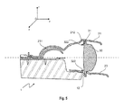
Le dissipateur thermique 10 comprend au moins un moyen de retenue de la lentille 30. Le moyen de retenue 12 est formé par une excroissance 12 qui est destiné à s'étendre dans une cavité 321 aménagée dans la lentille 30. De préférence l'excroissance 12 prend la forme d'une patte, d'un doigt, d'un pion, ou d'une tige. De préférence la section de l'excroissance est rectangulaire, carrée, hexagonale, octogonale, ou en croix, à bords saillants ou ronds. De préférence le dissipateur thermique 10 comprend deux excroissances 12.The
Selon le mode de réalisation représenté sur les
D'après une variante d'exécution, telle que représentée sur la
De préférence, la lentille 30 comprend au moins une languette inférieure 32 et au moins une cavité 321 aménagée dans la languette inférieure 32. De préférence, deux cavités 321 sont présentes dans la languette inférieure 32. Selon le mode de réalisation représenté sur les
Dans la variante illustrée à la
Un joint d'amortissement peut être placé au niveau de la surface de contact entre le dissipateur thermique 10 et la lentille 30 pour amortir les vibrations dues au moteur du véhicule.A damping gasket may be placed at the contact surface between the
Le dissipateur thermique 10 comporte des ailettes 11 d'échange thermique sur sa face inférieure.The
De préférence, le dissipateur thermique 10 comprend au moins un moyen de positionnement pour agencer le masque 20 sur le dissipateur thermique 10 lors de l'assemblage du module 1. De préférence le moyen de positionnement est une excroissance 13. De préférence l'excroissance 13 prend la forme d'une patte, d'un doigt, d'un pion, ou d'une tige. De préférence la section de l'excroissance 13 est rectangulaire, carrée, hexagonale, octogonale ou en croix, à bords saillants ou ronds. Dans le mode de réalisation représenté sur les
Le dissipateur thermique 10 comprend en outre au moins un moyen de maintien pour le masque 20 et la source lumineuse 40. De préférence le moyen de maintien est un pas de vis 17 coopérant avec une vis 50. Le dissipateur thermique 10 possède un second pas 17 de vis coopérant avec une deuxième vis 50 pour maintenir le masque.The
De préférence, le dissipateur thermique 10 comprend trois secteurs :
- un premier secteur 14 arrière sensiblement parallèle à l'axe optique,
- un deuxième secteur 16 avant sensiblement parallèle à l'axe optique ayant une altitude inférieure au premier secteur.
- un secteur intermédiaire 15 effectuant la liaison entre le premier secteur et le deuxième secteur. On entend par « sensiblement parallèle » le fait que l'angle entre l'axe optique et le premier secteur 14 et le
second secteur 16 est compris entre -10° et +10°. Dans le mode de réalisation illustré sur lesfigures 2 et3 , l'axe optique est sensiblement normal au plan intermédiaire 15 du dissipateur thermique 10. On entend par « sensiblement normal » le fait que l'angle entre l'axe optique et le plan défini par le secteur intermédiaire 15 est compris entre +-80° et + 100°.
- a
first sector 14 rear substantially parallel to the optical axis, - a
second sector 16 before substantially parallel to the optical axis having an altitude lower than the first sector. - an
intermediate sector 15 making the connection between the first sector and the second sector. The term "substantially parallel" means that the angle between the optical axis and thefirst sector 14 and thesecond sector 16 is between -10 ° and + 10 °. In the embodiment illustrated on thefigures 2 and3 the optical axis is substantially normal to theintermediate plane 15 of theheat sink 10. The term "substantially normal" means that the angle between the optical axis and the plane defined by theintermediate sector 15 is between + -80 ° and + 100 °.
De préférence, le dissipateur thermique 10 comprend des ailettes 11 sous tout ou partie du premier secteur 14 et/ou du deuxième secteur 16 et/ou du secteur intermédiaire 15.Preferably, the
Le masque 20 du module 1 comprend au moins deux parties : une coque supérieure 21 et une coque inférieure 23. Dans le mode de réalisation illustré sur les
La coque inférieure 23 comprend une surface réfléchissante 231 assurant une fonction d'éclairage et/ou de signalisation. De préférence la surface réfléchissante 231 est un réflecteur parabolique. La fonction d'éclairage et/ou de signalisation est remplie par la coopération de la surface 231 avec la source lumineuse 40. Cette dernière est fixée et positionnée sur un circuit imprimé 41, lui-même fixé sur le dissipateur thermique 10. De préférence le circuit imprimé possède des trous 411 coopérants avec des excroissances du dissipateur thermique 10. Avantageusement, les excroissances sont les excroissances 13 décrites précédemment. De préférence le circuit imprimé 41 possède des ouvertures 42 coopérant avec les vis 50. Dans le mode de réalisation représenté sur les
La source lumineuse 40 est de préférence du type diode à électroluminescence (LED), et elle est sensiblement située sur l'axe optique de la lentille 30. On entend par « sensiblement située » le fait que la distance entre la source lumineuse 40 et l'axe optique ne dépasse pas 0,5 mm.The
Cette fonction d'éclairage et/ou de signalisation peut être une fonction de signalisation de jour, communément désigné par l'appellation DRL (de l'acronyme anglo-saxon « Daytime Running Light), une fonction de signalisation communément appelée « veilleuse », une fonction de croisement, communément désignée « code », une fonction communément appelée « route ». La surface réfléchissante 231 assure ainsi la formation d'un faisceau d'éclairage et/ou de signalisation dirigé vers l'avant du véhicule.This lighting and / or signaling function may be a day signaling function, commonly referred to as the DRL (the English acronym for "Daytime Running Light"), a signaling function commonly known as a "night light", a crossover function, commonly referred to as a "code", a function commonly referred to as a "road". The reflecting
La coque inférieure 23 comprend en outre une ouverture 232 pour laisser passer la languette inférieure 32 de la lentille 30. Comme cela est plus particulièrement visible sur la
De préférence, la coque inférieure 23 comprend des trous 234 coopérant avec les moyens de positionnement 13 du dissipateur thermique 10 afin de faciliter l'assemblage du module 10. Dans le mode de réalisation représenté sur les
De préférence, la coque inférieure 23 comprend des ouvertures 235 coopérant avec les moyens de maintien du dissipateur thermique 10 pour la bonne tenue des éléments du module 1 lors de son utilisation.Preferably, the
Dans le mode de réalisation illustré sur les
La coque intermédiaire 22 du module 1 est une pièce en forme de U. De préférence, la base du U comprend des trous 221 coopérant avec les moyens de positionnement du dissipateur thermique 10 afin de faciliter l'assemblage du module 10. Dans le mode de réalisation représenté sur les
De préférence, la coque intermédiaire 22 comporte au moins un trou 222 sur au moins une branche du U coopérant avec les pions cruciformes 233 de la coque inférieure 23. De préférence, le trou 221 est présent sur chaque branche. La coque intermédiaire 22 repose sur la coque inférieure 23 et permet de positionner la coque supérieure 21.Preferably, the
De préférence, les deux branches du U viennent pincer la lentille 30. Dans le mode de réalisation illustré sur les figues 1 à 5, les extrémités des branches du U opposées à la base du U comportent une joue latérale avec une encoche coopérant avec une butée de la lentille de manière à recouvrir partiellement au moins les faces latérales de la lentille 30.Preferably, the two branches of the U come to pinch the
De préférence, la coque intermédiaire 22 est opaque pour occulter les DEL sur le côté du module. Sur l'exemple illustré sur les
La coque supérieure 21 comprend au moins une butée 212 se logeant derrière au moins une languette supérieure 31 de la lentille 30. De préférence, la coque supérieure 21 comprend au moins une butée 211 se logeant devant au moins une languette supérieure 31 de la lentille 30. De préférence, la coque supérieure 21 comprend une butée 211 et deux butées 212 parallèles disposées en quinconce venant en appui contre les bords de la languette supérieure 31 de la lentille 30. Dans le mode de réalisation préféré illustré sur les
La coque supérieure 21 repose sur la coque intermédiaire 22 et est en appui sur la languette supérieure 31 de la lentille 30 de telle sorte que la lentille 30 soit maintenue par étau entre les excroissances 12 du dissipateur thermique 10 et la coque supérieure 21 du masque 20.The
De préférence, la coque supérieure comprend des trous 214 coopérant avec les moyens de positionnement 13 du dissipateur thermique 10 afin de faciliter l'assemblage du module 10. Dans le mode de réalisation représenté sur les
La lentille 30 comporte au moins une languette inférieure 32 munie d'au moins un trou 321 coopérant avec l'excroissance 12 sur le dissipateur thermique 10 de sorte à bloquer la lentille selon au moins deux axes. La lentille 30 comporte en outre au moins une languette supérieure 31 coopérant avec au moins une butée 21X de sorte à bloquer la lentille selon un troisième axe différent des deux précédents. Dans le mode de réalisation préféré représenté sur les
De préférence, la lentille 30 comprend aussi une bordure 33 située sur la face arrière de la lentille 30 en projection orthogonale. La partie inférieure de la bordure 33 est en contact avec la coque inférieure du masque 23 afin d'éviter que la lentille 30 ne bascule vers l'arrière du module 10.Preferably, the
L'assemblage des différentes pièces décrites ci-avant pour obtenir le module d'éclairage et/ou de signalisation 1 se fait comme suit :
le circuit imprimé 41 comprenant la source lumineuse 40 est positionné à l'aide des doigts 13 sur le premier secteur 14 du dissipateur thermique 10, puis une vis 50 permet de fixer lecircuit imprimé 41 sur le dissipateur thermique 10,- la coque inférieure 23 est ensuite positionnée sur le
circuit imprimé 41 à l'aide des doigts 13 sur le premier secteur 14, - la languette inférieure 32 de la lentille 30 est insérée dans l'ouverture 232 de la coque inférieure,
- la coque intermédiaire 22 est ajoutée sur la coque inférieure 23, et positionnée grâce aux doigts 13 du dissipateur thermique 10,
- puis la coque supérieure 21 guidée aussi par les doigts 13 du dissipateur thermique vient s'encliqueter sur la languette supérieure 31 et repose sur la coque intermédiaire 22,
- l'ensemble est maintenu par vissage des vis 50 passant dans les pas de vis 17.
- the printed
circuit 41 comprising thelight source 40 is positioned with thefingers 13 on thefirst sector 14 of theheat sink 10, then ascrew 50 makes it possible to fix the printedcircuit 41 on theheat sink 10, - the
lower shell 23 is then positioned on the printedcircuit 41 with thefingers 13 on thefirst sector 14, - the
lower tongue 32 of thelens 30 is inserted into theopening 232 of the lower shell, - the
intermediate shell 22 is added to thelower shell 23, and positioned thanks to thefingers 13 of theheat sink 10, - then the
upper shell 21 also guided by thefingers 13 of the heat sink is snapped onto theupper tongue 31 and rests on theintermediate shell 22, - the assembly is held by screwing the
screws 50 passing through thethreads 17.
Dans le mode de réalisation présenté sur les
La présente invention permet en particulier de réaliser des modules et des projecteurs d'éclairage notamment pour équiper les véhicules automobiles.The present invention makes it possible in particular to produce modules and lighting projectors, in particular for equipping motor vehicles.
Enfin, il va de soi que le module d'éclairage et/ou de signalisation conforme à l'invention peut être adapté, et que les exemples que l'on vient de donner ne sont que des illustrations particulières en aucun cas limitatives des domaines d'application de l'invention. C'est ainsi qu'en particulier :
- les faisceaux générés par le ou les modules qui ont été décrits plus haut peuvent constituer des faisceaux complémentaires à des faisceaux générés par des dispositifs à lampes à incandescence ou à décharge,
- les faisceaux générés par le ou les modules qui ont été décrits plus haut peuvent constituer ensemble des faisceaux d'éclairage et/ou de signalisation.
- the beams generated by the module or modules which have been described above may constitute beams complementary to beams generated by incandescent or discharge lamp devices,
- the beams generated by the module or modules that have been described above may together constitute lighting and / or signaling beams.
Le PCB (de l'acronyme anglais « Printed Circuit Board » désignant la carte de circuit imprimé) est vissé sur le dissipateur thermique. La lentille de projection est assemblé avec l'enjoliveur formant ainsi le sous-ensemble 1. Ensuite on vient ajouter successivement la coque supérieure au sous-ensemble 1. Puis la plieuse est fixée à la coque supérieure obtenant ainsi le sous-ensemble 2. Le sous-ensemble 2 est inséré en Z sur le dissipateur thermique puis en poussant le dissipateur thermique en X pour verrouiller la lentille. On ajoute la coque supérieure à ce moment là. L'ensemble est alors vissé formant alors le module.The PCB (the acronym "Printed Circuit Board" designating the printed circuit board) is screwed on the heat sink. The projection lens is assembled with the hubcap thus forming the
La platine en aluminium pré-équipée du berceau en matériau polymère, est retournée. Les modules « kink » (de l'anglais vriller, pour désigner la coupure oblique du faisceau code) et « route » sont insérés sur la platine en X. Lors de cette opération les modules sont à l'envers. Ils sont maintenus en Z par des nervures issues de la platine en contact avec la coque supérieure. Les modules sont par la suite vissés sur la platine. Puis le module « flat » (de l'anglais plat, pour désigner la coupure plate du faisceau code) est inséré en X et clippé sur le berceau. La visse de réglage du module « flat » est alors insérée et vissée dans le module « flat ».The aluminum plate pre-equipped with the cradle made of polymer material is turned upside down. The modules "kink" (of the English vriller, to designate the oblique cut of the beam code) and "route" are inserted on the plate in X. During this operation the modules are upside down. They are maintained in Z by ribs coming from the plate in contact with the upper shell. The modules are then screwed on the plate. Then the module "flat" (flat English, to designate the flat cut of the beam code) is inserted in X and clipped on the cradle. The adjustment screw of the "flat" module is then inserted and screwed into the "flat" module.
Claims (16)
Applications Claiming Priority (4)
| Application Number | Priority Date | Filing Date | Title |
|---|---|---|---|
| FR1456239A FR3022977A1 (en) | 2014-06-30 | 2014-06-30 | LOWER MASK OF OPTICAL MODULE OF MOTOR VEHICLE |
| FR1456238A FR3022982A1 (en) | 2014-06-30 | 2014-06-30 | LOWER MASK OF OPTICAL MODULE FOR MOTOR VEHICLE |
| FR1456236A FR3022980B1 (en) | 2014-06-30 | 2014-06-30 | LENS OPTICAL MODULE FOR MOTOR VEHICLE |
| FR1456237A FR3022981A1 (en) | 2014-06-30 | 2014-06-30 | HIGHER MASK OF OPTICAL MODULE OF MOTOR VEHICLE |
Publications (2)
| Publication Number | Publication Date |
|---|---|
| EP2966344A1 true EP2966344A1 (en) | 2016-01-13 |
| EP2966344B1 EP2966344B1 (en) | 2022-01-12 |
Family
ID=53476790
Family Applications (1)
| Application Number | Title | Priority Date | Filing Date |
|---|---|---|---|
| EP15174223.6A Active EP2966344B1 (en) | 2014-06-30 | 2015-06-29 | Optical module with lens for motor vehicle projector headlamp |
Country Status (1)
| Country | Link |
|---|---|
| EP (1) | EP2966344B1 (en) |
Cited By (8)
| Publication number | Priority date | Publication date | Assignee | Title |
|---|---|---|---|---|
| ITUA20164515A1 (en) * | 2016-06-20 | 2017-12-20 | Automotive Lighting Italia Spa | COMPACT LIGHTING DEVICE FOR VEHICLES |
| EP3597986A1 (en) * | 2018-07-17 | 2020-01-22 | PSA Automobiles SA | Lighting device with floating module |
| WO2020064441A1 (en) * | 2018-09-28 | 2020-04-02 | Valeo Vision | Vehicle luminous module comprising a referencing pin with a supple portion and a stiff portion |
| EP3771861A1 (en) * | 2019-07-30 | 2021-02-03 | Valeo Vision | Lighting device |
| CN112752923A (en) * | 2018-05-03 | 2021-05-04 | 马瑞利汽车照明(德国)有限公司 | DMD-light module with clamped DMD chip |
| WO2022129392A1 (en) * | 2020-12-17 | 2022-06-23 | Valeo Vision | Automotive luminous module and method for manufacturing an automotive luminous module |
| WO2022258901A1 (en) * | 2021-06-11 | 2022-12-15 | Psa Automobiles Sa | Housing for an optical module of a lighting and/or signalling device of a motor vehicle |
| EP4065884B1 (en) * | 2019-11-26 | 2024-02-07 | Stellantis Auto SAS | Lighting unit for a motor vehicle |
Citations (11)
| Publication number | Priority date | Publication date | Assignee | Title |
|---|---|---|---|---|
| DE3516813A1 (en) | 1985-05-10 | 1986-11-13 | Hella KG Hueck & Co, 4780 Lippstadt | Dimmed vehicle headlights |
| FR2775058A1 (en) | 1999-03-26 | 1999-08-20 | Valeo Vision | Headlamp with two-part lens holder esp for motor vehicle |
| EP1770328A1 (en) * | 2005-09-30 | 2007-04-04 | Valeo Vision | Lighting and/or signaling device for a automotive vehicule incorporating a material with thermal anisotropy |
| US20070133220A1 (en) * | 2005-12-08 | 2007-06-14 | Koito Manufacturing Co., Ltd. | Vehicle lighting device |
| US20070146905A1 (en) * | 2005-12-27 | 2007-06-28 | Fujinon Corporation | Lens device and lens holding method |
| FR2895778A1 (en) * | 2006-01-05 | 2007-07-06 | Peugeot Citroen Automobiles Sa | Headlight for motor vehicle, has lens situated with respect to elliptic reflector, while object focus defined by lens meets focal spots defined by reflector, and maintained by arm integrated to support of light source |
| DE102008018478A1 (en) * | 2007-04-13 | 2008-10-16 | Koito Mfg. Co., Ltd. | vehicle light |
| EP2157364A1 (en) * | 2008-08-21 | 2010-02-24 | Koito Manufacturing Co., Ltd. | Vehicle lamp unit |
| EP2428725A2 (en) * | 2010-09-10 | 2012-03-14 | Koito Manufacturing Co., Ltd. | Vehicle headlamp |
| FR2982006A1 (en) * | 2011-09-13 | 2013-05-03 | Valeo Vision | OPTICAL MODULE WITH COMMON REFERENCE FOR LIGHTING AND / OR SIGNALING OF A MOTOR VEHICLE |
| EP2664841A2 (en) * | 2012-05-17 | 2013-11-20 | Osram Sylvania Inc. | Vehcile headlamp with both low-beam and high-beam and devoid of moving parts |
Family Cites Families (2)
| Publication number | Priority date | Publication date | Assignee | Title |
|---|---|---|---|---|
| JP6016057B2 (en) * | 2012-03-23 | 2016-10-26 | スタンレー電気株式会社 | Vehicle lighting |
| JP6441823B2 (en) * | 2014-01-22 | 2018-12-19 | 株式会社小糸製作所 | Vehicle lighting |
-
2015
- 2015-06-29 EP EP15174223.6A patent/EP2966344B1/en active Active
Patent Citations (11)
| Publication number | Priority date | Publication date | Assignee | Title |
|---|---|---|---|---|
| DE3516813A1 (en) | 1985-05-10 | 1986-11-13 | Hella KG Hueck & Co, 4780 Lippstadt | Dimmed vehicle headlights |
| FR2775058A1 (en) | 1999-03-26 | 1999-08-20 | Valeo Vision | Headlamp with two-part lens holder esp for motor vehicle |
| EP1770328A1 (en) * | 2005-09-30 | 2007-04-04 | Valeo Vision | Lighting and/or signaling device for a automotive vehicule incorporating a material with thermal anisotropy |
| US20070133220A1 (en) * | 2005-12-08 | 2007-06-14 | Koito Manufacturing Co., Ltd. | Vehicle lighting device |
| US20070146905A1 (en) * | 2005-12-27 | 2007-06-28 | Fujinon Corporation | Lens device and lens holding method |
| FR2895778A1 (en) * | 2006-01-05 | 2007-07-06 | Peugeot Citroen Automobiles Sa | Headlight for motor vehicle, has lens situated with respect to elliptic reflector, while object focus defined by lens meets focal spots defined by reflector, and maintained by arm integrated to support of light source |
| DE102008018478A1 (en) * | 2007-04-13 | 2008-10-16 | Koito Mfg. Co., Ltd. | vehicle light |
| EP2157364A1 (en) * | 2008-08-21 | 2010-02-24 | Koito Manufacturing Co., Ltd. | Vehicle lamp unit |
| EP2428725A2 (en) * | 2010-09-10 | 2012-03-14 | Koito Manufacturing Co., Ltd. | Vehicle headlamp |
| FR2982006A1 (en) * | 2011-09-13 | 2013-05-03 | Valeo Vision | OPTICAL MODULE WITH COMMON REFERENCE FOR LIGHTING AND / OR SIGNALING OF A MOTOR VEHICLE |
| EP2664841A2 (en) * | 2012-05-17 | 2013-11-20 | Osram Sylvania Inc. | Vehcile headlamp with both low-beam and high-beam and devoid of moving parts |
Cited By (15)
| Publication number | Priority date | Publication date | Assignee | Title |
|---|---|---|---|---|
| EP3260764A1 (en) * | 2016-06-20 | 2017-12-27 | Automotive Lighting Italia S.p.A. | Compact lighting device for vehicles |
| ITUA20164515A1 (en) * | 2016-06-20 | 2017-12-20 | Automotive Lighting Italia Spa | COMPACT LIGHTING DEVICE FOR VEHICLES |
| CN112752923B (en) * | 2018-05-03 | 2022-12-02 | 马瑞利汽车照明(德国)有限公司 | DMD-light module with clamped DMD chip |
| CN112752923A (en) * | 2018-05-03 | 2021-05-04 | 马瑞利汽车照明(德国)有限公司 | DMD-light module with clamped DMD chip |
| EP3597986A1 (en) * | 2018-07-17 | 2020-01-22 | PSA Automobiles SA | Lighting device with floating module |
| FR3084137A1 (en) * | 2018-07-17 | 2020-01-24 | Psa Automobiles Sa | FLOATING MODULE LIGHTING DEVICE |
| WO2020064441A1 (en) * | 2018-09-28 | 2020-04-02 | Valeo Vision | Vehicle luminous module comprising a referencing pin with a supple portion and a stiff portion |
| FR3086734A1 (en) * | 2018-09-28 | 2020-04-03 | Valeo Vision | VEHICLE LIGHT MODULE COMPRISING A REFERENCING PIONE WITH A FLEXIBLE PART AND A RIGID PART |
| US11668446B2 (en) | 2018-09-28 | 2023-06-06 | Valeo Vision | Vehicle light module comprising a locating pin with a flexible part and a rigid part |
| EP3771861A1 (en) * | 2019-07-30 | 2021-02-03 | Valeo Vision | Lighting device |
| FR3099545A1 (en) * | 2019-07-30 | 2021-02-05 | Valeo Vision | Luminous device |
| EP4065884B1 (en) * | 2019-11-26 | 2024-02-07 | Stellantis Auto SAS | Lighting unit for a motor vehicle |
| WO2022129392A1 (en) * | 2020-12-17 | 2022-06-23 | Valeo Vision | Automotive luminous module and method for manufacturing an automotive luminous module |
| WO2022258901A1 (en) * | 2021-06-11 | 2022-12-15 | Psa Automobiles Sa | Housing for an optical module of a lighting and/or signalling device of a motor vehicle |
| FR3123963A1 (en) * | 2021-06-11 | 2022-12-16 | Psa Automobiles Sa | Optical module housing of a motor vehicle lighting and/or signaling device. |
Also Published As
| Publication number | Publication date |
|---|---|
| EP2966344B1 (en) | 2022-01-12 |
Similar Documents
| Publication | Publication Date | Title |
|---|---|---|
| EP2966344B1 (en) | Optical module with lens for motor vehicle projector headlamp | |
| EP2366938B1 (en) | Vehicle lighting device | |
| EP3853517B1 (en) | Light system for a lighting and/or signalling device of a motor vehicle | |
| CA2810700C (en) | Optical module of an illuminating and/or signalling device of a motor vehicle | |
| EP2921772B1 (en) | Light module of a motor vehicle | |
| FR2865524A1 (en) | Lighting unit for vehicle headlight, has radiating panel in form of ceramic or metallic plate including upper surface fixed with electroluminescent diode unit, and LED module, reflector and lens positioned with respect to base | |
| FR2982006A1 (en) | OPTICAL MODULE WITH COMMON REFERENCE FOR LIGHTING AND / OR SIGNALING OF A MOTOR VEHICLE | |
| FR2858044A1 (en) | Light e.g. headlight, for e.g. automobile, has photo-emissive unit to emit light from region having linear limit, and lens to project shape of light region for forming line of cut that forms limit between bright and dark regions | |
| FR3002794A1 (en) | LIGHTING AND / OR SIGNALING DEVICE FOR A MOTOR VEHICLE HAVING A LIGHT GUIDE | |
| EP3128230B1 (en) | Heat sink for motor vehicle optical module | |
| EP3489576A1 (en) | Light module for lighting and/or signalling of a motor vehicle | |
| FR2994788A1 (en) | LIGHTING MODULE COMPRISING A REMOTELY REMAINING CONTROL DEVICE ON A SUPPORT | |
| FR3022980A1 (en) | LENS OPTICAL MODULE FOR MOTOR VEHICLE | |
| FR3022974A1 (en) | LIGHTING MODULE FOR AUTOMOTIVE PROJECTOR WITH POSITIONING BETWEEN REFLECTOR AND LENS | |
| EP3299710A1 (en) | Luminous module and luminous device for motor vehicle comprising such a luminous module | |
| EP3290791B1 (en) | Motor vehicle light module with cooling member | |
| EP3299702A1 (en) | Luminous optical module of a motor vehicle | |
| FR2948616A1 (en) | LIGHTING DEVICE FOR MOTOR VEHICLE | |
| FR3056698B1 (en) | LUMINOUS MODULE FOR MOTOR VEHICLE | |
| FR3022977A1 (en) | LOWER MASK OF OPTICAL MODULE OF MOTOR VEHICLE | |
| FR2948617A1 (en) | LIGHTING DEVICE FOR MOTOR VEHICLE | |
| EP2947380B1 (en) | Light-emitting module with light-emitting diode and screen | |
| EP3884206A1 (en) | Multi-functional light module provided with two flat light guides | |
| EP3486554A1 (en) | Light module for vehicle headlight | |
| FR3088869A1 (en) | Device for pre-positioning and holding an element on a box |
Legal Events
| Date | Code | Title | Description |
|---|---|---|---|
| PUAI | Public reference made under article 153(3) epc to a published international application that has entered the european phase |
Free format text: ORIGINAL CODE: 0009012 |
|
| AK | Designated contracting states |
Kind code of ref document: A1 Designated state(s): AL AT BE BG CH CY CZ DE DK EE ES FI FR GB GR HR HU IE IS IT LI LT LU LV MC MK MT NL NO PL PT RO RS SE SI SK SM TR |
|
| AX | Request for extension of the european patent |
Extension state: BA ME |
|
| 17P | Request for examination filed |
Effective date: 20160713 |
|
| RBV | Designated contracting states (corrected) |
Designated state(s): AL AT BE BG CH CY CZ DE DK EE ES FI FR GB GR HR HU IE IS IT LI LT LU LV MC MK MT NL NO PL PT RO RS SE SI SK SM TR |
|
| STAA | Information on the status of an ep patent application or granted ep patent |
Free format text: STATUS: EXAMINATION IS IN PROGRESS |
|
| 17Q | First examination report despatched |
Effective date: 20161216 |
|
| STAA | Information on the status of an ep patent application or granted ep patent |
Free format text: STATUS: EXAMINATION IS IN PROGRESS |
|
| REG | Reference to a national code |
Ref country code: DE Ref legal event code: R079 Ref document number: 602015076386 Country of ref document: DE Free format text: PREVIOUS MAIN CLASS: F21S0008100000 Ipc: F21S0041100000 |
|
| GRAP | Despatch of communication of intention to grant a patent |
Free format text: ORIGINAL CODE: EPIDOSNIGR1 |
|
| STAA | Information on the status of an ep patent application or granted ep patent |
Free format text: STATUS: GRANT OF PATENT IS INTENDED |
|
| RIC1 | Information provided on ipc code assigned before grant |
Ipc: F21S 41/10 20180101AFI20210622BHEP Ipc: F21S 41/148 20180101ALI20210622BHEP Ipc: F21S 41/19 20180101ALI20210622BHEP Ipc: F21S 41/29 20180101ALI20210622BHEP Ipc: F21S 41/39 20180101ALI20210622BHEP Ipc: F21S 41/50 20180101ALI20210622BHEP Ipc: F21S 41/55 20180101ALI20210622BHEP Ipc: F21S 45/48 20180101ALI20210622BHEP Ipc: F21S 45/49 20180101ALI20210622BHEP |
|
| INTG | Intention to grant announced |
Effective date: 20210723 |
|
| GRAS | Grant fee paid |
Free format text: ORIGINAL CODE: EPIDOSNIGR3 |
|
| GRAA | (expected) grant |
Free format text: ORIGINAL CODE: 0009210 |
|
| STAA | Information on the status of an ep patent application or granted ep patent |
Free format text: STATUS: THE PATENT HAS BEEN GRANTED |
|
| AK | Designated contracting states |
Kind code of ref document: B1 Designated state(s): AL AT BE BG CH CY CZ DE DK EE ES FI FR GB GR HR HU IE IS IT LI LT LU LV MC MK MT NL NO PL PT RO RS SE SI SK SM TR |
|
| REG | Reference to a national code |
Ref country code: GB Ref legal event code: FG4D Free format text: NOT ENGLISH |
|
| REG | Reference to a national code |
Ref country code: CH Ref legal event code: EP |
|
| REG | Reference to a national code |
Ref country code: DE Ref legal event code: R096 Ref document number: 602015076386 Country of ref document: DE |
|
| REG | Reference to a national code |
Ref country code: IE Ref legal event code: FG4D Free format text: LANGUAGE OF EP DOCUMENT: FRENCH |
|
| REG | Reference to a national code |
Ref country code: AT Ref legal event code: REF Ref document number: 1462617 Country of ref document: AT Kind code of ref document: T Effective date: 20220215 |
|
| REG | Reference to a national code |
Ref country code: LT Ref legal event code: MG9D |
|
| REG | Reference to a national code |
Ref country code: NL Ref legal event code: MP Effective date: 20220112 |
|
| REG | Reference to a national code |
Ref country code: AT Ref legal event code: MK05 Ref document number: 1462617 Country of ref document: AT Kind code of ref document: T Effective date: 20220112 |
|
| PG25 | Lapsed in a contracting state [announced via postgrant information from national office to epo] |
Ref country code: NL Free format text: LAPSE BECAUSE OF FAILURE TO SUBMIT A TRANSLATION OF THE DESCRIPTION OR TO PAY THE FEE WITHIN THE PRESCRIBED TIME-LIMIT Effective date: 20220112 |
|
| PG25 | Lapsed in a contracting state [announced via postgrant information from national office to epo] |
Ref country code: SE Free format text: LAPSE BECAUSE OF FAILURE TO SUBMIT A TRANSLATION OF THE DESCRIPTION OR TO PAY THE FEE WITHIN THE PRESCRIBED TIME-LIMIT Effective date: 20220112 Ref country code: RS Free format text: LAPSE BECAUSE OF FAILURE TO SUBMIT A TRANSLATION OF THE DESCRIPTION OR TO PAY THE FEE WITHIN THE PRESCRIBED TIME-LIMIT Effective date: 20220112 Ref country code: PT Free format text: LAPSE BECAUSE OF FAILURE TO SUBMIT A TRANSLATION OF THE DESCRIPTION OR TO PAY THE FEE WITHIN THE PRESCRIBED TIME-LIMIT Effective date: 20220512 Ref country code: NO Free format text: LAPSE BECAUSE OF FAILURE TO SUBMIT A TRANSLATION OF THE DESCRIPTION OR TO PAY THE FEE WITHIN THE PRESCRIBED TIME-LIMIT Effective date: 20220412 Ref country code: LT Free format text: LAPSE BECAUSE OF FAILURE TO SUBMIT A TRANSLATION OF THE DESCRIPTION OR TO PAY THE FEE WITHIN THE PRESCRIBED TIME-LIMIT Effective date: 20220112 Ref country code: HR Free format text: LAPSE BECAUSE OF FAILURE TO SUBMIT A TRANSLATION OF THE DESCRIPTION OR TO PAY THE FEE WITHIN THE PRESCRIBED TIME-LIMIT Effective date: 20220112 Ref country code: ES Free format text: LAPSE BECAUSE OF FAILURE TO SUBMIT A TRANSLATION OF THE DESCRIPTION OR TO PAY THE FEE WITHIN THE PRESCRIBED TIME-LIMIT Effective date: 20220112 Ref country code: BG Free format text: LAPSE BECAUSE OF FAILURE TO SUBMIT A TRANSLATION OF THE DESCRIPTION OR TO PAY THE FEE WITHIN THE PRESCRIBED TIME-LIMIT Effective date: 20220412 |
|
| PG25 | Lapsed in a contracting state [announced via postgrant information from national office to epo] |
Ref country code: PL Free format text: LAPSE BECAUSE OF FAILURE TO SUBMIT A TRANSLATION OF THE DESCRIPTION OR TO PAY THE FEE WITHIN THE PRESCRIBED TIME-LIMIT Effective date: 20220112 Ref country code: LV Free format text: LAPSE BECAUSE OF FAILURE TO SUBMIT A TRANSLATION OF THE DESCRIPTION OR TO PAY THE FEE WITHIN THE PRESCRIBED TIME-LIMIT Effective date: 20220112 Ref country code: GR Free format text: LAPSE BECAUSE OF FAILURE TO SUBMIT A TRANSLATION OF THE DESCRIPTION OR TO PAY THE FEE WITHIN THE PRESCRIBED TIME-LIMIT Effective date: 20220413 Ref country code: FI Free format text: LAPSE BECAUSE OF FAILURE TO SUBMIT A TRANSLATION OF THE DESCRIPTION OR TO PAY THE FEE WITHIN THE PRESCRIBED TIME-LIMIT Effective date: 20220112 Ref country code: AT Free format text: LAPSE BECAUSE OF FAILURE TO SUBMIT A TRANSLATION OF THE DESCRIPTION OR TO PAY THE FEE WITHIN THE PRESCRIBED TIME-LIMIT Effective date: 20220112 |
|
| PG25 | Lapsed in a contracting state [announced via postgrant information from national office to epo] |
Ref country code: IS Free format text: LAPSE BECAUSE OF FAILURE TO SUBMIT A TRANSLATION OF THE DESCRIPTION OR TO PAY THE FEE WITHIN THE PRESCRIBED TIME-LIMIT Effective date: 20220512 |
|
| REG | Reference to a national code |
Ref country code: DE Ref legal event code: R097 Ref document number: 602015076386 Country of ref document: DE |
|
| PG25 | Lapsed in a contracting state [announced via postgrant information from national office to epo] |
Ref country code: SM Free format text: LAPSE BECAUSE OF FAILURE TO SUBMIT A TRANSLATION OF THE DESCRIPTION OR TO PAY THE FEE WITHIN THE PRESCRIBED TIME-LIMIT Effective date: 20220112 Ref country code: SK Free format text: LAPSE BECAUSE OF FAILURE TO SUBMIT A TRANSLATION OF THE DESCRIPTION OR TO PAY THE FEE WITHIN THE PRESCRIBED TIME-LIMIT Effective date: 20220112 Ref country code: RO Free format text: LAPSE BECAUSE OF FAILURE TO SUBMIT A TRANSLATION OF THE DESCRIPTION OR TO PAY THE FEE WITHIN THE PRESCRIBED TIME-LIMIT Effective date: 20220112 Ref country code: EE Free format text: LAPSE BECAUSE OF FAILURE TO SUBMIT A TRANSLATION OF THE DESCRIPTION OR TO PAY THE FEE WITHIN THE PRESCRIBED TIME-LIMIT Effective date: 20220112 Ref country code: DK Free format text: LAPSE BECAUSE OF FAILURE TO SUBMIT A TRANSLATION OF THE DESCRIPTION OR TO PAY THE FEE WITHIN THE PRESCRIBED TIME-LIMIT Effective date: 20220112 Ref country code: CZ Free format text: LAPSE BECAUSE OF FAILURE TO SUBMIT A TRANSLATION OF THE DESCRIPTION OR TO PAY THE FEE WITHIN THE PRESCRIBED TIME-LIMIT Effective date: 20220112 |
|
| PLBE | No opposition filed within time limit |
Free format text: ORIGINAL CODE: 0009261 |
|
| STAA | Information on the status of an ep patent application or granted ep patent |
Free format text: STATUS: NO OPPOSITION FILED WITHIN TIME LIMIT |
|
| PG25 | Lapsed in a contracting state [announced via postgrant information from national office to epo] |
Ref country code: AL Free format text: LAPSE BECAUSE OF FAILURE TO SUBMIT A TRANSLATION OF THE DESCRIPTION OR TO PAY THE FEE WITHIN THE PRESCRIBED TIME-LIMIT Effective date: 20220112 |
|
| 26N | No opposition filed |
Effective date: 20221013 |
|
| PG25 | Lapsed in a contracting state [announced via postgrant information from national office to epo] |
Ref country code: MC Free format text: LAPSE BECAUSE OF FAILURE TO SUBMIT A TRANSLATION OF THE DESCRIPTION OR TO PAY THE FEE WITHIN THE PRESCRIBED TIME-LIMIT Effective date: 20220112 |
|
| REG | Reference to a national code |
Ref country code: CH Ref legal event code: PL |
|
| REG | Reference to a national code |
Ref country code: BE Ref legal event code: MM Effective date: 20220630 |
|
| PG25 | Lapsed in a contracting state [announced via postgrant information from national office to epo] |
Ref country code: SI Free format text: LAPSE BECAUSE OF FAILURE TO SUBMIT A TRANSLATION OF THE DESCRIPTION OR TO PAY THE FEE WITHIN THE PRESCRIBED TIME-LIMIT Effective date: 20220112 |
|
| GBPC | Gb: european patent ceased through non-payment of renewal fee |
Effective date: 20220629 |
|
| PG25 | Lapsed in a contracting state [announced via postgrant information from national office to epo] |
Ref country code: LU Free format text: LAPSE BECAUSE OF NON-PAYMENT OF DUE FEES Effective date: 20220629 Ref country code: LI Free format text: LAPSE BECAUSE OF NON-PAYMENT OF DUE FEES Effective date: 20220630 Ref country code: IE Free format text: LAPSE BECAUSE OF NON-PAYMENT OF DUE FEES Effective date: 20220629 Ref country code: CH Free format text: LAPSE BECAUSE OF NON-PAYMENT OF DUE FEES Effective date: 20220630 |
|
| PG25 | Lapsed in a contracting state [announced via postgrant information from national office to epo] |
Ref country code: GB Free format text: LAPSE BECAUSE OF NON-PAYMENT OF DUE FEES Effective date: 20220629 Ref country code: BE Free format text: LAPSE BECAUSE OF NON-PAYMENT OF DUE FEES Effective date: 20220630 |
|
| P01 | Opt-out of the competence of the unified patent court (upc) registered |
Effective date: 20230528 |
|
| PG25 | Lapsed in a contracting state [announced via postgrant information from national office to epo] |
Ref country code: IT Free format text: LAPSE BECAUSE OF FAILURE TO SUBMIT A TRANSLATION OF THE DESCRIPTION OR TO PAY THE FEE WITHIN THE PRESCRIBED TIME-LIMIT Effective date: 20220112 |
|
| PGFP | Annual fee paid to national office [announced via postgrant information from national office to epo] |
Ref country code: DE Payment date: 20230613 Year of fee payment: 9 |
|
| PG25 | Lapsed in a contracting state [announced via postgrant information from national office to epo] |
Ref country code: HU Free format text: LAPSE BECAUSE OF FAILURE TO SUBMIT A TRANSLATION OF THE DESCRIPTION OR TO PAY THE FEE WITHIN THE PRESCRIBED TIME-LIMIT; INVALID AB INITIO Effective date: 20150629 |
|
| PG25 | Lapsed in a contracting state [announced via postgrant information from national office to epo] |
Ref country code: MK Free format text: LAPSE BECAUSE OF FAILURE TO SUBMIT A TRANSLATION OF THE DESCRIPTION OR TO PAY THE FEE WITHIN THE PRESCRIBED TIME-LIMIT Effective date: 20220112 Ref country code: CY Free format text: LAPSE BECAUSE OF FAILURE TO SUBMIT A TRANSLATION OF THE DESCRIPTION OR TO PAY THE FEE WITHIN THE PRESCRIBED TIME-LIMIT Effective date: 20220112 |
|
| PG25 | Lapsed in a contracting state [announced via postgrant information from national office to epo] |
Ref country code: TR Free format text: LAPSE BECAUSE OF FAILURE TO SUBMIT A TRANSLATION OF THE DESCRIPTION OR TO PAY THE FEE WITHIN THE PRESCRIBED TIME-LIMIT Effective date: 20220112 |
|
| PGFP | Annual fee paid to national office [announced via postgrant information from national office to epo] |
Ref country code: FR Payment date: 20240625 Year of fee payment: 10 |
|
| PG25 | Lapsed in a contracting state [announced via postgrant information from national office to epo] |
Ref country code: MT Free format text: LAPSE BECAUSE OF FAILURE TO SUBMIT A TRANSLATION OF THE DESCRIPTION OR TO PAY THE FEE WITHIN THE PRESCRIBED TIME-LIMIT Effective date: 20220112 |