EP2966020A1 - Yarn accumulating device, yarn winding unit, and yarn winding machine - Google Patents
Yarn accumulating device, yarn winding unit, and yarn winding machine Download PDFInfo
- Publication number
- EP2966020A1 EP2966020A1 EP15169263.9A EP15169263A EP2966020A1 EP 2966020 A1 EP2966020 A1 EP 2966020A1 EP 15169263 A EP15169263 A EP 15169263A EP 2966020 A1 EP2966020 A1 EP 2966020A1
- Authority
- EP
- European Patent Office
- Prior art keywords
- yarn
- section
- yarn accumulating
- stator
- winding
- Prior art date
- Legal status (The legal status is an assumption and is not a legal conclusion. Google has not performed a legal analysis and makes no representation as to the accuracy of the status listed.)
- Granted
Links
Images



Classifications
-
- B—PERFORMING OPERATIONS; TRANSPORTING
- B65—CONVEYING; PACKING; STORING; HANDLING THIN OR FILAMENTARY MATERIAL
- B65H—HANDLING THIN OR FILAMENTARY MATERIAL, e.g. SHEETS, WEBS, CABLES
- B65H51/00—Forwarding filamentary material
- B65H51/20—Devices for temporarily storing filamentary material during forwarding, e.g. for buffer storage
- B65H51/22—Reels or cages, e.g. cylindrical, with storing and forwarding surfaces provided by rollers or bars
-
- B—PERFORMING OPERATIONS; TRANSPORTING
- B65—CONVEYING; PACKING; STORING; HANDLING THIN OR FILAMENTARY MATERIAL
- B65H—HANDLING THIN OR FILAMENTARY MATERIAL, e.g. SHEETS, WEBS, CABLES
- B65H2701/00—Handled material; Storage means
- B65H2701/30—Handled filamentary material
- B65H2701/31—Textiles threads or artificial strands of filaments
Definitions
- the present invention relates to a yarn accumulating device, a yarn winding unit, and a yarn winding machine.
- a yarn winding machine such as a spinning machine includes a yarn accumulating device adapted to wind a yarn around a periphery of a rotating yarn accumulating roller to temporarily accumulate the yarn.
- the yarn accumulating device described in Japanese Unexamined Patent Publication No. 2010-77576 includes a yarn accumulating roller around which the yarn is wound, and a yarn hooking member adapted to wind the yarn around the yarn accumulating roller.
- the yarn accumulating roller is attached to a drive shaft of an electric motor to be rotated by the electric motor.
- a permanent magnet is attached to one of the yarn hooking member and the yarn accumulating roller, and a magnetic hysteresis material is attached to the other of the yarn hooking member and the yarn accumulating roller.
- a resistance torque against relative rotation of the yarn hooking member with respect to the yarn accumulating roller is thereby generated, and the yarn hooking member integrally rotates with the yarn accumulating roller by such a resistance torque.
- the yarn hooking member relatively rotates with respect to the yarn accumulating roller.
- the rotation resistance of the yarn hooking member with respect to the yarn accumulating roller is manually adjusted to adjust tension to be applied to the yarn.
- the rotation resistance needs to be adjusted for each spinning unit, which is a very cumbersome task.
- a yarn accumulating device includes a yarn accumulating roller around which a yarn is wound; a yarn guiding member rotatable with respect to the yarn accumulating roller; a first driving section adapted to rotatably drive the yarn accumulating roller; and a second driving section adapted to rotatably drive the yarn guiding member, wherein the yarn accumulating roller includes a yarn accumulating section around which the yarn is wound, and a supporting section arranged on an inner side of the yarn accumulating section; the first driving section includes a first stator located on the inner side of the yarn accumulating section and arranged so as to extend along a rotation axis direction of the yarn accumulating roller and to be coaxial with a rotation axis, and a first rotor fixed on the inner side of the yarn accumulating section at a position surrounding the first stator, the second driving section includes a second stator located on the inner side of the yarn accumulating section and fixed to a distal end of the first stator, and
- the first driving section is configured such that the first rotor rotates around the first stator located on the inner side of the yarn accumulating section.
- the first driving section is a so-called outer rotor type motor.
- the first stator that does not rotate even if the yarn accumulating roller rotates exists on the inner side of the yarn accumulating section.
- the yarn guiding member is rotatably driven coaxially with the rotation axis of the yarn accumulating roller. Therefore, the yarn accumulating roller and the yarn hooking member can be driven independently from each other in the yarn accumulating device.
- the yarn accumulating device has at least two bearing members that enable the yarn accumulating roller to freely rotate with respect to the first stator arranged between the first stator and the supporting section. Thus, the yarn accumulating roller can be stably rotated.
- the first driving section may be a stepping motor.
- the first driving section thus can be controlled at a constant torque, and the yarn accumulating roller can be stably rotated. As a result, the yarn accumulating device can stably accumulate the yarn.
- the yarn accumulating device includes a control section adapted to control the drive of the first driving section, wherein the control section may stop the drive of the first driving section when the first driving section steps out.
- the control section may stop the drive of the first driving section when the first driving section steps out.
- the yarn accumulating device may stop the drive of the first driving section when the step-out of the first driving section is detected.
- the step-out of the first driving section can be more reliably detected.
- the second driving section may rotate the yarn guiding member at a speed greater than or equal to a rotation speed of the yarn accumulating roller.
- the control section controls the drive of the second driving section.
- time may be required until the rotation speed of the first driving section reaches a predetermined speed. In this case, the tension of the yarn is low, and thus the yarn Y may be loosely wound around the yarn accumulating roller.
- the rotation speed of the yarn guiding member is set higher than the rotation speed of the yarn accumulating roller at the start of the winding of the yarn around the yarn accumulating roller, so that the yarn can be wound around the yarn accumulating roller at high speed by the yarn guiding member and the tension can be applied to the yarn.
- the yarn can be suppressed from being loosely wound around the yarn accumulating roller.
- a yarn winding unit includes the above yarn accumulating device; a spinning device adapted to produce the yarn to be wound around the yarn accumulating roller of the yarn accumulating device; and a winding device adapted to wind the yarn pulled out from the yarn accumulating roller into a package. Furthermore, the yarn winding unit includes a unit control section adapted to stop the operation of the spinning device when the first driving section steps out, wherein the control section is the unit control section.
- the yarn winding unit includes the above yarn accumulating device, the spun yarn can be stably pulled out from the spinning device and the tension of the yarn in the winding device can be adjusted to prevent the fluctuation of the tension of the yarn in the winding device. Therefore, the quality of the package can be improved in the yarn winding unit.
- the yarn winding unit may include a unit control section adapted to stop the operation of the spinning device when the first driving section steps out.
- a unit control section adapted to stop the operation of the spinning device when the first driving section steps out.
- the yarn winding unit may include a notifying section adapted to notify the step-out of the first driving section when the first driving section steps out.
- the yarn winding unit including the yarn accumulating device in which the step-out has occurred can be notified to the operator.
- the unit control section may control the drive of the second driving section during the winding of the yarn in the winding device to change a rotation speed of the yarn guiding member.
- the winding tension is set high when the winding diameter is small and the winding tension is set lower as the winding diameter becomes larger to obtain a satisfactory package shape. Therefore, the rotation of the yarn hooking member is changed to set the tension high at the start of the winding of the package and to set the tension low at the end of the winding to form a satisfactory package.
- a yarn winding machine includes a plurality of the above yarn winding units; and a setting section adapted to carry out setting of tension of the yarn wound in the winding device of each of the plurality of yarn winding units.
- the setting of the tension of the yarn wound in the winding device of each winding unit that is, the setting of the second driving section adapted to drive the yarn hooking member can be carried out all at once in the setting section.
- the tension can be easily set in the yarn winding machine.
- the yarn accumulating roller can be stably rotated.
- a spinning machine (yarn winding machine) 1 includes a plurality of spinning units (yarn winding units) 2, a yarn joining cart 3, a first end frame 4, a second end frame 5, and a machine controller (setting section) 6.
- the plurality of spinning units 2 are arranged in a line, and each spinning unit 2 produces a spun yarn Y and winds the spun yarn Y into a package P.
- the yarn joining cart 3 performs a yarn joining operation in the spinning unit 2 in which the spun yarn Y is cut.
- the first end frame 4 accommodates an air supply source for generating a whirling airflow at each section of the spinning unit 2 and/or a suction source or the like for generating a suction flow at each section of the spinning unit 2.
- the second end frame 5 accommodates a motor and the like for supplying power to each section of the spinning unit 2.
- the machine controller 6 controls the operation of the entire spinning machine 1.
- a side on which the spun yarn Y is produced is referred to as upstream and a side on which the spun yarn Y is wound is referred to as downstream.
- a side on which the yarn path is located with respect to the yarn joining cart 3 is referred to as a front side, and a side opposite to the front side is referred to as a back side.
- a work passage (not illustrated) extending in a direction in which the plurality of spinning units 2 are arranged is provided on the front side of the spinning machine 1. The operator thus can perform operation, monitoring, and the like of each spinning unit 2 from the work passage.
- each spinning unit 2 includes a draft device 7, a pneumatic spinning device 8, a yarn defect detecting section 9, a tension sensor 10, a yarn accumulating device 11, a waxing device 12, and a winding device 13 in this order from the upstream.
- These devices are directly or indirectly supported by a machine frame 14 such that the upstream is an upper side in a machine height direction (i.e., downstream is a lower side in the machine height direction).
- the draft device 7 drafts a fiber bundle S.
- the draft device 7 includes a back roller pair 7a, a third roller pair 7b, a middle roller pair 7d provided with an apron belt 7c on each roller, and a front roller pair 7e in this order from the upstream (the side from which the fiber bundle S is supplied in the feeding path of the fiber bundle S).
- the pneumatic spinning device 8 applies twists to the fiber bundle S drafted by the draft device 7 using the whirling airflow to produce the spun yarn Y.
- the yarn defect detecting section 9 is adapted to monitor the travelling spun yarn Y between the pneumatic spinning device 8 and the yarn accumulating device 11. When the yarn defect is detected, the yarn defect detecting section 9 transmits a yarn defect detection signal to a unit controller (control section) 15.
- the yarn defect detecting section 9 detects, for example, a thickness abnormality of the spun yarn Y and/or foreign substance contained in the spun yarn Y as the yarn defect.
- the tension sensor 10 is adapted to measure tension of the travelling spun yarn Y between the pneumatic spinning device 8 and the yarn accumulating device 11, and transmit a tension measurement signal to the unit control section 15.
- the yarn accumulating device 11 is adapted to accumulate the travelling spun yarn Y between the pneumatic spinning device 8 and the winding device 13.
- the yarn accumulating device 11 has a function of stably pulling out the spun yarn Y from the pneumatic spinning device 8, a function of accumulating the spun yarn Y fed from the pneumatic spinning device 8 to prevent the spun yarn Y from slackening during the yarn joining operation by the yarn joining cart 3 or the like, and a function of adjusting the tension of the spun yarn Y at the winding device 13 to prevent a fluctuation in the tension of the spun yarn Y at the winding device 13 from being transmitted towards the pneumatic spinning device 8.
- the waxing device 12 is adapted to apply wax to the travelling spun yarn Y between the yarn accumulating device 11 and the winding device 13.
- the unit control section 15 is provided for each spinning unit 2, and is adapted to control an operation of the spinning unit 2.
- the unit control section 15 is controlled by the machine controller 6.
- the winding device 13 is adapted to wind the spun yarn Y produced by the pneumatic spinning device 8 to form the package P.
- the winding device 13 includes a cradle arm 21, a winding drum 22, and a traverse device 23.
- the cradle arm 21 is swingably supported by a supporting shaft 24, and causes a surface of the rotatably supported bobbin B or a surface of the package P to make contact with a surface of the winding drum 22 at an appropriate pressure.
- the winding drum 22 is driven by an electric motor (not illustrated) provided in each spinning unit 2 to rotate the bobbin B or the package P making contact with the winding drum 22.
- the traverse device 23 is driven by a shaft 25 shared among the plurality of spinning units 2, and traverses the spun yarn Y over a prescribed width with respect to the rotating bobbin B or the package P.
- the yarn joining cart 3 travels to the spinning unit 2 in which the spun yarn Y is disconnected to perform the yarn joining operation in the target spinning unit 2.
- the yarn joining cart 3 includes a splicer 26, a suction pipe 27, and a suction mouth 28.
- the suction pipe 27 is swingably supported by a supporting shaft 31, and is adapted to suck and catch a yarn end of the spun yarn Y from the pneumatic spinning device 8 to guide the yarn end to the splicer 26.
- the suction mouth 28 is swingably supported by a supporting shaft 32, and is adapted to suck and catch a yarn end of the spun yarn Y from the winding device 13 to guide the yarn end to the splicer 26.
- the splicer 26 joins the guided yarn ends.
- a touch panel display (notifying section) D is connected to the machine controller 6.
- the touch panel display D displays information related to various types of settings of the spinning machine 1 and information related to an operation state of the spinning machine 1, and receives an input from the operator.
- the touch panel display D functions as a display section and an input section.
- the touch panel display D displays a display screen based on display information output from the machine controller 6.
- the touch panel display D outputs operation information to the machine controller 6 when the display screen is operated by the operator.
- the yarn accumulating device 11 includes a yarn accumulating roller 40, a first motor (first driving section) 50, a yarn hooking member (yarn guiding member) 60, and a second motor (second driving section) 70.
- the yarn accumulating roller 40 includes a yarn accumulating section 41 and a supporting section 42.
- the spun yarn Y is wound around an outer peripheral surface of the yarn accumulating section 41.
- the yarn accumulating section 41 has a substantially cylindrical shape, and has a basal end portion 41a on a winding start side of the spun yarn Y and a distal end portion 41b on a side from which the spun yarn Y is unwound.
- the basal end portion 41a includes a basal end tapered portion 43.
- the basal end tapered portion 43 is formed such that the outer diameter becomes greater from the basal end portion 41a towards the upstream.
- the distal end portion 41b includes a distal end tapered portion 44.
- the distal end tapered portion 44 is formed such that the outer diameter becomes greater from the distal end portion 41b towards the downstream.
- the outer peripheral surface of the portion between the basal end portion 41a and the distal end portion 41b has the same diameter, as illustrated in FIG. 3 , for example.
- the outer peripheral surface of the relevant portion may be provided with a surface having at least one tapered angle.
- a slit and the like may be formed on the surface of the yarn accumulating section 41.
- the supporting section 42 is arranged on the inner side of the yarn accumulating section 41.
- the supporting section 42 is located at a substantially central part in the rotation axis direction (hereinafter, simply referred to as rotation axis direction) of the yarn accumulating section 41, and projects further towards the inner side than an inner surface 41s of the yarn accumulating section 41.
- the yarn accumulating roller 40 has a substantially H-shaped cross-section along the rotation axis direction.
- the supporting section 42 is provided with a circular hole 42h. The center of the hole 42h coincides with the rotation axis of the yarn accumulating roller 40.
- a first hollow region A1 close to the basal end portion 41a and a second hollow region A2 close to the distal end portion 41b are partitioned inside the yarn accumulating section 41 by the supporting section 42.
- the supporting section 42 is supported by a first stator 51, to be described later.
- the first motor 50 rotates the yarn accumulating roller 40.
- the first motor 50 is an outer rotor type stepping motor.
- the first motor 50 is arranged on the inner side of the yarn accumulating section 41. Specifically, the first motor 50 is arranged in the first region A1.
- the first motor 50 includes a first stator 51, a first stator 52, a first rotor 53, and a first rotor 54.
- the first stator 51 has a cylindrical shape, and is arranged so as to extend along the rotation axis direction and to be coaxial with the rotation axis.
- the basal end portion of the first stator 51 is fixed to a base section BS.
- the base section BS is fixed to the machine frame 14.
- the distal end portion of the first stator 51 is located in the hole 42h of the supporting section 42.
- Two bearing members 55 and 56 are arranged between the first stator 51 and the supporting section 42.
- the bearing members 55 and 56 are arranged with a predetermined interval in the rotation axis direction.
- a bearing, a bush, or the like, for example, can be used as the bearing members 55 and 56.
- the yarn accumulating section 41 is rotatably arranged with respect to the first stator 51 by the bearing members 55 and 56.
- a flyer shaft 61 is inserted to a hollow portion 51h of the first stator 51.
- the first stator 52 has a cylindrical shape, and is arranged to surround the outer periphery of the first stator 51.
- the first stator 52 is shorter than the first stator 51 in the rotation axis direction.
- the basal end portion of the first stator 52 is fixed to the base section BS.
- the first stator 52 may be fixed to the first stator 51. In other words, the first stator 52 merely needs to be fixed to at least one of the base section BS and the first stator 51.
- bumps 52a are continuously formed along the peripheral direction on the outer peripheral surface of the first stator 52.
- a coil (not illustrated) is wound around the first stator 52. The coil is electrically connected to a motor driver 16 illustrated in FIG. 5 .
- the first rotor 53 is, for example, a permanent magnet, and has a cylindrical shape.
- the first rotor 53 is arranged at a position surrounding the first stator 51 and the first stator 52, that is, in a region including the basal end portion 41a.
- the first rotor 53 is fixed to the inner surface 41s of the yarn accumulating section 41.
- the first rotor 54 has a cylindrical shape, and is fixed to the inner side of the first rotor 53. Bumps 54a are continuously formed along the peripheral direction on the inner peripheral surface of the first rotor 54.
- the bumps 54a (the inner peripheral surface) of the first rotor 54 face the bumps 52a (the outer peripheral surface) of the first stator 52 at predetermined intervals.
- the first rotor 54 is made from a material different from the first rotor 53.
- the material of the first rotor 54 is preferably a material that can be easily processed when forming the bumps 54a.
- the yarn hooking member 60 is arranged on a side (region including the distal end portion 41b) close to the winding device 13 with respect to the yarn accumulating roller 40, and is rotatable with respect to the yarn accumulating roller 40.
- the yarn hooking member 60 hooks the spun yarn Y, and winds the yarn Y around the yarn accumulating roller 40.
- the yarn hooking member 60 includes a flyer shaft 61 and a flyer 62.
- the flyer shaft 61 extends along the rotation axis direction.
- the rotation axis of the flyer shaft 61 is coaxial with the rotation axis of the yarn accumulating section 41.
- FIG. 3 illustrates a structure in which the flyer shaft 61 extends to the basal end portion of the first stator 51, but the flyer shaft 61 may not extend to the basal end portion of the first stator 51.
- the flyer 62 is fixed to a distal end of the flyer shaft 61, and is curved to hook the spun yarn Y.
- the second motor 70 rotates the yarn hooking member 60.
- the second motor 70 is, for example, a brushless motor.
- the second motor 70 is arranged on the inner side of the yarn accumulating section 41. Specifically, the second motor 70 is arranged in the second region A2 on the inner side of the yarn accumulating section 41.
- the second motor 70 includes a second stator 71 and a second rotor 72. The second motor 70 is driven independently from the first motor 50.
- the second stator 71 is fixed to the distal end of the first stator 51 of the first motor 50.
- the second stator 71 has a cylindrical shape.
- the second stator 71 is provided with a hole 71h through which the flyer shaft 61 is inserted.
- the center of the hole 71h coincides with the rotation axis of the yarn accumulating roller 40.
- a coil (not illustrated) is wound around the second stator 71. The coil is electrically connected to the motor driver 16 through the hollow portion 51h of the first stator 51.
- Bearing members 73 and 74 are arranged between the second stator 71 and the flyer shaft 61.
- a bearing, a bush, or the like, for example, can be used as the bearing members 73 and 74.
- the bearing members 73 and 74 are arranged with a predetermined interval in the rotation axis direction.
- the second rotor 72 is fixed to the flyer shaft 61.
- the second rotor 72 is located in the hole 71h of the second stator 71, and is arranged between the two bearing members 73 and 74.
- the outer peripheral surface of the second rotor 72 faces the inner peripheral surface of the second stator 71 with a predetermined interval therebetween.
- the flyer shaft 61 (the yarn hooking member 60) rotates by the rotation of the second rotor 72.
- the drive of the first motor 50 having the configuration described above is controlled by the motor driver 16 receiving a pulse signal output from the unit control section 15.
- the motor driver 16 may be arranged for each spinning unit 2, may be incorporated in the unit control section 15, or may be incorporated in the machine controller 6. In the present embodiment, the motor driver 16 is arranged for each spinning unit 2.
- the motor driver controls the drive of the first motor 50 based on the pulse signal output from the unit control section 15. The amount of current to be flown through the coil, the direction of the current, the timing, and the like are set for the pulse signal.
- the setting of the pulse signal output from the unit control section 15, that is, the drive setting of the first motor 50 can be made by the operation of the touch panel display D.
- the setting is made in the machine controller 6 thus generating the setting information, and the setting information is output to the unit control section 15.
- the unit control section 15 outputs the pulse signal to the motor driver 16 based on the setting information.
- the first motor 50 rotates the first rotor 53 and the first rotor 54.
- the yarn accumulating section 41 (the yarn accumulating roller 40) fixed to the first rotor 53 thereby rotates.
- the first motor 50 may step out when a load greater than or equal to the threshold value set in advance is applied, or when a sudden speed change occurs.
- the unit control section 15 can detect the step-out of the first motor 50.
- the unit control section 15 has a function of a step-out detecting section adapted to detect the step-out of the first motor 50.
- the unit control section 15, for example, monitors the synchronization of the pulse signal and the rotation of the first motor 50, and detects the step-out of the first motor 50 when detecting that the pulse signal and the rotation of the first motor 50 are not synchronized.
- the unit control section 15 stops the operation of the yarn accumulating device 11 and also stops the operation of the pneumatic spinning device 8, and outputs a step-out detection signal to the machine controller 6.
- the machine controller 6 Upon receiving the step-out detection signal, the machine controller 6 displays, for example, a text indicating occurrence of the step-out on the touch panel display D.
- the notification of the occurrence of the step-out may be made through other means (buzzer, lamp, or the like)
- the drive of the second motor 70 is controlled by the motor driver 16 receiving a pulse signal output from the unit control section 15.
- the motor driver controls the drive of the second motor 70 based on the drive signal output from the unit control section 15.
- the amount of current flown through the coil, the direction of the current, the timing, and the like are set for the drive signal.
- the setting of the drive signal output from the unit control section 15, that is, the drive setting of the second motor 70 can be made by the operation of the touch panel display D.
- the setting is made in the machine controller 6 thus generating the setting information, and the setting information is output to the unit control section 15.
- the unit control section 15 outputs the drive signal to the motor driver 16 based on the setting information. Only one motor driver 16 is described in FIG. 5 , but the motor driver 16 is actually arranged in each of the first motor 50 and the second motor 70. According to such a configuration, the first motor 50 and the second motor 70 can be rotated at different rotation numbers.
- the second motor 70 rotates the second rotor 72.
- the flyer shaft 61 (the yarn hooking member 60) fixed to the second rotor 72 thereby rotates.
- the second motor 70 rotates in the same direction as the rotating direction of the first motor 50 and relatively rotates with respect to the rotation of the first motor 50.
- the second motor 70 is rotatable at the rotation speed higher than the first motor 50. In other words, the yarn hooking member 60 can be rotated faster than the yarn accumulating roller 40.
- the unit control section 15 controls the first motor 50 and the second motor 70 such that the yarn accumulating roller 40 rotates at a substantially constant rotation speed and the yarn hooking member 60 rotates in the same direction and at the same rotation speed as the yarn accumulating roller 40.
- the yarn hooking member 60 that rotates while hooking the spun yarn Y thereby winds the spun yarn Y around the rotating yarn accumulating roller 40.
- the unit control section 15 controls the second motor 70 such that the yarn hooking member 60 relatively rotates with respect to the yarn accumulating roller 40. The spun yarn Y is thereby unwound from the yarn accumulating roller 40.
- the unit control section 15 controls the second motor 70 such that the yarn hooking member 60 rotates in the same direction as the yarn accumulating roller 40 and at the same rotation speed as the yarn accumulating roller 40. The spun yarn Y is thereby wound around the yarn accumulating roller 40.
- the unit control section 15 controls the first motor 50 and the second motor 70 so as to start the rotation of the yarn accumulating roller 40 and to start the rotation of the yarn hooking member 60.
- the unit control section 15 controls the first motor 50 and the second motor 70 such that the rotation speed of the yarn hooking member 60 becomes higher than the rotation speed of the yarn accumulating roller 40.
- the spun yarn Y is thereby wound around the outer peripheral surface of the yarn accumulating roller 40 while applying tension on the spun yarn Y.
- the unit control section 15 may control the drive of the second motor 70 according to the winding amount of the spun yarn Y wound into the package P.
- the unit control section 15 may control the second motor 70 such that the yarn hooking member 60 rotates at a first speed at the start of formation of the package P by winding the spun yarn Y around the bobbin B, that is, at the start of winding of the spun yarn Y, and control the second motor 70 such that the yarn hooking member 60 rotates at a second speed lower than the first speed at the end of formation of the package P, that is, at the end of winding of the spun yarn Y.
- the unit control section 15 may control the drive of the second motor 70 such that the tension at the start of the winding of the package P becomes high and the tension at the end of the winding becomes low.
- the first motor 50 is configured such that the first rotor 53 rotates around the first stator 51 located on the inner side of the yarn accumulating section 41.
- the first motor 50 is a so-called outer rotor type motor.
- the first stator 51 which does not rotate even if the yarn accumulating roller 40 rotates, exists on the inner side of the yarn accumulating section 41.
- the second stator 71 is fixed at the distal end of the first stator 51 arranged so as to extend in the rotation axis direction of the yarn accumulating roller 40 and to be coaxial with the rotation axis, such that the yarn hooking member 60 can be driven coaxially with the rotation axis of the yarn accumulating roller 40. Therefore, the yarn accumulating roller 40 and the yarn hooking member 60 can be driven independently from each other. More specifically, the first stator 51 has a cylindrical shape, and the cylindrical central shaft is arranged so as to overlap the rotation axis of the yarn accumulating roller 40.
- the yarn accumulating device 11 has two bearing members 55 and 56, which enable the yarn accumulating roller 40 to freely rotate with respect to the first stator 51, arranged between the first stator 51 and the supporting section 42.
- the yarn accumulating roller 40 can be stably rotated. If one bearing member is arranged between the supporting section 42 of the yarn accumulating section 41 and the first stator 51, and one bearing member is arranged on the basal end portion 41a side of the yarn accumulating section 41, a structure adapted to support the bearing member arranged on the basal end portion 41a side is required. As a result, the structure on the basal end portion 41a side becomes complex and the space is closed, and hence the heat may be enclosed in the yarn accumulating roller 40. In the present embodiment, since the basal end portion 41a side of the yarn accumulating section 41 is opened, the heat radiating performance is improved.
- the first motor 50 is a stepping motor.
- the first motor 50 can be controlled at a constant torque, so that the yarn accumulating roller 40 can be stably rotated.
- the spun yarn Y can be stably accumulated in the spinning machine 1 including the yarn accumulating device 11.
- the first motor 50 is assumed as the stepping motor, and thus the first motor 50 may step out.
- the unit control section 15 stops the operation of the yarn accumulating device 11 and also stops the operation of the pneumatic spinning device 8.
- the spun yarn Y in faulty states can be prevented from being accumulated in the yarn accumulating device 11, and the lowering of the quality of the spun yarn Y can be suppressed.
- the step-out of the first motor 50 is detected, this is displayed on the touch panel display D, and the spinning unit 2 including the yarn accumulating device 11 in which the step-out has occurred can be notified to the operator.
- the setting of the tension to be applied to the spun yarn Y by the yarn hooking member 60 in the yarn accumulating device 11 arranged in each spinning unit 2, that is, the drive setting of the second motor 70 can be carried out all at once by the operation of the touch panel display D. Therefore, the setting operation of the tension can be easily carried out in the yarn accumulating device 11 of the present embodiment.
- the first motor 50 and the second motor 70 can be independently driven, and thus the rotation speed of the yarn hooking member 60 can be set higher than the rotation speed of the yarn accumulating roller 40 at the start of the winding of the spun yarn Y around the yarn accumulating roller 40.
- the spun yarn Y can be wound around the yarn accumulating roller 40 at high speed by the yarn hooking member 60, and the tension can be applied to the spun yarn Y.
- the yarn accumulating device 11 thus can reduce the return time from zero tension, and suppress the spun yarn Y from being loosely wound around the yarn accumulating roller 40.
- the tension of the spun yarn Y wound into the package P in the winding device 13 can be changed (adjusted) by the rotation speed of the yarn hooking member 60.
- the winding tension is set high when the winding diameter is small and the winding tension is set lower as the winding diameter becomes larger to obtain a satisfactory package shape. Therefore, the rotation of the yarn hooking member 60 is changed to set the tension high at the start of the winding of the package P and to set the tension low at the end of the winding to form a satisfactory package P.
- the first motor 50 and the second motor 70 are located on the inner side of the yarn accumulating section 41.
- the yarn accumulating roller 40 can be made small.
- the yarn accumulating roller 40 can be arranged in a narrow space and the like, for example.
- the present invention is not limited to the embodiment described above.
- a mode in which the first motor 50 includes the first stator 51 and the first stator 52 as the first stator has been described by way of example.
- at least one first stator merely needs to be arranged.
- a mode in which the first motor 50 includes the first rotor 53 and the first rotor 54 as the first rotor has been described by way of example.
- at least one first rotor merely needs to be arranged.
- the first stator 51 has a hollow cylindrical shape
- the first stator 51 may have a circular column shape.
- the flyer shaft 61 merely needs to have a length that can be accommodated in the second stator 71.
- the supporting section 42 is arranged substantially at the central part in the rotation axis direction in the yarn accumulating section 41 has been described by way of example, but the position of the supporting section 42 is not limited thereto.
- the supporting section 42 may be arranged closer to the basal end portion 41a of the yarn accumulating section 41 or may be arranged closer to the distal end portion 41b.
- the configuration in which the unit control section 15 controls the drive of the first motor 50 and the second motor 70 and detects the step-out of the first motor 50 has been described by way of example.
- the control section adapted to control the drive of the first motor 50 and the second motor 70 and the detecting section adapted to detect the step-out of the first motor 50 may be arranged independently from the unit control section 15 as one configuration of the yarn accumulating device 11.
- the second motor 70 is the brushless motor
- the second motor 70 may be another motor type.
- the step-out detecting section may be arranged independently from the unit control section 15.
- the step-out of the first motor 50 may be detected by the yarn defect detecting section 9.
- the first motor 50 steps out, the thickness and the like of the spun yarn Y pulled out from the yarn accumulating roller 40 change.
- the step-out of the first motor 50 can be indirectly detected by the yarn defect detecting section 9.
- a mode of starting the winding of the spun yarn Y around the yarn accumulating roller 40 with the start of the rotation of the first motor 50 has been described by way of example.
- the spinning of the spun yarn Y may be started in the pneumatic spinning device 8 to wind the spun yarn Y around the yarn accumulating roller 40.
- an encoder adapted to monitor the rotation state of the second motor 70 may be arranged.
- a highly accurate rotation control of the yarn hooking member 60 can be carried out by arranging the encoder.
- the spinning machine 1 is described as the yarn winding machine by way of example, but the yarn winding machine may be an automatic winder or the like.
Landscapes
- Engineering & Computer Science (AREA)
- Textile Engineering (AREA)
- Spinning Or Twisting Of Yarns (AREA)
- Looms (AREA)
- Winding Filamentary Materials (AREA)
Abstract
Description
- The present invention relates to a yarn accumulating device, a yarn winding unit, and a yarn winding machine.
- A yarn winding machine such as a spinning machine includes a yarn accumulating device adapted to wind a yarn around a periphery of a rotating yarn accumulating roller to temporarily accumulate the yarn. For example, the yarn accumulating device described in Japanese Unexamined Patent Publication No.
2010-77576 - In the conventional yarn accumulating device, the rotation resistance of the yarn hooking member with respect to the yarn accumulating roller is manually adjusted to adjust tension to be applied to the yarn. For example, in a spinning machine including a plurality of spinning units arranged in line, if the rotation resistance varies among the spinning units, the rotation resistance needs to be adjusted for each spinning unit, which is a very cumbersome task.
- It is an object of the present invention to provide a yarn accumulating device capable of stably rotating a yarn accumulating roller, a yarn winding unit, and a yarn winding machine.
- A yarn accumulating device according to one aspect of the present invention includes a yarn accumulating roller around which a yarn is wound; a yarn guiding member rotatable with respect to the yarn accumulating roller; a first driving section adapted to rotatably drive the yarn accumulating roller; and a second driving section adapted to rotatably drive the yarn guiding member, wherein the yarn accumulating roller includes a yarn accumulating section around which the yarn is wound, and a supporting section arranged on an inner side of the yarn accumulating section; the first driving section includes a first stator located on the inner side of the yarn accumulating section and arranged so as to extend along a rotation axis direction of the yarn accumulating roller and to be coaxial with a rotation axis, and a first rotor fixed on the inner side of the yarn accumulating section at a position surrounding the first stator, the second driving section includes a second stator located on the inner side of the yarn accumulating section and fixed to a distal end of the first stator, and a second rotor fixed to the yarn guiding member, the supporting section surrounds the distal end of the first stator and is arranged between the first rotor and the second stator, and is supported by the first stator, and at least two bearing members that enable the yarn accumulating roller to freely swing with respect to the first stator are arranged between the first stator and the supporting section.
- In the yarn accumulating device, the first driving section is configured such that the first rotor rotates around the first stator located on the inner side of the yarn accumulating section. In other words, the first driving section is a so-called outer rotor type motor. Thus, the first stator that does not rotate even if the yarn accumulating roller rotates exists on the inner side of the yarn accumulating section. Furthermore, the yarn guiding member is rotatably driven coaxially with the rotation axis of the yarn accumulating roller. Therefore, the yarn accumulating roller and the yarn hooking member can be driven independently from each other in the yarn accumulating device. As a result, the rotation of the yarn guiding member can be adjusted by controlling the drive of the second driving section, and tension to be applied to the yarn can be easily adjusted. The yarn accumulating device has at least two bearing members that enable the yarn accumulating roller to freely rotate with respect to the first stator arranged between the first stator and the supporting section. Thus, the yarn accumulating roller can be stably rotated.
- In one embodiment, the first driving section may be a stepping motor. The first driving section thus can be controlled at a constant torque, and the yarn accumulating roller can be stably rotated. As a result, the yarn accumulating device can stably accumulate the yarn.
- In one embodiment, the yarn accumulating device includes a control section adapted to control the drive of the first driving section, wherein the control section may stop the drive of the first driving section when the first driving section steps out. Thus, for example, the yarn in different states can be prevented from being accumulated, and the lowering of the yarn quality can be suppressed.
- In one embodiment, the yarn accumulating device may stop the drive of the first driving section when the step-out of the first driving section is detected. Thus, in the yarn accumulating device, the step-out of the first driving section can be more reliably detected.
- In one embodiment, the second driving section may rotate the yarn guiding member at a speed greater than or equal to a rotation speed of the yarn accumulating roller. The control section controls the drive of the second driving section. When starting the winding of the yarn in the yarn accumulating roller, time may be required until the rotation speed of the first driving section reaches a predetermined speed. In this case, the tension of the yarn is low, and thus the yarn Y may be loosely wound around the yarn accumulating roller. The rotation speed of the yarn guiding member is set higher than the rotation speed of the yarn accumulating roller at the start of the winding of the yarn around the yarn accumulating roller, so that the yarn can be wound around the yarn accumulating roller at high speed by the yarn guiding member and the tension can be applied to the yarn. Thus, the yarn can be suppressed from being loosely wound around the yarn accumulating roller.
- A yarn winding unit according to another aspect of the present invention includes the above yarn accumulating device; a spinning device adapted to produce the yarn to be wound around the yarn accumulating roller of the yarn accumulating device; and a winding device adapted to wind the yarn pulled out from the yarn accumulating roller into a package. Furthermore, the yarn winding unit includes a unit control section adapted to stop the operation of the spinning device when the first driving section steps out, wherein the control section is the unit control section.
- Since the yarn winding unit includes the above yarn accumulating device, the spun yarn can be stably pulled out from the spinning device and the tension of the yarn in the winding device can be adjusted to prevent the fluctuation of the tension of the yarn in the winding device. Therefore, the quality of the package can be improved in the yarn winding unit.
- In one embodiment, the yarn winding unit may include a unit control section adapted to stop the operation of the spinning device when the first driving section steps out. Thus, fluctuation can be suppressed from occurring in the pull-out amount (pull-out speed) of the yarn produced in the spinning device and the fluctuation can be suppressed from occurring in the tension of the yarn wound in the winding device. Therefore, the lowering of the yarn quality can be suppressed.
- In one embodiment, the yarn winding unit may include a notifying section adapted to notify the step-out of the first driving section when the first driving section steps out. Thus, the yarn winding unit including the yarn accumulating device in which the step-out has occurred can be notified to the operator.
- In one embodiment, the unit control section may control the drive of the second driving section during the winding of the yarn in the winding device to change a rotation speed of the yarn guiding member. When forming the package in the winding device, the winding tension is set high when the winding diameter is small and the winding tension is set lower as the winding diameter becomes larger to obtain a satisfactory package shape. Therefore, the rotation of the yarn hooking member is changed to set the tension high at the start of the winding of the package and to set the tension low at the end of the winding to form a satisfactory package.
- A yarn winding machine according to one aspect of the present invention includes a plurality of the above yarn winding units; and a setting section adapted to carry out setting of tension of the yarn wound in the winding device of each of the plurality of yarn winding units.
- In this yarn winding machine, the setting of the tension of the yarn wound in the winding device of each winding unit, that is, the setting of the second driving section adapted to drive the yarn hooking member can be carried out all at once in the setting section. Thus, the tension can be easily set in the yarn winding machine.
- According to the present invention, the yarn accumulating roller can be stably rotated.
-
-
FIG. 1 is a view illustrating a spinning machine according to one embodiment; -
FIG. 2 is a side view of a spinning unit of the spinning machine ofFIG. 1 ; and -
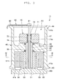
FIG. 3 is a view illustrating a cross-sectional structure of a yarn accumulating device; -
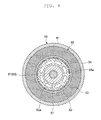
FIG. 4 is a view illustrating a cross-sectional structure taken along line IV-IV inFIG. 3 ; and -
FIG. 5 is a view illustrating a configuration of the spinning machine. - Hereinafter, an embodiment of the present invention will be described in detail with reference to the accompanying drawings. The same reference numerals are denoted on the same or corresponding elements in the description of the drawings, and the redundant description will be omitted. The dimensional ratio of the drawings may not necessarily match the description.
- As illustrated in
FIG. 1 , a spinning machine (yarn winding machine) 1 includes a plurality of spinning units (yarn winding units) 2, ayarn joining cart 3, a first end frame 4, asecond end frame 5, and a machine controller (setting section) 6. - The plurality of
spinning units 2 are arranged in a line, and eachspinning unit 2 produces a spun yarn Y and winds the spun yarn Y into a package P. Theyarn joining cart 3 performs a yarn joining operation in thespinning unit 2 in which the spun yarn Y is cut. The first end frame 4 accommodates an air supply source for generating a whirling airflow at each section of thespinning unit 2 and/or a suction source or the like for generating a suction flow at each section of thespinning unit 2. Thesecond end frame 5 accommodates a motor and the like for supplying power to each section of thespinning unit 2. Themachine controller 6 controls the operation of the entire spinning machine 1. - In the following description, on a path through which the spun yarn Y travels (i.e., yarn path), a side on which the spun yarn Y is produced is referred to as upstream and a side on which the spun yarn Y is wound is referred to as downstream. A side on which the yarn path is located with respect to the
yarn joining cart 3 is referred to as a front side, and a side opposite to the front side is referred to as a back side. A work passage (not illustrated) extending in a direction in which the plurality of spinningunits 2 are arranged is provided on the front side of the spinning machine 1. The operator thus can perform operation, monitoring, and the like of eachspinning unit 2 from the work passage. - As illustrated in
FIGS. 1 and2 , each spinningunit 2 includes adraft device 7, apneumatic spinning device 8, a yarn defect detecting section 9, atension sensor 10, ayarn accumulating device 11, awaxing device 12, and a windingdevice 13 in this order from the upstream. These devices are directly or indirectly supported by amachine frame 14 such that the upstream is an upper side in a machine height direction (i.e., downstream is a lower side in the machine height direction). - The
draft device 7 drafts a fiber bundle S. Thedraft device 7 includes aback roller pair 7a, athird roller pair 7b, amiddle roller pair 7d provided with anapron belt 7c on each roller, and afront roller pair 7e in this order from the upstream (the side from which the fiber bundle S is supplied in the feeding path of the fiber bundle S). - The
pneumatic spinning device 8 applies twists to the fiber bundle S drafted by thedraft device 7 using the whirling airflow to produce the spun yarn Y. The yarn defect detecting section 9 is adapted to monitor the travelling spun yarn Y between thepneumatic spinning device 8 and theyarn accumulating device 11. When the yarn defect is detected, the yarn defect detecting section 9 transmits a yarn defect detection signal to a unit controller (control section) 15. The yarn defect detecting section 9 detects, for example, a thickness abnormality of the spun yarn Y and/or foreign substance contained in the spun yarn Y as the yarn defect. - The
tension sensor 10 is adapted to measure tension of the travelling spun yarn Y between thepneumatic spinning device 8 and theyarn accumulating device 11, and transmit a tension measurement signal to theunit control section 15. Theyarn accumulating device 11 is adapted to accumulate the travelling spun yarn Y between thepneumatic spinning device 8 and the windingdevice 13. Theyarn accumulating device 11 has a function of stably pulling out the spun yarn Y from thepneumatic spinning device 8, a function of accumulating the spun yarn Y fed from thepneumatic spinning device 8 to prevent the spun yarn Y from slackening during the yarn joining operation by theyarn joining cart 3 or the like, and a function of adjusting the tension of the spun yarn Y at the windingdevice 13 to prevent a fluctuation in the tension of the spun yarn Y at the windingdevice 13 from being transmitted towards thepneumatic spinning device 8. - The waxing
device 12 is adapted to apply wax to the travelling spun yarn Y between theyarn accumulating device 11 and the windingdevice 13. Theunit control section 15 is provided for eachspinning unit 2, and is adapted to control an operation of thespinning unit 2. Theunit control section 15 is controlled by themachine controller 6. - The winding
device 13 is adapted to wind the spun yarn Y produced by thepneumatic spinning device 8 to form the package P. The windingdevice 13 includes acradle arm 21, a windingdrum 22, and atraverse device 23. Thecradle arm 21 is swingably supported by a supportingshaft 24, and causes a surface of the rotatably supported bobbin B or a surface of the package P to make contact with a surface of the windingdrum 22 at an appropriate pressure. The windingdrum 22 is driven by an electric motor (not illustrated) provided in eachspinning unit 2 to rotate the bobbin B or the package P making contact with the windingdrum 22. Thetraverse device 23 is driven by ashaft 25 shared among the plurality of spinningunits 2, and traverses the spun yarn Y over a prescribed width with respect to the rotating bobbin B or the package P. - The
yarn joining cart 3 travels to thespinning unit 2 in which the spun yarn Y is disconnected to perform the yarn joining operation in thetarget spinning unit 2. Theyarn joining cart 3 includes asplicer 26, asuction pipe 27, and asuction mouth 28. Thesuction pipe 27 is swingably supported by a supportingshaft 31, and is adapted to suck and catch a yarn end of the spun yarn Y from thepneumatic spinning device 8 to guide the yarn end to thesplicer 26. Thesuction mouth 28 is swingably supported by a supportingshaft 32, and is adapted to suck and catch a yarn end of the spun yarn Y from the windingdevice 13 to guide the yarn end to thesplicer 26. Thesplicer 26 joins the guided yarn ends. - A touch panel display (notifying section) D is connected to the
machine controller 6. The touch panel display D displays information related to various types of settings of the spinning machine 1 and information related to an operation state of the spinning machine 1, and receives an input from the operator. The touch panel display D functions as a display section and an input section. The touch panel display D displays a display screen based on display information output from themachine controller 6. The touch panel display D outputs operation information to themachine controller 6 when the display screen is operated by the operator. - The
yarn accumulating device 11 described above will be described more specifically. As illustrated inFIGS. 3 and4 , theyarn accumulating device 11 includes ayarn accumulating roller 40, a first motor (first driving section) 50, a yarn hooking member (yarn guiding member) 60, and a second motor (second driving section) 70. - The
yarn accumulating roller 40 includes ayarn accumulating section 41 and a supportingsection 42. The spun yarn Y is wound around an outer peripheral surface of theyarn accumulating section 41. Theyarn accumulating section 41 has a substantially cylindrical shape, and has abasal end portion 41a on a winding start side of the spun yarn Y and adistal end portion 41b on a side from which the spun yarn Y is unwound. Thebasal end portion 41a includes a basal end taperedportion 43. The basal end taperedportion 43 is formed such that the outer diameter becomes greater from thebasal end portion 41a towards the upstream. Thedistal end portion 41b includes a distal end taperedportion 44. The distal end taperedportion 44 is formed such that the outer diameter becomes greater from thedistal end portion 41b towards the downstream. In the present embodiment, for example, the outer peripheral surface of the portion between thebasal end portion 41a and thedistal end portion 41b has the same diameter, as illustrated inFIG. 3 , for example. However, the outer peripheral surface of the relevant portion may be provided with a surface having at least one tapered angle. A slit and the like may be formed on the surface of theyarn accumulating section 41. - As illustrated in
FIG. 3 , the supportingsection 42 is arranged on the inner side of theyarn accumulating section 41. The supportingsection 42 is located at a substantially central part in the rotation axis direction (hereinafter, simply referred to as rotation axis direction) of theyarn accumulating section 41, and projects further towards the inner side than aninner surface 41s of theyarn accumulating section 41. Thus, theyarn accumulating roller 40 has a substantially H-shaped cross-section along the rotation axis direction. The supportingsection 42 is provided with acircular hole 42h. The center of thehole 42h coincides with the rotation axis of theyarn accumulating roller 40. A first hollow region A1 close to thebasal end portion 41a and a second hollow region A2 close to thedistal end portion 41b are partitioned inside theyarn accumulating section 41 by the supportingsection 42. The supportingsection 42 is supported by afirst stator 51, to be described later. - The
first motor 50 rotates theyarn accumulating roller 40. Thefirst motor 50 is an outer rotor type stepping motor. Thefirst motor 50 is arranged on the inner side of theyarn accumulating section 41. Specifically, thefirst motor 50 is arranged in the first region A1. Thefirst motor 50 includes afirst stator 51, afirst stator 52, afirst rotor 53, and afirst rotor 54. - The
first stator 51 has a cylindrical shape, and is arranged so as to extend along the rotation axis direction and to be coaxial with the rotation axis. The basal end portion of thefirst stator 51 is fixed to a base section BS. The base section BS is fixed to themachine frame 14. The distal end portion of thefirst stator 51 is located in thehole 42h of the supportingsection 42. Two bearingmembers first stator 51 and the supportingsection 42. The bearingmembers members yarn accumulating section 41 is rotatably arranged with respect to thefirst stator 51 by the bearingmembers flyer shaft 61, to be described later, is inserted to ahollow portion 51h of thefirst stator 51. - The
first stator 52 has a cylindrical shape, and is arranged to surround the outer periphery of thefirst stator 51. Thefirst stator 52 is shorter than thefirst stator 51 in the rotation axis direction. The basal end portion of thefirst stator 52 is fixed to the base section BS. Thefirst stator 52 may be fixed to thefirst stator 51. In other words, thefirst stator 52 merely needs to be fixed to at least one of the base section BS and thefirst stator 51. As illustrated inFIG. 4 , bumps 52a are continuously formed along the peripheral direction on the outer peripheral surface of thefirst stator 52. A coil (not illustrated) is wound around thefirst stator 52. The coil is electrically connected to amotor driver 16 illustrated inFIG. 5 . - The
first rotor 53 is, for example, a permanent magnet, and has a cylindrical shape. Thefirst rotor 53 is arranged at a position surrounding thefirst stator 51 and thefirst stator 52, that is, in a region including thebasal end portion 41a. Thefirst rotor 53 is fixed to theinner surface 41s of theyarn accumulating section 41. - The
first rotor 54 has a cylindrical shape, and is fixed to the inner side of thefirst rotor 53.Bumps 54a are continuously formed along the peripheral direction on the inner peripheral surface of thefirst rotor 54. Thebumps 54a (the inner peripheral surface) of thefirst rotor 54 face thebumps 52a (the outer peripheral surface) of thefirst stator 52 at predetermined intervals. Thefirst rotor 54 is made from a material different from thefirst rotor 53. The material of thefirst rotor 54 is preferably a material that can be easily processed when forming thebumps 54a. - The
yarn hooking member 60 is arranged on a side (region including thedistal end portion 41b) close to the windingdevice 13 with respect to theyarn accumulating roller 40, and is rotatable with respect to theyarn accumulating roller 40. Theyarn hooking member 60 hooks the spun yarn Y, and winds the yarn Y around theyarn accumulating roller 40. Theyarn hooking member 60 includes aflyer shaft 61 and aflyer 62. - The
flyer shaft 61 extends along the rotation axis direction. The rotation axis of theflyer shaft 61 is coaxial with the rotation axis of theyarn accumulating section 41.FIG. 3 illustrates a structure in which theflyer shaft 61 extends to the basal end portion of thefirst stator 51, but theflyer shaft 61 may not extend to the basal end portion of thefirst stator 51. Theflyer 62 is fixed to a distal end of theflyer shaft 61, and is curved to hook the spun yarn Y. - The
second motor 70 rotates theyarn hooking member 60. Thesecond motor 70 is, for example, a brushless motor. Thesecond motor 70 is arranged on the inner side of theyarn accumulating section 41. Specifically, thesecond motor 70 is arranged in the second region A2 on the inner side of theyarn accumulating section 41. Thesecond motor 70 includes asecond stator 71 and asecond rotor 72. Thesecond motor 70 is driven independently from thefirst motor 50. - The
second stator 71 is fixed to the distal end of thefirst stator 51 of thefirst motor 50. Thesecond stator 71 has a cylindrical shape. Thesecond stator 71 is provided with ahole 71h through which theflyer shaft 61 is inserted. The center of thehole 71h coincides with the rotation axis of theyarn accumulating roller 40. A coil (not illustrated) is wound around thesecond stator 71. The coil is electrically connected to themotor driver 16 through thehollow portion 51h of thefirst stator 51. -
Bearing members second stator 71 and theflyer shaft 61. A bearing, a bush, or the like, for example, can be used as the bearingmembers members - The
second rotor 72 is fixed to theflyer shaft 61. Thesecond rotor 72 is located in thehole 71h of thesecond stator 71, and is arranged between the two bearingmembers second rotor 72 faces the inner peripheral surface of thesecond stator 71 with a predetermined interval therebetween. The flyer shaft 61 (the yarn hooking member 60) rotates by the rotation of thesecond rotor 72. - The drive of the
first motor 50 having the configuration described above is controlled by themotor driver 16 receiving a pulse signal output from theunit control section 15. Themotor driver 16 may be arranged for eachspinning unit 2, may be incorporated in theunit control section 15, or may be incorporated in themachine controller 6. In the present embodiment, themotor driver 16 is arranged for eachspinning unit 2. The motor driver controls the drive of thefirst motor 50 based on the pulse signal output from theunit control section 15. The amount of current to be flown through the coil, the direction of the current, the timing, and the like are set for the pulse signal. - The setting of the pulse signal output from the
unit control section 15, that is, the drive setting of thefirst motor 50 can be made by the operation of the touch panel display D. When the information associated with the drive of thefirst motor 50 is input in the touch panel display D, the setting is made in themachine controller 6 thus generating the setting information, and the setting information is output to theunit control section 15. Theunit control section 15 outputs the pulse signal to themotor driver 16 based on the setting information. When current is supplied from themotor driver 16 to the coil based on the pulse signal output from theunit control section 15, thefirst motor 50 rotates thefirst rotor 53 and thefirst rotor 54. The yarn accumulating section 41 (the yarn accumulating roller 40) fixed to thefirst rotor 53 thereby rotates. - The
first motor 50, for example, may step out when a load greater than or equal to the threshold value set in advance is applied, or when a sudden speed change occurs. Theunit control section 15 can detect the step-out of thefirst motor 50. In other words, theunit control section 15 has a function of a step-out detecting section adapted to detect the step-out of thefirst motor 50. Theunit control section 15, for example, monitors the synchronization of the pulse signal and the rotation of thefirst motor 50, and detects the step-out of thefirst motor 50 when detecting that the pulse signal and the rotation of thefirst motor 50 are not synchronized. When detecting the step-out of thefirst motor 50, theunit control section 15 stops the operation of theyarn accumulating device 11 and also stops the operation of thepneumatic spinning device 8, and outputs a step-out detection signal to themachine controller 6. Upon receiving the step-out detection signal, themachine controller 6 displays, for example, a text indicating occurrence of the step-out on the touch panel display D. The notification of the occurrence of the step-out may be made through other means (buzzer, lamp, or the like) - The drive of the
second motor 70 is controlled by themotor driver 16 receiving a pulse signal output from theunit control section 15. The motor driver controls the drive of thesecond motor 70 based on the drive signal output from theunit control section 15. The amount of current flown through the coil, the direction of the current, the timing, and the like are set for the drive signal. The setting of the drive signal output from theunit control section 15, that is, the drive setting of thesecond motor 70 can be made by the operation of the touch panel display D. When the information associated with the drive of thesecond motor 70 is input in the touch panel display D, the setting is made in themachine controller 6 thus generating the setting information, and the setting information is output to theunit control section 15. Theunit control section 15 outputs the drive signal to themotor driver 16 based on the setting information. Only onemotor driver 16 is described inFIG. 5 , but themotor driver 16 is actually arranged in each of thefirst motor 50 and thesecond motor 70. According to such a configuration, thefirst motor 50 and thesecond motor 70 can be rotated at different rotation numbers. - When current is supplied from the
motor driver 16 to the coil based on the drive signal output from theunit control section 15, thesecond motor 70 rotates thesecond rotor 72. The flyer shaft 61 (the yarn hooking member 60) fixed to thesecond rotor 72 thereby rotates. Thesecond motor 70 rotates in the same direction as the rotating direction of thefirst motor 50 and relatively rotates with respect to the rotation of thefirst motor 50. Thesecond motor 70 is rotatable at the rotation speed higher than thefirst motor 50. In other words, theyarn hooking member 60 can be rotated faster than theyarn accumulating roller 40. - Next, a description will be made on the operation of the
yarn accumulating device 11. In thespinning unit 2, when the normal operation of producing the spun yarn Y and winding the spun yarn Y into the package P is carried out, theunit control section 15 controls thefirst motor 50 and thesecond motor 70 such that theyarn accumulating roller 40 rotates at a substantially constant rotation speed and theyarn hooking member 60 rotates in the same direction and at the same rotation speed as theyarn accumulating roller 40. Theyarn hooking member 60 that rotates while hooking the spun yarn Y thereby winds the spun yarn Y around the rotatingyarn accumulating roller 40. - When the tension of the spun yarn Y on the downstream of the
yarn accumulating device 11 becomes high under a state where the spun yarn Y is wound around theyarn accumulating roller 40, theunit control section 15 controls thesecond motor 70 such that theyarn hooking member 60 relatively rotates with respect to theyarn accumulating roller 40. The spun yarn Y is thereby unwound from theyarn accumulating roller 40. When the tension of the spun yarn Y on the downstream of theyarn accumulating device 11 becomes low, theunit control section 15 controls thesecond motor 70 such that theyarn hooking member 60 rotates in the same direction as theyarn accumulating roller 40 and at the same rotation speed as theyarn accumulating roller 40. The spun yarn Y is thereby wound around theyarn accumulating roller 40. - When starting the accumulation of the spun yarn Y in the
yarn accumulating device 11, theunit control section 15 controls thefirst motor 50 and thesecond motor 70 so as to start the rotation of theyarn accumulating roller 40 and to start the rotation of theyarn hooking member 60. In this case, theunit control section 15 controls thefirst motor 50 and thesecond motor 70 such that the rotation speed of theyarn hooking member 60 becomes higher than the rotation speed of theyarn accumulating roller 40. The spun yarn Y is thereby wound around the outer peripheral surface of theyarn accumulating roller 40 while applying tension on the spun yarn Y. - The
unit control section 15 may control the drive of thesecond motor 70 according to the winding amount of the spun yarn Y wound into the package P. For example, theunit control section 15 may control thesecond motor 70 such that theyarn hooking member 60 rotates at a first speed at the start of formation of the package P by winding the spun yarn Y around the bobbin B, that is, at the start of winding of the spun yarn Y, and control thesecond motor 70 such that theyarn hooking member 60 rotates at a second speed lower than the first speed at the end of formation of the package P, that is, at the end of winding of the spun yarn Y. In other words, theunit control section 15 may control the drive of thesecond motor 70 such that the tension at the start of the winding of the package P becomes high and the tension at the end of the winding becomes low. - As described above, in the
yarn accumulating device 11 of the present embodiment, thefirst motor 50 is configured such that thefirst rotor 53 rotates around thefirst stator 51 located on the inner side of theyarn accumulating section 41. In other words, thefirst motor 50 is a so-called outer rotor type motor. Thus, thefirst stator 51, which does not rotate even if theyarn accumulating roller 40 rotates, exists on the inner side of theyarn accumulating section 41. Thesecond stator 71 is fixed at the distal end of thefirst stator 51 arranged so as to extend in the rotation axis direction of theyarn accumulating roller 40 and to be coaxial with the rotation axis, such that theyarn hooking member 60 can be driven coaxially with the rotation axis of theyarn accumulating roller 40. Therefore, theyarn accumulating roller 40 and theyarn hooking member 60 can be driven independently from each other. More specifically, thefirst stator 51 has a cylindrical shape, and the cylindrical central shaft is arranged so as to overlap the rotation axis of theyarn accumulating roller 40. - In the present embodiment, the
yarn accumulating device 11 has two bearingmembers yarn accumulating roller 40 to freely rotate with respect to thefirst stator 51, arranged between thefirst stator 51 and the supportingsection 42. Thus, theyarn accumulating roller 40 can be stably rotated. If one bearing member is arranged between the supportingsection 42 of theyarn accumulating section 41 and thefirst stator 51, and one bearing member is arranged on thebasal end portion 41a side of theyarn accumulating section 41, a structure adapted to support the bearing member arranged on thebasal end portion 41a side is required. As a result, the structure on thebasal end portion 41a side becomes complex and the space is closed, and hence the heat may be enclosed in theyarn accumulating roller 40. In the present embodiment, since thebasal end portion 41a side of theyarn accumulating section 41 is opened, the heat radiating performance is improved. - In the present embodiment, the
first motor 50 is a stepping motor. Thefirst motor 50 can be controlled at a constant torque, so that theyarn accumulating roller 40 can be stably rotated. As a result, the spun yarn Y can be stably accumulated in the spinning machine 1 including theyarn accumulating device 11. - In the present embodiment, the
first motor 50 is assumed as the stepping motor, and thus thefirst motor 50 may step out. When detecting the step-out of thefirst motor 50, theunit control section 15 stops the operation of theyarn accumulating device 11 and also stops the operation of thepneumatic spinning device 8. Thus, for example, the spun yarn Y in faulty states can be prevented from being accumulated in theyarn accumulating device 11, and the lowering of the quality of the spun yarn Y can be suppressed. When the step-out of thefirst motor 50 is detected, this is displayed on the touch panel display D, and thespinning unit 2 including theyarn accumulating device 11 in which the step-out has occurred can be notified to the operator. - In the present embodiment, the setting of the tension to be applied to the spun yarn Y by the
yarn hooking member 60 in theyarn accumulating device 11 arranged in eachspinning unit 2, that is, the drive setting of thesecond motor 70 can be carried out all at once by the operation of the touch panel display D. Therefore, the setting operation of the tension can be easily carried out in theyarn accumulating device 11 of the present embodiment. - When starting the winding of the spun yarn Y in the
yarn accumulating roller 40, time may be required until the rotation speed of thefirst motor 50 reaches a predetermined speed. In this case, the tension of the spun yarn Y is low (zero tension), and the spun yarn Y may be loosely wound around theyarn accumulating roller 40. In the present embodiment, thefirst motor 50 and thesecond motor 70 can be independently driven, and thus the rotation speed of theyarn hooking member 60 can be set higher than the rotation speed of theyarn accumulating roller 40 at the start of the winding of the spun yarn Y around theyarn accumulating roller 40. Thus, the spun yarn Y can be wound around theyarn accumulating roller 40 at high speed by theyarn hooking member 60, and the tension can be applied to the spun yarn Y. Theyarn accumulating device 11 thus can reduce the return time from zero tension, and suppress the spun yarn Y from being loosely wound around theyarn accumulating roller 40. - In the present embodiment, the tension of the spun yarn Y wound into the package P in the winding
device 13 can be changed (adjusted) by the rotation speed of theyarn hooking member 60. When forming the package P in the windingdevice 13, the winding tension is set high when the winding diameter is small and the winding tension is set lower as the winding diameter becomes larger to obtain a satisfactory package shape. Therefore, the rotation of theyarn hooking member 60 is changed to set the tension high at the start of the winding of the package P and to set the tension low at the end of the winding to form a satisfactory package P. - In the present embodiment, the
first motor 50 and thesecond motor 70 are located on the inner side of theyarn accumulating section 41. Thus, theyarn accumulating roller 40 can be made small. As a result, theyarn accumulating roller 40 can be arranged in a narrow space and the like, for example. - The present invention is not limited to the embodiment described above. For example, in the embodiment described above, a mode in which the
first motor 50 includes thefirst stator 51 and thefirst stator 52 as the first stator has been described by way of example. However, at least one first stator merely needs to be arranged. Similarly, a mode in which thefirst motor 50 includes thefirst rotor 53 and thefirst rotor 54 as the first rotor has been described by way of example. However, at least one first rotor merely needs to be arranged. - In the embodiment described above, a mode in which the
first stator 51 has a hollow cylindrical shape has been described by way of example, but thefirst stator 51 may have a circular column shape. In this case, theflyer shaft 61 merely needs to have a length that can be accommodated in thesecond stator 71. - In the embodiment described above, a mode in which the supporting
section 42 is arranged substantially at the central part in the rotation axis direction in theyarn accumulating section 41 has been described by way of example, but the position of the supportingsection 42 is not limited thereto. The supportingsection 42 may be arranged closer to thebasal end portion 41a of theyarn accumulating section 41 or may be arranged closer to thedistal end portion 41b. - In the embodiment described above, the configuration in which the
unit control section 15 controls the drive of thefirst motor 50 and thesecond motor 70 and detects the step-out of thefirst motor 50 has been described by way of example. The control section adapted to control the drive of thefirst motor 50 and thesecond motor 70 and the detecting section adapted to detect the step-out of thefirst motor 50 may be arranged independently from theunit control section 15 as one configuration of theyarn accumulating device 11. - In the embodiment described above, a mode in which the
second motor 70 is the brushless motor has been described by way of example, but thesecond motor 70 may be another motor type. - In the embodiment described above, a mode in which the
unit control section 15 functions as a step-out detecting section has been described by way of example, but the step-out detecting section may be arranged independently from theunit control section 15. The step-out of thefirst motor 50 may be detected by the yarn defect detecting section 9. When thefirst motor 50 steps out, the thickness and the like of the spun yarn Y pulled out from theyarn accumulating roller 40 change. Thus, the step-out of thefirst motor 50 can be indirectly detected by the yarn defect detecting section 9. - In the embodiment described above, a mode of starting the winding of the spun yarn Y around the
yarn accumulating roller 40 with the start of the rotation of thefirst motor 50 has been described by way of example. However, when the rotation speed of theyarn accumulating roller 40 reaches a predetermined speed, the spinning of the spun yarn Y may be started in thepneumatic spinning device 8 to wind the spun yarn Y around theyarn accumulating roller 40. - In addition to the embodiment described above, an encoder adapted to monitor the rotation state of the
second motor 70 may be arranged. A highly accurate rotation control of theyarn hooking member 60 can be carried out by arranging the encoder. - In the embodiment described above, the spinning machine 1 is described as the yarn winding machine by way of example, but the yarn winding machine may be an automatic winder or the like.
Claims (11)
- A yarn accumulating device (11) comprising:a yarn accumulating roller (40) around which a yarn is wound;a yarn guiding member (60) rotatable with respect to the yarn accumulating roller (40);a first driving section (50) adapted to rotatably drive the yarn accumulating roller (40); anda second driving section (70) adapted to rotatably drive the yarn guiding member (60),wherein the yarn accumulating roller (40) includes
a yarn accumulating section (41) around which the yarn is wound, and
a supporting section (42) arranged on an inner side of the yarn accumulating section (41),the first driving section (50) includes
a first stator (51) located on the inner side of the yarn accumulating section (41) and arranged so as to extend along a rotation axis direction of the yarn accumulating roller (40) and to be coaxial with a rotation axis, and
a first rotor (53) fixed on the inner side of the yarn accumulating section (41) at a position surrounding the first stator (51),characterized in thatthe second driving section (70) includes
a second stator (71) located on the inner side of the yarn accumulating section (41) and fixed to a distal end of the first stator (51), and
a second rotor (72) fixed to the yarn guiding member (60),the supporting section (42) surrounds the distal end of the first stator (51) and is arranged between the first rotor (53) and the second stator (71), and is supported by the first stator (51), andat least two bearing members (55, 56) that enable the yarn accumulating roller (40) to freely rotate with respect to the first stator (51) are arranged between the first stator (51) and the supporting section (42). - The yarn accumulating device (11) according to claim 1, characterized in that the first driving section (50) is a stepping motor.
- The yarn accumulating device (11) according to claim 2, further characterized by
a control section (15) adapted to control drive of the first driving section (50),
wherein the control section (15) stops the drive of the first driving section (50) when the first driving section (50) steps out. - The yarn accumulating device (11) according to claim 3, characterized in that the control section (15) stops the drive of the first driving section (50) when the step-out of the first driving section (50) is detected.
- The yarn accumulating device (11) according to any one of claims 1 to 4, characterized in that the second driving section (70) rotates the yarn guiding member (60) at a speed greater than or equal to a rotation speed of the yarn accumulating roller (40).
- The yarn accumulating device (11) according to claim 3 or 4, characterized in that the control section (15) controls drive of the second driving section (70).
- A yarn winding unit (2) comprising:the yarn accumulating device (11) according to any one of claims 1 to 6;a spinning device (8) adapted to produce the yarn to be wound around the yarn accumulating roller (40) of the yarn accumulating device (11); anda winding device (13) adapted to wind the yarn pulled out from the yarn accumulating roller (40) into a package.
- A yarn winding unit (2) comprising:the yarn accumulating device (11) according to any one of claims 3, 4, or 6;a spinning device (8) adapted to produce the yarn to be wound around the yarn accumulating roller (40) of the yarn accumulating device (11);a winding device (13) adapted to wind the yarn pulled out from the yarn accumulating roller (40) into a package; anda unit control section (15) adapted to stop an operation of the spinning device (8) when the first driving section (50) steps out,wherein the control section (15) is the unit control section (15).
- The yarn winding unit (2) according to claim 7 or 8, further comprising:a notifying section (D) adapted to notify the step-out of the first driving section (50) when the first driving section (50) steps out.
- The yarn winding unit (2) according to claim 8, wherein the unit control section (15) controls the drive of the second driving section (70) during the winding of the yarn in the winding device (13) to change a rotation speed of the yarn guiding member (60).
- A yarn winding machine (1) comprising:a plurality of yarn winding units (2) according to any one of claims 6 to 10; anda setting section (6) adapted to carry out setting of tension of the yarn wound in the winding device (13) of each of the yarn winding units (2).
Applications Claiming Priority (1)
| Application Number | Priority Date | Filing Date | Title |
|---|---|---|---|
| JP2014142472A JP2016016969A (en) | 2014-07-10 | 2014-07-10 | Yarn storage device, yarn take-up unit, and yarn take-up machine |
Publications (2)
| Publication Number | Publication Date |
|---|---|
| EP2966020A1 true EP2966020A1 (en) | 2016-01-13 |
| EP2966020B1 EP2966020B1 (en) | 2016-11-23 |
Family
ID=53268712
Family Applications (1)
| Application Number | Title | Priority Date | Filing Date |
|---|---|---|---|
| EP15169263.9A Not-in-force EP2966020B1 (en) | 2014-07-10 | 2015-05-26 | Yarn accumulating device, yarn winding unit, and yarn winding machine |
Country Status (3)
| Country | Link |
|---|---|
| EP (1) | EP2966020B1 (en) |
| JP (1) | JP2016016969A (en) |
| CN (1) | CN105274662B (en) |
Cited By (4)
| Publication number | Priority date | Publication date | Assignee | Title |
|---|---|---|---|---|
| CN110172768A (en) * | 2019-06-19 | 2019-08-27 | 苏州济洋纺织机械有限公司 | A kind of yarn heat setting device |
| CN110657653A (en) * | 2019-09-19 | 2020-01-07 | 苏州济洋纺织机械有限公司 | Spooling unit capable of drying yarns |
| DE102018119164A1 (en) * | 2018-08-07 | 2020-02-13 | Maschinenfabrik Rieter Ag | Yarn store for a spinning or winding machine |
| EP3715294A1 (en) | 2019-03-29 | 2020-09-30 | Maschinenfabrik Rieter Ag | Method for controlling a workstation of a textile machine, a device for performing the method |
Citations (3)
| Publication number | Priority date | Publication date | Assignee | Title |
|---|---|---|---|---|
| EP2075359A2 (en) * | 2007-12-27 | 2009-07-01 | Murata Machinery, Ltd. | Yarn slack eliminating device and spinning machine |
| JP2010077576A (en) | 2008-09-29 | 2010-04-08 | Murata Machinery Ltd | Spinning machine |
| EP2684827A2 (en) * | 2012-07-12 | 2014-01-15 | Rieter CZ s.r.o. | A drum inter-storage of yarn at an operating unit of a textile machine and method of controlling it |
Family Cites Families (12)
| Publication number | Priority date | Publication date | Assignee | Title |
|---|---|---|---|---|
| JP5007826B2 (en) * | 2008-03-31 | 2012-08-22 | 村田機械株式会社 | Yarn winding device and automatic winder equipped with this yarn winding device |
| WO2011040545A1 (en) * | 2009-09-30 | 2011-04-07 | 村田機械株式会社 | Yarn winder |
| CN102548884B (en) * | 2009-09-30 | 2016-03-16 | 村田机械株式会社 | Yarn take-up device |
| WO2011040546A1 (en) * | 2009-09-30 | 2011-04-07 | 村田機械株式会社 | Yarn winder |
| JP5365697B2 (en) * | 2009-09-30 | 2013-12-11 | 村田機械株式会社 | Yarn winding device |
| JP5471924B2 (en) * | 2010-07-15 | 2014-04-16 | 村田機械株式会社 | Yarn winding device |
| JP5471923B2 (en) * | 2010-07-15 | 2014-04-16 | 村田機械株式会社 | Yarn winding device |
| JP2012096867A (en) * | 2010-10-29 | 2012-05-24 | Murata Machinery Ltd | String retention and extraction system and string winding machine |
| JP5804306B2 (en) * | 2011-02-07 | 2015-11-04 | 村田機械株式会社 | Yarn storage device and yarn winding machine |
| JP2013063839A (en) * | 2011-09-20 | 2013-04-11 | Murata Machinery Ltd | Yarn winding machine and yarn winding unit |
| JP2013067874A (en) * | 2011-09-20 | 2013-04-18 | Murata Mach Ltd | Spinning unit and spinning device |
| JP5915219B2 (en) * | 2012-02-07 | 2016-05-11 | 村田機械株式会社 | Yarn winding device |
-
2014
- 2014-07-10 JP JP2014142472A patent/JP2016016969A/en active Pending
-
2015
- 2015-05-11 CN CN201510235999.2A patent/CN105274662B/en active Active
- 2015-05-26 EP EP15169263.9A patent/EP2966020B1/en not_active Not-in-force
Patent Citations (3)
| Publication number | Priority date | Publication date | Assignee | Title |
|---|---|---|---|---|
| EP2075359A2 (en) * | 2007-12-27 | 2009-07-01 | Murata Machinery, Ltd. | Yarn slack eliminating device and spinning machine |
| JP2010077576A (en) | 2008-09-29 | 2010-04-08 | Murata Machinery Ltd | Spinning machine |
| EP2684827A2 (en) * | 2012-07-12 | 2014-01-15 | Rieter CZ s.r.o. | A drum inter-storage of yarn at an operating unit of a textile machine and method of controlling it |
Cited By (7)
| Publication number | Priority date | Publication date | Assignee | Title |
|---|---|---|---|---|
| DE102018119164A1 (en) * | 2018-08-07 | 2020-02-13 | Maschinenfabrik Rieter Ag | Yarn store for a spinning or winding machine |
| EP3611295A1 (en) * | 2018-08-07 | 2020-02-19 | Maschinenfabrik Rieter AG | Yarn accumulating device for a spinning or winding machine |
| CN110817573A (en) * | 2018-08-07 | 2020-02-21 | 里特机械公司 | Yarn storage for spinning machines or winders |
| CN110817573B (en) * | 2018-08-07 | 2023-02-17 | 里特机械公司 | Yarn storage device for spinning machine or winding machine |
| EP3715294A1 (en) | 2019-03-29 | 2020-09-30 | Maschinenfabrik Rieter Ag | Method for controlling a workstation of a textile machine, a device for performing the method |
| CN110172768A (en) * | 2019-06-19 | 2019-08-27 | 苏州济洋纺织机械有限公司 | A kind of yarn heat setting device |
| CN110657653A (en) * | 2019-09-19 | 2020-01-07 | 苏州济洋纺织机械有限公司 | Spooling unit capable of drying yarns |
Also Published As
| Publication number | Publication date |
|---|---|
| CN105274662A (en) | 2016-01-27 |
| CN105274662B (en) | 2018-12-14 |
| EP2966020B1 (en) | 2016-11-23 |
| JP2016016969A (en) | 2016-02-01 |
Similar Documents
| Publication | Publication Date | Title |
|---|---|---|
| EP2309042B1 (en) | Spinning unit | |
| EP2966020B1 (en) | Yarn accumulating device, yarn winding unit, and yarn winding machine | |
| EP2966203B1 (en) | Spinning machine and spinning method | |
| EP2075359A2 (en) | Yarn slack eliminating device and spinning machine | |
| EP3269851B1 (en) | Spinning machine | |
| EP2966200B1 (en) | Spinning machine and spinning method | |
| EP2966021A1 (en) | Yarn winding machine and yarn winding method | |
| TWI778228B (en) | Draw texturing machine | |
| EP2671830A2 (en) | Textile machine, standby position determining method of driven member of winding unit, and winding unit | |
| EP2962973A1 (en) | Yarn winding device | |
| EP2573224B1 (en) | Spinning unit and spinning device | |
| EP2808283A1 (en) | Yarn winding machine | |
| EP1717182B1 (en) | Yarn slack eliminating device in textile machine | |
| EP2690043B1 (en) | Driving state detecting device, winding unit, winding machine, spinning unit, and spinning machine | |
| EP2977493B1 (en) | Spinning machine and spinning method | |
| JP2010042904A (en) | Yarn winding machine | |
| JP2012250810A (en) | Thread winder | |
| CN105905680B (en) | Yarn reeling device and fiber are mechanical | |
| JP2008105755A (en) | Loosened yarn-tightening device incorporating electromagnetic tenser | |
| EP2738128B1 (en) | Yarn winding machine | |
| EP3599299B1 (en) | Drafting device, spinning unit, and spinning machine | |
| EP2690044A2 (en) | Yarn winding device | |
| JP2003249133A (en) | Wire rod feeder | |
| CN111683888B (en) | Yarn winding machine and yarn winding method | |
| EP3689803B1 (en) | Thread winding device |
Legal Events
| Date | Code | Title | Description |
|---|---|---|---|
| PUAI | Public reference made under article 153(3) epc to a published international application that has entered the european phase |
Free format text: ORIGINAL CODE: 0009012 |
|
| AK | Designated contracting states |
Kind code of ref document: A1 Designated state(s): AL AT BE BG CH CY CZ DE DK EE ES FI FR GB GR HR HU IE IS IT LI LT LU LV MC MK MT NL NO PL PT RO RS SE SI SK SM TR |
|
| AX | Request for extension of the european patent |
Extension state: BA ME |
|
| 17P | Request for examination filed |
Effective date: 20160122 |
|
| RBV | Designated contracting states (corrected) |
Designated state(s): AL AT BE BG CH CY CZ DE DK EE ES FI FR GB GR HR HU IE IS IT LI LT LU LV MC MK MT NL NO PL PT RO RS SE SI SK SM TR |
|
| GRAP | Despatch of communication of intention to grant a patent |
Free format text: ORIGINAL CODE: EPIDOSNIGR1 |
|
| INTG | Intention to grant announced |
Effective date: 20160608 |
|
| GRAS | Grant fee paid |
Free format text: ORIGINAL CODE: EPIDOSNIGR3 |
|
| GRAA | (expected) grant |
Free format text: ORIGINAL CODE: 0009210 |
|
| AK | Designated contracting states |
Kind code of ref document: B1 Designated state(s): AL AT BE BG CH CY CZ DE DK EE ES FI FR GB GR HR HU IE IS IT LI LT LU LV MC MK MT NL NO PL PT RO RS SE SI SK SM TR |
|
| REG | Reference to a national code |
Ref country code: GB Ref legal event code: FG4D |
|
| REG | Reference to a national code |
Ref country code: CH Ref legal event code: EP |
|
| REG | Reference to a national code |
Ref country code: IE Ref legal event code: FG4D |
|
| REG | Reference to a national code |
Ref country code: AT Ref legal event code: REF Ref document number: 847688 Country of ref document: AT Kind code of ref document: T Effective date: 20161215 |
|
| REG | Reference to a national code |
Ref country code: DE Ref legal event code: R096 Ref document number: 602015000785 Country of ref document: DE |
|
| REG | Reference to a national code |
Ref country code: DE Ref legal event code: R096 Ref document number: 602015000785 Country of ref document: DE |
|
| REG | Reference to a national code |
Ref country code: CH Ref legal event code: NV Representative=s name: ING. ALESSANDRO GALASSI C/O PGA S.P.A., MILANO, CH |
|
| PG25 | Lapsed in a contracting state [announced via postgrant information from national office to epo] |
Ref country code: LV Free format text: LAPSE BECAUSE OF FAILURE TO SUBMIT A TRANSLATION OF THE DESCRIPTION OR TO PAY THE FEE WITHIN THE PRESCRIBED TIME-LIMIT Effective date: 20161123 |
|
| REG | Reference to a national code |
Ref country code: LT Ref legal event code: MG4D |
|
| REG | Reference to a national code |
Ref country code: NL Ref legal event code: MP Effective date: 20161123 |
|
| REG | Reference to a national code |
Ref country code: AT Ref legal event code: MK05 Ref document number: 847688 Country of ref document: AT Kind code of ref document: T Effective date: 20161123 |
|
| PG25 | Lapsed in a contracting state [announced via postgrant information from national office to epo] |
Ref country code: NO Free format text: LAPSE BECAUSE OF FAILURE TO SUBMIT A TRANSLATION OF THE DESCRIPTION OR TO PAY THE FEE WITHIN THE PRESCRIBED TIME-LIMIT Effective date: 20170223 Ref country code: NL Free format text: LAPSE BECAUSE OF FAILURE TO SUBMIT A TRANSLATION OF THE DESCRIPTION OR TO PAY THE FEE WITHIN THE PRESCRIBED TIME-LIMIT Effective date: 20161123 Ref country code: LT Free format text: LAPSE BECAUSE OF FAILURE TO SUBMIT A TRANSLATION OF THE DESCRIPTION OR TO PAY THE FEE WITHIN THE PRESCRIBED TIME-LIMIT Effective date: 20161123 Ref country code: SE Free format text: LAPSE BECAUSE OF FAILURE TO SUBMIT A TRANSLATION OF THE DESCRIPTION OR TO PAY THE FEE WITHIN THE PRESCRIBED TIME-LIMIT Effective date: 20161123 Ref country code: GR Free format text: LAPSE BECAUSE OF FAILURE TO SUBMIT A TRANSLATION OF THE DESCRIPTION OR TO PAY THE FEE WITHIN THE PRESCRIBED TIME-LIMIT Effective date: 20170224 |
|
| PG25 | Lapsed in a contracting state [announced via postgrant information from national office to epo] |
Ref country code: FI Free format text: LAPSE BECAUSE OF FAILURE TO SUBMIT A TRANSLATION OF THE DESCRIPTION OR TO PAY THE FEE WITHIN THE PRESCRIBED TIME-LIMIT Effective date: 20161123 Ref country code: HR Free format text: LAPSE BECAUSE OF FAILURE TO SUBMIT A TRANSLATION OF THE DESCRIPTION OR TO PAY THE FEE WITHIN THE PRESCRIBED TIME-LIMIT Effective date: 20161123 Ref country code: PL Free format text: LAPSE BECAUSE OF FAILURE TO SUBMIT A TRANSLATION OF THE DESCRIPTION OR TO PAY THE FEE WITHIN THE PRESCRIBED TIME-LIMIT Effective date: 20161123 Ref country code: AT Free format text: LAPSE BECAUSE OF FAILURE TO SUBMIT A TRANSLATION OF THE DESCRIPTION OR TO PAY THE FEE WITHIN THE PRESCRIBED TIME-LIMIT Effective date: 20161123 Ref country code: ES Free format text: LAPSE BECAUSE OF FAILURE TO SUBMIT A TRANSLATION OF THE DESCRIPTION OR TO PAY THE FEE WITHIN THE PRESCRIBED TIME-LIMIT Effective date: 20161123 Ref country code: PT Free format text: LAPSE BECAUSE OF FAILURE TO SUBMIT A TRANSLATION OF THE DESCRIPTION OR TO PAY THE FEE WITHIN THE PRESCRIBED TIME-LIMIT Effective date: 20170323 Ref country code: RS Free format text: LAPSE BECAUSE OF FAILURE TO SUBMIT A TRANSLATION OF THE DESCRIPTION OR TO PAY THE FEE WITHIN THE PRESCRIBED TIME-LIMIT Effective date: 20161123 |
|
| PG25 | Lapsed in a contracting state [announced via postgrant information from national office to epo] |
Ref country code: RO Free format text: LAPSE BECAUSE OF FAILURE TO SUBMIT A TRANSLATION OF THE DESCRIPTION OR TO PAY THE FEE WITHIN THE PRESCRIBED TIME-LIMIT Effective date: 20161123 Ref country code: EE Free format text: LAPSE BECAUSE OF FAILURE TO SUBMIT A TRANSLATION OF THE DESCRIPTION OR TO PAY THE FEE WITHIN THE PRESCRIBED TIME-LIMIT Effective date: 20161123 Ref country code: DK Free format text: LAPSE BECAUSE OF FAILURE TO SUBMIT A TRANSLATION OF THE DESCRIPTION OR TO PAY THE FEE WITHIN THE PRESCRIBED TIME-LIMIT Effective date: 20161123 Ref country code: SK Free format text: LAPSE BECAUSE OF FAILURE TO SUBMIT A TRANSLATION OF THE DESCRIPTION OR TO PAY THE FEE WITHIN THE PRESCRIBED TIME-LIMIT Effective date: 20161123 |
|
| REG | Reference to a national code |
Ref country code: DE Ref legal event code: R097 Ref document number: 602015000785 Country of ref document: DE |
|
| PG25 | Lapsed in a contracting state [announced via postgrant information from national office to epo] |
Ref country code: SM Free format text: LAPSE BECAUSE OF FAILURE TO SUBMIT A TRANSLATION OF THE DESCRIPTION OR TO PAY THE FEE WITHIN THE PRESCRIBED TIME-LIMIT Effective date: 20161123 Ref country code: BG Free format text: LAPSE BECAUSE OF FAILURE TO SUBMIT A TRANSLATION OF THE DESCRIPTION OR TO PAY THE FEE WITHIN THE PRESCRIBED TIME-LIMIT Effective date: 20170223 Ref country code: LU Free format text: LAPSE BECAUSE OF NON-PAYMENT OF DUE FEES Effective date: 20170531 Ref country code: IT Free format text: LAPSE BECAUSE OF FAILURE TO SUBMIT A TRANSLATION OF THE DESCRIPTION OR TO PAY THE FEE WITHIN THE PRESCRIBED TIME-LIMIT Effective date: 20161123 Ref country code: BE Free format text: LAPSE BECAUSE OF FAILURE TO SUBMIT A TRANSLATION OF THE DESCRIPTION OR TO PAY THE FEE WITHIN THE PRESCRIBED TIME-LIMIT Effective date: 20161123 |
|
| PLBE | No opposition filed within time limit |
Free format text: ORIGINAL CODE: 0009261 |
|
| STAA | Information on the status of an ep patent application or granted ep patent |
Free format text: STATUS: NO OPPOSITION FILED WITHIN TIME LIMIT |
|
| 26N | No opposition filed |
Effective date: 20170824 |
|
| PG25 | Lapsed in a contracting state [announced via postgrant information from national office to epo] |
Ref country code: SI Free format text: LAPSE BECAUSE OF FAILURE TO SUBMIT A TRANSLATION OF THE DESCRIPTION OR TO PAY THE FEE WITHIN THE PRESCRIBED TIME-LIMIT Effective date: 20161123 |
|
| PG25 | Lapsed in a contracting state [announced via postgrant information from national office to epo] |
Ref country code: MC Free format text: LAPSE BECAUSE OF FAILURE TO SUBMIT A TRANSLATION OF THE DESCRIPTION OR TO PAY THE FEE WITHIN THE PRESCRIBED TIME-LIMIT Effective date: 20161123 |
|
| REG | Reference to a national code |
Ref country code: IE Ref legal event code: MM4A |
|
| REG | Reference to a national code |
Ref country code: FR Ref legal event code: ST Effective date: 20180131 |
|
| PG25 | Lapsed in a contracting state [announced via postgrant information from national office to epo] |
Ref country code: LU Free format text: LAPSE BECAUSE OF NON-PAYMENT OF DUE FEES Effective date: 20170526 |
|
| PG25 | Lapsed in a contracting state [announced via postgrant information from national office to epo] |
Ref country code: IE Free format text: LAPSE BECAUSE OF NON-PAYMENT OF DUE FEES Effective date: 20170526 |
|
| PG25 | Lapsed in a contracting state [announced via postgrant information from national office to epo] |
Ref country code: FR Free format text: LAPSE BECAUSE OF NON-PAYMENT OF DUE FEES Effective date: 20170531 |
|
| PG25 | Lapsed in a contracting state [announced via postgrant information from national office to epo] |
Ref country code: MT Free format text: LAPSE BECAUSE OF NON-PAYMENT OF DUE FEES Effective date: 20170526 |
|
| PG25 | Lapsed in a contracting state [announced via postgrant information from national office to epo] |
Ref country code: HU Free format text: LAPSE BECAUSE OF FAILURE TO SUBMIT A TRANSLATION OF THE DESCRIPTION OR TO PAY THE FEE WITHIN THE PRESCRIBED TIME-LIMIT; INVALID AB INITIO Effective date: 20150526 |
|
| PG25 | Lapsed in a contracting state [announced via postgrant information from national office to epo] |
Ref country code: CY Free format text: LAPSE BECAUSE OF FAILURE TO SUBMIT A TRANSLATION OF THE DESCRIPTION OR TO PAY THE FEE WITHIN THE PRESCRIBED TIME-LIMIT Effective date: 20161123 |
|
| PG25 | Lapsed in a contracting state [announced via postgrant information from national office to epo] |
Ref country code: MK Free format text: LAPSE BECAUSE OF FAILURE TO SUBMIT A TRANSLATION OF THE DESCRIPTION OR TO PAY THE FEE WITHIN THE PRESCRIBED TIME-LIMIT Effective date: 20161123 |
|
| GBPC | Gb: european patent ceased through non-payment of renewal fee |
Effective date: 20190526 |
|
| PG25 | Lapsed in a contracting state [announced via postgrant information from national office to epo] |
Ref country code: TR Free format text: LAPSE BECAUSE OF FAILURE TO SUBMIT A TRANSLATION OF THE DESCRIPTION OR TO PAY THE FEE WITHIN THE PRESCRIBED TIME-LIMIT Effective date: 20161123 |
|
| PG25 | Lapsed in a contracting state [announced via postgrant information from national office to epo] |
Ref country code: GB Free format text: LAPSE BECAUSE OF NON-PAYMENT OF DUE FEES Effective date: 20190526 |
|
| PG25 | Lapsed in a contracting state [announced via postgrant information from national office to epo] |
Ref country code: AL Free format text: LAPSE BECAUSE OF FAILURE TO SUBMIT A TRANSLATION OF THE DESCRIPTION OR TO PAY THE FEE WITHIN THE PRESCRIBED TIME-LIMIT Effective date: 20161123 Ref country code: IS Free format text: LAPSE BECAUSE OF FAILURE TO SUBMIT A TRANSLATION OF THE DESCRIPTION OR TO PAY THE FEE WITHIN THE PRESCRIBED TIME-LIMIT Effective date: 20170323 |
|
| PGFP | Annual fee paid to national office [announced via postgrant information from national office to epo] |
Ref country code: CH Payment date: 20200520 Year of fee payment: 6 |
|
| REG | Reference to a national code |
Ref country code: CH Ref legal event code: PL |
|
| PG25 | Lapsed in a contracting state [announced via postgrant information from national office to epo] |
Ref country code: LI Free format text: LAPSE BECAUSE OF NON-PAYMENT OF DUE FEES Effective date: 20210531 Ref country code: CH Free format text: LAPSE BECAUSE OF NON-PAYMENT OF DUE FEES Effective date: 20210531 |
|
| PGFP | Annual fee paid to national office [announced via postgrant information from national office to epo] |
Ref country code: DE Payment date: 20230519 Year of fee payment: 9 Ref country code: CZ Payment date: 20230523 Year of fee payment: 9 |
|
| REG | Reference to a national code |
Ref country code: DE Ref legal event code: R119 Ref document number: 602015000785 Country of ref document: DE |
|
| PG25 | Lapsed in a contracting state [announced via postgrant information from national office to epo] |
Ref country code: CZ Free format text: LAPSE BECAUSE OF NON-PAYMENT OF DUE FEES Effective date: 20240526 |
|
| PG25 | Lapsed in a contracting state [announced via postgrant information from national office to epo] |
Ref country code: CZ Free format text: LAPSE BECAUSE OF NON-PAYMENT OF DUE FEES Effective date: 20240526 |
|
| PG25 | Lapsed in a contracting state [announced via postgrant information from national office to epo] |
Ref country code: DE Free format text: LAPSE BECAUSE OF NON-PAYMENT OF DUE FEES Effective date: 20241203 |