EP2965971A2 - Electric power steering system - Google Patents
Electric power steering system Download PDFInfo
- Publication number
- EP2965971A2 EP2965971A2 EP15175227.6A EP15175227A EP2965971A2 EP 2965971 A2 EP2965971 A2 EP 2965971A2 EP 15175227 A EP15175227 A EP 15175227A EP 2965971 A2 EP2965971 A2 EP 2965971A2
- Authority
- EP
- European Patent Office
- Prior art keywords
- ring member
- shaft
- annular support
- electric power
- power steering
- Prior art date
- Legal status (The legal status is an assumption and is not a legal conclusion. Google has not performed a legal analysis and makes no representation as to the accuracy of the status listed.)
- Withdrawn
Links
- 239000000463 material Substances 0.000 claims abstract description 25
- 239000003638 chemical reducing agent Substances 0.000 claims abstract description 15
- XEEYBQQBJWHFJM-UHFFFAOYSA-N Iron Chemical compound [Fe] XEEYBQQBJWHFJM-UHFFFAOYSA-N 0.000 description 18
- 230000008859 change Effects 0.000 description 12
- 229910052742 iron Inorganic materials 0.000 description 9
- 206010010904 Convulsion Diseases 0.000 description 8
- 230000007246 mechanism Effects 0.000 description 8
- 239000007769 metal material Substances 0.000 description 8
- 239000007779 soft material Substances 0.000 description 6
- 229910052782 aluminium Inorganic materials 0.000 description 4
- XAGFODPZIPBFFR-UHFFFAOYSA-N aluminium Chemical compound [Al] XAGFODPZIPBFFR-UHFFFAOYSA-N 0.000 description 4
- 230000005764 inhibitory process Effects 0.000 description 4
- 230000002265 prevention Effects 0.000 description 4
- 239000011347 resin Substances 0.000 description 3
- 229920005989 resin Polymers 0.000 description 3
- 239000002344 surface layer Substances 0.000 description 3
- 229910000640 Fe alloy Inorganic materials 0.000 description 2
- 238000010586 diagram Methods 0.000 description 2
- -1 for example Chemical compound 0.000 description 2
- 229910000838 Al alloy Inorganic materials 0.000 description 1
- FYYHWMGAXLPEAU-UHFFFAOYSA-N Magnesium Chemical compound [Mg] FYYHWMGAXLPEAU-UHFFFAOYSA-N 0.000 description 1
- 229910000861 Mg alloy Inorganic materials 0.000 description 1
- 230000005540 biological transmission Effects 0.000 description 1
- 230000008878 coupling Effects 0.000 description 1
- 238000010168 coupling process Methods 0.000 description 1
- 238000005859 coupling reaction Methods 0.000 description 1
- 230000000694 effects Effects 0.000 description 1
- 230000005484 gravity Effects 0.000 description 1
- 229910052749 magnesium Inorganic materials 0.000 description 1
- 239000011777 magnesium Substances 0.000 description 1
- 229910052751 metal Inorganic materials 0.000 description 1
- 239000002184 metal Substances 0.000 description 1
- 238000000034 method Methods 0.000 description 1
- 230000002093 peripheral effect Effects 0.000 description 1
Images

Classifications
-
- B—PERFORMING OPERATIONS; TRANSPORTING
- B62—LAND VEHICLES FOR TRAVELLING OTHERWISE THAN ON RAILS
- B62D—MOTOR VEHICLES; TRAILERS
- B62D5/00—Power-assisted or power-driven steering
- B62D5/04—Power-assisted or power-driven steering electrical, e.g. using an electric servo-motor connected to, or forming part of, the steering gear
- B62D5/0409—Electric motor acting on the steering column
-
- F—MECHANICAL ENGINEERING; LIGHTING; HEATING; WEAPONS; BLASTING
- F16—ENGINEERING ELEMENTS AND UNITS; GENERAL MEASURES FOR PRODUCING AND MAINTAINING EFFECTIVE FUNCTIONING OF MACHINES OR INSTALLATIONS; THERMAL INSULATION IN GENERAL
- F16D—COUPLINGS FOR TRANSMITTING ROTATION; CLUTCHES; BRAKES
- F16D1/00—Couplings for rigidly connecting two coaxial shafts or other movable machine elements
- F16D1/06—Couplings for rigidly connecting two coaxial shafts or other movable machine elements for attachment of a member on a shaft or on a shaft-end
- F16D1/064—Couplings for rigidly connecting two coaxial shafts or other movable machine elements for attachment of a member on a shaft or on a shaft-end non-disconnectable
- F16D1/072—Couplings for rigidly connecting two coaxial shafts or other movable machine elements for attachment of a member on a shaft or on a shaft-end non-disconnectable involving plastic deformation
-
- F—MECHANICAL ENGINEERING; LIGHTING; HEATING; WEAPONS; BLASTING
- F16—ENGINEERING ELEMENTS AND UNITS; GENERAL MEASURES FOR PRODUCING AND MAINTAINING EFFECTIVE FUNCTIONING OF MACHINES OR INSTALLATIONS; THERMAL INSULATION IN GENERAL
- F16D—COUPLINGS FOR TRANSMITTING ROTATION; CLUTCHES; BRAKES
- F16D1/00—Couplings for rigidly connecting two coaxial shafts or other movable machine elements
- F16D1/06—Couplings for rigidly connecting two coaxial shafts or other movable machine elements for attachment of a member on a shaft or on a shaft-end
- F16D1/08—Couplings for rigidly connecting two coaxial shafts or other movable machine elements for attachment of a member on a shaft or on a shaft-end with clamping hub; with hub and longitudinal key
- F16D1/0852—Couplings for rigidly connecting two coaxial shafts or other movable machine elements for attachment of a member on a shaft or on a shaft-end with clamping hub; with hub and longitudinal key with radial clamping between the mating surfaces of the hub and shaft
- F16D1/0858—Couplings for rigidly connecting two coaxial shafts or other movable machine elements for attachment of a member on a shaft or on a shaft-end with clamping hub; with hub and longitudinal key with radial clamping between the mating surfaces of the hub and shaft due to the elasticity of the hub (including shrink fits)
Definitions
- the present invention relates to an electric power steering system.
- a gear portion of a resin material integrated with an outer periphery of a cored bar portion of an iron material is used as a worm wheel.
- the size of the worm wheel has tended to increase with an increase in mechanical output power of the electric power steering system. Consequently, the size and thus the weight of the cored bar portion increase. This may increase an inertia force exerted at the time of steering to degrade a steering feeling.
- an electric power steering system which uses aluminum or the like with a lower specific gravity than iron, as the cored bar portion of the worm wheel.
- JP 2002-2509 A an elastic force applying member for a torque limiter is interposed between an iron shaft and an aluminum cored bar.
- JP 2001-271903 A describes a power transmission system in which the worm wheel includes two components, that is, a gear portion spline-engaged with an auger shaft and a boss portion. Both the boss portion and the gear portion are formed of an iron material. The boss portion is pressed into the gear portion, and both the boss portion and the gear portion rotate relative to each other to provide a torque limiter function when an overtorque load is applied.
- an outer periphery defined by a cylindrical surface of the iron shaft and an inner periphery defined by a cylindrical surface of the cored bar formed of a material softer than iron, for example, aluminum, are entirely press-fitted together along a circumferential direction, the press-fitted surfaces may seize, leading to inappropriate assembly.
- An object of the present invention is to provide an electric power steering system that allows inhibition of inappropriate assembly caused by seizure at the time of press-in.
- An electric power steering system includes a shaft that transmits a steering force, an electric motor for steering assistance, and a worm speed reducer that reduces a speed of rotation output from the electric motor and transmits the rotation to the shaft.
- the worm speed reducer includes a worm shaft that is rotationally driven by the electric motor, a worm wheel having an annular tooth portion with an outer periphery on which teeth are annularly arranged and an annular support that supports an inner periphery of the annular tooth portion and that is formed of a material softer than a material of the shaft, and a ring member having an outer periphery press-fitted with an inner periphery of the annular support so as to form a plastically deformed portion in part of the inner periphery of the annular support, and an inner periphery with which an outer periphery of the shaft is press-fitted, the ring member formed of a material with a hardness equivalent to a hardness of the material of the shaft.
- the outer periphery of the ring portion is press-fitted with the inner periphery of the annular support so as to form the plastically deformed portion in part of the inner periphery of the annular support.
- the inner periphery of the ring member and the outer periphery of the shaft may provide a torque limiter that allows the ring member and the shaft to slide with respect to each other when a torque exceeding a limit torque is input.
- the shaft and the ring member slide with respect to each other, limiting a transmitted torque to the limit torque or lower.
- the teeth can be prevented from being damaged, allowing a steering function to be ensured.
- a linear thermal expansion coefficient of the ring member may be equivalent to that of the shaft.
- the linear thermal expansion coefficient of the ring member may be different from that of the annular support, and a serration may be provided on the outer periphery of the ring member.
- the outer peripheral serration of the ring member formed of the material harder than the material of the annular support, is press-fitted with the inner periphery of the annular support so as to form the plastically deformed portions in part of the inner periphery of the annular support. Therefore, even when the tightening margin between the outer periphery of the ring member and the inner periphery of the annular support is changed due to a change in temperature, the change in tightening margin can be absorbed by the serration fitting area. This allows inhibition of sliding of the outer periphery of the ring member and the inner periphery of the annular support with respect to each other in a rotating direction.
- the ring member may include a flange that engages with an axial end surface of the annular support.
- the flange of the ring member engages with the axial end surface of the annular support to allow prevention of axial sliding of the ring member and the annular support with respect to each other.
- a pair of ring members may be included, the ring members facing each other in an axial direction.
- Ring member main bodies of the ring members may include respective first ends facing each other in the axial direction and respective second ends each opposite from the corresponding first end.
- the flange may extend radially outward from the second end of each of the ring member main bodies to engage with the corresponding axial end surface of the annular support.
- the flange of each of the ring members engages with the corresponding axial end surface of the annular support to allow prevention of axial sliding of the ring member and the annular support with respect to each other.
- a gap space may be formed between the first ends of the ring members.
- chips resulting from external press fitting of the ring members with the shaft can be housed in the gap space between the ring members. If the gap that serves as a place where chips escape is not present between the ring members, the chips are collected between the ring members, with a corresponding amount of axial gap formed between the flange of the ring member and the annular support. This may lead to a situation where the flanges of the ring members fail to prevent axial sliding of the annular support. In contrast, in the electric power steering system in the above-described aspect, the gap space where the chips escape is formed between the ring members, allowing the above-described situation to be prevented.
- FIG. 1 is a schematic diagram depicting a general configuration of an electric power steering system according to a first embodiment of the present invention.
- an electric power steering system 1 includes a steering mechanism 4 that steers steered wheels 3 based on a driver's operation of a steering wheel 2, and an assist mechanism 5 that assists the driver's steering operation.
- the steering mechanism 4 includes a steering shaft 6 that serves as a rotating shaft for a steering wheel 2.
- the steering shaft 6 includes a column shaft 7 connected to a center of the steering wheel 2, an intermediate shaft 9 coupled to one end (axially lower end) of the column shaft 7 via a universal joint 8, and a pinion shaft 11 coupled to one end (axially lower end) of the intermediate shaft 9 via a universal joint 10.
- the column shaft 7 includes an input shaft 71 coupled to the steering wheel 2, an output shaft 72 coupled to the intermediate shaft 9, and a torsion bar 73 that coaxially couples the input shaft 71 and the output shaft 72 together.
- a pinion 11 a is provided at an axially lower end of the pinion shaft 11.
- the steering mechanism 4 includes a rack shaft 12 on which a rack 12a meshing with the pinion 11a is formed.
- the pinion 11a and the rack 12a form a rack-and-pinion mechanism A that is a motion converting mechanism.
- the assist mechanism 5 includes an electric motor 14 that applies an assist torque to the column shaft 7, a worm speed reducer 15 that transmits rotation of the electric motor 14 to the column shaft 7, and an electronic control unit (ECU) 16 that controls operations of the electric motor 14.
- ECU electronice control unit
- the rotation of the electric motor 14 is transmitted to the column shaft 7 via the worm speed reducer 15 to apply a motor torque to the steering shaft 6, thus assisting the steering operation.
- the electric power steering system 1 is provided with a torque sensor 17 that detects a steering torque T that is a torque applied to the steering shaft 6 when the driver performs the steering operation, based on relative rotation of the input shaft 71 and the output shaft 72 of the column shaft 7.
- the vehicle is provided with a vehicle speed sensor 18 that detects a vehicle speed V (traveling speed of the vehicle).
- the ECU 16 sets a target assist force based on the detected steering torque T and the detected vehicle speed V, and feedback-controls a current supplied to the electric motor 14 so as to make the assist torque applied to the column shaft 7 by the electric motor 14 equal to a target assist torque.
- the present embodiment will be described with reference to an example where the electric power steering system 1 is of what is called a column assist type in which the electric motor 14 applies an assist force to the column shaft 7.
- the present invention is not limited to this, but is applicable to an electric power steering system of what is called a pinion assist type in which the electric motor applies the assist force to the pinion shaft.
- the worm speed reducer 15 includes a worm shaft 20 rotationally driven by the electric motor 14, a worm wheel 30 that meshes with a worm 20a on an outer periphery of the worm shaft 20, and a ring member 40 interposed between the output shaft 72 of the column shaft 7 and the worm wheel 30.
- the worm wheel 30 is coupled to the output shaft 72 of the column shaft 7 via the ring member 40.
- the worm wheel 30 and the column shaft 7 integrally rotate and are precluded from moving in the axial direction relative to each other.
- a part of the column shaft 7 is housed in and supported by a housing 21 that provides a part of a steering column.
- the housing 21 includes a first housing 22 and a second housing 23 that are fitted together.
- the first housing 22 functions as a sensor housing in which the torque sensor 17 is housed.
- the second housing 23 functions as a gear housing in which the worm shaft 20 and the worm wheel 30 are housed.
- the output shaft 72 of the column shaft 7 is rotatably supported via a first bearing 24 held by the first housing 22 and a second bearing 25 held by the second housing 23.
- the first bearing 24 and the second bearing 25 are, for example, ball bearings.
- the worm wheel 30 is arranged between the first bearing 24 and the second bearing 25 with respect to an axial direction X of the output shaft 72.
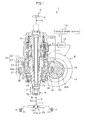
- FIG. 2A is an enlarged sectional view of an important part of the worm speed reducer 15.
- the worm wheel 30 includes an annular tooth portion 32 formed of resin and having an outer periphery 32a on which teeth 31 are annularly arranged and an annular support 33 formed of metal.
- the annular support 33 is, for example, inserted into a mold when the annular tooth portion 32 is molded from the resin.
- the annular support 33 includes an outer periphery 33a that supports an inner periphery 32b of the annular tooth portion 32 and an inner periphery 33b with which an outer periphery 72a of the output shaft 72 is press-fitted.
- the output shaft 72 of the column shaft 7 is formed of, for example, iron, whereas the annular support 33 is formed of a metal material that is softer than the metal material, e.g., iron or an iron alloy, forming the output shaft 72.
- Examples of the metal material forming the annular support 33 include aluminum, an aluminum alloy, magnesium, and a magnesium alloy.
- the linear thermal expansion coefficient of the metal material forming the annular support 33 is different from the linear thermal expansion coefficient of the metal material forming the output shaft 72. Specifically, the linear thermal expansion coefficient of the metal material forming the annular support 33 is larger than the linear thermal expansion coefficient of the metal material forming the output shaft 72.
- the ring member 40 includes a tubular ring member main body 41, and a flange 42 extending radially outward from one end 411 of the ring member main body 41 to engage with an axial end surface 33c of the annular support 33.
- the flange 42 may be annular or may be formed on a part of the ring member 40 in a circumferential direction.
- the ring member 40 includes: an outer periphery 40a (corresponding to the outer periphery of the ring member main body 41) press-fitted with the inner periphery 33b of the annular support 33; and an inner periphery 40b (corresponding to the inner periphery of the ring member main body 41) with which the outer periphery 72a of the output shaft 72 is press-fitted.
- the ring member 40 is formed of a metal material with a hardness equivalent to the hardness of the output shaft 72, for example, iron or an iron alloy.
- the inner periphery 40b of the ring member 40 and the outer periphery 72a of the output shaft 72 provide a torque limiter TL that allows the ring member 40 and the output shaft 72 to slide with respect to each other when a torque exceeding a limit torque is input.
- FIG. 2B is a schematic cross-sectional view of a press fitting portion between the ring member 40 and the annular support 33.
- the outer periphery 40a of the ring member 40 is press-fitted with the inner periphery 33b of the annular support 33 so as to form plastically deformed portions 34 in part of the inner periphery 33b of the annular support 33.
- a serration 43 is provided on the outer periphery 40a of the ring member 40.
- the serration 43 includes multiple protruding portions 43a separated from one another in the circumferential direction of the outer periphery 40a of the ring member 40.
- Respective tops 43b of the protruding portions 43a cut into the inner periphery 33b of the annular support 33 to form the plastically deformed portions 34 in the inner periphery 33b of the annular support 33. That is, the plastically deformed portions 34 are formed in part of the inner periphery 33b of the annular support 33 so as to be separated from one another in the circumferential direction of the inner periphery 33b of the annular support 33.
- the outer periphery 40a of the ring member 40 is press-fitted with the inner periphery 33b of the annular support 33 formed of the material softer than the material of the ring member 40, so as to form the plastically deformed portions 34 in part of the inner periphery 33b of the annular support 33. Therefore, when the worm speed reducer 15 is assembled, possible seizure resulting from the press-in of the ring member 40 against the annular support 33 is inhibited. This allows inhibition of inappropriate assembly of the worm speed reducer 15 and therefore inappropriate assembly of the electric power steering system 1.
- a plastic flow of a surface layer of the member of the soft material has nowhere to escape at the time of press-in, leading to the risk of seizure.
- the ring member 40 of the hard material is press-fitted with the inner periphery 33b of the annular support 33 of the soft material so as to form the plastically deformed portions 34 in part of the inner periphery 33b in the circumferential direction.
- the ring member 40 is preferably pressed in against the inner periphery 33b of the annular support 33 before the output shaft 72 is pressed in. This is because the inner periphery of the ring member 40 is not restrained and the ring member 40 can thus be easily reduced in diameter at the time of press-in, allowing possible seizure to be further inhibited.
- the output shaft 72 and the ring member 40 have an equivalent hardness and are unsusceptible to seizure when press-fitted together.
- the fitting surfaces of the output shaft 72 and the ring member 40 which have an equivalent hardness, provide the torque limiter TL. That is, when an overtorque is input, the outer periphery 72a of the output shaft 72 and the inner periphery 40b of the ring member 40 slide with respect to each other, limiting a transmitted torque to the limit torque or lower. Thus, possible damage to the teeth 31 of the worm wheel 30 can be prevented, allowing the steering function to be maintained.
- the linear thermal expansion coefficient of the ring member 40 is equivalent to the linear thermal expansion coefficient of the output shaft 72. Therefore, even with a change in temperature, the tightening margin between the ring member 40 and the output shaft 72 is unchanged. This prevents a possible change in sliding torque (corresponding to the limit torque for the torque limiter TL) between the ring member 40 and the output shaft 72 and a possible change in sliding load between the ring member 40 and the output shaft 72 in the axial direction X.
- the ring member 40 formed of the harder material than the annular support 33 is fitted with the inner periphery 33b of the annular support 33 such that the serration 43 on the outer periphery 40a of the ring member 40 forms the plastically deformed portions in part of the inner periphery 33b of the annular support 33.
- the tightening margin between the outer periphery 40a of the ring member 40 and the inner periphery 33b of the annular support 33 is changed due to a change in temperature, the change in the tightening margin can be absorbed by the serration fitting area. This allows inhibition of sliding of the outer periphery 40a of the ring member 40 and the inner periphery 33b of the annular support 33 with respect to each other in the rotating direction.
- the flange 42 provided on the ring member 40 engages with the axial end surface 33c of the annular support 33 to allow prevention of sliding of the ring member 40 and the annular support 33 with respect to each other in the axial direction.
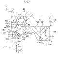
- FIG. 3 depicts a second embodiment of the present invention.
- the second embodiment in FIG. 3 is different from the first embodiment in FIG. 2A mainly in the following. That is, as the ring member interposed between the outer periphery 72a of the output shaft 72 and the inner periphery 33b of the annular support 33 of the worm wheel 30, a pair of ring members 50 and 60 is provided. The ring members 50 and 60 face each other, as depicted in FIG. 3 .
- the ring members 50 and 60 include ring member main bodies 51 and 61 corresponding to the ring member main body 41 in the first embodiment in FIG. 2A and flanges 52 and 62 corresponding to the flange 42 in the first embodiment in FIG. 2A .
- Outer peripheries 50a and 60a (corresponding to the outer peripheries of the ring member main bodies 51 and 61) of the ring members 50 and 60 are press-fitted with the inner periphery 33b of the annular support 33 so as to form plastically deformed portions (corresponding to the same configuration as that in FIG. 2B though this is not depicted in the drawings) in part of the inner periphery 33b.
- the outer periphery 72a of the output shaft 72 is press-fitted with inner peripheries 50b and 60b (corresponding to the inner peripheries of the ring member main bodies 51 and 61) of the ring members 50 and 60.
- the ring member main bodies 51 and 61 of the ring members 50 and 60 have first ends 511 and 611 serving as facing ends that face each other in the axial direction X, and second ends 512 and 612 opposite from the first ends 511 and 611, respectively.
- the ring members 50 and 60 are pressed in against the inner periphery 33b of the annular support 33 so as to place the first ends 511 and 611 (facing ends) of the ring members 50 and 60 face each other. That is, the ring member 50 is pressed in in one direction X1 along the axial direction X, and the ring member 60 is pressed in in the other direction X2 along the axial direction X.
- a gap space CS is formed between the first ends 511 and 611 (facing ends) of the ring member main bodies 51 and 61 of the ring members 50 and 60.
- the gap space CS is defined by the outer periphery 72a of the output shaft 72, the inner periphery 33b of the annular support 33, and the first ends 511 and 611 of the ring member main bodies 51 and 61 of the ring members 50 and 60.
- the flanges 52 and 62 extend from the second ends 512 and 612 of the ring member main bodies 51 and 61, respectively, and engage with the axial end surfaces 33d and 33c, respectively, of the annular support 33.
- the second embodiment can produce the same advantageous effects as those of the first embodiment.
- the ring members 50 and 60 are externally press-fitted with the inner periphery 33b of the annular support 33 from the opposite sides in the axial direction X.
- the flanges 52 and 62 of the ring members 50 and 60 engage with the axial end surfaces 33d and 33c, respectively, of the annular support 33 to allow prevention of sliding of the ring members 50 and 60 and the annular support 33 in the axial direction X.
- chips resulting from external press fitting of the ring members 50 and 60 in the output shaft 72 can be housed in the gap space CS between the ring members 50 and 60. If the gap where the chips escape is not present between the ring members 50 and 60, then the chips are collected between the ring members 50 and 60, with a corresponding amount of axial gap formed between the annular support 33 and the flanges 52 and 62 of the ring members 50 and 60. This may lead to a situation where the flanges 52 and 62 of the ring members 50 and 60 fail to prevent axial sliding of the annular support 33. In contrast, in the present invention, the gap space CS where the chips escape is formed between the ring members 50 and 60, allowing the above-described situation to be inhibited.
- a plurality of protruding portions (not depicted in the drawings) separated from one another in the circumferential direction may be provided on the outer periphery of the ring member in order to form plastically deformed portions in part of the inner periphery of the annular support.
- keys (not depicted in the drawings) held in axial grooves in the outer periphery of the ring member may be pressed in against the inner periphery of the ring member to form plastically deformed portions in part of the inner periphery.
- the present invention may be applied to an electric power steering system of a type in which a driving force of the electric motor is transmitted to the pinion shaft.
- the pinion shaft includes an input shaft coupled to the intermediate shaft side, an output shaft forming a pinion, and a torsion bar coaxially coupling the input shaft and the output shaft together.
- the ring member is press-fitted with the outer periphery of the output shaft, and the inner periphery of the annular support of the worm wheel is press-fitted with the outer periphery of the ring member.
Landscapes
- Engineering & Computer Science (AREA)
- General Engineering & Computer Science (AREA)
- Mechanical Engineering (AREA)
- Chemical & Material Sciences (AREA)
- Combustion & Propulsion (AREA)
- Transportation (AREA)
- Power Steering Mechanism (AREA)
- Gear Transmission (AREA)
Abstract

Description
- The present invention relates to an electric power steering system.
- In general, in known electric power steering systems that transmit a motor torque via a worm speed reducer, a gear portion of a resin material integrated with an outer periphery of a cored bar portion of an iron material is used as a worm wheel.
- In recent years, the size of the worm wheel has tended to increase with an increase in mechanical output power of the electric power steering system. Consequently, the size and thus the weight of the cored bar portion increase. This may increase an inertia force exerted at the time of steering to degrade a steering feeling.
- Thus, an electric power steering system has been developed, which uses aluminum or the like with a lower specific gravity than iron, as the cored bar portion of the worm wheel. In a technique described in Japanese Patent Application Publication No.
2002-2509 JP 2002-2509 A - Japanese Patent Application Publication No.
2001-271903 JP 2001-271903 A - If an outer periphery defined by a cylindrical surface of the iron shaft and an inner periphery defined by a cylindrical surface of the cored bar formed of a material softer than iron, for example, aluminum, are entirely press-fitted together along a circumferential direction, the press-fitted surfaces may seize, leading to inappropriate assembly.
- This is considered to be because, at the time of press-in, a plastic flow of a surface layer of the soft material member causes a fresh surface to be exposed, resulting in metallic contact between the hard material and the soft material. In particular, when the hard material and the soft material are entirely press-fitted together along the circumferential direction, plastically deformed portions resulting from the plastic flow have nowhere to escape. The plastically deformed portions cut into the press-fitted surface, resulting in a high likelihood of metallic contact and thus seizure.
- An object of the present invention is to provide an electric power steering system that allows inhibition of inappropriate assembly caused by seizure at the time of press-in.
- An electric power steering system according to an aspect of the present invention includes a shaft that transmits a steering force, an electric motor for steering assistance, and a worm speed reducer that reduces a speed of rotation output from the electric motor and transmits the rotation to the shaft.
- The worm speed reducer includes a worm shaft that is rotationally driven by the electric motor, a worm wheel having an annular tooth portion with an outer periphery on which teeth are annularly arranged and an annular support that supports an inner periphery of the annular tooth portion and that is formed of a material softer than a material of the shaft, and a ring member having an outer periphery press-fitted with an inner periphery of the annular support so as to form a plastically deformed portion in part of the inner periphery of the annular support, and an inner periphery with which an outer periphery of the shaft is press-fitted, the ring member formed of a material with a hardness equivalent to a hardness of the material of the shaft.
- In the electric power steering system in the above-described aspect, at the time of assembly, the outer periphery of the ring portion is press-fitted with the inner periphery of the annular support so as to form the plastically deformed portion in part of the inner periphery of the annular support. Thus, possible seizure can be inhibited at the time of press-in, allowing inappropriate assembly to be inhibited. The shaft and the ring member have an equivalent hardness and are thus unlikely to seize when press-fitted together.
- In the electric power steering system in the above-described aspect, the inner periphery of the ring member and the outer periphery of the shaft may provide a torque limiter that allows the ring member and the shaft to slide with respect to each other when a torque exceeding a limit torque is input.
- In the electric power steering system in the above-described aspect, when an overtorque is input, the shaft and the ring member slide with respect to each other, limiting a transmitted torque to the limit torque or lower. Thus, the teeth can be prevented from being damaged, allowing a steering function to be ensured.
- In the electric power steering system in the above-described aspect, a linear thermal expansion coefficient of the ring member may be equivalent to that of the shaft.
- In the electric power steering system in the above-described aspect, a tightening margin between the ring member and the shaft does not change even with a change in temperature. Therefore, this prevents a possible change in sliding torque (corresponding to the limit torque of the torque limiter) between the ring member and the shaft and a possible change in axial sliding load between the ring member and the shaft.
- In the electric power steering system in the above-described aspect, the linear thermal expansion coefficient of the ring member may be different from that of the annular support, and a serration may be provided on the outer periphery of the ring member.
- In the electric power steering system in the above-described aspect, the outer peripheral serration of the ring member, formed of the material harder than the material of the annular support, is press-fitted with the inner periphery of the annular support so as to form the plastically deformed portions in part of the inner periphery of the annular support. Therefore, even when the tightening margin between the outer periphery of the ring member and the inner periphery of the annular support is changed due to a change in temperature, the change in tightening margin can be absorbed by the serration fitting area. This allows inhibition of sliding of the outer periphery of the ring member and the inner periphery of the annular support with respect to each other in a rotating direction.
- In the electric power steering system in the above-described aspect, the ring member may include a flange that engages with an axial end surface of the annular support.
- In the electric power steering system in the above-described aspect, the flange of the ring member engages with the axial end surface of the annular support to allow prevention of axial sliding of the ring member and the annular support with respect to each other.
- In the electric power steering system in the above-described aspect, as the ring member, a pair of ring members may be included, the ring members facing each other in an axial direction. Ring member main bodies of the ring members may include respective first ends facing each other in the axial direction and respective second ends each opposite from the corresponding first end. The flange may extend radially outward from the second end of each of the ring member main bodies to engage with the corresponding axial end surface of the annular support.
- In the electric power steering system in the above-described aspect, the flange of each of the ring members engages with the corresponding axial end surface of the annular support to allow prevention of axial sliding of the ring member and the annular support with respect to each other.
- In the electric power steering system in the above-described aspect, a gap space may be formed between the first ends of the ring members.
- In the electric power steering system in the above-described aspect, chips resulting from external press fitting of the ring members with the shaft can be housed in the gap space between the ring members. If the gap that serves as a place where chips escape is not present between the ring members, the chips are collected between the ring members, with a corresponding amount of axial gap formed between the flange of the ring member and the annular support. This may lead to a situation where the flanges of the ring members fail to prevent axial sliding of the annular support. In contrast, in the electric power steering system in the above-described aspect, the gap space where the chips escape is formed between the ring members, allowing the above-described situation to be prevented.
- The foregoing and further features and advantages of the invention will become apparent from the following description of example embodiments with reference to the accompanying drawings, wherein like numerals are used to represent like elements and wherein:
-
FIG. 1 is a schematic diagram of an electric power steering system in a first embodiment of the present embodiment including a section of the electric power steering system; -
FIG. 2A is an enlarged view of an important part of a worm speed reducer in the electric power steering system; -
FIG. 2B is a schematic sectional view of a press fitting portion between an annular support of a worm wheel and a ring member; and -
FIG. 3 is an enlarged sectional view of an important part of a worm speed reducer in an electric power steering system in a second embodiment of the present invention. - Embodiments of the present invention will be described below with reference to the attached drawings.
-
FIG. 1 is a schematic diagram depicting a general configuration of an electric power steering system according to a first embodiment of the present invention. As depicted inFIG. 1 , an electric power steering system 1 includes asteering mechanism 4 that steers steeredwheels 3 based on a driver's operation of asteering wheel 2, and anassist mechanism 5 that assists the driver's steering operation. - The
steering mechanism 4 includes asteering shaft 6 that serves as a rotating shaft for asteering wheel 2. Thesteering shaft 6 includes acolumn shaft 7 connected to a center of thesteering wheel 2, anintermediate shaft 9 coupled to one end (axially lower end) of thecolumn shaft 7 via auniversal joint 8, and apinion shaft 11 coupled to one end (axially lower end) of theintermediate shaft 9 via auniversal joint 10. - The
column shaft 7 includes aninput shaft 71 coupled to thesteering wheel 2, anoutput shaft 72 coupled to theintermediate shaft 9, and atorsion bar 73 that coaxially couples theinput shaft 71 and theoutput shaft 72 together. - A
pinion 11 a is provided at an axially lower end of thepinion shaft 11. Thesteering mechanism 4 includes arack shaft 12 on which arack 12a meshing with thepinion 11a is formed. Thepinion 11a and therack 12a form a rack-and-pinion mechanism A that is a motion converting mechanism. - When the
steering shaft 6 rotates in conjunction with the driver's steering operation, a rotary motion of thesteering shaft 6 is converted, via the rack and pinion mechanism A, into a reciprocating linear motion of therack shaft 12 in an axial direction thereof. The reciprocating linear motion of therack shaft 12 is transmitted to steeredwheels 3 viatie rods 13 coupled to opposite ends of therack shaft 12. Thus, steered angles of the steeredwheels 3 are changed to change the traveling direction of the vehicle. - The
assist mechanism 5 includes anelectric motor 14 that applies an assist torque to thecolumn shaft 7, aworm speed reducer 15 that transmits rotation of theelectric motor 14 to thecolumn shaft 7, and an electronic control unit (ECU) 16 that controls operations of theelectric motor 14. - The rotation of the
electric motor 14 is transmitted to thecolumn shaft 7 via theworm speed reducer 15 to apply a motor torque to thesteering shaft 6, thus assisting the steering operation. - The electric power steering system 1 is provided with a torque sensor 17 that detects a steering torque T that is a torque applied to the
steering shaft 6 when the driver performs the steering operation, based on relative rotation of theinput shaft 71 and theoutput shaft 72 of thecolumn shaft 7. The vehicle is provided with avehicle speed sensor 18 that detects a vehicle speed V (traveling speed of the vehicle). - The
ECU 16 sets a target assist force based on the detected steering torque T and the detected vehicle speed V, and feedback-controls a current supplied to theelectric motor 14 so as to make the assist torque applied to thecolumn shaft 7 by theelectric motor 14 equal to a target assist torque. - The present embodiment will be described with reference to an example where the electric power steering system 1 is of what is called a column assist type in which the
electric motor 14 applies an assist force to thecolumn shaft 7. However, the present invention is not limited to this, but is applicable to an electric power steering system of what is called a pinion assist type in which the electric motor applies the assist force to the pinion shaft. - The
worm speed reducer 15 includes aworm shaft 20 rotationally driven by theelectric motor 14, aworm wheel 30 that meshes with aworm 20a on an outer periphery of theworm shaft 20, and aring member 40 interposed between theoutput shaft 72 of thecolumn shaft 7 and theworm wheel 30. - The
worm wheel 30 is coupled to theoutput shaft 72 of thecolumn shaft 7 via thering member 40. Theworm wheel 30 and thecolumn shaft 7 integrally rotate and are precluded from moving in the axial direction relative to each other. - A part of the
column shaft 7 is housed in and supported by ahousing 21 that provides a part of a steering column. Thehousing 21 includes afirst housing 22 and asecond housing 23 that are fitted together. - The
first housing 22 functions as a sensor housing in which the torque sensor 17 is housed. Thesecond housing 23 functions as a gear housing in which theworm shaft 20 and theworm wheel 30 are housed. - The
output shaft 72 of thecolumn shaft 7 is rotatably supported via afirst bearing 24 held by thefirst housing 22 and asecond bearing 25 held by thesecond housing 23. Thefirst bearing 24 and thesecond bearing 25 are, for example, ball bearings. Theworm wheel 30 is arranged between thefirst bearing 24 and thesecond bearing 25 with respect to an axial direction X of theoutput shaft 72. -
FIG. 2A is an enlarged sectional view of an important part of theworm speed reducer 15. As depicted inFIG. 1 andFIG. 2A , theworm wheel 30 includes anannular tooth portion 32 formed of resin and having anouter periphery 32a on whichteeth 31 are annularly arranged and anannular support 33 formed of metal. Theannular support 33 is, for example, inserted into a mold when theannular tooth portion 32 is molded from the resin. - As depicted in
FIG. 2A , theannular support 33 includes anouter periphery 33a that supports aninner periphery 32b of theannular tooth portion 32 and aninner periphery 33b with which anouter periphery 72a of theoutput shaft 72 is press-fitted. - The
output shaft 72 of thecolumn shaft 7 is formed of, for example, iron, whereas theannular support 33 is formed of a metal material that is softer than the metal material, e.g., iron or an iron alloy, forming theoutput shaft 72. - Examples of the metal material forming the
annular support 33 include aluminum, an aluminum alloy, magnesium, and a magnesium alloy. The linear thermal expansion coefficient of the metal material forming theannular support 33 is different from the linear thermal expansion coefficient of the metal material forming theoutput shaft 72. Specifically, the linear thermal expansion coefficient of the metal material forming theannular support 33 is larger than the linear thermal expansion coefficient of the metal material forming theoutput shaft 72. - The
ring member 40 includes a tubular ring membermain body 41, and aflange 42 extending radially outward from oneend 411 of the ring membermain body 41 to engage with anaxial end surface 33c of theannular support 33. Theflange 42 may be annular or may be formed on a part of thering member 40 in a circumferential direction. - The
ring member 40 includes: anouter periphery 40a (corresponding to the outer periphery of the ring member main body 41) press-fitted with theinner periphery 33b of theannular support 33; and aninner periphery 40b (corresponding to the inner periphery of the ring member main body 41) with which theouter periphery 72a of theoutput shaft 72 is press-fitted. Thering member 40 is formed of a metal material with a hardness equivalent to the hardness of theoutput shaft 72, for example, iron or an iron alloy. - The
inner periphery 40b of thering member 40 and theouter periphery 72a of theoutput shaft 72 provide a torque limiter TL that allows thering member 40 and theoutput shaft 72 to slide with respect to each other when a torque exceeding a limit torque is input. -
FIG. 2B is a schematic cross-sectional view of a press fitting portion between thering member 40 and theannular support 33. As depicted inFIG. 2B , theouter periphery 40a of thering member 40 is press-fitted with theinner periphery 33b of theannular support 33 so as to form plasticallydeformed portions 34 in part of theinner periphery 33b of theannular support 33. - Specifically, a
serration 43 is provided on theouter periphery 40a of thering member 40. Theserration 43 includes multiple protrudingportions 43a separated from one another in the circumferential direction of theouter periphery 40a of thering member 40. Respective tops 43b of the protrudingportions 43a cut into theinner periphery 33b of theannular support 33 to form the plasticallydeformed portions 34 in theinner periphery 33b of theannular support 33. That is, the plasticallydeformed portions 34 are formed in part of theinner periphery 33b of theannular support 33 so as to be separated from one another in the circumferential direction of theinner periphery 33b of theannular support 33. - In the present embodiment, the
outer periphery 40a of thering member 40 is press-fitted with theinner periphery 33b of theannular support 33 formed of the material softer than the material of thering member 40, so as to form the plasticallydeformed portions 34 in part of theinner periphery 33b of theannular support 33. Therefore, when theworm speed reducer 15 is assembled, possible seizure resulting from the press-in of thering member 40 against theannular support 33 is inhibited. This allows inhibition of inappropriate assembly of theworm speed reducer 15 and therefore inappropriate assembly of the electric power steering system 1. - That is, if a member of a hard material is press-fitted with a fitting surface of a member of a soft material so as to form a plastically deformed portion over the entire fitting surface along the circumferential direction, a plastic flow of a surface layer of the member of the soft material has nowhere to escape at the time of press-in, leading to the risk of seizure.
- In contrast, in the present embodiment, the
ring member 40 of the hard material is press-fitted with theinner periphery 33b of theannular support 33 of the soft material so as to form the plasticallydeformed portions 34 in part of theinner periphery 33b in the circumferential direction. Thus, at the time of press-in, a place where the plastic flow of the surface layer of theinner periphery 33b of theannular support 33 escapes is easily secured, allowing possible seizure to be inhibited. - The
ring member 40 is preferably pressed in against theinner periphery 33b of theannular support 33 before theoutput shaft 72 is pressed in. This is because the inner periphery of thering member 40 is not restrained and thering member 40 can thus be easily reduced in diameter at the time of press-in, allowing possible seizure to be further inhibited. - The
output shaft 72 and thering member 40 have an equivalent hardness and are unsusceptible to seizure when press-fitted together. - The fitting surfaces of the
output shaft 72 and thering member 40, which have an equivalent hardness, provide the torque limiter TL. That is, when an overtorque is input, theouter periphery 72a of theoutput shaft 72 and theinner periphery 40b of thering member 40 slide with respect to each other, limiting a transmitted torque to the limit torque or lower. Thus, possible damage to theteeth 31 of theworm wheel 30 can be prevented, allowing the steering function to be maintained. - The linear thermal expansion coefficient of the
ring member 40 is equivalent to the linear thermal expansion coefficient of theoutput shaft 72. Therefore, even with a change in temperature, the tightening margin between thering member 40 and theoutput shaft 72 is unchanged. This prevents a possible change in sliding torque (corresponding to the limit torque for the torque limiter TL) between thering member 40 and theoutput shaft 72 and a possible change in sliding load between thering member 40 and theoutput shaft 72 in the axial direction X. - As depicted in
FIG. 2B , thering member 40 formed of the harder material than theannular support 33 is fitted with theinner periphery 33b of theannular support 33 such that theserration 43 on theouter periphery 40a of thering member 40 forms the plastically deformed portions in part of theinner periphery 33b of theannular support 33. Even when the tightening margin between theouter periphery 40a of thering member 40 and theinner periphery 33b of theannular support 33 is changed due to a change in temperature, the change in the tightening margin can be absorbed by the serration fitting area. This allows inhibition of sliding of theouter periphery 40a of thering member 40 and theinner periphery 33b of theannular support 33 with respect to each other in the rotating direction. - The
flange 42 provided on thering member 40 engages with theaxial end surface 33c of theannular support 33 to allow prevention of sliding of thering member 40 and theannular support 33 with respect to each other in the axial direction. -
FIG. 3 depicts a second embodiment of the present invention. The second embodiment inFIG. 3 is different from the first embodiment inFIG. 2A mainly in the following. That is, as the ring member interposed between theouter periphery 72a of theoutput shaft 72 and theinner periphery 33b of theannular support 33 of theworm wheel 30, a pair ofring members ring members FIG. 3 . - Specifically, the
ring members main bodies main body 41 in the first embodiment inFIG. 2A andflanges flange 42 in the first embodiment inFIG. 2A . -
Outer peripheries main bodies 51 and 61) of thering members inner periphery 33b of theannular support 33 so as to form plastically deformed portions (corresponding to the same configuration as that inFIG. 2B though this is not depicted in the drawings) in part of theinner periphery 33b. Theouter periphery 72a of theoutput shaft 72 is press-fitted withinner peripheries main bodies 51 and 61) of thering members - The ring member
main bodies ring members - The
ring members inner periphery 33b of theannular support 33 so as to place the first ends 511 and 611 (facing ends) of thering members ring member 50 is pressed in in one direction X1 along the axial direction X, and thering member 60 is pressed in in the other direction X2 along the axial direction X. - A gap space CS is formed between the first ends 511 and 611 (facing ends) of the ring member
main bodies ring members outer periphery 72a of theoutput shaft 72, theinner periphery 33b of theannular support 33, and the first ends 511 and 611 of the ring membermain bodies ring members - The
flanges main bodies annular support 33. - The same components of the second embodiment in
FIG. 3 as the corresponding components of the first embodiment inFIG. 2A are denoted by the same reference numerals as the corresponding reference numerals of the first embodiment inFIG. 2A . - The second embodiment can produce the same advantageous effects as those of the first embodiment. Moreover, the
ring members inner periphery 33b of theannular support 33 from the opposite sides in the axial direction X. Theflanges ring members annular support 33 to allow prevention of sliding of thering members annular support 33 in the axial direction X. - Furthermore, chips resulting from external press fitting of the
ring members output shaft 72 can be housed in the gap space CS between thering members ring members ring members annular support 33 and theflanges ring members flanges ring members annular support 33. In contrast, in the present invention, the gap space CS where the chips escape is formed between thering members - The present invention is not limited to the above-described embodiments. For example, instead of the serration formed on the outer periphery of the ring member, a plurality of protruding portions (not depicted in the drawings) separated from one another in the circumferential direction may be provided on the outer periphery of the ring member in order to form plastically deformed portions in part of the inner periphery of the annular support. Alternatively, keys (not depicted in the drawings) held in axial grooves in the outer periphery of the ring member may be pressed in against the inner periphery of the ring member to form plastically deformed portions in part of the inner periphery.
- The present invention may be applied to an electric power steering system of a type in which a driving force of the electric motor is transmitted to the pinion shaft. In that case, the pinion shaft includes an input shaft coupled to the intermediate shaft side, an output shaft forming a pinion, and a torsion bar coaxially coupling the input shaft and the output shaft together. The ring member is press-fitted with the outer periphery of the output shaft, and the inner periphery of the annular support of the worm wheel is press-fitted with the outer periphery of the ring member.
Claims (7)
- An electric power steering system comprising:a shaft that transmits a steering force;an electric motor for steering assistance; anda worm speed reducer that reduces a speed of rotation output from the electric motor and transmits the rotation to the shaft; whereinthe worm speed reducer includes:a worm shaft that is rotationally driven by the electric motor;a worm wheel having an annular tooth portion with an outer periphery on which teeth are annularly arranged and an annular support that supports an inner periphery of the annular tooth portion and that is formed of a material softer than a material of the shaft; anda ring member having an outer periphery press-fitted with an inner periphery of the annular support so as to form a plastically deformed portion in part of the inner periphery of the annular support, and an inner periphery with which an outer periphery of the shaft is press-fitted, the ring member formed of a material with a hardness equivalent to a hardness of the material of the shaft.
- The electric power steering system according to claim 1, wherein the inner periphery of the ring member and the outer periphery of the shaft provide a torque limiter that allows the ring member and the shaft to slide with respect to each other when a torque exceeding a limit torque is input.
- The electric power steering system according to claim 1 or 2, wherein a linear thermal expansion coefficient of the ring member is equivalent to that of the shaft.
- The electric power steering system according to any one of claims 1 to 3, wherein the linear thermal expansion coefficient of the ring member is different from that of the annular support, and
a serration is provided on the outer periphery of the ring member. - The electric power steering system according to any one of claims 1 to 4, wherein the ring member includes a ring member main body and a flange that extends radially outward from the ring member main body to engage with an axial end surface of the annular support.
- The electric power steering system according to claim 5, wherein
as the ring member, a pair of ring members is included, the ring members facing each other in an axial direction,
ring member main bodies of the ring members include respective first ends facing each other in the axial direction and respective second ends each opposite from the corresponding first end, and
the flange extends radially outward from the second end of each of the ring member main bodies to engage with the corresponding axial end surface of the annular support. - The electric power steering system according to claim 6, wherein
a gap space is formed between the first ends of the ring members.
Applications Claiming Priority (1)
| Application Number | Priority Date | Filing Date | Title |
|---|---|---|---|
| JP2014141652A JP2016016789A (en) | 2014-07-09 | 2014-07-09 | Electric power steering device |
Publications (2)
| Publication Number | Publication Date |
|---|---|
| EP2965971A2 true EP2965971A2 (en) | 2016-01-13 |
| EP2965971A3 EP2965971A3 (en) | 2016-02-10 |
Family
ID=53510768
Family Applications (1)
| Application Number | Title | Priority Date | Filing Date |
|---|---|---|---|
| EP15175227.6A Withdrawn EP2965971A3 (en) | 2014-07-09 | 2015-07-03 | Electric power steering system |
Country Status (4)
| Country | Link |
|---|---|
| US (1) | US9580101B2 (en) |
| EP (1) | EP2965971A3 (en) |
| JP (1) | JP2016016789A (en) |
| CN (1) | CN105313950A (en) |
Families Citing this family (3)
| Publication number | Priority date | Publication date | Assignee | Title |
|---|---|---|---|---|
| US20170361867A1 (en) * | 2016-06-20 | 2017-12-21 | Dura Operating, Llc | Steering input sensor for a steer-by-wire assembly |
| CN110185772A (en) * | 2019-06-21 | 2019-08-30 | 南京高速齿轮制造有限公司 | Wind turbine gearbox spline Axile connection structure |
| CN110185782A (en) * | 2019-06-24 | 2019-08-30 | 南京高速齿轮制造有限公司 | The planet carrier and main shaft connection structure of wind turbine gearbox |
Citations (2)
| Publication number | Priority date | Publication date | Assignee | Title |
|---|---|---|---|---|
| JP2001271903A (en) | 2000-01-17 | 2001-10-05 | Honda Motor Co Ltd | Power transmission device for work equipment |
| JP2002002509A (en) | 2000-06-19 | 2002-01-09 | Nsk Ltd | Electric power steering device |
Family Cites Families (8)
| Publication number | Priority date | Publication date | Assignee | Title |
|---|---|---|---|---|
| JPH11139326A (en) * | 1997-11-10 | 1999-05-25 | Koyo Seiko Co Ltd | Electrically-driven power steering device |
| JP4275833B2 (en) * | 2000-01-13 | 2009-06-10 | 株式会社ショーワ | Electric power steering device |
| GB2369872B (en) * | 2000-06-19 | 2004-10-20 | Nsk Ltd | Motor-driven power steering device |
| JP3765232B2 (en) | 2000-11-16 | 2006-04-12 | 株式会社ジェイテクト | Electric power steering apparatus and gear manufacturing method used therefor |
| JP2003207029A (en) | 2002-01-11 | 2003-07-25 | Koyo Seiko Co Ltd | Reduction gear system and electric power steering device |
| US7930950B2 (en) * | 2005-01-25 | 2011-04-26 | Showa Corporation | Motor-driven steering assist apparatus |
| JP5181483B2 (en) | 2007-01-26 | 2013-04-10 | 株式会社ジェイテクト | Gear and electric power steering device |
| WO2009123254A1 (en) * | 2008-04-04 | 2009-10-08 | Ntn株式会社 | Wheel bearing apparatus and axle module |
-
2014
- 2014-07-09 JP JP2014141652A patent/JP2016016789A/en active Pending
-
2015
- 2015-06-30 US US14/755,391 patent/US9580101B2/en not_active Expired - Fee Related
- 2015-07-03 EP EP15175227.6A patent/EP2965971A3/en not_active Withdrawn
- 2015-07-08 CN CN201510397853.8A patent/CN105313950A/en active Pending
Patent Citations (2)
| Publication number | Priority date | Publication date | Assignee | Title |
|---|---|---|---|---|
| JP2001271903A (en) | 2000-01-17 | 2001-10-05 | Honda Motor Co Ltd | Power transmission device for work equipment |
| JP2002002509A (en) | 2000-06-19 | 2002-01-09 | Nsk Ltd | Electric power steering device |
Also Published As
| Publication number | Publication date |
|---|---|
| CN105313950A (en) | 2016-02-10 |
| US20160009313A1 (en) | 2016-01-14 |
| EP2965971A3 (en) | 2016-02-10 |
| US9580101B2 (en) | 2017-02-28 |
| JP2016016789A (en) | 2016-02-01 |
Similar Documents
| Publication | Publication Date | Title |
|---|---|---|
| EP2559607B1 (en) | Electric power steering device | |
| JP5999423B2 (en) | Electric power steering device | |
| EP2431634B1 (en) | Worm drive | |
| EP2351681B1 (en) | Motorized power steering device | |
| JP4385286B2 (en) | Electric power steering device | |
| EP3441645B1 (en) | Worm reducer | |
| WO2017010345A1 (en) | Dual-pinion electric power steering device | |
| JP6887498B2 (en) | Steering transmission mechanism and steering system | |
| US9580101B2 (en) | Electric power steering system | |
| KR20170027170A (en) | Steering Column for Vehicle | |
| EP3643582A1 (en) | Shaft for steering device, method for manufacturing shaft for steering device, and electric power steering device | |
| JP2015160493A (en) | power steering device | |
| JP2011117496A (en) | Spline telescopic shaft | |
| EP1813507B1 (en) | Electric power steering apparatus | |
| JP2011255818A (en) | Electric power steering device | |
| JP2005205923A (en) | Electric power steering device | |
| JP4085867B2 (en) | Worm support device and electric power steering device | |
| JP2007050845A (en) | Electric power steering device | |
| JP4936958B2 (en) | Torque sensor | |
| JP2010149574A (en) | Electric power steering device | |
| JP4352325B2 (en) | Electric power steering device | |
| EP3088771B1 (en) | Worm shaft subassembly | |
| JP2012106560A (en) | Electric power steering device | |
| JP2007064323A (en) | Shaft for constant velocity universal joint | |
| JP2001233224A (en) | Electric power steering device |
Legal Events
| Date | Code | Title | Description |
|---|---|---|---|
| PUAL | Search report despatched |
Free format text: ORIGINAL CODE: 0009013 |
|
| PUAI | Public reference made under article 153(3) epc to a published international application that has entered the european phase |
Free format text: ORIGINAL CODE: 0009012 |
|
| AK | Designated contracting states |
Kind code of ref document: A2 Designated state(s): AL AT BE BG CH CY CZ DE DK EE ES FI FR GB GR HR HU IE IS IT LI LT LU LV MC MK MT NL NO PL PT RO RS SE SI SK SM TR |
|
| AX | Request for extension of the european patent |
Extension state: BA ME |
|
| AK | Designated contracting states |
Kind code of ref document: A3 Designated state(s): AL AT BE BG CH CY CZ DE DK EE ES FI FR GB GR HR HU IE IS IT LI LT LU LV MC MK MT NL NO PL PT RO RS SE SI SK SM TR |
|
| AX | Request for extension of the european patent |
Extension state: BA ME |
|
| RIC1 | Information provided on ipc code assigned before grant |
Ipc: B62D 5/04 20060101AFI20160104BHEP |
|
| 17P | Request for examination filed |
Effective date: 20160314 |
|
| RBV | Designated contracting states (corrected) |
Designated state(s): AL AT BE BG CH CY CZ DE DK EE ES FI FR GB GR HR HU IE IS IT LI LT LU LV MC MK MT NL NO PL PT RO RS SE SI SK SM TR |
|
| STAA | Information on the status of an ep patent application or granted ep patent |
Free format text: STATUS: THE APPLICATION IS DEEMED TO BE WITHDRAWN |
|
| 18D | Application deemed to be withdrawn |
Effective date: 20180201 |