EP2965968A1 - Chariot, unité de stockage et chariot et système d'unité de stockage - Google Patents
Chariot, unité de stockage et chariot et système d'unité de stockage Download PDFInfo
- Publication number
- EP2965968A1 EP2965968A1 EP14175943.1A EP14175943A EP2965968A1 EP 2965968 A1 EP2965968 A1 EP 2965968A1 EP 14175943 A EP14175943 A EP 14175943A EP 2965968 A1 EP2965968 A1 EP 2965968A1
- Authority
- EP
- European Patent Office
- Prior art keywords
- storage unit
- trolley
- contact portion
- rearward
- geometrical plane
- Prior art date
- Legal status (The legal status is an assumption and is not a legal conclusion. Google has not performed a legal analysis and makes no representation as to the accuracy of the status listed.)
- Withdrawn
Links
Images


Classifications
-
- B—PERFORMING OPERATIONS; TRANSPORTING
- B62—LAND VEHICLES FOR TRAVELLING OTHERWISE THAN ON RAILS
- B62B—HAND-PROPELLED VEHICLES, e.g. HAND CARTS OR PERAMBULATORS; SLEDGES
- B62B3/00—Hand carts having more than one axis carrying transport wheels; Steering devices therefor; Equipment therefor
- B62B3/14—Hand carts having more than one axis carrying transport wheels; Steering devices therefor; Equipment therefor characterised by provisions for nesting or stacking, e.g. shopping trolleys
- B62B3/16—Hand carts having more than one axis carrying transport wheels; Steering devices therefor; Equipment therefor characterised by provisions for nesting or stacking, e.g. shopping trolleys vertically stackable
-
- B—PERFORMING OPERATIONS; TRANSPORTING
- B62—LAND VEHICLES FOR TRAVELLING OTHERWISE THAN ON RAILS
- B62B—HAND-PROPELLED VEHICLES, e.g. HAND CARTS OR PERAMBULATORS; SLEDGES
- B62B5/00—Accessories or details specially adapted for hand carts
- B62B5/0083—Wheeled supports connected to the transported object
- B62B5/0093—Flat dollys without hand moving equipment
-
- B—PERFORMING OPERATIONS; TRANSPORTING
- B62—LAND VEHICLES FOR TRAVELLING OTHERWISE THAN ON RAILS
- B62B—HAND-PROPELLED VEHICLES, e.g. HAND CARTS OR PERAMBULATORS; SLEDGES
- B62B2202/00—Indexing codes relating to type or characteristics of transported articles
- B62B2202/12—Boxes, Crates
-
- B—PERFORMING OPERATIONS; TRANSPORTING
- B62—LAND VEHICLES FOR TRAVELLING OTHERWISE THAN ON RAILS
- B62B—HAND-PROPELLED VEHICLES, e.g. HAND CARTS OR PERAMBULATORS; SLEDGES
- B62B2207/00—Joining hand-propelled vehicles or sledges together
Definitions
- said first contact portion is located in a first geometrical plane and said second contact portion is located in a second geometrical plane which is different from said first geometrical plane, wherein each one of the first and second geometrical planes extends in parallel with said common geometrical plane.
- the third contact portion mates with the first contact portion, it will be at a different level than if it mates with the second contact portion.
- the first and second contact portions are provided at different levels on the trolley, and the third contact portion is provided on the storage unit, such as at or near a rearward edge of the storage unit, then the third contact portion is mountable on two different levels of the trolley. If other parts of the storage unit, e.g. a forward edge of the storage unit, is not displaced in the vertical direction as much as the third contact portion when this is displaced between the first and second contact portions of the trolley, then a change in tilting angles is obtained when said displacement is made.
- the contact portions may be completely flat, e.g. as the horizontal steps of a staircase, where, e.g. the first contact portion is one or more steps higher than the second contact portion (or vice versa), in other embodiments the contact portions may be non-flat.
- said first contact portion comprises at least one retaining portion adapted to mate with said third contact portion for counteracting lateral movement of said storage unit.
- the retaining portion may, for instance, be one or more protruding elements, such as bosses or studs.
- the third contact portion of the storage is suitably provided with complementary retaining portion, such as mating recesses or grid holes etc.
- the term forward edge and rearward edge whether referring to the trolley or to the storage unit, has the following intended orientation.
- the forward edge is on the customer facing side.
- the rearward edge is normally facing away from the customer.
- said second contact portion is located at said inclined base portion near the rearward edge of the trolley.
- the third contact portion of the storage unit may, suitably, be at or near the rearward edge of the storage unit. When the third contact portion is placed on the second contact portion at the inclined base portion, the storage unit will tilt upwardly towards the forward edge.
- the trolley may suitably be adapted to receive another corresponding trolley, so as to create a pile of trolleys.
- the trolley comprises a base (such as the above mention based including an inclined base portion), and the base comprises a lower side and an upper side, wherein said wheels of the trolley include at least one forward wheel and at least one rearward wheel located on the lower side of the base, wherein, as seen in directions perpendicular to said geometrical plane, said base is on its upper side provided with at least one forward recess aligned with said forward wheel and at least one rearward recess aligned with said rearward wheel.
- said base comprises a rearward edge portion which defines a wall extending downwardly towards the inclined base.
- the wall may provide additional support to the third contact portion at the storage unit is in contact with the second contact portion of the trolley, i.e. when the storage unit is in its tilted position.
- other means may be provided for limiting the rearward movement of the storage unit in its tilted position.
- the trolley and the storage unit may be provided with mutually cooperating raised and/or lowered sections, or with mutually cooperating friction means, etc.
- said third contact portion may be provided at various locations of the storage unit, as mentioned previously, said third contact portion may suitably be a rearward portion of said storage unit. For instance it may be at a lower portion or underside of the storage unit. Such a lower portion or underside may be an unbroken piece of material, or it may comprise an open or broken structure, such as a crosswise pattern of grid elements, between which apertures are present. A storage unit which is comprises such a crosswise pattern of grid elements has low weight and allows for exchange of air. The entire or almost the entire lower portion or underside may be made of such an open or broken structure of grid elements, wherein the rearward portion thereof comprises or constitutes the third contact portion.
- said at least one storage unit comprises a plurality of storage unit which are stackable, wherein when a lowest storage unit is arranged on said trolley in said first position, the other storage units of said plurality of storage units are stackable on top of said lowest storage unit so that each one is non-tilted relative to said common geometrical plane, and wherein when a lowest storage unit is arranged on said trolley in said second position, the other storage units of said plurality of storage units are stackable on top of said lowest storage unit so that each one is tilted relative to said common geometrical plane.
- the blocking means is suitably movable between a blocking position used during transportation of the storage unit with the items, and a non-blocking position when the system is on display, to allow customers to remove items from the storage units.
- the storage units When the storage units are to be returned to the supplier, the storage units may be stacked in the non-tilted position on the trolley.
- said plurality of storage units are formable into a stack of non-tilted storage units having a total height which is lower than what the total height would be if the same plurality of storage units were formed into a stack of tilted storage units.
- said plurality of storage units are telescopically arranged relative to each other when formed into said stack of non-tilted storage units.
- lateral side portions of the storage units may be provided with vertical tracks and/or splines which cooperate to vertically guide one storage unit into another.
- each storage unit when said plurality of storage units are formed into a stack of tilted storage units on the trolley, a lower portion of each storage unit is, relative to an upper portion of the nearest underlying storage unit, displaced towards the forward edge of the trolley. This allows the storage units to be within the confines of the trolley, i.e. no part of the storage units needs to extend beyond the forward, rearward or lateral edges of the trolley, despite the tilting of the storage units.
- said common geometrical plane coincides with the ground surface on which the trolley stands.
- the ground surface may be uneven, and therefore the points of contact, i.e. the interface, between the wheels (could also be referred to as ground wheels) of the trolley and the ground has been selected for defining a common geometrical plane.
- the points of contact would normally be the lowest points on the wheels.
- the trolleys may be provided with or without handles, e.g. in the form of dollies or mobile platforms.
- the trolley according to the second aspect may receive any storage unit or stack of storage units as defined or discussed in any one of the other aspects of the present inventive concept.
- the storage unit according to the third aspect of the inventive concept may comprise any one of the features of the storage units discussed in connection with the any one of the other aspects of the inventive concept.
- said storage unit is stackable on another storage unit comprising corresponding first locking means and second locking means, wherein the first locking means of said storage unit is engagable with the second locking means of said another storage unit.
- the storage unit according to the third aspect of the inventive concept may be mounted on a trolley as defined or discussed in connection with any one of the other aspects of the present inventive concept. Additionally, the storage unit according to the third aspect may form part of a storage unit system comprising a plurality of such storage units which are stackable onto each other, for instance, as discussed elsewhere in this disclosure.
- Fig. 1 illustrates an exploded view of a trolley and storage unit system 1 in accordance with at least one exemplary embodiment of the present inventive concept.
- the system 1 comprises a trolley 100 and a storage unit 200.
- the storage unit 200 is illustrated as a crate, such as a crate for bread loafs, other types of storage units, such as boxes, trays etc. are conceivable.
- the trolley 100 has a forward edge 110, which is normally the edge facing, for instance, a person, such as a customer, who wishes to pick items from the storage unit 200.
- the trolley 100 has a rearward edge 112, which is normally facing away from said person. Lateral edges 114 extend between the forward edge 110 and the rearward edge 112.
- the upper side 104 of the base 102 has an inclined portion 116.
- the inclined base portion 116 has its highest elevation toward the forward edge 110, and approaches the ground or the common geometric plane P in a direction towards the rearward edge 112.
- the inclined base portion 116 is provided with four recesses: two forward recesses 118a and two rearward recesses 118b.
- Each forward recess 118a is aligned with a respective forward wheel 108a, as seen in a direction perpendicular to said common geometrical plane P.
- each rearward recess 118b is aligned with a respective rearward wheel 108b, as seen in a direction perpendicular to said common geometrical plane P.
- the forward and rearward recesses 118a, 118b may have substantially the same width. Suitably the length and/or depth of the forward recesses 118a are greater than for the rearward recesses 118b.
- the recesses 118a, 118b allow another trolley 100' to be piled on top of the present trolley 100, for instance, as illustrated in Fig. 13 and Fig. 14 .
- the forward recesses 118a in Fig. 1 larger/deeper than the rearward recesses 118b, the difference in elevation of the base 102 from the common geometrical plane P is compensated for, and a substantially straight pile of trolleys 100, 100', etc., is obtainable.
- the trolley 100 has a frame-like appearance around the inclined base portion 116.
- the frame comprises said non-inclined forward portion 120.
- Non-inclined lateral portions 124 extend along the lateral edges 114 between said forward portion 120 and said rearward portion 122.
- the forward portion 120 is wider than the rearward portion 122. However, in other embodiments, they may either be of equal width or the rearward portion may be wider than the forward portion.
- the forward portion 120 of the base 102 is near the forward edge 110 provided with an elongate engagement element 126, such as a ridge or a bar, for cooperation with the storage unit 200 as will be explained later.
- an elongate engagement element 126 such as a ridge or a bar, for cooperation with the storage unit 200 as will be explained later.
- the elongate engagement element 126 could instead be divided into several shorter elements.
- a vertical wall 128 extends down from the non-inclined rearward portion 122 to the inclined base portion 116. Said vertical wall 128 may provide support to a rearward edge of the storage unit 200, when resting on the inclined base portion 116.
- the rearward portion 122 of the base 102 of the trolley 100 is provided with two projecting retaining portions 130, such as in the form of studs or bosses.
- the retaining portions 130 are adapted to cooperate with corresponding mating portions of the storage unit 200 for counteracting lateral, forward and/or rearward movement of the storage unit 200 when resting on the rearward portion 122 of the base 102 of the trolley 100.
- two retaining portions 130 are illustrated it would be conceivable to have more, such as three, four or at least five retaining portions. Alternatively, it would be conceivable to have only one retaining portion, although it is believed that more retaining portions better counteract said movement.
- the non-inclined rearward portion 122 of the base 102 of the trolley 100 is a first contact portion and the inclined base portion 116 is a second contact portion.
- the non inclined rearward portion 122 (first contact portion) can be regarded as located in a first geometrical plane parallel to said common geometrical plane P, while said the inclined base portion 116 (second contact portion), or at least the rearward part of it, is located in a second geometrical plane which is located between the first geometrical plane and the common geometrical plane P.
- the storage unit 200 When a third contact portion presented by the storage unit 200 is placed on said first contact portion, the storage unit 200 will be in a first position in which the storage unit 200 is non-tilted relative to the common geometrical plane P, and wherein when the third contact portion is placed on said second contact portion, the storage unit 200 will be in a second position in which the storage unit 200 is tilted relative to the common geometrical plane P.
- said second and third contact portions may be located elsewhere.
- the second contact portion rather than having the second contact portion as an inclined base portion 116, it could be a straight base portion which is lowered relative to the rearward portion 122, and suitably relative to the forward portion 120.
- Other conceivable embodiments include variable contact surfaces, e.g. at the rearward portion.
- the rearward portion could be represented by a rotatable rectangular solid which is thicker in one direction than in another.
- the solid provides a first contact portion which is at a different level from the common geometrical plane than if the solid is rotated 90° around its axis so that another side, which would provide a second contact portion, faces upwards.
- a vertically extending rearward wall structure 240 rises from the rearward edge 212 of the storage unit 200, and from each one of the lateral edges 214 a vertically extending lateral wall structure 242 (see Fig. 1 ) projects.
- the storage unit 200 also has a bottom wall structure 244 from which the rearward and lateral wall structures 240, 242 extend upwardly (i.e. when the storage unit is arranged so that the bottom wall structure 244 stands horizontally).
- the bottom wall structure 244, the rearward wall structure 240 and the lateral wall structures 242 define a space in which items may be contained.
- a frontal access opening 246 is provided at the forward edge 210 .
- the frontal access opening 246 extends between the two lateral wall structures 242, however, a smaller frontal access opening is also conceivable. Items may thus be accessed and removed from the storage unit 200 via the frontal access opening 246, even if the storage unit is blocked from above (for instance, due to other storage units being stacked on top of the present storage unit).
- the bottom wall structure 244 may either be an open structure, e.g. grids having intermediate apertures for allowing air to pass through the bottom wall structure, or the bottom wall structure may be solid.
- the bottom wall structure 244 is in the form of a solid floor portion, the underside of which is provided with reinforcing ribs 250 arranged in a crosswise manner.
- the underside of the bottom wall structure 244 has a rearward surface area 252 which will be in contact with the rearward portion 122 of the base 102 of the trolley 100, when the storage unit 200 is in the non-inclined first position.
- Fig. 2 is a cross sectional view of the system in Fig. 1 when the storage unit 200 is mounted on the trolley 100 in a non-tilted first position.
- the bottom wall structure 244 of the storage unit 200 is substantially parallel with said common geometrical plane P.
- the first contact portion of the trolley in this example the rearward portion 122 of the base of the trolley
- said third contact portion presented by the storage unit in this example said rearward surface area 252 including the rearward rim surface 254 and the rib portions 250a nearest the rearward rim surface 254).
- the rib portions 250a nearest the rearward rim surface define a triangular space 258.
- the two projecting retaining portions 130 on the rearward surface 122 of the base 102 of the trolley 100 are dimensioned to fit in said triangular space 258, as illustrated in Fig. 2 . This provides some securing of the storage unit 200 on the trolley 100, and reduces the risk of unintentional movements of the storage unit 200 relative to the trolley 100.
- Fig. 3 is a cross sectional view of the system in Fig. 1 when the storage unit 200 is mounted on the trolley 100 in a tilted second position.
- the bottom wall structure 244 of the storage unit 200 is inclined relative to with said common geometrical plane P.
- the bottom wall structure 244 substantially follows the inclination of the inclined base portion 116 of the trolley 100 and may therefore have substantially the same angle of inclination relative to the common geometrical plane P.
- Such an angle of inclination may suitably be 6°-12°, such as 7°-9°, for instance 8°.
- the second contact portion of the trolley 100 (in this example the inclined base portion 116 of the trolley 100) has received said third contact portion presented by the storage unit 200 (in this example said rearward surface area 252 including the rearward rim surface 254 and the rib portions 250a near the rearward rim surface 254).
- the trolley 100 has said vertical wall 128 which extends down from the non-inclined rearward portion 122 to the inclined base portion 116. Said vertical wall 128 may provide support to the rearward edge 212 of the storage unit 200, when resting on the inclined base portion 116 in its second position.
- Fig. 4 illustrates a side view of a trolley and storage unit system in accordance with at least one exemplary embodiment of the present inventive concept, wherein several storage units 200, 200a, 200b, 200c are stacked in a tilted position on top of each other and the trolley 100.
- Fig. 5 illustrates a perspective view of the system in Fig. 4 .
- a stack of four tilted storage units are shown, however, the number of storage units in such a stack may be more or fewer.
- the outer confine of the stack of tilted storage units 200-200c, and suitably also the outer confine of the trolley 100 fits within the length and width dimensions of standardized pallets or half or quarter sizes thereof.
- a Euro pallet has a length of a 1200 mm and width of 800 mm.
- An American standard pallet has approximately the length 1200 mm and width 1000 mm.
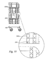
- Fig. 11 storage units 200, 200a of embodiments of the present inventive concept may have a first locking means 270 at a lower portion thereof.
- the first locking means 270 is provided as a short groove in a lateral wall structure portion 242a.
- first and second locking means 270, 272of two or more stacked storage units in tilted positions in each individual storage unit the second locking means 272 is displaced in the forward direction relative to the first locking means 270.
- first locking means of one storage unit will not mate with the second locking means of an underlying storage unit.
- first and second locking means when tilted ( Figs. 4-5 ), the first and second locking means will (if geometrically projected down to the trolley) for each storage unit be located at approximately the same position between the forward and rearward edges of the trolley.
- the storage unit may have several first locking means and several second locking means, e.g. one first and second locking means on each lateral wall structure or side of the storage unit.
- first and second locking means e.g. one first and second locking means on each lateral wall structure or side of the storage unit.
- the number of first and second locking means is four each, two located forwardly and two rearwardly.
- separating plates 274 may be provided in the storage units for placing items in defined spaces.
- loaves of bread may arranged upright, next to each other, separated by said separating plates 274, which may suitably be removable and/or re-arrangable in different positions.
- the brackets or crossbars (blocking means 248) are shown in a blocking position in Fig. 5 , reducing the risk of items, such as loaves of bread, falling out. This may be suitable during transportation of the system.
- the crossbars may be arranged in a non-blocking position, e.g. lowered to the forward edge of the storage unit at the bottom wall structure.
- the posts 284 at the upper half of the lateral wall structure of a first storage unit is adapted to be guided into the vertical track 280 at the lower half of the lateral wall structure of a second storage unit, when the second storage unit is mounted on top of the first storage unit in the non-tilted position shown in Figs. 6-8 .
- Fig. 12 illustrates the possibility of connecting two trolleys 100, 100a to each other, in accordance with at least one exemplary embodiment of the present inventive concept.
- the trolleys 100, 100a may be connected in any suitably way.
- the trolley in Fig. 1 illustrates a hole 190 or blind hole in the rearward portion 122 of the base and a similar hole 192 or blind hole in the forward portion 120.
- a connecting arm 294 which may be provided with pegs or bolts at its respective ends for engaging holes 290, 292 may be used for connecting the two trolleys 100, 100a.
Priority Applications (1)
| Application Number | Priority Date | Filing Date | Title |
|---|---|---|---|
| EP14175943.1A EP2965968A1 (fr) | 2014-07-07 | 2014-07-07 | Chariot, unité de stockage et chariot et système d'unité de stockage |
Applications Claiming Priority (1)
| Application Number | Priority Date | Filing Date | Title |
|---|---|---|---|
| EP14175943.1A EP2965968A1 (fr) | 2014-07-07 | 2014-07-07 | Chariot, unité de stockage et chariot et système d'unité de stockage |
Publications (1)
| Publication Number | Publication Date |
|---|---|
| EP2965968A1 true EP2965968A1 (fr) | 2016-01-13 |
Family
ID=51178708
Family Applications (1)
| Application Number | Title | Priority Date | Filing Date |
|---|---|---|---|
| EP14175943.1A Withdrawn EP2965968A1 (fr) | 2014-07-07 | 2014-07-07 | Chariot, unité de stockage et chariot et système d'unité de stockage |
Country Status (1)
| Country | Link |
|---|---|
| EP (1) | EP2965968A1 (fr) |
Citations (4)
| Publication number | Priority date | Publication date | Assignee | Title |
|---|---|---|---|---|
| US2916293A (en) * | 1958-05-14 | 1959-12-08 | United Steel & Wire Co | Combined transporting and display apparatus |
| AU2004235588A1 (en) * | 2003-12-02 | 2005-06-16 | Displayco | Stackable trolley |
| WO2005112710A1 (fr) * | 2004-05-21 | 2005-12-01 | Checkmate International Pty Ltd | Caisses, plateaux et boites de presentation |
| WO2007028194A1 (fr) * | 2005-09-05 | 2007-03-15 | Checkmate International Pty Ltd | Appareil pour transporter des produits dans des caisses ou contenants |
-
2014
- 2014-07-07 EP EP14175943.1A patent/EP2965968A1/fr not_active Withdrawn
Patent Citations (4)
| Publication number | Priority date | Publication date | Assignee | Title |
|---|---|---|---|---|
| US2916293A (en) * | 1958-05-14 | 1959-12-08 | United Steel & Wire Co | Combined transporting and display apparatus |
| AU2004235588A1 (en) * | 2003-12-02 | 2005-06-16 | Displayco | Stackable trolley |
| WO2005112710A1 (fr) * | 2004-05-21 | 2005-12-01 | Checkmate International Pty Ltd | Caisses, plateaux et boites de presentation |
| WO2007028194A1 (fr) * | 2005-09-05 | 2007-03-15 | Checkmate International Pty Ltd | Appareil pour transporter des produits dans des caisses ou contenants |
Similar Documents
| Publication | Publication Date | Title |
|---|---|---|
| US4441615A (en) | Stackable tray | |
| CA2712918C (fr) | Plateau et chariot a boulangerie | |
| US5896992A (en) | Nestable bakery tray | |
| US4520928A (en) | Nestable/stackable containers for bakery goods and the like | |
| CA2389010C (fr) | Plateau polyvalent | |
| CA2408247C (fr) | Plateau a emboitement et empilage sur plusieurs niveaux | |
| US6394274B1 (en) | Stackable bakery tray | |
| US6105980A (en) | Box for use with a dolly as a box and dolly system | |
| EP1931552B1 (fr) | Appareil pour transporter des produits dans des caisses ou contenants | |
| EP2688808B1 (fr) | Plateau à trois étages | |
| US20070175790A1 (en) | Stackable tray | |
| US5605102A (en) | Hand cart platform | |
| US4570798A (en) | Stackable container for use in bakery goods distribution systems, and the like | |
| HUE033507T2 (en) | Delivery and presentation box | |
| US4308954A (en) | Plastic nestable-stackable receptacle | |
| US3887207A (en) | Cart | |
| EP2426059B1 (fr) | Récipient emboîtable et gerbable | |
| EP2965968A1 (fr) | Chariot, unité de stockage et chariot et système d'unité de stockage | |
| AU2014202568B2 (en) | Transport and presentation box | |
| AU2021101162A4 (en) | Anti-tip trolley | |
| AU2006289649B2 (en) | Apparatus for transporting products in crates or containers | |
| GB2148851A (en) | Containers for bakery goods and the like | |
| CA2459700A1 (fr) | Dispositif de transport de produits de boulangerie et de patisseries | |
| NZ729171A (en) | Lift and Pallet | |
| EP1129645A1 (fr) | Casier de stockage |
Legal Events
| Date | Code | Title | Description |
|---|---|---|---|
| PUAI | Public reference made under article 153(3) epc to a published international application that has entered the european phase |
Free format text: ORIGINAL CODE: 0009012 |
|
| AK | Designated contracting states |
Kind code of ref document: A1 Designated state(s): AL AT BE BG CH CY CZ DE DK EE ES FI FR GB GR HR HU IE IS IT LI LT LU LV MC MK MT NL NO PL PT RO RS SE SI SK SM TR |
|
| AX | Request for extension of the european patent |
Extension state: BA ME |
|
| STAA | Information on the status of an ep patent application or granted ep patent |
Free format text: STATUS: THE APPLICATION IS DEEMED TO BE WITHDRAWN |
|
| 18D | Application deemed to be withdrawn |
Effective date: 20160714 |