EP2965855A2 - Herstellungsverfahren eines reliefmotivs aus einem material vom typ polymer auf einem substrat - Google Patents
Herstellungsverfahren eines reliefmotivs aus einem material vom typ polymer auf einem substrat Download PDFInfo
- Publication number
- EP2965855A2 EP2965855A2 EP15172623.9A EP15172623A EP2965855A2 EP 2965855 A2 EP2965855 A2 EP 2965855A2 EP 15172623 A EP15172623 A EP 15172623A EP 2965855 A2 EP2965855 A2 EP 2965855A2
- Authority
- EP
- European Patent Office
- Prior art keywords
- substrate
- sacrificial layer
- pattern
- free surface
- cavities
- Prior art date
- Legal status (The legal status is an assumption and is not a legal conclusion. Google has not performed a legal analysis and makes no representation as to the accuracy of the status listed.)
- Granted
Links
Images


Classifications
-
- B—PERFORMING OPERATIONS; TRANSPORTING
- B29—WORKING OF PLASTICS; WORKING OF SUBSTANCES IN A PLASTIC STATE IN GENERAL
- B29C—SHAPING OR JOINING OF PLASTICS; SHAPING OF MATERIAL IN A PLASTIC STATE, NOT OTHERWISE PROVIDED FOR; AFTER-TREATMENT OF THE SHAPED PRODUCTS, e.g. REPAIRING
- B29C39/00—Shaping by casting, i.e. introducing the moulding material into a mould or between confining surfaces without significant moulding pressure; Apparatus therefor
- B29C39/02—Shaping by casting, i.e. introducing the moulding material into a mould or between confining surfaces without significant moulding pressure; Apparatus therefor for making articles of definite length, i.e. discrete articles
- B29C39/10—Shaping by casting, i.e. introducing the moulding material into a mould or between confining surfaces without significant moulding pressure; Apparatus therefor for making articles of definite length, i.e. discrete articles incorporating preformed parts or layers, e.g. casting around inserts or for coating articles
-
- B—PERFORMING OPERATIONS; TRANSPORTING
- B23—MACHINE TOOLS; METAL-WORKING NOT OTHERWISE PROVIDED FOR
- B23K—SOLDERING OR UNSOLDERING; WELDING; CLADDING OR PLATING BY SOLDERING OR WELDING; CUTTING BY APPLYING HEAT LOCALLY, e.g. FLAME CUTTING; WORKING BY LASER BEAM
- B23K26/00—Working by laser beam, e.g. welding, cutting or boring
- B23K26/36—Removing material
- B23K26/362—Laser etching
- B23K26/364—Laser etching for making a groove or trench, e.g. for scribing a break initiation groove
-
- B—PERFORMING OPERATIONS; TRANSPORTING
- B23—MACHINE TOOLS; METAL-WORKING NOT OTHERWISE PROVIDED FOR
- B23K—SOLDERING OR UNSOLDERING; WELDING; CLADDING OR PLATING BY SOLDERING OR WELDING; CUTTING BY APPLYING HEAT LOCALLY, e.g. FLAME CUTTING; WORKING BY LASER BEAM
- B23K26/00—Working by laser beam, e.g. welding, cutting or boring
- B23K26/18—Working by laser beam, e.g. welding, cutting or boring using absorbing layers on the workpiece, e.g. for marking or protecting purposes
-
- B—PERFORMING OPERATIONS; TRANSPORTING
- B44—DECORATIVE ARTS
- B44D—PAINTING OR ARTISTIC DRAWING, NOT OTHERWISE PROVIDED FOR; PRESERVING PAINTINGS; SURFACE TREATMENT TO OBTAIN SPECIAL ARTISTIC SURFACE EFFECTS OR FINISHES
- B44D5/00—Surface treatment to obtain special artistic surface effects or finishes
-
- G—PHYSICS
- G04—HOROLOGY
- G04B—MECHANICALLY-DRIVEN CLOCKS OR WATCHES; MECHANICAL PARTS OF CLOCKS OR WATCHES IN GENERAL; TIME PIECES USING THE POSITION OF THE SUN, MOON OR STARS
- G04B19/00—Indicating the time by visual means
- G04B19/06—Dials
- G04B19/12—Selection of materials for dials or graduations markings
-
- G—PHYSICS
- G04—HOROLOGY
- G04B—MECHANICALLY-DRIVEN CLOCKS OR WATCHES; MECHANICAL PARTS OF CLOCKS OR WATCHES IN GENERAL; TIME PIECES USING THE POSITION OF THE SUN, MOON OR STARS
- G04B37/00—Cases
- G04B37/22—Materials or processes of manufacturing pocket watch or wrist watch cases
-
- A—HUMAN NECESSITIES
- A44—HABERDASHERY; JEWELLERY
- A44C—PERSONAL ADORNMENTS, e.g. JEWELLERY; COINS
- A44C27/00—Making jewellery or other personal adornments
- A44C27/001—Materials for manufacturing jewellery
- A44C27/005—Coating layers for jewellery
- A44C27/007—Non-metallic coatings
-
- B—PERFORMING OPERATIONS; TRANSPORTING
- B23—MACHINE TOOLS; METAL-WORKING NOT OTHERWISE PROVIDED FOR
- B23K—SOLDERING OR UNSOLDERING; WELDING; CLADDING OR PLATING BY SOLDERING OR WELDING; CUTTING BY APPLYING HEAT LOCALLY, e.g. FLAME CUTTING; WORKING BY LASER BEAM
- B23K2101/00—Articles made by soldering, welding or cutting
- B23K2101/36—Electric or electronic devices
- B23K2101/40—Semiconductor devices
-
- B—PERFORMING OPERATIONS; TRANSPORTING
- B23—MACHINE TOOLS; METAL-WORKING NOT OTHERWISE PROVIDED FOR
- B23K—SOLDERING OR UNSOLDERING; WELDING; CLADDING OR PLATING BY SOLDERING OR WELDING; CUTTING BY APPLYING HEAT LOCALLY, e.g. FLAME CUTTING; WORKING BY LASER BEAM
- B23K2103/00—Materials to be soldered, welded or cut
- B23K2103/30—Organic material
- B23K2103/42—Plastics
-
- B—PERFORMING OPERATIONS; TRANSPORTING
- B23—MACHINE TOOLS; METAL-WORKING NOT OTHERWISE PROVIDED FOR
- B23K—SOLDERING OR UNSOLDERING; WELDING; CLADDING OR PLATING BY SOLDERING OR WELDING; CUTTING BY APPLYING HEAT LOCALLY, e.g. FLAME CUTTING; WORKING BY LASER BEAM
- B23K2103/00—Materials to be soldered, welded or cut
- B23K2103/50—Inorganic material, e.g. metals, not provided for in B23K2103/02 – B23K2103/26
-
- B—PERFORMING OPERATIONS; TRANSPORTING
- B29—WORKING OF PLASTICS; WORKING OF SUBSTANCES IN A PLASTIC STATE IN GENERAL
- B29L—INDEXING SCHEME ASSOCIATED WITH SUBCLASS B29C, RELATING TO PARTICULAR ARTICLES
- B29L2031/00—Other particular articles
- B29L2031/722—Decorative or ornamental articles
-
- G—PHYSICS
- G04—HOROLOGY
- G04B—MECHANICALLY-DRIVEN CLOCKS OR WATCHES; MECHANICAL PARTS OF CLOCKS OR WATCHES IN GENERAL; TIME PIECES USING THE POSITION OF THE SUN, MOON OR STARS
- G04B45/00—Time pieces of which the indicating means or cases provoke special effects, e.g. aesthetic effects
- G04B45/0076—Decoration of the case and of parts thereof, e.g. as a method of manufacture thereof
-
- G—PHYSICS
- G04—HOROLOGY
- G04D—APPARATUS OR TOOLS SPECIALLY DESIGNED FOR MAKING OR MAINTAINING CLOCKS OR WATCHES
- G04D3/00—Watchmakers' or watch-repairers' machines or tools for working materials
- G04D3/0074—Watchmakers' or watch-repairers' machines or tools for working materials for treatment of the material, e.g. surface treatment
Definitions
- the present invention relates to a method of producing a relief pattern, of a polymer type material, on a substrate.
- the method according to the invention may notably allow the realization of such a pattern in relief on a substrate defined by a component that may be used in the production of a watch.
- the present method can be implemented on a surface of the substrate which would have been previously finished without altering its finish.
- the method according to the invention can be used to affix the sign of a trademark, and / or a corresponding logo, on at least one component of a finished product marketed under this trademark.
- the material used for producing the relief pattern is advantageously taken from the group comprising elastomers, epoxy resins and polyurethane lacquers.
- the substrate may be of any kind allowing the application of a material of the type just mentioned, in particular metal or metal alloy, or ceramic.
- the EP 2316299 B1 discloses a method of applying an elastomer to a substrate having at least one relief, such that the final surface of the elastomeric layer is arranged in continuity with the relief surface.
- This document further provides that the same surface treatment is finally applied to the entire surface, such as, for example, polishing or satin finish, to obtain similar surface conditions on the relief and on the surface of the elastomer.
- the deposition of such materials on a substrate is carried out inside recesses formed in the surface of the substrate, particularly with the idea that such an approach makes it possible to improve the anchoring of these materials on the substrate. and to prevent them from being easily torn off.
- An object of the present invention is to provide an alternative to the methods known from the prior art by proposing a method for producing a pattern in relief on a continuous surface, possibly finished, of a substrate, that is to say also on the surface of a substrate that does not have a cavity.
- a relief pattern can be made on any type of surface, in particular on a continuous surface, that is to say a surface having no cavity delimited by at least one edge.
- an embossed pattern according to the present invention may advantageously be made on a clear surface, possibly substantially flat. Indeed, the Applicant has found that the relief patterns obtained by the implementation of this method have a satisfactory resistance to tearing, against all odds, even though they do not have a portion housed in a cavity that would have been previously formed in the surface of the substrate.
- a raised pattern produced by the implementation of the method according to the invention has a predefined volume delimited by at least two surfaces of which one is substantially continuous and provides the mechanical connection of the relief pattern to the continuous free surface of the substrate, and the other or the others are advantageously free of any interaction with the substrate.
- the pattern can have any type of shape and any desired thickness.
- the thickness of the relief pattern obtained may be less than 2 mm, preferably less than 1 mm, even more preferably substantially between 0.1 and 0.2 mm.
- relief patterns according to the present invention is possible on a free surface of the substrate which would be previously finished, without altering the finish. Indeed, the free surface is protected by the first sacrificial layer during the deposition of the polymer-type material and, especially, during the step of ablation of the surplus of this material.
- the surface of the deposited material can be subjected to any desired finish, while the free surface of the substrate is always protected by at least one of the sacrificial layers, which allows for different surface finishes, on the relief pattern and, on the other hand, on the substrate.
- the first sacrificial layer must be rigid enough to allow a precise definition of the cavities to be filled which will allow the formation of the relief pattern. It can be made of any suitable material such as a metal compound or an epoxy resin for example.
- a second sacrificial layer is deposited on the first sacrificial layer prior to defining the cavities to be filled.
- the first and second sacrificial layers are then etched in one or more steps during the implementation of step c).
- the second sacrificial layer is then preferably removed prior to the ablation of the first sacrificial layer during the implementation of step f).
- the second sacrificial layer is for example a photosensitive resin, removed by etching, for example, the first sacrificial layer can then advantageously be of metal type.
- the free surface of the substrate has a mechanical finish taken from the group comprising satin, brushing, polishing and sanding.
- the selective ablation of the first sacrificial layer in step f) is performed by laser treatment.
- the method comprises a further step of performing a finishing surface treatment on the relief pattern.
- a finishing surface treatment can be applied to the surface of the relief pattern without risk of causing damage to the surface. free surface of the substrate.
- finishing surface treatment on the relief pattern is performed in conjunction with the implementation of step e) or step f).
- the surface of the relief pattern can be finished with the type of finish desired directly at the end of ablation surplus, which represents a significant time saving.
- the method just described can advantageously be used to carry out the production of a relief pattern on a watch component defining a substrate of metal, metal alloy or ceramic.
- the material used for producing the relief pattern is advantageously taken from the group comprising elastomers, epoxy resins and polyurethane lacquers.
- the present invention also relates to a watch component, comprising at least one portion defining a substrate having a continuous free surface, having a mechanical finish taken from the group consisting of satin, brushing, polishing and sanding, and bearing at least one embossed pattern made of a polymer type material and having the characteristics set out above.
- the embossed pattern has at least one free surface having a finish taken from the group comprising satinizing, brushing, sandblasting and micro-structuring by laser beam.
- FIG. 1 represents a partial schematic view of a substrate, in cross section, illustrating a first step of preparation for the implementation of a preferred embodiment of the method according to the invention
- the figure 2 represents a view similar to that of the figure 1 illustrating steps of implementation of a preferred embodiment of the method according to the invention
- FIG. 3 represents a view similar to that of the figure 1 illustrating an additional step of implementing a preferred embodiment of the method according to the invention
- FIG. 4 represents a view similar to that of the figure 1 , illustrating additional steps of implementation of a preferred embodiment of the method according to the invention
- FIG. 5 represents a view similar to that of the figure 1 illustrating an additional step of implementing a preferred embodiment of the method according to the invention
- FIG. 6 represents a view similar to that of the figure 1 illustrating an additional step of implementing a preferred embodiment of the method according to the invention
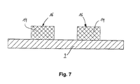
- FIG 7 represents a view similar to that of the figure 1 , illustrating an additional step of implementing a preferred embodiment of the method according to the invention.
- FIGS. 1 to 7 illustrate the step-by-step flow of an exemplary implementation of a method of producing a pattern in relief on a substrate, according to a preferred embodiment of the present invention.
- relief pattern it is appropriate to understand here any type of predefined form, including any figurative or non-figurative form, or even text.
- the method according to the invention can be used to affix the sign of a trademark, and / or a corresponding logo, on at least one component of a finished product marketed under this trademark.
- the concept of pattern also includes here a set of relief elements that would be disjointed from each other on the surface of a substrate.
- the figure 1 illustrates a first step prior to the method according to the present invention consisting in providing a substrate 1 which may in particular be composed at least partially of a metal, a metal alloy or a ceramic.
- a substrate 1 which may in particular be composed at least partially of a metal, a metal alloy or a ceramic.
- a substrate 1 which may in particular be composed at least partially of a metal, a metal alloy or a ceramic.
- the substrate 1 comprises a free surface 2 which can be rough or have any type of finish, such as a mechanical finish such as satin, brushing, polishing or sandblasting.
- the free surface 2 may also have various types of geometries without departing from the scope of the invention. As mentioned above, the free surface 2 may in particular be continuous, that is to say that it may not have a cavity that would have been formed prior to the implementation of the method according to the invention. The free surface 2 may in particular be substantially flat, as illustrated in the figures.
- the figure 2 illustrates first steps of implementation of the method according to the present invention of depositing first and second sacrificial layers 4 and 6 on the free surface 2 of the substrate 1.
- the first sacrificial layer 4 is metallic, for example silver or copper, and may be deposited by the implementation of any suitable known method, such as a galvanic deposition. It can preferably be deposited with a thickness of up to 2 mm, preferably less than 1 mm, even more preferably between 0.1 and 0.2 mm.
- the second sacrificial layer 6 consists of a conventional photosensitive resin and can be deposited by any known and adapted method. Typically, the second sacrificial layer 6 may have a thickness of less than 1 mm, preferably less than 0.5 mm, even more preferably less than 0.1 mm.
- the establishment of the second sacrificial layer 6 can be omitted without departing from the scope of the present invention.
- the figure 3 illustrates a further step of the method according to the present invention, optional in the case of an implementation with a single sacrificial layer, during which the second sacrificial layer 6 is etched selectively, to make accessible portions 8 of the first sacrificial layer 4 corresponding to the pattern to be produced.
- Any known and adapted method can be implemented here without departing from the scope of the present invention, such as, for example, a method of etching the second sacrificial layer 6 by etching, after having covered it with a mask making it possible to protect the regions that do not match the pattern to be made and have activated by light irradiation.
- the method according to the invention comprises the implementation of an additional step, the result of which is illustrated on the figure 4 , consisting in eliminating the first sacrificial layer 4 in its regions which have been exposed to the preceding step, that is to say at its accessible portions 8.
- the first sacrificial layer 4 is thus etched or hollowed out, selectively, preferably to the free surface 2 of the substrate 1 to define cavities 10 to be filled with the material used to make the relief pattern.
- This operation is preferably performed by selective irradiation of the first sacrificial layer 4 by means of a conventional laser beam, but can be achieved by other methods without departing from the scope of the present invention.
- a bonding agent or "primer” shown schematically by the dotted lines referenced 12
- the skilled person will not encounter any particular difficulty in making the choice of the bonding agent 12, according to his own needs and without departing from the scope of this invention.
- the preferred typical thickness for the layer of the bonding agent is of the order of 5 to 10 .mu.m, by way of nonlimiting illustration.
- a preparation surface treatment prior to, or alternatively, depositing the bonding agent 12, such as sandblasting or etching.
- the material 14 used to make the relief pattern can then be deposited on the substrate 1, as illustrated in FIG. figure 5 .
- This material 14 is preferably selected from the group consisting of elastomers, epoxy resins and polyurethane lacquers.
- the application of the material 14 is carried out conventionally, for example by overmolding.
- the material 14 is deposited on the substrate 1 so that at least the cavities 10 are filled.
- the deposit gives rise to a surplus of material 14 located above the second sacrificial layer 6, as shown schematically in FIG. figure 5 .
- a typical order of magnitude for the thickness of the material layer 14 located above the second sacrificial layer 6 is 0.05 to 0.2 mm, but not limited to.
- a polymerization and / or vulcanization operation is preferably provided after deposition of the material 14.
- An additional step of the method according to the present invention consists in eliminating the surplus of material 14 situated outside the cavities 10. The result of the corresponding ablation is illustrated in FIG. figure 6 .
- the ablation operation may be performed in several steps, by the implementation of one or more conventional methods, such as for example a mechanical machining (grinding, grinding, etc.), a chemical attack or a heat treatment, in particular by laser beam.
- a mechanical machining grinding, grinding, etc.
- a chemical attack or a heat treatment, in particular by laser beam.
- the ablation can be performed in a single step, by means of a laser beam.
- the final surface 16 of the material 14 is microstructured. It is thus possible to make any type of pattern on the final surface 16 of the material 14, such as for example Paris nails or a corporate logo or brand.
- the removal of the surplus of filling material 14 by a laser beam makes it possible to achieve a great deal of precision in carrying out the ablation, even when the level of the final surface 16 is situated lower than the level of the second sacrificial layer. 6.
- finishing treatment by laser beam
- a finishing surface treatment on the final surface 16 of the material 14 after removal of the surplus, such as, for example, sanding.
- the first and second sacrificial layers 4 and 6 being always present, the free surface 2 of the substrate 1 is protected and can not be damaged by such finishing treatment.
- the first and second sacrificial layers 4 and 6 can be selectively removed, i.e. without removing the material 14, as illustrated in FIG. figure 7 .
- These operations are preferably carried out in a conventional manner, for example by etching for the removal of the second sacrificial layer 6, and by electrolysis for the first sacrificial layer 4.
- the free surface 2 of the substrate 1 is exposed, with the finish that it had before the implementation of the method according to the invention, except in the regions where the material 14 had been deposited in the cavities 10, giving instead of producing the desired relief pattern.
- the latter thus has a single surface ensuring its connection to the free surface of the substrate, its other surfaces being free of any interaction with the substrate.
- a first disc-shaped surface provides the connection of the relief pattern to the substrate, while the lateral cylindrical envelope and the second disc-shaped surface. are free of any interaction with the substrate.
- the process according to the invention can be used to affix the sign of a trademark and / or a corresponding logo on at least one component of a finished product marketed under this trademark.
- the method according to the invention can be implemented to apply patterns in relief on components or products marketed in the field of luxury, particularly in watchmaking, jewelery, telephony, etc ..., or to decorative purposes or identification of a mark, for example, for technical purposes, to perform functional markings (such as numbers and / or indexes on a watch bezel), for example, even mechanical when the elastic properties of the material 14 are exploited.
- the relief patterns according to the present invention can make it possible to catch up with a game (cogwheel, stop, hoop, seals, etc.), to absorb shocks (elements of the dressing of a watch or in the watch movement directly), to prevent friction between two components, or to play a role of thermal insulation, indicative non-limiting.
Applications Claiming Priority (1)
| Application Number | Priority Date | Filing Date | Title |
|---|---|---|---|
| CH00916/14A CH709789B1 (fr) | 2014-06-17 | 2014-06-17 | Composant comportant un motif en relief en matériau polymère |
Publications (3)
| Publication Number | Publication Date |
|---|---|
| EP2965855A2 true EP2965855A2 (de) | 2016-01-13 |
| EP2965855A3 EP2965855A3 (de) | 2016-03-09 |
| EP2965855B1 EP2965855B1 (de) | 2018-12-26 |
Family
ID=54207285
Family Applications (1)
| Application Number | Title | Priority Date | Filing Date |
|---|---|---|---|
| EP15172623.9A Active EP2965855B1 (de) | 2014-06-17 | 2015-06-17 | Herstellungsverfahren eines reliefmotivs aus einem material vom typ polymer auf einem substrat |
Country Status (2)
| Country | Link |
|---|---|
| EP (1) | EP2965855B1 (de) |
| CH (1) | CH709789B1 (de) |
Cited By (1)
| Publication number | Priority date | Publication date | Assignee | Title |
|---|---|---|---|---|
| EP3336614A1 (de) * | 2016-12-16 | 2018-06-20 | Rubattel et Weyermann S.A. | Verkleidungselement oder zifferblatt einer uhr aus nicht-leitendem material |
Citations (1)
| Publication number | Priority date | Publication date | Assignee | Title |
|---|---|---|---|---|
| EP2316299B1 (de) | 2009-10-27 | 2013-02-27 | Biwi S.A. | Teil, das eine Struktur aus anorganischem Material und eine Elastomerschicht umfasst, und Verfahren zur Herstellung eines solchen Teils |
Family Cites Families (1)
| Publication number | Priority date | Publication date | Assignee | Title |
|---|---|---|---|---|
| CH702731A1 (fr) * | 2010-02-25 | 2011-08-31 | Biwi Sa | Procédé de fabrication d'une pièce comportant un revêtement élastomère et ladite pièce obtenue. |
-
2014
- 2014-06-17 CH CH00916/14A patent/CH709789B1/fr unknown
-
2015
- 2015-06-17 EP EP15172623.9A patent/EP2965855B1/de active Active
Patent Citations (1)
| Publication number | Priority date | Publication date | Assignee | Title |
|---|---|---|---|---|
| EP2316299B1 (de) | 2009-10-27 | 2013-02-27 | Biwi S.A. | Teil, das eine Struktur aus anorganischem Material und eine Elastomerschicht umfasst, und Verfahren zur Herstellung eines solchen Teils |
Cited By (6)
| Publication number | Priority date | Publication date | Assignee | Title |
|---|---|---|---|---|
| EP3336614A1 (de) * | 2016-12-16 | 2018-06-20 | Rubattel et Weyermann S.A. | Verkleidungselement oder zifferblatt einer uhr aus nicht-leitendem material |
| WO2018109065A1 (fr) * | 2016-12-16 | 2018-06-21 | Rubattel Et Weyermann S.A. | Element d'habillage ou cadran d'horlogerie en materiau non conducteur |
| CN110268337A (zh) * | 2016-12-16 | 2019-09-20 | 鲁巴特和韦尔曼股份有限公司 | 由非导电材料制成的钟表表盘或外部元件 |
| JP2020501148A (ja) * | 2016-12-16 | 2020-01-16 | ルバテル・エ・ワイエルマン・エス アー | 非導電素材からなる外部要素または計時器文字盤 |
| CN110268337B (zh) * | 2016-12-16 | 2021-08-03 | 鲁巴特和韦尔曼股份有限公司 | 由非导电材料制成的钟表表盘或外部元件 |
| US11577544B2 (en) | 2016-12-16 | 2023-02-14 | Rubattel & Weyermann S.A. | External element or timepiece dial made of non-conductive material |
Also Published As
| Publication number | Publication date |
|---|---|
| CH709789A2 (fr) | 2015-12-31 |
| EP2965855B1 (de) | 2018-12-26 |
| CH709789B1 (fr) | 2021-05-31 |
| EP2965855A3 (de) | 2016-03-09 |
Similar Documents
| Publication | Publication Date | Title |
|---|---|---|
| EP2380864B1 (de) | Verfahren zur Herstellung eines Keramikelements mit mindestens einem Metalldekoreinsatz | |
| EP3555709B1 (de) | Verkleidungselement oder zifferblatt einer uhr aus nicht-leitendem material | |
| EP3126914B1 (de) | Verfahren zur herstellung einer uhrenkomponente mit einem einsatz aus einem verbundmaterial und zugehörige uhrenkomponente und uhr | |
| CH713871B1 (fr) | Composant horloger comprenant des éléments graphiques de divers aspects et procédé de fabrication d'un tel composant. | |
| EP2316299B1 (de) | Teil, das eine Struktur aus anorganischem Material und eine Elastomerschicht umfasst, und Verfahren zur Herstellung eines solchen Teils | |
| EP2902177B1 (de) | Verfahren zur Aufbringung eines Füllmaterials auf ein Substrat, das eine freie Oberfläche in fertigem Zustand darstellt | |
| EP2965855B1 (de) | Herstellungsverfahren eines reliefmotivs aus einem material vom typ polymer auf einem substrat | |
| EP2840059B1 (de) | Verfahren zur Herstellung eines mikromechanischen Teils und Teil hergestellt durch dieses Verfahren | |
| EP3786722A1 (de) | Verfahren zur dekoration eines mechanischen bauteils | |
| EP3839626A1 (de) | Verfahren zur herstellung einer uhrkomponente und nach diesem verfahren hergestellte komponente | |
| CH712475A2 (fr) | Procédé de fabrication d'une pièce pour l'horlogerie dotée d'un élément d'habillage creux ou en relief. | |
| EP2881808B1 (de) | Verfahren zur Herstellung einer Uhrkomponente | |
| CH712474A2 (fr) | Procédé de fabrication d'une pièce pour l'horlogerie dotée d'un élément d'habillage en relief. | |
| EP3839659B1 (de) | Verfahren zur dekoration eines mechanischen bauteils | |
| EP3412625A1 (de) | Herstellungsverfahren eines mikromechanischen bauteils | |
| EP2796065B1 (de) | Unsichtbares eingepresstes Dekorteil | |
| EP3587626B1 (de) | Dekorteil, das durch inlayarbeiten erstellt wird | |
| EP4338639A1 (de) | Verfahren zur herstellung einer verkleidungskomponente mit einem beugungsgitter | |
| CH713854A2 (fr) | Procédé de fabrication d'une pièce micromécanique. | |
| CH715954B1 (fr) | Procédé de décoration d'une pièce mécanique. | |
| CH716363B1 (fr) | Procédé de décoration d'une pièce mécanique. | |
| EP1930792A2 (de) | Organ für eine Uhr | |
| EP2837976A2 (de) | Verfahren zur Herstellung eines mechanischen Bauteils |
Legal Events
| Date | Code | Title | Description |
|---|---|---|---|
| PUAI | Public reference made under article 153(3) epc to a published international application that has entered the european phase |
Free format text: ORIGINAL CODE: 0009012 |
|
| AK | Designated contracting states |
Kind code of ref document: A2 Designated state(s): AL AT BE BG CH CY CZ DE DK EE ES FI FR GB GR HR HU IE IS IT LI LT LU LV MC MK MT NL NO PL PT RO RS SE SI SK SM TR |
|
| AX | Request for extension of the european patent |
Extension state: BA ME |
|
| PUAL | Search report despatched |
Free format text: ORIGINAL CODE: 0009013 |
|
| AK | Designated contracting states |
Kind code of ref document: A3 Designated state(s): AL AT BE BG CH CY CZ DE DK EE ES FI FR GB GR HR HU IE IS IT LI LT LU LV MC MK MT NL NO PL PT RO RS SE SI SK SM TR |
|
| AX | Request for extension of the european patent |
Extension state: BA ME |
|
| RIC1 | Information provided on ipc code assigned before grant |
Ipc: B23K 26/362 20140101AFI20160202BHEP Ipc: G04B 47/04 20060101ALI20160202BHEP Ipc: B23K 26/402 20140101ALI20160202BHEP Ipc: B29C 69/00 20060101ALI20160202BHEP |
|
| 17P | Request for examination filed |
Effective date: 20160909 |
|
| RBV | Designated contracting states (corrected) |
Designated state(s): AL AT BE BG CH CY CZ DE DK EE ES FI FR GB GR HR HU IE IS IT LI LT LU LV MC MK MT NL NO PL PT RO RS SE SI SK SM TR |
|
| STAA | Information on the status of an ep patent application or granted ep patent |
Free format text: STATUS: REQUEST FOR EXAMINATION WAS MADE |
|
| R17P | Request for examination filed (corrected) |
Effective date: 20160909 |
|
| STAA | Information on the status of an ep patent application or granted ep patent |
Free format text: STATUS: EXAMINATION IS IN PROGRESS |
|
| 17Q | First examination report despatched |
Effective date: 20180223 |
|
| GRAP | Despatch of communication of intention to grant a patent |
Free format text: ORIGINAL CODE: EPIDOSNIGR1 |
|
| STAA | Information on the status of an ep patent application or granted ep patent |
Free format text: STATUS: GRANT OF PATENT IS INTENDED |
|
| INTG | Intention to grant announced |
Effective date: 20180730 |
|
| GRAS | Grant fee paid |
Free format text: ORIGINAL CODE: EPIDOSNIGR3 |
|
| GRAA | (expected) grant |
Free format text: ORIGINAL CODE: 0009210 |
|
| STAA | Information on the status of an ep patent application or granted ep patent |
Free format text: STATUS: THE PATENT HAS BEEN GRANTED |
|
| AK | Designated contracting states |
Kind code of ref document: B1 Designated state(s): AL AT BE BG CH CY CZ DE DK EE ES FI FR GB GR HR HU IE IS IT LI LT LU LV MC MK MT NL NO PL PT RO RS SE SI SK SM TR |
|
| REG | Reference to a national code |
Ref country code: GB Ref legal event code: FG4D Free format text: NOT ENGLISH |
|
| REG | Reference to a national code |
Ref country code: CH Ref legal event code: EP |
|
| REG | Reference to a national code |
Ref country code: AT Ref legal event code: REF Ref document number: 1080735 Country of ref document: AT Kind code of ref document: T Effective date: 20190115 |
|
| REG | Reference to a national code |
Ref country code: DE Ref legal event code: R096 Ref document number: 602015022135 Country of ref document: DE |
|
| REG | Reference to a national code |
Ref country code: IE Ref legal event code: FG4D Free format text: LANGUAGE OF EP DOCUMENT: FRENCH |
|
| PG25 | Lapsed in a contracting state [announced via postgrant information from national office to epo] |
Ref country code: HR Free format text: LAPSE BECAUSE OF FAILURE TO SUBMIT A TRANSLATION OF THE DESCRIPTION OR TO PAY THE FEE WITHIN THE PRESCRIBED TIME-LIMIT Effective date: 20181226 Ref country code: LV Free format text: LAPSE BECAUSE OF FAILURE TO SUBMIT A TRANSLATION OF THE DESCRIPTION OR TO PAY THE FEE WITHIN THE PRESCRIBED TIME-LIMIT Effective date: 20181226 Ref country code: FI Free format text: LAPSE BECAUSE OF FAILURE TO SUBMIT A TRANSLATION OF THE DESCRIPTION OR TO PAY THE FEE WITHIN THE PRESCRIBED TIME-LIMIT Effective date: 20181226 Ref country code: BG Free format text: LAPSE BECAUSE OF FAILURE TO SUBMIT A TRANSLATION OF THE DESCRIPTION OR TO PAY THE FEE WITHIN THE PRESCRIBED TIME-LIMIT Effective date: 20190326 Ref country code: LT Free format text: LAPSE BECAUSE OF FAILURE TO SUBMIT A TRANSLATION OF THE DESCRIPTION OR TO PAY THE FEE WITHIN THE PRESCRIBED TIME-LIMIT Effective date: 20181226 Ref country code: NO Free format text: LAPSE BECAUSE OF FAILURE TO SUBMIT A TRANSLATION OF THE DESCRIPTION OR TO PAY THE FEE WITHIN THE PRESCRIBED TIME-LIMIT Effective date: 20190326 |
|
| REG | Reference to a national code |
Ref country code: NL Ref legal event code: MP Effective date: 20181226 |
|
| REG | Reference to a national code |
Ref country code: LT Ref legal event code: MG4D |
|
| PG25 | Lapsed in a contracting state [announced via postgrant information from national office to epo] |
Ref country code: RS Free format text: LAPSE BECAUSE OF FAILURE TO SUBMIT A TRANSLATION OF THE DESCRIPTION OR TO PAY THE FEE WITHIN THE PRESCRIBED TIME-LIMIT Effective date: 20181226 Ref country code: GR Free format text: LAPSE BECAUSE OF FAILURE TO SUBMIT A TRANSLATION OF THE DESCRIPTION OR TO PAY THE FEE WITHIN THE PRESCRIBED TIME-LIMIT Effective date: 20190327 Ref country code: AL Free format text: LAPSE BECAUSE OF FAILURE TO SUBMIT A TRANSLATION OF THE DESCRIPTION OR TO PAY THE FEE WITHIN THE PRESCRIBED TIME-LIMIT Effective date: 20181226 Ref country code: SE Free format text: LAPSE BECAUSE OF FAILURE TO SUBMIT A TRANSLATION OF THE DESCRIPTION OR TO PAY THE FEE WITHIN THE PRESCRIBED TIME-LIMIT Effective date: 20181226 |
|
| REG | Reference to a national code |
Ref country code: CH Ref legal event code: NV Representative=s name: E-PATENT S.A., CH |
|
| REG | Reference to a national code |
Ref country code: AT Ref legal event code: MK05 Ref document number: 1080735 Country of ref document: AT Kind code of ref document: T Effective date: 20181226 |
|
| PG25 | Lapsed in a contracting state [announced via postgrant information from national office to epo] |
Ref country code: NL Free format text: LAPSE BECAUSE OF FAILURE TO SUBMIT A TRANSLATION OF THE DESCRIPTION OR TO PAY THE FEE WITHIN THE PRESCRIBED TIME-LIMIT Effective date: 20181226 |
|
| PG25 | Lapsed in a contracting state [announced via postgrant information from national office to epo] |
Ref country code: ES Free format text: LAPSE BECAUSE OF FAILURE TO SUBMIT A TRANSLATION OF THE DESCRIPTION OR TO PAY THE FEE WITHIN THE PRESCRIBED TIME-LIMIT Effective date: 20181226 Ref country code: PT Free format text: LAPSE BECAUSE OF FAILURE TO SUBMIT A TRANSLATION OF THE DESCRIPTION OR TO PAY THE FEE WITHIN THE PRESCRIBED TIME-LIMIT Effective date: 20190426 Ref country code: CZ Free format text: LAPSE BECAUSE OF FAILURE TO SUBMIT A TRANSLATION OF THE DESCRIPTION OR TO PAY THE FEE WITHIN THE PRESCRIBED TIME-LIMIT Effective date: 20181226 Ref country code: IT Free format text: LAPSE BECAUSE OF FAILURE TO SUBMIT A TRANSLATION OF THE DESCRIPTION OR TO PAY THE FEE WITHIN THE PRESCRIBED TIME-LIMIT Effective date: 20181226 Ref country code: PL Free format text: LAPSE BECAUSE OF FAILURE TO SUBMIT A TRANSLATION OF THE DESCRIPTION OR TO PAY THE FEE WITHIN THE PRESCRIBED TIME-LIMIT Effective date: 20181226 |
|
| PG25 | Lapsed in a contracting state [announced via postgrant information from national office to epo] |
Ref country code: SK Free format text: LAPSE BECAUSE OF FAILURE TO SUBMIT A TRANSLATION OF THE DESCRIPTION OR TO PAY THE FEE WITHIN THE PRESCRIBED TIME-LIMIT Effective date: 20181226 Ref country code: SM Free format text: LAPSE BECAUSE OF FAILURE TO SUBMIT A TRANSLATION OF THE DESCRIPTION OR TO PAY THE FEE WITHIN THE PRESCRIBED TIME-LIMIT Effective date: 20181226 Ref country code: EE Free format text: LAPSE BECAUSE OF FAILURE TO SUBMIT A TRANSLATION OF THE DESCRIPTION OR TO PAY THE FEE WITHIN THE PRESCRIBED TIME-LIMIT Effective date: 20181226 Ref country code: IS Free format text: LAPSE BECAUSE OF FAILURE TO SUBMIT A TRANSLATION OF THE DESCRIPTION OR TO PAY THE FEE WITHIN THE PRESCRIBED TIME-LIMIT Effective date: 20190426 Ref country code: RO Free format text: LAPSE BECAUSE OF FAILURE TO SUBMIT A TRANSLATION OF THE DESCRIPTION OR TO PAY THE FEE WITHIN THE PRESCRIBED TIME-LIMIT Effective date: 20181226 |
|
| REG | Reference to a national code |
Ref country code: DE Ref legal event code: R097 Ref document number: 602015022135 Country of ref document: DE |
|
| PG25 | Lapsed in a contracting state [announced via postgrant information from national office to epo] |
Ref country code: AT Free format text: LAPSE BECAUSE OF FAILURE TO SUBMIT A TRANSLATION OF THE DESCRIPTION OR TO PAY THE FEE WITHIN THE PRESCRIBED TIME-LIMIT Effective date: 20181226 Ref country code: DK Free format text: LAPSE BECAUSE OF FAILURE TO SUBMIT A TRANSLATION OF THE DESCRIPTION OR TO PAY THE FEE WITHIN THE PRESCRIBED TIME-LIMIT Effective date: 20181226 |
|
| PLBE | No opposition filed within time limit |
Free format text: ORIGINAL CODE: 0009261 |
|
| STAA | Information on the status of an ep patent application or granted ep patent |
Free format text: STATUS: NO OPPOSITION FILED WITHIN TIME LIMIT |
|
| 26N | No opposition filed |
Effective date: 20190927 |
|
| PG25 | Lapsed in a contracting state [announced via postgrant information from national office to epo] |
Ref country code: MC Free format text: LAPSE BECAUSE OF FAILURE TO SUBMIT A TRANSLATION OF THE DESCRIPTION OR TO PAY THE FEE WITHIN THE PRESCRIBED TIME-LIMIT Effective date: 20181226 |
|
| PG25 | Lapsed in a contracting state [announced via postgrant information from national office to epo] |
Ref country code: SI Free format text: LAPSE BECAUSE OF FAILURE TO SUBMIT A TRANSLATION OF THE DESCRIPTION OR TO PAY THE FEE WITHIN THE PRESCRIBED TIME-LIMIT Effective date: 20181226 |
|
| REG | Reference to a national code |
Ref country code: BE Ref legal event code: MM Effective date: 20190630 |
|
| PG25 | Lapsed in a contracting state [announced via postgrant information from national office to epo] |
Ref country code: TR Free format text: LAPSE BECAUSE OF FAILURE TO SUBMIT A TRANSLATION OF THE DESCRIPTION OR TO PAY THE FEE WITHIN THE PRESCRIBED TIME-LIMIT Effective date: 20181226 |
|
| PG25 | Lapsed in a contracting state [announced via postgrant information from national office to epo] |
Ref country code: IE Free format text: LAPSE BECAUSE OF NON-PAYMENT OF DUE FEES Effective date: 20190617 |
|
| PG25 | Lapsed in a contracting state [announced via postgrant information from national office to epo] |
Ref country code: LU Free format text: LAPSE BECAUSE OF NON-PAYMENT OF DUE FEES Effective date: 20190617 Ref country code: BE Free format text: LAPSE BECAUSE OF NON-PAYMENT OF DUE FEES Effective date: 20190630 |
|
| PG25 | Lapsed in a contracting state [announced via postgrant information from national office to epo] |
Ref country code: CY Free format text: LAPSE BECAUSE OF FAILURE TO SUBMIT A TRANSLATION OF THE DESCRIPTION OR TO PAY THE FEE WITHIN THE PRESCRIBED TIME-LIMIT Effective date: 20181226 |
|
| PG25 | Lapsed in a contracting state [announced via postgrant information from national office to epo] |
Ref country code: MT Free format text: LAPSE BECAUSE OF FAILURE TO SUBMIT A TRANSLATION OF THE DESCRIPTION OR TO PAY THE FEE WITHIN THE PRESCRIBED TIME-LIMIT Effective date: 20181226 Ref country code: HU Free format text: LAPSE BECAUSE OF FAILURE TO SUBMIT A TRANSLATION OF THE DESCRIPTION OR TO PAY THE FEE WITHIN THE PRESCRIBED TIME-LIMIT; INVALID AB INITIO Effective date: 20150617 |
|
| PG25 | Lapsed in a contracting state [announced via postgrant information from national office to epo] |
Ref country code: MK Free format text: LAPSE BECAUSE OF FAILURE TO SUBMIT A TRANSLATION OF THE DESCRIPTION OR TO PAY THE FEE WITHIN THE PRESCRIBED TIME-LIMIT Effective date: 20181226 |
|
| PGFP | Annual fee paid to national office [announced via postgrant information from national office to epo] |
Ref country code: FR Payment date: 20230626 Year of fee payment: 9 Ref country code: DE Payment date: 20230626 Year of fee payment: 9 |
|
| PGFP | Annual fee paid to national office [announced via postgrant information from national office to epo] |
Ref country code: GB Payment date: 20230627 Year of fee payment: 9 Ref country code: CH Payment date: 20230702 Year of fee payment: 9 |