EP2965700A1 - Instrument fixation device for depth and angle fixation - Google Patents
Instrument fixation device for depth and angle fixation Download PDFInfo
- Publication number
- EP2965700A1 EP2965700A1 EP15175746.5A EP15175746A EP2965700A1 EP 2965700 A1 EP2965700 A1 EP 2965700A1 EP 15175746 A EP15175746 A EP 15175746A EP 2965700 A1 EP2965700 A1 EP 2965700A1
- Authority
- EP
- European Patent Office
- Prior art keywords
- ball joint
- instrument
- retaining ring
- channel
- surgical
- Prior art date
- Legal status (The legal status is an assumption and is not a legal conclusion. Google has not performed a legal analysis and makes no representation as to the accuracy of the status listed.)
- Granted
Links
Images




Classifications
-
- A—HUMAN NECESSITIES
- A61—MEDICAL OR VETERINARY SCIENCE; HYGIENE
- A61B—DIAGNOSIS; SURGERY; IDENTIFICATION
- A61B90/00—Instruments, implements or accessories specially adapted for surgery or diagnosis and not covered by any of the groups A61B1/00 - A61B50/00, e.g. for luxation treatment or for protecting wound edges
- A61B90/50—Supports for surgical instruments, e.g. articulated arms
-
- A—HUMAN NECESSITIES
- A61—MEDICAL OR VETERINARY SCIENCE; HYGIENE
- A61B—DIAGNOSIS; SURGERY; IDENTIFICATION
- A61B17/00—Surgical instruments, devices or methods
- A61B17/34—Trocars; Puncturing needles
- A61B17/3403—Needle locating or guiding means
-
- A—HUMAN NECESSITIES
- A61—MEDICAL OR VETERINARY SCIENCE; HYGIENE
- A61B—DIAGNOSIS; SURGERY; IDENTIFICATION
- A61B17/00—Surgical instruments, devices or methods
- A61B17/34—Trocars; Puncturing needles
- A61B17/3417—Details of tips or shafts, e.g. grooves, expandable, bendable; Multiple coaxial sliding cannulas, e.g. for dilating
- A61B17/3421—Cannulas
- A61B17/3423—Access ports, e.g. toroid shape introducers for instruments or hands
-
- A—HUMAN NECESSITIES
- A61—MEDICAL OR VETERINARY SCIENCE; HYGIENE
- A61B—DIAGNOSIS; SURGERY; IDENTIFICATION
- A61B17/00—Surgical instruments, devices or methods
- A61B17/34—Trocars; Puncturing needles
- A61B17/3462—Trocars; Puncturing needles with means for changing the diameter or the orientation of the entrance port of the cannula, e.g. for use with different-sized instruments, reduction ports, adapter seals
-
- A—HUMAN NECESSITIES
- A61—MEDICAL OR VETERINARY SCIENCE; HYGIENE
- A61B—DIAGNOSIS; SURGERY; IDENTIFICATION
- A61B17/00—Surgical instruments, devices or methods
- A61B17/34—Trocars; Puncturing needles
- A61B17/3494—Trocars; Puncturing needles with safety means for protection against accidental cutting or pricking, e.g. limiting insertion depth, pressure sensors
-
- A—HUMAN NECESSITIES
- A61—MEDICAL OR VETERINARY SCIENCE; HYGIENE
- A61B—DIAGNOSIS; SURGERY; IDENTIFICATION
- A61B90/00—Instruments, implements or accessories specially adapted for surgery or diagnosis and not covered by any of the groups A61B1/00 - A61B50/00, e.g. for luxation treatment or for protecting wound edges
- A61B90/50—Supports for surgical instruments, e.g. articulated arms
- A61B90/53—Supports for surgical instruments, e.g. articulated arms connected to the surgeon's body, e.g. by a belt
-
- F—MECHANICAL ENGINEERING; LIGHTING; HEATING; WEAPONS; BLASTING
- F16—ENGINEERING ELEMENTS AND UNITS; GENERAL MEASURES FOR PRODUCING AND MAINTAINING EFFECTIVE FUNCTIONING OF MACHINES OR INSTALLATIONS; THERMAL INSULATION IN GENERAL
- F16C—SHAFTS; FLEXIBLE SHAFTS; ELEMENTS OR CRANKSHAFT MECHANISMS; ROTARY BODIES OTHER THAN GEARING ELEMENTS; BEARINGS
- F16C11/00—Pivots; Pivotal connections
- F16C11/04—Pivotal connections
- F16C11/10—Arrangements for locking
- F16C11/103—Arrangements for locking frictionally clamped
- F16C11/106—Arrangements for locking frictionally clamped for ball joints
-
- A—HUMAN NECESSITIES
- A61—MEDICAL OR VETERINARY SCIENCE; HYGIENE
- A61B—DIAGNOSIS; SURGERY; IDENTIFICATION
- A61B17/00—Surgical instruments, devices or methods
- A61B2017/00477—Coupling
-
- A—HUMAN NECESSITIES
- A61—MEDICAL OR VETERINARY SCIENCE; HYGIENE
- A61B—DIAGNOSIS; SURGERY; IDENTIFICATION
- A61B17/00—Surgical instruments, devices or methods
- A61B2017/00831—Material properties
- A61B2017/00889—Material properties antimicrobial, disinfectant
-
- A—HUMAN NECESSITIES
- A61—MEDICAL OR VETERINARY SCIENCE; HYGIENE
- A61B—DIAGNOSIS; SURGERY; IDENTIFICATION
- A61B17/00—Surgical instruments, devices or methods
- A61B2017/00831—Material properties
- A61B2017/00946—Material properties malleable
-
- A—HUMAN NECESSITIES
- A61—MEDICAL OR VETERINARY SCIENCE; HYGIENE
- A61B—DIAGNOSIS; SURGERY; IDENTIFICATION
- A61B17/00—Surgical instruments, devices or methods
- A61B17/34—Trocars; Puncturing needles
- A61B17/3403—Needle locating or guiding means
- A61B2017/3405—Needle locating or guiding means using mechanical guide means
- A61B2017/3407—Needle locating or guiding means using mechanical guide means including a base for support on the body
-
- A—HUMAN NECESSITIES
- A61—MEDICAL OR VETERINARY SCIENCE; HYGIENE
- A61B—DIAGNOSIS; SURGERY; IDENTIFICATION
- A61B17/00—Surgical instruments, devices or methods
- A61B17/34—Trocars; Puncturing needles
- A61B2017/347—Locking means, e.g. for locking instrument in cannula
-
- A—HUMAN NECESSITIES
- A61—MEDICAL OR VETERINARY SCIENCE; HYGIENE
- A61B—DIAGNOSIS; SURGERY; IDENTIFICATION
- A61B17/00—Surgical instruments, devices or methods
- A61B17/34—Trocars; Puncturing needles
- A61B2017/348—Means for supporting the trocar against the body or retaining the trocar inside the body
- A61B2017/3492—Means for supporting the trocar against the body or retaining the trocar inside the body against the outside of the body
-
- A—HUMAN NECESSITIES
- A61—MEDICAL OR VETERINARY SCIENCE; HYGIENE
- A61B—DIAGNOSIS; SURGERY; IDENTIFICATION
- A61B34/00—Computer-aided surgery; Manipulators or robots specially adapted for use in surgery
- A61B34/20—Surgical navigation systems; Devices for tracking or guiding surgical instruments, e.g. for frameless stereotaxis
- A61B2034/2046—Tracking techniques
- A61B2034/2051—Electromagnetic tracking systems
-
- A—HUMAN NECESSITIES
- A61—MEDICAL OR VETERINARY SCIENCE; HYGIENE
- A61B—DIAGNOSIS; SURGERY; IDENTIFICATION
- A61B90/00—Instruments, implements or accessories specially adapted for surgery or diagnosis and not covered by any of the groups A61B1/00 - A61B50/00, e.g. for luxation treatment or for protecting wound edges
- A61B90/06—Measuring instruments not otherwise provided for
- A61B2090/062—Measuring instruments not otherwise provided for penetration depth
-
- A—HUMAN NECESSITIES
- A61—MEDICAL OR VETERINARY SCIENCE; HYGIENE
- A61B—DIAGNOSIS; SURGERY; IDENTIFICATION
- A61B90/00—Instruments, implements or accessories specially adapted for surgery or diagnosis and not covered by any of the groups A61B1/00 - A61B50/00, e.g. for luxation treatment or for protecting wound edges
- A61B90/06—Measuring instruments not otherwise provided for
- A61B2090/067—Measuring instruments not otherwise provided for for measuring angles
-
- A—HUMAN NECESSITIES
- A61—MEDICAL OR VETERINARY SCIENCE; HYGIENE
- A61B—DIAGNOSIS; SURGERY; IDENTIFICATION
- A61B90/00—Instruments, implements or accessories specially adapted for surgery or diagnosis and not covered by any of the groups A61B1/00 - A61B50/00, e.g. for luxation treatment or for protecting wound edges
- A61B90/08—Accessories or related features not otherwise provided for
- A61B2090/0807—Indication means
- A61B2090/0811—Indication means for the position of a particular part of an instrument with respect to the rest of the instrument, e.g. position of the anvil of a stapling instrument
Definitions
- the present disclosure relates to surgery and, more specifically, to instrument fixation devices to fix the depth and angle of an instrument passed through a channel of the device.
- This present disclosure relates to devices and methods for performing surgical procedures including minimally invasive surgical procedures (e.g., laparoscopic or endoscopic surgical procedures). More particularly, the present disclosure relates to devices and methods for fixing the position of an instrument during a surgical procedure.
- minimally invasive surgical procedures e.g., laparoscopic or endoscopic surgical procedures.
- Minimally invasive surgical instruments and methods have been developed for treating tissue that are less intrusive and less traumatic.
- the surgeon makes a few small incisions in the abdomen and inserts one or more elongated surgical instruments, e.g., electrosurgical instruments, forceps, scissors, clip appliers, staplers, etc., into the incision and carefully manipulates the instruments while viewing the operating area through an endoscope or laparoscope.
- elongated surgical instruments e.g., electrosurgical instruments, forceps, scissors, clip appliers, staplers, etc.
- Minimally invasive surgical procedures require a surgeon to insert different instruments through a surgical site (e.g., an incision or natural orifice) to perform the surgical procedure.
- a surgical site e.g., an incision or natural orifice
- a surgeon would use one hand to hold the instrument in place within the surgical site to fix the depth and angle of the surgical instrument within the surgical site.
- two or more people may be required to complete the surgical procedure to steady the instruments.
- Surgeries that require two people are generally more expensive and the potential for error is increased.
- it is desirable to modify a procedure so that it may be performed with one or two hands, if possible.
- an instrument fixation device in an aspect of the present disclosure, includes a retaining ring, a ball joint, and a locking mechanism.
- the ball joint has an outer surface that is disposed within and moveable relative to the retaining ring.
- the ball joint defines a channel therethrough.
- the locking mechanism includes a locking sleeve and a lock.
- the locking sleeve is partially disposed within the retaining ring and is engagable with the outer surface of the ball joint.
- the lock includes an engagement portion configured to engage the outer surface of the ball joint.
- the ball joint In an unlocked position of the locking mechanism, the ball joint is free to move within the retaining ring.
- the locking sleeve engages the outer surface of the ball joint fixing the ball joint relative to the retaining ring.
- the instrument fixation device includes a position sensor that is configured to provide an indication of the location of the device relative to a surgical site.
- the position sensor may be disposed on or in the retaining ring.
- the instrument fixation device includes an angular sensor that is configured to provide an indication of the orientation of the ball joint relative to the retaining ring.
- the position sensor may be disposed on or in the ball joint or the retaining ring.
- the instrument fixation device includes a malleable pad fixed to a bottom surface of the retaining ring.
- the malleable pad may include a plurality of wings extending radially away from the retaining ring. One or more of the plurality of wings may define a suture hole configured to receive a suture that secures the device to a patient.
- the malleable pad may have anti-microbial properties.
- the ball joint has an unsecured configuration such that a surgical instrument is free to slide and rotate within the channel and a secured configuration such that the surgical instrument is fixed within the channel relative to the ball joint.
- the ball joint may include two or more lobes.
- the channel may be a deformable channel such that in the unsecured configuration, the deformable channel is undeformed and in the secured configuration, the deformable channel is deformed.
- the locking mechanism may include a second locked position such that the locking sleeve engages the outer surface of the ball joint to fix the ball joint relative to the retaining ring and to deform the deformable channel.
- the ball joint is moveable in six degrees of freedom relative to the retaining ring.
- the lock may provide tactile feedback to a clinician when the locking mechanism transitions from the unlocked position to the first locked position.
- the lock may engage the locking sleeve to engage the locking sleeve with the ball joint.
- a surgical navigation system includes a surgical instrument and an instrument fixation device.
- the instrument fixation device may be any of the instrument fixation devices disclosed herein.
- the instrument fixation device includes an instrument sensor that is configured to provide an indication of a length of the surgical instrument extending through the channel and into a surgical site.
- the surgical instrument may have a distal end portion that extends from the channel of the ball joint and into the surgical site.
- the instrument fixation device may include a position sensor that is configured to provide an indication of the position of the instrument fixation device.
- the system may be configured to determine a length of the surgical instrument extending into a surgical site from the length of the instrument that extends from the channel and the position of the instrument fixation device.
- a method for positioning a surgical instrument within a surgical site includes securing an instrument fixation device to a patient over a surgical site, inserting a length of a surgical instrument through a channel of the instrument fixation device and into the surgical site, determining the length of the surgical instrument within the surgical site, locking a ball joint of the instrument fixation device relative to a retaining ring with a locking mechanism of the instrument fixation device, and securing the surgical instrument relative to the ball joint.
- the instrument fixation device and the surgical instrument may be any of the instrument fixation devices and surgical instruments disclosed herein.
- locking the ball joint relative to the retaining ring includes moving a lock of the locking mechanism to a first locked position. In some aspects, securing the surgical instrument relative to the ball joint includes moving a lock of the locking mechanism to a second locked position.
- the method may include providing an indication to a clinician when the instrument fixation device is positioned about the surgical site before securing the instrument fixation device to the patient.
- the instrument fixation device may include a position sensor that provides an indication of the position of the instrument fixation device relative to a surgical site of a patient.
- a surgical positioning system includes an instrument fixation device that is detectable by the surgical position system such that the position of the instrument fixation device within a surgical environment is known by the surgical positioning system.
- the surgical positioning system may include surgical instruments that are positionable relative to the instrument fixation device such that the instrument fixation device fixes the surgical instrument within the surgical site.
- the surgical positioning system may determine the position of the surgical instrument within the surgical site based on the length of a surgical instrument inserted through the instrument fixation device, the angle of the surgical instrument relative to the surgical positioning system, and the position of the instrument fixation device.
- the term “clinician” refers to a doctor, a nurse, or any other care provider and may include support personnel.
- proximal refers to the portion of the device or component thereof that is closest to the clinician and the term “distal” refers to the portion of the device or component thereof that is farthest from the clinician.
- a surgical positioning system 100 is provided in accordance with the present disclosure and includes an instrument fixation device 10, a tracking module 102, reference sensors 106, a reference mat 108, and a surgical instrument 120.
- the surgical positioning system 100 is configured to determine the position of the surgical instrument 120 within a surgical site of the patient P.
- the tracking module 102 may utilize a Six Degrees Of Freedom (SDOF) electromagnetic position measuring system according to the teachings of U.S. Pat. No. 6,188,355 and published PCT Application Nos. WO 00/10456 and WO 01/67035 , which are incorporated herein by reference.
- the reference mat 108 may be an electromagnetic filed transmitter positioned beneath the patient "P.”
- the reference sensors 106 are placed on the patient "P" such that their location within the electromagnetic field generated by the reference mat 108 can be detected. The location of each sensor 106 is determined in and sent to tracking module 102.
- the tracking module 102 may be incorporated into a computer 104 as a software component and need not be a separate component as depicted in FIG. 1 .
- the instrument fixation device 10 is configured to secure to the skin of the patient P about a surgical site and provide an indication of its position to the tracking module 102.
- the surgical site may be a natural orifice or an incision in the skin of a patient.
- the surgical positioning system 100 may use the position of the instrument fixation device 10 to determine the position of the surgical instrument 120 within the surgical site as detailed below.
- the instrument fixation device 10 includes a base 12, a ball joint 20, and a locking mechanism 30.
- the base 12 includes a malleable pad 13 and a retaining ring 16.
- the malleable pad 13 may be integrally formed with the retaining ring 16. Alternatively or additionally, the malleable pad 13 may be secured to the retaining ring 16 with adhesive or fasteners 16a.
- the malleable pad 13 includes two or more wings 14 configured to secure the device 10 to the skin of the patient P.
- the malleable pad 13 may be constructed of a soft material.
- the malleable pad 13 may have an anti-microbial coating or be made entirely of an anti-microbial material to reduce the risk of bacterial infection at the surgical site.
- One or more of the wings 14 may define a suture hole 15 through the upper and lower surface thereof such that a clinician may pass a suture (not shown) through the suture hole 15 to secure the instrument fixation device 10 to the patient.
- the lower surface of the malleable pad 13 may include an adhesive 13a to secure the instrument fixation device 10 to the patient.
- the ball joint 20 is disposed within a through passage 19 defined by the retaining ring 16.
- the ball joint 20 is substantially spherical in shape and may include a flattened upper surface 21.
- the ball joint 20 is configured to move within the retaining ring 16 and may be moveable in SDOF relative to the retaining ring 16.
- the ball joint 20 defines a through channel 24 and includes two or more lobes 22 and a lower ring 23.
- the lobes 22 are integrally formed with the lower ring 23 and positioned radially about the channel 24.
- the channel 24 is configured to receive an instrument I (e.g., instrument 120).
- the flattened upper surface 21 may define a depression 26 about the channel 24 to guide the instrument "I" into the channel 24.
- the retaining ring 16 includes a base flange 17 and a ring portion 18.
- the retaining ring 16 and the malleable pad 13 define the through passage 19 substantially orthogonal to the base flange 17 and the malleable pad 13 to provide access to the surgical site through the instrument fixation device 10.
- the ring portion 18 may include a retention finger 18a extending towards the through passage 19 adjacent an upper surface thereof. The retention finger 18a is configured to secure the ball joint 16 and the locking mechanism 30 to the base 12.
- the locking mechanism 30 includes a locking sleeve 32 and a lock 36.
- the locking sleeve 32 is disposed within the ring portion 18 of the retaining ring 16 and is secured by the retention finger 18a.
- a portion of the ring portion 18 includes a lock mount 35.
- the locking sleeve 32 is positioned within the retaining ring 16 and includes locking fingers 33 extending upward about the outer surface of the ball joint 20.
- the locking sleeve 32 may be in contact with the outer surface of the ball joint 20 such that the locking fingers 33 retain the ball joint 20 while permitting the ball joint 20 to move within the locking mechanism.
- the lock 36 may be a lever including an engagement portion 37, a pivot 38, and a tab 39.
- the lock mount 35 secures the lock 36 to the ring portion 18.
- the engagement portion 37 is configured to contact the outer surface of the locking sleeve 32.
- the distal tip 37a of the engagement portion 37 may be contoured to conform to the shape of the outer surface of the locking sleeve 32.
- the pivot 38 is substantially aligned in a plane C p with the center of rotation C r of the ball joint 20.
- the locking mechanism has an unlocked position ( FIG. 3 ), a first locked position ( FIG. 4 ), and a second locked position ( FIG. 5 ).
- the unlocked position of the locking mechanism 30 shown in FIGS. 3 and 3A , the ball joint 20 is moveable within the locking sleeve 32 and the channel 24 is in an unsecured configuration such that a surgical instrument is insertable through the channel 24 (i.e., the surgical instrument "I" is free to slide or rotate within the channel 24).
- the locking sleeve 32 may partially frictionally interfere with the ball joint 20 such that the ball joint 20, and instrument "I" inserted therethrough, are retained in position relative to the retaining ring 16 until an external force is applied to the ball joint 20 or instrument "I” (e.g., the ball joint 20 resists environmental forces but is free to move within the retaining ring 16 in response to force applied by a clinician).
- the locking sleeve 32 may engage the engagement portion 37 to bias the locking mechanism 30 into the unlocked position when the lock 36 is between the unlocked position and the first locked position.
- a clinician engages the tab 39 of the lock 36 to transition the locking mechanism 30 to the first locked position.
- the ball joint 20 is fixed relative to the locking sleeve 32 and the channel 24 is in the unsecured configuration.
- the lock 36 may be substantially parallel to the base flange 17.
- the engagement portion 37 of the lock 36 engages the outer surface of the locking sleeve 32 such that the contour of the distal tip 37a matches the contour of the outer surface of the ball joint 20 to maintain the locking mechanism 30 in the first locked position.
- the engagement of the distal tip 37a with the locking sleeve 32 may provide indicia to a clinician (e.g., tactile feedback) that the locking mechanism 30 is in the first locked position.
- a clinician engages the tab 39 of the lock 36 to transition the locking mechanism 30 from the first locked position to the second locked position.
- the ball joint 20 In the second locked position of the locking mechanism 30, shown in FIGS. 5 and 5A , the ball joint 20 is fixed relative to the locking sleeve 32 and the channel 24 is in a secured configuration such that a surgical instrument "I" is fixed within the channel 24 (i.e., the surgical instrument "I” is prevented from sliding or rotating within the channel 24).
- the channel 24 of the ball joint 20 may be a deformable channel.
- the locking sleeve 32 may urge the lobes 22 inward deforming the channel 24 to fix the surgical instrument "I" within the channel 24.
- the locking sleeve 32 may engage the engagement portion 37 to bias the locking mechanism 30 into the second locked position when the lock 36 is between the first locked position and the second locked position.
- the instrument fixation device 10 may include one or more sensors 19a-d to provide an indication of a position of or a condition of the instrument fixation device 10.
- a position sensor 19a may provide an indication of the position of the instrument fixation device 10 relative to the reference pad 108 ( FIG. 1 ) or the sensors 106 ( FIG. 1 ).
- the instrument fixation device 10 may include a plurality of position sensors 19a positioned on or within the instrument fixation device 10 (e.g., a sensor 19a may be associated with each wing 14, with the retaining ring 16, or with the ball joint 20).
- the tracking module 102 may determine the position or orientation of the instrument fixation device 10 from the positions of the plurality of position sensors 19a relative to the reference mat 108.
- the locking mechanism 30 may include a lock sensor 19b to provide an indication of the position of the locking mechanism 30 to the tracking module 102.
- one or more angular sensors 19c may be associated with the ball joint 20 to provide an indication of the alignment of the channel 24 relative to the retaining ring 16.
- an instrument sensor 19d may be operatively associated with the channel 24 to provide an indication of the presence of an instrument within the channel 24 (e.g., the instrument I) and/or the condition of the channel 24 (i.e., secured or unsecured).
- the instrument sensor 19d may also provide an indication of a length of an instrument extending through the channel 24 and into the surgical site.
- the instrument sensor 19d may detect reference points on an outer surface of an instrument inserted through the channel 24 or the instrument sensor 19d may have a roller (not shown) that engages the outer surface of an instrument inserted through the channel 24. It is within the scope of this disclosure that each of the sensors 19 provide an indication as detailed above with respect to sensors 19a-d.
- the tracking module 102 may be configured to determine the position of a surgical instrument within the surgical site. For example, the tracking module 120 may receive an indication of the position of the instrument fixation device 10, the orientation of the instrument fixation device 10, the alignment of the channel 24 relative to the instrument fixation device 10, and the length of the instrument 120 extending from the channel 24 to determine the position of the surgical instrument 120 within the surgical site.
- the tracking module 102 may receive a signal from one or more of the sensors 19 providing an indication of a position of or a condition of the instrument fixation device 10.
- the tracking module 102 may receive a signal for one or more of the sensors 19a-d and the sensors 106 by a direct (i.e., wired connection) or a wireless connection.
- the wireless connection may be via radio frequency, optical, WIFI, Bluetooth ® , creating personal area networks (PANs)), etc. It is within the scope of this disclosure that the instrument I may act as an antenna for the sensors 19a-d.
- the reference pad 108 is placed on a surgical table 110.
- the reference pad 108 may be integral to the surgical table 110.
- a patient is positioned on the surgical table 110 over the reference pad 108.
- the plurality of sensors 106 are positioned at reference points on the patient P.
- the plurality of sensors 106 provides an indication of the alignment of the patient P relative to the surgical table 110 to the tracking module 102.
- the tracking module 102 may align presurgical scans (e.g., X-rays, CT scans, MRIs, etc.) of the patient with the alignment of the patient P on the surgical table 110.
- the instrument fixation device 10 is positioned and orientated about the surgical site of the patient P.
- the tracking module 102 or computer 104 may determine the surgical site from the alignment of the patient P on the surgical table 110 and from the presurgical scans.
- the tracking module 102 may receive a signal from one or more sensors 19a-d of the instrument fixation device 10 while the instrument fixation device 10 is positioned about the surgical site and provide an indication to the clinician when the instrument fixation device 10 is positioned and orientated about the surgical site.
- a clinician secures the instrument fixation device 10 to the patient P as detailed above with the locking mechanism 30 of the instrument fixation device 10 in an unlocked position.
- An instrument e.g., instrument 120
- the channel 24 of the instrument fixation device 10 is aligned in a desired orientation relative to the surgical site.
- the desired orientation of the channel 24 may be predetermined from the presurgical scans.
- An indication of the alignment of the channel 24 with the surgical site is provided to the tracking module 102 by sensors 19a-d.
- the channel 24 may be aligned before or after the instrument is inserted through the channel.
- the locking mechanism 30 is locked in the first locked position to fix the channel 24 relative to the surgical site before the instrument is inserted through the channel 24.
- the instrument When the channel 24 is aligned after the instrument is inserted through the channel 24, the instrument may be used to align the channel 24 before the locking mechanism 30 is locked in the first locked position.
- locking mechanism 30 When locking mechanism 30 is in the first locked position with the instrument inserted through the channel 24, a length of the instrument is inserted through the channel 24 to a desired depth within the surgical site. The desired depth may be predetermined from the presurgical scans.
- An indication of the length of the instrument inserted through the channel 24 and into the surgical site is provided to the tracking module 102 by sensors 19a-d.
- the locking mechanism 30 When the instrument is at the desired depth within the surgical site, the locking mechanism 30 is locked in the second locking position to secure the instrument within the channel 24.
- the tracking module 102 or the computer 104 may provide an indication that the instrument is at the desired depth.
- FIGS. 6 and 7 another instrument locking device 60 is provided in accordance with the present disclosure including a base 62, a ball joint 70, and a locking mechanism 80.
- the base 62, the ball joint 70, and the locking mechanism 80 are substantially similar to the base 12, the ball joint 20, and the locking mechanism 30 detailed above with respect to instrument locking device 10, as such only the differences will be detailed below for reasons of brevity.
- the instrument fixation device 60 may further include a plurality of sensors 19a-d as detailed above.
- the base 62 includes a retaining ring 66 that defines a threaded hole 81.
- the ball joint 70 is substantially spherical in shape and may include a flattened upper surface 81.
- the ball joint defines a channel 74 includes threads 75 for threadably receive an instrument I (e.g., instrument 120). The length of the instrument I extending through the channel 74 may be determined and fixed by the cooperation of the threads 75 of the threaded channel 74 and threads of the instrument (not shown).
- the locking mechanism 80 includes a lock 86 in the form of a screw.
- the lock 86 includes threads 86a that cooperate with the threads of the threaded hole 81 such that an engagement portion 87 of the lock 86 is configured to fix the ball joint 70 relative to the retaining ring 66.
- the engagement portion 87 may directly engage the ball joint 70 or engage a locking sleeve 82 positioned about the ball joint 70.
- the engagement portion 87 of the lock 86 is positioned such that the ball joint 70 is moveable within the retaining ring 66.
- the engagement portion 87 of the lock 86 engages the ball joint 70 to fix the ball joint relative to the retaining ring 66 as detailed above.
Landscapes
- Health & Medical Sciences (AREA)
- Surgery (AREA)
- Life Sciences & Earth Sciences (AREA)
- Engineering & Computer Science (AREA)
- Heart & Thoracic Surgery (AREA)
- Animal Behavior & Ethology (AREA)
- Veterinary Medicine (AREA)
- Biomedical Technology (AREA)
- Nuclear Medicine, Radiotherapy & Molecular Imaging (AREA)
- Medical Informatics (AREA)
- Molecular Biology (AREA)
- Public Health (AREA)
- General Health & Medical Sciences (AREA)
- Pathology (AREA)
- Oral & Maxillofacial Surgery (AREA)
- General Engineering & Computer Science (AREA)
- Mechanical Engineering (AREA)
- Surgical Instruments (AREA)
- Manipulator (AREA)
Abstract
Description
- The present disclosure relates to surgery and, more specifically, to instrument fixation devices to fix the depth and angle of an instrument passed through a channel of the device.
- This present disclosure relates to devices and methods for performing surgical procedures including minimally invasive surgical procedures (e.g., laparoscopic or endoscopic surgical procedures). More particularly, the present disclosure relates to devices and methods for fixing the position of an instrument during a surgical procedure.
- Minimally invasive surgical instruments and methods have been developed for treating tissue that are less intrusive and less traumatic. For example, with one known technique, the surgeon makes a few small incisions in the abdomen and inserts one or more elongated surgical instruments, e.g., electrosurgical instruments, forceps, scissors, clip appliers, staplers, etc., into the incision and carefully manipulates the instruments while viewing the operating area through an endoscope or laparoscope.
- Minimally invasive surgical procedures require a surgeon to insert different instruments through a surgical site (e.g., an incision or natural orifice) to perform the surgical procedure. During insertion and operation of the instruments, it may be necessary to hold a surgical instrument steady within the surgical site. Traditionally, a surgeon would use one hand to hold the instrument in place within the surgical site to fix the depth and angle of the surgical instrument within the surgical site. When additional instruments are used during a surgical procedure, two or more people may be required to complete the surgical procedure to steady the instruments. Surgeries that require two people are generally more expensive and the potential for error is increased. Hence, it is desirable to modify a procedure so that it may be performed with one or two hands, if possible.
- Accordingly, there is a need for a device for use during a surgical procedure to fix the angle and depth of a surgical instrument within a surgical site that would facilitate operation of multiple surgical instruments by a single practitioner.
- In an aspect of the present disclosure, an instrument fixation device includes a retaining ring, a ball joint, and a locking mechanism. The ball joint has an outer surface that is disposed within and moveable relative to the retaining ring. The ball joint defines a channel therethrough. The locking mechanism includes a locking sleeve and a lock. The locking sleeve is partially disposed within the retaining ring and is engagable with the outer surface of the ball joint. The lock includes an engagement portion configured to engage the outer surface of the ball joint. In an unlocked position of the locking mechanism, the ball joint is free to move within the retaining ring. In a first locked position of the locking mechanism, the locking sleeve engages the outer surface of the ball joint fixing the ball joint relative to the retaining ring.
- In some aspects, the instrument fixation device includes a position sensor that is configured to provide an indication of the location of the device relative to a surgical site. The position sensor may be disposed on or in the retaining ring. Additionally or alternatively, the instrument fixation device includes an angular sensor that is configured to provide an indication of the orientation of the ball joint relative to the retaining ring. The position sensor may be disposed on or in the ball joint or the retaining ring.
- In certain aspects, the instrument fixation device includes a malleable pad fixed to a bottom surface of the retaining ring. The malleable pad may include a plurality of wings extending radially away from the retaining ring. One or more of the plurality of wings may define a suture hole configured to receive a suture that secures the device to a patient. The malleable pad may have anti-microbial properties.
- In aspects, the ball joint has an unsecured configuration such that a surgical instrument is free to slide and rotate within the channel and a secured configuration such that the surgical instrument is fixed within the channel relative to the ball joint. The ball joint may include two or more lobes. The channel may be a deformable channel such that in the unsecured configuration, the deformable channel is undeformed and in the secured configuration, the deformable channel is deformed. The locking mechanism may include a second locked position such that the locking sleeve engages the outer surface of the ball joint to fix the ball joint relative to the retaining ring and to deform the deformable channel.
- In some aspects, the ball joint is moveable in six degrees of freedom relative to the retaining ring. The lock may provide tactile feedback to a clinician when the locking mechanism transitions from the unlocked position to the first locked position. The lock may engage the locking sleeve to engage the locking sleeve with the ball joint.
- In another aspect of the present disclosure, a surgical navigation system includes a surgical instrument and an instrument fixation device. The instrument fixation device may be any of the instrument fixation devices disclosed herein.
- In some aspects, the instrument fixation device includes an instrument sensor that is configured to provide an indication of a length of the surgical instrument extending through the channel and into a surgical site. The surgical instrument may have a distal end portion that extends from the channel of the ball joint and into the surgical site. The instrument fixation device may include a position sensor that is configured to provide an indication of the position of the instrument fixation device. The system may be configured to determine a length of the surgical instrument extending into a surgical site from the length of the instrument that extends from the channel and the position of the instrument fixation device.
- In still other aspects of the present disclosure, a method for positioning a surgical instrument within a surgical site includes securing an instrument fixation device to a patient over a surgical site, inserting a length of a surgical instrument through a channel of the instrument fixation device and into the surgical site, determining the length of the surgical instrument within the surgical site, locking a ball joint of the instrument fixation device relative to a retaining ring with a locking mechanism of the instrument fixation device, and securing the surgical instrument relative to the ball joint. The instrument fixation device and the surgical instrument may be any of the instrument fixation devices and surgical instruments disclosed herein.
- In aspects, locking the ball joint relative to the retaining ring includes moving a lock of the locking mechanism to a first locked position. In some aspects, securing the surgical instrument relative to the ball joint includes moving a lock of the locking mechanism to a second locked position.
- The method may include providing an indication to a clinician when the instrument fixation device is positioned about the surgical site before securing the instrument fixation device to the patient. The instrument fixation device may include a position sensor that provides an indication of the position of the instrument fixation device relative to a surgical site of a patient.
- Further, to the extent consistent, any of the aspects described herein may be used in conjunction with any or all of the other aspects described herein.
- Various aspects of the present disclosure are described hereinbelow with reference to the drawings, wherein:
-
FIG. 1 is a perspective view of a surgical positioning system connected to a patient, in accordance with one illustrative embodiment of the present disclosure, the system including a tracking module, a computer, an instrument, and an instrument securement device; -
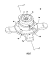
FIG. 2 is a perspective view of the instrument securement device ofFIG. 1 ; -
FIG. 3 is a side, cross-sectional view taken along the line 3-3 ofFIG. 2 illustrating the locking mechanism in an unlocked position and a channel of the ball joint in an unsecured configuration; -
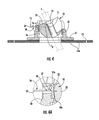
FIG. 4 is a side, cross-sectional view illustrating the locking mechanism ofFIG. 3 in a first locked position and the channel in an unsecured configuration; -
FIG. 5 is a side, cross-sectional view illustrating the locking mechanism ofFIG. 3 in a second locked position and the channel in a secured configuration; -
FIG. 6 is a perspective view of another illustrative embodiment of an instrument fixation device provided in accordance with the present disclosure including a base, a ball joint, and at locking mechanism in an first locked position; and -
FIG. 7 is a side, cross-sectional view of taken along the line 7-7 ofFIG. 6 illustrating the threaded channel of the instrument fixation device and the locking mechanism in a first locked position. - In accordance with the present disclosure, a surgical positioning system includes an instrument fixation device that is detectable by the surgical position system such that the position of the instrument fixation device within a surgical environment is known by the surgical positioning system. The surgical positioning system may include surgical instruments that are positionable relative to the instrument fixation device such that the instrument fixation device fixes the surgical instrument within the surgical site. The surgical positioning system may determine the position of the surgical instrument within the surgical site based on the length of a surgical instrument inserted through the instrument fixation device, the angle of the surgical instrument relative to the surgical positioning system, and the position of the instrument fixation device.
- Embodiments of the present disclosure are now described in detail with reference to the drawings in which like reference numerals designate identical or corresponding elements in each of the several views. As used herein, the term "clinician" refers to a doctor, a nurse, or any other care provider and may include support personnel. Throughout this description, the term "proximal" refers to the portion of the device or component thereof that is closest to the clinician and the term "distal" refers to the portion of the device or component thereof that is farthest from the clinician.
- Referring now to
FIG. 1 , asurgical positioning system 100 is provided in accordance with the present disclosure and includes aninstrument fixation device 10, atracking module 102,reference sensors 106, areference mat 108, and asurgical instrument 120. Thesurgical positioning system 100 is configured to determine the position of thesurgical instrument 120 within a surgical site of the patient P. - The
tracking module 102 may utilize a Six Degrees Of Freedom (SDOF) electromagnetic position measuring system according to the teachings ofU.S. Pat. No. 6,188,355 and publishedPCT Application Nos. WO 00/10456 WO 01/67035 reference mat 108 may be an electromagnetic filed transmitter positioned beneath the patient "P." Thereference sensors 106 are placed on the patient "P" such that their location within the electromagnetic field generated by thereference mat 108 can be detected. The location of eachsensor 106 is determined in and sent to trackingmodule 102. One of skill in the art will recognize that thetracking module 102 may be incorporated into acomputer 104 as a software component and need not be a separate component as depicted inFIG. 1 . - The
instrument fixation device 10 is configured to secure to the skin of the patient P about a surgical site and provide an indication of its position to thetracking module 102. The surgical site may be a natural orifice or an incision in the skin of a patient. Thesurgical positioning system 100 may use the position of theinstrument fixation device 10 to determine the position of thesurgical instrument 120 within the surgical site as detailed below. - With reference to
FIGS. 2 and3 , theinstrument fixation device 10 includes abase 12, a ball joint 20, and alocking mechanism 30. Thebase 12 includes amalleable pad 13 and a retainingring 16. Themalleable pad 13 may be integrally formed with the retainingring 16. Alternatively or additionally, themalleable pad 13 may be secured to the retainingring 16 with adhesive or fasteners 16a. Themalleable pad 13 includes two ormore wings 14 configured to secure thedevice 10 to the skin of the patient P. Themalleable pad 13 may be constructed of a soft material. Themalleable pad 13 may have an anti-microbial coating or be made entirely of an anti-microbial material to reduce the risk of bacterial infection at the surgical site. One or more of thewings 14 may define asuture hole 15 through the upper and lower surface thereof such that a clinician may pass a suture (not shown) through thesuture hole 15 to secure theinstrument fixation device 10 to the patient. Alternatively or additionally, the lower surface of themalleable pad 13 may include an adhesive 13a to secure theinstrument fixation device 10 to the patient. - The ball joint 20 is disposed within a through
passage 19 defined by the retainingring 16. The ball joint 20 is substantially spherical in shape and may include a flattenedupper surface 21. The ball joint 20 is configured to move within the retainingring 16 and may be moveable in SDOF relative to the retainingring 16. The ball joint 20 defines a throughchannel 24 and includes two ormore lobes 22 and alower ring 23. Thelobes 22 are integrally formed with thelower ring 23 and positioned radially about thechannel 24. Thechannel 24 is configured to receive an instrument I (e.g., instrument 120). The flattenedupper surface 21 may define adepression 26 about thechannel 24 to guide the instrument "I" into thechannel 24. - With particular reference to
FIGS. 3 and 3A , the retainingring 16 includes abase flange 17 and aring portion 18. The retainingring 16 and themalleable pad 13 define the throughpassage 19 substantially orthogonal to thebase flange 17 and themalleable pad 13 to provide access to the surgical site through theinstrument fixation device 10. Thering portion 18 may include aretention finger 18a extending towards the throughpassage 19 adjacent an upper surface thereof. Theretention finger 18a is configured to secure the ball joint 16 and thelocking mechanism 30 to thebase 12. - The
locking mechanism 30 includes a lockingsleeve 32 and alock 36. The lockingsleeve 32 is disposed within thering portion 18 of the retainingring 16 and is secured by theretention finger 18a. A portion of thering portion 18 includes alock mount 35. The lockingsleeve 32 is positioned within the retainingring 16 and includes locking fingers 33 extending upward about the outer surface of the ball joint 20. The lockingsleeve 32 may be in contact with the outer surface of the ball joint 20 such that the locking fingers 33 retain the ball joint 20 while permitting the ball joint 20 to move within the locking mechanism. - Referring now to
FIGS. 3 and 3A , thelock 36 may be a lever including anengagement portion 37, apivot 38, and atab 39. Thelock mount 35 secures thelock 36 to thering portion 18. Theengagement portion 37 is configured to contact the outer surface of the lockingsleeve 32. Thedistal tip 37a of theengagement portion 37 may be contoured to conform to the shape of the outer surface of the lockingsleeve 32. Thepivot 38 is substantially aligned in a plane Cp with the center of rotation Cr of the ball joint 20. - With reference to
FIGS. 3-5A , the locking mechanism has an unlocked position (FIG. 3 ), a first locked position (FIG. 4 ), and a second locked position (FIG. 5 ). In the unlocked position of thelocking mechanism 30, shown inFIGS. 3 and 3A , the ball joint 20 is moveable within the lockingsleeve 32 and thechannel 24 is in an unsecured configuration such that a surgical instrument is insertable through the channel 24 (i.e., the surgical instrument "I" is free to slide or rotate within the channel 24). In the unlocked position, the lockingsleeve 32 may partially frictionally interfere with the ball joint 20 such that the ball joint 20, and instrument "I" inserted therethrough, are retained in position relative to the retainingring 16 until an external force is applied to the ball joint 20 or instrument "I" (e.g., the ball joint 20 resists environmental forces but is free to move within the retainingring 16 in response to force applied by a clinician). The lockingsleeve 32 may engage theengagement portion 37 to bias thelocking mechanism 30 into the unlocked position when thelock 36 is between the unlocked position and the first locked position. As represented by arrow F1 inFIG. 3 , a clinician engages thetab 39 of thelock 36 to transition thelocking mechanism 30 to the first locked position. - In the first locked position of the
locking mechanism 30, shown inFIGS. 4 and 4A , the ball joint 20 is fixed relative to the lockingsleeve 32 and thechannel 24 is in the unsecured configuration. In the first locked position, thelock 36 may be substantially parallel to thebase flange 17. Theengagement portion 37 of thelock 36 engages the outer surface of the lockingsleeve 32 such that the contour of thedistal tip 37a matches the contour of the outer surface of the ball joint 20 to maintain thelocking mechanism 30 in the first locked position. The engagement of thedistal tip 37a with the lockingsleeve 32 may provide indicia to a clinician (e.g., tactile feedback) that thelocking mechanism 30 is in the first locked position. - As represented by arrow F2 in
FIG. 4 , a clinician engages thetab 39 of thelock 36 to transition thelocking mechanism 30 from the first locked position to the second locked position. In the second locked position of thelocking mechanism 30, shown inFIGS. 5 and 5A , the ball joint 20 is fixed relative to the lockingsleeve 32 and thechannel 24 is in a secured configuration such that a surgical instrument "I" is fixed within the channel 24 (i.e., the surgical instrument "I" is prevented from sliding or rotating within the channel 24). Thechannel 24 of the ball joint 20 may be a deformable channel. In the second locked position, the lockingsleeve 32 may urge thelobes 22 inward deforming thechannel 24 to fix the surgical instrument "I" within thechannel 24. The lockingsleeve 32 may engage theengagement portion 37 to bias thelocking mechanism 30 into the second locked position when thelock 36 is between the first locked position and the second locked position. - With particular reference to
FIGS. 5 and 5A , theinstrument fixation device 10 may include one ormore sensors 19a-d to provide an indication of a position of or a condition of theinstrument fixation device 10. Aposition sensor 19a may provide an indication of the position of theinstrument fixation device 10 relative to the reference pad 108 (FIG. 1 ) or the sensors 106 (FIG. 1 ). Theinstrument fixation device 10 may include a plurality ofposition sensors 19a positioned on or within the instrument fixation device 10 (e.g., asensor 19a may be associated with eachwing 14, with the retainingring 16, or with the ball joint 20). Thetracking module 102 may determine the position or orientation of theinstrument fixation device 10 from the positions of the plurality ofposition sensors 19a relative to thereference mat 108. In addition, thelocking mechanism 30 may include alock sensor 19b to provide an indication of the position of thelocking mechanism 30 to thetracking module 102. Further, one or moreangular sensors 19c may be associated with the ball joint 20 to provide an indication of the alignment of thechannel 24 relative to the retainingring 16. Moreover, aninstrument sensor 19d may be operatively associated with thechannel 24 to provide an indication of the presence of an instrument within the channel 24 (e.g., the instrument I) and/or the condition of the channel 24 (i.e., secured or unsecured). Theinstrument sensor 19d may also provide an indication of a length of an instrument extending through thechannel 24 and into the surgical site. Theinstrument sensor 19d may detect reference points on an outer surface of an instrument inserted through thechannel 24 or theinstrument sensor 19d may have a roller (not shown) that engages the outer surface of an instrument inserted through thechannel 24. It is within the scope of this disclosure that each of thesensors 19 provide an indication as detailed above with respect tosensors 19a-d. - The
tracking module 102 may be configured to determine the position of a surgical instrument within the surgical site. For example, thetracking module 120 may receive an indication of the position of theinstrument fixation device 10, the orientation of theinstrument fixation device 10, the alignment of thechannel 24 relative to theinstrument fixation device 10, and the length of theinstrument 120 extending from thechannel 24 to determine the position of thesurgical instrument 120 within the surgical site. Thetracking module 102 may receive a signal from one or more of thesensors 19 providing an indication of a position of or a condition of theinstrument fixation device 10. Thetracking module 102 may receive a signal for one or more of thesensors 19a-d and thesensors 106 by a direct (i.e., wired connection) or a wireless connection. The wireless connection may be via radio frequency, optical, WIFI, Bluetooth®, creating personal area networks (PANs)), etc. It is within the scope of this disclosure that the instrument I may act as an antenna for thesensors 19a-d. - With reference to
FIGS. 1-5A , thereference pad 108 is placed on a surgical table 110. Thereference pad 108 may be integral to the surgical table 110. A patient is positioned on the surgical table 110 over thereference pad 108. The plurality ofsensors 106 are positioned at reference points on the patient P. The plurality ofsensors 106 provides an indication of the alignment of the patient P relative to the surgical table 110 to thetracking module 102. Thetracking module 102 may align presurgical scans (e.g., X-rays, CT scans, MRIs, etc.) of the patient with the alignment of the patient P on the surgical table 110. - The
instrument fixation device 10 is positioned and orientated about the surgical site of the patient P. Thetracking module 102 orcomputer 104 may determine the surgical site from the alignment of the patient P on the surgical table 110 and from the presurgical scans. Thetracking module 102 may receive a signal from one ormore sensors 19a-d of theinstrument fixation device 10 while theinstrument fixation device 10 is positioned about the surgical site and provide an indication to the clinician when theinstrument fixation device 10 is positioned and orientated about the surgical site. When theinstrument fixation device 10 is positioned and orientated about the surgical site, a clinician secures theinstrument fixation device 10 to the patient P as detailed above with thelocking mechanism 30 of theinstrument fixation device 10 in an unlocked position. - An instrument (e.g., instrument 120) is inserted through the
channel 24 of theinstrument fixation device 30. Thechannel 24 of theinstrument fixation device 10 is aligned in a desired orientation relative to the surgical site. The desired orientation of thechannel 24 may be predetermined from the presurgical scans. An indication of the alignment of thechannel 24 with the surgical site is provided to thetracking module 102 bysensors 19a-d. Thechannel 24 may be aligned before or after the instrument is inserted through the channel. When thechannel 24 is aligned before the instrument is inserted through thechannel 24, thelocking mechanism 30 is locked in the first locked position to fix thechannel 24 relative to the surgical site before the instrument is inserted through thechannel 24. When thechannel 24 is aligned after the instrument is inserted through thechannel 24, the instrument may be used to align thechannel 24 before thelocking mechanism 30 is locked in the first locked position. When lockingmechanism 30 is in the first locked position with the instrument inserted through thechannel 24, a length of the instrument is inserted through thechannel 24 to a desired depth within the surgical site. The desired depth may be predetermined from the presurgical scans. An indication of the length of the instrument inserted through thechannel 24 and into the surgical site is provided to thetracking module 102 bysensors 19a-d. When the instrument is at the desired depth within the surgical site, thelocking mechanism 30 is locked in the second locking position to secure the instrument within thechannel 24. Thetracking module 102 or thecomputer 104 may provide an indication that the instrument is at the desired depth. - Referring to
FIGS. 6 and7 , anotherinstrument locking device 60 is provided in accordance with the present disclosure including abase 62, a ball joint 70, and alocking mechanism 80. Thebase 62, the ball joint 70, and thelocking mechanism 80 are substantially similar to thebase 12, the ball joint 20, and thelocking mechanism 30 detailed above with respect toinstrument locking device 10, as such only the differences will be detailed below for reasons of brevity. Theinstrument fixation device 60 may further include a plurality ofsensors 19a-d as detailed above. - The
base 62 includes a retainingring 66 that defines a threadedhole 81. The ball joint 70 is substantially spherical in shape and may include a flattenedupper surface 81. The ball joint defines achannel 74 includesthreads 75 for threadably receive an instrument I (e.g., instrument 120). The length of the instrument I extending through thechannel 74 may be determined and fixed by the cooperation of thethreads 75 of the threadedchannel 74 and threads of the instrument (not shown). Thelocking mechanism 80 includes alock 86 in the form of a screw. Thelock 86 includes threads 86a that cooperate with the threads of the threadedhole 81 such that anengagement portion 87 of thelock 86 is configured to fix the ball joint 70 relative to the retainingring 66. Theengagement portion 87 may directly engage the ball joint 70 or engage a locking sleeve 82 positioned about the ball joint 70. - In an unlocked position of the
locking mechanism 80, theengagement portion 87 of thelock 86 is positioned such that the ball joint 70 is moveable within the retainingring 66. In a first locked position of thelocking mechanism 80, theengagement portion 87 of thelock 86 engages the ball joint 70 to fix the ball joint relative to the retainingring 66 as detailed above. - While several embodiments of the disclosure have been shown in the drawings, it is not intended that the disclosure be limited thereto, as it is intended that the disclosure be as broad in scope as the art will allow and that the specification be read likewise. Any combination of the above embodiments is also envisioned and is within the scope of the appended claims. Therefore, the above description should not be construed as limiting, but merely as exemplifications of particular embodiments. Those skilled in the art will envision other modifications within the scope and spirit of the claims appended hereto.
Claims (20)
- An instrument fixation device comprising:a retaining ring;a ball joint having an outer surface and disposed within and moveable relative to the retaining ring, the ball joint defining a channel therethrough;a locking mechanism including:a locking sleeve at least partially disposed within the retaining ring and engagable with the outer surface of the ball joint;a lock including an engagement portion, the locking mechanism having an unlocked position, wherein the ball joint is free to move within the retaining ring, and a first locked position, wherein the locking sleeve engages the outer surface of the ball joint to fix the ball joint relative to the retaining ring.
- The device of claim 1 further comprising a position sensor configured to provide an indication of the location of the device relative to a surgical site.
- The device of claim 1 further comprising an angular sensor configured to provide an indication of the orientation of the ball joint relative to the retaining ring.
- The device of claim 1 further comprising a malleable pad fixed to a bottom surface of the retaining ring.
- The device of claim 4, wherein the malleable pad includes a plurality of wings extending radially away from the retaining ring, at least one of the plurality of wings defining a suture hole configured to receive a suture to secure the device to a patient.
- The device of claim 4, wherein the malleable pad has anti-microbial properties.
- The device of claim 4, wherein a bottom surface of the malleable pad includes an adhesive layer configured to secure the device to a patient.
- The device of claim 1, wherein the ball joint has an unsecured configuration, wherein the channel is configured to slidably and rotatably receive a surgical instrument, and a secured configuration, wherein the channel is configured to fix a surgical instrument relative to the ball joint.
- The device of claim 8, wherein the ball joint includes two or more lobes and the channel is a deformable channel, wherein in the unsecured configuration the deformable channel is undeformed and in the secured configuration, the deformable channel is deformed.
- The device of claim 9, wherein the locking mechanism includes a second locked position wherein the locking sleeve engages the outer surface of the ball joint to fix the ball joint relative to the retaining ring and deforms the deformable channel to the secured configuration.
- The device of claim 1, wherein the ball joint is moveable in six degrees of freedom relative to the retaining ring.
- The device of claim 1, wherein the lock is configured to provide tactile feedback to a clinician when the locking mechanism transitions from the unlocked position to the first locked position.
- The device of claim 1, wherein the lock engages the locking sleeve to engage the locking sleeve with the ball joint.
- A surgical navigation system comprising:a surgical instrument;an instrument fixation device comprising:a retaining ring;a ball joint having an outer surface and disposed within and moveable relative to the retaining ring, the ball joint defining a channel therethrough, the surgical instrument received within the channel and extending into a surgical site;a locking mechanism including:a locking sleeve at least partially disposed within the retaining ring and engagable with the outer surface of the ball joint;a lock including an engagement portion, the locking mechanism having an unlocked position, wherein the ball joint is free to move within the retaining ring and the surgical instrument is free to move relative to the ball joint, and a first locked position, wherein the locking sleeve engages the outer surface of the ball joint to fix the ball joint relative to the retaining ring.
- The system of claim 14, wherein the instrument fixation device includes an instrument sensor configured to provide an indication of a length of the surgical instrument extending through the channel and into a surgical site.
- The system of claim 14, wherein the surgical instrument includes a distal end portion extending from the channel into a surgical site, the instrument fixation device includes a position sensor configured to provide an indication of the position of the instrument fixation device, and wherein the system is configured to determine a length of the surgical instrument extending into a surgical site from the length of the instrument extending from the channel and the position of the instrument fixation device.
- A method for positioning a surgical instrument within a surgical site, the method comprising:securing an instrument fixation device to a patient over a surgical site, the instrument fixation device including:a retaining ring; anda ball joint having an outer surface and disposed within and moveable relative to the retaining ring, the ball joint defining a channel therethrough;inserting a length of a surgical instrument through the channel of the instrument fixation device and into the surgical site;determining the length of the surgical instrument within the surgical site;locking the ball joint relative to the retaining ring with a locking mechanism of the instrument fixation device; andsecuring the surgical instrument relative to the ball joint.
- The method of claim 17, wherein locking the ball joint relative to the retaining ring includes moving a lock of the locking mechanism to a first locked position.
- The method of claim 17, wherein securing the surgical instrument relative to the ball joint includes moving a lock of the locking mechanism to a second locked position.
- The method of claim 17 further comprising providing an indication to a clinician when the instrument fixation device is positioned about the surgical site before securing the instrument fixation device to the patient, the instrument fixation device including a position sensor that provides an indication of the position of the instrument fixation device relative to a surgical site of a patient.
Applications Claiming Priority (1)
| Application Number | Priority Date | Filing Date | Title |
|---|---|---|---|
| US14/326,762 US9629659B2 (en) | 2014-07-09 | 2014-07-09 | Instrument fixation device for depth and angle fixation |
Publications (2)
| Publication Number | Publication Date |
|---|---|
| EP2965700A1 true EP2965700A1 (en) | 2016-01-13 |
| EP2965700B1 EP2965700B1 (en) | 2020-11-25 |
Family
ID=53761189
Family Applications (1)
| Application Number | Title | Priority Date | Filing Date |
|---|---|---|---|
| EP15175746.5A Not-in-force EP2965700B1 (en) | 2014-07-09 | 2015-07-07 | Instrument fixation device for depth and angle fixation |
Country Status (2)
| Country | Link |
|---|---|
| US (2) | US9629659B2 (en) |
| EP (1) | EP2965700B1 (en) |
Cited By (3)
| Publication number | Priority date | Publication date | Assignee | Title |
|---|---|---|---|---|
| WO2018175837A1 (en) * | 2017-03-23 | 2018-09-27 | Gys Tech, Llc, D/B/A Cardan Robotics | Robotic end effector with adjustable inner diameter |
| EP4186448A1 (en) * | 2021-11-25 | 2023-05-31 | Mölnlycke Health Care AB | A trocar fixation assembly |
| EP4268738A1 (en) * | 2022-04-28 | 2023-11-01 | Mölnlycke Health Care AB | An instrument fixation assembly and a trocar fixation system |
Families Citing this family (28)
| Publication number | Priority date | Publication date | Assignee | Title |
|---|---|---|---|---|
| US9480574B2 (en) | 2013-03-14 | 2016-11-01 | Benvenue Medical, Inc. | Spinal fusion implants and devices and methods for deploying such implants |
| MX367291B (en) | 2013-04-24 | 2019-08-13 | Medovex Corp | Minimally invasive methods for spinal facet therapy to alleviate pain and associated surgical tools, kits and instructional media. |
| US10314605B2 (en) | 2014-07-08 | 2019-06-11 | Benvenue Medical, Inc. | Apparatus and methods for disrupting intervertebral disc tissue |
| US9629659B2 (en) | 2014-07-09 | 2017-04-25 | Covidien Lp | Instrument fixation device for depth and angle fixation |
| US10398494B2 (en) | 2014-07-30 | 2019-09-03 | Medovex Corp. | Surgical tools for spinal facet therapy to alleviate pain and related methods |
| AU2015298241B2 (en) | 2014-07-30 | 2019-09-26 | Medovex IP Pty Ltd | Surgical tools for spinal facet therapy to alleviate pain and related methods |
| US10537363B2 (en) * | 2014-10-28 | 2020-01-21 | Cogentix Medical, Inc. | Method and device for controlled delivery of medical devices |
| WO2016069989A1 (en) * | 2014-10-30 | 2016-05-06 | Intuitive Surgical Operations, Inc. | System and method for an articulated arm based tool guide |
| EP3190997B8 (en) * | 2014-12-12 | 2020-04-15 | Medovex Corp. | Surgical tools with positional components |
| US10022243B2 (en) | 2015-02-06 | 2018-07-17 | Benvenue Medical, Inc. | Graft material injector system and method |
| US10702257B2 (en) * | 2015-09-29 | 2020-07-07 | Ethicon Llc | Positioning device for use with surgical instruments |
| WO2017114956A1 (en) * | 2015-12-31 | 2017-07-06 | Koninklijke Philips N.V. | Device for interventional acoustic imaging |
| EP4265220B1 (en) * | 2016-01-08 | 2025-04-30 | Boston Scientific Scimed, Inc. | Device for guiding a surgical instrument |
| US10758286B2 (en) | 2017-03-22 | 2020-09-01 | Benvenue Medical, Inc. | Minimal impact access system to disc space |
| US11583327B2 (en) | 2018-01-29 | 2023-02-21 | Spinal Elements, Inc. | Minimally invasive interbody fusion |
| DE102018103968A1 (en) | 2018-02-22 | 2019-08-22 | Karl Storz Se & Co. Kg | Device for the simultaneous fixation of medical instruments and corresponding system |
| WO2019178575A1 (en) | 2018-03-16 | 2019-09-19 | Benvenue Medical, Inc. | Articulated instrumentation and methods of using the same |
| WO2020073842A1 (en) * | 2018-10-10 | 2020-04-16 | 上海契斯特医疗器械有限公司 | Puncturing positioning device and method for using same |
| EP3685775A1 (en) | 2019-01-25 | 2020-07-29 | CHU de NICE | Trocar fixing device |
| CN109646124B (en) * | 2019-02-15 | 2024-06-07 | 郑州大学第一附属医院 | Magnetic resonance compatible craniocerebral three-dimensional fixing device |
| CN110720971B (en) * | 2019-11-15 | 2024-07-23 | 福建骏格科技有限公司 | Puncture fixed bolster |
| CN112006774B (en) * | 2020-07-28 | 2024-09-20 | 常州锦瑟医疗信息科技有限公司 | Surgical positioning device |
| CN113648079A (en) * | 2021-08-16 | 2021-11-16 | 山东第一医科大学附属省立医院(山东省立医院) | A fixing device for urological instruments |
| US11937799B2 (en) | 2021-09-29 | 2024-03-26 | Cilag Gmbh International | Surgical sealing systems for instrument stabilization |
| JP2024536169A (en) * | 2021-09-29 | 2024-10-04 | シラグ・ゲーエムベーハー・インターナショナル | Surgical sealing device for natural body orifices |
| WO2023052931A1 (en) * | 2021-09-29 | 2023-04-06 | Cilag Gmbh International | Surgical sealing systems for instrument stabilization |
| CN115005930A (en) * | 2022-07-04 | 2022-09-06 | 路肯(上海)医疗科技有限公司 | Friction-based universal locking structure |
| CN116807533A (en) * | 2023-07-13 | 2023-09-29 | 山东威高手术机器人有限公司 | Operating handle for electric hand-held endoscopic surgical instrument |
Citations (7)
| Publication number | Priority date | Publication date | Assignee | Title |
|---|---|---|---|---|
| US5308352A (en) * | 1989-11-17 | 1994-05-03 | Koutrouvelis Panos G | Stereotactic device |
| WO2000010456A1 (en) | 1998-08-02 | 2000-03-02 | Super Dimension Ltd. | Intrabody navigation system for medical applications |
| US6188355B1 (en) | 1997-12-12 | 2001-02-13 | Super Dimension Ltd. | Wireless six-degree-of-freedom locator |
| WO2001067035A1 (en) | 2000-03-09 | 2001-09-13 | Super Dimension Ltd. | Object tracking using a single sensor or a pair of sensors |
| US20020042595A1 (en) * | 2000-10-11 | 2002-04-11 | Medcanica, Inc. | Method of performing port off-pump beating heart coronary artery bypass surgery |
| US20030028179A1 (en) * | 1998-09-15 | 2003-02-06 | Gregory Piskun | Laparoscopic instruments and trocar systems and related surgical method |
| WO2010017641A1 (en) * | 2008-08-15 | 2010-02-18 | Monteris Medical, Inc. | Trajectory guide |
Family Cites Families (19)
| Publication number | Priority date | Publication date | Assignee | Title |
|---|---|---|---|---|
| US5020933A (en) * | 1989-09-01 | 1991-06-04 | Andronic Devices, Ltd. | Locking mechanism for medical devices |
| US5662613A (en) | 1996-05-14 | 1997-09-02 | Astarita; Denis C. | Endoscopic instrument lock |
| DE19822195C1 (en) | 1998-05-16 | 2000-01-27 | Aesculap Ag & Co Kg | Holding arrangement for surgical instrument |
| US6086603A (en) * | 1998-12-14 | 2000-07-11 | Syntheon, Llc | Luminal port device having internal and external sealing mechanisms |
| US6238124B1 (en) * | 1999-01-13 | 2001-05-29 | Werner O. Merlo | Locking joint mechanism |
| US7323004B2 (en) * | 2002-09-30 | 2008-01-29 | Ethicon, Inc. | Device for providing automatic stitching of an incision |
| US7083626B2 (en) * | 2002-10-04 | 2006-08-01 | Applied Medical Resources Corporation | Surgical access device with pendent valve |
| US8961548B2 (en) | 2005-06-06 | 2015-02-24 | Laprostop, Llc | Safety stop trochar device and system |
| US8430811B2 (en) * | 2008-09-30 | 2013-04-30 | Ethicon Endo-Surgery, Inc. | Multiple port surgical access device |
| AU2007283152A1 (en) | 2006-08-10 | 2008-02-14 | Unomedical A/S | A fixation device for holding a medical instrument |
| US8216211B2 (en) | 2006-10-09 | 2012-07-10 | Brianlab Ag | Holding device for medical instruments |
| JP5160144B2 (en) | 2007-05-18 | 2013-03-13 | オリンパス株式会社 | Body cavity insert fixture |
| US8187178B2 (en) * | 2007-06-05 | 2012-05-29 | Atropos Limited | Instrument access device |
| US20090227843A1 (en) * | 2007-09-12 | 2009-09-10 | Smith Jeffrey A | Multi-instrument access devices and systems |
| US9775641B2 (en) | 2009-10-07 | 2017-10-03 | Umc Utrecht Holding B.V. | Holding device for holding a manually operated medical device |
| US9339339B2 (en) * | 2011-09-16 | 2016-05-17 | Boston Scientific Scimed, Inc. | Medical device and method for conducting a surgery through a body opening |
| US9320872B2 (en) | 2011-10-14 | 2016-04-26 | William F. Urmey | Catheter positioning system |
| US9072501B2 (en) * | 2013-03-15 | 2015-07-07 | Regents Of The University Of Minnesota | Micro-orifice surgical access system |
| US9629659B2 (en) | 2014-07-09 | 2017-04-25 | Covidien Lp | Instrument fixation device for depth and angle fixation |
-
2014
- 2014-07-09 US US14/326,762 patent/US9629659B2/en not_active Expired - Fee Related
-
2015
- 2015-07-07 EP EP15175746.5A patent/EP2965700B1/en not_active Not-in-force
-
2017
- 2017-04-07 US US15/482,132 patent/US10639126B2/en active Active
Patent Citations (7)
| Publication number | Priority date | Publication date | Assignee | Title |
|---|---|---|---|---|
| US5308352A (en) * | 1989-11-17 | 1994-05-03 | Koutrouvelis Panos G | Stereotactic device |
| US6188355B1 (en) | 1997-12-12 | 2001-02-13 | Super Dimension Ltd. | Wireless six-degree-of-freedom locator |
| WO2000010456A1 (en) | 1998-08-02 | 2000-03-02 | Super Dimension Ltd. | Intrabody navigation system for medical applications |
| US20030028179A1 (en) * | 1998-09-15 | 2003-02-06 | Gregory Piskun | Laparoscopic instruments and trocar systems and related surgical method |
| WO2001067035A1 (en) | 2000-03-09 | 2001-09-13 | Super Dimension Ltd. | Object tracking using a single sensor or a pair of sensors |
| US20020042595A1 (en) * | 2000-10-11 | 2002-04-11 | Medcanica, Inc. | Method of performing port off-pump beating heart coronary artery bypass surgery |
| WO2010017641A1 (en) * | 2008-08-15 | 2010-02-18 | Monteris Medical, Inc. | Trajectory guide |
Cited By (6)
| Publication number | Priority date | Publication date | Assignee | Title |
|---|---|---|---|---|
| WO2018175837A1 (en) * | 2017-03-23 | 2018-09-27 | Gys Tech, Llc, D/B/A Cardan Robotics | Robotic end effector with adjustable inner diameter |
| US10682129B2 (en) | 2017-03-23 | 2020-06-16 | Mobius Imaging, Llc | Robotic end effector with adjustable inner diameter |
| US11612439B2 (en) | 2017-03-23 | 2023-03-28 | Mobius Imaging Llc | Robotic end effector with adjustable inner diameter |
| EP4186448A1 (en) * | 2021-11-25 | 2023-05-31 | Mölnlycke Health Care AB | A trocar fixation assembly |
| WO2023094171A1 (en) * | 2021-11-25 | 2023-06-01 | Mölnlycke Health Care Ab | A trocar fixation assembly |
| EP4268738A1 (en) * | 2022-04-28 | 2023-11-01 | Mölnlycke Health Care AB | An instrument fixation assembly and a trocar fixation system |
Also Published As
| Publication number | Publication date |
|---|---|
| US20170209233A1 (en) | 2017-07-27 |
| US10639126B2 (en) | 2020-05-05 |
| EP2965700B1 (en) | 2020-11-25 |
| US20160007979A1 (en) | 2016-01-14 |
| US9629659B2 (en) | 2017-04-25 |
Similar Documents
| Publication | Publication Date | Title |
|---|---|---|
| US10639126B2 (en) | Instrument fixation device for depth and angle fixation | |
| US20250152209A1 (en) | Lateral mass fixation system | |
| US10368928B2 (en) | Bone stabilization systems | |
| US8734338B2 (en) | Minimally invasive retractor and methods of use | |
| US20190209154A1 (en) | Multi-shield spinal access system | |
| US9826992B2 (en) | Multiple portal guide | |
| US8870878B2 (en) | Minimally invasive retractor and methods of use | |
| EP3682826B1 (en) | Locking mechanism for surgical access port | |
| US8267859B2 (en) | Spreader insert for a retractor system | |
| EP2462877B1 (en) | Suturing device with deployable needle | |
| US20060224161A1 (en) | Depth gauge apparatus and methods | |
| US20090222044A1 (en) | Minimally Invasive Retractor Screw and Methods of Use | |
| US20090221878A1 (en) | Minimally Invasive Retractor with Separable Blades and Methods of Use | |
| AU2020363803B2 (en) | Instrument handle for use with instrument alignment feedback system and method | |
| EP3267915B1 (en) | Open latarjet for correction of anterior-inferior glenoid bone loss | |
| US20180064547A1 (en) | Humeral head implant system | |
| US10383609B2 (en) | Surgical instrument for making incisions | |
| KR20080030088A (en) | Transdermal Measuring Equipment | |
| AU2009223607A1 (en) | Interspinous process spacer instrument system with deployment indicator | |
| US20030018340A1 (en) | Method and apparatus for installing cannula | |
| JP7463396B2 (en) | Multishield Spinal Access System | |
| EP2241276A1 (en) | Bendable veress needle assembly | |
| EP2526874B1 (en) | Surgical endocorporeal support assembly | |
| WO2020194347A1 (en) | A device for insertion of guide wire and providing root blocks in endoscopic spine surgery | |
| HK40045151B (en) | Medical instrument for percutaneous release procedures |
Legal Events
| Date | Code | Title | Description |
|---|---|---|---|
| PUAI | Public reference made under article 153(3) epc to a published international application that has entered the european phase |
Free format text: ORIGINAL CODE: 0009012 |
|
| AK | Designated contracting states |
Kind code of ref document: A1 Designated state(s): AL AT BE BG CH CY CZ DE DK EE ES FI FR GB GR HR HU IE IS IT LI LT LU LV MC MK MT NL NO PL PT RO RS SE SI SK SM TR |
|
| AX | Request for extension of the european patent |
Extension state: BA ME |
|
| 17P | Request for examination filed |
Effective date: 20160704 |
|
| RBV | Designated contracting states (corrected) |
Designated state(s): AL AT BE BG CH CY CZ DE DK EE ES FI FR GB GR HR HU IE IS IT LI LT LU LV MC MK MT NL NO PL PT RO RS SE SI SK SM TR |
|
| STAA | Information on the status of an ep patent application or granted ep patent |
Free format text: STATUS: EXAMINATION IS IN PROGRESS |
|
| 17Q | First examination report despatched |
Effective date: 20170705 |
|
| GRAP | Despatch of communication of intention to grant a patent |
Free format text: ORIGINAL CODE: EPIDOSNIGR1 |
|
| STAA | Information on the status of an ep patent application or granted ep patent |
Free format text: STATUS: GRANT OF PATENT IS INTENDED |
|
| INTG | Intention to grant announced |
Effective date: 20200619 |
|
| RIN1 | Information on inventor provided before grant (corrected) |
Inventor name: BHAGAT, SIMRANJEET Inventor name: BHARADWAJ, JEETENDRA |
|
| GRAS | Grant fee paid |
Free format text: ORIGINAL CODE: EPIDOSNIGR3 |
|
| GRAA | (expected) grant |
Free format text: ORIGINAL CODE: 0009210 |
|
| STAA | Information on the status of an ep patent application or granted ep patent |
Free format text: STATUS: THE PATENT HAS BEEN GRANTED |
|
| AK | Designated contracting states |
Kind code of ref document: B1 Designated state(s): AL AT BE BG CH CY CZ DE DK EE ES FI FR GB GR HR HU IE IS IT LI LT LU LV MC MK MT NL NO PL PT RO RS SE SI SK SM TR |
|
| REG | Reference to a national code |
Ref country code: GB Ref legal event code: FG4D |
|
| REG | Reference to a national code |
Ref country code: CH Ref legal event code: EP |
|
| REG | Reference to a national code |
Ref country code: DE Ref legal event code: R096 Ref document number: 602015062427 Country of ref document: DE |
|
| REG | Reference to a national code |
Ref country code: AT Ref legal event code: REF Ref document number: 1337379 Country of ref document: AT Kind code of ref document: T Effective date: 20201215 |
|
| REG | Reference to a national code |
Ref country code: IE Ref legal event code: FG4D |
|
| REG | Reference to a national code |
Ref country code: AT Ref legal event code: MK05 Ref document number: 1337379 Country of ref document: AT Kind code of ref document: T Effective date: 20201125 |
|
| REG | Reference to a national code |
Ref country code: NL Ref legal event code: MP Effective date: 20201125 |
|
| PG25 | Lapsed in a contracting state [announced via postgrant information from national office to epo] |
Ref country code: FI Free format text: LAPSE BECAUSE OF FAILURE TO SUBMIT A TRANSLATION OF THE DESCRIPTION OR TO PAY THE FEE WITHIN THE PRESCRIBED TIME-LIMIT Effective date: 20201125 Ref country code: RS Free format text: LAPSE BECAUSE OF FAILURE TO SUBMIT A TRANSLATION OF THE DESCRIPTION OR TO PAY THE FEE WITHIN THE PRESCRIBED TIME-LIMIT Effective date: 20201125 Ref country code: NO Free format text: LAPSE BECAUSE OF FAILURE TO SUBMIT A TRANSLATION OF THE DESCRIPTION OR TO PAY THE FEE WITHIN THE PRESCRIBED TIME-LIMIT Effective date: 20210225 Ref country code: PT Free format text: LAPSE BECAUSE OF FAILURE TO SUBMIT A TRANSLATION OF THE DESCRIPTION OR TO PAY THE FEE WITHIN THE PRESCRIBED TIME-LIMIT Effective date: 20210325 Ref country code: GR Free format text: LAPSE BECAUSE OF FAILURE TO SUBMIT A TRANSLATION OF THE DESCRIPTION OR TO PAY THE FEE WITHIN THE PRESCRIBED TIME-LIMIT Effective date: 20210226 |
|
| PG25 | Lapsed in a contracting state [announced via postgrant information from national office to epo] |
Ref country code: AT Free format text: LAPSE BECAUSE OF FAILURE TO SUBMIT A TRANSLATION OF THE DESCRIPTION OR TO PAY THE FEE WITHIN THE PRESCRIBED TIME-LIMIT Effective date: 20201125 Ref country code: BG Free format text: LAPSE BECAUSE OF FAILURE TO SUBMIT A TRANSLATION OF THE DESCRIPTION OR TO PAY THE FEE WITHIN THE PRESCRIBED TIME-LIMIT Effective date: 20210225 Ref country code: SE Free format text: LAPSE BECAUSE OF FAILURE TO SUBMIT A TRANSLATION OF THE DESCRIPTION OR TO PAY THE FEE WITHIN THE PRESCRIBED TIME-LIMIT Effective date: 20201125 Ref country code: IS Free format text: LAPSE BECAUSE OF FAILURE TO SUBMIT A TRANSLATION OF THE DESCRIPTION OR TO PAY THE FEE WITHIN THE PRESCRIBED TIME-LIMIT Effective date: 20210325 Ref country code: PL Free format text: LAPSE BECAUSE OF FAILURE TO SUBMIT A TRANSLATION OF THE DESCRIPTION OR TO PAY THE FEE WITHIN THE PRESCRIBED TIME-LIMIT Effective date: 20201125 Ref country code: LV Free format text: LAPSE BECAUSE OF FAILURE TO SUBMIT A TRANSLATION OF THE DESCRIPTION OR TO PAY THE FEE WITHIN THE PRESCRIBED TIME-LIMIT Effective date: 20201125 |
|
| REG | Reference to a national code |
Ref country code: LT Ref legal event code: MG9D |
|
| PG25 | Lapsed in a contracting state [announced via postgrant information from national office to epo] |
Ref country code: HR Free format text: LAPSE BECAUSE OF FAILURE TO SUBMIT A TRANSLATION OF THE DESCRIPTION OR TO PAY THE FEE WITHIN THE PRESCRIBED TIME-LIMIT Effective date: 20201125 |
|
| PG25 | Lapsed in a contracting state [announced via postgrant information from national office to epo] |
Ref country code: CZ Free format text: LAPSE BECAUSE OF FAILURE TO SUBMIT A TRANSLATION OF THE DESCRIPTION OR TO PAY THE FEE WITHIN THE PRESCRIBED TIME-LIMIT Effective date: 20201125 Ref country code: EE Free format text: LAPSE BECAUSE OF FAILURE TO SUBMIT A TRANSLATION OF THE DESCRIPTION OR TO PAY THE FEE WITHIN THE PRESCRIBED TIME-LIMIT Effective date: 20201125 Ref country code: SM Free format text: LAPSE BECAUSE OF FAILURE TO SUBMIT A TRANSLATION OF THE DESCRIPTION OR TO PAY THE FEE WITHIN THE PRESCRIBED TIME-LIMIT Effective date: 20201125 Ref country code: LT Free format text: LAPSE BECAUSE OF FAILURE TO SUBMIT A TRANSLATION OF THE DESCRIPTION OR TO PAY THE FEE WITHIN THE PRESCRIBED TIME-LIMIT Effective date: 20201125 Ref country code: RO Free format text: LAPSE BECAUSE OF FAILURE TO SUBMIT A TRANSLATION OF THE DESCRIPTION OR TO PAY THE FEE WITHIN THE PRESCRIBED TIME-LIMIT Effective date: 20201125 Ref country code: SK Free format text: LAPSE BECAUSE OF FAILURE TO SUBMIT A TRANSLATION OF THE DESCRIPTION OR TO PAY THE FEE WITHIN THE PRESCRIBED TIME-LIMIT Effective date: 20201125 |
|
| REG | Reference to a national code |
Ref country code: DE Ref legal event code: R097 Ref document number: 602015062427 Country of ref document: DE |
|
| PG25 | Lapsed in a contracting state [announced via postgrant information from national office to epo] |
Ref country code: DK Free format text: LAPSE BECAUSE OF FAILURE TO SUBMIT A TRANSLATION OF THE DESCRIPTION OR TO PAY THE FEE WITHIN THE PRESCRIBED TIME-LIMIT Effective date: 20201125 |
|
| PLBE | No opposition filed within time limit |
Free format text: ORIGINAL CODE: 0009261 |
|
| STAA | Information on the status of an ep patent application or granted ep patent |
Free format text: STATUS: NO OPPOSITION FILED WITHIN TIME LIMIT |
|
| PG25 | Lapsed in a contracting state [announced via postgrant information from national office to epo] |
Ref country code: AL Free format text: LAPSE BECAUSE OF FAILURE TO SUBMIT A TRANSLATION OF THE DESCRIPTION OR TO PAY THE FEE WITHIN THE PRESCRIBED TIME-LIMIT Effective date: 20201125 Ref country code: NL Free format text: LAPSE BECAUSE OF FAILURE TO SUBMIT A TRANSLATION OF THE DESCRIPTION OR TO PAY THE FEE WITHIN THE PRESCRIBED TIME-LIMIT Effective date: 20201125 Ref country code: IT Free format text: LAPSE BECAUSE OF FAILURE TO SUBMIT A TRANSLATION OF THE DESCRIPTION OR TO PAY THE FEE WITHIN THE PRESCRIBED TIME-LIMIT Effective date: 20201125 |
|
| 26N | No opposition filed |
Effective date: 20210826 |
|
| PG25 | Lapsed in a contracting state [announced via postgrant information from national office to epo] |
Ref country code: ES Free format text: LAPSE BECAUSE OF FAILURE TO SUBMIT A TRANSLATION OF THE DESCRIPTION OR TO PAY THE FEE WITHIN THE PRESCRIBED TIME-LIMIT Effective date: 20201125 Ref country code: SI Free format text: LAPSE BECAUSE OF FAILURE TO SUBMIT A TRANSLATION OF THE DESCRIPTION OR TO PAY THE FEE WITHIN THE PRESCRIBED TIME-LIMIT Effective date: 20201125 |
|
| REG | Reference to a national code |
Ref country code: CH Ref legal event code: PL |
|
| GBPC | Gb: european patent ceased through non-payment of renewal fee |
Effective date: 20210707 |
|
| PG25 | Lapsed in a contracting state [announced via postgrant information from national office to epo] |
Ref country code: MC Free format text: LAPSE BECAUSE OF FAILURE TO SUBMIT A TRANSLATION OF THE DESCRIPTION OR TO PAY THE FEE WITHIN THE PRESCRIBED TIME-LIMIT Effective date: 20201125 |
|
| REG | Reference to a national code |
Ref country code: BE Ref legal event code: MM Effective date: 20210731 |
|
| PG25 | Lapsed in a contracting state [announced via postgrant information from national office to epo] |
Ref country code: LI Free format text: LAPSE BECAUSE OF NON-PAYMENT OF DUE FEES Effective date: 20210731 Ref country code: GB Free format text: LAPSE BECAUSE OF NON-PAYMENT OF DUE FEES Effective date: 20210707 Ref country code: CH Free format text: LAPSE BECAUSE OF NON-PAYMENT OF DUE FEES Effective date: 20210731 |
|
| PG25 | Lapsed in a contracting state [announced via postgrant information from national office to epo] |
Ref country code: IS Free format text: LAPSE BECAUSE OF FAILURE TO SUBMIT A TRANSLATION OF THE DESCRIPTION OR TO PAY THE FEE WITHIN THE PRESCRIBED TIME-LIMIT Effective date: 20210325 Ref country code: LU Free format text: LAPSE BECAUSE OF NON-PAYMENT OF DUE FEES Effective date: 20210707 |
|
| PG25 | Lapsed in a contracting state [announced via postgrant information from national office to epo] |
Ref country code: IE Free format text: LAPSE BECAUSE OF NON-PAYMENT OF DUE FEES Effective date: 20210707 Ref country code: BE Free format text: LAPSE BECAUSE OF NON-PAYMENT OF DUE FEES Effective date: 20210731 |
|
| PG25 | Lapsed in a contracting state [announced via postgrant information from national office to epo] |
Ref country code: HU Free format text: LAPSE BECAUSE OF FAILURE TO SUBMIT A TRANSLATION OF THE DESCRIPTION OR TO PAY THE FEE WITHIN THE PRESCRIBED TIME-LIMIT; INVALID AB INITIO Effective date: 20150707 |
|
| PG25 | Lapsed in a contracting state [announced via postgrant information from national office to epo] |
Ref country code: CY Free format text: LAPSE BECAUSE OF FAILURE TO SUBMIT A TRANSLATION OF THE DESCRIPTION OR TO PAY THE FEE WITHIN THE PRESCRIBED TIME-LIMIT Effective date: 20201125 |
|
| PGFP | Annual fee paid to national office [announced via postgrant information from national office to epo] |
Ref country code: FR Payment date: 20230724 Year of fee payment: 9 Ref country code: DE Payment date: 20230620 Year of fee payment: 9 |
|
| PG25 | Lapsed in a contracting state [announced via postgrant information from national office to epo] |
Ref country code: MK Free format text: LAPSE BECAUSE OF FAILURE TO SUBMIT A TRANSLATION OF THE DESCRIPTION OR TO PAY THE FEE WITHIN THE PRESCRIBED TIME-LIMIT Effective date: 20201125 |
|
| PG25 | Lapsed in a contracting state [announced via postgrant information from national office to epo] |
Ref country code: MT Free format text: LAPSE BECAUSE OF FAILURE TO SUBMIT A TRANSLATION OF THE DESCRIPTION OR TO PAY THE FEE WITHIN THE PRESCRIBED TIME-LIMIT Effective date: 20201125 |
|
| REG | Reference to a national code |
Ref country code: DE Ref legal event code: R119 Ref document number: 602015062427 Country of ref document: DE |
|
| PG25 | Lapsed in a contracting state [announced via postgrant information from national office to epo] |
Ref country code: DE Free format text: LAPSE BECAUSE OF NON-PAYMENT OF DUE FEES Effective date: 20250201 |
|
| PG25 | Lapsed in a contracting state [announced via postgrant information from national office to epo] |
Ref country code: FR Free format text: LAPSE BECAUSE OF NON-PAYMENT OF DUE FEES Effective date: 20240731 |
|
| PG25 | Lapsed in a contracting state [announced via postgrant information from national office to epo] |
Ref country code: TR Free format text: LAPSE BECAUSE OF FAILURE TO SUBMIT A TRANSLATION OF THE DESCRIPTION OR TO PAY THE FEE WITHIN THE PRESCRIBED TIME-LIMIT Effective date: 20201125 |