EP2965686A2 - Endoscope system - Google Patents
Endoscope system Download PDFInfo
- Publication number
- EP2965686A2 EP2965686A2 EP15176036.0A EP15176036A EP2965686A2 EP 2965686 A2 EP2965686 A2 EP 2965686A2 EP 15176036 A EP15176036 A EP 15176036A EP 2965686 A2 EP2965686 A2 EP 2965686A2
- Authority
- EP
- European Patent Office
- Prior art keywords
- endoscope
- elongated body
- handle
- disposed
- lens
- Prior art date
- Legal status (The legal status is an assumption and is not a legal conclusion. Google has not performed a legal analysis and makes no representation as to the accuracy of the status listed.)
- Granted
Links
Images



Classifications
-
- A—HUMAN NECESSITIES
- A61—MEDICAL OR VETERINARY SCIENCE; HYGIENE
- A61B—DIAGNOSIS; SURGERY; IDENTIFICATION
- A61B1/00—Instruments for performing medical examinations of the interior of cavities or tubes of the body by visual or photographical inspection, e.g. endoscopes; Illuminating arrangements therefor
- A61B1/00064—Constructional details of the endoscope body
- A61B1/00066—Proximal part of endoscope body, e.g. handles
-
- A—HUMAN NECESSITIES
- A61—MEDICAL OR VETERINARY SCIENCE; HYGIENE
- A61B—DIAGNOSIS; SURGERY; IDENTIFICATION
- A61B1/00—Instruments for performing medical examinations of the interior of cavities or tubes of the body by visual or photographical inspection, e.g. endoscopes; Illuminating arrangements therefor
- A61B1/00002—Operational features of endoscopes
- A61B1/00011—Operational features of endoscopes characterised by signal transmission
- A61B1/00016—Operational features of endoscopes characterised by signal transmission using wireless means
-
- A—HUMAN NECESSITIES
- A61—MEDICAL OR VETERINARY SCIENCE; HYGIENE
- A61B—DIAGNOSIS; SURGERY; IDENTIFICATION
- A61B1/00—Instruments for performing medical examinations of the interior of cavities or tubes of the body by visual or photographical inspection, e.g. endoscopes; Illuminating arrangements therefor
- A61B1/00002—Operational features of endoscopes
- A61B1/00025—Operational features of endoscopes characterised by power management
- A61B1/00036—Means for power saving, e.g. sleeping mode
-
- A—HUMAN NECESSITIES
- A61—MEDICAL OR VETERINARY SCIENCE; HYGIENE
- A61B—DIAGNOSIS; SURGERY; IDENTIFICATION
- A61B1/00—Instruments for performing medical examinations of the interior of cavities or tubes of the body by visual or photographical inspection, e.g. endoscopes; Illuminating arrangements therefor
- A61B1/00002—Operational features of endoscopes
- A61B1/00039—Operational features of endoscopes provided with input arrangements for the user
- A61B1/00042—Operational features of endoscopes provided with input arrangements for the user for mechanical operation
-
- A—HUMAN NECESSITIES
- A61—MEDICAL OR VETERINARY SCIENCE; HYGIENE
- A61B—DIAGNOSIS; SURGERY; IDENTIFICATION
- A61B1/00—Instruments for performing medical examinations of the interior of cavities or tubes of the body by visual or photographical inspection, e.g. endoscopes; Illuminating arrangements therefor
- A61B1/00064—Constructional details of the endoscope body
- A61B1/00071—Insertion part of the endoscope body
- A61B1/0008—Insertion part of the endoscope body characterised by distal tip features
-
- A—HUMAN NECESSITIES
- A61—MEDICAL OR VETERINARY SCIENCE; HYGIENE
- A61B—DIAGNOSIS; SURGERY; IDENTIFICATION
- A61B1/00—Instruments for performing medical examinations of the interior of cavities or tubes of the body by visual or photographical inspection, e.g. endoscopes; Illuminating arrangements therefor
- A61B1/04—Instruments for performing medical examinations of the interior of cavities or tubes of the body by visual or photographical inspection, e.g. endoscopes; Illuminating arrangements therefor combined with photographic or television appliances
- A61B1/05—Instruments for performing medical examinations of the interior of cavities or tubes of the body by visual or photographical inspection, e.g. endoscopes; Illuminating arrangements therefor combined with photographic or television appliances characterised by the image sensor, e.g. camera, being in the distal end portion
-
- A—HUMAN NECESSITIES
- A61—MEDICAL OR VETERINARY SCIENCE; HYGIENE
- A61B—DIAGNOSIS; SURGERY; IDENTIFICATION
- A61B1/00—Instruments for performing medical examinations of the interior of cavities or tubes of the body by visual or photographical inspection, e.g. endoscopes; Illuminating arrangements therefor
- A61B1/06—Instruments for performing medical examinations of the interior of cavities or tubes of the body by visual or photographical inspection, e.g. endoscopes; Illuminating arrangements therefor with illuminating arrangements
- A61B1/0661—Endoscope light sources
- A61B1/0676—Endoscope light sources at distal tip of an endoscope
-
- A—HUMAN NECESSITIES
- A61—MEDICAL OR VETERINARY SCIENCE; HYGIENE
- A61B—DIAGNOSIS; SURGERY; IDENTIFICATION
- A61B1/00—Instruments for performing medical examinations of the interior of cavities or tubes of the body by visual or photographical inspection, e.g. endoscopes; Illuminating arrangements therefor
- A61B1/06—Instruments for performing medical examinations of the interior of cavities or tubes of the body by visual or photographical inspection, e.g. endoscopes; Illuminating arrangements therefor with illuminating arrangements
- A61B1/0661—Endoscope light sources
- A61B1/0684—Endoscope light sources using light emitting diodes [LED]
-
- A—HUMAN NECESSITIES
- A61—MEDICAL OR VETERINARY SCIENCE; HYGIENE
- A61B—DIAGNOSIS; SURGERY; IDENTIFICATION
- A61B1/00—Instruments for performing medical examinations of the interior of cavities or tubes of the body by visual or photographical inspection, e.g. endoscopes; Illuminating arrangements therefor
- A61B1/12—Instruments for performing medical examinations of the interior of cavities or tubes of the body by visual or photographical inspection, e.g. endoscopes; Illuminating arrangements therefor with cooling or rinsing arrangements
- A61B1/128—Instruments for performing medical examinations of the interior of cavities or tubes of the body by visual or photographical inspection, e.g. endoscopes; Illuminating arrangements therefor with cooling or rinsing arrangements provided with means for regulating temperature
-
- G—PHYSICS
- G02—OPTICS
- G02B—OPTICAL ELEMENTS, SYSTEMS OR APPARATUS
- G02B23/00—Telescopes, e.g. binoculars; Periscopes; Instruments for viewing the inside of hollow bodies; Viewfinders; Optical aiming or sighting devices
- G02B23/24—Instruments or systems for viewing the inside of hollow bodies, e.g. fibrescopes
- G02B23/2407—Optical details
- G02B23/2423—Optical details of the distal end
-
- G—PHYSICS
- G02—OPTICS
- G02B—OPTICAL ELEMENTS, SYSTEMS OR APPARATUS
- G02B23/00—Telescopes, e.g. binoculars; Periscopes; Instruments for viewing the inside of hollow bodies; Viewfinders; Optical aiming or sighting devices
- G02B23/24—Instruments or systems for viewing the inside of hollow bodies, e.g. fibrescopes
- G02B23/2407—Optical details
- G02B23/2461—Illumination
-
- A—HUMAN NECESSITIES
- A61—MEDICAL OR VETERINARY SCIENCE; HYGIENE
- A61B—DIAGNOSIS; SURGERY; IDENTIFICATION
- A61B1/00—Instruments for performing medical examinations of the interior of cavities or tubes of the body by visual or photographical inspection, e.g. endoscopes; Illuminating arrangements therefor
- A61B1/00002—Operational features of endoscopes
- A61B1/00004—Operational features of endoscopes characterised by electronic signal processing
- A61B1/00006—Operational features of endoscopes characterised by electronic signal processing of control signals
-
- G—PHYSICS
- G02—OPTICS
- G02B—OPTICAL ELEMENTS, SYSTEMS OR APPARATUS
- G02B23/00—Telescopes, e.g. binoculars; Periscopes; Instruments for viewing the inside of hollow bodies; Viewfinders; Optical aiming or sighting devices
- G02B23/24—Instruments or systems for viewing the inside of hollow bodies, e.g. fibrescopes
- G02B23/2407—Optical details
- G02B23/2423—Optical details of the distal end
- G02B23/243—Objectives for endoscopes
Definitions
- the present disclosure relates to endosurgical devices and systems for observing internal features of a body during minimally invasive surgical procedures, and more particularly, to endoscope systems and the like.
- Endoscopes are introduced through an incision or a natural body orifice to observe internal features of a body.
- Conventional endoscopes include a light transmission pathway, including a fiber guide, for transmitting light from an external light source through the endoscope to illuminate the internal features of the body.
- Conventional endoscopes also include an image retrieval pathway for transmitting images of these internal features back to an eyepiece or external video system for processing and display on an external monitor.
- the present disclosure is directed to endoscopes and endoscope systems having a light source and camera integrated into a distal end portion of the endoscopes and an integrated processor disposed within a handle of the endoscopes for controlling the endoscope systems.
- an endoscope includes a handle and an elongated body extending distally from the handle.
- the elongated body includes a distal portion terminating at a distal end.
- An image sensor is disposed within the distal portion of the elongated body; a lens is disposed at the distal end of the elongated body, and a light source including one or more light emitting elements is integrated into the distal end of the elongated body and positioned radially outward of the lens.
- the light emitting elements are disposed in a crescent shape around a portion of the lens.
- the light emitting elements may be LEDs.
- the image sensor may be a backside illuminated sensor.
- the image sensor is a high definition CMOS sensor.
- the lens may be a focus free lens.
- the endoscope may include a passive thermal control system.
- a thermally conductive substrate is affixed to the light source.
- a heat sink may be placed in contact with the thermally conductive substrate.
- a thermally conductive adhesive is disposed between the heat sink and the thermally conductive substrate.
- the heat sink is cylindrical in shape and positioned in full contact with a cylindrical wall of the elongated body.
- the endoscope includes a processor disposed within the handle.
- the processor includes a system controller, an imaging subsystem, a video processing subsystem, and peripheral controllers for transmitting data to and from external devices, such as the image sensor and the light source.
- the processor is a system-on-chip.
- an endoscope includes a handle including a handle housing including a grip portion and a control portion.
- the handle housing defines an inner chamber containing a plurality of circuit boards for powering and controlling the endoscope system.
- the handle housing includes: a main board including a processor and memory for system control, data capture, image processing, and video output; a power board including an integrated power chip to manage system power; a button board to enable/disable user controls; and a switch board to power the system on and off.
- the button board may be positioned in the control portion of the handle and the main board may be positioned in the grip portion of the handle.
- the power board is disposed in the grip portion of the handle, and in certain embodiments, the switch board is positioned in the grip portion of the handle.
- the endoscope may further include an elongated body extending distally from the handle.
- the elongated body includes a camera including an image sensor disposed in a distal portion of the elongated body and a lens disposed at the distal end of the elongated body.
- the elongated body also includes a light source disposed at a distal end of the elongated body.
- the processor includes a peripheral controller for controlling the transmission of data between the processor and the camera and a peripheral controller for controlling the transmission of data between the processor and the light source.
- distal refers to that portion of a structure that is farther from a user
- proximal refers to that portion of a structure that is closer to the user.
- subject refers to a human patient or other animal.
- clinical care provider refers to a doctor, nurse, or other care provider and may include support personnel.
- about shall be understood as a word of approximation that takes into account relatively little to no variation in a modified term (e.g., differing by less than 2%).
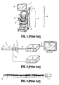
- a prior art endoscope system 1 includes an endoscope 10, a light source 20, a video system 30, and a display device 40.
- the light source 20, such as an LED/Xenon light source is connected to the endoscope 10 via a fiber guide 22 that is operatively coupled to the light source 20 and to an endocoupler 16 disposed on, or adjacent to, a handle 18 of the endoscope 10.
- the fiber guide 22 includes, for example, fiber optic cable which extends through the elongated body 12 of the endoscope 10 and terminates at a distal end 14 of the endoscope 10.
- the fiber guide 22 may be about 1 m to about 1.5 m in length, only about 15% (or less) of the light flux emitted from the light source 20 is outputted from the distal end 14 of the endoscope 10.
- the video system 30 is operatively connected to an image sensor 32 mounted to, or disposed within, the handle 18 of the endoscope 10 via a data cable 34.
- An objective lens 36 is disposed at the distal end 14 of the elongated body 12 of the endoscope 10 and a series of spaced-apart, relay lenses 38, such as rod lenses, are positioned along the length of the elongated body 12 between the objective lens 36 and the image sensor 32. Images captured by the objective lens 36 are forwarded through the elongated body 12 of the endoscope 10 via the relay lenses 38 to the image sensor 32, which are then communicated to the video system 30 for processing and output to the display device 40 via cable 39.
- the image sensor 32 is located within, or mounted to, the handle 18 of the endoscope 10, which can be up to about 30 cm away from the distal end 14 of the endoscope 10, there is loss of image information in the image retrieval pathway as it is difficult to get a high quality image at every point along the whole working distance of the relay lenses 38.
- the objective lens 36 cannot include a small aperture. Therefore, the depth of field is limited and a focusing module (not shown) is typically utilized in the endocoupler 16 to set the objective lens 36 to a desired focal point, which a clinician must adjust when moving the endoscope 10 during a surgical procedure.
- rotation of the fiber guide 22 will also rotate the relay lenses 38, which changes the viewing angle during use, and the fiber guide 22 also tends to fall due to the force of gravity. Accordingly, a clinician needs to adjust and/or hold the fiber guide 22 during use to keep the view stable, which is inconvenient during operation.
- another prior art endoscope system 1' which is substantially similar to endoscope system 1 and therefore will only be described with respect to the differences therebetween, includes the image sensor 32 in a distal portion 13 of the elongated body 12 of the endoscope 10' such that the image retrieval pathway between the objective lens 36 and the image sensor 32 is shorter than that of the endoscope system 1.
- the endoscope system 1' adopts the same light transmission pathway as that of the endoscope system 1 (i.e., from the light source 20 and through the fiber guide 22), and thus light consumption on transmission is still large.
- the fiber guide 22 may be integrated with the data cable 34, thereby making the endoscope 10' easier to operate as a clinician does not need to adjust the fiber guide 22 during use.
- an endoscope system 100 of the present disclosure includes an endoscope 110, a display 120, and a cable 130 connecting the endoscope 110 and the display 120.
- a camera 140, a light source 150, and an integrated processor 160 are contained within the endoscope 110.
- the endoscope 110 includes a handle 112 and an elongated body 114 having a cylindrical wall 114a extending distally from the handle 112 along a longitudinal axis "x."
- the elongated body 114 includes a distal portion 116 terminating at a distal end or tip 118.
- the handle 112 includes a handling housing 112a including a grip portion 113 for handling by a clinician and a control portion 115 including actuating elements 115a (e.g., buttons, switches etc.) for functional control of the endoscope 110.
- the camera 140 is disposed within the elongated body 114 of the endoscope 110.
- the camera 140 includes an image sensor 142 disposed within the distal portion 116 of the elongated body 112 proximal of a lens 144 that is positioned at the distal end 118.
- the image sensor 142 may be a charge-coupled device (CCD), a complementary metal-oxide-semiconductor (CMOS), or a hybrid thereof.
- CMOS complementary metal-oxide-semiconductor
- the image sensor 142 is a highly sensitive, backside illuminated sensor (BSI).
- the lighting flux required by the image sensor 142 may be up to about 20 lm.
- the lens 144 may include a depth of field from about 20mm to about 110mm with optimized image quality and a field-of-view of about 100 degrees.
- the lens 144 is a focus free lens.
- a focus free lens relies on depth of field to produce sharp images and thus, eliminates the need to determine the correct focusing distance and setting the lens to that focal point.
- the aperture of the lens 144 can be relatively small, taking up less space at the distal end 118 of the elongated body 114.
- the outer diameter of the lens 144 is up to about 6 mm.
- the light source 150 is disposed at the distal end 118 of the endoscope 110.
- Light source 150 includes one or more high efficiency light emitting elements 152, such as light-emitting diodes (LED).
- the light emitting elements 152 have a luminous efficacy of up to about 80 lm/W (lumen/watt).
- the light source of the present disclosure eliminates the need for the use of an external light source and fiber guide, which can lower the cost of the endoscope system, simplify the endoscope system structure, and reduce light consumption and/or light distortion during light transmission.
- the light emitting elements 152 are arranged radially outward of the lens 144 at the distal end 118 of the elongated body 114 of the endoscope 110.
- the light source 150 may include a plurality of individual light emitting elements 152 arranged in an annular ring, such as an LED ring, around the lens 144 ( FIG. 7 ) to ensure adequate and even light distribution.
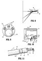
- a distal end 118' of an endoscope 100' may include a plurality of individual light emitting elements 152' arranged in a crescent or arc shape around a portion of the lens 144'.
- the dimensional area of the light source 150 at the distal end 118 of the endoscope may be about, or smaller than, 0.4 cm 2 , with the total light output area being no larger than about 0.1 cm 2 .
- thermal control is managed by reducing heat generation and/or increasing heat conduction.
- Heat generation may be managed, for example, by controlling the luminous efficacy of the light emitting elements 152 and the lighting flux required by the image sensor 142.
- the endoscope 100 of the present disclosure includes high efficiency LED light emitting elements 152 and a BSI CMOS sensor 142.
- the BSI CMOS sensor 142 reduces the lighting flux required to get a bright and clear image in a desired body cavity over image sensors utilized in traditional endoscopes.
- an LED light emitting element 152 with 0.25W power consumption would generate no more than about 0.2W of heat, which is a relatively very small amount of heat that can be controlled by a passive thermal system.
- a passive thermal control system includes a plurality of thermally conductive materials in successive contact with each other so that heat flows from an area of higher temperature to one of lower temperature thereby transporting the excess heat away from the source into the ambient environment.
- a fixture 170 for fixing the lens 144 and a heat sink 172 within the distal portion 116 of the elongated body 114 a thermally conductive substrate 174 in contact with a distal side 172a of the heat sink 172, and a light source 150 affixed to a distal side 174a of the thermally conductive substrate 174.
- Heat generated by the light source 150 is conducted to the thermally conductive substrate 174, the heat sink 172, the cylindrical wall 114a of the elongated body 114, and dissipated into the surrounding air as shown by arrows "A".
- a thin coating of a thermally conductive adhesive 173 may be applied to the distal side 172a of the heat sink 172 to increase the heat conduction between the heat sink 172 and the substrate 174.
- the heat sink 172 may be shaped as a cylinder that is dimensioned to fit within and fully contact the inner surface of the cylindrical wall 114a of the elongated body 114, thereby maximizing the contact area between the heat sink 172 and the cylindrical wall 114a.
- the profile of the heat sink 172 may be designed to match the lens 144 and the light source 150 so that in addition to conducting heat, the heat sink 172 also aids in fixing the lens 144 and the light source 150 within the elongated body 114.
- the integrated processor 160 is designed for master control of the endoscope system 100.
- the processor 160 is an integrated circuit including a system controller 162, various subsystems 164, such as an imaging subsystem 164a and a high definition video processing subsystem 164b, and peripherals 166, such as input/output (I/O) interfaces for controlling data transmission to and/or from external devices, such as the image sensor 142, the light source 150, the actuating elements 115a in the control portion 115 of the handle 112, and the display device 120.
- the processor 160 is also responsible for the configuration and control of memory 168.
- the processor 160 is a system-on-chip (SoC). Compared to traditional hardware architecture, the power consumption of a SoC is low resulting in less heat generation. Accordingly, thermal control of the endoscope is benefitted from a high level integrated, low power consumption SoC.
- SoC system-on-chip
- the processor 160 is configured and designed to capture Full HD raw data from the camera 140 and to transmit the data to the imaging subsystem 164a for video processing, including, for example, color conversion, defect correction, image enhancement, H3A (Auto White Balance, Auto Exposure, and Auto Focus), and resizer.
- the data is then transmitted to the high definition video processing subsystem 164b for wrapping of the processed data, and finally to an HDMI output 169 for image display on the display device 120.
- the hardware modules may be tailored to control power consumption. In embodiments, some hardware functional blocks, such as a high definition video image co-processor 161, and some peripherals 166, such as Ethernet and some I/O interfaces, may be disabled. Such system software optimization of the video pipeline results in lower resource requirements and the tailored hardware modules optimize power consumption for thermal control.
- the hardware structure may include multiple circuit boards to maximize the use of the three dimensional space within the handle housing 112a and/or minimize the dimensional size of the handle 112 to a smaller and lightweight construction.
- the handle 112 defines an inner chamber containing: a main board 180 including the processor 160 and the memory 168 for performing system control, data capture, imaging processing, and video output; a power board 182 including an integrated power chip 182a to manage the system's power; a button board 184 operably associated with the actuating elements 115a of the control portion 115 of the handle 112 for enabling/disabling a user interface on screen display menu, system functional controls and shortcuts; and a switch board 186 for powering the whole system on and off.
- the cable 130 connecting the endoscope 110 and the display 120 may, in addition to the HDMI data pathway, include a power wire and converter for converting alternating current (e.g., 110/220V AC) into direct current (e.g., 5V DC) for system power.
- alternating current e.g., 110/220V AC
- direct current e.g., 5V DC
- An endoscope was constructed which included three high efficiency LEDs having a luminous efficacy of about 80 lm/W and an OV2724 CMOS HD image sensor which is commercially available from OmniVision of Santa Clara, California.
- a passive thermal control system was designed to include the thermally conductive materials provided in Table 1 below. TABLE 1: Thermal Conductive Materials in a Thermal Control System Material Thermal Conductivity (W/m*K) Ceramic substrate 320 Silicone thermal adhesive 2-5 Aluminum heat sink 230 Stainless steel cylindrical wall 16 Air 0.024
- the thermal control of the endoscope of Example 1 was tested by measuring the temperature at the surface of the distal end of the elongated body of the endoscope inside an artificial abdominal cavity having a 298.8K environment temperature after the endoscope was powered-on for 60 minutes. As shown in Table 2 below, the temperature rise was under 10K for a 20lm flux, which means that the temperature at the distal end of the endoscope was not over about 42°C during use.
- Example 1 The lighting stability of the endoscope of Example 1 was tested by continually working the endoscope for over a 72 hour period under the same test conditions of the temperature test of Example 2. As shown in Table 3 below, the temperature was successfully controlled by the passive thermal control system. TABLE 3: Stability Test Results Flux (lm) Voltage (V) Current (mA) Time (h, min) 20.74 7.937 30 0h 00min 21.16 7.936 30 4h 26min 21.01 7.934 30 5h 14min 20.29 7.933 30 22h 56min 20.80 7.933 30 29h 08min 20.64 7.929 30 50h 21min 20.33 7.925 30 74h 01min
Landscapes
- Health & Medical Sciences (AREA)
- Life Sciences & Earth Sciences (AREA)
- Surgery (AREA)
- Physics & Mathematics (AREA)
- Engineering & Computer Science (AREA)
- Optics & Photonics (AREA)
- Medical Informatics (AREA)
- General Health & Medical Sciences (AREA)
- Pathology (AREA)
- Nuclear Medicine, Radiotherapy & Molecular Imaging (AREA)
- Biomedical Technology (AREA)
- Heart & Thoracic Surgery (AREA)
- Biophysics (AREA)
- Molecular Biology (AREA)
- Animal Behavior & Ethology (AREA)
- Radiology & Medical Imaging (AREA)
- Public Health (AREA)
- Veterinary Medicine (AREA)
- Astronomy & Astrophysics (AREA)
- General Physics & Mathematics (AREA)
- Mechanical Engineering (AREA)
- Microelectronics & Electronic Packaging (AREA)
- Computer Networks & Wireless Communication (AREA)
- Endoscopes (AREA)
- Instruments For Viewing The Inside Of Hollow Bodies (AREA)
- Signal Processing (AREA)
Description
- The present disclosure relates to endosurgical devices and systems for observing internal features of a body during minimally invasive surgical procedures, and more particularly, to endoscope systems and the like.
- Endoscopes are introduced through an incision or a natural body orifice to observe internal features of a body. Conventional endoscopes include a light transmission pathway, including a fiber guide, for transmitting light from an external light source through the endoscope to illuminate the internal features of the body. Conventional endoscopes also include an image retrieval pathway for transmitting images of these internal features back to an eyepiece or external video system for processing and display on an external monitor.
- The present disclosure is directed to endoscopes and endoscope systems having a light source and camera integrated into a distal end portion of the endoscopes and an integrated processor disposed within a handle of the endoscopes for controlling the endoscope systems.
- According to an aspect of the present disclosure, an endoscope includes a handle and an elongated body extending distally from the handle. The elongated body includes a distal portion terminating at a distal end. An image sensor is disposed within the distal portion of the elongated body; a lens is disposed at the distal end of the elongated body, and a light source including one or more light emitting elements is integrated into the distal end of the elongated body and positioned radially outward of the lens. In embodiments, the light emitting elements are disposed in a crescent shape around a portion of the lens. The light emitting elements may be LEDs. The image sensor may be a backside illuminated sensor. In embodiments, the image sensor is a high definition CMOS sensor. The lens may be a focus free lens.
- The endoscope may include a passive thermal control system. In embodiments, a thermally conductive substrate is affixed to the light source. A heat sink may be placed in contact with the thermally conductive substrate. In some embodiments, a thermally conductive adhesive is disposed between the heat sink and the thermally conductive substrate. In certain embodiments, the heat sink is cylindrical in shape and positioned in full contact with a cylindrical wall of the elongated body.
- In embodiments, the endoscope includes a processor disposed within the handle. The processor includes a system controller, an imaging subsystem, a video processing subsystem, and peripheral controllers for transmitting data to and from external devices, such as the image sensor and the light source. In embodiments, the processor is a system-on-chip.
- According to another aspect of the present disclosure, an endoscope includes a handle including a handle housing including a grip portion and a control portion. The handle housing defines an inner chamber containing a plurality of circuit boards for powering and controlling the endoscope system. In embodiments, the handle housing includes: a main board including a processor and memory for system control, data capture, image processing, and video output; a power board including an integrated power chip to manage system power; a button board to enable/disable user controls; and a switch board to power the system on and off.
- The button board may be positioned in the control portion of the handle and the main board may be positioned in the grip portion of the handle. In embodiments, the power board is disposed in the grip portion of the handle, and in certain embodiments, the switch board is positioned in the grip portion of the handle.
- The endoscope may further include an elongated body extending distally from the handle. The elongated body includes a camera including an image sensor disposed in a distal portion of the elongated body and a lens disposed at the distal end of the elongated body. The elongated body also includes a light source disposed at a distal end of the elongated body. The processor includes a peripheral controller for controlling the transmission of data between the processor and the camera and a peripheral controller for controlling the transmission of data between the processor and the light source.
- Further details and aspects of exemplary embodiments of the present disclosure are described in more detail below with reference to the appended figures.
- Embodiments of the present disclosure are described herein with reference to the accompanying drawings, wherein:
-
FIG. 1 is a front, perspective view of an endoscope system of the prior art; -
FIG. 2 is front, perspective view illustrating a schematic configuration of the endoscope system ofFIG. 1 ; -
FIG. 3 is a side view illustrating a schematic configuration of an optical system of the endoscope system ofFIG. 1 ; -
FIG. 4 is a front, perspective view illustrating a schematic configuration of another endoscope system of the prior art; -
FIG. 5 is a perspective, partial cutaway view illustrating a schematic configuration of a distal end of an endoscope of the endoscope system ofFIG. 4 ; -
FIG. 6 is a perspective view of an endoscope in accordance with an embodiment of the present disclosure; -
FIG. 7 is a front, perspective view illustrating a schematic configuration of an endoscope system in accordance with an embodiment of the present disclosure; -
FIG. 8 is a schematic illustration of a camera of the endoscope ofFIG. 6 ; -
FIG. 9 is an end view illustrating a schematic configuration of a distal end of an endoscope in accordance with an embodiment of the present disclosure; -
FIG. 10 is a side, cross-sectional view of a distal portion of the endoscope ofFIG. 6 ; -
FIG. 11 is a side, perspective view, with parts separated, of the distal portion of the endoscope ofFIG. 10 ; -
FIG. 12 is a block diagram of system components of the endoscope system ofFIG. 7 ; -
FIG. 13 is a block diagram of an integrated processor ofFIG. 12 ; and -
FIG. 14 is a top, perspective view of a handle of the endoscope ofFIG. 6 . - Embodiments of the presently disclosed endoscope and endoscope system is described in detail with reference to the drawings, in which like reference numerals designate identical or corresponding elements in each of the several views. As used herein, the term "distal" refers to that portion of a structure that is farther from a user, while the term "proximal" refers to that portion of a structure that is closer to the user. As used herein, the term "subject" refers to a human patient or other animal. The term "clinician" refers to a doctor, nurse, or other care provider and may include support personnel. The term "about" shall be understood as a word of approximation that takes into account relatively little to no variation in a modified term (e.g., differing by less than 2%).
- Referring initially to
FIGS. 1-3 , a priorart endoscope system 1 includes anendoscope 10, alight source 20, avideo system 30, and adisplay device 40. Thelight source 20, such as an LED/Xenon light source, is connected to theendoscope 10 via afiber guide 22 that is operatively coupled to thelight source 20 and to anendocoupler 16 disposed on, or adjacent to, ahandle 18 of theendoscope 10. Thefiber guide 22 includes, for example, fiber optic cable which extends through theelongated body 12 of theendoscope 10 and terminates at adistal end 14 of theendoscope 10. Accordingly, light is transmitted from thelight source 20, through thefiber guide 22, and emitted out thedistal end 14 of theendoscope 10 toward a targeted internal feature, such as tissue or an organ, of a body of a patient. As the light transmission pathway in such a configuration is long, for example, thefiber guide 22 may be about 1 m to about 1.5 m in length, only about 15% (or less) of the light flux emitted from thelight source 20 is outputted from thedistal end 14 of theendoscope 10. - The
video system 30 is operatively connected to animage sensor 32 mounted to, or disposed within, thehandle 18 of theendoscope 10 via adata cable 34. Anobjective lens 36 is disposed at thedistal end 14 of theelongated body 12 of theendoscope 10 and a series of spaced-apart,relay lenses 38, such as rod lenses, are positioned along the length of theelongated body 12 between theobjective lens 36 and theimage sensor 32. Images captured by theobjective lens 36 are forwarded through theelongated body 12 of theendoscope 10 via therelay lenses 38 to theimage sensor 32, which are then communicated to thevideo system 30 for processing and output to thedisplay device 40 viacable 39. - As the
image sensor 32 is located within, or mounted to, thehandle 18 of theendoscope 10, which can be up to about 30 cm away from thedistal end 14 of theendoscope 10, there is loss of image information in the image retrieval pathway as it is difficult to get a high quality image at every point along the whole working distance of therelay lenses 38. Moreover, due to light loss on therelay lenses 38, theobjective lens 36 cannot include a small aperture. Therefore, the depth of field is limited and a focusing module (not shown) is typically utilized in theendocoupler 16 to set theobjective lens 36 to a desired focal point, which a clinician must adjust when moving theendoscope 10 during a surgical procedure. Also, rotation of thefiber guide 22 will also rotate therelay lenses 38, which changes the viewing angle during use, and thefiber guide 22 also tends to fall due to the force of gravity. Accordingly, a clinician needs to adjust and/or hold thefiber guide 22 during use to keep the view stable, which is inconvenient during operation. - As shown in
FIGS. 4 and 5 , another prior art endoscope system 1', which is substantially similar toendoscope system 1 and therefore will only be described with respect to the differences therebetween, includes theimage sensor 32 in adistal portion 13 of theelongated body 12 of the endoscope 10' such that the image retrieval pathway between theobjective lens 36 and theimage sensor 32 is shorter than that of theendoscope system 1. The endoscope system 1' adopts the same light transmission pathway as that of the endoscope system 1 (i.e., from thelight source 20 and through the fiber guide 22), and thus light consumption on transmission is still large. However, thefiber guide 22 may be integrated with thedata cable 34, thereby making the endoscope 10' easier to operate as a clinician does not need to adjust thefiber guide 22 during use. - Referring now to
FIGS. 6 and 7 , anendoscope system 100 of the present disclosure includes anendoscope 110, adisplay 120, and acable 130 connecting theendoscope 110 and thedisplay 120. Acamera 140, alight source 150, and anintegrated processor 160 are contained within theendoscope 110. - The
endoscope 110 includes ahandle 112 and anelongated body 114 having acylindrical wall 114a extending distally from thehandle 112 along a longitudinal axis "x." Theelongated body 114 includes adistal portion 116 terminating at a distal end ortip 118. Thehandle 112 includes a handlinghousing 112a including agrip portion 113 for handling by a clinician and acontrol portion 115 includingactuating elements 115a (e.g., buttons, switches etc.) for functional control of theendoscope 110. - As shown in
FIG. 8 , in conjunction withFIG. 7 , thecamera 140 is disposed within theelongated body 114 of theendoscope 110. Thecamera 140 includes animage sensor 142 disposed within thedistal portion 116 of theelongated body 112 proximal of alens 144 that is positioned at thedistal end 118. Theimage sensor 142 may be a charge-coupled device (CCD), a complementary metal-oxide-semiconductor (CMOS), or a hybrid thereof. In embodiments, theimage sensor 142 is a highly sensitive, backside illuminated sensor (BSI). In embodiments, the lighting flux required by theimage sensor 142 may be up to about 20 lm. - As the image retrieval pathway is shortened over that of traditional endoscope systems (e.g.,
FIG. 1 ) and the need for relay lenses is eliminated, the depth of field can be expanded and optimized. Accordingly, thelens 144 may include a depth of field from about 20mm to about 110mm with optimized image quality and a field-of-view of about 100 degrees. In embodiments, thelens 144 is a focus free lens. As compared to traditional endoscopes, a focus free lens relies on depth of field to produce sharp images and thus, eliminates the need to determine the correct focusing distance and setting the lens to that focal point. Accordingly, the aperture of thelens 144 can be relatively small, taking up less space at thedistal end 118 of theelongated body 114. In embodiments, the outer diameter of thelens 144 is up to about 6 mm. - The
light source 150 is disposed at thedistal end 118 of theendoscope 110.Light source 150 includes one or more high efficiencylight emitting elements 152, such as light-emitting diodes (LED). In embodiments, thelight emitting elements 152 have a luminous efficacy of up to about 80 lm/W (lumen/watt). As compared to traditional endoscopes, the light source of the present disclosure eliminates the need for the use of an external light source and fiber guide, which can lower the cost of the endoscope system, simplify the endoscope system structure, and reduce light consumption and/or light distortion during light transmission. - The
light emitting elements 152 are arranged radially outward of thelens 144 at thedistal end 118 of theelongated body 114 of theendoscope 110. Thelight source 150 may include a plurality of individuallight emitting elements 152 arranged in an annular ring, such as an LED ring, around the lens 144 (FIG. 7 ) to ensure adequate and even light distribution. In some embodiments, such as that shown inFIG. 9 , a distal end 118' of an endoscope 100' may include a plurality of individual light emitting elements 152' arranged in a crescent or arc shape around a portion of the lens 144'. The dimensional area of thelight source 150 at thedistal end 118 of the endoscope may be about, or smaller than, 0.4 cm2, with the total light output area being no larger than about 0.1 cm2. To reduce the heat output from such a small area by the high density of light, thermal control is managed by reducing heat generation and/or increasing heat conduction. - Heat generation may be managed, for example, by controlling the luminous efficacy of the
light emitting elements 152 and the lighting flux required by theimage sensor 142. In embodiments, theendoscope 100 of the present disclosure includes high efficiency LEDlight emitting elements 152 and aBSI CMOS sensor 142. TheBSI CMOS sensor 142 reduces the lighting flux required to get a bright and clear image in a desired body cavity over image sensors utilized in traditional endoscopes. Accordingly, in embodiments where, for example, about 20 lm of lighting flux is required, such as within an abdomen of a patient, the power consumption of LEDlight emitting elements 152 having a luminous efficacy of about 80 lm/W will be about 0.25 W (20lm / 80lm/W = 0.25W). As about 80% of the power consumption of an LED is typically turned into heat, an LEDlight emitting element 152 with 0.25W power consumption would generate no more than about 0.2W of heat, which is a relatively very small amount of heat that can be controlled by a passive thermal system. - To increase heat conduction, a passive thermal control system includes a plurality of thermally conductive materials in successive contact with each other so that heat flows from an area of higher temperature to one of lower temperature thereby transporting the excess heat away from the source into the ambient environment. As shown in
FIGS. 10 and 11 , contained within thecylindrical wall 114a of theendoscope 110 is afixture 170 for fixing thelens 144 and aheat sink 172 within thedistal portion 116 of theelongated body 114, a thermallyconductive substrate 174 in contact with adistal side 172a of theheat sink 172, and alight source 150 affixed to adistal side 174a of the thermallyconductive substrate 174. Heat generated by thelight source 150 is conducted to the thermallyconductive substrate 174, theheat sink 172, thecylindrical wall 114a of theelongated body 114, and dissipated into the surrounding air as shown by arrows "A". - In embodiments, a thin coating of a thermally conductive adhesive 173 may be applied to the
distal side 172a of theheat sink 172 to increase the heat conduction between theheat sink 172 and thesubstrate 174. Theheat sink 172 may be shaped as a cylinder that is dimensioned to fit within and fully contact the inner surface of thecylindrical wall 114a of theelongated body 114, thereby maximizing the contact area between theheat sink 172 and thecylindrical wall 114a. The profile of theheat sink 172 may be designed to match thelens 144 and thelight source 150 so that in addition to conducting heat, theheat sink 172 also aids in fixing thelens 144 and thelight source 150 within theelongated body 114. - Referring now to
FIGS. 12 and13 , theintegrated processor 160 is designed for master control of theendoscope system 100. Theprocessor 160 is an integrated circuit including asystem controller 162,various subsystems 164, such as animaging subsystem 164a and a high definitionvideo processing subsystem 164b, andperipherals 166, such as input/output (I/O) interfaces for controlling data transmission to and/or from external devices, such as theimage sensor 142, thelight source 150, theactuating elements 115a in thecontrol portion 115 of thehandle 112, and thedisplay device 120. Theprocessor 160 is also responsible for the configuration and control ofmemory 168. In embodiments, theprocessor 160 is a system-on-chip (SoC). Compared to traditional hardware architecture, the power consumption of a SoC is low resulting in less heat generation. Accordingly, thermal control of the endoscope is benefitted from a high level integrated, low power consumption SoC. - The
processor 160 is configured and designed to capture Full HD raw data from thecamera 140 and to transmit the data to theimaging subsystem 164a for video processing, including, for example, color conversion, defect correction, image enhancement, H3A (Auto White Balance, Auto Exposure, and Auto Focus), and resizer. The data is then transmitted to the high definitionvideo processing subsystem 164b for wrapping of the processed data, and finally to anHDMI output 169 for image display on thedisplay device 120. The hardware modules may be tailored to control power consumption. In embodiments, some hardware functional blocks, such as a high definitionvideo image co-processor 161, and someperipherals 166, such as Ethernet and some I/O interfaces, may be disabled. Such system software optimization of the video pipeline results in lower resource requirements and the tailored hardware modules optimize power consumption for thermal control. - As shown in
FIG. 14 , in conjunction withFIGS. 12 and13 , the hardware structure may include multiple circuit boards to maximize the use of the three dimensional space within thehandle housing 112a and/or minimize the dimensional size of thehandle 112 to a smaller and lightweight construction. Thehandle 112 defines an inner chamber containing: amain board 180 including theprocessor 160 and thememory 168 for performing system control, data capture, imaging processing, and video output; apower board 182 including an integratedpower chip 182a to manage the system's power; abutton board 184 operably associated with theactuating elements 115a of thecontrol portion 115 of thehandle 112 for enabling/disabling a user interface on screen display menu, system functional controls and shortcuts; and aswitch board 186 for powering the whole system on and off. Thecable 130 connecting theendoscope 110 and thedisplay 120 may, in addition to the HDMI data pathway, include a power wire and converter for converting alternating current (e.g., 110/220V AC) into direct current (e.g., 5V DC) for system power. - An endoscope was constructed which included three high efficiency LEDs having a luminous efficacy of about 80 lm/W and an OV2724 CMOS HD image sensor which is commercially available from OmniVision of Santa Clara, California. A passive thermal control system was designed to include the thermally conductive materials provided in Table 1 below.
TABLE 1: Thermal Conductive Materials in a Thermal Control System Material Thermal Conductivity (W/m*K) Ceramic substrate 320 Silicone thermal adhesive 2-5 Aluminum heat sink 230 Stainless steel cylindrical wall 16 Air 0.024 - The thermal control of the endoscope of Example 1 was tested by measuring the temperature at the surface of the distal end of the elongated body of the endoscope inside an artificial abdominal cavity having a 298.8K environment temperature after the endoscope was powered-on for 60 minutes. As shown in Table 2 below, the temperature rise was under 10K for a 20lm flux, which means that the temperature at the distal end of the endoscope was not over about 42°C during use.
TABLE 2: Temperature Test Results Flux (lm) Voltage (V) Current (mA) Temperature (K) Temperature rise (K) 7.29 7.789 10 296.23 2.48 11.17 7.839 15 297.26 3.56 14.54 7.871 20 298.52 5.31 18.74 7.904 25 299.88 6.13 22.43 7.929 30 300.78 7.03 26.14 7.951 35 303.88 10.13 - The lighting stability of the endoscope of Example 1 was tested by continually working the endoscope for over a 72 hour period under the same test conditions of the temperature test of Example 2. As shown in Table 3 below, the temperature was successfully controlled by the passive thermal control system.
TABLE 3: Stability Test Results Flux (lm) Voltage (V) Current (mA) Time (h, min) 20.74 7.937 30 0h 00min 21.16 7.936 30 4h 26min 21.01 7.934 30 5h 14min 20.29 7.933 30 22h 56min 20.80 7.933 30 29h 08min 20.64 7.929 30 50h 21min 20.33 7.925 30 74h 01min - It will be understood that various modifications may be made to the embodiments described herein. Therefore, the above description should not be construed as limiting, but merely as exemplifications of various embodiments. Those skilled in the art will envision other modifications within the scope and spirit of the claims appended thereto.
- The invention may be described by reference to the following numbered paragraphs;
- 1. An endoscope comprising:
- a handle; and
- an elongated body extending distally from the handle, the elongated body including a distal portion terminating at a distal end;
- an image sensor disposed within the distal portion of the elongated body;
- a lens disposed at the distal end of the elongated body; and
- a light source including one or more light emitting elements integrated into the distal end of the elongated body and positioned radially outward of the lens.
- 2. The endoscope of
paragraph 1, wherein the light emitting elements are LEDs. - 3. The endoscope of
paragraph 1, wherein the light emitting elements are disposed in a crescent shape around a portion of the lens. - 4. The endoscope of
paragraph 1, further comprising a thermally conductive substrate affixed to the light source. - 5. The endoscope of paragraph 4, further comprising a heat sink in contact with the thermally conductive substrate.
- 6. The endoscope of paragraph 5, wherein a thermally conductive adhesive is disposed between the heat sink and the thermally conductive substrate.
- 7. The endoscope of paragraph 5, wherein the heat sink is cylindrical in shape and is in full contact with a cylindrical wall of the elongated body.
- 8. The endoscope of
paragraph 1, wherein the image sensor is a backside illuminated sensor. - 9. The endoscope of
paragraph 1, wherein the image sensor is a BSI CMOS sensor. - 10. The endoscope of
paragraph 1, wherein the lens is a focus free lens. - 11. The endoscope of
paragraph 1, further comprising an integrated processor disposed within the handle. - 12. The endoscope of paragraph 11, wherein the processor includes a system controller, an imaging subsystem, a video processing subsystem, and peripheral controllers for transmitting data to and from the image sensor and the light source.
- 13. The endoscope of paragraph 11, wherein the processor is a system-on-chip.
- 14. An endoscope including:
- a handle including a handle housing including a grip portion and a control portion, the handle housing defining an inner chamber containing:
- a main board including a processor and memory for system control, data capture, image processing, and video output;
- a power board including an integrated power chip to manage system power;
- a button board to enable/disable user controls; and
- a switch board to power the endoscope on and off.
- a handle including a handle housing including a grip portion and a control portion, the handle housing defining an inner chamber containing:
- 15. The endoscope of
paragraph 14, wherein the button board is positioned in the control portion of the handle and the main board is positioned in the grip portion of the handle. - 16. The endoscope of paragraph 15, wherein the power board is disposed in the grip portion of the handle.
- 17. The endoscope of
paragraph 16, wherein the switch board is positioned in the grip portion of the handle. - 18. The endoscope of paragraph 15, further comprising:
- an elongated body extending distally from the handle, the elongated body including:
- a camera including an image sensor disposed in a distal portion of the elongated body and a lens disposed at the distal end of the elongated body; and
- a at a distal light source disposed end of the elongated body,
- wherein the processor includes a peripheral controller for controlling the transmission of data between the processor and the camera and a peripheral controller for controlling the transmission of data between the processor and the light source.
- an elongated body extending distally from the handle, the elongated body including:
Claims (15)
- An endoscope comprising:a handle; andan elongated body extending distally from the handle, the elongated body including a distal portion terminating at a distal end;an image sensor disposed within the distal portion of the elongated body;a lens disposed at the distal end of the elongated body; anda light source including one or more light emitting elements integrated into the distal end of the elongated body and positioned radially outward of the lens.
- The endoscope of claim 1, wherein the light emitting elements are LEDs; and/or wherein the light emitting elements are disposed in a crescent shape around a portion of the lens.
- The endoscope of claim 1 or claim 2, further comprising a thermally conductive substrate affixed to the light source; preferably further comprising a heat sink in contact with the thermally conductive substrate.
- The endoscope of claim 3, wherein a thermally conductive adhesive is disposed between the heat sink and the thermally conductive substrate; and/or wherein the heat sink is cylindrical in shape and is in full contact with a cylindrical wall of the elongated body.
- The endoscope of any preceding claim, wherein the image sensor is a backside illuminated sensor.
- The endoscope of any preceding claim, wherein the image sensor is a BSI CMOS sensor.
- The endoscope of any preceding claim, wherein the lens is a focus free lens.
- The endoscope of any preceding claim, further comprising an integrated processor disposed within the handle.
- The endoscope of claim 8, wherein the processor includes a system controller, an imaging subsystem, a video processing subsystem, and peripheral controllers for transmitting data to and from the image sensor and the light source.
- The endoscope of claim 8 or claim 9, wherein the processor is a system-on-chip.
- An endoscope including:a handle including a handle housing including a grip portion and a control portion, the handle housing defining an inner chamber containing:a main board including a processor and memory for system control, data capture, image processing, and video output;a power board including an integrated power chip to manage system power;a button board to enable/disable user controls; anda switch board to power the endoscope on and off.
- The endoscope of claim 11, wherein the button board is positioned in the control portion of the handle and the main board is positioned in the grip portion of the handle.
- The endoscope of claim 11 or claim 12, wherein the power board is disposed in the grip portion of the handle.
- The endoscope of any of claims 11 to 13, wherein the switch board is positioned in the grip portion of the handle.
- The endoscope of claim 14, further comprising:an elongated body extending distally from the handle, the elongated body including:a camera including an image sensor disposed in a distal portion of the elongated body and a lens disposed at the distal end of the elongated body; anda light source disposed at a distal end of the elongated body,wherein the processor includes a peripheral controller for controlling the transmission of data between the processor and the camera and a peripheral controller for controlling the transmission of data between the processor and the light source.
Applications Claiming Priority (2)
| Application Number | Priority Date | Filing Date | Title |
|---|---|---|---|
| US201462022835P | 2014-07-10 | 2014-07-10 | |
| US14/729,664 US10952600B2 (en) | 2014-07-10 | 2015-06-03 | Endoscope system |
Publications (3)
| Publication Number | Publication Date |
|---|---|
| EP2965686A2 true EP2965686A2 (en) | 2016-01-13 |
| EP2965686A3 EP2965686A3 (en) | 2016-06-08 |
| EP2965686B1 EP2965686B1 (en) | 2019-09-25 |
Family
ID=53539586
Family Applications (1)
| Application Number | Title | Priority Date | Filing Date |
|---|---|---|---|
| EP15176036.0A Active EP2965686B1 (en) | 2014-07-10 | 2015-07-09 | Endoscope system |
Country Status (6)
| Country | Link |
|---|---|
| US (2) | US10952600B2 (en) |
| EP (1) | EP2965686B1 (en) |
| CN (2) | CN110226911B (en) |
| AU (1) | AU2015203154B2 (en) |
| CA (1) | CA2894081A1 (en) |
| ES (1) | ES2752206T3 (en) |
Families Citing this family (31)
| Publication number | Priority date | Publication date | Assignee | Title |
|---|---|---|---|---|
| CN105581767A (en) * | 2016-02-22 | 2016-05-18 | 苏军 | Disposable sterile electronic laparoscope |
| US11832797B2 (en) * | 2016-09-25 | 2023-12-05 | Micronvision Corp. | Endoscopic fluorescence imaging |
| JP7048628B2 (en) | 2016-11-28 | 2022-04-05 | アダプティブエンドウ エルエルシー | Endoscope with separable disposable shaft |
| US20180228361A1 (en) * | 2017-02-15 | 2018-08-16 | Dynacolor, Inc. | Arthroscopic system with disposable arthroscope |
| US11109747B2 (en) * | 2017-02-15 | 2021-09-07 | Dynacolor, Inc. | Arthroscopic system with disposable arthroscope having image rotation function and method thereof |
| MX2019009715A (en) * | 2017-02-15 | 2020-01-27 | Infinite Arthroscopy Inc Ltd | WIRELESS IMAGE FORMATION MEDICAL SYSTEM INCLUDING HEAD UNIT AND LIGHT CABLE THAT INCLUDES INTEGRATED LIGHT SOURCE. |
| EP3599983B1 (en) * | 2017-03-24 | 2023-11-15 | Covidien LP | Endoscopes |
| EP3599984A4 (en) * | 2017-03-24 | 2020-12-09 | Covidien LP | Endoscopes and methods of use |
| US11771304B1 (en) | 2020-11-12 | 2023-10-03 | Micronvision Corp. | Minimally invasive endoscope |
| WO2019135956A1 (en) * | 2018-01-04 | 2019-07-11 | Applied Medical Resources Corporation | Surgical simulation camera scope |
| JP6865305B2 (en) * | 2018-02-09 | 2021-04-28 | オリンパス株式会社 | Imaging optics, endoscopes and imaging devices |
| JP7151109B2 (en) * | 2018-03-19 | 2022-10-12 | ソニーグループ株式会社 | Medical imaging device and medical observation system |
| CN108814530B (en) * | 2018-05-22 | 2024-10-01 | 浙江优亿医疗器械股份有限公司 | Endoscope with built-in light source module |
| CN108542335A (en) * | 2018-05-24 | 2018-09-18 | 常州市速瑞医疗科技有限公司 | Full HD 3D electronic laparoscope systems |
| CN112438682B (en) * | 2019-08-30 | 2025-04-01 | 深圳迈瑞生物医疗电子股份有限公司 | Endoscopic camera and endoscopic camera system |
| USD1018844S1 (en) | 2020-01-09 | 2024-03-19 | Adaptivendo Llc | Endoscope handle |
| CH717253A2 (en) * | 2020-03-23 | 2021-09-30 | 4Art Holding Ag | Device for the optical detection of surfaces. |
| US11850106B2 (en) | 2020-05-06 | 2023-12-26 | Covidien Lp | Cleaning cap for a surgical access device |
| USD1051380S1 (en) | 2020-11-17 | 2024-11-12 | Adaptivendo Llc | Endoscope handle |
| CN112987222B (en) * | 2021-02-09 | 2024-01-12 | 上海澳华内镜股份有限公司 | Endoscope zooming adjustment driving device and method and endoscope |
| CN115005747B (en) * | 2021-03-03 | 2026-04-03 | 鸿建裕医疗投资股份有限公司 | Disposable integrated endoscope |
| CN112914731A (en) * | 2021-03-08 | 2021-06-08 | 上海交通大学 | Interventional robot contactless teleoperation system based on augmented reality and calibration method |
| USD1031035S1 (en) | 2021-04-29 | 2024-06-11 | Adaptivendo Llc | Endoscope handle |
| USD1070082S1 (en) | 2021-04-29 | 2025-04-08 | Adaptivendo Llc | Endoscope handle |
| CN113639930A (en) * | 2021-07-28 | 2021-11-12 | 长江三星能源科技股份有限公司 | Leakage endoscope detection system and endoscope of tower top low temperature corrosion heat exchanger |
| CN113768451B (en) * | 2021-09-18 | 2023-08-18 | 苏州法兰克曼医疗器械有限公司 | Rotary bending control mechanism for endoscope convenient for searching lesion target |
| USD1066659S1 (en) | 2021-09-24 | 2025-03-11 | Adaptivendo Llc | Endoscope handle |
| CN114159007B (en) * | 2022-02-11 | 2022-05-06 | 极限人工智能有限公司 | Endoscope, Endoscopic Imaging System and Surgical Robot |
| CN114947704B (en) * | 2022-05-17 | 2025-08-15 | 青岛奥美克医疗科技有限公司 | Three-dimensional endoscope system |
| WO2025042880A1 (en) * | 2023-08-24 | 2025-02-27 | Boston Scientific Scimed, Inc. | Medical assemblies, devices, systems, and related methods for dissipating heat |
| US12342064B1 (en) * | 2023-12-21 | 2025-06-24 | Shenzhen Andelian Technology Co., Ltd. | Pipeline endoscope probe and pipeline endoscope assembly |
Family Cites Families (72)
| Publication number | Priority date | Publication date | Assignee | Title |
|---|---|---|---|---|
| FR2212132B3 (en) * | 1972-12-30 | 1978-03-17 | Wolf Gmbh Richard | |
| US6449006B1 (en) | 1992-06-26 | 2002-09-10 | Apollo Camera, Llc | LED illumination system for endoscopic cameras |
| JP2000066115A (en) | 1998-08-21 | 2000-03-03 | Fuji Photo Optical Co Ltd | Light source device for endoscope |
| US6488619B1 (en) | 1998-09-08 | 2002-12-03 | Olympus Optical Co., Ltd. | Distal endoscope part having light emitting source such as light emitting diodes as illuminating means |
| US6204523B1 (en) | 1998-11-06 | 2001-03-20 | Lumileds Lighting, U.S., Llc | High stability optical encapsulation and packaging for light-emitting diodes in the green, blue, and near UV range |
| DE29910795U1 (en) | 1999-06-21 | 1999-09-02 | Richard Wolf Gmbh, 75438 Knittlingen | Electronic endoscope |
| US6796939B1 (en) * | 1999-08-26 | 2004-09-28 | Olympus Corporation | Electronic endoscope |
| US6696703B2 (en) | 1999-09-27 | 2004-02-24 | Lumileds Lighting U.S., Llc | Thin film phosphor-converted light emitting diode device |
| JP2001166223A (en) | 1999-12-03 | 2001-06-22 | Olympus Optical Co Ltd | Endoscope |
| US6533722B2 (en) | 1999-12-03 | 2003-03-18 | Pentax Corporation | Electronic endoscope having reduced diameter |
| JP2002304584A (en) * | 2001-04-05 | 2002-10-18 | Olympus Optical Co Ltd | Equipment rental system |
| US6627333B2 (en) | 2001-08-15 | 2003-09-30 | Eastman Kodak Company | White organic light-emitting devices with improved efficiency |
| US6921920B2 (en) | 2001-08-31 | 2005-07-26 | Smith & Nephew, Inc. | Solid-state light source |
| US7153015B2 (en) | 2001-12-31 | 2006-12-26 | Innovations In Optics, Inc. | Led white light optical system |
| JP4199463B2 (en) | 2002-02-20 | 2008-12-17 | Hoya株式会社 | Endoscope light source device and light source unit assembly method |
| AU2003222052B2 (en) | 2002-03-22 | 2008-07-10 | Ethicon Endo-Surgery, Inc. | An integrated visualization system |
| EP3189781A1 (en) * | 2002-04-17 | 2017-07-12 | Covidien LP | Endoscope structures and techniques for navigating to a target in branched structure |
| US20040199052A1 (en) | 2003-04-01 | 2004-10-07 | Scimed Life Systems, Inc. | Endoscopic imaging system |
| KR100643516B1 (en) | 2003-05-06 | 2006-11-10 | 가부시키가이샤 모리타 세이사쿠쇼 | Medical irradiation apparatus |
| DE10346598A1 (en) * | 2003-10-07 | 2005-05-04 | Henke Sass Wolf Gmbh | Electronic endoscope |
| JP4524099B2 (en) | 2003-12-19 | 2010-08-11 | オリンパス株式会社 | Endoscope device |
| KR100583250B1 (en) | 2004-03-05 | 2006-05-24 | 한국전기연구원 | Fluoroscopy device with improved image detection module |
| JPWO2006001377A1 (en) * | 2004-06-28 | 2008-04-17 | オリンパス株式会社 | Endoscope device |
| RU2007110632A (en) * | 2004-09-03 | 2008-10-10 | Страйкер Ги Лтд. (Il) | OPTICAL HEAD FOR ENDOSCOPE |
| US8556806B2 (en) | 2004-09-24 | 2013-10-15 | Vivid Medical, Inc. | Wavelength multiplexing endoscope |
| US8480566B2 (en) | 2004-09-24 | 2013-07-09 | Vivid Medical, Inc. | Solid state illumination for endoscopy |
| WO2006046559A1 (en) | 2004-10-25 | 2006-05-04 | Olympus Corporation | Endoscope |
| US8029439B2 (en) | 2005-01-28 | 2011-10-04 | Stryker Corporation | Disposable attachable light source unit for an endoscope |
| US7668450B2 (en) | 2005-01-28 | 2010-02-23 | Stryker Corporation | Endoscope with integrated light source |
| CN100454591C (en) | 2005-05-10 | 2009-01-21 | 光宝科技股份有限公司 | Light Emitting Diode Components Containing Phosphor Powder |
| JP4528216B2 (en) | 2005-06-29 | 2010-08-18 | オリンパスメディカルシステムズ株式会社 | Endoscope |
| DE102005030861A1 (en) * | 2005-07-01 | 2007-01-04 | Invendo Medical Gmbh | Cooling device for electronic components, preferably an endoscope |
| WO2007018098A1 (en) | 2005-08-05 | 2007-02-15 | Olympus Medical Systems Corp. | Light emitting unit |
| JP5030415B2 (en) | 2005-11-16 | 2012-09-19 | オリンパス株式会社 | Endoscope device |
| US20070197873A1 (en) | 2006-02-21 | 2007-08-23 | Karl Storz Gmbh & Co. Kg | Wireless optical endoscopic device |
| JP5030441B2 (en) | 2006-03-09 | 2012-09-19 | オリンパスメディカルシステムズ株式会社 | Endoscope device |
| US20070225556A1 (en) | 2006-03-23 | 2007-09-27 | Ethicon Endo-Surgery, Inc. | Disposable endoscope devices |
| FR2904435B1 (en) * | 2006-07-27 | 2008-12-05 | Tokendo Soc Par Actions Simpli | ENDOSCOPIC SENSOR INTEGRATING A LENS WITH A REDUCED SIZE |
| US7976459B2 (en) | 2006-10-17 | 2011-07-12 | Intra L.L.C. | Portable endoscope for intubation |
| JP4659719B2 (en) | 2006-11-06 | 2011-03-30 | 第一プラスチック株式会社 | Display dummy mounting structure. |
| US8269828B2 (en) * | 2006-12-22 | 2012-09-18 | Perceptron, Inc. | Thermal dissipation for imager head assembly of remote inspection device |
| EP2114266B1 (en) | 2007-02-09 | 2014-08-06 | Skeletal Dynamics, LLC | Endo-surgical device |
| DE102008018931A1 (en) | 2007-04-17 | 2008-11-13 | Gyrus ACMI, Inc., Southborough | Light source power based on a predetermined detected condition |
| JP5426821B2 (en) | 2007-09-05 | 2014-02-26 | オリンパス株式会社 | Endoscope system |
| US20090076329A1 (en) * | 2007-09-17 | 2009-03-19 | Wei Su | Disposable Stereoscopic Endoscope System |
| DE102007063262A1 (en) | 2007-12-17 | 2009-06-18 | Storz Endoskop Produktions Gmbh | Illumination device for generating light and for coupling the light into a proximal end of a light guide cable of an observation device for endoscopy or microscopy |
| JP5464817B2 (en) | 2008-04-01 | 2014-04-09 | オリンパスメディカルシステムズ株式会社 | Handheld endoscope |
| JP5216429B2 (en) | 2008-06-13 | 2013-06-19 | 富士フイルム株式会社 | Light source device and endoscope device |
| JP2010094152A (en) * | 2008-10-14 | 2010-04-30 | Fujifilm Corp | Electron endoscopic system |
| US20110009694A1 (en) | 2009-07-10 | 2011-01-13 | Schultz Eric E | Hand-held minimally dimensioned diagnostic device having integrated distal end visualization |
| US8314835B2 (en) | 2009-01-23 | 2012-11-20 | Olympus Corporation | Endoscope adapter including light emitting diode, and adapter type endoscope |
| CN102458217A (en) | 2009-04-20 | 2012-05-16 | 展望者医疗科技股份有限公司 | Imaging system |
| WO2010129324A2 (en) | 2009-05-08 | 2010-11-11 | Boston Scientific Scimed, Inc. | Endoscope with distal tip having encased optical components and display orientation capabilities |
| US9901244B2 (en) * | 2009-06-18 | 2018-02-27 | Endochoice, Inc. | Circuit board assembly of a multiple viewing elements endoscope |
| DE102009049683B4 (en) * | 2009-10-19 | 2016-06-09 | Richard Wolf Gmbh | Endoscopic instrument |
| JP5484863B2 (en) * | 2009-11-06 | 2014-05-07 | オリンパス株式会社 | Endoscope device |
| EP2430972B1 (en) * | 2009-12-04 | 2017-11-29 | Olympus Corporation | Hand-held wireless endoscope |
| CN102333475B (en) * | 2010-01-28 | 2014-05-07 | 奥林巴斯医疗株式会社 | Illumination unit, an endoscope with the illumination unit, and an illumination probe with the illumination unit that can be inserted through the channel of the endoscope |
| JP5598142B2 (en) * | 2010-08-03 | 2014-10-01 | アイシン精機株式会社 | Vehicle seat slide device |
| US9277855B2 (en) | 2010-08-10 | 2016-03-08 | Boston Scientific Scimed, Inc. | Endoscopic system for enhanced visualization |
| WO2012158709A1 (en) * | 2011-05-16 | 2012-11-22 | The Board Of Trustees Of The University Of Illinois | Thermally managed led arrays assembled by printing |
| WO2013061838A1 (en) * | 2011-10-27 | 2013-05-02 | オリンパスメディカルシステムズ株式会社 | Endoscope |
| DE102011055526A1 (en) * | 2011-11-18 | 2013-05-23 | Invendo Medical Gmbh | Medical endoscope with cooling device for built-in electrical components |
| CN103491852B (en) * | 2012-03-01 | 2015-08-26 | 奥林巴斯医疗株式会社 | camera system |
| CN103375708B (en) | 2012-04-26 | 2015-10-28 | 展晶科技(深圳)有限公司 | Light-emitting diode lamp source device |
| KR101975028B1 (en) * | 2012-06-18 | 2019-08-23 | 삼성전자주식회사 | Image Sensor |
| US20150297062A1 (en) | 2012-06-28 | 2015-10-22 | GOLENBERG Lavie | Integrated endoscope |
| WO2014013787A1 (en) | 2012-07-19 | 2014-01-23 | オリンパスメディカルシステムズ株式会社 | Hard-tip section of insertion part of endoscope, and endoscope using hard-tip section |
| KR101234768B1 (en) * | 2012-07-27 | 2013-02-19 | 문일 | Erection assistance device |
| KR102027251B1 (en) * | 2012-11-22 | 2019-10-01 | 삼성전자주식회사 | Endoscope |
| US8622896B1 (en) | 2013-01-04 | 2014-01-07 | Zafer Termanini | Liquid-cooled light source for endoscopy and irrigation/suction and power supply tubing and method thereof |
| US9357906B2 (en) * | 2014-04-16 | 2016-06-07 | Engineered Medical Solutions Company LLC | Surgical illumination devices and methods therefor |
-
2015
- 2015-06-03 US US14/729,664 patent/US10952600B2/en active Active
- 2015-06-08 CA CA2894081A patent/CA2894081A1/en not_active Abandoned
- 2015-06-12 AU AU2015203154A patent/AU2015203154B2/en not_active Ceased
- 2015-07-09 EP EP15176036.0A patent/EP2965686B1/en active Active
- 2015-07-09 ES ES15176036T patent/ES2752206T3/en active Active
- 2015-07-10 CN CN201910299060.0A patent/CN110226911B/en not_active Expired - Fee Related
- 2015-07-10 CN CN201510405306.XA patent/CN105249919B/en active Active
-
2019
- 2019-06-18 US US16/444,241 patent/US11219359B2/en active Active
Non-Patent Citations (1)
| Title |
|---|
| None |
Also Published As
| Publication number | Publication date |
|---|---|
| AU2015203154A1 (en) | 2016-01-28 |
| US20160007833A1 (en) | 2016-01-14 |
| US20190298155A1 (en) | 2019-10-03 |
| US10952600B2 (en) | 2021-03-23 |
| AU2015203154B2 (en) | 2019-07-04 |
| CN110226911A (en) | 2019-09-13 |
| ES2752206T3 (en) | 2020-04-03 |
| EP2965686B1 (en) | 2019-09-25 |
| CN105249919A (en) | 2016-01-20 |
| EP2965686A3 (en) | 2016-06-08 |
| US11219359B2 (en) | 2022-01-11 |
| CA2894081A1 (en) | 2016-01-10 |
| CN105249919B (en) | 2019-05-03 |
| CN110226911B (en) | 2022-05-03 |
Similar Documents
| Publication | Publication Date | Title |
|---|---|---|
| US11219359B2 (en) | Endoscope system | |
| US9942452B2 (en) | Optoelectronic module and an imaging apparatus comprising the same | |
| CN101621957B (en) | Arthroscopy without cables | |
| JP2007319686A (en) | Optically coupled endoscope with microchip | |
| US20200016425A1 (en) | Endoscopes and methods of treatment | |
| JP5245016B2 (en) | Light source device | |
| WO2014019321A1 (en) | Portable electronic cystoscope | |
| TWI615124B (en) | Endoscope system | |
| US20210307599A1 (en) | Medical light source device and medical observation system | |
| EP3220798B1 (en) | Endocoupler with induction coupling | |
| TW202214170A (en) | Disposable integrated endoscope | |
| US20210100438A1 (en) | Endoscopes and methods of use | |
| US20210369091A1 (en) | Disposable light handle for endoscopy | |
| WO2014195843A2 (en) | Endoscopic/boroscopic instrument with wireless transmission and charging module | |
| TWI828443B (en) | Improved structure of endoscope | |
| HK1139029B (en) | Cable-free arthroendoscope |
Legal Events
| Date | Code | Title | Description |
|---|---|---|---|
| PUAI | Public reference made under article 153(3) epc to a published international application that has entered the european phase |
Free format text: ORIGINAL CODE: 0009012 |
|
| AK | Designated contracting states |
Kind code of ref document: A2 Designated state(s): AL AT BE BG CH CY CZ DE DK EE ES FI FR GB GR HR HU IE IS IT LI LT LU LV MC MK MT NL NO PL PT RO RS SE SI SK SM TR |
|
| AX | Request for extension of the european patent |
Extension state: BA ME |
|
| RIN1 | Information on inventor provided before grant (corrected) |
Inventor name: SUN, RUOXI Inventor name: ZHANG, WEI Inventor name: HUANG, DESHENG |
|
| PUAL | Search report despatched |
Free format text: ORIGINAL CODE: 0009013 |
|
| AK | Designated contracting states |
Kind code of ref document: A3 Designated state(s): AL AT BE BG CH CY CZ DE DK EE ES FI FR GB GR HR HU IE IS IT LI LT LU LV MC MK MT NL NO PL PT RO RS SE SI SK SM TR |
|
| AX | Request for extension of the european patent |
Extension state: BA ME |
|
| RIC1 | Information provided on ipc code assigned before grant |
Ipc: A61B 1/12 20060101ALI20160429BHEP Ipc: G02B 23/24 20060101ALI20160429BHEP Ipc: A61B 1/05 20060101ALI20160429BHEP Ipc: A61B 1/00 20060101AFI20160429BHEP Ipc: A61B 1/06 20060101ALI20160429BHEP |
|
| STAA | Information on the status of an ep patent application or granted ep patent |
Free format text: STATUS: REQUEST FOR EXAMINATION WAS MADE |
|
| 17P | Request for examination filed |
Effective date: 20161201 |
|
| RBV | Designated contracting states (corrected) |
Designated state(s): AL AT BE BG CH CY CZ DE DK EE ES FI FR GB GR HR HU IE IS IT LI LT LU LV MC MK MT NL NO PL PT RO RS SE SI SK SM TR |
|
| STAA | Information on the status of an ep patent application or granted ep patent |
Free format text: STATUS: EXAMINATION IS IN PROGRESS |
|
| 17Q | First examination report despatched |
Effective date: 20170426 |
|
| GRAP | Despatch of communication of intention to grant a patent |
Free format text: ORIGINAL CODE: EPIDOSNIGR1 |
|
| STAA | Information on the status of an ep patent application or granted ep patent |
Free format text: STATUS: GRANT OF PATENT IS INTENDED |
|
| INTG | Intention to grant announced |
Effective date: 20190417 |
|
| GRAS | Grant fee paid |
Free format text: ORIGINAL CODE: EPIDOSNIGR3 |
|
| GRAA | (expected) grant |
Free format text: ORIGINAL CODE: 0009210 |
|
| STAA | Information on the status of an ep patent application or granted ep patent |
Free format text: STATUS: THE PATENT HAS BEEN GRANTED |
|
| AK | Designated contracting states |
Kind code of ref document: B1 Designated state(s): AL AT BE BG CH CY CZ DE DK EE ES FI FR GB GR HR HU IE IS IT LI LT LU LV MC MK MT NL NO PL PT RO RS SE SI SK SM TR |
|
| REG | Reference to a national code |
Ref country code: GB Ref legal event code: FG4D |
|
| REG | Reference to a national code |
Ref country code: CH Ref legal event code: EP |
|
| REG | Reference to a national code |
Ref country code: AT Ref legal event code: REF Ref document number: 1182987 Country of ref document: AT Kind code of ref document: T Effective date: 20191015 |
|
| REG | Reference to a national code |
Ref country code: IE Ref legal event code: FG4D |
|
| REG | Reference to a national code |
Ref country code: DE Ref legal event code: R096 Ref document number: 602015038558 Country of ref document: DE |
|
| REG | Reference to a national code |
Ref country code: NL Ref legal event code: MP Effective date: 20190925 |
|
| PG25 | Lapsed in a contracting state [announced via postgrant information from national office to epo] |
Ref country code: BG Free format text: LAPSE BECAUSE OF FAILURE TO SUBMIT A TRANSLATION OF THE DESCRIPTION OR TO PAY THE FEE WITHIN THE PRESCRIBED TIME-LIMIT Effective date: 20191225 Ref country code: HR Free format text: LAPSE BECAUSE OF FAILURE TO SUBMIT A TRANSLATION OF THE DESCRIPTION OR TO PAY THE FEE WITHIN THE PRESCRIBED TIME-LIMIT Effective date: 20190925 Ref country code: LT Free format text: LAPSE BECAUSE OF FAILURE TO SUBMIT A TRANSLATION OF THE DESCRIPTION OR TO PAY THE FEE WITHIN THE PRESCRIBED TIME-LIMIT Effective date: 20190925 Ref country code: NO Free format text: LAPSE BECAUSE OF FAILURE TO SUBMIT A TRANSLATION OF THE DESCRIPTION OR TO PAY THE FEE WITHIN THE PRESCRIBED TIME-LIMIT Effective date: 20191225 Ref country code: FI Free format text: LAPSE BECAUSE OF FAILURE TO SUBMIT A TRANSLATION OF THE DESCRIPTION OR TO PAY THE FEE WITHIN THE PRESCRIBED TIME-LIMIT Effective date: 20190925 Ref country code: SE Free format text: LAPSE BECAUSE OF FAILURE TO SUBMIT A TRANSLATION OF THE DESCRIPTION OR TO PAY THE FEE WITHIN THE PRESCRIBED TIME-LIMIT Effective date: 20190925 |
|
| REG | Reference to a national code |
Ref country code: LT Ref legal event code: MG4D |
|
| PG25 | Lapsed in a contracting state [announced via postgrant information from national office to epo] |
Ref country code: LV Free format text: LAPSE BECAUSE OF FAILURE TO SUBMIT A TRANSLATION OF THE DESCRIPTION OR TO PAY THE FEE WITHIN THE PRESCRIBED TIME-LIMIT Effective date: 20190925 Ref country code: RS Free format text: LAPSE BECAUSE OF FAILURE TO SUBMIT A TRANSLATION OF THE DESCRIPTION OR TO PAY THE FEE WITHIN THE PRESCRIBED TIME-LIMIT Effective date: 20190925 Ref country code: GR Free format text: LAPSE BECAUSE OF FAILURE TO SUBMIT A TRANSLATION OF THE DESCRIPTION OR TO PAY THE FEE WITHIN THE PRESCRIBED TIME-LIMIT Effective date: 20191226 |
|
| REG | Reference to a national code |
Ref country code: AT Ref legal event code: MK05 Ref document number: 1182987 Country of ref document: AT Kind code of ref document: T Effective date: 20190925 |
|
| PG25 | Lapsed in a contracting state [announced via postgrant information from national office to epo] |
Ref country code: RO Free format text: LAPSE BECAUSE OF FAILURE TO SUBMIT A TRANSLATION OF THE DESCRIPTION OR TO PAY THE FEE WITHIN THE PRESCRIBED TIME-LIMIT Effective date: 20190925 Ref country code: EE Free format text: LAPSE BECAUSE OF FAILURE TO SUBMIT A TRANSLATION OF THE DESCRIPTION OR TO PAY THE FEE WITHIN THE PRESCRIBED TIME-LIMIT Effective date: 20190925 Ref country code: AL Free format text: LAPSE BECAUSE OF FAILURE TO SUBMIT A TRANSLATION OF THE DESCRIPTION OR TO PAY THE FEE WITHIN THE PRESCRIBED TIME-LIMIT Effective date: 20190925 Ref country code: AT Free format text: LAPSE BECAUSE OF FAILURE TO SUBMIT A TRANSLATION OF THE DESCRIPTION OR TO PAY THE FEE WITHIN THE PRESCRIBED TIME-LIMIT Effective date: 20190925 Ref country code: PL Free format text: LAPSE BECAUSE OF FAILURE TO SUBMIT A TRANSLATION OF THE DESCRIPTION OR TO PAY THE FEE WITHIN THE PRESCRIBED TIME-LIMIT Effective date: 20190925 Ref country code: NL Free format text: LAPSE BECAUSE OF FAILURE TO SUBMIT A TRANSLATION OF THE DESCRIPTION OR TO PAY THE FEE WITHIN THE PRESCRIBED TIME-LIMIT Effective date: 20190925 Ref country code: PT Free format text: LAPSE BECAUSE OF FAILURE TO SUBMIT A TRANSLATION OF THE DESCRIPTION OR TO PAY THE FEE WITHIN THE PRESCRIBED TIME-LIMIT Effective date: 20200127 |
|
| PG25 | Lapsed in a contracting state [announced via postgrant information from national office to epo] |
Ref country code: SK Free format text: LAPSE BECAUSE OF FAILURE TO SUBMIT A TRANSLATION OF THE DESCRIPTION OR TO PAY THE FEE WITHIN THE PRESCRIBED TIME-LIMIT Effective date: 20190925 Ref country code: CZ Free format text: LAPSE BECAUSE OF FAILURE TO SUBMIT A TRANSLATION OF THE DESCRIPTION OR TO PAY THE FEE WITHIN THE PRESCRIBED TIME-LIMIT Effective date: 20190925 Ref country code: IS Free format text: LAPSE BECAUSE OF FAILURE TO SUBMIT A TRANSLATION OF THE DESCRIPTION OR TO PAY THE FEE WITHIN THE PRESCRIBED TIME-LIMIT Effective date: 20200224 Ref country code: SM Free format text: LAPSE BECAUSE OF FAILURE TO SUBMIT A TRANSLATION OF THE DESCRIPTION OR TO PAY THE FEE WITHIN THE PRESCRIBED TIME-LIMIT Effective date: 20190925 |
|
| REG | Reference to a national code |
Ref country code: DE Ref legal event code: R097 Ref document number: 602015038558 Country of ref document: DE |
|
| PG2D | Information on lapse in contracting state deleted |
Ref country code: IS |
|
| PG25 | Lapsed in a contracting state [announced via postgrant information from national office to epo] |
Ref country code: DK Free format text: LAPSE BECAUSE OF FAILURE TO SUBMIT A TRANSLATION OF THE DESCRIPTION OR TO PAY THE FEE WITHIN THE PRESCRIBED TIME-LIMIT Effective date: 20190925 Ref country code: IS Free format text: LAPSE BECAUSE OF FAILURE TO SUBMIT A TRANSLATION OF THE DESCRIPTION OR TO PAY THE FEE WITHIN THE PRESCRIBED TIME-LIMIT Effective date: 20200126 |
|
| PLBE | No opposition filed within time limit |
Free format text: ORIGINAL CODE: 0009261 |
|
| STAA | Information on the status of an ep patent application or granted ep patent |
Free format text: STATUS: NO OPPOSITION FILED WITHIN TIME LIMIT |
|
| 26N | No opposition filed |
Effective date: 20200626 |
|
| PG25 | Lapsed in a contracting state [announced via postgrant information from national office to epo] |
Ref country code: SI Free format text: LAPSE BECAUSE OF FAILURE TO SUBMIT A TRANSLATION OF THE DESCRIPTION OR TO PAY THE FEE WITHIN THE PRESCRIBED TIME-LIMIT Effective date: 20190925 |
|
| PG25 | Lapsed in a contracting state [announced via postgrant information from national office to epo] |
Ref country code: MC Free format text: LAPSE BECAUSE OF FAILURE TO SUBMIT A TRANSLATION OF THE DESCRIPTION OR TO PAY THE FEE WITHIN THE PRESCRIBED TIME-LIMIT Effective date: 20190925 |
|
| REG | Reference to a national code |
Ref country code: CH Ref legal event code: PL |
|
| REG | Reference to a national code |
Ref country code: BE Ref legal event code: MM Effective date: 20200731 |
|
| PG25 | Lapsed in a contracting state [announced via postgrant information from national office to epo] |
Ref country code: LU Free format text: LAPSE BECAUSE OF NON-PAYMENT OF DUE FEES Effective date: 20200709 Ref country code: LI Free format text: LAPSE BECAUSE OF NON-PAYMENT OF DUE FEES Effective date: 20200731 Ref country code: CH Free format text: LAPSE BECAUSE OF NON-PAYMENT OF DUE FEES Effective date: 20200731 |
|
| PG25 | Lapsed in a contracting state [announced via postgrant information from national office to epo] |
Ref country code: BE Free format text: LAPSE BECAUSE OF NON-PAYMENT OF DUE FEES Effective date: 20200731 |
|
| PG25 | Lapsed in a contracting state [announced via postgrant information from national office to epo] |
Ref country code: TR Free format text: LAPSE BECAUSE OF FAILURE TO SUBMIT A TRANSLATION OF THE DESCRIPTION OR TO PAY THE FEE WITHIN THE PRESCRIBED TIME-LIMIT Effective date: 20190925 Ref country code: MT Free format text: LAPSE BECAUSE OF FAILURE TO SUBMIT A TRANSLATION OF THE DESCRIPTION OR TO PAY THE FEE WITHIN THE PRESCRIBED TIME-LIMIT Effective date: 20190925 Ref country code: CY Free format text: LAPSE BECAUSE OF FAILURE TO SUBMIT A TRANSLATION OF THE DESCRIPTION OR TO PAY THE FEE WITHIN THE PRESCRIBED TIME-LIMIT Effective date: 20190925 |
|
| PG25 | Lapsed in a contracting state [announced via postgrant information from national office to epo] |
Ref country code: MK Free format text: LAPSE BECAUSE OF FAILURE TO SUBMIT A TRANSLATION OF THE DESCRIPTION OR TO PAY THE FEE WITHIN THE PRESCRIBED TIME-LIMIT Effective date: 20190925 |
|
| PGFP | Annual fee paid to national office [announced via postgrant information from national office to epo] |
Ref country code: IT Payment date: 20230620 Year of fee payment: 9 |
|
| PGFP | Annual fee paid to national office [announced via postgrant information from national office to epo] |
Ref country code: ES Payment date: 20230801 Year of fee payment: 9 |
|
| PGFP | Annual fee paid to national office [announced via postgrant information from national office to epo] |
Ref country code: GB Payment date: 20250619 Year of fee payment: 11 |
|
| PG25 | Lapsed in a contracting state [announced via postgrant information from national office to epo] |
Ref country code: IT Free format text: LAPSE BECAUSE OF NON-PAYMENT OF DUE FEES Effective date: 20240709 |
|
| PGFP | Annual fee paid to national office [announced via postgrant information from national office to epo] |
Ref country code: FR Payment date: 20250620 Year of fee payment: 11 |
|
| PGFP | Annual fee paid to national office [announced via postgrant information from national office to epo] |
Ref country code: IE Payment date: 20250623 Year of fee payment: 11 |
|
| REG | Reference to a national code |
Ref country code: ES Ref legal event code: FD2A Effective date: 20250829 |
|
| PG25 | Lapsed in a contracting state [announced via postgrant information from national office to epo] |
Ref country code: ES Free format text: LAPSE BECAUSE OF NON-PAYMENT OF DUE FEES Effective date: 20240710 |
|
| PGFP | Annual fee paid to national office [announced via postgrant information from national office to epo] |
Ref country code: DE Payment date: 20250620 Year of fee payment: 11 |