EP2965399B1 - Management of battery charging - Google Patents
Management of battery charging Download PDFInfo
- Publication number
- EP2965399B1 EP2965399B1 EP14713541.2A EP14713541A EP2965399B1 EP 2965399 B1 EP2965399 B1 EP 2965399B1 EP 14713541 A EP14713541 A EP 14713541A EP 2965399 B1 EP2965399 B1 EP 2965399B1
- Authority
- EP
- European Patent Office
- Prior art keywords
- charging
- battery
- voltage
- value
- temperature value
- Prior art date
- Legal status (The legal status is an assumption and is not a legal conclusion. Google has not performed a legal analysis and makes no representation as to the accuracy of the status listed.)
- Active
Links
- 238000000034 method Methods 0.000 claims description 29
- 229910001416 lithium ion Inorganic materials 0.000 claims description 28
- HBBGRARXTFLTSG-UHFFFAOYSA-N Lithium ion Chemical compound [Li+] HBBGRARXTFLTSG-UHFFFAOYSA-N 0.000 claims description 13
- 230000032683 aging Effects 0.000 claims description 10
- 230000007423 decrease Effects 0.000 claims description 7
- 238000012545 processing Methods 0.000 claims description 7
- 230000005540 biological transmission Effects 0.000 claims description 6
- 230000003247 decreasing effect Effects 0.000 claims description 6
- 230000007704 transition Effects 0.000 claims description 4
- 238000004590 computer program Methods 0.000 claims description 3
- 230000001105 regulatory effect Effects 0.000 claims description 3
- 238000010521 absorption reaction Methods 0.000 claims description 2
- 229910052744 lithium Inorganic materials 0.000 description 38
- WHXSMMKQMYFTQS-UHFFFAOYSA-N Lithium Chemical compound [Li] WHXSMMKQMYFTQS-UHFFFAOYSA-N 0.000 description 35
- 210000004027 cell Anatomy 0.000 description 22
- 238000000151 deposition Methods 0.000 description 20
- 230000008021 deposition Effects 0.000 description 20
- 238000007726 management method Methods 0.000 description 10
- OKTJSMMVPCPJKN-UHFFFAOYSA-N Carbon Chemical compound [C] OKTJSMMVPCPJKN-UHFFFAOYSA-N 0.000 description 9
- 238000006243 chemical reaction Methods 0.000 description 7
- 230000006870 function Effects 0.000 description 7
- 229910052799 carbon Inorganic materials 0.000 description 6
- 239000010439 graphite Substances 0.000 description 4
- 229910002804 graphite Inorganic materials 0.000 description 4
- 230000002687 intercalation Effects 0.000 description 4
- 238000009830 intercalation Methods 0.000 description 4
- 239000002826 coolant Substances 0.000 description 3
- 238000010438 heat treatment Methods 0.000 description 3
- 239000003792 electrolyte Substances 0.000 description 2
- AMWRITDGCCNYAT-UHFFFAOYSA-L hydroxy(oxo)manganese;manganese Chemical compound [Mn].O[Mn]=O.O[Mn]=O AMWRITDGCCNYAT-UHFFFAOYSA-L 0.000 description 2
- 230000001960 triggered effect Effects 0.000 description 2
- 206010000117 Abnormal behaviour Diseases 0.000 description 1
- 230000033228 biological regulation Effects 0.000 description 1
- 230000015556 catabolic process Effects 0.000 description 1
- 230000008859 change Effects 0.000 description 1
- 229910000428 cobalt oxide Inorganic materials 0.000 description 1
- IVMYJDGYRUAWML-UHFFFAOYSA-N cobalt(ii) oxide Chemical compound [Co]=O IVMYJDGYRUAWML-UHFFFAOYSA-N 0.000 description 1
- 238000004891 communication Methods 0.000 description 1
- 150000001875 compounds Chemical class 0.000 description 1
- 239000000470 constituent Substances 0.000 description 1
- 238000010276 construction Methods 0.000 description 1
- 230000001276 controlling effect Effects 0.000 description 1
- 238000006731 degradation reaction Methods 0.000 description 1
- 210000001787 dendrite Anatomy 0.000 description 1
- 230000000694 effects Effects 0.000 description 1
- 238000005516 engineering process Methods 0.000 description 1
- 230000006872 improvement Effects 0.000 description 1
- 238000003780 insertion Methods 0.000 description 1
- 230000037431 insertion Effects 0.000 description 1
- 229910000398 iron phosphate Inorganic materials 0.000 description 1
- WBJZTOZJJYAKHQ-UHFFFAOYSA-K iron(3+) phosphate Chemical compound [Fe+3].[O-]P([O-])([O-])=O WBJZTOZJJYAKHQ-UHFFFAOYSA-K 0.000 description 1
- 150000002641 lithium Chemical class 0.000 description 1
- 230000007246 mechanism Effects 0.000 description 1
- 238000001465 metallisation Methods 0.000 description 1
- 230000004048 modification Effects 0.000 description 1
- 238000012986 modification Methods 0.000 description 1
- 238000013021 overheating Methods 0.000 description 1
- 238000007747 plating Methods 0.000 description 1
- 229920000642 polymer Polymers 0.000 description 1
- 230000001172 regenerating effect Effects 0.000 description 1
- 238000003303 reheating Methods 0.000 description 1
- 229920006395 saturated elastomer Polymers 0.000 description 1
- 230000008054 signal transmission Effects 0.000 description 1
Images


Classifications
-
- H—ELECTRICITY
- H01—ELECTRIC ELEMENTS
- H01M—PROCESSES OR MEANS, e.g. BATTERIES, FOR THE DIRECT CONVERSION OF CHEMICAL ENERGY INTO ELECTRICAL ENERGY
- H01M10/00—Secondary cells; Manufacture thereof
- H01M10/42—Methods or arrangements for servicing or maintenance of secondary cells or secondary half-cells
- H01M10/44—Methods for charging or discharging
- H01M10/443—Methods for charging or discharging in response to temperature
-
- H—ELECTRICITY
- H01—ELECTRIC ELEMENTS
- H01M—PROCESSES OR MEANS, e.g. BATTERIES, FOR THE DIRECT CONVERSION OF CHEMICAL ENERGY INTO ELECTRICAL ENERGY
- H01M10/00—Secondary cells; Manufacture thereof
- H01M10/42—Methods or arrangements for servicing or maintenance of secondary cells or secondary half-cells
- H01M10/44—Methods for charging or discharging
- H01M10/441—Methods for charging or discharging for several batteries or cells simultaneously or sequentially
-
- H—ELECTRICITY
- H02—GENERATION; CONVERSION OR DISTRIBUTION OF ELECTRIC POWER
- H02J—CIRCUIT ARRANGEMENTS OR SYSTEMS FOR SUPPLYING OR DISTRIBUTING ELECTRIC POWER; SYSTEMS FOR STORING ELECTRIC ENERGY
- H02J7/00—Circuit arrangements for charging or depolarising batteries or for supplying loads from batteries
- H02J7/0047—Circuit arrangements for charging or depolarising batteries or for supplying loads from batteries with monitoring or indicating devices or circuits
- H02J7/0048—Detection of remaining charge capacity or state of charge [SOC]
-
- H—ELECTRICITY
- H02—GENERATION; CONVERSION OR DISTRIBUTION OF ELECTRIC POWER
- H02J—CIRCUIT ARRANGEMENTS OR SYSTEMS FOR SUPPLYING OR DISTRIBUTING ELECTRIC POWER; SYSTEMS FOR STORING ELECTRIC ENERGY
- H02J7/00—Circuit arrangements for charging or depolarising batteries or for supplying loads from batteries
- H02J7/007—Regulation of charging or discharging current or voltage
- H02J7/007188—Regulation of charging or discharging current or voltage the charge cycle being controlled or terminated in response to non-electric parameters
- H02J7/007192—Regulation of charging or discharging current or voltage the charge cycle being controlled or terminated in response to non-electric parameters in response to temperature
- H02J7/007194—Regulation of charging or discharging current or voltage the charge cycle being controlled or terminated in response to non-electric parameters in response to temperature of the battery
-
- H—ELECTRICITY
- H01—ELECTRIC ELEMENTS
- H01M—PROCESSES OR MEANS, e.g. BATTERIES, FOR THE DIRECT CONVERSION OF CHEMICAL ENERGY INTO ELECTRICAL ENERGY
- H01M10/00—Secondary cells; Manufacture thereof
- H01M10/05—Accumulators with non-aqueous electrolyte
- H01M10/052—Li-accumulators
-
- H—ELECTRICITY
- H01—ELECTRIC ELEMENTS
- H01M—PROCESSES OR MEANS, e.g. BATTERIES, FOR THE DIRECT CONVERSION OF CHEMICAL ENERGY INTO ELECTRICAL ENERGY
- H01M2220/00—Batteries for particular applications
- H01M2220/20—Batteries in motive systems, e.g. vehicle, ship, plane
-
- H—ELECTRICITY
- H02—GENERATION; CONVERSION OR DISTRIBUTION OF ELECTRIC POWER
- H02J—CIRCUIT ARRANGEMENTS OR SYSTEMS FOR SUPPLYING OR DISTRIBUTING ELECTRIC POWER; SYSTEMS FOR STORING ELECTRIC ENERGY
- H02J2310/00—The network for supplying or distributing electric power characterised by its spatial reach or by the load
- H02J2310/40—The network being an on-board power network, i.e. within a vehicle
- H02J2310/48—The network being an on-board power network, i.e. within a vehicle for electric vehicles [EV] or hybrid vehicles [HEV]
-
- Y—GENERAL TAGGING OF NEW TECHNOLOGICAL DEVELOPMENTS; GENERAL TAGGING OF CROSS-SECTIONAL TECHNOLOGIES SPANNING OVER SEVERAL SECTIONS OF THE IPC; TECHNICAL SUBJECTS COVERED BY FORMER USPC CROSS-REFERENCE ART COLLECTIONS [XRACs] AND DIGESTS
- Y02—TECHNOLOGIES OR APPLICATIONS FOR MITIGATION OR ADAPTATION AGAINST CLIMATE CHANGE
- Y02E—REDUCTION OF GREENHOUSE GAS [GHG] EMISSIONS, RELATED TO ENERGY GENERATION, TRANSMISSION OR DISTRIBUTION
- Y02E60/00—Enabling technologies; Technologies with a potential or indirect contribution to GHG emissions mitigation
- Y02E60/10—Energy storage using batteries
Definitions
- the invention relates to the management of the charge of a battery, in particular a lithium-ion (Li-ion) battery.
- the invention can find an example of application in the automotive industry, in particular for the load management of an electric vehicle traction battery and / or hybrid.
- BMS battery control system
- a BMS system is an important element on all lithium batteries or battery packs including a battery and a BMS system. It monitors the status of various battery elements or parameters, such as total voltage or individual cells, temperature: average temperature, coolant intake temperature, coolant outlet temperature, or coolant temperatures. individual cells and state of charge or depth of discharge.
- a BMS system can compute performance data that can be provided by the battery such as maximum load power and discharge power, and back up battery history data such as the energy supplied from the battery. the last charge or the last charge cycle, the total energy used since the first use and the total time of operation since the first use.
- a BMS system ensures the durability of the battery by preventing it from operating outside its nominal operating range. In parallel to this, it ensures the safe protection of the battery by detecting abnormal behavior of the cells of the battery pack, such as over-current, over-voltage (during charging or braking phase recover), undervoltage (during discharge) or overheating and under-temperature.
- the BMS system makes it possible to manage the charge of the battery by indicating at each moment what is the maximum authorized power level under charge and whether the battery is fully charged or not.
- the end of charge voltage or cut-off voltage is representative of the load limit of the cells constituting the battery. This is the value that must reach the maximum voltage of the cells of the battery to judge that the charge is well completed.
- the cut-off voltage can be between 2.5 V and 4.5 V, preferably between 3.5 V and 4.2 V.
- the definition of a charging strategy is of paramount importance, since it makes it possible to seek a compromise between durability and charging time. For the same end-of-charge voltage given, when the permissible power under load is strongly limited, the durability is improved at the expense of charging time, and when high power is allowed under load, the charging time is reduced, at the expense of sustainability.
- the strategy of charging constant power and constant voltage is a strategy that optimizes the charging time.
- a step of charging said battery is carried out at the maximum power supplied by the charger followed by a step of limiting the maximum authorized power, as long as the maximum voltage of the cell reaches the voltage of cutoff, in order to regulate the maximum voltage of the cell with respect to the breaking voltage.
- This lithium deposition problem identified and treated alternatively in WO2011 / 152062 A1 is a problem associated with charging and / or regenerative braking.
- the lithium deposit seems to be related to the potential of the negative electrode, which is not, by construction, directly measured by the voltage of the cell (the cell voltage being only the difference between the potentials of the positive and negative electrodes ).
- Lithium deposition is explained by the fact that, under certain conditions of current, temperature, state of charge and aging, the lithium deposition reaction is more kinetically favored than the reaction of lithium. intercalation of lithium in graphite carbon. This occurs when the negative electrode falls below the lithium deposition potential for a sufficiently long time, for example in the range of 5 s to 20 min. This happens more easily when cold.
- WO 2011 122946 A2 aims to manage a compromise between charging time and durability.
- this document teaches the principle of a modification of the charging logic as a function of the temperature.
- the improvement in the durability of the battery comes from a charging logic which, on the one hand, promotes battery heating at the beginning of cold charging by the application of current pulses.
- English "Pulse Width Modulation” “Pulse Width Modulation”
- This solution therefore amounts to terminating the load in constant voltage, which can cause the negative electrode under the potential of deposition of lithium for a significant undesirable duration.
- the lithium deposition mechanisms seem not only related to the potential level of the negative electrode, but also to the aspect duration during which the negative electrode falls below this level of lithium deposition potential. .
- the implementation of the method may allow the control of a charger to achieve a relatively large drop in the allowable power load, the charging voltage or the charging current, so that the potential of the electrode Negative is only passed for a short time, for example in the range of 5 s to 20 min, below the lithium deposition potential.
- the deposition of lithium will be all the more easily that there is already deposited lithium in metallic form on the negative electrode.
- control signal may advantageously have "abrupt" variations, for example power drops of between 1 and 20 kW, or, in other words, rapid drops in order to oscillate the potential of the negative electrode to prevent this potential value becomes lower than the lithium deposition potential.
- the control signal can therefore have a generally decreasing appearance with relatively abrupt variations, for example discontinuities, decreasing exponentials or the like, these abrupt variations making it possible to temporarily increase the values of the potential of the negative electrode to prevent these these are lower than the lithium deposition potential during undesirable important durations.
- the determined value of voltage may advantageously be a predetermined end of charge voltage or a voltage determined by another parameter.
- the method of the invention can very advantageously be implemented by a battery control system BMS, which decides to calculate the permissible power under load in order to save the cell durability, in particular by limiting the deposition of lithium to the electrode. negative of each cell, when the charge temperature value (T ° C charge ), measured instantaneously from the beginning to the end of charge, is lower than the threshold temperature value (step c)).
- BMS battery control system
- the method may further comprise a step of receiving a measured value of the charging voltage and a step of comparing the measured value of the received charge voltage with a determined value of threshold voltage across the battery, wherein the control signal is generated in decreasing steps when the measured temperature value is less than or equal to the threshold temperature value and when the charging voltage is greater than a threshold voltage.
- the determined voltage may be the cut-off voltage.
- the BMS system can apply a charge CP-CV, as long as the cut-off voltage remains, for example, less than a threshold voltage of 4.10 V, and / or can apply a multi-step load as soon as, for example, the breaking voltage exceeds for example this threshold voltage of 4.10 V.
- the method of the invention may be a so-called "multi-step” charging method, which may advantageously be implemented when the temperature of the battery during charging is lower than the predetermined threshold temperature value and, optionally, when the charging voltage is high, the charging voltage may advantageously be the breaking voltage.
- the so-called multi-step charging method can be implemented for these two conditions combined.
- steps a), b), c) and d) can be regularly repeated during the same load.
- the method can be implemented via loops, with a waiting step ( ⁇ ) between the execution of two successive loops.
- This waiting time may for example be from 5 minutes to 1 hour. This can make it possible to change the charging strategy at intervals, for example regular, depending on whether the temperature of the battery passes above or below the predetermined threshold temperature.
- steps a) and b) can be performed once, at the start of charging.
- the load strategy is determined from the start of charging.
- the waiting step may for example take values between 40 and 50 hours.
- signal is understood to mean, for example, an electrical, differential, analog or other signal, such as an electromagnetic or pressure signal.
- the threshold temperature (T threshold ° C) is generally between -10 ° C and 30 ° C. This temperature can be determined according to the electrochemical characteristics of the cell.
- T ° C charge when T ° C charge is less than or equal to T ° C threshold , the difference can be at least one degree Celsius, more preferably, a few degrees.
- T ° C load is less than T ° C threshold of 1 degree, 2 degrees, or even 3 degrees Celsius.
- the charging temperature is less than or equal to threshold T ° C, (steps a) and b))
- it is for example carried out by charging the battery with a charger at a first stage of maximum power determined, for example 40 kW.
- the maximum cell voltage V cell max the cut-off voltage is reached, the next load power stage, which is lower than the previous step, for example 35 kW, and so on, until the load power is 0 kW, is switched to.
- the charging power can preferably, when the measured temperature value is less than or equal to the threshold temperature value, decrease in increments within the range of 5 kW to 10 KW, or even in the range of values of 5 kW. kW to 20 KW depending on the case, for load powers above a certain power threshold, and in steps ranging from 1 to 1.5 kW, or even 1 to 5 kW depending on the case, for load powers below this determined power threshold.
- the power threshold determined is preferably between 10 kW and about 15 kW.
- the load power threshold may be predetermined before the implementation of the method or, according to embodiments, determined during the execution of the method.
- a step or each power level can be maintained for a period of time preferably between 10 s and 25 min, in particular between 10 s and 20 min.
- the first step may be specifically implemented for periods longer than those of other subsequent levels, typically of the order of 15 s to 25 min.
- the maximum charge power of each cell or generally of the Li-ion battery may depend on the Li-ion battery used, and may usually be at most 50 kW.
- the Li-ion battery is in no way limited, and may preferably be a battery in which the lithium remains in the ionic state thanks to the use of an insertion compound as well as the negative electrode, generally graphite, than the positive electrode, which may be cobalt oxide, manganese oxide or iron phosphate.
- the Li-ion batteries mention may be made of so-called “lithium metal-polymer” and “lithium-air” batteries.
- the Li-ion batteries of the invention may be applicable in various technological fields, such as automobiles, computers or telecoms, and may be suitable for on-board or off-board systems.
- the method of the invention can be implemented by any type of chargers known to those skilled in the art, especially commercially available, and chargers are not limited.
- the method may further include a step of determining the threshold value of T ° C, depending on the state of aging of the battery. For example, this value can be selected from a plurality of predetermined threshold temperature values, depending on the aging state of the battery.
- the charge control signal when the temperature of the battery being charged is in particular greater than the threshold temperature value, is designed so as to control a fast charging phase with rapid increasing voltage and then a phase current-decreasing absorption device regulated at a predetermined voltage value, for example a breaking voltage.
- the method may further comprise a step of heating the Li-ion battery, particularly throughout the charge.
- Such a stage of reheating of the battery can make it possible to adapt and / or modify the charge, for example at regular intervals, as a function of the evolution during the charging time of the temperature of the battery.
- the charge of the battery is a multi-step charge.
- the BMS system can implement a charge of the battery according to a charge CP-CV or CC-CV, whatever the value of the cut-off voltage.
- this load selection strategy it is possible to apply this load selection strategy to a battery having a device for heating said battery. It may then be possible to simultaneously heat and charge the battery, according to the above strategy.
- the BMS system can modulate the cut-off voltage according to the state of aging of the battery.
- a CP-CV type load with a low cut-off voltage typically of the order of 4.05 V
- a CP-CV load with a high cut-off voltage for example 4.2 V, imposed by the BMS system at the end of battery life, may degrade the battery due to lithium deposition.
- the multi-stage charge can be advantageously implemented if the cut-off voltage is high and if the temperature of the battery during charging is lower than the predetermined threshold temperature value.
- the determined voltage value may advantageously be a predetermined end of charge voltage or a voltage determined by another parameter.
- the device may further include means for calculating the allowable power load to minimize charging time, when the charge start temperature is above the threshold temperature.
- Such a device is in particular adapted to the implementation of the above method with the different variants.
- the receiving means may comprise, for example, an input pin, an input port and the like.
- the processing means may comprise a processor core or CPU (of the "Central Processing Unit"), a processor or other.
- the transmission means may for example comprise an output pin, an output port or the like.
- a management device can very advantageously be a BMS system, which is preferably an integral part of the Li-ion battery.
- the invention relates to a computer program comprising instructions for carrying out the steps of the method of the invention, when these instructions are executed by a processor.
- this computer program can be stored in a memory of the load management device.
- the invention also relates to a lithium-ion battery pack comprising a lithium-ion battery and a charge management device for the battery, as described above.
- the invention also relates to a motor vehicle incorporating a lithium-ion battery and the charge management device described above and / or a battery pack, as described above.
- the invention is illustrated by the figures and non-limiting examples which follow.
- the first step of the method is the reception 101 of a temperature value T of a lithium-ion battery at the beginning of charging, implemented by a BMS system.
- a threshold temperature value (T THR ) here estimated as a function of the aging of the battery (f (SOHE)) 102 is determined.
- T THR can be equal to 15 ° C.
- the threshold voltage is also here estimated as a function of the state of aging of the battery (f 2 (SOHE)) 102 '.
- the second step (step b) 103 is, on the one hand, the comparison of this measured temperature value (T), according to 101, with the threshold temperature (T THR ) and the comparison of the cutoff voltage (V cut -off ) with the threshold voltage (V THR ).
- the BMS system When this measured temperature (T) is lower than T THR , and when V cut-off is greater than V THR , then the BMS system generates a charge control signal of the battery according to the multi-step channel of the invention ( step 104).
- the control signal S is then transmitted to a charger of the lithium-ion battery during a step 105.
- the charging strategy is therefore a function of the parameters above.
- the method also comprises a waiting step ( ⁇ ) between the execution of two loops, that is to say the implementation of the steps 101, 102, 102 ', 103, 104, 104' and 105.
- the Figure 3 A and B correspond to a charging strategy of a Li-ion battery according to an example of the invention, when the charging temperature is less than or equal to the threshold temperature here fixed at 15 ° C.
- Figure 3A represents an example of a load graph in decreasing power steps, starting at 50 kW for 20 min, the second bearing being fixed at 32 k W for 10 min, the third step being fixed at 6 kW for 7 min, the fourth bearing being set at 2 kW for 8 min until reaching zero load power.
- the figure 3B represents an example of an evolution of the potential of the negative electrode of the Li-ion battery as a function of the charging time, when applying the charging strategy corresponding to the Figure 3A .
- the potential of the electrode is lower than that of lithium deposition for a relatively short time, in this case by 10 s, at each decay of the power, which, of a on the other hand, can also increase the durability of the battery while optimizing the charging time without degradation of the battery including over-voltages.
- an example of a motor vehicle 10 comprises a traction battery assembly 11, which can be charged by means of a charger (not shown), for example a charging terminal connected to the electrical network.
- the battery 12 may for example be a lithium ion battery.
- the charger can for example be a fast charging terminal supplying a direct current to the battery pack 11 of the vehicle 10.
- the battery pack 11 can integrate a charge management device 13, for example a BMS type battery control system, which system comprises a processor (not shown) executing a program comprising instructions for adapting and / or modifying charging strategy at regular intervals, depending on the evolution over the charging time of the battery temperature and the cut-off voltage.
- a charge management device 13 for example a BMS type battery control system, which system comprises a processor (not shown) executing a program comprising instructions for adapting and / or modifying charging strategy at regular intervals, depending on the evolution over the charging time of the battery temperature and the cut-off voltage.
- An example of load strategy is given to the Figure 3 .
- the load management device 13 comprises means for receiving a temperature value of the battery and the cut-off voltage (not shown), for example an input pin in electrical communication with sensors (not shown). of the motor vehicle 10.
- the device 13 comprises processing means (not shown), arranged to compare, on the one hand, the measured temperature value with a threshold temperature value and, on the other hand, the cut-off voltage with a threshold voltage, which are a core of a processor, and signal transmission means (not shown) to a loader, which are an output pin.
Landscapes
- Engineering & Computer Science (AREA)
- Power Engineering (AREA)
- Manufacturing & Machinery (AREA)
- Chemical & Material Sciences (AREA)
- Chemical Kinetics & Catalysis (AREA)
- Electrochemistry (AREA)
- General Chemical & Material Sciences (AREA)
- Secondary Cells (AREA)
- Charge And Discharge Circuits For Batteries Or The Like (AREA)
Description
L'invention concerne la gestion de la charge d'une batterie, en particulier une batterie lithium-ion (Li-ion). L'invention peut trouver un exemple d'application dans l'industrie automobile, notamment pour la gestion de charge d'une batterie de traction de véhicule électrique et/ou hybride.The invention relates to the management of the charge of a battery, in particular a lithium-ion (Li-ion) battery. The invention can find an example of application in the automotive industry, in particular for the load management of an electric vehicle traction battery and / or hybrid.
Il est connu que les batteries, notamment de type au lithium (Li), sont généralement contrôlées par un système de contrôle de batterie (BMS - de l'anglais « Battery Management System ») qui est un système électronique de contrôle de l'état des différents éléments ou paramètres d'une batterie au lithium, et notamment de ses cellules constitutives comportant une électrode négative et une électrode positive.It is known that batteries, in particular of the lithium (Li) type, are generally controlled by a battery control system (BMS) which is an electronic system for controlling the state. different elements or parameters of a lithium battery, and in particular of its constituent cells comprising a negative electrode and a positive electrode.
Un système BMS est un élément important sur toutes les batteries au lithium ou les ensembles de batteries comprenant une batterie et un système BMS. Il surveille l'état de différents éléments ou paramètres de la batterie, tels que la tension totale ou des cellules individuelles, la température : température moyenne, température d'admission de liquide de refroidissement, température de sortie de liquide de refroidissement, ou températures des cellules individuelles et l'état de charge ou la profondeur de décharge. Un système BMS permet de calculer des données caractéristiques de la performance que peut fournir la batterie telles que la puissance de charge et la puissance de décharge maximales, et de sauvegarder des données caractéristiques de l'historique de la batterie telles que l'énergie fournie depuis la dernière charge ou le dernier cycle de charge, l'énergie totale utilisée depuis la première utilisation et le temps total de fonctionnement depuis la première utilisation.A BMS system is an important element on all lithium batteries or battery packs including a battery and a BMS system. It monitors the status of various battery elements or parameters, such as total voltage or individual cells, temperature: average temperature, coolant intake temperature, coolant outlet temperature, or coolant temperatures. individual cells and state of charge or depth of discharge. A BMS system can compute performance data that can be provided by the battery such as maximum load power and discharge power, and back up battery history data such as the energy supplied from the battery. the last charge or the last charge cycle, the total energy used since the first use and the total time of operation since the first use.
Un système BMS assure la durabilité de la batterie en l'empêchant de fonctionner en dehors de sa plage nominale de fonctionnement. En parallèle de cela, elle assure la protection sécuritaire de la batterie en détectant des comportements anormaux des cellules du pack batterie, telle que la surintensité, la sur-tension (lors de la charge ou en phase de freinage récupératir), la sous-tension (lors de la décharge) ou encore la surchauffe et la sous-température.A BMS system ensures the durability of the battery by preventing it from operating outside its nominal operating range. In parallel to this, it ensures the safe protection of the battery by detecting abnormal behavior of the cells of the battery pack, such as over-current, over-voltage (during charging or braking phase recover), undervoltage (during discharge) or overheating and under-temperature.
En particulier, le système BMS permet de gérer la charge de la batterie en indiquant à chaque instant quel est le niveau maximal de puissance autorisée en charge et si la batterie est pleinement chargée ou non.In particular, the BMS system makes it possible to manage the charge of the battery by indicating at each moment what is the maximum authorized power level under charge and whether the battery is fully charged or not.
Un des paramètres prépondérants dans la détermination de ces deux paramètres est la tension de fin de charge ou tension de coupure. En effet, cette tension est représentative de la limite de charge des cellules constitutives de la batterie. C'est la valeur que doit atteindre la tension maximale des cellules de la batterie pour juger que la charge est bien terminée. Dans la technologie batterie Li-ion, la tension de coupure peut être comprise entre 2,5 V et 4,5 V, de préférence entre 3,5 V et 4,2 V. Hormis le choix de la tension de fin de charge, la définition d'une stratégie de charge revêt une importance capitale, car elle permet de rechercher un compromis entre durabilité et le temps de charge. Pour une même tension de fin de charge donnée, lorsqu'on limite fortement la puissance autorisée en charge, on améliore la durabilité au détriment du temps de charge, et lorsqu'on autorise une forte puissance en charge, on diminue le temps de charge, au détriment de la durabilité.One of the paramount parameters in the determination of these two parameters is the end of charge voltage or cut-off voltage. Indeed, this voltage is representative of the load limit of the cells constituting the battery. This is the value that must reach the maximum voltage of the cells of the battery to judge that the charge is well completed. In the Li-ion battery technology, the cut-off voltage can be between 2.5 V and 4.5 V, preferably between 3.5 V and 4.2 V. Apart from the choice of the end of charge voltage, the definition of a charging strategy is of paramount importance, since it makes it possible to seek a compromise between durability and charging time. For the same end-of-charge voltage given, when the permissible power under load is strongly limited, the durability is improved at the expense of charging time, and when high power is allowed under load, the charging time is reduced, at the expense of sustainability.
En fonction de l'état de vieillissement et de la température de la batterie, on peut moduler la puissance de charge, afin de gérer ce compromis.Depending on the state of aging and the temperature of the battery, one can modulate the load power, to manage this compromise.
En particulier, la stratégie de charge à puissance constante puis tension constante (CP-CV - de l'anglais « Constant Power, Constant Voltage ») est une stratégie qui permet d'optimiser le temps de charge. Dans un premier temps, une étape de charge de ladite batterie est mise en oeuvre à la puissance maximale fournie par le chargeur suivie d'une étape de limitation de la puissance maximale autorisée, dès lors que la tension maximale de la cellule atteint la tension de coupure, afin de réguler la tension maximale de la cellule par rapport à la tension de coupure.In particular, the strategy of charging constant power and constant voltage (CP-CV - English "Constant Power, Constant Voltage") is a strategy that optimizes the charging time. In a first step, a step of charging said battery is carried out at the maximum power supplied by the charger followed by a step of limiting the maximum authorized power, as long as the maximum voltage of the cell reaches the voltage of cutoff, in order to regulate the maximum voltage of the cell with respect to the breaking voltage.
Mais, cette stratégie peut poser en particulier à froid un problème sur la durabilité des batteries. La logique de régulation de la puissance maximale de chaque cellule de la batterie permet de ne pas dépasser la tension de coupure. Cependant, lorsque notamment l'anode de carbone est saturée de lithium, il n'y a plus de site disponible pour les ions lithium qui continuent d'alimenter l'électrode du fait de la charge forcée. Ces ions Li+ se déposent alors à l'interface anode/électrolyte, sous forme métallique, constituant des dendrites de lithium qui peuvent conduire à un court-circuit interne. C'est le phénomène de dépôt du lithium ou « Lithium Plating » en anglais.But, this strategy can pose especially cold a problem on the durability of the batteries. The regulation logic of the maximum power of each cell of the battery makes it possible not to exceed the cut-off voltage. However, especially when the carbon anode is saturated with lithium, there is no more site available for the lithium ions which continue to supply the electrode due to the forced load. These Li + ions are then deposited at the anode / electrolyte interface, in metallic form, constituting lithium dendrites which can lead to an internal short circuit. This is the phenomenon of lithium deposition or "Lithium Plating" in English.
Ce problème de dépôt du lithium identifié et traité de manière alternative dans
Dans le cas d'une électrode négative en carbone graphite, dans la cellule en charge il y a donc deux réactions en concurrence au niveau de l'électrode négative :
- C 6 + Li + + e - → LiC 6, qui est la réaction souhaitée d'intercalation du lithium dans le carbone, et
- Li + + e - → Li (m), qui est la réaction non souhaitée de dépôt de Lithium métal.
- C 6 + Li + + e - → LiC 6 , which is the desired intercalation reaction of lithium in carbon, and
- Li + + e - → Li ( m ) , which is the undesired reaction of lithium metal deposition.
Le dépôt de lithium s'explique par le fait que, dans certaines conditions de courant, de température, d'état de charge et de vieillissement, la réaction de dépôt de lithium est plus favorisée d'un point de vue cinétique que la réaction d'intercalation du lithium dans le carbone graphite. Cela se produit lorsque l'électrode négative passe en dessous du potentiel de dépôt de lithium pendant un temps suffisamment long, par exemple situé dans la plage de valeurs allant de 5 s à 20 min. Cela se produit plus facilement à froid.Lithium deposition is explained by the fact that, under certain conditions of current, temperature, state of charge and aging, the lithium deposition reaction is more kinetically favored than the reaction of lithium. intercalation of lithium in graphite carbon. This occurs when the negative electrode falls below the lithium deposition potential for a sufficiently long time, for example in the range of 5 s to 20 min. This happens more easily when cold.
Cependant, selon ce document, l'amélioration de la durabilité de la batterie provient d'une logique de charge qui, d'une part, favorise le réchauffage batterie en début de charge à froid par l'application de pulses de courant (de l'anglais « Pulse Width Modulation »), et, d'autre part, une diminution du niveau de courant en fin de charge. Cette solution revient donc à terminer la charge en tension constante, ce qui peut amener l'électrode négative sous le potentiel de dépôt de lithium pendant une durée importante indésirable. Or, les mécanismes de dépôt de lithium semblent non seulement liés à l'aspect niveau de potentiel de l'électrode négative, mais, également, à l'aspect durée pendant laquelle l'électrode négative tombe sous ce niveau de potentiel de dépôt de lithium.However, according to this document, the improvement in the durability of the battery comes from a charging logic which, on the one hand, promotes battery heating at the beginning of cold charging by the application of current pulses. English "Pulse Width Modulation"), and, on the other hand, a decrease in the current level at the end of the load. This solution therefore amounts to terminating the load in constant voltage, which can cause the negative electrode under the potential of deposition of lithium for a significant undesirable duration. However, the lithium deposition mechanisms seem not only related to the potential level of the negative electrode, but also to the aspect duration during which the negative electrode falls below this level of lithium deposition potential. .
Il existe un besoin pour un procédé qui permettrait de limiter le risque de court-circuit interne.There is a need for a method that would limit the risk of internal short circuit.
L'invention concerne un procédé de gestion de charge d'une batterie Lithium-ion, comprenant les étapes de :
- a) réception d'une valeur mesurée de la température de la batterie ;
- b) comparaison de la valeur mesurée reçue à l'étape a) avec une valeur de température seuil prédéterminée ;
- c) génération d'un signal de commande de charge de ladite batterie, le signal de commande étant généré de sorte que, lorsque la valeur mesurée de température est inférieure ou égale à la valeur de température seuil, la puissance de charge, la tension de charge ou l'intensité de charge décroît par paliers, le passage d'un palier au suivant étant déclenché dès lors qu'une valeur déterminée de tension aux bornes de la batterie est atteinte, et d) de transmission du signal de commande vers un chargeur.
- a) receiving a measured value of the temperature of the battery;
- b) comparing the measured value received in step a) with a predetermined threshold temperature value;
- c) generating a charge control signal of said battery, the control signal being generated so that when the measured temperature value is less than or equal to the threshold temperature value, the charging power, the charging voltage or the charging current decreases in steps, the transition from one bearing to the next being triggered as soon as a determined value of voltage across the battery is reached, and d) transmission from the control signal to a charger.
La mise en oeuvre du procédé peut permettre la commande d'un chargeur afin de réaliser une chute relativement importante de la puissance autorisée en charge, de la tension de charge ou de l'intensité de charge, de sorte que le potentiel de l'électrode négative ne passe plus que pendant une courte durée, par exemple située dans la plage de valeurs allant de 5 s à 20 min, en dessous du potentiel de dépôt de lithium. Le dépôt de lithium se fera d'autant plus facilement qu'il y a déjà du lithium déposé sous forme métallique sur l'électrode négative.The implementation of the method may allow the control of a charger to achieve a relatively large drop in the allowable power load, the charging voltage or the charging current, so that the potential of the electrode Negative is only passed for a short time, for example in the range of 5 s to 20 min, below the lithium deposition potential. The deposition of lithium will be all the more easily that there is already deposited lithium in metallic form on the negative electrode.
Ainsi, le signal de commande peut présenter avantageusement des variations « abruptes », par exemple des chutes de puissance comprises entre 1 et 20 kW, ou, dit autrement, des chutes rapides afin de faire osciller le potentiel de l'électrode négative pour éviter que cette valeur de potentiel devienne inférieure au potentiel de dépôt de lithium. Le signal de commande peut donc avoir une allure globalement décroissante avec des variations relativement abruptes, par exemple des discontinuités, des exponentielles décroissantes ou autres, ces variations abruptes permettant d'augmenter temporairement les valeurs du potentiel de l'électrode négative pour éviter que celles-ci soient inférieures au potentiel de dépôt de lithium pendant des durées importantes indésirables.Thus, the control signal may advantageously have "abrupt" variations, for example power drops of between 1 and 20 kW, or, in other words, rapid drops in order to oscillate the potential of the negative electrode to prevent this potential value becomes lower than the lithium deposition potential. The control signal can therefore have a generally decreasing appearance with relatively abrupt variations, for example discontinuities, decreasing exponentials or the like, these abrupt variations making it possible to temporarily increase the values of the potential of the negative electrode to prevent these these are lower than the lithium deposition potential during undesirable important durations.
Par conséquent, non seulement le lithium métal n'a alors plus le temps de se produire en quantité critiques, indésirables, à l'électrode négative, mais, en outre, comme l'électrode négative repasse au dessus du niveau du potentiel de dépôt de lithium à intervalles réguliers, on peut même le dissoudre à nouveau sous forme d'ions Li+ dans l'électrolyte.Therefore, not only does the lithium metal then no longer have the time to occur in critical, undesirable quantities at the negative electrode, but, in addition, as the negative electrode goes back above the level of the deposition potential of lithium at regular intervals, it can even be dissolved again as Li + ions in the electrolyte.
Selon des modes de réalisation de l'invention, la valeur déterminée de tension peut avantageusement être une tension prédéterminée de fin de charge ou une tension déterminée par un autre paramètre.According to embodiments of the invention, the determined value of voltage may advantageously be a predetermined end of charge voltage or a voltage determined by another parameter.
Bien que le procédé décrit ci-dessus ne soit pas forcément optimal en terme de temps de charge, puisqu'il n'exploite pas la cellule au maximum de ses possibilités en faisant réguler par exemple la tension maximale cellule autour de la tension de coupure, contrairement à la charge CP-CV (ou CC-CV), ce procédé peut permettre d'éviter, comme indiqué précédemment, le dépôt de Li à l'électrode négative de la cellule ou de chaque cellule et le risque d'un court-circuit interne, ce qui peut être déterminant dans le domaine technique de l'invention.Although the method described above is not necessarily optimal in terms of charging time, since it does not exploit the cell to the maximum of its possibilities by regulating for example the maximum cell voltage around the cut-off voltage, unlike the charge CP-CV (or CC-CV), this method can make it possible to avoid, as indicated previously, the deposition of Li at the negative electrode of the cell or of each cell and the risk of a internal short circuit, which can be decisive in the technical field of the invention.
Le procédé de l'invention peut très avantageusement être mis en oeuvre par un système de contrôle de batterie BMS, lequel décide de calculer la puissance autorisée en charge afin de sauvegarder la durabilité cellule, en limitant en particulier le dépôt de lithium à l'électrode négative de chaque cellule, lorsque la valeur de température de charge (T°Ccharge), mesurée instantanément du début jusqu'à la fin de charge, est inférieure à la valeur de température seuil (étape c)).The method of the invention can very advantageously be implemented by a battery control system BMS, which decides to calculate the permissible power under load in order to save the cell durability, in particular by limiting the deposition of lithium to the electrode. negative of each cell, when the charge temperature value (T ° C charge ), measured instantaneously from the beginning to the end of charge, is lower than the threshold temperature value (step c)).
Avantageusement, le procédé peut en outre comprendre une étape de réception d'une valeur mesurée de la tension de charge et une étape de comparaison de la valeur mesurée de la tension de charge reçue avec une valeur déterminée de tension seuil aux bornes de la batterie, dans lequel le signal de commande est généré par paliers décroissants lorsque la valeur mesurée de température est inférieure ou égale à la valeur de température seuil et lorsque la tension de charge est supérieure à une tension seuil.Advantageously, the method may further comprise a step of receiving a measured value of the charging voltage and a step of comparing the measured value of the received charge voltage with a determined value of threshold voltage across the battery, wherein the control signal is generated in decreasing steps when the measured temperature value is less than or equal to the threshold temperature value and when the charging voltage is greater than a threshold voltage.
Selon des formes de réalisation, la tension déterminée peut être la tension de coupure.According to embodiments, the determined voltage may be the cut-off voltage.
Pour une même température donnée, par exemple à 5°C, le système BMS peut appliquer une charge CP-CV, tant que la tension de coupure reste par exemple inférieure à une tension seuil de 4,10 V, et/ou peut appliquer une charge multi-étapes dès que par exemple la tension de coupure dépasse par exemple cette tension seuil de 4,10 V.For the same given temperature, for example at 5 ° C., the BMS system can apply a charge CP-CV, as long as the cut-off voltage remains, for example, less than a threshold voltage of 4.10 V, and / or can apply a multi-step load as soon as, for example, the breaking voltage exceeds for example this threshold voltage of 4.10 V.
Ainsi, le procédé de l'invention peut être un procédé de charge dit « multi-étapes », qui peut avantageusement être mis en oeuvre lorsque la température de la batterie en cours de la charge est inférieure à la valeur de température seuil prédéterminée et, optionnellement, lorsque la tension de charge est élevée, la tension de charge pouvant avantageusement être la tension de coupure. Avantageusement, le procédé de charge dit « multi-étapes » peut être mis en oeuvre pour ces deux conditions réunies.Thus, the method of the invention may be a so-called "multi-step" charging method, which may advantageously be implemented when the temperature of the battery during charging is lower than the predetermined threshold temperature value and, optionally, when the charging voltage is high, the charging voltage may advantageously be the breaking voltage. Advantageously, the so-called multi-step charging method can be implemented for these two conditions combined.
Selon des modes préférentiels de réalisation, les étapes a), b), c) et d) peuvent être régulièrement répétées au cours d'une même charge. Le procédé peut être implémenté via des boucles, avec une étape d'attente (τ) entre l'exécution de deux boucles successives. Ce temps d'attente peut par exemple être de 5 minutes à 1 heure. Ceci peut permettre de changer de stratégie de charge à intervalles, par exemple réguliers, selon que la température de la batterie passe au dessus ou en dessous de la température seuil prédéterminée.According to preferred embodiments, steps a), b), c) and d) can be regularly repeated during the same load. The method can be implemented via loops, with a waiting step (τ) between the execution of two successive loops. This waiting time may for example be from 5 minutes to 1 hour. This can make it possible to change the charging strategy at intervals, for example regular, depending on whether the temperature of the battery passes above or below the predetermined threshold temperature.
De façon particulièrement avantageuse, les étapes a) et b) peuvent être effectuées une seule fois, en début de charge. Ainsi, la stratégie de charge est déterminée dès le début de charge. Dans ce cas, l'étape d'attente peut par exemple prendre des valeurs comprises entre 40 et 50 h.Particularly advantageously, steps a) and b) can be performed once, at the start of charging. Thus, the load strategy is determined from the start of charging. In this case, the waiting step may for example take values between 40 and 50 hours.
Dans le cadre de l'invention, on entend par « signal » aussi bien par exemple un signal électrique, différentiel, analogique ou d'une autre nature, tel qu'un signal électromagnétique ou de pression.In the context of the invention, the term "signal" is understood to mean, for example, an electrical, differential, analog or other signal, such as an electromagnetic or pressure signal.
Avantageusement, la température seuil (T°Cseuil) est généralement comprise entre -10°C et 30°C. Cette température peut être déterminée en fonction des caractéristiques électrochimiques de la cellule.Advantageously, the threshold temperature (T threshold ° C) is generally between -10 ° C and 30 ° C. This temperature can be determined according to the electrochemical characteristics of the cell.
De préférence, lorsque T°Ccharge est inférieure ou égale à T°Cseuil, la différence peut être d'au moins un degré Celsius, de façon plus préférée, de quelques degrés. A titre d'exemple, T°Ccharge est inférieur à T°Cseuil de 1 degré, de 2 degrés, voire 3 degrés celsius.Preferably, when T ° C charge is less than or equal to T ° C threshold , the difference can be at least one degree Celsius, more preferably, a few degrees. As an example, T ° C load is less than T ° C threshold of 1 degree, 2 degrees, or even 3 degrees Celsius.
Selon un mode de réalisation de l'invention, lorsque la température de charge est inférieure ou égale à T°Cseuil, (étapes a) et b)), il est par exemple procédé à une charge de la batterie par un chargeur à un premier palier de puissance maximale déterminée, par exemple 40 kW. Dès que la tension maximale cellule ![]()
![]()
La puissance de charge peut, de préférence, lorsque la valeur mesurée de température est inférieure ou égale à la valeur de température seuil, décroître par paliers compris dans la plage de valeurs de 5 kW à 10 KW, voire dans la plage de valeurs de 5 kW à 20 KW selon les cas, pour des puissances de charge supérieures à un seuil de puissance déterminé, et par paliers compris dans la plage de valeurs de 1 à 1,5 kW, voire de 1 à 5 kW selon les cas, pour des puissances de charge inférieures à ce seuil de puissance déterminé. Le seuil de puissance déterminé est de préférence compris entre 10 kW et 15 kW environ.The charging power can preferably, when the measured temperature value is less than or equal to the threshold temperature value, decrease in increments within the range of 5 kW to 10 KW, or even in the range of values of 5 kW. kW to 20 KW depending on the case, for load powers above a certain power threshold, and in steps ranging from 1 to 1.5 kW, or even 1 to 5 kW depending on the case, for load powers below this determined power threshold. The power threshold determined is preferably between 10 kW and about 15 kW.
De préférence, le seuil de puissance de charge peut être prédéterminé avant la mise en oeuvre du procédé ou, selon des formes de réalisation, déterminé au cours de l'exécution du procédé.Preferably, the load power threshold may be predetermined before the implementation of the method or, according to embodiments, determined during the execution of the method.
Lorsque la valeur mesurée de température est inférieure ou égale à la valeur de température seuil, un palier ou chaque palier de puissance peut être maintenu pendant une durée comprises de préférence entre 10 s et 25 min, en particulier entre 10 s et 20 min.When the measured temperature value is less than or equal to the threshold temperature value, a step or each power level can be maintained for a period of time preferably between 10 s and 25 min, in particular between 10 s and 20 min.
Le premier palier peut quant à lui être spécifiquement mis en oeuvre pendant des durées supérieures à celles des autres paliers subséquents, typiquement de l'ordre de 15 s à 25 min.The first step may be specifically implemented for periods longer than those of other subsequent levels, typically of the order of 15 s to 25 min.
La puissance maximale de charge de chaque cellule ou d'une façon générale de la batterie Li-ion peut dépendre de la batterie Li-ion utilisée, et peut être habituellement d'au plus 50 kW.The maximum charge power of each cell or generally of the Li-ion battery may depend on the Li-ion battery used, and may usually be at most 50 kW.
Dans le cadre de l'invention, la batterie Li-ion n'est nullement limitée, et peut de préférence être une batterie où le lithium reste à l'état ionique grâce à l'utilisation d'un composé d'insertion aussi bien à l'électrode négative, généralement en graphite, qu'à l'électrode positive, pouvant être en oxyde de cobalt, oxyde de manganèse ou en phosphate de fer. Parmi les batteries Li-ion, on peut citer les batteries dites « lithium métal-polymère » et « lithium-air ». Les batteries Li-ion de l'invention peuvent être applicables dans divers domaines technologique, tels que automobiles, ordinateurs ou télécoms, et peuvent être adaptés pour les systèmes embarquées ou débarqués.In the context of the invention, the Li-ion battery is in no way limited, and may preferably be a battery in which the lithium remains in the ionic state thanks to the use of an insertion compound as well as the negative electrode, generally graphite, than the positive electrode, which may be cobalt oxide, manganese oxide or iron phosphate. Among the Li-ion batteries, mention may be made of so-called "lithium metal-polymer" and "lithium-air" batteries. The Li-ion batteries of the invention may be applicable in various technological fields, such as automobiles, computers or telecoms, and may be suitable for on-board or off-board systems.
Le procédé de l'invention peut être mis en oeuvre par tout type de chargeurs connus de l'homme du métier, notamment disponibles dans le commerce, et les chargeurs ne sont nullement limités.The method of the invention can be implemented by any type of chargers known to those skilled in the art, especially commercially available, and chargers are not limited.
Selon des modes de réalisation, le procédé peut en outre inclure une étape de détermination de la valeur de T°Cseuil, en fonction de l'état de vieillissement de la batterie. Par exemple, on peut sélectionner cette valeur parmi une pluralité de valeurs de températures seuils prédéterminées, en fonction de l'état de vieillissement de la batterie.According to embodiments, the method may further include a step of determining the threshold value of T ° C, depending on the state of aging of the battery. For example, this value can be selected from a plurality of predetermined threshold temperature values, depending on the aging state of the battery.
On estime habituellement que ce vieillissement peut correspondre à une perte de 10-20% de la capacité totale de la batterie (exprimée en A.h). Dans ce cas, plus le vieillissement de la batterie est significatif, plus cette valeur de T°Cseuil peut être élevée, pour les mêmes raisons que celles précisées plus haut.It is usually estimated that this aging can correspond to a loss of 10-20% of the total capacity of the battery (expressed in Ah). In this case, the longer the aging of the battery, the higher this threshold value of T ° C may be, for the same reasons as those specified above.
Selon des formes de réalisation, lorsque la température de la batterie en cours de charge est notamment supérieure à la valeur de température seuil, le signal de commande de charge est élaboré de façon à commander une phase de charge rapide à tension croissante rapide puis une phase d'absorption à courant décroissant régulé à une valeur de tension prédéterminée, par exemple une tension de coupure.According to embodiments, when the temperature of the battery being charged is in particular greater than the threshold temperature value, the charge control signal is designed so as to control a fast charging phase with rapid increasing voltage and then a phase current-decreasing absorption device regulated at a predetermined voltage value, for example a breaking voltage.
De façon avantageuse, le procédé peut comprendre en outre une étape de réchauffage de la batterie Li-ion, notamment tout au long de la charge.Advantageously, the method may further comprise a step of heating the Li-ion battery, particularly throughout the charge.
Une telle étape de réchauffage de la batterie peut permettre d'adapter et/ou modifier la charge, par exemple à intervalles réguliers, en fonction de l'évolution au cours du temps de charge de la température de la batterie.Such a stage of reheating of the battery can make it possible to adapt and / or modify the charge, for example at regular intervals, as a function of the evolution during the charging time of the temperature of the battery.
Par exemple, lorsque par exemple la charge débute à une température en dessous de T°Cseuil, et lorsque la tension de coupure est supérieure à une tension seuil, alors la charge de la batterie est une charge multi-étapes. Lorsqu'au cours de la charge la température de la batterie dépasse T°Cseuil, notamment par effet Joule, alors le système BMS peut mettre en oeuvre une charge de la batterie selon une charge CP-CV ou CC-CV, quelle soit la valeur de la tension de coupure. En variante, il est possible d'appliquer cette stratégie de sélection de charge sur une batterie disposant d'un dispositif de réchauffage de ladite batterie. Il peut alors être possible de simultanément réchauffer et charger la batterie, selon la stratégie ci-dessus.For example, when for example the charge starts at a temperature below threshold T ° C, and when the cutoff voltage is above a threshold voltage, then the charge of the battery is a multi-step charge. When during the charging the battery temperature exceeds threshold T ° C, in particular by Joule effect, then the BMS system can implement a charge of the battery according to a charge CP-CV or CC-CV, whatever the value of the cut-off voltage. Alternatively, it is possible to apply this load selection strategy to a battery having a device for heating said battery. It may then be possible to simultaneously heat and charge the battery, according to the above strategy.
Pour optimiser la durabilité d'une batterie, le système BMS peut moduler la tension de coupure en fonction de l'état de vieillissement de la batterie.To optimize the durability of a battery, the BMS system can modulate the cut-off voltage according to the state of aging of the battery.
Or, s'il peut être acceptable d'appliquer une charge de type CP-CV avec une tension de coupure faible, typiquement de l'ordre de 4,05 V, en début de vie de la batterie, une charge CP-CV avec une tension de coupure élevée, par exemple de 4,2 V, imposée par le système BMS, en fin de vie de la batterie, risque de dégrader la batterie du fait du dépôt de lithium.However, if it may be acceptable to apply a CP-CV type load with a low cut-off voltage, typically of the order of 4.05 V, at the beginning of the battery life, a CP-CV load with a high cut-off voltage, for example 4.2 V, imposed by the BMS system at the end of battery life, may degrade the battery due to lithium deposition.
Ainsi, la charge multi-étapes peut être avantageusement mise en oeuvre si la tension de coupure est élevée et si la température de la batterie en cours de la charge est inférieure à la valeur de température seuil prédéterminée.Thus, the multi-stage charge can be advantageously implemented if the cut-off voltage is high and if the temperature of the battery during charging is lower than the predetermined threshold temperature value.
L'invention concerne également un dispositif de gestion de charge d'une batterie Lithium-ion, comprenant:
- des moyens de réception d'une valeur mesurée de la température de la batterie, issue d'un capteur de température ;
- des moyens de traitement agencés pour comparer la valeur mesurée avec une valeur de température seuil prédéterminée, et pour générer un signal de commande de charge de ladite batterie, dans lequel les moyens de traitement sont agencés pour que, lorsque la valeur mesurée de température est inférieure ou égale à la valeur de température seuil, le signal de commande soit généré de sorte que la puissance de charge, la tension de charge ou l'intensité de charge décroît par paliers, le passage d'un palier au suivant étant déclenché dès lors qu'une valeur déterminée de tension aux bornes de la batterie est atteinte, et
- des moyens de transmission pour transmettre le signal de commande vers un chargeur.
- means for receiving a measured value of the temperature of the battery, resulting from a temperature sensor;
- processing means arranged to compare the measured value with a predetermined threshold temperature value, and to generate a charge control signal of said battery, wherein the processing means is arranged so that when the measured temperature value is lower than or equal to the threshold temperature value, the control signal is generated so that the charging power, the charging voltage or the charging current decreases in steps, the transition from one level to the next being triggered when a determined value of voltage across the battery is reached, and
- transmission means for transmitting the control signal to a charger.
Selon des modes de réalisation de l'invention, la valeur déterminée de tension peut avantageusement être une tension de fin de charge prédéterminée ou une tension déterminée par un autre paramètre.According to embodiments of the invention, the determined voltage value may advantageously be a predetermined end of charge voltage or a voltage determined by another parameter.
Le dispositif peut en outre inclure des moyens de calcul de la puissance autorisée en charge afin de minimiser le temps de charge, lorsque la température de début de charge est supérieure à la température seuil.The device may further include means for calculating the allowable power load to minimize charging time, when the charge start temperature is above the threshold temperature.
Un tel dispositif est en particulier adapté à la mise en oeuvre du procédé ci-dessus avec les différentes variantes.Such a device is in particular adapted to the implementation of the above method with the different variants.
Les moyens de réception peuvent comprendre par exemple, une broche d'entrée, un port d'entrée et ou autre.The receiving means may comprise, for example, an input pin, an input port and the like.
Les moyens de traitement peuvent comprendre un coeur de processeur ou CPU (de l'anglais « Central Processing Unit »), un processeur ou autre.The processing means may comprise a processor core or CPU (of the "Central Processing Unit"), a processor or other.
Les moyens de transmission peuvent par exemple comprendre une broche de sortie, un port de sortie ou autre. Un tel dispositif de gestion peut très avantageusement être un système BMS, lequel fait de préférence partie intégrante de la batterie Li-ion.The transmission means may for example comprise an output pin, an output port or the like. Such a management device can very advantageously be a BMS system, which is preferably an integral part of the Li-ion battery.
L'invention concerne, selon un autre aspect, un programme d'ordinateur comprenant des instructions pour effectuer les étapes du procédé de l'invention, lorsque ces instructions sont exécutées par un processeur.According to another aspect, the invention relates to a computer program comprising instructions for carrying out the steps of the method of the invention, when these instructions are executed by a processor.
Avantageusement, ce programme d'ordinateur peut être stocké dans une mémoire du dispositif de gestion de gestion de charge.Advantageously, this computer program can be stored in a memory of the load management device.
L'invention concerne également un ensemble de batterie Lithium-ion comportant une batterie Lithium-ion et un dispositif de gestion de charge de la batterie, tel que décrit plus haut.The invention also relates to a lithium-ion battery pack comprising a lithium-ion battery and a charge management device for the battery, as described above.
L'invention concerne également un véhicule automobile incorporant une batterie Lithium-ion et le dispositif de gestion de charge décrit ci-dessus et/ou un ensemble de batterie, tel que décrit ci-dessus. L'invention est illustrée par les figures et les exemples non limitatifs qui suivent.The invention also relates to a motor vehicle incorporating a lithium-ion battery and the charge management device described above and / or a battery pack, as described above. The invention is illustrated by the figures and non-limiting examples which follow.
L'invention est maintenant décrite plus en détail en référence aux figures non limitatives, dans lesquelles,
- la
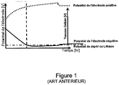
Figure 1 est un exemple de graphique représentant l'évolution du potentiel de l'électrode positive et du potentiel de l'électrode négative, en fonction de la durée de charge, selon l'art antérieur ; - la
Figure 2 est un organigramme d'un exemple de procédé selon un mode de réalisation de l'invention. - la
Figure 3 est un graphique de stratégie de charge d'une batterie Li-ion selon un exemple de l'invention, lorsque la température de charge est inférieure ou égale à une température seuil prédéterminée, et - la
Figure 4 est un exemple de véhicule automobile comprenant un ensemble de batterie de traction, selon un mode de réalisation.
- the
Figure 1 is an example of a graph showing the evolution of the potential of the positive electrode and the potential of the negative electrode, as a function of the charge duration, according to the prior art; - the
Figure 2 is a flowchart of an exemplary method according to one embodiment of the invention. - the
Figure 3 is a load strategy graph of a Li-ion battery according to an example of the invention, when the charging temperature is less than or equal to a predetermined threshold temperature, and - the
Figure 4 is an example of a motor vehicle comprising a traction battery assembly, according to one embodiment.
Selon la stratégie de charge de la
Selon la
Au cours d'une étape 102, on détermine une valeur de température seuil (TTHR) ici estimée en fonction du vieillissement de la batterie (f(SOHE)) 102. Par exemple, TTHR peut être égale à 15°C.During a
La tension seuil est également ici estimée en fonction de l'état de vieillissement de la batterie (f2(SOHE)) 102'.The threshold voltage is also here estimated as a function of the state of aging of the battery (f 2 (SOHE)) 102 '.
La deuxième étape (étape b)) 103 est, d'une part, la comparaison de cette valeur de température mesurée (T), selon 101, avec la température seuil (TTHR) et la comparaison de la tension de coupure (Vcut-off) avec la tension seuil (VTHR).The second step (step b) 103 is, on the one hand, the comparison of this measured temperature value (T), according to 101, with the threshold temperature (T THR ) and the comparison of the cutoff voltage (V cut -off ) with the threshold voltage (V THR ).
Lorsque cette température mesurée (T) est inférieure à TTHR, et lorsque Vcut-off est supérieure à VTHR, alors le système BMS génère un signal de commande de charge de la batterie selon la voie multi-étapes de l'invention (étape 104).When this measured temperature (T) is lower than T THR , and when V cut-off is greater than V THR , then the BMS system generates a charge control signal of the battery according to the multi-step channel of the invention ( step 104).
En revanche, si l'une et/ou l'autre de ces conditions n'est pas respectée, le système BMS génère, au cours d'une étape 104', un signal de commande 104' de charge CP-CV (S :=SCP-CV).On the other hand, if one and / or the other of these conditions is not respected, the system BMS generates, during a step 104 ', a control signal 104' of load CP-CV (S: = S CP-CV ).
Le signal de commande S est ensuite transmis vers un chargeur de la batterie Lithium-ion au cours d'une étape 105. La stratégie de charge est donc fonction des paramètres ci-dessus.The control signal S is then transmitted to a charger of the lithium-ion battery during a
Le procédé comporte également une étape d'attente (τ) entre l'exécution de deux boucles, c'est-à-dire de la mise en oeuvre des étape 101, 102, 102', 103, 104, 104' et 105.The method also comprises a waiting step (τ) between the execution of two loops, that is to say the implementation of the
Les
Plus précisément, la
La
Selon un exemple de l'invention, le potentiel de l'électrode se trouve inférieur à celui du dépôt de lithium que pendant un relativement bref instant, ici de 10 s, à chaque palier de décroissance de la puissance, ce qui, d'une part, peut éviter le dépôt de lithium métal en quantité critiques, et, d'autre part, peut augmenter ainsi la durabilité de la batterie tout en optimisant le temps de charge sans dégradation de la batterie notamment par des sur-tensions.According to an example of the invention, the potential of the electrode is lower than that of lithium deposition for a relatively short time, in this case by 10 s, at each decay of the power, which, of a on the other hand, can also increase the durability of the battery while optimizing the charging time without degradation of the battery including over-voltages.
En référence à la
La batterie 12 peut par exemple être une batterie lithium ion.The
Le chargeur peut par exemple être une borne de charge rapide fournissant un courant continu à l'ensemble de batterie 11 du véhicule 10.The charger can for example be a fast charging terminal supplying a direct current to the
L'ensemble de batterie 11 peut intégrer un dispositif de gestion de la charge 13, par exemple un système de contrôle de batterie de type BMS, lequel système comporte un processeur (non représenté) exécutant un programme comprenant des instructions pour adapter et/ou modifier la stratégie de charge à intervalles réguliers, en fonction de l'évolution au cours du temps de charge de la température de la batterie et de la tension de coupure. Un exemple de stratégie de charge est donné à la
Le dispositif de gestion de la charge 13 comporte des moyens de réception d'une valeur de température de la batterie et de la tension de coupure (non représentés), par exemple une broche d'entrée en communication électrique avec des capteurs (non représentés) du véhicule automobile 10.The
Le dispositif 13 comporte des moyens de traitement (non représentés), agencés pour comparer, d'une part, la valeur de température mesurée avec une valeur de température seuil et, d'autre part, de la tension de coupure avec une tension seuil, lesquels sont un coeur d'un processeur, et des moyens de transmission du signal (non représentés) vers un chargeur, lesquels sont une broche de sortie.The
Claims (11)
- Method for managing the charging of a lithium-ion battery, comprising the steps of:a) receiving (101) a measured value of the battery temperature;b) comparing (103) the measured value received in the step a) with a predetermined threshold temperature value;c) generating (104, 104') a charging control signal for said battery, the control signal being generated such that, when the measured temperature value is less than or equal to the threshold temperature value, the charging power, the charging voltage or the charging current decreases in steps, the transition from one level to the next being initiated when a determined voltage value at the terminals of the battery is reached, andd) transmitting (105) the control signal to a charger.
- Method according to Claim 1, in which, when the measured temperature value is less than or equal to the threshold temperature value, the charging power decreases in steps to levels lying within the range of values from 5 kW to 10 kW for charging powers greater than a determined power threshold, and in steps to levels lying within the range of values from 1 kW to 1.5 kW for charging powers less than this determined power threshold.
- Method according to Claim 1 or 2, in which, the measured temperature value is less than or equal to the threshold temperature value, a power level is maintained for a duration of between 10 s and 25 min.
- Method according to one of Claims 1 to 3, in which the steps a), b), c) and d) are regularly repeated during a same charge.
- Method according to one of Claims 1 to 3, in which the steps a) and b) are performed just once, at the start of charging.
- Method according to one of Claims 1 to 5, further comprising a step of determining the threshold temperature value, as a function of the state of aging of the battery (102).
- Method according to one of Claims 1 to 6, in which, when the temperature of the battery currently being charged is greater than the threshold temperature value, the charging control signal is generated so as to order a fast charging phase with rapidly increasing voltage followed by a phase of absorption with decreasing current regulated to a predetermined voltage value, for example a cutoff voltage.
- Method according to one of Claims 1 to 7, further comprising a step of reception of a measured value of the charging voltage and a step of comparison of the measured charging voltage value received with a determined threshold voltage value at the terminals of the battery, in which the control signal is generated in decreasing steps when the measured temperature value is less than or equal to the threshold temperature value or when the charging voltage is greater than a threshold voltage value.
- Computer program comprising instructions for performing the steps of the method according to one of Claims 1 to 8, when these instructions are executed by a processor.
- Device for managing the charging of a lithium-ion battery (13), comprising:- means for receiving a measured value of the battery temperature, from a temperature sensor;- processing means arranged to compare the measured value with a predetermined threshold temperature value, and to generate a charge control signal for said battery, in which the processing means are arranged so that, when the measured temperature value is less than or equal to the threshold temperature value, the control signal is generated in such a way that the charging power, the charging voltage or the charging current decreases in steps, the transition from one level to the next being initiated when a determined voltage value at the terminals of the battery is reached; and- transmission means for transmitting the control signal to a charger.
- Motor vehicle incorporating a lithium-ion battery (12) and a charging device (13) according to Claim 10.
Applications Claiming Priority (2)
| Application Number | Priority Date | Filing Date | Title |
|---|---|---|---|
| FR1352033A FR3003100B1 (en) | 2013-03-07 | 2013-03-07 | BATTERY CHARGE MANAGEMENT |
| PCT/FR2014/050511 WO2014135807A2 (en) | 2013-03-07 | 2014-03-06 | Managing the charging of a battery |
Publications (2)
| Publication Number | Publication Date |
|---|---|
| EP2965399A2 EP2965399A2 (en) | 2016-01-13 |
| EP2965399B1 true EP2965399B1 (en) | 2019-09-11 |
Family
ID=48613854
Family Applications (1)
| Application Number | Title | Priority Date | Filing Date |
|---|---|---|---|
| EP14713541.2A Active EP2965399B1 (en) | 2013-03-07 | 2014-03-06 | Management of battery charging |
Country Status (4)
| Country | Link |
|---|---|
| EP (1) | EP2965399B1 (en) |
| KR (1) | KR102024282B1 (en) |
| FR (1) | FR3003100B1 (en) |
| WO (1) | WO2014135807A2 (en) |
Cited By (1)
| Publication number | Priority date | Publication date | Assignee | Title |
|---|---|---|---|---|
| US12015290B2 (en) | 2020-10-30 | 2024-06-18 | Techtronic Cordless Gp | Battery pack with temperature limited current |
Families Citing this family (1)
| Publication number | Priority date | Publication date | Assignee | Title |
|---|---|---|---|---|
| US11367910B2 (en) | 2018-04-16 | 2022-06-21 | Ec Power, Llc | Systems and method of battery charging assisted by heating |
Family Cites Families (5)
| Publication number | Priority date | Publication date | Assignee | Title |
|---|---|---|---|---|
| US7737665B2 (en) * | 2005-06-10 | 2010-06-15 | Agere Systems Inc. | Multi-threshold charging of a rechargeable battery |
| US8624560B2 (en) * | 2008-04-11 | 2014-01-07 | Apple Inc. | Controlling battery charging based on current, voltage and temperature |
| NL2004503C2 (en) | 2010-04-02 | 2011-10-04 | Epyon B V | Method and device for charging a battery and battery charger. |
| JP5782803B2 (en) * | 2010-06-03 | 2015-09-24 | 日産自動車株式会社 | Battery charging device and battery charging method |
| JP5304844B2 (en) * | 2011-05-24 | 2013-10-02 | トヨタ自動車株式会社 | Battery charge control device |
-
2013
- 2013-03-07 FR FR1352033A patent/FR3003100B1/en not_active Expired - Fee Related
-
2014
- 2014-03-06 WO PCT/FR2014/050511 patent/WO2014135807A2/en active Application Filing
- 2014-03-06 EP EP14713541.2A patent/EP2965399B1/en active Active
- 2014-03-06 KR KR1020157027740A patent/KR102024282B1/en active IP Right Grant
Non-Patent Citations (1)
| Title |
|---|
| None * |
Cited By (1)
| Publication number | Priority date | Publication date | Assignee | Title |
|---|---|---|---|---|
| US12015290B2 (en) | 2020-10-30 | 2024-06-18 | Techtronic Cordless Gp | Battery pack with temperature limited current |
Also Published As
| Publication number | Publication date |
|---|---|
| FR3003100A1 (en) | 2014-09-12 |
| KR20150122800A (en) | 2015-11-02 |
| WO2014135807A2 (en) | 2014-09-12 |
| FR3003100B1 (en) | 2015-02-27 |
| KR102024282B1 (en) | 2019-09-23 |
| WO2014135807A3 (en) | 2014-11-27 |
| EP2965399A2 (en) | 2016-01-13 |
Similar Documents
| Publication | Publication Date | Title |
|---|---|---|
| EP2957018B1 (en) | Managing the charging of a battery | |
| EP3191337B1 (en) | Method for managing the operating range of a battery | |
| EP3237258B1 (en) | Method for energy management of a rechargeable traction battery of a hybrid vehicle | |
| EP2774246B1 (en) | Method and system for managing the electric charges of battery cells | |
| FR3065292B1 (en) | METHOD OF MANAGING A BATTERY BASED ON ITS HEALTH CONDITION | |
| EP2774210B1 (en) | Method for managing the operation of a hybrid system | |
| EP2721713B1 (en) | Method for powering an electrical accessory of a motor vehicle comprising an electric battery to which said accessory is connected | |
| WO2020074397A1 (en) | Method and device for controlling the level of charge of a traction battery of an electric vehicle | |
| EP2965399B1 (en) | Management of battery charging | |
| EP2945817B1 (en) | Management of the charge of a battery | |
| WO2021130068A1 (en) | Method for identifying the start of the acceleration of the degradation of the state of health of a pack of rechargeable batteries | |
| EP4101047B1 (en) | Method of pulse charging with variable amplitude step | |
| EP3235048B1 (en) | Pulsed charging method for lithium ion batteries and apparatus therefor | |
| WO2015101731A1 (en) | Method for estimating the ability of a battery to supply a predetermined power profile | |
| FR2982206A1 (en) | DEVICE AND METHOD FOR MANAGING A BATTERY FOR ITS NON-USE DURING A SELECTED DURATION | |
| FR3109449A1 (en) | Method for calibrating a charging current of a battery of an electric motor vehicle | |
| WO2024180285A1 (en) | Pulsed fast-charging method with regulated-amplitude voltage increments | |
| EP4382930A1 (en) | Method for managing a battery | |
| WO2023227722A1 (en) | Method for detecting a risk of failure through imbalance of a device for storing energy comprising a set of stages of electrochemical cells | |
| FR3122786A1 (en) | METHOD FOR MANAGING A CHARGE LEVEL OF A LOW-VOLTAGE ENERGY STORAGE | |
| WO2023001830A1 (en) | Vehicle comprising a rechargeable battery and means for determining a maximum acceptable power for the battery during a charging phase | |
| WO2024008715A1 (en) | Method for detecting a risk of malfunction through imbalance of a device for storing energy comprising a set of levels of electrochemical cells | |
| WO2008081133A2 (en) | Method for the management of energy flows in an electric power supply device |
Legal Events
| Date | Code | Title | Description |
|---|---|---|---|
| PUAI | Public reference made under article 153(3) epc to a published international application that has entered the european phase |
Free format text: ORIGINAL CODE: 0009012 |
|
| 17P | Request for examination filed |
Effective date: 20150902 |
|
| AK | Designated contracting states |
Kind code of ref document: A2 Designated state(s): AL AT BE BG CH CY CZ DE DK EE ES FI FR GB GR HR HU IE IS IT LI LT LU LV MC MK MT NL NO PL PT RO RS SE SI SK SM TR |
|
| AX | Request for extension of the european patent |
Extension state: BA ME |
|
| DAX | Request for extension of the european patent (deleted) | ||
| GRAP | Despatch of communication of intention to grant a patent |
Free format text: ORIGINAL CODE: EPIDOSNIGR1 |
|
| STAA | Information on the status of an ep patent application or granted ep patent |
Free format text: STATUS: GRANT OF PATENT IS INTENDED |
|
| RIC1 | Information provided on ipc code assigned before grant |
Ipc: H01M 10/052 20100101ALN20181009BHEP Ipc: H01M 10/44 20060101ALI20181009BHEP Ipc: H02J 7/00 20060101AFI20181009BHEP |
|
| INTG | Intention to grant announced |
Effective date: 20181025 |
|
| GRAS | Grant fee paid |
Free format text: ORIGINAL CODE: EPIDOSNIGR3 |
|
| GRAJ | Information related to disapproval of communication of intention to grant by the applicant or resumption of examination proceedings by the epo deleted |
Free format text: ORIGINAL CODE: EPIDOSDIGR1 |
|
| GRAL | Information related to payment of fee for publishing/printing deleted |
Free format text: ORIGINAL CODE: EPIDOSDIGR3 |
|
| GRAP | Despatch of communication of intention to grant a patent |
Free format text: ORIGINAL CODE: EPIDOSNIGR1 |
|
| RIC1 | Information provided on ipc code assigned before grant |
Ipc: H01M 10/44 20060101ALI20190304BHEP Ipc: H01M 10/052 20100101ALN20190304BHEP Ipc: H02J 7/00 20060101AFI20190304BHEP |
|
| RIC1 | Information provided on ipc code assigned before grant |
Ipc: H01M 10/052 20100101ALN20190318BHEP Ipc: H02J 7/00 20060101AFI20190318BHEP Ipc: H01M 10/44 20060101ALI20190318BHEP |
|
| RIN1 | Information on inventor provided before grant (corrected) |
Inventor name: SAINT-MARCOUX, ANTOINE Inventor name: GIRAUD, MARC-HENRI Inventor name: DELOBEL, BRUNO |
|
| INTG | Intention to grant announced |
Effective date: 20190408 |
|
| GRAA | (expected) grant |
Free format text: ORIGINAL CODE: 0009210 |
|
| STAA | Information on the status of an ep patent application or granted ep patent |
Free format text: STATUS: THE PATENT HAS BEEN GRANTED |
|
| AK | Designated contracting states |
Kind code of ref document: B1 Designated state(s): AL AT BE BG CH CY CZ DE DK EE ES FI FR GB GR HR HU IE IS IT LI LT LU LV MC MK MT NL NO PL PT RO RS SE SI SK SM TR |
|
| REG | Reference to a national code |
Ref country code: GB Ref legal event code: FG4D Free format text: NOT ENGLISH |
|
| REG | Reference to a national code |
Ref country code: CH Ref legal event code: EP |
|
| REG | Reference to a national code |
Ref country code: AT Ref legal event code: REF Ref document number: 1179745 Country of ref document: AT Kind code of ref document: T Effective date: 20190915 |
|
| REG | Reference to a national code |
Ref country code: DE Ref legal event code: R096 Ref document number: 602014053380 Country of ref document: DE Ref country code: IE Ref legal event code: FG4D Free format text: LANGUAGE OF EP DOCUMENT: FRENCH |
|
| REG | Reference to a national code |
Ref country code: NL Ref legal event code: MP Effective date: 20190911 |
|
| REG | Reference to a national code |
Ref country code: LT Ref legal event code: MG4D |
|
| PG25 | Lapsed in a contracting state [announced via postgrant information from national office to epo] |
Ref country code: LT Free format text: LAPSE BECAUSE OF FAILURE TO SUBMIT A TRANSLATION OF THE DESCRIPTION OR TO PAY THE FEE WITHIN THE PRESCRIBED TIME-LIMIT Effective date: 20190911 Ref country code: FI Free format text: LAPSE BECAUSE OF FAILURE TO SUBMIT A TRANSLATION OF THE DESCRIPTION OR TO PAY THE FEE WITHIN THE PRESCRIBED TIME-LIMIT Effective date: 20190911 Ref country code: NO Free format text: LAPSE BECAUSE OF FAILURE TO SUBMIT A TRANSLATION OF THE DESCRIPTION OR TO PAY THE FEE WITHIN THE PRESCRIBED TIME-LIMIT Effective date: 20191211 Ref country code: BG Free format text: LAPSE BECAUSE OF FAILURE TO SUBMIT A TRANSLATION OF THE DESCRIPTION OR TO PAY THE FEE WITHIN THE PRESCRIBED TIME-LIMIT Effective date: 20191211 Ref country code: SE Free format text: LAPSE BECAUSE OF FAILURE TO SUBMIT A TRANSLATION OF THE DESCRIPTION OR TO PAY THE FEE WITHIN THE PRESCRIBED TIME-LIMIT Effective date: 20190911 Ref country code: HR Free format text: LAPSE BECAUSE OF FAILURE TO SUBMIT A TRANSLATION OF THE DESCRIPTION OR TO PAY THE FEE WITHIN THE PRESCRIBED TIME-LIMIT Effective date: 20190911 |
|
| PG25 | Lapsed in a contracting state [announced via postgrant information from national office to epo] |
Ref country code: LV Free format text: LAPSE BECAUSE OF FAILURE TO SUBMIT A TRANSLATION OF THE DESCRIPTION OR TO PAY THE FEE WITHIN THE PRESCRIBED TIME-LIMIT Effective date: 20190911 Ref country code: GR Free format text: LAPSE BECAUSE OF FAILURE TO SUBMIT A TRANSLATION OF THE DESCRIPTION OR TO PAY THE FEE WITHIN THE PRESCRIBED TIME-LIMIT Effective date: 20191212 Ref country code: RS Free format text: LAPSE BECAUSE OF FAILURE TO SUBMIT A TRANSLATION OF THE DESCRIPTION OR TO PAY THE FEE WITHIN THE PRESCRIBED TIME-LIMIT Effective date: 20190911 Ref country code: AL Free format text: LAPSE BECAUSE OF FAILURE TO SUBMIT A TRANSLATION OF THE DESCRIPTION OR TO PAY THE FEE WITHIN THE PRESCRIBED TIME-LIMIT Effective date: 20190911 Ref country code: ES Free format text: LAPSE BECAUSE OF FAILURE TO SUBMIT A TRANSLATION OF THE DESCRIPTION OR TO PAY THE FEE WITHIN THE PRESCRIBED TIME-LIMIT Effective date: 20190911 |
|
| REG | Reference to a national code |
Ref country code: AT Ref legal event code: MK05 Ref document number: 1179745 Country of ref document: AT Kind code of ref document: T Effective date: 20190911 |
|
| PG25 | Lapsed in a contracting state [announced via postgrant information from national office to epo] |
Ref country code: PL Free format text: LAPSE BECAUSE OF FAILURE TO SUBMIT A TRANSLATION OF THE DESCRIPTION OR TO PAY THE FEE WITHIN THE PRESCRIBED TIME-LIMIT Effective date: 20190911 Ref country code: EE Free format text: LAPSE BECAUSE OF FAILURE TO SUBMIT A TRANSLATION OF THE DESCRIPTION OR TO PAY THE FEE WITHIN THE PRESCRIBED TIME-LIMIT Effective date: 20190911 Ref country code: NL Free format text: LAPSE BECAUSE OF FAILURE TO SUBMIT A TRANSLATION OF THE DESCRIPTION OR TO PAY THE FEE WITHIN THE PRESCRIBED TIME-LIMIT Effective date: 20190911 Ref country code: AT Free format text: LAPSE BECAUSE OF FAILURE TO SUBMIT A TRANSLATION OF THE DESCRIPTION OR TO PAY THE FEE WITHIN THE PRESCRIBED TIME-LIMIT Effective date: 20190911 Ref country code: IT Free format text: LAPSE BECAUSE OF FAILURE TO SUBMIT A TRANSLATION OF THE DESCRIPTION OR TO PAY THE FEE WITHIN THE PRESCRIBED TIME-LIMIT Effective date: 20190911 Ref country code: PT Free format text: LAPSE BECAUSE OF FAILURE TO SUBMIT A TRANSLATION OF THE DESCRIPTION OR TO PAY THE FEE WITHIN THE PRESCRIBED TIME-LIMIT Effective date: 20200113 Ref country code: RO Free format text: LAPSE BECAUSE OF FAILURE TO SUBMIT A TRANSLATION OF THE DESCRIPTION OR TO PAY THE FEE WITHIN THE PRESCRIBED TIME-LIMIT Effective date: 20190911 |
|
| PG25 | Lapsed in a contracting state [announced via postgrant information from national office to epo] |
Ref country code: SM Free format text: LAPSE BECAUSE OF FAILURE TO SUBMIT A TRANSLATION OF THE DESCRIPTION OR TO PAY THE FEE WITHIN THE PRESCRIBED TIME-LIMIT Effective date: 20190911 Ref country code: CZ Free format text: LAPSE BECAUSE OF FAILURE TO SUBMIT A TRANSLATION OF THE DESCRIPTION OR TO PAY THE FEE WITHIN THE PRESCRIBED TIME-LIMIT Effective date: 20190911 Ref country code: IS Free format text: LAPSE BECAUSE OF FAILURE TO SUBMIT A TRANSLATION OF THE DESCRIPTION OR TO PAY THE FEE WITHIN THE PRESCRIBED TIME-LIMIT Effective date: 20200224 Ref country code: SK Free format text: LAPSE BECAUSE OF FAILURE TO SUBMIT A TRANSLATION OF THE DESCRIPTION OR TO PAY THE FEE WITHIN THE PRESCRIBED TIME-LIMIT Effective date: 20190911 |
|
| REG | Reference to a national code |
Ref country code: DE Ref legal event code: R097 Ref document number: 602014053380 Country of ref document: DE |
|
| PLBE | No opposition filed within time limit |
Free format text: ORIGINAL CODE: 0009261 |
|
| STAA | Information on the status of an ep patent application or granted ep patent |
Free format text: STATUS: NO OPPOSITION FILED WITHIN TIME LIMIT |
|
| PG2D | Information on lapse in contracting state deleted |
Ref country code: IS |
|
| PG25 | Lapsed in a contracting state [announced via postgrant information from national office to epo] |
Ref country code: DK Free format text: LAPSE BECAUSE OF FAILURE TO SUBMIT A TRANSLATION OF THE DESCRIPTION OR TO PAY THE FEE WITHIN THE PRESCRIBED TIME-LIMIT Effective date: 20190911 Ref country code: IS Free format text: LAPSE BECAUSE OF FAILURE TO SUBMIT A TRANSLATION OF THE DESCRIPTION OR TO PAY THE FEE WITHIN THE PRESCRIBED TIME-LIMIT Effective date: 20200112 |
|
| 26N | No opposition filed |
Effective date: 20200615 |
|
| PG25 | Lapsed in a contracting state [announced via postgrant information from national office to epo] |
Ref country code: SI Free format text: LAPSE BECAUSE OF FAILURE TO SUBMIT A TRANSLATION OF THE DESCRIPTION OR TO PAY THE FEE WITHIN THE PRESCRIBED TIME-LIMIT Effective date: 20190911 |
|
| PG25 | Lapsed in a contracting state [announced via postgrant information from national office to epo] |
Ref country code: MC Free format text: LAPSE BECAUSE OF FAILURE TO SUBMIT A TRANSLATION OF THE DESCRIPTION OR TO PAY THE FEE WITHIN THE PRESCRIBED TIME-LIMIT Effective date: 20190911 |
|
| REG | Reference to a national code |
Ref country code: CH Ref legal event code: PL |
|
| REG | Reference to a national code |
Ref country code: BE Ref legal event code: MM Effective date: 20200331 |
|
| PG25 | Lapsed in a contracting state [announced via postgrant information from national office to epo] |
Ref country code: LU Free format text: LAPSE BECAUSE OF NON-PAYMENT OF DUE FEES Effective date: 20200306 |
|
| PG25 | Lapsed in a contracting state [announced via postgrant information from national office to epo] |
Ref country code: LI Free format text: LAPSE BECAUSE OF NON-PAYMENT OF DUE FEES Effective date: 20200331 Ref country code: CH Free format text: LAPSE BECAUSE OF NON-PAYMENT OF DUE FEES Effective date: 20200331 Ref country code: IE Free format text: LAPSE BECAUSE OF NON-PAYMENT OF DUE FEES Effective date: 20200306 |
|
| PG25 | Lapsed in a contracting state [announced via postgrant information from national office to epo] |
Ref country code: BE Free format text: LAPSE BECAUSE OF NON-PAYMENT OF DUE FEES Effective date: 20200331 |
|
| PG25 | Lapsed in a contracting state [announced via postgrant information from national office to epo] |
Ref country code: TR Free format text: LAPSE BECAUSE OF FAILURE TO SUBMIT A TRANSLATION OF THE DESCRIPTION OR TO PAY THE FEE WITHIN THE PRESCRIBED TIME-LIMIT Effective date: 20190911 Ref country code: MT Free format text: LAPSE BECAUSE OF FAILURE TO SUBMIT A TRANSLATION OF THE DESCRIPTION OR TO PAY THE FEE WITHIN THE PRESCRIBED TIME-LIMIT Effective date: 20190911 Ref country code: CY Free format text: LAPSE BECAUSE OF FAILURE TO SUBMIT A TRANSLATION OF THE DESCRIPTION OR TO PAY THE FEE WITHIN THE PRESCRIBED TIME-LIMIT Effective date: 20190911 |
|
| PG25 | Lapsed in a contracting state [announced via postgrant information from national office to epo] |
Ref country code: MK Free format text: LAPSE BECAUSE OF FAILURE TO SUBMIT A TRANSLATION OF THE DESCRIPTION OR TO PAY THE FEE WITHIN THE PRESCRIBED TIME-LIMIT Effective date: 20190911 |
|
| PGFP | Annual fee paid to national office [announced via postgrant information from national office to epo] |
Ref country code: FR Payment date: 20230324 Year of fee payment: 10 |
|
| PGFP | Annual fee paid to national office [announced via postgrant information from national office to epo] |
Ref country code: GB Payment date: 20230322 Year of fee payment: 10 Ref country code: DE Payment date: 20230321 Year of fee payment: 10 |
|
| P01 | Opt-out of the competence of the unified patent court (upc) registered |
Effective date: 20230608 |
|
| REG | Reference to a national code |
Ref country code: DE Ref legal event code: R081 Ref document number: 602014053380 Country of ref document: DE Owner name: AMPERE S.A.S., FR Free format text: FORMER OWNER: RENAULT S.A.S., BOULOGNE-BILLANCOURT, FR |