EP2965343B1 - Improved lock component corrections - Google Patents
Improved lock component corrections Download PDFInfo
- Publication number
- EP2965343B1 EP2965343B1 EP14710348.5A EP14710348A EP2965343B1 EP 2965343 B1 EP2965343 B1 EP 2965343B1 EP 14710348 A EP14710348 A EP 14710348A EP 2965343 B1 EP2965343 B1 EP 2965343B1
- Authority
- EP
- European Patent Office
- Prior art keywords
- time
- mass
- ions
- ion mobility
- flight
- Prior art date
- Legal status (The legal status is an assumption and is not a legal conclusion. Google has not performed a legal analysis and makes no representation as to the accuracy of the status listed.)
- Active
Links
- 238000012937 correction Methods 0.000 title description 13
- 150000002500 ions Chemical class 0.000 claims description 172
- 238000000034 method Methods 0.000 claims description 24
- 238000011088 calibration curve Methods 0.000 claims description 10
- 238000004949 mass spectrometry Methods 0.000 claims description 6
- 238000013467 fragmentation Methods 0.000 description 22
- 238000006062 fragmentation reaction Methods 0.000 description 22
- 238000013459 approach Methods 0.000 description 20
- 238000006243 chemical reaction Methods 0.000 description 13
- 238000000926 separation method Methods 0.000 description 10
- 238000010494 dissociation reaction Methods 0.000 description 8
- 230000005593 dissociations Effects 0.000 description 8
- 230000001133 acceleration Effects 0.000 description 7
- 238000005040 ion trap Methods 0.000 description 7
- 238000005259 measurement Methods 0.000 description 7
- 230000009897 systematic effect Effects 0.000 description 7
- 238000003795 desorption Methods 0.000 description 6
- 230000000694 effects Effects 0.000 description 6
- 230000003595 spectral effect Effects 0.000 description 5
- 238000004587 chromatography analysis Methods 0.000 description 3
- 238000001077 electron transfer detection Methods 0.000 description 3
- 230000005686 electrostatic field Effects 0.000 description 3
- 239000011159 matrix material Substances 0.000 description 3
- 238000004252 FT/ICR mass spectrometry Methods 0.000 description 2
- 239000012491 analyte Substances 0.000 description 2
- 238000004458 analytical method Methods 0.000 description 2
- 238000002045 capillary electrochromatography Methods 0.000 description 2
- 239000000919 ceramic Substances 0.000 description 2
- 150000001875 compounds Chemical class 0.000 description 2
- 238000000375 direct analysis in real time Methods 0.000 description 2
- 238000001211 electron capture detection Methods 0.000 description 2
- 238000010265 fast atom bombardment Methods 0.000 description 2
- 238000004992 fast atom bombardment mass spectroscopy Methods 0.000 description 2
- 239000012634 fragment Substances 0.000 description 2
- 238000009616 inductively coupled plasma Methods 0.000 description 2
- 238000010884 ion-beam technique Methods 0.000 description 2
- 230000005855 radiation Effects 0.000 description 2
- 238000001228 spectrum Methods 0.000 description 2
- 238000011144 upstream manufacturing Methods 0.000 description 2
- 102100022704 Amyloid-beta precursor protein Human genes 0.000 description 1
- 208000035699 Distal ileal obstruction syndrome Diseases 0.000 description 1
- 102000004190 Enzymes Human genes 0.000 description 1
- 108090000790 Enzymes Proteins 0.000 description 1
- 101000823051 Homo sapiens Amyloid-beta precursor protein Proteins 0.000 description 1
- XUIMIQQOPSSXEZ-UHFFFAOYSA-N Silicon Chemical compound [Si] XUIMIQQOPSSXEZ-UHFFFAOYSA-N 0.000 description 1
- 239000008186 active pharmaceutical agent Substances 0.000 description 1
- DZHSAHHDTRWUTF-SIQRNXPUSA-N amyloid-beta polypeptide 42 Chemical compound C([C@@H](C(=O)N[C@@H](C)C(=O)N[C@@H](CCC(O)=O)C(=O)N[C@@H](CC(O)=O)C(=O)N[C@H](C(=O)NCC(=O)N[C@@H](CO)C(=O)N[C@@H](CC(N)=O)C(=O)N[C@@H](CCCCN)C(=O)NCC(=O)N[C@@H](C)C(=O)N[C@H](C(=O)N[C@@H]([C@@H](C)CC)C(=O)NCC(=O)N[C@@H](CC(C)C)C(=O)N[C@@H](CCSC)C(=O)N[C@@H](C(C)C)C(=O)NCC(=O)NCC(=O)N[C@@H](C(C)C)C(=O)N[C@@H](C(C)C)C(=O)N[C@@H]([C@@H](C)CC)C(=O)N[C@@H](C)C(O)=O)[C@@H](C)CC)C(C)C)NC(=O)[C@H](CC=1C=CC=CC=1)NC(=O)[C@@H](NC(=O)[C@H](CC(C)C)NC(=O)[C@H](CCCCN)NC(=O)[C@H](CCC(N)=O)NC(=O)[C@H](CC=1N=CNC=1)NC(=O)[C@H](CC=1N=CNC=1)NC(=O)[C@@H](NC(=O)[C@H](CCC(O)=O)NC(=O)[C@H](CC=1C=CC(O)=CC=1)NC(=O)CNC(=O)[C@H](CO)NC(=O)[C@H](CC(O)=O)NC(=O)[C@H](CC=1N=CNC=1)NC(=O)[C@H](CCCNC(N)=N)NC(=O)[C@H](CC=1C=CC=CC=1)NC(=O)[C@H](CCC(O)=O)NC(=O)[C@H](C)NC(=O)[C@@H](N)CC(O)=O)C(C)C)C(C)C)C1=CC=CC=C1 DZHSAHHDTRWUTF-SIQRNXPUSA-N 0.000 description 1
- 238000000065 atmospheric pressure chemical ionisation Methods 0.000 description 1
- 238000005251 capillar electrophoresis Methods 0.000 description 1
- 230000015556 catabolic process Effects 0.000 description 1
- 230000001413 cellular effect Effects 0.000 description 1
- 238000000451 chemical ionisation Methods 0.000 description 1
- 238000001360 collision-induced dissociation Methods 0.000 description 1
- 238000006731 degradation reaction Methods 0.000 description 1
- 238000000688 desorption electrospray ionisation Methods 0.000 description 1
- 238000000766 differential mobility spectroscopy Methods 0.000 description 1
- 238000012063 dual-affinity re-targeting Methods 0.000 description 1
- 230000005684 electric field Effects 0.000 description 1
- 238000000132 electrospray ionisation Methods 0.000 description 1
- 238000010828 elution Methods 0.000 description 1
- 238000001976 enzyme digestion Methods 0.000 description 1
- 238000004817 gas chromatography Methods 0.000 description 1
- 238000002347 injection Methods 0.000 description 1
- 239000007924 injection Substances 0.000 description 1
- 238000002955 isolation Methods 0.000 description 1
- 238000001698 laser desorption ionisation Methods 0.000 description 1
- 238000004811 liquid chromatography Methods 0.000 description 1
- 238000000816 matrix-assisted laser desorption--ionisation Methods 0.000 description 1
- PXHVJJICTQNCMI-RNFDNDRNSA-N nickel-63 Chemical compound [63Ni] PXHVJJICTQNCMI-RNFDNDRNSA-N 0.000 description 1
- 238000002413 orthogonal acceleration time of flight mass spectrometry Methods 0.000 description 1
- 238000004150 penning trap Methods 0.000 description 1
- 230000002285 radioactive effect Effects 0.000 description 1
- 238000005070 sampling Methods 0.000 description 1
- 229910052710 silicon Inorganic materials 0.000 description 1
- 239000010703 silicon Substances 0.000 description 1
- 239000002904 solvent Substances 0.000 description 1
- 239000000758 substrate Substances 0.000 description 1
- 238000004808 supercritical fluid chromatography Methods 0.000 description 1
- 238000010998 test method Methods 0.000 description 1
- 238000001269 time-of-flight mass spectrometry Methods 0.000 description 1
- 230000001960 triggered effect Effects 0.000 description 1
Images
Classifications
-
- H—ELECTRICITY
- H01—ELECTRIC ELEMENTS
- H01J—ELECTRIC DISCHARGE TUBES OR DISCHARGE LAMPS
- H01J49/00—Particle spectrometers or separator tubes
- H01J49/0009—Calibration of the apparatus
-
- H—ELECTRICITY
- H01—ELECTRIC ELEMENTS
- H01J—ELECTRIC DISCHARGE TUBES OR DISCHARGE LAMPS
- H01J49/00—Particle spectrometers or separator tubes
- H01J49/0027—Methods for using particle spectrometers
-
- H—ELECTRICITY
- H01—ELECTRIC ELEMENTS
- H01J—ELECTRIC DISCHARGE TUBES OR DISCHARGE LAMPS
- H01J49/00—Particle spectrometers or separator tubes
- H01J49/26—Mass spectrometers or separator tubes
- H01J49/34—Dynamic spectrometers
- H01J49/40—Time-of-flight spectrometers
Definitions
- the present invention relates to a method of mass spectrometry and a mass spectrometer.
- a known initial calibration routine involves utilising a calibration file in conjunction with a number of known compounds. Different known species of ions having different mass to charge ratios are mass analysed and the time of flight or mass to charge ratio of the different species of ions is determined. The correspondence between the measured time of flight or the mass to charge ratio of the known different species of ions and the theoretical mass to charge ratio of the ions as held in the calibration file is determined. A calibration curve is then fitted and adjusted to minimise the errors between the experimentally determined values and the theoretical values of the initial calibration compounds. In particular, a 5th order polynomial calibration curve may be fitted to the experimental data and the terms of the 5th order polynomial calibration curve may be adjusted so that the RMS error is as low as possible. The calibration curve is then used in subsequent mass analyses.
- the mass spectrometer may experience changing conditions which can potentially have a significant impact upon the measured time of flight (and hence determined mass to charge ratio) of ions by the Time of Flight mass analyser.
- a temperature change of 1°C can shift the measured time of flight and measured mass to charge ratio of all ions by approximately 40 ppm.
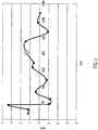
- Fig. 1 shows some of the residual calibration errors following an initial conventional calibration routine. It is apparent that the residual calibration errors may typically be a few ppm.
- GB-2494492 (Micromass ) discloses a method to single point internal lock-mobility correction.
- GB-2406966 discloses a method of correcting spectral skew in a mass spectrometer.
- US-6519542 discloses a method of testing an unknown sample with an analytical tool.
- J. V. OLSEN "Parts per Million Mass Accuracy on an Orbitrap Mass Spectrometer via Lock Mass Injection into a C-trap", MOLECULAR & CELLULAR PROTEOMICS, vol. 4, no. 12, 23 August 2005 (2005-08-23), pages 2010-2021 discloses a method for calibrating a mass spectrometer using theoretical mass to charge values for lock mass ions.
- the present invention is concerned with removing some sources of systematic error in lock component corrections thereby ultimately improving spectra accuracy.
- Improved lock component (i.e. mass or mobility) correction is a new mode of operation for existing instrument geometries and future novel instrument geometries.
- the present invention provides the capability to improve the accuracy of mass or mobility spectra data by accounting for instrument drift.
- Known approaches that attempt to compensate for drift suffer from the problem that they can introduce systematic accuracy errors.
- the preferred device preferably comprises at least one ion separation device such as an ion mobility separator ("IMS") or a mass spectrometer (“MS”) and a method of calibration.
- IMS ion mobility separator
- MS mass spectrometer
- a lock component such as a lockmass
- the method and apparatus according to the present invention may involve initially calibrating a mass spectrometer at a time T 0 .
- the mass spectrometer may already be calibrated and at time T 0 the mass spectrometer is recalibrated.
- the step of initially calibrating or recalibrating the mass spectrometer at the time T 0 preferably comprises performing a calibration routine to produce a calibration curve.
- the calibration curve preferably corresponds to a curve of best fit which relates the measured mass to charge ratio or time of flight of a plurality of known ions with the actual or known mass to charge ratio or time of flight of the plurality of known ions.
- the time of flight or mass to charge ratio M 0 of the one or more lockmass ions at time T 0 (which is preferably uncorrected or uncalibrated) preferably comprises a measured time of flight or mass to charge ratio of the one or more lockmass ions prior to the application of the calibration curve.
- the step of adjusting the determined time of flight or mass to charge ratio of the ions preferably further comprises adjusting an instrument or voltage setting of the mass spectrometer based upon the adjustment of the determined time of flight or mass to charge ratio of the ions.
- the time of flight or mass to charge ratio M 0 of the one or more lockmass ions at time T 0 is preferably uncorrected or uncalibrated.
- the control system is preferably further arranged and adapted to adjust an instrument or voltage setting of the mass spectrometer based upon the adjustment of the determined time of flight or mass to charge ratio of the ions.
- the ion mobility or differential ion mobility P 0 of the one or more first ions at time T 0 is preferably uncorrected or uncalibrated.
- the first ions preferably comprise lockmass ions.
- the first ions comprise ins have fixed or locked time of flight, mass to charge ratio, ion mobility, differential ion mobility or elution time.
- an ion mobility separator or differential ion mobility separator as claimed in claim 11.
- a mass spectrometer comprising an ion mobility separator or differential ion mobility separator as claimed in claim 12.
- the mass spectrometer may further comprise either:
- the mass spectrometer further comprises a device arranged and adapted to supply an AC or RF voltage to the electrodes.
- the AC or RF voltage preferably has an amplitude selected from the group consisting of: (i) ⁇ 50 V peak to peak; (ii) 50-100 V peak to peak; (iii) 100-150 V peak to peak; (iv) 150-200 V peak to peak; (v) 200-250 V peak to peak; (vi) 250-300 V peak to peak; (vii) 300-350 V peak to peak; (viii) 350-400 V peak to peak; (ix) 400-450 V peak to peak; (x) 450-500 V peak to peak; and (xi) > 500 V peak to peak.
- the AC or RF voltage preferably has a frequency selected from the group consisting of: (i) ⁇ 100 kHz; (ii) 100-200 kHz; (iii) 200-300 kHz; (iv) 300-400 kHz; (v) 400-500 kHz; (vi) 0.5-1.0 MHz; (vii) 1.0-1.5 MHz; (viii) 1.5-2.0 MHz; (ix) 2.0-2.5 MHz; (x) 2.5-3.0 MHz; (xi) 3.0-3.5 MHz; (xii) 3.5-4.0 MHz; (xiii) 4.0-4.5 MHz; (xiv) 4.5-5.0 MHz; (xv) 5.0-5.5 MHz; (xvi) 5.5-6.0 MHz; (xvii) 6.0-6.5 MHz; (xviii) 6.5-7.0 MHz; (xix) 7.0-7.5 MHz; (xx) 7.5-8.0 MHz; (xxi) 8.0-8.5 MHz; (xxii) 8.5
- the mass spectrometer may also comprise a chromatography or other separation device upstream of an ion source.
- the chromatography separation device comprises a liquid chromatography or gas chromatography device.
- the separation device may comprise: (i) a Capillary Electrophoresis (“CE”) separation device; (ii) a Capillary Electrochromatography (“CEC”) separation device; (iii) a substantially rigid ceramic-based multilayer microfluidic substrate (“ceramic tile”) separation device; or (iv) a supercritical fluid chromatography separation device.
- the ion guide is preferably maintained at a pressure selected from the group consisting of: (i) ⁇ 0.0001 mbar; (ii) 0.0001-0.001 mbar; (iii) 0.001-0.01 mbar; (iv) 0.01-0.1 mbar; (v) 0.1-1 mbar; (vi) 1-10 mbar; (vii) 10-100 mbar; (viii) 100-1000 mbar; and (ix) > 1000 mbar.
- Lockmass corrections have been employed to compensate for mass scale drift due to various factors such as temperature related length changes and the variation of voltages in orthogonal acceleration Time of Flight mass spectrometry.
- lockmasses may be introduced in isolation via a lockspray or alternatively the lockmasses may be introduced so that they are mixed with analyte ions via an internal lockmass approach.
- the measured mass to charge ratio values of the lockmass or lockmasses are then compared with the theoretical mass to charge values of the known lockmass components. The differences between the measured values and the theoretical values are then used to calculate a global adjustment or shift in mass to charge ratio which is then applied to all mass spectral data to correct for the instrument drift.
- Fig. 1 illustrates one of the drawbacks of the known approach.
- Fig. 1 shows some of the calibration residuals after initially calibrating a conventional orthogonal acceleration Time of Flight mass analyser. In this data the root mean square of the residuals is approximately 1.3 ppm. In practice this means that the absolute measurement of a particular mass to charge ratio could be up to 3-4 ppm in error immediately subsequent to initial calibration. For example, ions which are measured and which have a mass to charge ratio around 800 will be determined to have a mass to charge ratio which is in fact 1.5 ppm away from the correct value.
- the present invention seeks to alleviate some of these problems.
- the nominated lockmass or lockmasses are measured at the same time (or close to the same time) as when an initial calibration routine is executed.
- the measured lockmass values are then stored or recorded allowing future lockmass measurements to be compared with the actual lockmass measurement at the time of calibration rather than the theoretical lockmass value.
- the remainder of the lockmass correction routine completes as normal following this step.
- the advantage of the approach according to the preferred embodiment is that the act of lock mass correction now solely compensates for instrument drift rather than seeking to correct for instrument drift whilst potentially inadvertently introducing a systematic calibration error.
- the data would be corrected back to the theoretical value + 1.5 ppm according to the preferred embodiment thereby removing a 1.5 ppm system error which would otherwise be introduced by the conventional lockmass correction method.
- the approach according to the preferred embodiment also has the added advantage that the actual or theoretical mass to charge ratio of the lockmass ions does not actually need to be known. As long as the nominated lockmasses are consistent, the act of measuring them at the point of initial calibration removes the need to know their accurate mass.
- the approach according to the preferred embodiment and as described above can be applied to all types of mass spectrometers including orthogonal acceleration Time of Flight mass analysers, Fourier Transform Mass Spectrometers (FT-ICR), electrostatic mass analysers arranged to generate an electrostatic field having a quadro-logarithmic potential distribution, non Fourier Transform ion traps, quadrupole based systems and magnetic sector based instruments.
- FT-ICR Fourier Transform Mass Spectrometers
- electrostatic mass analysers arranged to generate an electrostatic field having a quadro-logarithmic potential distribution
- non Fourier Transform ion traps quadrupole based systems
- magnetic sector based instruments magnetic sector based instruments.
- the approach can be applied to other analytical instruments such as ion mobility spectrometers, Field Asymmetric Ion Mobility Spectrometers ("FAIMS”), Differential Mobility Spectrometers (“DMS”), chromatography etc.
- FIMS Field Asymmetric Ion Mobility Spectrometers
- DMS Differential Mobility Spectrometers
- chromatography etc.
- more than one lock component may be used.
- the measurement of the lock component or components may be made in multiple dimensions of separation such as mass to charge ratio and ion mobility and that the approach can be applied to the multiple dimensional data.
- one or more of the lock components may not be a ion signal and may be an electronic signal such a pulse triggered from a pusher voltage for calibration time offset correction in Time of Flight mass spectrometry.
- the approach according to the preferred embodiment can compensate for instrument changes between the calibration and lock mass channels such as lens settings, mass range settings (RF and pusher period), travelling wave setting as well as 'mode changes' such as IMS, Time of Flight, Enhanced Duty Cycle ("EDC”), High Duty Cycle (“HDC”) or combinations of modes.
- instrument changes between the calibration and lock mass channels such as lens settings, mass range settings (RF and pusher period), travelling wave setting as well as 'mode changes' such as IMS, Time of Flight, Enhanced Duty Cycle (“EDC”), High Duty Cycle (“HDC”) or combinations of modes.
- the preferred approach can be applied in the acquisition domain such as the time domain for orthogonal acceleration Time of Flight mass analysis or the frequency domain for FT-MS.
- the preferred approach can be applied to both internal and external lock components or data sets combining an external lock component with analyte data.
- the preferred approach may be used to adjust instrument conditions (e.g. a voltage) so as to correct for calibration drift.
- the present invention has particularly applicability for future generation instruments particularly orthogonal acceleration Time of Flight mass analysers and/or IMS based instruments.
Description
- The present invention relates to a method of mass spectrometry and a mass spectrometer.
- It is known initially to calibrate a mass spectrometer. A known initial calibration routine involves utilising a calibration file in conjunction with a number of known compounds. Different known species of ions having different mass to charge ratios are mass analysed and the time of flight or mass to charge ratio of the different species of ions is determined. The correspondence between the measured time of flight or the mass to charge ratio of the known different species of ions and the theoretical mass to charge ratio of the ions as held in the calibration file is determined. A calibration curve is then fitted and adjusted to minimise the errors between the experimentally determined values and the theoretical values of the initial calibration compounds. In particular, a 5th order polynomial calibration curve may be fitted to the experimental data and the terms of the 5th order polynomial calibration curve may be adjusted so that the RMS error is as low as possible. The calibration curve is then used in subsequent mass analyses.
- During subsequent operation of a mass spectrometer the mass spectrometer may experience changing conditions which can potentially have a significant impact upon the measured time of flight (and hence determined mass to charge ratio) of ions by the Time of Flight mass analyser. In particular, a temperature change of 1°C can shift the measured time of flight and measured mass to charge ratio of all ions by approximately 40 ppm.
- In order to address this problem it is known during subsequent operation of a mass spectrometer to periodically check the determined time of flight or mass to charge ratio of a known lockmass ion. If the mass spectrometer determines that the measured time of flight or mass to charge ratio of the known lockmass ions has shifted, then the measured time of flight or mass to charge ratio of all ions is then globally adjusted to correct for the shift. The adjustment which is applied is a global adjustment to the measured mass to charge ratios of all ions and reflects the fact that there has been a global shift in measured mass to charge ratios due e.g. to an increase in temperature.
- The known calibration approach and subsequent lockmass correction method is imperfect and different residual calibration errors will remain at different mass to charge ratios.
-
Fig. 1 shows some of the residual calibration errors following an initial conventional calibration routine. It is apparent that the residual calibration errors may typically be a few ppm. - One problem with the known lockmass correction approach is that it can introduce systematic errors.
- Conventional mass spectrometers which seek to correct for global shifts by using lock components adjust the mass spectral data to correct for any discrepancy between the measured mass to charge ratio of the lockmass ions and the theoretical mass to charge ratio of the lockmass ions. However, this approach to lockmass correction can inadvertently result in systematic errors being introduced through a variety of sources particularly mass calibration residuals.
-
GB-2494492 (Micromass -
GB-2406966 (Klee -
US-6519542 (Giannuzzi ) discloses a method of testing an unknown sample with an analytical tool. - J. V. OLSEN: "Parts per Million Mass Accuracy on an Orbitrap Mass Spectrometer via Lock Mass Injection into a C-trap", MOLECULAR & CELLULAR PROTEOMICS, vol. 4, no. 12, 23 August 2005 (2005-08-23), pages 2010-2021 discloses a method for calibrating a mass spectrometer using theoretical mass to charge values for lock mass ions.
- It is desired to provide an improved mass spectrometer and method of mass spectrometry.
- According to an aspect of the present invention there is provided a method of mass spectrometry as claimed in
claim 1. - The present invention is concerned with removing some sources of systematic error in lock component corrections thereby ultimately improving spectra accuracy.
- Improved lock component (i.e. mass or mobility) correction is a new mode of operation for existing instrument geometries and future novel instrument geometries.
- The present invention provides the capability to improve the accuracy of mass or mobility spectra data by accounting for instrument drift. Known approaches that attempt to compensate for drift suffer from the problem that they can introduce systematic accuracy errors.
- The preferred device preferably comprises at least one ion separation device such as an ion mobility separator ("IMS") or a mass spectrometer ("MS") and a method of calibration. In addition the ability to introduce a lock component such as a lockmass is also required.
- The method and apparatus according to the present invention may involve initially calibrating a mass spectrometer at a time T0. Alternatively, the mass spectrometer may already be calibrated and at time T0 the mass spectrometer is recalibrated.
- The step of initially calibrating or recalibrating the mass spectrometer at the time T0 preferably comprises performing a calibration routine to produce a calibration curve.
- The calibration curve preferably corresponds to a curve of best fit which relates the measured mass to charge ratio or time of flight of a plurality of known ions with the actual or known mass to charge ratio or time of flight of the plurality of known ions.
- The time of flight or mass to charge ratio M0 of the one or more lockmass ions at time T0 (which is preferably uncorrected or uncalibrated) preferably comprises a measured time of flight or mass to charge ratio of the one or more lockmass ions prior to the application of the calibration curve.
- The step of adjusting the determined time of flight or mass to charge ratio of the ions preferably further comprises adjusting an instrument or voltage setting of the mass
spectrometer based upon the adjustment of the determined time of flight or mass to charge ratio of the ions. - According to another aspect of the present invention there is provided a mass spectrometer as claimed in claim 7.
- The time of flight or mass to charge ratio M0 of the one or more lockmass ions at time T0 is preferably uncorrected or uncalibrated.
- The control system is preferably further arranged and adapted to adjust an instrument or voltage setting of the mass spectrometer based upon the adjustment of the determined time of flight or mass to charge ratio of the ions.
- According to another aspect of the present invention there is provided a method as claimed in claim 9.
- The ion mobility or differential ion mobility P0 of the one or more first ions at time T0 is preferably uncorrected or uncalibrated.
- The first ions preferably comprise lockmass ions. However, other embodiments are contemplated wherein the first ions comprise ins have fixed or locked time of flight, mass to charge ratio, ion mobility, differential ion mobility or elution time.
- According to another aspect of the present invention there is provided a method of mass spectrometry comprising a method as described above.
- According to another aspect of the present invention there is provided an ion mobility separator or differential ion mobility separator as claimed in claim 11.
- According to another aspect of the present invention there is provided a mass spectrometer comprising an ion mobility separator or differential ion mobility separator as claimed in claim 12.
- According to an embodiment the mass spectrometer may further comprise:
- (a) an ion source selected from the group consisting of: (i) an Electrospray ionisation ("ESI") ion source; (ii) an Atmospheric Pressure Photo lonisation ("APPI") ion source; (iii) an Atmospheric Pressure Chemical Ionisation ("APCI") ion source; (iv) a Matrix Assisted Laser Desorption lonisation ("MALDI") ion source; (v) a Laser Desorption lonisation ("LDI") ion source; (vi) an Atmospheric Pressure lonisation ("API") ion source; (vii) a Desorption lonisation on Silicon ("DIOS") ion source; (viii) an Electron Impact ("El") ion source; (ix) a Chemical Ionisation ("CI") ion source; (x) a Field lonisation ("Fl") ion source; (xi) a Field Desorption ("FD") ion source; (xii) an Inductively Coupled Plasma ("ICP") ion source; (xiii) a Fast Atom Bombardment ("FAB") ion source; (xiv) a Liquid Secondary Ion Mass Spectrometry ("LSIMS") ion source; (xv) a Desorption Electrospray lonisation ("DESI") ion source; (xvi) a Nickel-63 radioactive ion source; (xvii) an Atmospheric Pressure Matrix Assisted Laser Desorption lonisation ion source; (xviii) a Thermospray ion source; (xix) an Atmospheric Sampling Glow Discharge lonisation ("ASGDI") ion source; (xx) a Glow Discharge ("GD") ion source; (xxi) an Impactor ion source; (xxii) a Direct Analysis in Real Time ("DART") ion source; (xxiii) a Laserspray lonisation ("LSI") ion source; (xxiv) a Sonicspray lonisation ("SSI") ion source; (xxv) a Matrix Assisted Inlet lonisation ("MAII") ion source; and (xxvi) a Solvent Assisted Inlet lonisation ("SAII") ion source; and/or
- (b) one or more continuous or pulsed ion sources; and/or
- (c) one or more ion guides; and/or
- (d) one or more ion mobility separation devices and/or one or more Field Asymmetric Ion Mobility Spectrometer devices; and/or
- (e) one or more ion traps or one or more ion trapping regions; and/or
- (f) one or more collision, fragmentation or reaction cells selected from the group consisting of: (i) a Collisional Induced Dissociation ("CID") fragmentation device; (ii) a Surface Induced Dissociation ("SID") fragmentation device; (iii) an Electron Transfer Dissociation ("ETD") fragmentation device; (iv) an Electron Capture Dissociation ("ECD") fragmentation device; (v) an Electron Collision or Impact Dissociation fragmentation device; (vi) a Photo Induced Dissociation ("PID") fragmentation device; (vii) a Laser Induced Dissociation fragmentation device; (viii) an infrared radiation induced dissociation device; (ix) an ultraviolet radiation induced dissociation device; (x) a nozzle-skimmer interface fragmentation device; (xi) an in-source fragmentation device; (xii) an in-source Collision Induced Dissociation fragmentation device; (xiii) a thermal or temperature source fragmentation device; (xiv) an electric field induced fragmentation device; (xv) a magnetic field induced fragmentation device; (xvi) an enzyme digestion or enzyme degradation fragmentation device; (xvii) an ion-ion reaction fragmentation device; (xviii) an ion-molecule reaction fragmentation device; (xix) an ion-atom reaction fragmentation device; (xx) an ion-metastable ion reaction fragmentation device; (xxi) an ion-metastable molecule reaction fragmentation device; (xxii) an ion-metastable atom reaction fragmentation device; (xxiii) an ion-ion reaction device for reacting ions to form adduct or product ions; (xxiv) an ion-molecule reaction device for reacting ions to form adduct or product ions; (xxv) an ion-atom reaction device for reacting ions to form adduct or product ions; (xxvi) an ion-metastable ion reaction device for reacting ions to form adduct or product ions; (xxvii) an ion-metastable molecule reaction device for reacting ions to form adduct or product ions; (xxviii) an ion-metastable atom reaction device for reacting ions to form adduct or product ions; and (xxix) an Electron lonisation Dissociation ("EID") fragmentation device; and/or
- (g) a mass analyser selected from the group consisting of: (i) a quadrupole mass analyser; (ii) a 2D or linear quadrupole mass analyser; (iii) a Paul or 3D quadrupole mass analyser; (iv) a Penning trap mass analyser; (v) an ion trap mass analyser; (vi) a magnetic sector mass analyser; (vii) Ion Cyclotron Resonance ("ICR") mass analyser; (viii) a Fourier Transform Ion Cyclotron Resonance ("FTICR") mass analyser; (ix) an electrostatic mass analyser arranged to generate an electrostatic field having a quadro-logarithmic potential distribution; (x) a Fourier Transform electrostatic mass analyser; (xi) a Fourier Transform mass analyser; (xii) a Time of Flight mass analyser; (xiii) an orthogonal acceleration Time of Flight mass analyser; and (xiv) a linear acceleration Time of Flight mass analyser; and/or
- (h) one or more energy analysers or electrostatic energy analysers; and/or
- (i) one or more ion detectors; and/or
- (j) one or more mass filters selected from the group consisting of: (i) a quadrupole mass filter; (ii) a 2D or linear quadrupole ion trap; (iii) a Paul or 3D quadrupole ion trap; (iv) a Penning ion trap; (v) an ion trap; (vi) a magnetic sector mass filter; (vii) a Time of Flight mass filter; and (viii) a Wien filter; and/or
- (k) a device or ion gate for pulsing ions; and/or
- (l) a device for converting a substantially continuous ion beam into a pulsed ion beam.
- The mass spectrometer may further comprise either:
- (i) a C-trap and a mass analyser comprising an outer barrel-like electrode and a coaxial inner spindle-like electrode that form an electrostatic field with a quadro-logarithmic potential distribution, wherein in a first mode of operation ions are transmitted to the C-trap and are then injected into the mass analyser and wherein in a second mode of operation ions are transmitted to the C-trap and then to a collision cell or Electron Transfer Dissociation device wherein at least some ions are fragmented into fragment ions, and wherein the fragment ions are then transmitted to the C-trap before being injected into the mass analyser; and/or
- (ii) a stacked ring ion guide comprising a plurality of electrodes each having an aperture through which ions are transmitted in use and wherein the spacing of the electrodes increases along the length of the ion path, and wherein the apertures in the electrodes in an upstream section of the ion guide have a first diameter and wherein the apertures in the electrodes in a downstream section of the ion guide have a second diameter which is smaller than the first diameter, and wherein opposite phases of an AC or RF voltage are applied, in use, to successive electrodes.
- According to an embodiment the mass spectrometer further comprises a device arranged and adapted to supply an AC or RF voltage to the electrodes. The AC or RF voltage preferably has an amplitude selected from the group consisting of: (i) < 50 V peak to peak; (ii) 50-100 V peak to peak; (iii) 100-150 V peak to peak; (iv) 150-200 V peak to peak; (v) 200-250 V peak to peak; (vi) 250-300 V peak to peak; (vii) 300-350 V peak to peak; (viii) 350-400 V peak to peak; (ix) 400-450 V peak to peak; (x) 450-500 V peak to peak; and (xi) > 500 V peak to peak.
- The AC or RF voltage preferably has a frequency selected from the group consisting of: (i) < 100 kHz; (ii) 100-200 kHz; (iii) 200-300 kHz; (iv) 300-400 kHz; (v) 400-500 kHz; (vi) 0.5-1.0 MHz; (vii) 1.0-1.5 MHz; (viii) 1.5-2.0 MHz; (ix) 2.0-2.5 MHz; (x) 2.5-3.0 MHz; (xi) 3.0-3.5 MHz; (xii) 3.5-4.0 MHz; (xiii) 4.0-4.5 MHz; (xiv) 4.5-5.0 MHz; (xv) 5.0-5.5 MHz; (xvi) 5.5-6.0 MHz; (xvii) 6.0-6.5 MHz; (xviii) 6.5-7.0 MHz; (xix) 7.0-7.5 MHz; (xx) 7.5-8.0 MHz; (xxi) 8.0-8.5 MHz; (xxii) 8.5-9.0 MHz; (xxiii) 9.0-9.5 MHz; (xxiv) 9.5-10.0 MHz; and (xxv) > 10.0 MHz.
- The mass spectrometer may also comprise a chromatography or other separation device upstream of an ion source. According to an embodiment the chromatography separation device comprises a liquid chromatography or gas chromatography device. According to another embodiment the separation device may comprise: (i) a Capillary Electrophoresis ("CE") separation device; (ii) a Capillary Electrochromatography ("CEC") separation device; (iii) a substantially rigid ceramic-based multilayer microfluidic substrate ("ceramic tile") separation device; or (iv) a supercritical fluid chromatography separation device.
- The ion guide is preferably maintained at a pressure selected from the group consisting of: (i) < 0.0001 mbar; (ii) 0.0001-0.001 mbar; (iii) 0.001-0.01 mbar; (iv) 0.01-0.1 mbar; (v) 0.1-1 mbar; (vi) 1-10 mbar; (vii) 10-100 mbar; (viii) 100-1000 mbar; and (ix) > 1000 mbar.
- Various embodiments of the present invention together with a known method given for illustrative purposes only will now be described, by way of example only, and with reference to the accompanying drawing in which:
-
Fig. 1 shows calibration residuals resulting from a known calibration method with a conventional orthogonal acceleration Time of Flight mass analyser. - The known approach to lockmass correction has proven to be a useful tool for improving mass measurement accuracy. Lockmass corrections have been employed to compensate for mass scale drift due to various factors such as temperature related length changes and the variation of voltages in orthogonal acceleration Time of Flight mass spectrometry.
- It is known to perform an initial calibration routine and then during subsequent operation to introduce one or more known lockmasses and to measure the mass to charge ratio of the lockmass ions. The lockmasses may be introduced in isolation via a lockspray or alternatively the lockmasses may be introduced so that they are mixed with analyte ions via an internal lockmass approach.
- The measured mass to charge ratio values of the lockmass or lockmasses are then compared with the theoretical mass to charge values of the known lockmass components. The differences between the measured values and the theoretical values are then used to calculate a global adjustment or shift in mass to charge ratio which is then applied to all mass spectral data to correct for the instrument drift.
- Whilst this approach has proven useful, it is not without drawbacks.
-
Fig. 1 illustrates one of the drawbacks of the known approach.Fig. 1 shows some of the calibration residuals after initially calibrating a conventional orthogonal acceleration Time of Flight mass analyser. In this data the root mean square of the residuals is approximately 1.3 ppm. In practice this means that the absolute measurement of a particular mass to charge ratio could be up to 3-4 ppm in error immediately subsequent to initial calibration. For example, ions which are measured and which have a mass to charge ratio around 800 will be determined to have a mass to charge ratio which is in fact 1.5 ppm away from the correct value. - The individual mass to charge ratio precision values were reduced to less than 0.1 ppm so the effect of precision on these data was minimised. The ions were also free from interferences and below saturation limits.
- If the highlighted ion at mass to charge ratio 800 (or an ion having a similar mass to charge ratio) were utilised as a lockmass ion to correct for subsequent instrument shift during operation (due e.g. to an increase in temperature) then it is apparent that this would introduce a systematic -1.5 ppm error to all the data since all mass spectral data would be shifted by -1.5 ppm from the correct value. Even without instrument drift, lockmassing using the conventional approach would still make mass spectral data worse in terms of mass measurement accuracy.
- Traditionally these effects have not been limiting as other source of mass measurement error have dominated such as the likelihood of interference, detector saturation and mass precision. However, recent improvements in instrument performance and in particular improvements in mass to charge ratio resolution and overcoming problems of detector saturation have advanced to a stage where residual calibration effects can now be a significant consideration.
- The present invention seeks to alleviate some of these problems. According to the present invention the nominated lockmass or lockmasses are measured at the same time (or close to the same time) as when an initial calibration routine is executed.
- The measured lockmass values are then stored or recorded allowing future lockmass measurements to be compared with the actual lockmass measurement at the time of calibration rather than the theoretical lockmass value. The remainder of the lockmass correction routine completes as normal following this step.
- The advantage of the approach according to the preferred embodiment is that the act of lock mass correction now solely compensates for instrument drift rather than seeking to correct for instrument drift whilst potentially inadvertently introducing a systematic calibration error. In the example described above the data would be corrected back to the theoretical value + 1.5 ppm according to the preferred embodiment thereby removing a 1.5 ppm system error which would otherwise be introduced by the conventional lockmass correction method.
- The approach according to the preferred embodiment also has the added advantage that the actual or theoretical mass to charge ratio of the lockmass ions does not actually need to be known. As long as the nominated lockmasses are consistent, the act of measuring them at the point of initial calibration removes the need to know their accurate mass.
- The approach according to the preferred embodiment and as described above can be applied to all types of mass spectrometers including orthogonal acceleration Time of Flight mass analysers, Fourier Transform Mass Spectrometers (FT-ICR), electrostatic mass analysers arranged to generate an electrostatic field having a quadro-logarithmic potential distribution, non Fourier Transform ion traps, quadrupole based systems and magnetic sector based instruments.
- According to less preferred embodiments the approach can be applied to other analytical instruments such as ion mobility spectrometers, Field Asymmetric Ion Mobility Spectrometers ("FAIMS"), Differential Mobility Spectrometers ("DMS"), chromatography etc.
- According to an embodiment more than one lock component may be used.
- It is recognised that the measurement of the lock component or components may be made in multiple dimensions of separation such as mass to charge ratio and ion mobility and that the approach can be applied to the multiple dimensional data.
- According to a less preferred embodiment one or more of the lock components may not be a ion signal and may be an electronic signal such a pulse triggered from a pusher voltage for calibration time offset correction in Time of Flight mass spectrometry.
- According to an embodiment other sources of systematic error may be compensated for via the approach according to the preferred embodiment including charges state effects, intensity or saturation effects and interference effects (although some of these may require the control of other aspects such as intensity etc).
- The approach according to the preferred embodiment can compensate for instrument changes between the calibration and lock mass channels such as lens settings, mass range settings (RF and pusher period), travelling wave setting as well as 'mode changes' such as IMS, Time of Flight, Enhanced Duty Cycle ("EDC"), High Duty Cycle ("HDC") or combinations of modes.
- The preferred approach can be applied in the acquisition domain such as the time domain for orthogonal acceleration Time of Flight mass analysis or the frequency domain for FT-MS.
- The preferred approach can be applied to both internal and external lock components or data sets combining an external lock component with analyte data.
- It is recognised that combined data may utilise this approach.
- The preferred approach may be used to adjust instrument conditions (e.g. a voltage) so as to correct for calibration drift.
- The present invention has particularly applicability for future generation instruments particularly orthogonal acceleration Time of Flight mass analysers and/or IMS based instruments.
- Although the present invention has been described with reference to preferred embodiments, it will be understood by those skilled in the art that various changes in form and detail may be made without departing from the scope of the invention as set forth in the accompanying claims.
Claims (12)
- A method of mass spectrometry comprising:initially calibrating or re-calibrating a mass spectrometer at a time T0 and at substantially the same time measuring a time of flight or mass to charge ratio M0 of one or more first ions;operating the mass spectrometer at a subsequent time T1;measuring the time of flight or mass to charge ratio M1 of said one or more first ions at said time T1; and characterised by:
adjusting the time of flight or mass to charge ratio of ions by or based upon the difference between the time of flight or mass to charge ratio M1 of said one or more first ions as measured at said time T1 and said time of flight or mass to charge ratio M0 of said one or more first ions as measured at said time T0. - A method as claimed in claim 1, wherein the step of initially calibrating or re-calibrating said mass spectrometer at said time T0 comprises performing a calibration routine to produce a calibration curve.
- A method as claimed in claim 2, wherein said calibration curve corresponds to a curve of best fit which relates the measured mass to charge ratio or time of flight of a plurality of known ions with the actual or known mass to charge ratio or time of flight of said plurality of known ions.
- A method as claimed in claim 2 or 3, wherein said time of flight or mass to charge ratio M0 of said one or more lockmass ions comprises a measured time of flight or mass to charge ratio of said one or more lockmass ions prior to the application of said calibration curve.
- A method as claimed in any preceding claim, wherein said step of adjusting the determined time of flight or mass to charge ratio of said ions further comprising adjusting an instrument or voltage setting of said mass spectrometer based upon the adjustment of the determined time of flight or mass to charge ratio of said ions.
- A method as claimed in any preceding claim, wherein the first ions comprise lockmass ions.
- A mass spectrometer comprising:
a control system arranged and adapted:(i) to initially calibrate or re-calibrate the mass spectrometer at a time T0 and at substantially the same time to measure a time of flight or mass to charge ratio M0 of one or more first ions;(ii) to operate the mass spectrometer at a subsequent time T1;(iii) to measure the time of flight or mass to charge ratio M1 of said one or more first ions at said time T1; the mass spectrometer being characterised in that the control system is further arranged and adopted:(iv) to adjust the time of flight or mass to charge ratio of ions by or based upon the difference between the time of flight or mass to charge ratio M1 of said one or more first ions as measured at said time T1 and said time of flight or mass to charge ratio M0 of said one or more first ions as measured at said time T0. - A mass spectrometer as claimed in claim 7, wherein said control system is further arranged and adapted to adjust an instrument or voltage setting of said mass spectrometer based upon the adjustment of the time of flight or mass to charge ratio of said ions.
- A method comprising:initially calibrating or re-calibrating an ion mobility separator or differential ion mobility separator at a time T0 and at substantially the same time measuring an ion mobility or differential ion mobility P0 of one or more first ions;operating the ion mobility separator or differential ion mobility separator at a subsequent time T1;measuring the ion mobility or differential ion mobility P1 of said one or more first ions at said time T1; and characterised by:
adjusting the ion mobility or differential ion mobility of ions by or based upon the difference between the ion mobility or differential ion mobility P1 of said one or more first ions as measured at said time T1 and said ion mobility or differential ion mobility P0 of said one or more first ions as measured at said time T0. - A method of mass spectrometry comprising a method as claimed in claim 9.
- An ion mobility separator or differential ion mobility separator comprising:
a control system arranged and adapted:(i) to initially calibrate or re-calibrate the ion mobility separator or differential ion mobility separator at a time T0 and at substantially the same time to measure a an ion mobility or differential ion mobility P0 of one or more first ions;(ii) to operate the ion mobility separator or differential ion mobility separator at a subsequent time T1;(iii) to measure the an ion mobility or differential ion mobility P1 of said one or more first ions at said time T1; the ion mobility separator or differential ion mobility separator being characterised in that the control system is further arranged and adapted:(iv) to adjust the determined ion mobility or differential ion mobility of ions by or based upon the difference between the ion mobility or differential ion mobility P1 of said one or more first ions as measured at said time T1 and said ion mobility or differential ion mobility P0 of said one or more first ions as measured at said time T0. - A mass spectrometer comprising an ion mobility separator or differential ion mobility separator as claimed in claim 11.
Priority Applications (2)
| Application Number | Priority Date | Filing Date | Title |
|---|---|---|---|
| EP19187931.1A EP3588534A1 (en) | 2013-03-06 | 2014-03-05 | Improved lock component corrections |
| EP14710348.5A EP2965343B1 (en) | 2013-03-06 | 2014-03-05 | Improved lock component corrections |
Applications Claiming Priority (4)
| Application Number | Priority Date | Filing Date | Title |
|---|---|---|---|
| EP13158049 | 2013-03-06 | ||
| GBGB1304040.7A GB201304040D0 (en) | 2013-03-06 | 2013-03-06 | Improved lock component corrections |
| PCT/GB2014/050643 WO2014135866A1 (en) | 2013-03-06 | 2014-03-05 | Improved lock component corrections |
| EP14710348.5A EP2965343B1 (en) | 2013-03-06 | 2014-03-05 | Improved lock component corrections |
Related Child Applications (1)
| Application Number | Title | Priority Date | Filing Date |
|---|---|---|---|
| EP19187931.1A Division EP3588534A1 (en) | 2013-03-06 | 2014-03-05 | Improved lock component corrections |
Publications (2)
| Publication Number | Publication Date |
|---|---|
| EP2965343A1 EP2965343A1 (en) | 2016-01-13 |
| EP2965343B1 true EP2965343B1 (en) | 2019-08-07 |
Family
ID=50280423
Family Applications (2)
| Application Number | Title | Priority Date | Filing Date |
|---|---|---|---|
| EP14710348.5A Active EP2965343B1 (en) | 2013-03-06 | 2014-03-05 | Improved lock component corrections |
| EP19187931.1A Pending EP3588534A1 (en) | 2013-03-06 | 2014-03-05 | Improved lock component corrections |
Family Applications After (1)
| Application Number | Title | Priority Date | Filing Date |
|---|---|---|---|
| EP19187931.1A Pending EP3588534A1 (en) | 2013-03-06 | 2014-03-05 | Improved lock component corrections |
Country Status (5)
| Country | Link |
|---|---|
| US (1) | US9418824B2 (en) |
| EP (2) | EP2965343B1 (en) |
| JP (1) | JP2016513789A (en) |
| CA (1) | CA2903621C (en) |
| WO (1) | WO2014135866A1 (en) |
Families Citing this family (10)
| Publication number | Priority date | Publication date | Assignee | Title |
|---|---|---|---|---|
| DE112015002519B4 (en) | 2014-05-29 | 2021-12-16 | Micromass Uk Limited | Monitoring a liquid chromatography elution to determine when to perform a reference mass calibration |
| GB201410470D0 (en) * | 2014-06-12 | 2014-07-30 | Micromass Ltd | Self-calibration of spectra using differences in molecular weight from known charge states |
| GB201500377D0 (en) * | 2015-01-09 | 2015-02-25 | Micromass Ltd | Lock mass using chromatographic peaks |
| CN106024571B (en) | 2015-03-25 | 2018-08-24 | 萨默费尼根有限公司 | system and method for mass calibration |
| US20190018928A1 (en) * | 2015-12-30 | 2019-01-17 | Vito Nv | Methods for Mass Spectrometry-Based Structure Determination of Biomacromolecules |
| GB2563077A (en) * | 2017-06-02 | 2018-12-05 | Thermo Fisher Scient Bremen Gmbh | Mass error correction due to thermal drift in a time of flight mass spectrometer |
| CN109030801B (en) * | 2018-06-02 | 2021-08-20 | 宏葵生物(中国)股份有限公司 | Automatic biochemical analyzer for clinical samples |
| GB201814125D0 (en) | 2018-08-30 | 2018-10-17 | Micromass Ltd | Mass correction |
| GB2581211B (en) | 2019-02-11 | 2022-05-25 | Thermo Fisher Scient Bremen Gmbh | Mass calibration of mass spectrometer |
| GB201912494D0 (en) | 2019-08-30 | 2019-10-16 | Micromass Ltd | Mass spectometer calibration |
Family Cites Families (18)
| Publication number | Priority date | Publication date | Assignee | Title |
|---|---|---|---|---|
| US6437325B1 (en) * | 1999-05-18 | 2002-08-20 | Advanced Research And Technology Institute, Inc. | System and method for calibrating time-of-flight mass spectra |
| US6519542B1 (en) | 2000-05-09 | 2003-02-11 | Agere Systems Inc | Method of testing an unknown sample with an analytical tool |
| GB0021901D0 (en) * | 2000-09-06 | 2000-10-25 | Kratos Analytical Ltd | Calibration method |
| EP1415324A4 (en) * | 2001-07-12 | 2007-06-27 | Ciphergen Biosystems Inc | Method for calibrating a mass spectrometer |
| US6700118B2 (en) * | 2001-08-15 | 2004-03-02 | Agilent Technologies, Inc. | Thermal drift compensation to mass calibration in time-of-flight mass spectrometry |
| GB2390934B (en) * | 2002-03-15 | 2005-09-14 | Kratos Analytical Ltd | Calibration method |
| US7202473B2 (en) * | 2003-04-10 | 2007-04-10 | Micromass Uk Limited | Mass spectrometer |
| US20050080578A1 (en) | 2003-10-10 | 2005-04-14 | Klee Matthew S. | Mass spectrometry spectral correction |
| DE602004009091T2 (en) | 2004-12-15 | 2008-01-10 | Agilent Technologies Inc., Santa Clara | Calibration of peak pattern |
| US20070045529A1 (en) | 2005-08-23 | 2007-03-01 | Libo Cao | Mass spectrometry data analysis engine |
| US7499807B1 (en) * | 2006-09-19 | 2009-03-03 | Battelle Memorial Institute | Methods for recalibration of mass spectrometry data |
| DE102007027143B3 (en) * | 2007-06-13 | 2009-01-08 | Bruker Daltonik Gmbh | Improved calibration curves for time-of-flight mass spectrometers |
| EP2539919B1 (en) * | 2010-02-26 | 2018-07-11 | Zoex Corporation | Pulsed mass calibration in time-of-flight mass spectrometry |
| JP5555582B2 (en) * | 2010-09-22 | 2014-07-23 | 日本電子株式会社 | Tandem time-of-flight mass spectrometry and apparatus |
| CN103392220B (en) | 2011-02-23 | 2017-04-19 | 莱克公司 | Correcting time-of-flight drifts in time-of-flight mass spectrometers |
| GB201103854D0 (en) | 2011-03-07 | 2011-04-20 | Micromass Ltd | Dynamic resolution correction of quadrupole mass analyser |
| JP2012243667A (en) * | 2011-05-23 | 2012-12-10 | Jeol Ltd | Device and method for time-of-flight mass spectrometry |
| GB201109416D0 (en) | 2011-06-03 | 2011-07-20 | Micromass Ltd | Methods of mass spectrometry |
-
2014
- 2014-03-05 JP JP2015560770A patent/JP2016513789A/en active Pending
- 2014-03-05 EP EP14710348.5A patent/EP2965343B1/en active Active
- 2014-03-05 US US14/772,456 patent/US9418824B2/en active Active
- 2014-03-05 WO PCT/GB2014/050643 patent/WO2014135866A1/en active Application Filing
- 2014-03-05 EP EP19187931.1A patent/EP3588534A1/en active Pending
- 2014-03-05 CA CA2903621A patent/CA2903621C/en active Active
Non-Patent Citations (1)
| Title |
|---|
| None * |
Also Published As
| Publication number | Publication date |
|---|---|
| CA2903621A1 (en) | 2014-09-12 |
| CA2903621C (en) | 2021-02-23 |
| EP2965343A1 (en) | 2016-01-13 |
| WO2014135866A1 (en) | 2014-09-12 |
| JP2016513789A (en) | 2016-05-16 |
| EP3588534A1 (en) | 2020-01-01 |
| US20160013036A1 (en) | 2016-01-14 |
| US9418824B2 (en) | 2016-08-16 |
Similar Documents
| Publication | Publication Date | Title |
|---|---|---|
| EP2965343B1 (en) | Improved lock component corrections | |
| US10079136B2 (en) | Self-calibration of spectra using differences in molecular weight from known charge states | |
| US10388499B2 (en) | Confirmation using multiple collision cross section (“CCS”) measurements | |
| EP2930737A1 (en) | Dynamic resolution correction of quadruopole mass analyser | |
| GB2513463A (en) | Improved lock component corrections | |
| GB2530367A (en) | Monitoring liquid chromatography elution to determine when to perform a lockmass calibration | |
| US9818589B2 (en) | Time shift for improved ion mobility spectrometry or separation digitisation | |
| US20220148867A1 (en) | Self-calibration of high resolution mass spectrum | |
| US9991103B2 (en) | Self-calibration of spectra using precursor mass to charge ratio and fragment mass to charge ratio known differences | |
| CA2905317C (en) | Improved method of data dependent control | |
| GB2527876A (en) | Confirmation using multiple collision cross section ("CCS") Measurements | |
| GB2514240A (en) | Improved method of data dependent control | |
| US9881776B2 (en) | Monitoring liquid chromatography elution to determine when to perform a lockmass calibration | |
| GB2513965A (en) | Time shift for improved ion mobility spectrometry or separation digitisation | |
| GB2529281A (en) | Self-calibration of spectra using precursor m/z and fragment m/z known differences |
Legal Events
| Date | Code | Title | Description |
|---|---|---|---|
| PUAI | Public reference made under article 153(3) epc to a published international application that has entered the european phase |
Free format text: ORIGINAL CODE: 0009012 |
|
| 17P | Request for examination filed |
Effective date: 20150903 |
|
| AK | Designated contracting states |
Kind code of ref document: A1 Designated state(s): AL AT BE BG CH CY CZ DE DK EE ES FI FR GB GR HR HU IE IS IT LI LT LU LV MC MK MT NL NO PL PT RO RS SE SI SK SM TR |
|
| AX | Request for extension of the european patent |
Extension state: BA ME |
|
| DAX | Request for extension of the european patent (deleted) | ||
| GRAP | Despatch of communication of intention to grant a patent |
Free format text: ORIGINAL CODE: EPIDOSNIGR1 |
|
| STAA | Information on the status of an ep patent application or granted ep patent |
Free format text: STATUS: GRANT OF PATENT IS INTENDED |
|
| INTG | Intention to grant announced |
Effective date: 20190219 |
|
| GRAS | Grant fee paid |
Free format text: ORIGINAL CODE: EPIDOSNIGR3 |
|
| GRAA | (expected) grant |
Free format text: ORIGINAL CODE: 0009210 |
|
| STAA | Information on the status of an ep patent application or granted ep patent |
Free format text: STATUS: THE PATENT HAS BEEN GRANTED |
|
| AK | Designated contracting states |
Kind code of ref document: B1 Designated state(s): AL AT BE BG CH CY CZ DE DK EE ES FI FR GB GR HR HU IE IS IT LI LT LU LV MC MK MT NL NO PL PT RO RS SE SI SK SM TR |
|
| REG | Reference to a national code |
Ref country code: GB Ref legal event code: FG4D |
|
| REG | Reference to a national code |
Ref country code: CH Ref legal event code: EP Ref country code: AT Ref legal event code: REF Ref document number: 1165127 Country of ref document: AT Kind code of ref document: T Effective date: 20190815 |
|
| REG | Reference to a national code |
Ref country code: DE Ref legal event code: R096 Ref document number: 602014051228 Country of ref document: DE |
|
| REG | Reference to a national code |
Ref country code: IE Ref legal event code: FG4D |
|
| REG | Reference to a national code |
Ref country code: NL Ref legal event code: MP Effective date: 20190807 |
|
| REG | Reference to a national code |
Ref country code: LT Ref legal event code: MG4D |
|
| PG25 | Lapsed in a contracting state [announced via postgrant information from national office to epo] |
Ref country code: LT Free format text: LAPSE BECAUSE OF FAILURE TO SUBMIT A TRANSLATION OF THE DESCRIPTION OR TO PAY THE FEE WITHIN THE PRESCRIBED TIME-LIMIT Effective date: 20190807 Ref country code: HR Free format text: LAPSE BECAUSE OF FAILURE TO SUBMIT A TRANSLATION OF THE DESCRIPTION OR TO PAY THE FEE WITHIN THE PRESCRIBED TIME-LIMIT Effective date: 20190807 Ref country code: NL Free format text: LAPSE BECAUSE OF FAILURE TO SUBMIT A TRANSLATION OF THE DESCRIPTION OR TO PAY THE FEE WITHIN THE PRESCRIBED TIME-LIMIT Effective date: 20190807 Ref country code: BG Free format text: LAPSE BECAUSE OF FAILURE TO SUBMIT A TRANSLATION OF THE DESCRIPTION OR TO PAY THE FEE WITHIN THE PRESCRIBED TIME-LIMIT Effective date: 20191107 Ref country code: SE Free format text: LAPSE BECAUSE OF FAILURE TO SUBMIT A TRANSLATION OF THE DESCRIPTION OR TO PAY THE FEE WITHIN THE PRESCRIBED TIME-LIMIT Effective date: 20190807 Ref country code: NO Free format text: LAPSE BECAUSE OF FAILURE TO SUBMIT A TRANSLATION OF THE DESCRIPTION OR TO PAY THE FEE WITHIN THE PRESCRIBED TIME-LIMIT Effective date: 20191107 Ref country code: FI Free format text: LAPSE BECAUSE OF FAILURE TO SUBMIT A TRANSLATION OF THE DESCRIPTION OR TO PAY THE FEE WITHIN THE PRESCRIBED TIME-LIMIT Effective date: 20190807 Ref country code: PT Free format text: LAPSE BECAUSE OF FAILURE TO SUBMIT A TRANSLATION OF THE DESCRIPTION OR TO PAY THE FEE WITHIN THE PRESCRIBED TIME-LIMIT Effective date: 20191209 |
|
| REG | Reference to a national code |
Ref country code: AT Ref legal event code: MK05 Ref document number: 1165127 Country of ref document: AT Kind code of ref document: T Effective date: 20190807 |
|
| PG25 | Lapsed in a contracting state [announced via postgrant information from national office to epo] |
Ref country code: IS Free format text: LAPSE BECAUSE OF FAILURE TO SUBMIT A TRANSLATION OF THE DESCRIPTION OR TO PAY THE FEE WITHIN THE PRESCRIBED TIME-LIMIT Effective date: 20191207 Ref country code: RS Free format text: LAPSE BECAUSE OF FAILURE TO SUBMIT A TRANSLATION OF THE DESCRIPTION OR TO PAY THE FEE WITHIN THE PRESCRIBED TIME-LIMIT Effective date: 20190807 Ref country code: GR Free format text: LAPSE BECAUSE OF FAILURE TO SUBMIT A TRANSLATION OF THE DESCRIPTION OR TO PAY THE FEE WITHIN THE PRESCRIBED TIME-LIMIT Effective date: 20191108 Ref country code: LV Free format text: LAPSE BECAUSE OF FAILURE TO SUBMIT A TRANSLATION OF THE DESCRIPTION OR TO PAY THE FEE WITHIN THE PRESCRIBED TIME-LIMIT Effective date: 20190807 Ref country code: AL Free format text: LAPSE BECAUSE OF FAILURE TO SUBMIT A TRANSLATION OF THE DESCRIPTION OR TO PAY THE FEE WITHIN THE PRESCRIBED TIME-LIMIT Effective date: 20190807 Ref country code: ES Free format text: LAPSE BECAUSE OF FAILURE TO SUBMIT A TRANSLATION OF THE DESCRIPTION OR TO PAY THE FEE WITHIN THE PRESCRIBED TIME-LIMIT Effective date: 20190807 |
|
| PG25 | Lapsed in a contracting state [announced via postgrant information from national office to epo] |
Ref country code: TR Free format text: LAPSE BECAUSE OF FAILURE TO SUBMIT A TRANSLATION OF THE DESCRIPTION OR TO PAY THE FEE WITHIN THE PRESCRIBED TIME-LIMIT Effective date: 20190807 |
|
| PG25 | Lapsed in a contracting state [announced via postgrant information from national office to epo] |
Ref country code: AT Free format text: LAPSE BECAUSE OF FAILURE TO SUBMIT A TRANSLATION OF THE DESCRIPTION OR TO PAY THE FEE WITHIN THE PRESCRIBED TIME-LIMIT Effective date: 20190807 Ref country code: DK Free format text: LAPSE BECAUSE OF FAILURE TO SUBMIT A TRANSLATION OF THE DESCRIPTION OR TO PAY THE FEE WITHIN THE PRESCRIBED TIME-LIMIT Effective date: 20190807 Ref country code: PL Free format text: LAPSE BECAUSE OF FAILURE TO SUBMIT A TRANSLATION OF THE DESCRIPTION OR TO PAY THE FEE WITHIN THE PRESCRIBED TIME-LIMIT Effective date: 20190807 Ref country code: IT Free format text: LAPSE BECAUSE OF FAILURE TO SUBMIT A TRANSLATION OF THE DESCRIPTION OR TO PAY THE FEE WITHIN THE PRESCRIBED TIME-LIMIT Effective date: 20190807 Ref country code: RO Free format text: LAPSE BECAUSE OF FAILURE TO SUBMIT A TRANSLATION OF THE DESCRIPTION OR TO PAY THE FEE WITHIN THE PRESCRIBED TIME-LIMIT Effective date: 20190807 Ref country code: EE Free format text: LAPSE BECAUSE OF FAILURE TO SUBMIT A TRANSLATION OF THE DESCRIPTION OR TO PAY THE FEE WITHIN THE PRESCRIBED TIME-LIMIT Effective date: 20190807 |
|
| PG25 | Lapsed in a contracting state [announced via postgrant information from national office to epo] |
Ref country code: IS Free format text: LAPSE BECAUSE OF FAILURE TO SUBMIT A TRANSLATION OF THE DESCRIPTION OR TO PAY THE FEE WITHIN THE PRESCRIBED TIME-LIMIT Effective date: 20200224 Ref country code: SM Free format text: LAPSE BECAUSE OF FAILURE TO SUBMIT A TRANSLATION OF THE DESCRIPTION OR TO PAY THE FEE WITHIN THE PRESCRIBED TIME-LIMIT Effective date: 20190807 Ref country code: CZ Free format text: LAPSE BECAUSE OF FAILURE TO SUBMIT A TRANSLATION OF THE DESCRIPTION OR TO PAY THE FEE WITHIN THE PRESCRIBED TIME-LIMIT Effective date: 20190807 Ref country code: SK Free format text: LAPSE BECAUSE OF FAILURE TO SUBMIT A TRANSLATION OF THE DESCRIPTION OR TO PAY THE FEE WITHIN THE PRESCRIBED TIME-LIMIT Effective date: 20190807 |
|
| REG | Reference to a national code |
Ref country code: DE Ref legal event code: R097 Ref document number: 602014051228 Country of ref document: DE |
|
| PLBE | No opposition filed within time limit |
Free format text: ORIGINAL CODE: 0009261 |
|
| STAA | Information on the status of an ep patent application or granted ep patent |
Free format text: STATUS: NO OPPOSITION FILED WITHIN TIME LIMIT |
|
| PG2D | Information on lapse in contracting state deleted |
Ref country code: IS |
|
| 26N | No opposition filed |
Effective date: 20200603 |
|
| PG25 | Lapsed in a contracting state [announced via postgrant information from national office to epo] |
Ref country code: SI Free format text: LAPSE BECAUSE OF FAILURE TO SUBMIT A TRANSLATION OF THE DESCRIPTION OR TO PAY THE FEE WITHIN THE PRESCRIBED TIME-LIMIT Effective date: 20190807 |
|
| PG25 | Lapsed in a contracting state [announced via postgrant information from national office to epo] |
Ref country code: MC Free format text: LAPSE BECAUSE OF FAILURE TO SUBMIT A TRANSLATION OF THE DESCRIPTION OR TO PAY THE FEE WITHIN THE PRESCRIBED TIME-LIMIT Effective date: 20190807 |
|
| REG | Reference to a national code |
Ref country code: CH Ref legal event code: PL |
|
| REG | Reference to a national code |
Ref country code: BE Ref legal event code: MM Effective date: 20200331 |
|
| PG25 | Lapsed in a contracting state [announced via postgrant information from national office to epo] |
Ref country code: LU Free format text: LAPSE BECAUSE OF NON-PAYMENT OF DUE FEES Effective date: 20200305 |
|
| PG25 | Lapsed in a contracting state [announced via postgrant information from national office to epo] |
Ref country code: LI Free format text: LAPSE BECAUSE OF NON-PAYMENT OF DUE FEES Effective date: 20200331 Ref country code: CH Free format text: LAPSE BECAUSE OF NON-PAYMENT OF DUE FEES Effective date: 20200331 Ref country code: FR Free format text: LAPSE BECAUSE OF NON-PAYMENT OF DUE FEES Effective date: 20200331 Ref country code: IE Free format text: LAPSE BECAUSE OF NON-PAYMENT OF DUE FEES Effective date: 20200305 |
|
| PG25 | Lapsed in a contracting state [announced via postgrant information from national office to epo] |
Ref country code: BE Free format text: LAPSE BECAUSE OF NON-PAYMENT OF DUE FEES Effective date: 20200331 |
|
| PG25 | Lapsed in a contracting state [announced via postgrant information from national office to epo] |
Ref country code: MT Free format text: LAPSE BECAUSE OF FAILURE TO SUBMIT A TRANSLATION OF THE DESCRIPTION OR TO PAY THE FEE WITHIN THE PRESCRIBED TIME-LIMIT Effective date: 20190807 Ref country code: CY Free format text: LAPSE BECAUSE OF FAILURE TO SUBMIT A TRANSLATION OF THE DESCRIPTION OR TO PAY THE FEE WITHIN THE PRESCRIBED TIME-LIMIT Effective date: 20190807 |
|
| PG25 | Lapsed in a contracting state [announced via postgrant information from national office to epo] |
Ref country code: MK Free format text: LAPSE BECAUSE OF FAILURE TO SUBMIT A TRANSLATION OF THE DESCRIPTION OR TO PAY THE FEE WITHIN THE PRESCRIBED TIME-LIMIT Effective date: 20190807 |
|
| P01 | Opt-out of the competence of the unified patent court (upc) registered |
Effective date: 20230506 |
|
| PGFP | Annual fee paid to national office [announced via postgrant information from national office to epo] |
Ref country code: DE Payment date: 20240220 Year of fee payment: 11 Ref country code: GB Payment date: 20240221 Year of fee payment: 11 |