EP2965307B1 - Display device - Google Patents
Display device Download PDFInfo
- Publication number
- EP2965307B1 EP2965307B1 EP13877113.4A EP13877113A EP2965307B1 EP 2965307 B1 EP2965307 B1 EP 2965307B1 EP 13877113 A EP13877113 A EP 13877113A EP 2965307 B1 EP2965307 B1 EP 2965307B1
- Authority
- EP
- European Patent Office
- Prior art keywords
- top case
- lateral surface
- back cover
- display device
- lateral
- Prior art date
- Legal status (The legal status is an assumption and is not a legal conclusion. Google has not performed a legal analysis and makes no representation as to the accuracy of the status listed.)
- Active
Links
Images


Classifications
-
- G—PHYSICS
- G02—OPTICS
- G02F—OPTICAL DEVICES OR ARRANGEMENTS FOR THE CONTROL OF LIGHT BY MODIFICATION OF THE OPTICAL PROPERTIES OF THE MEDIA OF THE ELEMENTS INVOLVED THEREIN; NON-LINEAR OPTICS; FREQUENCY-CHANGING OF LIGHT; OPTICAL LOGIC ELEMENTS; OPTICAL ANALOGUE/DIGITAL CONVERTERS
- G02F1/00—Devices or arrangements for the control of the intensity, colour, phase, polarisation or direction of light arriving from an independent light source, e.g. switching, gating or modulating; Non-linear optics
- G02F1/01—Devices or arrangements for the control of the intensity, colour, phase, polarisation or direction of light arriving from an independent light source, e.g. switching, gating or modulating; Non-linear optics for the control of the intensity, phase, polarisation or colour
- G02F1/13—Devices or arrangements for the control of the intensity, colour, phase, polarisation or direction of light arriving from an independent light source, e.g. switching, gating or modulating; Non-linear optics for the control of the intensity, phase, polarisation or colour based on liquid crystals, e.g. single liquid crystal display cells
- G02F1/133—Constructional arrangements; Operation of liquid crystal cells; Circuit arrangements
- G02F1/1333—Constructional arrangements; Manufacturing methods
- G02F1/133308—Support structures for LCD panels, e.g. frames or bezels
-
- G—PHYSICS
- G02—OPTICS
- G02B—OPTICAL ELEMENTS, SYSTEMS OR APPARATUS
- G02B6/00—Light guides; Structural details of arrangements comprising light guides and other optical elements, e.g. couplings
- G02B6/0001—Light guides; Structural details of arrangements comprising light guides and other optical elements, e.g. couplings specially adapted for lighting devices or systems
- G02B6/0011—Light guides; Structural details of arrangements comprising light guides and other optical elements, e.g. couplings specially adapted for lighting devices or systems the light guides being planar or of plate-like form
- G02B6/0081—Mechanical or electrical aspects of the light guide and light source in the lighting device peculiar to the adaptation to planar light guides, e.g. concerning packaging
- G02B6/0086—Positioning aspects
- G02B6/0091—Positioning aspects of the light source relative to the light guide
-
- G—PHYSICS
- G02—OPTICS
- G02F—OPTICAL DEVICES OR ARRANGEMENTS FOR THE CONTROL OF LIGHT BY MODIFICATION OF THE OPTICAL PROPERTIES OF THE MEDIA OF THE ELEMENTS INVOLVED THEREIN; NON-LINEAR OPTICS; FREQUENCY-CHANGING OF LIGHT; OPTICAL LOGIC ELEMENTS; OPTICAL ANALOGUE/DIGITAL CONVERTERS
- G02F1/00—Devices or arrangements for the control of the intensity, colour, phase, polarisation or direction of light arriving from an independent light source, e.g. switching, gating or modulating; Non-linear optics
- G02F1/01—Devices or arrangements for the control of the intensity, colour, phase, polarisation or direction of light arriving from an independent light source, e.g. switching, gating or modulating; Non-linear optics for the control of the intensity, phase, polarisation or colour
- G02F1/13—Devices or arrangements for the control of the intensity, colour, phase, polarisation or direction of light arriving from an independent light source, e.g. switching, gating or modulating; Non-linear optics for the control of the intensity, phase, polarisation or colour based on liquid crystals, e.g. single liquid crystal display cells
- G02F1/133—Constructional arrangements; Operation of liquid crystal cells; Circuit arrangements
- G02F1/1333—Constructional arrangements; Manufacturing methods
- G02F1/133308—Support structures for LCD panels, e.g. frames or bezels
- G02F1/133314—Back frames
-
- G—PHYSICS
- G02—OPTICS
- G02F—OPTICAL DEVICES OR ARRANGEMENTS FOR THE CONTROL OF LIGHT BY MODIFICATION OF THE OPTICAL PROPERTIES OF THE MEDIA OF THE ELEMENTS INVOLVED THEREIN; NON-LINEAR OPTICS; FREQUENCY-CHANGING OF LIGHT; OPTICAL LOGIC ELEMENTS; OPTICAL ANALOGUE/DIGITAL CONVERTERS
- G02F1/00—Devices or arrangements for the control of the intensity, colour, phase, polarisation or direction of light arriving from an independent light source, e.g. switching, gating or modulating; Non-linear optics
- G02F1/01—Devices or arrangements for the control of the intensity, colour, phase, polarisation or direction of light arriving from an independent light source, e.g. switching, gating or modulating; Non-linear optics for the control of the intensity, phase, polarisation or colour
- G02F1/13—Devices or arrangements for the control of the intensity, colour, phase, polarisation or direction of light arriving from an independent light source, e.g. switching, gating or modulating; Non-linear optics for the control of the intensity, phase, polarisation or colour based on liquid crystals, e.g. single liquid crystal display cells
- G02F1/133—Constructional arrangements; Operation of liquid crystal cells; Circuit arrangements
- G02F1/1333—Constructional arrangements; Manufacturing methods
- G02F1/133308—Support structures for LCD panels, e.g. frames or bezels
- G02F1/133317—Intermediate frames, e.g. between backlight housing and front frame
-
- G—PHYSICS
- G02—OPTICS
- G02F—OPTICAL DEVICES OR ARRANGEMENTS FOR THE CONTROL OF LIGHT BY MODIFICATION OF THE OPTICAL PROPERTIES OF THE MEDIA OF THE ELEMENTS INVOLVED THEREIN; NON-LINEAR OPTICS; FREQUENCY-CHANGING OF LIGHT; OPTICAL LOGIC ELEMENTS; OPTICAL ANALOGUE/DIGITAL CONVERTERS
- G02F1/00—Devices or arrangements for the control of the intensity, colour, phase, polarisation or direction of light arriving from an independent light source, e.g. switching, gating or modulating; Non-linear optics
- G02F1/01—Devices or arrangements for the control of the intensity, colour, phase, polarisation or direction of light arriving from an independent light source, e.g. switching, gating or modulating; Non-linear optics for the control of the intensity, phase, polarisation or colour
- G02F1/13—Devices or arrangements for the control of the intensity, colour, phase, polarisation or direction of light arriving from an independent light source, e.g. switching, gating or modulating; Non-linear optics for the control of the intensity, phase, polarisation or colour based on liquid crystals, e.g. single liquid crystal display cells
- G02F1/133—Constructional arrangements; Operation of liquid crystal cells; Circuit arrangements
- G02F1/1333—Constructional arrangements; Manufacturing methods
- G02F1/133308—Support structures for LCD panels, e.g. frames or bezels
- G02F1/13332—Front frames
-
- G—PHYSICS
- G02—OPTICS
- G02F—OPTICAL DEVICES OR ARRANGEMENTS FOR THE CONTROL OF LIGHT BY MODIFICATION OF THE OPTICAL PROPERTIES OF THE MEDIA OF THE ELEMENTS INVOLVED THEREIN; NON-LINEAR OPTICS; FREQUENCY-CHANGING OF LIGHT; OPTICAL LOGIC ELEMENTS; OPTICAL ANALOGUE/DIGITAL CONVERTERS
- G02F1/00—Devices or arrangements for the control of the intensity, colour, phase, polarisation or direction of light arriving from an independent light source, e.g. switching, gating or modulating; Non-linear optics
- G02F1/01—Devices or arrangements for the control of the intensity, colour, phase, polarisation or direction of light arriving from an independent light source, e.g. switching, gating or modulating; Non-linear optics for the control of the intensity, phase, polarisation or colour
- G02F1/13—Devices or arrangements for the control of the intensity, colour, phase, polarisation or direction of light arriving from an independent light source, e.g. switching, gating or modulating; Non-linear optics for the control of the intensity, phase, polarisation or colour based on liquid crystals, e.g. single liquid crystal display cells
- G02F1/133—Constructional arrangements; Operation of liquid crystal cells; Circuit arrangements
- G02F1/1333—Constructional arrangements; Manufacturing methods
- G02F1/133308—Support structures for LCD panels, e.g. frames or bezels
- G02F1/133322—Mechanical guidance or alignment of LCD panel support components
-
- G—PHYSICS
- G02—OPTICS
- G02F—OPTICAL DEVICES OR ARRANGEMENTS FOR THE CONTROL OF LIGHT BY MODIFICATION OF THE OPTICAL PROPERTIES OF THE MEDIA OF THE ELEMENTS INVOLVED THEREIN; NON-LINEAR OPTICS; FREQUENCY-CHANGING OF LIGHT; OPTICAL LOGIC ELEMENTS; OPTICAL ANALOGUE/DIGITAL CONVERTERS
- G02F2201/00—Constructional arrangements not provided for in groups G02F1/00 - G02F7/00
- G02F2201/46—Fixing elements
Definitions
- This relates to a display device.
- Various flat panel type display devices may provide reduced weight and volume compared to that of older cathode ray tube type display devices.
- Such display devices may be classified into Liquid Crystal Displays (LCD), Field Emission Displays (FED), Plasma Display Panels (PDP) or Organic Electro Luminescence Diodes (OELD).
- LCD Liquid Crystal Displays
- FED Field Emission Displays
- PDP Plasma Display Panels
- OELD Organic Electro Luminescence Diodes
- a display panel may include a back side covered by a rear cabinet and a front edge covered by a front cabinet.
- a front portion of the front cabinet coupled to the front edge of the display panel may be referred to as a "bezel".
- a smaller bezel may allow the screen to appear larger.
- EP 2 500 765 A1 discloses a liquid crystal display including a liquid crystal panel, a backlight unit and a cover assembly configured to cover and support the liquid crystal panel and backlight unit.
- the cover assembly includes a top sash, a middle mold and a bottom sash, and is assembled by coupling the top lateral side wall of the top sash to the bottom lateral wall of the bottom sash with a connecting member.
- US 2003/0223020 A1 discloses an LCD apparatus comprising a front case, a rear case and an LCD module, which are combined to each other by screws.
- the LCD module includes a bottom chassis for receiving a display unit and a backlight assembly, and a bottom mold frame for receiving the bottom chassis.
- a top chassis is provided on the display unit to prevent the display unit from being deviated from the bottom chassis.
- US 2012/0127391 A1 discloses a liquid crystal module including a top case configured to surround an edge of an upper surface and edges of a display panel, a bottom cover configured to support a light guide plate disposed under the display panel, a main supporter configured to support the display panel and the bottom cover, and fasteners configured to pass through a bracket and the top case, and to couple them together.
- KR 2011 0030953 A discloses an LCD device comprising an LCD module, a front cover and a rear cover for receiving the LCD module.
- the LCD module comprises a liquid crystal panel, a backlight unit, a main supporter and a bottom cover.
- US 2006/0244876 A1 discloses a mounting frame combination including a main supporter accommodating an LCD panel and a backlight provided below the LCD panel; a sash provided above the main supporter, for retaining the LCD panel and the main supporter from a front side; a bottom cover provided below the main supporter and supporting the backlight; and a mounting frame.
- the sash has a step-difference portion offset inwardly and parallel to an outer surface thereof.
- a side portion of the mounting frame is combined with the step-difference portion of the sash with a fastener.
- an object of embodiments herewith is to provide a display device that is able to reduce the number of elements provided therein so as to reduce the production cost and processes, with a reduced size of bezel on a front screen.
- a display device according to claim 1 is provided.
- the coupling portion may include a coupling projection having a lateral surface projected inward and extended backward, and the coupling projection may be coupled to a coupling groove projected from an edge portion of the back cover or the lateral surface of the display module, with being open toward the front surface.
- the coupling portion may include a stepped protrusion projected toward a front surface formed in an inner edge portion of the lateral surface of the top case; and a hooking protrusion formed in a predetermined portion of a lateral surface of the display module or an edge portion of the back cover, where the coupling groove is not formed, toward a back surface, and the stepped protrusion is engagingly coupled to the hooking protrusion to prevent the separation of the top case.
- the display module may include a light source coupled to the back cover to supply a light to the light diffusion part; a light diffusion part configured to uniformly supply the light supplied by the light source to a front surface; a display panel configured to control a transparency and a color for each of pixels based on image information; and a guide panel configured to lateral edge portions of the display panel and the light diffusion part and to guide the disposition of the display panel and the light diffusion part, and the hooking protrusion may be formed in an outer portion with respect to a lateral surface of the guide panel.
- a display device may include a display module; a back cover configured to support a back surface of the display module; a top case configured to cover an edge portion of a front surface of the display module or a lateral surface of the display module, the top case coupled to the back cover; a screw coupled to the top case, with penetrating an edge portion of the back cover; and a rear cabinet configured to cover a back surface of the back cover, with an edge portion coupled to the top case, wherein a predetermined portion of the top case is exposed outside when the top case is coupled to the rear cabinet.
- the back cover may further include a wing portion extended from an end of the edge portion outward to cover a lateral surface end of the top case, and the screw is coupled to the lateral surface end of the top case toward a back surface, with penetrating the wing portion.
- a lateral surface of the top case may include a first lateral surface adjacent to a back surface of the top case and a second lateral surface adjacent to a front surface of the top case, and an end of an edge portion of the back cover may be bent once in L shape to be extended toward a back surface, and the screw may be coupled to the first lateral surface in a lateral direction, penetrating the bent end of the back cover, and the rear cabinet may be coupled to the first lateral surface.
- the display device includes the top case configured to fix the structure of the display module and simultaneously not to expose the coupling structure to the lateral surface. Accordingly, the conventional front cabinet can be omitted and the top case can be used as an exterior material.
- the front cabinet can be omitted and the number of the parts can be reduced. Accordingly, an effect of cost reduction can be gained.
- the conventional double structure configured of the front cabinet covering the overall edge portion of the front surface of the display panel and the top case may be integrated into the single structure. Accordingly, the size of the bezel can be reduced.
- an element when referred to as being 'on' or 'under' another element, it may be directly on/under the element, and one or more intervening elements may also be present.
- an element when referred to as being 'on' or 'under', 'under the element' as well as 'on the element'may be included based on the element.
- Certain display devices may include a top case and a rear cover fixedly coupled to a front side and a back side of a display module, with afront cabinet and a rear cabinet coupled to a front surface of the top case and a rear surface of the rear cover so the coupling between the top case and the rear cover and various electronic components are not visible.
- a front cabinet and rear cabinet provide a clean and neat appearance, the double structure may result in a somewhat broad bezel along an edge portion of the display. A thicker bezelmay cause the screen to appear smaller and may increase the actual size and weight of the product.
- the front cabinet may be omitted so that the bezel is not made unnecessarily thicker, and a number of elements may be reduced.
- a display device 100 may include a top case 110, a display panel 120, a guide panel 130, a light guide panel 140, a back cover 150 and a rear cabinet 160.
- the display panel 120, the guide panel 130 and the light guide panel 140 may be layered sequentiallyto form a display module.
- the display panel 120 may selectively transmit light provided from a rear surface therethrough by changing arrangement of liquid crystals.
- the display panel 120 may control transparency and color for each pixel so as to display a screen based on image information.
- a liquid crystal may be injected between two transparent glasses and electric currents may flow to transparent electrodes formed on the transparent glasses to change the arrangement of the liquid crystals for each pixel, such that the display panel 120 may control the transparency of the pixel.
- a light source arranged at a back side of the display panel 120 to provide light may be coupled to the back cover 150 to emit light.
- the light source may employ a point light source such as a light emitting diode (LED).
- the light guide panel 140 may supply such point light sources to the back side of the display panel 120 uniformly.
- the light guide panel 140 may convert the point light sources into surface light sources and emit the surface light sources in a forward direction uniformly.
- the light guide panel 140 may include a light guide film, a diffusion film and a prism film that are layered sequentially. Other arrangements and/or combinations of films may also be appropriate.
- the guide panel 130 may align the display panel 120 and the light guide panel 140 including the plurality of films.
- the guide panel 130 may include a seating portion 131 and a guide wall 132.
- the seating portion 131 may be formed in a front surface of the guide panel 130 to support an edge portion of a back surface of the display panel 120 and an edge portion of a lateral surface of the display panel 120.
- the guide wall 132 may be formed in a lateral surface of the guide panel 130 and the films of the light guide panel 140 may be disposed on a back side of the guide wall 132.
- the top case 110 is coupled to a front surface of the display module (including the display panel 120, guide panel 130 and light guide panel 140) and the back cover 150 is coupled to a back side of the display module, to fix the resulting layered structure.
- the coupling of the top case 110 and the back cover 150 may support the front and back surfaces of the display module with a predetermined force sufficient to keep each layer of the display moduletogether.
- a coupling member such as a screw
- a relatively strong fastening force may be provided and a head portion of the screw may, in some arrangements, be exposed. Accordingly, an exterior appearance of the display device may be adversely affected, and an auxiliary cabinet may be considered to finish the exterior appearance.
- a coupling portion may be provided in a lateral surface 111 of the top case 110 and coupled to the back cover 150 and the guide panel 130, such that it is not exposed to the outside.
- the coupling portion formed in the lateral surface 111 of the top case 110 may include a coupling projection 117 and a stepped protrusion 114 that are coupled to a coupling groove 155 of the back cover 150 and a hooking protrusion 135 of the guide panel 130.
- coupling groove 155 may be formed in one of the back cover 150 or the guide panel 130, and the hooking protrusion 135 may be formed in the other.
- the top case 110 may include a coupling portion configured to be coupled to the back cover 150 and the guide panel 130.
- the coupling groove 135 and the coupling protrusion 117 may be coupled to each other in a male/female coupling structure inserted in a backward direction from the front surface, to prevent shaking in a lateral direction.
- the hooking protrusion 135 and the stepped protrusion 114 may be coupled to prevent forward shaking of the top case 110.
- the back cover 150 may be coupled to an inner portion of the guide panel 130 and the lateral surface 111 of the top case 110 may be coupled to an outer portion of the guide panel 130. Accordingly, the guide panel 130 may be partially cut away to couple the hooking protrusion 135 or the coupling groove 155 of the back cover 150 to the coupling portion of the top cover 110, such that the hooking protrusion 135 or the coupling groove 155 formed in the back cover 150 may be exposed to the lateral surface.
- the hooking protrusion 135 may be formed in the top case 110 and the coupling groove 155 may be formed in the back cover 150.
- the coupling groove 155 may be formed in the guide panel 130.
- the hooking protrusion 135 will be formed in the top case 110 and the coupling groove 155 will be formed in the back cover 150, understanding that alternative arrangements may also be appropriate.
- FIG. 3 is a partial perspective view of the top cover 110 separated from the display device 100.
- the display panel 120, the guide panel 130 and the back cover 150 are shown.
- the back cover 150 is inserted in the guide panel 130 shown in FIG. 2 and the light guide panel 140 is disposed between the guide panel 130 and the back cover 150.
- the coupling groove 155 is formed in an edge area of the back cover 150.
- the coupling groove 115 is configured to receive a coupling projection 117 formed in the top case 110.
- the coupling groove 155 has a penetrating hole shape and the coupling projection 117 is inserted in the coupling groove 155 in a direction toward the front surface.
- FIGS. 4 and 5 are partial perspective views of an inner portion of the top case 110 having the coupling projection 117 formed therein.
- the coupling projection 117 is projected inward and extended toward the back surface.
- an end of a lateral surface 111 of the top case 110 is folded inward to form a hem 113, with a predetermined portion of the hem 113 cut and bent to form the coupling projection 117.
- the coupling projection 117 may employ a double structure using the hem 113 so that the coupling projection 117 is not exposed to the outside by the top case 110, which may function as an exterior finishing material.
- the coupling projection 117 projected inward and extended toward the back surface may be formed.
- the portion may be cut away in a convex shape toward the back surface, and may be bent twice as shown in FIG. 5 , such that a coupling projection 119 projected inward and extended toward the back surface may be formed.
- the structure of the coupling projection 117 may vary, as long as the shape thereof is projected inward and extends toward the back surface.
- the coupling projection 117 may be inserted into the coupling groove 155 from the front surface.
- the coupling groove 155 and the coupling projection 117 may be insertedly coupled to each other in a male/female coupling structure to fix the top case 110 and the back cover 150, without moving in a lateral direction.
- FIG. 6 is a sectional view taken along line A-A' shown in FIG. 1 and shows the coupling projection 117 coupled to the coupling groove 155.
- a lower portion of the top cover 110 is positioned on the front surface of the display device 100.
- the stepped protrusion 114 and the hooking protrusion 135 may be provided to prevent the top case 110 from separating in a forward direction.
- the hooking protrusion 135 may formed at an outer surface of the guide panel 130 and a step may be formed at a back surface of the guide panel 130. As shown in FIG. 3 , projection of the hooking protrusion 135 may gradually increase from the front surface toward the back surface, in other words, the hooking protrusion 135 may have a triangular-shaped cross section.
- the top case 110 may slide along the inclined surface to allow the hooking protrusion 135 to be smoothly coupled to the stepped protrusion 114.
- the stepped protrusion 114 to be coupled to the hooking protrusion 135 may be formed in the lateral surface 111 of the top case 110 in various methods. According to this embodiment, an end of the lateral surface 111 of the top case 110 is folded inward and a hem 113 is formed to form the stepped protrusion 114. In a top case formed of a metallic material such as SUS, the hem 113 may be easily processed.
- Both of the stepped protrusion 114 and the coupling projection 117 may be formed using the hem 113.
- the coupling projection 117 may be positioned closer to the back surface than the stepped protrusion 114, such that the coupling groove 155 may be positioned closer to the back surface than the hooking protrusion 135.
- FIG. 7 is a sectional view taken along line B-B' shown in FIG. 1 , showing the stepped protrusion 114 formed in the lateral surface 111 of the top case 110 insertedly fitted to the hooking protrusion 135 formed in a lateral surface of the guide panel 130.
- the coupling projection 117 is inserted in the coupling groove 155 to couple the top case 110 to the front of the back cover 150.
- the hooking protrusion 135 and the stepped protrusion 114 may be engagingly fitted to each other and the top case 110 may be coupled to the back cover 150 and the display panel 120.
- the hem 113 may be formed along an overall inner edge portion of the lateral surface 111 of the top case 110. As mentioned above, the hem 113 may be partially cut away to form the coupling projection 117. The coupling portion may be formed in the hem 113 such that the exterior appearance maybe maintained.
- a screw may be used in coupling the top case 110, the back cover 150 and the guide panel 130 to each other in this area.
- FIG. 8 is a side sectional diagram of the display device 100 according to this embodiment.
- a printed circuit board and various electronic parts configured to control and drive the display device 100 may be mounted at an outer portion of the top case 110.
- a rear cabinet 160 may be coupled to the top case 110 to cover the printed circuit board and other electronic parts.
- the rear cabinet 160 may be positioned behind the back surface of the back cover 150 and may not affect the exterior appearance. Accordingly, as shown in FIG. 8 , the rear cabinet 160 may be coupled to the back cover 150 using a screw 170, or other fastener as appropriate.
- FIG. 9 is a perspective view of a display device 200 according to another embodiment.
- a top case 210 configured to fix members of a display module 220, 230 and 240 may also serve as an exterior finishing material.
- a screw 270 configured to fasten the top case 210 and a back cover 250 to each other is not exposed outside.
- the display device 200 may include a top case 210, a display panel 220, a guide panel 230, a light guide panel 240, a back cover 250 and a rear cabinet 260.
- the display panel 220, the guide panel 230 and the light guide panel 240 may be layered sequentially to form a display module.
- the display panel 220 may selectively transmit light provided from a rear surface there through by changing arrangement of liquid crystals.
- the display panel 220 controls a transparency and a color for each of the pixels so as to display a screen based on image information.
- a liquid crystal is injected between two transparent glasses and electric currents may flow to transparent electrodes formed on the transparent glasses to change the arrangement of the liquid crystals for each pixel, such that the display panel 220 may control the transparency of the pixel.
- a light source arranged at a back side of the display panel 220 to provide light may be coupled to the back cover 250.
- the light source may use a point light source such as a light emitting diode (LED).
- the light guide panel 240 may supply such point light sources to the back side of the display panel 220 uniformly.
- the light guide panel 240 may convert the point light sources into surface light sources and emit the surface light sources in a forward direction uniformly.
- the light guide panel 240 may include a light guide film, a diffusion film and a prism film that are layered sequentially.
- the guide panel 230 may align the display panel 220 and the light guide panel 240.
- the guide panel 230 may include a seating portion 231 and a guide wall 232.
- the seating portion 231 may be formed in a front surface of the guide panel 230 to support an edge portion of a back surface of the display panel 220 and an edge portion of a lateral surface of the display panel 220.
- the guide wall 232 may be formed in a lateral surface of the guide panel 230 and the films of the light guide panel 240 may be disposed on a back side of the guide wall 232.
- the top case 210 may be coupled to a front surface of the display module and the back cover 250 may be coupled to a back side of the display module, to fix the layered structure including the display panel 220, the guide panel 230 and the light guide panel 240.
- the coupling of the top case 210 and the back cover 250 may support the front and back surfaces of the display module with a predetermined force sufficient to make each layer of the display module stay together, such that a screw 270 may be used.
- the screw 270 may provide a relatively strong coupling force, but may also have an exposed head portion. In the embodiment shown in FIGS. 10 to 13 the screw 270 is coupled to the back surface of the display module and not visibly exposed.
- an end of the top case 210 may be bent inward and a coupling surface 231 may be formed toward the back surface, to insert the screw 270 in the back surface so as to couple the back cover 250 and the top case 210 to each other.
- the back cover 250 may form a step bent twice in a " " shape.
- the step may be formed in an edge portion of the back cover and overlapped with the coupling surface 213.
- the back cover 250 may also include a wing portion 255 extended toward the coupling surface 213 of the top case 210.
- the screw 270 may pass through the wing portion 255 of the back cover 250 and the coupling surface 213 of the top case 210 from the back surface, such that the back cover 250 and the top case 210 may be coupled to each other.
- the top case 210 and the back cover 250 may be coupled to each other by the screw 270 and the rear cabinet 260 may be coupled on the back cover 250, such that the head portion 271 of the screw 270 may be covered, and not visibly exposed to the outside.
- the rear cabinet 260 may be coupled to the top case 210 and the back cover 250 by the screw 270 (see FIGS. 10 to 13 ).
- An edge portion of the rear cabinet 260 may be seated on the wing portion 255 of the back cover 250 and the screw 270 may be coupled to the wing portion 255 of the back cover 250 and the coupling surface 213 formed in the end of the top case 210, passing through the rear cabinet 260 from a back surface of the rear cabinet 260.
- the head portion 271 of the screw 270 could be exposed at the back surface of the rear cabinet 260.
- the back surface is out of the user's view when the display device 200 is installed.
- the head portion 271 of the screw 270 may not detract from the exterior appearance.
- the lateral surface may be somewhat thick. Accordingly, when the rear cabinet 260 is formed in a curved shape having a convex center portion extending toward the back surface as shown in FIG. 12 , the display device 200 may appear slimmer.
- a predetermined edge portion of the rear cabinet 260 where the screw 270 is inserted may have a concave shape so as to be in close contact with the wing portion 255 of the back cover 250. Accordingly, the screw 270 may penetratingly couple the rear cabinet 260, the back cover 250 and the top case 210 to each other (see FIG. 11 ).
- a lateral surface of the top case 210 may be spaced apart a predetermined distance from a lateral surface of the display module, such that a predetermined space may be formed between the lateral surface of the display module.
- An end 272 of the screw 270 penetrating the rear cabinet 260, the back cover 250 and the top case 260 may be positioned in this space.
- the size of the front surface 215 of the top case 210 may be enlarged so that a cross sectional area of the spaced distance is substantially rectangular. Simultaneously, the size of the bezel may be enlarged.
- the lateral surface 211 may have an oblique curved shape to form the spaced distance.
- a front portion may reduce/maintain the size of the bezel.
- the display module may be fixedly disposed between the back cover 250 and the top case 210.
- a lateral wall of the guide panel 230 configured to cover a lateral surface of the display module may include a step 235 where the " "-shaped bent portion of the back cover 250 for the wing 255 is seated.
- FIG. 12 is a rear perspective view in which a rear cabinet is separated from the display device
- FIG. 13 is a rear perspective view of the display device according to the embodiment.
- an end 267of the rear cabinet 260 may extend toward the front surface so that the end of the back cover 250 is not exposed.
- the end 267 may cover the wing portion 255 of the back cover 250 so that the wing portion 255 is not visible.
- a display device 300 may include a screw 370 coupled to a lateral surface 311 of a top case 310 and a rear cabinet 360 covering a head 371 of the screw 370.
- the display device 300 may include a top case 310, a display panel 320, a guide panel 330, a light guide panel 340, a back cover 350 and a rear cabinet 360.
- the display module may include the display panel 320, the guide panel 330 and the light guide panel 340 layered sequentially.
- a light source arranged at a back side of the display panel 320 to provide a light may be coupled to the back cover 350.
- the detailed description of each element is the same as the corresponding description mentioned above and will be omitted accordingly.
- a screw 370 according to this embodiment may be inserted in a lateral surface of the top case 310 to couple the top case 310 to the back cover 350.
- a lateral surface of the display device 300 may be visible to a user and the lateral surface 311 of the top case 310 may be covered by the rear cabinet 360 so that the head 371 of the screw 370 is not visible to the user.
- the rear cabinet 360 may cover only a predetermined portion of the lateral surface of the top case 310 while another predetermined portion 312 is exposed.
- the lateral surface of the top case 310 may include a first lateral surface 311 adjacent to a back surface and a second lateral surface 312 adjacent to a front surface.
- the screw 370 may be inserted in the first lateral surface 311 and the rear cabinet 360 may be coupled to the first lateral surface 311.
- a step 313 may be formed to make the first lateral surface 311 further recessed than the second lateral surface 312.
- a predetermined opening may be formed in the recessed first lateral surface 311 to insert the screw therein and to form a continuous surface with the second lateral surface 312 of the top case 310.
- An end 355 of the back cover 350 may be positioned in an inner portion of the first lateral surface 311 and the screw 370 may be fastened via the first lateral surface 311 of the top case 310 and the end 355 of the back cover 350.
- the end 355 of the back cover 350 may be bent once in a "L" shape and extend toward the back surface.
- the guide panel 330 of the display module may be disposed between the first lateral surface 311 of the top case 310 and the end 355 of the back cover 350, to be coupled together with the top case 310 and the back cover 350.
- the guide panel 330 may further include a stepped portion 335 where the L-shaped bent portion of the back cover 350 is seated.
- the guide panel 330 including the stepped portion 335 may guide the disposition of the display module and the coupling of the back cover 350.
- the second lateral surface 312 of the top case 310 may form the step with the first lateral surface 311, spaced apart a predetermined distance from the display module.
- the bezel may be enlarged.
- the second lateral surface 312 may be formed in an oblique curved shape as shown in FIG. 15 .
- a predetermined portion of the second lateral surface 312 adjacent to the first lateral surface 311 may form a step with a lateral surface of the display module 320, 330 and 340, to be spaced apart a predetermined distance.
- Another predetermined portion of the second lateral surface 312 adjacent to the front surface 315 of the top case 310 may be adjacent to the lateral surface of the display module, such that the size of the bezel may be minimized.
- FIG. 16 is a rear perspective view of the rear cabinet 360 separated from the display device 300 according to the embodiment of FIG. 14
- FIG. 17 is a rear perspective view of the display device 300 according to the embodiment.
- a display device includes the top case configured to fix the structure of the display module while not exposing the coupling structure at the lateral surface. Accordingly, a front cabinet may be omitted and the top case may serve as an exterior material, a number of parts may be reduced and cost may be reduced.
- a double structure including a front cabinet covering the overall edge portion of the front surface of the display panel and the top case may be integrated into the single structure, reducing the size of the bezel.
- a display device may reduce the number of elements provided therein so as to reduce production cost and processes, with a reduced size bezel on a front screen.
- a display device may include a display module; a back cover configured to support a back surface of the display module; a top case configured to cover an edge portion of a front surface of the display module or a lateral surface of the display module, the top case comprising a coupling portion formed in an lateral surface to be coupled to the lateral surface of the display module and an edge portion of the back cover; and a rear cabinet configured to cover a back surface of the back cover, wherein the lateral surface of the top case is exposed outside.
- the coupling portion may include a coupling projection having a lateral surface projected inward and extended backward, and the coupling projection may be coupled to a coupling groove projected from an edge portion of the back cover or the lateral surface of the display module, with being open toward the front surface.
- the coupling portion may include a stepped protrusion projected toward a front surface formed in an inner edge portion of the lateral surface of the top case; and a hooking protrusion formed in a predetermined portion of a lateral surface of the display module or an edge portion of the back cover, where the coupling groove is not formed, toward a back surface, and the stepped protrusion is engagingly coupled to the hooking protrusion to prevent the separation of the top case.
- the display module may include a light source coupled to the back cover to supply a light to the light diffusion part; a light diffusion part configured to uniformly supply the light supplied by the light source to a front surface; a display panel configured to control a transparency and a color for each of pixels based on image information; and a guide panel configured to lateral edge portions of the display panel and the light diffusion part and to guide the disposition of the display panel and the light diffusion part, and the hooking protrusion may be formed in an outer portion with respect to a lateral surface of the guide panel.
- a display device may include a display module; a back cover configured to support a back surface of the display module; a top case configured to cover an edge portion of a front surface of the display module or a lateral surface of the display module, the top case coupled to the back cover; a screw coupled to the top case, with penetrating an edge portion of the back cover; and a rear cabinet configured to cover a back surface of the back cover, with an edge portion coupled to the top case, wherein a predetermined portion of the top case is exposed outside when the top case is coupled to the rear cabinet.
- the back cover may alsoinclude a wing portion extended from an end of the edge portion outward to cover a lateral surface end of the top case, and the screw is coupled to the lateral surface end of the top case toward a back surface, with penetrating the wing portion.
- a lateral surface of the top case may include a first lateral surface adjacent to a back surface of the top case and a second lateral surface adjacent to a front surface of the top case, and an end of an edge portion of the back cover may be bent once in L shape to be extended toward a back surface, and the screw may be coupled to the first lateral surface in a lateral direction, penetrating the bent end of the back cover, and the rear cabinet may be coupled to the first lateral surface.
- a display device as embodied and broadly described herein includes the top case configured to fix the structure of the display module and while not exposing the coupling structure at the lateral surface. Accordingly, a front cabinet may be omitted and the top case may be used as an exterior material.By omitting the front cabinet, the number of parts maybe reduced, and cost may be reduced.
- a double structure including a front cabinet covering the overall edge portion of the front surface of the display panel and atop case may be integrated into the single structure so that the size of the bezel maybe reduced.
- any reference in this specification to "one embodiment,” “an embodiment,” “example embodiment,” etc. means that a particular feature, structure, or characteristic described in connection with the embodiment is included in at least one embodiment of the invention.
- the appearances of such phrases in various places in the specification are not necessarily all referring to the same embodiment.
Landscapes
- Physics & Mathematics (AREA)
- Nonlinear Science (AREA)
- General Physics & Mathematics (AREA)
- Optics & Photonics (AREA)
- Mathematical Physics (AREA)
- Chemical & Material Sciences (AREA)
- Crystallography & Structural Chemistry (AREA)
- Devices For Indicating Variable Information By Combining Individual Elements (AREA)
- Liquid Crystal (AREA)
- Engineering & Computer Science (AREA)
- Microelectronics & Electronic Packaging (AREA)
Description
- This relates to a display device.
- Various flat panel type display devices may provide reduced weight and volume compared to that of older cathode ray tube type display devices. Such display devices may be classified into Liquid Crystal Displays (LCD), Field Emission Displays (FED), Plasma Display Panels (PDP) or Organic Electro Luminescence Diodes (OELD). A display panel may include a back side covered by a rear cabinet and a front edge covered by a front cabinet. A front portion of the front cabinet coupled to the front edge of the display panel may be referred to as a "bezel". A smaller bezel may allow the screen to appear larger.
-
EP 2 500 765 A1 discloses a liquid crystal display including a liquid crystal panel, a backlight unit and a cover assembly configured to cover and support the liquid crystal panel and backlight unit. The cover assembly includes a top sash, a middle mold and a bottom sash, and is assembled by coupling the top lateral side wall of the top sash to the bottom lateral wall of the bottom sash with a connecting member. -
US 2003/0223020 A1 discloses an LCD apparatus comprising a front case, a rear case and an LCD module, which are combined to each other by screws. The LCD module includes a bottom chassis for receiving a display unit and a backlight assembly, and a bottom mold frame for receiving the bottom chassis. A top chassis is provided on the display unit to prevent the display unit from being deviated from the bottom chassis. -
US 2012/0127391 A1 discloses a liquid crystal module including a top case configured to surround an edge of an upper surface and edges of a display panel, a bottom cover configured to support a light guide plate disposed under the display panel, a main supporter configured to support the display panel and the bottom cover, and fasteners configured to pass through a bracket and the top case, and to couple them together. -
KR 2011 0030953 A -
US 2006/0244876 A1 discloses a mounting frame combination including a main supporter accommodating an LCD panel and a backlight provided below the LCD panel; a sash provided above the main supporter, for retaining the LCD panel and the main supporter from a front side; a bottom cover provided below the main supporter and supporting the backlight; and a mounting frame. The sash has a step-difference portion offset inwardly and parallel to an outer surface thereof. A side portion of the mounting frame is combined with the step-difference portion of the sash with a fastener. - To overcome the disadvantages, an object of embodiments herewith is to provide a display device that is able to reduce the number of elements provided therein so as to reduce the production cost and processes, with a reduced size of bezel on a front screen.
- To achieve these objects and other advantages and in accordance with the purpose of the invention, a display device according to claim 1 is provided.
- The coupling portion may include a coupling projection having a lateral surface projected inward and extended backward, and the coupling projection may be coupled to a coupling groove projected from an edge portion of the back cover or the lateral surface of the display module, with being open toward the front surface.
- The coupling portion may include a stepped protrusion projected toward a front surface formed in an inner edge portion of the lateral surface of the top case; and a hooking protrusion formed in a predetermined portion of a lateral surface of the display module or an edge portion of the back cover, where the coupling groove is not formed, toward a back surface, and the stepped protrusion is engagingly coupled to the hooking protrusion to prevent the separation of the top case.
- The display module may include a light source coupled to the back cover to supply a light to the light diffusion part; a light diffusion part configured to uniformly supply the light supplied by the light source to a front surface; a display panel configured to control a transparency and a color for each of pixels based on image information; and a guide panel configured to lateral edge portions of the display panel and the light diffusion part and to guide the disposition of the display panel and the light diffusion part, and the hooking protrusion may be formed in an outer portion with respect to a lateral surface of the guide panel.
- In another aspect, a display device may include a display module; a back cover configured to support a back surface of the display module; a top case configured to cover an edge portion of a front surface of the display module or a lateral surface of the display module, the top case coupled to the back cover; a screw coupled to the top case, with penetrating an edge portion of the back cover; and a rear cabinet configured to cover a back surface of the back cover, with an edge portion coupled to the top case, wherein a predetermined portion of the top case is exposed outside when the top case is coupled to the rear cabinet.
- The back cover may further include a wing portion extended from an end of the edge portion outward to cover a lateral surface end of the top case, and the screw is coupled to the lateral surface end of the top case toward a back surface, with penetrating the wing portion.
- A lateral surface of the top case may include a first lateral surface adjacent to a back surface of the top case and a second lateral surface adjacent to a front surface of the top case, and an end of an edge portion of the back cover may be bent once in L shape to be extended toward a back surface, and the screw may be coupled to the first lateral surface in a lateral direction, penetrating the bent end of the back cover, and the rear cabinet may be coupled to the first lateral surface.
- The display device according to the embodiments includes the top case configured to fix the structure of the display module and simultaneously not to expose the coupling structure to the lateral surface. Accordingly, the conventional front cabinet can be omitted and the top case can be used as an exterior material.
- The front cabinet can be omitted and the number of the parts can be reduced. Accordingly, an effect of cost reduction can be gained.
- Furthermore, the conventional double structure configured of the front cabinet covering the overall edge portion of the front surface of the display panel and the top case may be integrated into the single structure. Accordingly, the size of the bezel can be reduced.
- Additional advantages, objects, and features of the disclosure will be set forth in part in the description which follows and in part will become apparent to those having ordinary skill in the art upon examination of the following or may be learned from practice of the invention. The objectives and other advantages of the invention may be realized and attained by the structure particularly pointed out in the written description and claims hereof as well as the appended drawings.
- The embodiments will be described in detail with reference to the following drawings in which like reference numerals refer to like elements wherein:
-
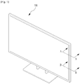
FIG. 1 is a perspective view of a display device according to anembodiment as broadly described herein; -
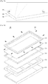
FIG. 2 is an exploded perspective view of the display device shown inFIG. 1 ; -
FIG. 3 is a partial perspective viewof a top case cut away from the display device shown inFIGs. 1 and2 ; -
FIG. 4 is a partial perspective view of an inside of a top case of the display device shown inFIGs. 1 and2 , according to anembodiment as broadly described herein; -
FIG. 5 is a partial perspectiveview of an inside of a top case of the display device shown inFIGs. 1 and2 , according to another embodiment as broadly described herein; -
FIG. 6 is a side sectional view taken along line A-A' shown inFIG. 1 ; -
FIG. 7 is a side sectional view taken along line B-B' shown inFIG. 1 ; -
FIG. 8 is a side sectional viewof the display device shown inFIGs. 1 and2 ; -
FIG. 9 is a perspective view of a display device according to another embodiment as broadly described herein; -
FIG. 10 is an exploded perspective view of the display device shown inFIG. 9 ; -
FIG. 11 is a side sectional view of the display device shown inFIG. 9 ; -
FIG. 12 is a rear perspective view in which a rear cabinet is separated from the display device shown inFIG. 9 ; -
FIG. 13 is a rear perspective view of the display device shown inFIG. 9 ; -
FIG. 14 is an exploded perspectiveview of a display device according to another embodiment; -
FIG. 15 is a side sectional view of the display device shown inFIG. 14 ; -
FIG. 16 is a rear perspective view in which a rear cabinet is separated from the display device shown inFIG. 14 ; and -
FIG. 17 is a rear perspective viewof the display device shown inFIG. 14 . - Hereinafter, when an element is referred to as being 'on' or 'under' another element, it may be directly on/under the element, and one or more intervening elements may also be present. When an element is referred to as being 'on' or 'under', 'under the element' as well as 'on the element'may be included based on the element.
- Certain display devices may include a top case and a rear cover fixedly coupled to a front side and a back side of a display module, with afront cabinet and a rear cabinet coupled to a front surface of the top case and a rear surface of the rear cover so the coupling between the top case and the rear cover and various electronic components are not visible. Although such a front cabinet and rear cabinet provide a clean and neat appearance, the double structure may result in a somewhat broad bezel along an edge portion of the display. A thicker bezelmay cause the screen to appear smaller and may increase the actual size and weight of the product.
- In a display device as embodied and broadly described herein the front cabinet may be omitted so that the bezel is not made unnecessarily thicker, and a number of elements may be reduced.
- As shown in
FIGs. 1 and2 , adisplay device 100 may include atop case 110, adisplay panel 120, aguide panel 130, alight guide panel 140, aback cover 150 and a rear cabinet 160.Thedisplay panel 120, theguide panel 130 and thelight guide panel 140 may be layered sequentiallyto form a display module. Thedisplay panel 120 may selectively transmit light provided from a rear surface therethrough by changing arrangement of liquid crystals. Thedisplay panel 120 may control transparency and color for each pixel so as to display a screen based on image information. A liquid crystal may be injected between two transparent glasses and electric currents may flow to transparent electrodes formed on the transparent glasses to change the arrangement of the liquid crystals for each pixel, such that thedisplay panel 120 may control the transparency of the pixel. - A light source arranged at a back side of the
display panel 120 to provide light may be coupled to theback cover 150 to emit light. The light source may employ a point light source such as a light emitting diode (LED). Thelight guide panel 140 may supply such point light sources to the back side of thedisplay panel 120 uniformly. Thelight guide panel 140 may convert the point light sources into surface light sources and emit the surface light sources in a forward direction uniformly. Thelight guide panel 140 may include a light guide film, a diffusion film and a prism film that are layered sequentially. Other arrangements and/or combinations of films may also be appropriate. - The
guide panel 130 may align thedisplay panel 120 and thelight guide panel 140 including the plurality of films. Referring toFIG. 8 , which is a sectional view of thedisplay device 100, theguide panel 130 may include aseating portion 131 and aguide wall 132. Theseating portion 131 may be formed in a front surface of theguide panel 130 to support an edge portion of a back surface of thedisplay panel 120 and an edge portion of a lateral surface of thedisplay panel 120. Theguide wall 132 may be formed in a lateral surface of theguide panel 130 and the films of thelight guide panel 140 may be disposed on a back side of theguide wall 132. - The
top case 110 is coupled to a front surface of the display module (including thedisplay panel 120,guide panel 130 and light guide panel 140) and theback cover 150 is coupled to a back side of the display module, to fix the resulting layered structure. In this embodiment, the coupling of thetop case 110 and theback cover 150 may support the front and back surfaces of the display module with a predetermined force sufficient to keep each layer of the display moduletogether. - When using a coupling member such as a screw, a relatively strong fastening force may be provided and a head portion of the screw may, in some arrangements, be exposed. Accordingly, an exterior appearance of the display device may be adversely affected, and an auxiliary cabinet may be considered to finish the exterior appearance.
- According to this embodiment, a coupling portion may be provided in a
lateral surface 111 of thetop case 110 and coupled to theback cover 150 and theguide panel 130, such that it is not exposed to the outside. The coupling portion formed in thelateral surface 111 of thetop case 110 may include acoupling projection 117 and a steppedprotrusion 114 that are coupled to acoupling groove 155 of theback cover 150 and a hookingprotrusion 135 of theguide panel 130. - In certain embodiments,
coupling groove 155 may be formed in one of theback cover 150 or theguide panel 130, and the hookingprotrusion 135 may be formed in the other. In other words, thetop case 110 may include a coupling portion configured to be coupled to theback cover 150 and theguide panel 130. - The
coupling groove 135 and thecoupling protrusion 117 may be coupled to each other in a male/female coupling structure inserted in a backward direction from the front surface, to prevent shaking in a lateral direction. The hookingprotrusion 135 and the steppedprotrusion 114 may be coupled to prevent forward shaking of thetop case 110. - The
back cover 150 may be coupled to an inner portion of theguide panel 130 and thelateral surface 111 of thetop case 110 may be coupled to an outer portion of theguide panel 130. Accordingly, theguide panel 130 may be partially cut away to couple the hookingprotrusion 135 or thecoupling groove 155 of theback cover 150 to the coupling portion of thetop cover 110, such that the hookingprotrusion 135 or thecoupling groove 155 formed in theback cover 150 may be exposed to the lateral surface. - The hooking
protrusion 135 may be formed in thetop case 110 and thecoupling groove 155 may be formed in theback cover 150. Alternatively, thecoupling groove 155 may be formed in theguide panel 130. For ease of explanation and illustration, in this embodiment, the hookingprotrusion 135 will be formed in thetop case 110 and thecoupling groove 155 will be formed in theback cover 150, understanding that alternative arrangements may also be appropriate. -
FIG. 3 is a partial perspective view of thetop cover 110 separated from thedisplay device 100. InFIG. 3 , thedisplay panel 120, theguide panel 130 and theback cover 150 are shown. Theback cover 150 is inserted in theguide panel 130 shown inFIG. 2 and thelight guide panel 140 is disposed between theguide panel 130 and the back cover 150.Thecoupling groove 155 is formed in an edge area of theback cover 150. Thecoupling groove 115 is configured to receive acoupling projection 117 formed in thetop case 110. InFIG. 3 , thecoupling groove 155 has a penetrating hole shape and thecoupling projection 117 is inserted in thecoupling groove 155 in a direction toward the front surface. -
FIGS. 4 and 5 are partial perspective views of an inner portion of thetop case 110 having thecoupling projection 117 formed therein. Thecoupling projection 117 is projected inward and extended toward the back surface. InFIGS. 4 and 5 , an end of alateral surface 111 of thetop case 110 is folded inward to form ahem 113, with a predetermined portion of thehem 113 cut and bent to form thecoupling projection 117. Thecoupling projection 117 may employ a double structure using thehem 113 so that thecoupling projection 117 is not exposed to the outside by thetop case 110, which may function as an exterior finishing material. - When the
portion 116 partially cut away in a pulse wave shape is bent inward as shown inFIG. 4 , thecoupling projection 117 projected inward and extended toward the back surface may be formed. Alternatively, the portion may be cut away in a convex shape toward the back surface, and may be bent twice as shown inFIG. 5 , such that acoupling projection 119 projected inward and extended toward the back surface may be formed. - In addition to the embodiments shown in
FIGS. 4 and 5 , the structure of thecoupling projection 117 may vary, as long as the shape thereof is projected inward and extends toward the back surface. Thecoupling projection 117 may be inserted into thecoupling groove 155 from the front surface. Thecoupling groove 155 and thecoupling projection 117 may be insertedly coupled to each other in a male/female coupling structure to fix thetop case 110 and theback cover 150, without moving in a lateral direction. -
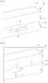
FIG. 6 is a sectional view taken along line A-A' shown inFIG. 1 and shows thecoupling projection 117 coupled to thecoupling groove 155. InFIG. 6 , a lower portion of thetop cover 110 is positioned on the front surface of thedisplay device 100. - The stepped
protrusion 114 and the hookingprotrusion 135 may be provided to prevent thetop case 110 from separating in a forward direction. The hookingprotrusion 135 may formed at an outer surface of theguide panel 130 and a step may be formed at a back surface of theguide panel 130. As shown inFIG. 3 , projection of the hookingprotrusion 135 may gradually increase from the front surface toward the back surface, in other words, the hookingprotrusion 135 may have a triangular-shaped cross section. During coupling, thetop case 110 may slide along the inclined surface to allow the hookingprotrusion 135 to be smoothly coupled to the steppedprotrusion 114. - The stepped
protrusion 114 to be coupled to the hookingprotrusion 135 may be formed in thelateral surface 111 of thetop case 110 in various methods. According to this embodiment, an end of thelateral surface 111 of thetop case 110 is folded inward and ahem 113 is formed to form the steppedprotrusion 114. In a top case formed of a metallic material such as SUS, thehem 113 may be easily processed. - Both of the stepped
protrusion 114 and thecoupling projection 117 may be formed using thehem 113. Thecoupling projection 117 may be positioned closer to the back surface than the steppedprotrusion 114, such that thecoupling groove 155 may be positioned closer to the back surface than the hookingprotrusion 135. -
FIG. 7 is a sectional view taken along line B-B' shown inFIG. 1 , showing the steppedprotrusion 114 formed in thelateral surface 111 of thetop case 110 insertedly fitted to the hookingprotrusion 135 formed in a lateral surface of theguide panel 130. Thecoupling projection 117 is inserted in thecoupling groove 155 to couple thetop case 110 to the front of theback cover 150. After that, the hookingprotrusion 135 and the steppedprotrusion 114 may be engagingly fitted to each other and thetop case 110 may be coupled to theback cover 150 and thedisplay panel 120. - The
hem 113 may be formed along an overall inner edge portion of thelateral surface 111 of thetop case 110. As mentioned above, thehem 113 may be partially cut away to form thecoupling projection 117. The coupling portion may be formed in thehem 113 such that the exterior appearance maybe maintained. - The
lateral surface 111 of the top case at a portion under thedisplay device 100, in other words, facing the floor, is not exposed, when thedisplay device 100 is typically used. A screw may be used in coupling thetop case 110, theback cover 150 and theguide panel 130 to each other in this area. -
FIG. 8 is a side sectional diagram of thedisplay device 100 according to this embodiment. A printed circuit board and various electronic parts configured to control and drive thedisplay device 100 may be mounted at an outer portion of thetop case 110. Arear cabinet 160 may be coupled to thetop case 110 to cover the printed circuit board and other electronic parts. Therear cabinet 160 may be positioned behind the back surface of theback cover 150 and may not affect the exterior appearance. Accordingly, as shown inFIG. 8 , therear cabinet 160 may be coupled to theback cover 150 using ascrew 170, or other fastener as appropriate. -
FIG. 9 is a perspective view of adisplay device 200 according to another embodiment. As shown inFIG. 9 , in the display device according to this embodiment, no front cabinet is provided and atop case 210 configured to fix members of adisplay module screw 270 configured to fasten thetop case 210 and aback cover 250 to each other is not exposed outside. - As shown in
FIG. 10 , thedisplay device 200 may include atop case 210, adisplay panel 220, aguide panel 230, alight guide panel 240, aback cover 250 and arear cabinet 260. - The
display panel 220, theguide panel 230 and thelight guide panel 240 may be layered sequentially to form a display module. Thedisplay panel 220 may selectively transmit light provided from a rear surface there through by changing arrangement of liquid crystals. Thedisplay panel 220 controls a transparency and a color for each of the pixels so as to display a screen based on image information. A liquid crystal is injected between two transparent glasses and electric currents may flow to transparent electrodes formed on the transparent glasses to change the arrangement of the liquid crystals for each pixel, such that thedisplay panel 220 may control the transparency of the pixel. - A light source arranged at a back side of the
display panel 220 to provide light may be coupled to theback cover 250. The light source may use a point light source such as a light emitting diode (LED). Thelight guide panel 240 may supply such point light sources to the back side of thedisplay panel 220 uniformly. Thelight guide panel 240 may convert the point light sources into surface light sources and emit the surface light sources in a forward direction uniformly. Thelight guide panel 240 may include a light guide film, a diffusion film and a prism film that are layered sequentially. - The
guide panel 230 may align thedisplay panel 220 and thelight guide panel 240. Referring toFIG. 11 , theguide panel 230 may include aseating portion 231 and aguide wall 232. Theseating portion 231 may be formed in a front surface of theguide panel 230 to support an edge portion of a back surface of thedisplay panel 220 and an edge portion of a lateral surface of thedisplay panel 220. Theguide wall 232 may be formed in a lateral surface of theguide panel 230 and the films of thelight guide panel 240 may be disposed on a back side of theguide wall 232. - The
top case 210 may be coupled to a front surface of the display module and theback cover 250 may be coupled to a back side of the display module, to fix the layered structure including thedisplay panel 220, theguide panel 230 and thelight guide panel 240. The coupling of thetop case 210 and theback cover 250 may support the front and back surfaces of the display module with a predetermined force sufficient to make each layer of the display module stay together, such that ascrew 270 may be used. - The
screw 270 may provide a relatively strong coupling force, but may also have an exposed head portion. In the embodiment shown inFIGS. 10 to 13 thescrew 270 is coupled to the back surface of the display module and not visibly exposed. - As shown in
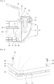
FIG. 11 , an end of thetop case 210 may be bent inward and acoupling surface 231 may be formed toward the back surface, to insert thescrew 270 in the back surface so as to couple theback cover 250 and thetop case 210 to each other. - The
back cover 250 may form a step bent twice in a "" shape. The step may be formed in an edge portion of the back cover and overlapped with the coupling surface 213.The
back cover 250 may also include awing portion 255 extended toward thecoupling surface 213 of thetop case 210. - As shown in
FIG. 12 , thescrew 270 may pass through thewing portion 255 of theback cover 250 and thecoupling surface 213 of thetop case 210 from the back surface, such that theback cover 250 and thetop case 210 may be coupled to each other. - The
top case 210 and theback cover 250 may be coupled to each other by thescrew 270 and therear cabinet 260 may be coupled on theback cover 250, such that thehead portion 271 of thescrew 270 may be covered, and not visibly exposed to the outside. Alternatively, therear cabinet 260 may be coupled to thetop case 210 and theback cover 250 by the screw 270 (seeFIGS. 10 to 13 ). - An edge portion of the
rear cabinet 260 may be seated on thewing portion 255 of theback cover 250 and thescrew 270 may be coupled to thewing portion 255 of theback cover 250 and thecoupling surface 213 formed in the end of thetop case 210, passing through therear cabinet 260 from a back surface of therear cabinet 260. - When even the
rear cabinet 260 is coupled by thescrew 270, no further auxiliary coupling member need be provided to couple therear cabinet 260, and only onescrew 270 may couple the overall structure of thedisplay device 200. Accordingly, an assembly process of the display device may be simplified. - In a case in which even the
rear cabinet 260 is coupled together by thescrew 270, thehead portion 271 of thescrew 270 could be exposed at the back surface of therear cabinet 260. However, the back surface is out of the user's view when thedisplay device 200 is installed. Thus, thehead portion 271 of thescrew 270 may not detract from the exterior appearance. - When a flat
rear cabinet 260 is used, the lateral surface may be somewhat thick. Accordingly, when therear cabinet 260 is formed in a curved shape having a convex center portion extending toward the back surface as shown inFIG. 12 , thedisplay device 200 may appear slimmer. - It may be difficult to couple the curved-shaped
rear cabinet 260 with the convex center portion using thescrew 270, because the edge portion of the curved-shapedrear cabinet 260 may be spaced apart a predetermined distance from thewing portion 255. Therefore, a predetermined edge portion of therear cabinet 260 where thescrew 270 is inserted may have a concave shape so as to be in close contact with thewing portion 255 of theback cover 250. Accordingly, thescrew 270 may penetratingly couple therear cabinet 260, theback cover 250 and thetop case 210 to each other (seeFIG. 11 ). - As the
screw 270 is coupled from the back surface, there may be a predetermined space where an end 272 of thescrew 270 is inserted. As shown inFIG. 11 , a lateral surface of thetop case 210 may be spaced apart a predetermined distance from a lateral surface of the display module, such that a predetermined space may be formed between the lateral surface of the display module. An end 272 of thescrew 270 penetrating therear cabinet 260, theback cover 250 and thetop case 260 may be positioned in this space. - The size of the
front surface 215 of thetop case 210 may be enlarged so that a cross sectional area of the spaced distance is substantially rectangular. Simultaneously, the size of the bezel may be enlarged. To reduce the size of the bezel positioned at the front surface (the size of thefront surface 215 of the top case 210), thelateral surface 211 may have an oblique curved shape to form the spaced distance. When the oblique curved-shapedlateral surface 111 is enlarged in the back surface, a front portion may reduce/maintain the size of the bezel. - The display module may be fixedly disposed between the
back cover 250 and thetop case 210. Especially, a lateral wall of theguide panel 230 configured to cover a lateral surface of the display module may include astep 235 where the ""-shaped bent portion of theback cover 250 for thewing 255 is seated. -
FIG. 12 is a rear perspective view in which a rear cabinet is separated from the display device, andFIG. 13 is a rear perspective view of the display device according to the embodiment. When thecoupling surface 213 of the top cover end and thewing portion 255 of theback cover 250 are coupled to each other by the screw 270as shown inFIG. 12 , thehead 271 of thescrew 270 may be visible only at the back surface and does not detract from the exterior appearance. - As shown in
FIG. 11 , an end 267of therear cabinet 260 may extend toward the front surface so that the end of theback cover 250 is not exposed. Theend 267 may cover thewing portion 255 of theback cover 250 so that thewing portion 255 is not visible. - Referring to
FIGS. 14 to 17 , adisplay device 300 according to another embodiment may include ascrew 370 coupled to alateral surface 311 of atop case 310 and arear cabinet 360 covering ahead 371 of thescrew 370. - The
display device 300 may include atop case 310, adisplay panel 320, aguide panel 330, alight guide panel 340, aback cover 350 and a rear cabinet 360.Like the embodiments mentioned above, the display module may include thedisplay panel 320, theguide panel 330 and thelight guide panel 340 layered sequentially. A light source arranged at a back side of thedisplay panel 320 to provide a light may be coupled to theback cover 350. The detailed description of each element is the same as the corresponding description mentioned above and will be omitted accordingly. - A
screw 370 according to this embodiment may be inserted in a lateral surface of thetop case 310 to couple thetop case 310 to theback cover 350. A lateral surface of thedisplay device 300 may be visible to a user and thelateral surface 311 of thetop case 310 may be covered by therear cabinet 360 so that thehead 371 of thescrew 370 is not visible to the user..Therear cabinet 360 may cover only a predetermined portion of the lateral surface of thetop case 310 while anotherpredetermined portion 312 is exposed. - Referring to
FIG. 15 showing a cross section of the lateral surface of thedisplay device 300, the lateral surface of thetop case 310 may include a firstlateral surface 311 adjacent to a back surface and a secondlateral surface 312 adjacent to a front surface. Thescrew 370 may be inserted in the firstlateral surface 311 and therear cabinet 360 may be coupled to the firstlateral surface 311. - To form continuous surfaces in the second
lateral surface 312 and therear cabinet 360 so that a connected portion between therear cabinet 360 and thetop case 310 is not noticeable, astep 313 may be formed to make the firstlateral surface 311 further recessed than the secondlateral surface 312. A predetermined opening may be formed in the recessed firstlateral surface 311 to insert the screw therein and to form a continuous surface with the secondlateral surface 312 of thetop case 310. - An
end 355 of theback cover 350 may be positioned in an inner portion of the firstlateral surface 311 and thescrew 370 may be fastened via the firstlateral surface 311 of thetop case 310 and theend 355 of theback cover 350. Theend 355 of theback cover 350 may be bent once in a "L" shape and extend toward the back surface. - The
guide panel 330 of the display module may be disposed between the firstlateral surface 311 of thetop case 310 and theend 355 of theback cover 350, to be coupled together with thetop case 310 and theback cover 350. - The
guide panel 330 may further include a steppedportion 335 where the L-shaped bent portion of theback cover 350 is seated. Theguide panel 330 including the steppedportion 335 may guide the disposition of the display module and the coupling of theback cover 350. - The second
lateral surface 312 of thetop case 310 may form the step with the firstlateral surface 311, spaced apart a predetermined distance from the display module. When the secondlateral surface 312 of thetop case 310 is perpendicular to thefront surface 315 of thetop case 310 by enlarging the stepped portion and thefront surface 315 of thetop case 310, the bezel may be enlarged. - As the size of the bezel increases, the appearance of the display device may degrade and the screen may appearsmaller. To reduce the size- of the bezel, the second
lateral surface 312 may be formed in an oblique curved shape as shown inFIG. 15 . - A predetermined portion of the second
lateral surface 312 adjacent to the firstlateral surface 311 may form a step with a lateral surface of thedisplay module lateral surface 312 adjacent to thefront surface 315 of thetop case 310 may be adjacent to the lateral surface of the display module, such that the size of the bezel may be minimized. -
FIG. 16 is a rear perspective view of therear cabinet 360 separated from thedisplay device 300 according to the embodiment ofFIG. 14 , andFIG. 17 is a rear perspective view of thedisplay device 300 according to the embodiment.When therear cover 360 covers thescrew 370 penetrating the firstlateral surface 311 of thetop case 310 and the lateral wall of theback cover 350 as shown inFIG. 16 , the screw is not exposed to the outside as shown inFIG. 17 . - As described above, a display device according to embodiments as broadly described herein includes the top case configured to fix the structure of the display module while not exposing the coupling structure at the lateral surface. Accordingly, a front cabinet may be omitted and the top case may serve as an exterior material, a number of parts may be reduced and cost may be reduced.
- Furthermore, a double structure including a front cabinet covering the overall edge portion of the front surface of the display panel and the top case may be integrated into the single structure, reducing the size of the bezel.
- A display device is provided that may reduce the number of elements provided therein so as to reduce production cost and processes, with a reduced size bezel on a front screen.
- A display device, as embodied and broadly described herein,may include a display module; a back cover configured to support a back surface of the display module; a top case configured to cover an edge portion of a front surface of the display module or a lateral surface of the display module, the top case comprising a coupling portion formed in an lateral surface to be coupled to the lateral surface of the display module and an edge portion of the back cover; and a rear cabinet configured to cover a back surface of the back cover, wherein the lateral surface of the top case is exposed outside.
- The coupling portion may include a coupling projection having a lateral surface projected inward and extended backward, and the coupling projection may be coupled to a coupling groove projected from an edge portion of the back cover or the lateral surface of the display module, with being open toward the front surface.
- The coupling portion may include a stepped protrusion projected toward a front surface formed in an inner edge portion of the lateral surface of the top case; and a hooking protrusion formed in a predetermined portion of a lateral surface of the display module or an edge portion of the back cover, where the coupling groove is not formed, toward a back surface, and the stepped protrusion is engagingly coupled to the hooking protrusion to prevent the separation of the top case.
- The display module may include a light source coupled to the back cover to supply a light to the light diffusion part; a light diffusion part configured to uniformly supply the light supplied by the light source to a front surface; a display panel configured to control a transparency and a color for each of pixels based on image information; and a guide panel configured to lateral edge portions of the display panel and the light diffusion part and to guide the disposition of the display panel and the light diffusion part, and the hooking protrusion may be formed in an outer portion with respect to a lateral surface of the guide panel.
- In another embodiment as broadly described herein, a display device may include a display module; a back cover configured to support a back surface of the display module; a top case configured to cover an edge portion of a front surface of the display module or a lateral surface of the display module, the top case coupled to the back cover; a screw coupled to the top case, with penetrating an edge portion of the back cover; and a rear cabinet configured to cover a back surface of the back cover, with an edge portion coupled to the top case, wherein a predetermined portion of the top case is exposed outside when the top case is coupled to the rear cabinet.
- The back cover may alsoinclude a wing portion extended from an end of the edge portion outward to cover a lateral surface end of the top case, and the screw is coupled to the lateral surface end of the top case toward a back surface, with penetrating the wing portion.
- A lateral surface of the top case may include a first lateral surface adjacent to a back surface of the top case and a second lateral surface adjacent to a front surface of the top case, and an end of an edge portion of the back cover may be bent once in L shape to be extended toward a back surface, and the screw may be coupled to the first lateral surface in a lateral direction, penetrating the bent end of the back cover, and the rear cabinet may be coupled to the first lateral surface.
- A display device as embodied and broadly described herein includes the top case configured to fix the structure of the display module and while not exposing the coupling structure at the lateral surface. Accordingly, a front cabinet may be omitted and the top case may be used as an exterior material.By omitting the front cabinet, the number of parts maybe reduced, and cost may be reduced.
- Furthermore, a double structure including a front cabinet covering the overall edge portion of the front surface of the display panel and atop case may be integrated into the single structure so that the size of the bezel maybe reduced.
- Any reference in this specification to "one embodiment," "an embodiment," "example embodiment," etc., means that a particular feature, structure, or characteristic described in connection with the embodiment is included in at least one embodiment of the invention. The appearances of such phrases in various places in the specification are not necessarily all referring to the same embodiment. Further, when a particular feature, structure, or characteristic is described in connection with any embodiment, it is submitted that it is within the purview of one skilled in the art to effect such feature, structure, or characteristic in connection with other ones of the embodiments.
- Although embodiments have been described with reference to a number of illustrative embodiments thereof, it should be understood that numerous other modifications and embodiments can be devised by those skilled in the art that will fall within the scope of this disclosure.
Claims (10)
- A display device (300), comprising:a display panel (320);a back cover (350) positioned at a rear of the display panel (320);a guide panel (330) positioned at a lateral side of the back cover (350), wherein the guide panel (330) includes a seating portion for seating an edge portion of the display panel (320), and a stepped portion (335) for seating a portion of the back cover (350);a top case (310) having a front part positioned at an edge portion of a front surface of the display panel (320) and a lateral part positioned at a lateral side of the guide panel (330), wherein the lateral part of the top case (310) comprises a first lateral surface (311) and a second lateral surface (312), the first lateral surface (311) being recessed further inward than the second lateral surface (312);a fastener (370) that couples the top case (310), the guide panel (330), and the back cover (350) by penetrating the first lateral surface (311) of the top case (310), the guide panel (330) and the back cover (350); anda rear cabinet (360) that covers the fastener (370) and the first lateral surface (311) of the lateral part of the top case (310),wherein the seating portion of the guide panel (330) seats a back surface of the display panel (320) and the stepped portion (335) of the guide panel (330) seats a front surface of the back cover (350), andwherein the second lateral surface (312) of the lateral part of the top case (310) is exposed to an outside of the display device (300), andwherein the rear cabinet (360) and the second lateral surface (312) of the lateral part of the top case (310) form an exterior surface of the display device (300).
- The display device (300) of claim 1, wherein the second lateral surface (312) of the lateral part of the top case (310) is positioned closer to the front part of the top case (310) than the first lateral surface (311).
- The display device (300) of claim 1, wherein the second lateral surface (312) of the lateral part of the top case (310) has an oblique shape that extends from the front part of the top case (310).
- The display device (300) of claim 1, wherein the back cover (350) has a bent edge portion,
wherein the guide panel (330) further includes a first protruding portion protruding from the seating portion towards a rear side of the display device (300),
wherein the fastener (370) penetrates through a first hole formed at the first lateral surface (311), a second hole formed at the guide panel (330), and a third hole formed at the bent edge portion of the back cover (350), and
wherein a first end (371) of the fastener (370) is placed at the first lateral surface (311) of the lateral part of the top case (310) and a second end (372) of the fastener (370) protrudes through the bent edge portion of the back cover (350). - The display device (300) of claim 4, wherein the stepped portion (335) of the guide panel (330) contacts the bent edge portion of the back cover (350) for seating the back cover (350).
- The display device (300) of claim 1, further comprising a light source positioned at the back cover (350).
- The display device (300) of claim 1, wherein the lateral part of the top case (310) further comprises a step (313) positioned between the first lateral surface (311) and the second lateral surface (312), and
wherein an edge of the rear cabinet (360) faces the step (313). - The display device (300) of claim 1, wherein the first lateral surface (311) comprises horizontal first lateral surfaces and vertical first lateral surfaces, and
wherein a gap exists between the horizontal first lateral surface and the vertical first lateral surface at a corner portion of the top case (310). - The display device (300) of claim 1, wherein the stepped portion (335) is provided at an inner surface of the guide panel (330) and the front surface of back cover (350) is seated on the stepped portion (335).
- The display device (300) of claim 1, wherein the first lateral surface (311) of the lateral part of the top case (310) contacts the guide panel (330) and the second lateral surface (312) is spaced from the guide panel (330), and wherein the exterior surface of the display device (300) that is formed by the rear cabinet (360) and the second lateral surface (312) of the lateral part of the top case (310) is continuous.
Priority Applications (2)
| Application Number | Priority Date | Filing Date | Title |
|---|---|---|---|
| EP22179150.2A EP4083697A1 (en) | 2013-03-08 | 2013-06-04 | Display device |
| EP18195321.7A EP3435360B1 (en) | 2013-03-08 | 2013-06-04 | Display device |
Applications Claiming Priority (4)
| Application Number | Priority Date | Filing Date | Title |
|---|---|---|---|
| KR1020130024854A KR102049857B1 (en) | 2013-03-08 | 2013-03-08 | Display device |
| KR1020130024856A KR102049859B1 (en) | 2013-03-08 | 2013-03-08 | Display Device |
| KR1020130024855A KR102049858B1 (en) | 2013-03-08 | 2013-03-08 | Display Device |
| PCT/KR2013/004905 WO2014137032A1 (en) | 2013-03-08 | 2013-06-04 | Display device |
Related Child Applications (3)
| Application Number | Title | Priority Date | Filing Date |
|---|---|---|---|
| EP18195321.7A Division EP3435360B1 (en) | 2013-03-08 | 2013-06-04 | Display device |
| EP18195321.7A Division-Into EP3435360B1 (en) | 2013-03-08 | 2013-06-04 | Display device |
| EP22179150.2A Division EP4083697A1 (en) | 2013-03-08 | 2013-06-04 | Display device |
Publications (3)
| Publication Number | Publication Date |
|---|---|
| EP2965307A1 EP2965307A1 (en) | 2016-01-13 |
| EP2965307A4 EP2965307A4 (en) | 2016-11-23 |
| EP2965307B1 true EP2965307B1 (en) | 2019-01-16 |
Family
ID=51487597
Family Applications (3)
| Application Number | Title | Priority Date | Filing Date |
|---|---|---|---|
| EP13877113.4A Active EP2965307B1 (en) | 2013-03-08 | 2013-06-04 | Display device |
| EP18195321.7A Active EP3435360B1 (en) | 2013-03-08 | 2013-06-04 | Display device |
| EP22179150.2A Pending EP4083697A1 (en) | 2013-03-08 | 2013-06-04 | Display device |
Family Applications After (2)
| Application Number | Title | Priority Date | Filing Date |
|---|---|---|---|
| EP18195321.7A Active EP3435360B1 (en) | 2013-03-08 | 2013-06-04 | Display device |
| EP22179150.2A Pending EP4083697A1 (en) | 2013-03-08 | 2013-06-04 | Display device |
Country Status (5)
| Country | Link |
|---|---|
| US (5) | US9297947B2 (en) |
| EP (3) | EP2965307B1 (en) |
| CN (2) | CN107526200B (en) |
| DE (1) | DE202013012611U1 (en) |
| WO (1) | WO2014137032A1 (en) |
Families Citing this family (18)
| Publication number | Priority date | Publication date | Assignee | Title |
|---|---|---|---|---|
| WO2014137032A1 (en) | 2013-03-08 | 2014-09-12 | Lg Electronics Inc. | Display device |
| CN103792712A (en) * | 2014-01-20 | 2014-05-14 | 深圳市华星光电技术有限公司 | Cooling structure of liquid crystal display module |
| KR102145892B1 (en) * | 2014-01-22 | 2020-08-19 | 엘지전자 주식회사 | Display Apparatus |
| US9274362B2 (en) * | 2014-03-21 | 2016-03-01 | Shenzhen China Star Optoelectronics Technology Co., Ltd | Curved liquid crystal display device |
| US9323086B2 (en) * | 2014-03-21 | 2016-04-26 | Shenzhen China Star Optoelectronics Technology Co., Ltd. | Curved liquid crystal display device |
| KR102417629B1 (en) * | 2015-10-28 | 2022-07-05 | 엘지디스플레이 주식회사 | Supporting cover for curved display and curved display apparatus comprising the same |
| JP6717677B2 (en) * | 2016-06-14 | 2020-07-01 | クラリオン株式会社 | Display device |
| KR102528952B1 (en) * | 2016-06-28 | 2023-05-03 | 엘지디스플레이 주식회사 | Display device |
| KR101866314B1 (en) * | 2016-07-12 | 2018-06-12 | (주)코텍 | Curved type display device |
| JP6925797B2 (en) * | 2016-10-18 | 2021-08-25 | アルパイン株式会社 | Display device and how to assemble the display device |
| JP2018072505A (en) * | 2016-10-27 | 2018-05-10 | 船井電機株式会社 | Display device |
| DE102017204600A1 (en) * | 2017-03-20 | 2018-09-20 | Robert Bosch Gmbh | A connector for connecting two housing parts and housings comprising two housing parts and at least one connector |
| KR102357930B1 (en) | 2017-08-30 | 2022-02-03 | 엘지디스플레이 주식회사 | Display device |
| JP6937070B2 (en) * | 2017-10-04 | 2021-09-22 | アルパイン株式会社 | Panel member fixing device |
| CN108153009A (en) * | 2018-01-25 | 2018-06-12 | 江苏凡润电子有限公司 | A kind of processing mold and its processing method of liquid crystal display double flare frame |
| CN109688739A (en) * | 2019-01-23 | 2019-04-26 | 黑河学院 | A kind of video analysis processing unit protective shell convenient for quickly assembling |
| US10835035B1 (en) * | 2019-09-10 | 2020-11-17 | Chen-Source Inc. | Accommodation cabinet with handtoollessly assembled frame body |
| CN113805370A (en) * | 2020-06-11 | 2021-12-17 | 京东方科技集团股份有限公司 | Curved surface display module assembly and curved surface display device |
Family Cites Families (40)
| Publication number | Priority date | Publication date | Assignee | Title |
|---|---|---|---|---|
| JP3285011B2 (en) * | 1999-07-14 | 2002-05-27 | 日本電気株式会社 | Liquid crystal display |
| KR100619582B1 (en) * | 1999-10-08 | 2006-09-01 | 삼성전자주식회사 | Liquid crystal display module, liquid crystal display device contain the liquid crystal display module and method for assembling the same |
| KR100381787B1 (en) * | 2000-12-27 | 2003-04-26 | 삼성전자주식회사 | Displaying Apparatus |
| KR100793728B1 (en) * | 2001-09-14 | 2008-01-10 | 삼성전자주식회사 | Liquid crystal display device |
| KR20030073783A (en) * | 2002-03-13 | 2003-09-19 | 엘지전자 주식회사 | Structure for Engagement of Flat Panel Display |
| JP4065702B2 (en) * | 2002-03-22 | 2008-03-26 | 株式会社 日立ディスプレイズ | Image display device |
| KR100878220B1 (en) * | 2002-05-24 | 2009-01-13 | 삼성전자주식회사 | Liquid crystal display device |
| KR100840715B1 (en) * | 2002-05-28 | 2008-06-23 | 삼성전자주식회사 | Back light assembly and liquid crystal display having the same |
| JP3789401B2 (en) | 2002-06-24 | 2006-06-21 | Nec液晶テクノロジー株式会社 | Liquid crystal module and liquid crystal monitor using the same |
| KR100913307B1 (en) | 2002-12-12 | 2009-08-26 | 삼성전자주식회사 | Backlight assembly and liquid crystal display device having the same |
| KR100487435B1 (en) * | 2002-12-24 | 2005-05-03 | 엘지.필립스 엘시디 주식회사 | liquid crystal display device module having a mounting frame combination structure |
| JP4260519B2 (en) | 2003-03-31 | 2009-04-30 | シャープ株式会社 | Liquid crystal display |
| TW594171B (en) | 2003-04-18 | 2004-06-21 | Hannstar Display Corp | Liquid crystal display and light source device thereof |
| JP4557822B2 (en) | 2005-06-30 | 2010-10-06 | シャープ株式会社 | Liquid crystal panel mounting method and holding device |
| JP4237748B2 (en) * | 2005-12-09 | 2009-03-11 | カシオ計算機株式会社 | Display module |
| KR101195227B1 (en) * | 2005-12-14 | 2012-10-29 | 삼성디스플레이 주식회사 | Liquid crystal display |
| KR101232043B1 (en) * | 2006-02-21 | 2013-02-12 | 삼성디스플레이 주식회사 | Liquid crystal display apparatus |
| KR20080057890A (en) * | 2006-12-21 | 2008-06-25 | 삼성전자주식회사 | Display device |
| KR101339939B1 (en) * | 2007-03-02 | 2013-12-11 | 삼성디스플레이 주식회사 | Display Device And Method of Compensating Pressure Thereof |
| JP2008216934A (en) | 2007-03-08 | 2008-09-18 | Mitsubishi Electric Corp | Display device |
| TWI361308B (en) * | 2007-06-21 | 2012-04-01 | Chimei Innolux Corp | Backlight module and liquid crystal display device |
| US8284343B2 (en) | 2007-09-14 | 2012-10-09 | Sharp Kabushiki Kaisha | Frame structure and display equipped with the same |
| KR101394143B1 (en) * | 2008-03-19 | 2014-05-15 | 삼성디스플레이 주식회사 | Display assembly and dispaly device having the same |
| KR101003810B1 (en) | 2008-05-06 | 2010-12-23 | 한국과학기술원 | Power Amplifier |
| BRPI0923942A2 (en) | 2009-01-13 | 2016-01-12 | Sharp Kk | lighting device, display device and television receiver |
| JP2011013506A (en) | 2009-07-02 | 2011-01-20 | Sharp Corp | Display device |
| KR101598372B1 (en) | 2009-09-18 | 2016-02-29 | 엘지디스플레이 주식회사 | Liquid crystal display device |
| EP2515028B1 (en) * | 2009-12-18 | 2017-05-03 | Sharp Kabushiki Kaisha | Illuminating device, display device, and television receiver |
| CN102238816B (en) * | 2010-04-30 | 2014-03-26 | 鸿富锦精密工业(深圳)有限公司 | Electronic device |
| JP2012058611A (en) | 2010-09-10 | 2012-03-22 | Sharp Corp | Liquid crystal display device |
| KR20120030821A (en) | 2010-09-20 | 2012-03-29 | 삼성전자주식회사 | Back light unit and liquid crystal display having the same |
| US8913208B2 (en) * | 2010-11-23 | 2014-12-16 | Lg Display Co., Ltd. | Liquid crystal module capable of preventing display device from being darkly displayed |
| KR101295358B1 (en) * | 2011-03-16 | 2013-08-12 | 삼성전자주식회사 | Liquid crystal display and led module thereof |
| KR20130019597A (en) * | 2011-08-17 | 2013-02-27 | 삼성전자주식회사 | Liquid crystal panel assembly and liquid crystal display apparatue |
| JP2013101203A (en) | 2011-11-08 | 2013-05-23 | Funai Electric Co Ltd | Display device and television device |
| US8947614B2 (en) * | 2012-08-21 | 2015-02-03 | Shenzhen China Star Optoelectronics Technology Co., Ltd. | Frameless liquid crystal display device |
| US20140132877A1 (en) * | 2012-11-13 | 2014-05-15 | Westinghouse Digital, Llc | Liquid crystal display, and configuration thereof |
| WO2014137032A1 (en) | 2013-03-08 | 2014-09-12 | Lg Electronics Inc. | Display device |
| WO2015093396A1 (en) * | 2013-12-18 | 2015-06-25 | シャープ株式会社 | Illumination device and display device |
| US9860479B2 (en) * | 2013-12-25 | 2018-01-02 | Funai Electric Co., Ltd. | Display apparatus |
-
2013
- 2013-06-04 WO PCT/KR2013/004905 patent/WO2014137032A1/en active Application Filing
- 2013-06-04 EP EP13877113.4A patent/EP2965307B1/en active Active
- 2013-06-04 CN CN201710847378.9A patent/CN107526200B/en active Active
- 2013-06-04 EP EP18195321.7A patent/EP3435360B1/en active Active
- 2013-06-04 CN CN201380074338.5A patent/CN105009187B/en active Active
- 2013-06-04 EP EP22179150.2A patent/EP4083697A1/en active Pending
- 2013-06-04 DE DE202013012611.6U patent/DE202013012611U1/en not_active Expired - Lifetime
- 2013-06-14 US US13/918,131 patent/US9297947B2/en active Active
-
2016
- 2016-01-06 US US14/989,420 patent/US9606388B2/en active Active
-
2017
- 2017-01-25 US US15/415,490 patent/US10108037B2/en active Active
-
2018
- 2018-08-14 US US16/103,689 patent/US10649258B2/en active Active
-
2020
- 2020-03-26 US US16/830,674 patent/US11209682B2/en active Active
Non-Patent Citations (1)
| Title |
|---|
| None * |
Also Published As
| Publication number | Publication date |
|---|---|
| US20170131590A1 (en) | 2017-05-11 |
| US20200225530A1 (en) | 2020-07-16 |
| CN105009187B (en) | 2018-02-06 |
| CN107526200A (en) | 2017-12-29 |
| CN105009187A (en) | 2015-10-28 |
| US10649258B2 (en) | 2020-05-12 |
| EP2965307A4 (en) | 2016-11-23 |
| US20140254192A1 (en) | 2014-09-11 |
| DE202013012611U1 (en) | 2017-11-24 |
| EP2965307A1 (en) | 2016-01-13 |
| WO2014137032A1 (en) | 2014-09-12 |
| EP3435360B1 (en) | 2022-08-03 |
| US9606388B2 (en) | 2017-03-28 |
| US11209682B2 (en) | 2021-12-28 |
| US9297947B2 (en) | 2016-03-29 |
| EP4083697A1 (en) | 2022-11-02 |
| EP3435360A1 (en) | 2019-01-30 |
| US10108037B2 (en) | 2018-10-23 |
| CN107526200B (en) | 2021-05-07 |
| US20180356673A1 (en) | 2018-12-13 |
| US20160116790A1 (en) | 2016-04-28 |
Similar Documents
| Publication | Publication Date | Title |
|---|---|---|
| EP2965307B1 (en) | Display device | |
| KR101707531B1 (en) | Display apparatus | |
| US10884276B2 (en) | Display device with simplified appearance structure and improved coupling arrangement | |
| US20100046193A1 (en) | Display apparatus | |
| KR101347575B1 (en) | Display Apparatus | |
| US20080298001A1 (en) | Display apparatus | |
| US20060018106A1 (en) | Frame assembly and electronic device | |
| KR101716569B1 (en) | HOUSING FOR BEZELlESS DISPLAY DEVICE | |
| KR20150069802A (en) | Display device | |
| KR20130005217A (en) | Flat panel type image panel display device and mathod for assembling the same | |
| KR20100113196A (en) | Display apparatus | |
| KR102049859B1 (en) | Display Device | |
| KR102049858B1 (en) | Display Device | |
| JP7325012B2 (en) | image display device | |
| KR20140110470A (en) | Display device | |
| CN220235178U (en) | Display device | |
| US20150195925A1 (en) | Display device | |
| KR20170135432A (en) | Display device | |
| KR20150011934A (en) | Slim monitor | |
| KR20110047465A (en) | Display device | |
| KR20110080314A (en) | Display device |
Legal Events
| Date | Code | Title | Description |
|---|---|---|---|
| PUAI | Public reference made under article 153(3) epc to a published international application that has entered the european phase |
Free format text: ORIGINAL CODE: 0009012 |
|
| 17P | Request for examination filed |
Effective date: 20150908 |
|
| AK | Designated contracting states |
Kind code of ref document: A1 Designated state(s): AL AT BE BG CH CY CZ DE DK EE ES FI FR GB GR HR HU IE IS IT LI LT LU LV MC MK MT NL NO PL PT RO RS SE SI SK SM TR |
|
| AX | Request for extension of the european patent |
Extension state: BA ME |
|
| DAX | Request for extension of the european patent (deleted) | ||
| A4 | Supplementary search report drawn up and despatched |
Effective date: 20161025 |
|
| RIC1 | Information provided on ipc code assigned before grant |
Ipc: G09F 9/00 20060101AFI20161019BHEP |
|
| STAA | Information on the status of an ep patent application or granted ep patent |
Free format text: STATUS: EXAMINATION IS IN PROGRESS |
|
| 17Q | First examination report despatched |
Effective date: 20180122 |
|
| GRAP | Despatch of communication of intention to grant a patent |
Free format text: ORIGINAL CODE: EPIDOSNIGR1 |
|
| STAA | Information on the status of an ep patent application or granted ep patent |
Free format text: STATUS: GRANT OF PATENT IS INTENDED |
|
| INTG | Intention to grant announced |
Effective date: 20180727 |
|
| GRAS | Grant fee paid |
Free format text: ORIGINAL CODE: EPIDOSNIGR3 |
|
| GRAA | (expected) grant |
Free format text: ORIGINAL CODE: 0009210 |
|
| STAA | Information on the status of an ep patent application or granted ep patent |
Free format text: STATUS: THE PATENT HAS BEEN GRANTED |
|
| AK | Designated contracting states |
Kind code of ref document: B1 Designated state(s): AL AT BE BG CH CY CZ DE DK EE ES FI FR GB GR HR HU IE IS IT LI LT LU LV MC MK MT NL NO PL PT RO RS SE SI SK SM TR |
|
| REG | Reference to a national code |
Ref country code: GB Ref legal event code: FG4D |
|
| REG | Reference to a national code |
Ref country code: CH Ref legal event code: EP |
|
| REG | Reference to a national code |
Ref country code: IE Ref legal event code: FG4D |
|
| REG | Reference to a national code |
Ref country code: DE Ref legal event code: R096 Ref document number: 602013050064 Country of ref document: DE |
|
| REG | Reference to a national code |
Ref country code: AT Ref legal event code: REF Ref document number: 1090310 Country of ref document: AT Kind code of ref document: T Effective date: 20190215 |
|
| REG | Reference to a national code |
Ref country code: NL Ref legal event code: FP |
|
| REG | Reference to a national code |
Ref country code: LT Ref legal event code: MG4D |
|
| REG | Reference to a national code |
Ref country code: AT Ref legal event code: MK05 Ref document number: 1090310 Country of ref document: AT Kind code of ref document: T Effective date: 20190116 |
|
| PG25 | Lapsed in a contracting state [announced via postgrant information from national office to epo] |
Ref country code: SE Free format text: LAPSE BECAUSE OF FAILURE TO SUBMIT A TRANSLATION OF THE DESCRIPTION OR TO PAY THE FEE WITHIN THE PRESCRIBED TIME-LIMIT Effective date: 20190116 Ref country code: PL Free format text: LAPSE BECAUSE OF FAILURE TO SUBMIT A TRANSLATION OF THE DESCRIPTION OR TO PAY THE FEE WITHIN THE PRESCRIBED TIME-LIMIT Effective date: 20190116 Ref country code: LT Free format text: LAPSE BECAUSE OF FAILURE TO SUBMIT A TRANSLATION OF THE DESCRIPTION OR TO PAY THE FEE WITHIN THE PRESCRIBED TIME-LIMIT Effective date: 20190116 Ref country code: ES Free format text: LAPSE BECAUSE OF FAILURE TO SUBMIT A TRANSLATION OF THE DESCRIPTION OR TO PAY THE FEE WITHIN THE PRESCRIBED TIME-LIMIT Effective date: 20190116 Ref country code: NO Free format text: LAPSE BECAUSE OF FAILURE TO SUBMIT A TRANSLATION OF THE DESCRIPTION OR TO PAY THE FEE WITHIN THE PRESCRIBED TIME-LIMIT Effective date: 20190416 Ref country code: PT Free format text: LAPSE BECAUSE OF FAILURE TO SUBMIT A TRANSLATION OF THE DESCRIPTION OR TO PAY THE FEE WITHIN THE PRESCRIBED TIME-LIMIT Effective date: 20190516 Ref country code: FI Free format text: LAPSE BECAUSE OF FAILURE TO SUBMIT A TRANSLATION OF THE DESCRIPTION OR TO PAY THE FEE WITHIN THE PRESCRIBED TIME-LIMIT Effective date: 20190116 |
|
| PG25 | Lapsed in a contracting state [announced via postgrant information from national office to epo] |
Ref country code: IS Free format text: LAPSE BECAUSE OF FAILURE TO SUBMIT A TRANSLATION OF THE DESCRIPTION OR TO PAY THE FEE WITHIN THE PRESCRIBED TIME-LIMIT Effective date: 20190516 Ref country code: GR Free format text: LAPSE BECAUSE OF FAILURE TO SUBMIT A TRANSLATION OF THE DESCRIPTION OR TO PAY THE FEE WITHIN THE PRESCRIBED TIME-LIMIT Effective date: 20190417 Ref country code: BG Free format text: LAPSE BECAUSE OF FAILURE TO SUBMIT A TRANSLATION OF THE DESCRIPTION OR TO PAY THE FEE WITHIN THE PRESCRIBED TIME-LIMIT Effective date: 20190416 Ref country code: RS Free format text: LAPSE BECAUSE OF FAILURE TO SUBMIT A TRANSLATION OF THE DESCRIPTION OR TO PAY THE FEE WITHIN THE PRESCRIBED TIME-LIMIT Effective date: 20190116 Ref country code: LV Free format text: LAPSE BECAUSE OF FAILURE TO SUBMIT A TRANSLATION OF THE DESCRIPTION OR TO PAY THE FEE WITHIN THE PRESCRIBED TIME-LIMIT Effective date: 20190116 Ref country code: HR Free format text: LAPSE BECAUSE OF FAILURE TO SUBMIT A TRANSLATION OF THE DESCRIPTION OR TO PAY THE FEE WITHIN THE PRESCRIBED TIME-LIMIT Effective date: 20190116 |
|
| REG | Reference to a national code |
Ref country code: DE Ref legal event code: R097 Ref document number: 602013050064 Country of ref document: DE |
|
| PG25 | Lapsed in a contracting state [announced via postgrant information from national office to epo] |
Ref country code: RO Free format text: LAPSE BECAUSE OF FAILURE TO SUBMIT A TRANSLATION OF THE DESCRIPTION OR TO PAY THE FEE WITHIN THE PRESCRIBED TIME-LIMIT Effective date: 20190116 Ref country code: AL Free format text: LAPSE BECAUSE OF FAILURE TO SUBMIT A TRANSLATION OF THE DESCRIPTION OR TO PAY THE FEE WITHIN THE PRESCRIBED TIME-LIMIT Effective date: 20190116 Ref country code: CZ Free format text: LAPSE BECAUSE OF FAILURE TO SUBMIT A TRANSLATION OF THE DESCRIPTION OR TO PAY THE FEE WITHIN THE PRESCRIBED TIME-LIMIT Effective date: 20190116 Ref country code: SK Free format text: LAPSE BECAUSE OF FAILURE TO SUBMIT A TRANSLATION OF THE DESCRIPTION OR TO PAY THE FEE WITHIN THE PRESCRIBED TIME-LIMIT Effective date: 20190116 Ref country code: DK Free format text: LAPSE BECAUSE OF FAILURE TO SUBMIT A TRANSLATION OF THE DESCRIPTION OR TO PAY THE FEE WITHIN THE PRESCRIBED TIME-LIMIT Effective date: 20190116 Ref country code: AT Free format text: LAPSE BECAUSE OF FAILURE TO SUBMIT A TRANSLATION OF THE DESCRIPTION OR TO PAY THE FEE WITHIN THE PRESCRIBED TIME-LIMIT Effective date: 20190116 Ref country code: EE Free format text: LAPSE BECAUSE OF FAILURE TO SUBMIT A TRANSLATION OF THE DESCRIPTION OR TO PAY THE FEE WITHIN THE PRESCRIBED TIME-LIMIT Effective date: 20190116 |
|
| PLBE | No opposition filed within time limit |
Free format text: ORIGINAL CODE: 0009261 |
|
| STAA | Information on the status of an ep patent application or granted ep patent |
Free format text: STATUS: NO OPPOSITION FILED WITHIN TIME LIMIT |
|
| PG25 | Lapsed in a contracting state [announced via postgrant information from national office to epo] |
Ref country code: SM Free format text: LAPSE BECAUSE OF FAILURE TO SUBMIT A TRANSLATION OF THE DESCRIPTION OR TO PAY THE FEE WITHIN THE PRESCRIBED TIME-LIMIT Effective date: 20190116 |
|
| 26N | No opposition filed |
Effective date: 20191017 |
|
| PG25 | Lapsed in a contracting state [announced via postgrant information from national office to epo] |
Ref country code: MC Free format text: LAPSE BECAUSE OF FAILURE TO SUBMIT A TRANSLATION OF THE DESCRIPTION OR TO PAY THE FEE WITHIN THE PRESCRIBED TIME-LIMIT Effective date: 20190116 |
|
| REG | Reference to a national code |
Ref country code: CH Ref legal event code: PL |
|
| PG25 | Lapsed in a contracting state [announced via postgrant information from national office to epo] |
Ref country code: SI Free format text: LAPSE BECAUSE OF FAILURE TO SUBMIT A TRANSLATION OF THE DESCRIPTION OR TO PAY THE FEE WITHIN THE PRESCRIBED TIME-LIMIT Effective date: 20190116 |
|
| REG | Reference to a national code |
Ref country code: BE Ref legal event code: MM Effective date: 20190630 |
|
| PG25 | Lapsed in a contracting state [announced via postgrant information from national office to epo] |
Ref country code: TR Free format text: LAPSE BECAUSE OF FAILURE TO SUBMIT A TRANSLATION OF THE DESCRIPTION OR TO PAY THE FEE WITHIN THE PRESCRIBED TIME-LIMIT Effective date: 20190116 |
|
| PG25 | Lapsed in a contracting state [announced via postgrant information from national office to epo] |
Ref country code: IE Free format text: LAPSE BECAUSE OF NON-PAYMENT OF DUE FEES Effective date: 20190604 |
|
| PG25 | Lapsed in a contracting state [announced via postgrant information from national office to epo] |
Ref country code: LU Free format text: LAPSE BECAUSE OF NON-PAYMENT OF DUE FEES Effective date: 20190604 Ref country code: BE Free format text: LAPSE BECAUSE OF NON-PAYMENT OF DUE FEES Effective date: 20190630 Ref country code: LI Free format text: LAPSE BECAUSE OF NON-PAYMENT OF DUE FEES Effective date: 20190630 Ref country code: CH Free format text: LAPSE BECAUSE OF NON-PAYMENT OF DUE FEES Effective date: 20190630 |
|
| PG25 | Lapsed in a contracting state [announced via postgrant information from national office to epo] |
Ref country code: CY Free format text: LAPSE BECAUSE OF FAILURE TO SUBMIT A TRANSLATION OF THE DESCRIPTION OR TO PAY THE FEE WITHIN THE PRESCRIBED TIME-LIMIT Effective date: 20190116 |
|
| PG25 | Lapsed in a contracting state [announced via postgrant information from national office to epo] |
Ref country code: HU Free format text: LAPSE BECAUSE OF FAILURE TO SUBMIT A TRANSLATION OF THE DESCRIPTION OR TO PAY THE FEE WITHIN THE PRESCRIBED TIME-LIMIT; INVALID AB INITIO Effective date: 20130604 Ref country code: MT Free format text: LAPSE BECAUSE OF FAILURE TO SUBMIT A TRANSLATION OF THE DESCRIPTION OR TO PAY THE FEE WITHIN THE PRESCRIBED TIME-LIMIT Effective date: 20190116 |
|
| PG25 | Lapsed in a contracting state [announced via postgrant information from national office to epo] |
Ref country code: MK Free format text: LAPSE BECAUSE OF FAILURE TO SUBMIT A TRANSLATION OF THE DESCRIPTION OR TO PAY THE FEE WITHIN THE PRESCRIBED TIME-LIMIT Effective date: 20190116 |
|
| P01 | Opt-out of the competence of the unified patent court (upc) registered |
Effective date: 20230524 |
|
| PGFP | Annual fee paid to national office [announced via postgrant information from national office to epo] |
Ref country code: NL Payment date: 20230508 Year of fee payment: 11 Ref country code: IT Payment date: 20230509 Year of fee payment: 11 Ref country code: FR Payment date: 20230510 Year of fee payment: 11 Ref country code: DE Payment date: 20230508 Year of fee payment: 11 |
|
| PGFP | Annual fee paid to national office [announced via postgrant information from national office to epo] |
Ref country code: GB Payment date: 20230509 Year of fee payment: 11 |