EP2964921B1 - Mehrwellengasturbinentriebwerk - Google Patents
Mehrwellengasturbinentriebwerk Download PDFInfo
- Publication number
- EP2964921B1 EP2964921B1 EP13819137.4A EP13819137A EP2964921B1 EP 2964921 B1 EP2964921 B1 EP 2964921B1 EP 13819137 A EP13819137 A EP 13819137A EP 2964921 B1 EP2964921 B1 EP 2964921B1
- Authority
- EP
- European Patent Office
- Prior art keywords
- gearbox
- power
- gas turbine
- turbine engine
- coupled
- Prior art date
- Legal status (The legal status is an assumption and is not a legal conclusion. Google has not performed a legal analysis and makes no representation as to the accuracy of the status listed.)
- Active
Links
- 239000000446 fuel Substances 0.000 description 4
- 230000009467 reduction Effects 0.000 description 4
- 230000008901 benefit Effects 0.000 description 3
- 239000012530 fluid Substances 0.000 description 3
- 230000006870 function Effects 0.000 description 3
- 238000012986 modification Methods 0.000 description 3
- 230000004048 modification Effects 0.000 description 3
- 230000007423 decrease Effects 0.000 description 2
- 230000004075 alteration Effects 0.000 description 1
- 230000033228 biological regulation Effects 0.000 description 1
- 230000005540 biological transmission Effects 0.000 description 1
- 230000006835 compression Effects 0.000 description 1
- 238000007906 compression Methods 0.000 description 1
- 239000000284 extract Substances 0.000 description 1
- 229930195733 hydrocarbon Natural products 0.000 description 1
- 150000002430 hydrocarbons Chemical class 0.000 description 1
- 230000006872 improvement Effects 0.000 description 1
- 238000000034 method Methods 0.000 description 1
- 239000000203 mixture Substances 0.000 description 1
- 239000013618 particulate matter Substances 0.000 description 1
- 230000001737 promoting effect Effects 0.000 description 1
Images


Classifications
-
- F—MECHANICAL ENGINEERING; LIGHTING; HEATING; WEAPONS; BLASTING
- F02—COMBUSTION ENGINES; HOT-GAS OR COMBUSTION-PRODUCT ENGINE PLANTS
- F02C—GAS-TURBINE PLANTS; AIR INTAKES FOR JET-PROPULSION PLANTS; CONTROLLING FUEL SUPPLY IN AIR-BREATHING JET-PROPULSION PLANTS
- F02C7/00—Features, components parts, details or accessories, not provided for in, or of interest apart form groups F02C1/00 - F02C6/00; Air intakes for jet-propulsion plants
- F02C7/36—Power transmission arrangements between the different shafts of the gas turbine plant, or between the gas-turbine plant and the power user
-
- B—PERFORMING OPERATIONS; TRANSPORTING
- B64—AIRCRAFT; AVIATION; COSMONAUTICS
- B64C—AEROPLANES; HELICOPTERS
- B64C11/00—Propellers, e.g. of ducted type; Features common to propellers and rotors for rotorcraft
- B64C11/46—Arrangements of, or constructional features peculiar to, multiple propellers
- B64C11/48—Units of two or more coaxial propellers
-
- B—PERFORMING OPERATIONS; TRANSPORTING
- B64—AIRCRAFT; AVIATION; COSMONAUTICS
- B64D—EQUIPMENT FOR FITTING IN OR TO AIRCRAFT; FLIGHT SUITS; PARACHUTES; ARRANGEMENT OR MOUNTING OF POWER PLANTS OR PROPULSION TRANSMISSIONS IN AIRCRAFT
- B64D27/00—Arrangement or mounting of power plants in aircraft; Aircraft characterised by the type or position of power plants
- B64D27/02—Aircraft characterised by the type or position of power plants
- B64D27/10—Aircraft characterised by the type or position of power plants of gas-turbine type
-
- F—MECHANICAL ENGINEERING; LIGHTING; HEATING; WEAPONS; BLASTING
- F01—MACHINES OR ENGINES IN GENERAL; ENGINE PLANTS IN GENERAL; STEAM ENGINES
- F01D—NON-POSITIVE DISPLACEMENT MACHINES OR ENGINES, e.g. STEAM TURBINES
- F01D15/00—Adaptations of machines or engines for special use; Combinations of engines with devices driven thereby
- F01D15/08—Adaptations for driving, or combinations with, pumps
-
- F—MECHANICAL ENGINEERING; LIGHTING; HEATING; WEAPONS; BLASTING
- F01—MACHINES OR ENGINES IN GENERAL; ENGINE PLANTS IN GENERAL; STEAM ENGINES
- F01D—NON-POSITIVE DISPLACEMENT MACHINES OR ENGINES, e.g. STEAM TURBINES
- F01D15/00—Adaptations of machines or engines for special use; Combinations of engines with devices driven thereby
- F01D15/10—Adaptations for driving, or combinations with, electric generators
-
- F—MECHANICAL ENGINEERING; LIGHTING; HEATING; WEAPONS; BLASTING
- F02—COMBUSTION ENGINES; HOT-GAS OR COMBUSTION-PRODUCT ENGINE PLANTS
- F02C—GAS-TURBINE PLANTS; AIR INTAKES FOR JET-PROPULSION PLANTS; CONTROLLING FUEL SUPPLY IN AIR-BREATHING JET-PROPULSION PLANTS
- F02C3/00—Gas-turbine plants characterised by the use of combustion products as the working fluid
- F02C3/04—Gas-turbine plants characterised by the use of combustion products as the working fluid having a turbine driving a compressor
- F02C3/107—Gas-turbine plants characterised by the use of combustion products as the working fluid having a turbine driving a compressor with two or more rotors connected by power transmission
-
- F—MECHANICAL ENGINEERING; LIGHTING; HEATING; WEAPONS; BLASTING
- F04—POSITIVE - DISPLACEMENT MACHINES FOR LIQUIDS; PUMPS FOR LIQUIDS OR ELASTIC FLUIDS
- F04D—NON-POSITIVE-DISPLACEMENT PUMPS
- F04D25/00—Pumping installations or systems
- F04D25/02—Units comprising pumps and their driving means
- F04D25/04—Units comprising pumps and their driving means the pump being fluid-driven
- F04D25/045—Units comprising pumps and their driving means the pump being fluid-driven the pump wheel carrying the fluid driving means, e.g. turbine blades
-
- F—MECHANICAL ENGINEERING; LIGHTING; HEATING; WEAPONS; BLASTING
- F05—INDEXING SCHEMES RELATING TO ENGINES OR PUMPS IN VARIOUS SUBCLASSES OF CLASSES F01-F04
- F05D—INDEXING SCHEME FOR ASPECTS RELATING TO NON-POSITIVE-DISPLACEMENT MACHINES OR ENGINES, GAS-TURBINES OR JET-PROPULSION PLANTS
- F05D2220/00—Application
- F05D2220/30—Application in turbines
- F05D2220/32—Application in turbines in gas turbines
-
- F—MECHANICAL ENGINEERING; LIGHTING; HEATING; WEAPONS; BLASTING
- F05—INDEXING SCHEMES RELATING TO ENGINES OR PUMPS IN VARIOUS SUBCLASSES OF CLASSES F01-F04
- F05D—INDEXING SCHEME FOR ASPECTS RELATING TO NON-POSITIVE-DISPLACEMENT MACHINES OR ENGINES, GAS-TURBINES OR JET-PROPULSION PLANTS
- F05D2260/00—Function
- F05D2260/40—Transmission of power
- F05D2260/403—Transmission of power through the shape of the drive components
- F05D2260/4031—Transmission of power through the shape of the drive components as in toothed gearing
Definitions
- the present invention relates to a multi-shaft gas turbine engine, and more particularly to a multi-shaft gas turbine engine having two or more turbines coupled to at least one gearbox to improve the efficiency of one or more power devices coupled thereto.
- the specific fuel consumption (SFC) of an engine is inversely proportional to the overall thermal efficiency of the engine, thus, as the SFC decreases the fuel efficiency of the engine increases. Furthermore, specific exhaust gas emissions typically decrease as the engine becomes more efficient.
- the thermal efficiency of the engine is a function of component efficiencies, cycle pressure ratio and turbine inlet temperature. Component efficiencies of power devices such as fans, turboprops, electric generators and the like are a function of their rotational speed at a particular operating condition of the gas turbine engine.
- Gas turbine power systems remain an area of interest. Some existing gas turbine power systems have various shortcomings, drawbacks, and disadvantages relative to certain applications. Accordingly, there remains a need for further contributions in this area of technology.
- EP 0,867,607 relates to a two-spool turboprop with isodromic regulation.
- a two-compressor gas generator with low- and high-pressure compressors and at least one propeller Each compressor has a compressor with a turbine to drive it, and the propeller has variable pitch and is driven through a reduction gear assembly.
- the propeller can be situated in front of the turbine system and before the gas generator or between the high- and low-pressure compressors and round the reduction gear assembly, which can be a planetary system.
- the propeller can be driven jointly by the high- and low- pressure gas generator compressors, or it can be in the form of two contra-rotating propellers driven by the high- and low-pressure gas generator compressors respectively.
- US 4,916,894 relates to a high bypass turbofan engine having a partially geared fan drive turbine.
- a high bypass turbofan engine configuration wherein a fan drive turbine is divided into first and second turbine sections mounted for independent rotation within the engine frame.
- the first, higher pressure, higher speed turbine section is coupled to the fan section drive shaft via a gear box which reduces the rotational speed of the power delivered by the higher pressure first turbine section to match the design rotational speed of the fan section.
- the second turbine section having a larger diameter and lower rotational speed as compared to the first turbine section, is directly connected to the fan section and drives the fan section at the same rotational speed as that of the second turbine section.
- the fan drive shaft horsepower is provided while reducing the weight and size of the necessary gearing between the fan drive turbine and the fan.
- the weight and size of the fan drive turbine and the booster compressor are also reduced.
- EP 2,071,153 relates to a gas turbine engine with a counter-rotating compressor. According to the abstract of this document, there is disclosed a gas turbine engine which includes a gear system driven by a first and second counter rotating low pressure shaft and a fan driven by the gear system.
- the present invention relates to a gas turbine engine as defined in the claims. Also disclosed here in is a unique gas turbine engine propulsion system. Another disclosure includes a gas turbine engine power system having a gearbox for driving a power device. Other disclosures include unique apparatuses, systems, devices, hardware, methods, and combinations for gas turbine engine power systems. Further disclosures, forms, features, aspects, benefits, and advantages of the present application shall become apparent from the following description and drawings.
- FIG. 1 a schematic view of a conventional multi-shaft gas turbine engine 10 is depicted.
- the gas turbine engine 10 is illustrated with three spools (i.e. one shaft connecting a turbine and a compressor for each of the high pressure, intermediate pressure and low pressure stages).
- the gas turbine engine 10 will be described generally, however significant details regarding general gas turbine engine function and operation will not be presented herein as it is believed that the theory of operation and general parameters of gas turbine engines are well known to those of ordinary skill in the art. It should be understood that any form of gas turbine engine is contemplated by the present disclosure, including those engines with variable geometry turbomachinery, variable exhaust nozzles, and other movable structure.
- the gas turbine engine 10 includes an inlet section 12, a compressor section 14, a combustor section 16, a turbine section 18, and an exhaust section 20.
- air is drawn in through the inlet 12 which can include a fan inlet for a turbofan engine and a compressor inlet and compressed to a high pressure relative to ambient pressure in the compressor section 14.
- the air is mixed with fuel in the combustor section 16 wherein the fuel/air mixture burns and produces a high temperature and high pressure working fluid from which the turbine section 18 extracts power.
- the turbine section 18 is mechanically coupled to the compressor section 14 and can also be coupled to a power device 15.
- the power device 15 can include a fan for a bypass turbofan engine, a propeller for a turboprop engine, an electric generator, a compressor, and a pump or the like.
- a compressor section 14 includes a high pressure compressor 22, an intermediate compressor 24, and a low pressure compressor 26 driven by a high pressure turbine 28, an intermediate turbine 30, and a low pressure turbine 32, respectively.
- a high pressure shaft 34, an intermediate pressure shaft 36, and a low pressure shaft 38 mechanically connect the respective turbine and compressor sections.
- the shafts 34, 36, 38 rotate about a centerline axis 40 that extends axially along the longitudinal axis of the engine 10, such that as the turbine section 18 rotates due to the forces generated by the high pressure working fluid, the compressor section 14 is rotatingly driven by the turbine section 18 to produce compressed air. A portion of the power extracted from the turbine section 18 can be utilized to drive the power device 15.
- the present disclosure provides for a gas turbine engine in various forms having at least two turbines coupled to one or more gearboxes to provide power thereto.
- gearbox When the term "gearbox" is used in this disclosure it should be understood that it is used generically as a device to increase torque output while reducing the rotational speed of one or more output shafts relative to one or more prime mover input shafts.
- the one or more output shafts of a gearbox can rotate at a slower rate than the input shafts, and this reduction in speed will produce a mechanical advantage causing an increase in torque.
- a particular type of gearbox or design of gearbox is not required for implementation of this disclosure.
- the gearbox may include hydraulic means, electric means, one or more clutches, transmission means to control variable gear ratios and other features useful for an operationally viable gearbox that can be coupled to a gas turbine engine.
- connect and “couple” can be used interchangeably to describe means for mechanical driving and/or causing movement by and between shafts, gears, gearboxes, turbomachinery (including turbines and compressors) and other power devices.
- a controller not shown in the drawings, can be used to control the output speeds and torque levels of the gearbox output shafts as would be known by one skilled in the art.
- One or more gearboxes can be positioned in the gas turbine engine to improve component efficiencies of the turbomachinery (i.e. compressors and turbines) and a power device.
- the efficiency improvement comes through control of rotational speeds of the turbomachinery and power devices such that individual turbines, compressors and power devices operate as close as possible to ideal design efficiency across an operating region of the gas turbine engine.
- Each gearbox can be operable for receiving power from one or more turbines and transmitting that power to a power device. In general a power device will operate at a higher efficiency when running at a different rotational speed than that of the turbines providing power to the power device.
- the power device can include, but is not limited to one or more turbofans, turboprops, electric generators, motor-generators, pusher props, unducted fans and the like.
- Each gearbox can include a power input port constructed to receive one or more input shafts from corresponding one or more turbines and/or power from the output of another gearbox.
- Each gearbox can also include a power output port that can be connected to one or more output shafts for delivering power to a power device and/or another gearbox.
- Each gearbox operates to transmit power from relatively high-speed input shaft(s) to one or more output shafts at a reduced speed through a gear reduction system.
- a gearbox can be configured to transmit power directly from one turbine to one or more power devices through gear means operable for independently controlling the output torques and rotational speeds of the one or more output shafts.
- a gearbox can be coupled to a plurality of turbines such that the power from the turbines can be combined and then separated and transmitted to independent power devices through gear means operable for delivering a torque output and a speed output as desired to each independently controlled output shaft.
- a gearbox can be configured as a "pass through" gearbox wherein a plurality of power input shafts are connected to independent gear trains within the gearbox such that each power output shaft is independently and directly connected to one corresponding power input shaft.
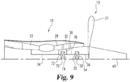
- a gearbox 50 is positioned in the gas turbine engine 10.
- the gearbox 50 can include a power input port 52 and a power outlet port 54.
- the power input port 52 is constructed to receive one or more input shafts to deliver power from one or more turbines of the gas turbine engine 10.
- the power outlet port 54 is constructed to couple one or more output shafts 56 to one or more power devices 15.
- Power devices 15 can include, but are not limited to turbofans, turboprops, electric generators, motor-generators, pusher props, and unducted fans.
- a low pressure turbine 32 can be coupled to a low pressure compressor 26 through a low pressure rotatable shaft 38.
- the low pressure turbine 32 can also be coupled to the power input port 52 of the gearbox 50 such that power in excess of that required to drive the low pressure compressor 26 can be delivered to the gearbox 50.
- An intermediate pressure turbine 30 can be coupled to an intermediate pressure compressor 24 through an intermediate pressure rotatable shaft 36.
- the intermediate pressure turbine 30 can also be coupled to the power input port 52 of the gearbox 50 such that power in excess of that required to drive the intermediate pressure compressor 24 can be delivered to the gearbox 50.
- a high pressure turbine 28 can be coupled to a high pressure compressor 22 through a rotatable shaft 34.
- the high pressure turbine 28 can also be coupled to the power input port 52 of the gearbox 50 such that power in excess of that required to drive the high pressure compressor 22 can be delivered to the gearbox 50.
- the gearbox 50 can be constructed to receive power from each independent shaft through a power inlet port 52. In one aspect of this disclosure, it is contemplated that some operating conditions of the gas turbine engine may require all of the power from one or more of the turbines 28, 30, 32 to be delivered to their respective one or more compressors 22, 24, 26 such that power input into the gearbox 50 comes from less than all of the turbines coupled to the gearbox 50.
- the gearbox 50 can receive and combine the power from each of the three shafts 34, 36, 38 and transmit the power through gear means to the output shaft 56.
- the output shaft 56 couples the power device 15 to the gearbox 50 through the power output port 54.
- the power output shaft 56 can be controlled by a gearbox controller (not shown) to drive the power device 15 to as close to peak efficiency as possible. In this manner, power is transmitted to the power device 15 such that thrust, fluid compression and/or electrical power may be generated with the power device 15 at a high efficiency.
- the gearbox 50 is positioned axially forward of the compressor section 14, but it should be understood that the gearbox 50 can be positioned in any desired location and still fall under the teachings of this disclosure.
- the gas turbine engine 10 includes a high pressure turbine 28 coupled to a high pressure compressor 22 through a high pressure shaft 34.
- An intermediate turbine 30 can be coupled to both an intermediate compressor 24 and a power input port 52 of a gearbox 50.
- a low pressure turbine 32 can be coupled to the power input port 52 of the gearbox 50.
- a power output port 54 of the gearbox 50 can be coupled to a power device 15 through two power output shafts 60 and 62.
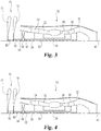
- the power device 15 includes a forward propeller 17 and an aft propeller 19.
- the forward propeller 17 can be driven by the low pressure turbine 32 through the gearbox 50 and the aft propeller 19 can be driven by power from the intermediate turbine 30 through the gearbox 50.
- the gearbox 50 is positioned axially forward of the compressor section 14 and the power device 15 is in the form of a pair of propellers, but it should be understood that the gearbox 50 can be positioned in any desired location and the power device 15 can be in other forms and still fall under the teachings of this disclosure.
- the gas turbine engine 10 includes a high pressure turbine 28 coupled to a high pressure compressor 22 through a high pressure shaft 34.
- An intermediate turbine 30 can be coupled to both an intermediate compressor 24 and a power input port 52 of a gearbox 50 through an intermediate shaft 36.
- a low pressure turbine 32 can be coupled to a power input port 52 of the gearbox 50,
- the power input port 52 of the gearbox 50 can be coupled to two independent turbines 30, 32 through the intermediate and low pressure shafts 36, 38 respectively.
- the power output port 54 of the gearbox 50 can be coupled to a. power device 15 through two output shafts 60 and 62.
- the power device 15 includes a forward propeller 17 and an aft propeller 19.
- the forward propeller 17 can be driven b - power from the intermediate turbine 32 through the gearbox 50 and the aft propeller 19 can be driven by power from the low pressure turbine 32 through the gearbox 50.
- the gearbox is positioned forward of the compressor section 14 and the power device 15 is in the form of a forward propeller 1 5 and an aft propeller 19, but it should be understood that the gearbox 50 can be positioned in any desired location and the power device 15 can be in other forms and still fall under the teachings of this disclosure.
- the gas turbine engine 10 includes a high pressure turbine 28 coupled to a high pressure compressor 22 through a high pressure shaft 34.
- the high pressure turbine 28 can also be coupled to a power input port 52 of a gearbox 50 through the high pressure shaft 34.
- a low pressure turbine 32 can be coupled directly to the power input port 52 of the gearbox 50 through a low pressure shaft 38.
- Power from the low pressure turbine shaft 38 and the high pressure turbine shaft 34 is delivered to the gearbox 50 and transmitted to a power device 15 through an output shaft 56 coupled to a power outlet port 54 of the gearbox 50.
- the gearbox 50 is positioned aft of the turbine section! 8 and the power device 15 is in the form of a pusher propeller 21, but it should be understood that the gearbox 50 can be positioned in any desired location and the power device 15 can be in other forms and still fall under the teachings of this disclosure.
- the gas turbine engine 10 includes a high pressure turbine 28 coupled to a. high pressure compressor 22 through a high pressure shaft 34.
- the high pressure turbine 28 can also be coupled to a power input port 72 of a second gearbox 70 through the high pressure shaft 34.
- a low pressure turbine 32 can be coupled to a power input port 52 of a. first gearbox 50 through a low pressure shaft 38,
- An output shaft 76 of the second gearbox 70 can be coupled to the low pressure shaft 38 such that power from the output shaft 76 of the second gearbox 70 can be combined with the power output of the low pressure turbine 38 and delivered to the first, gearbox 50.
- the combined power of the low pressure turbine 32 and the output of the second gearbox 70 can be transmitted through the first gear box 50 to the power output, port 54 of the first gearbox 50.
- An output shaft 56 can be coupled to the power output port 54 of the first gearbox 50 to drive a power device 15.
- the first gearbox 50 is positioned aft of the turbine section! 8
- the second gearbox 70 is positioned axially forward of the first gearbox 50 and the power device 15 is in the form of a pusher propeller 21, but it should be understood that the first gearbox 50 and the second gearbox 70 can be positioned in any desired location and the power device 15 can be in other forms and still fall under the teachings of this disclosure.
- the gas turbine engine 10 includes a high pressure turbine 28 coupled to a high pressure compressor 22 through a high pressure shaft 34.
- the high pressure turbine 28 can also be coupled to a power input port 72 of a second gearbox 70 through the high pressure shaft 34.
- a low pressure turbine can be coupled to a power input port 52 of a first gearbox 50 through a low pressure shaft 38.
- a power output shaft 56 can be coupled to a power output port 54 of the first gearbox 50.
- a power output shaft 76 of the second gearbox 70 can be coupled from the power outlet port 74 to the output shaft 56 of the first gearbox 50 such that power from the output shaft 76 of the second gearbox 70 can be combined with the power output of the first gearbox 50.
- the combined power output of the first and second gearboxes 50, 70 can be transmitted through the output shaft 56 of the first gearbox 50 to drive the power device 15.
- first gearbox 50 is positioned aft of the turbine section 18, the second gearbox 70 is positioned axially forward of the first gearbox 50 and the power device 15 is in the form of a pusher propeller 21 , but it should be understood that the first gearbox 50 and the second gearbox 70 can be positioned in any desired location and the power device 15 can be in other forms and still fall under the teachings of this disclosure,
- the gas turbine engine 10 includes a. high pressure turbine 28 coupled to a. high pressure compressor 22 through a high pressure shaft 34.
- the high pressure turbine 28 is also coupled to a power input port 72 of a second gearbox 70 through the high pressure shaft 34.
- a low pressure turbine 32 can be coupled to a power input port 52 of a first gearbox 50 to provide power thereto.
- An output shaft 76 can be coupled from an output port 74 of the second gearbox 70 to a. power input port 52 of a first gearbox 50 such that power from the output shaft 76 of the second gearbox 70 can be combined with the power input from the low pressure turbine 32.
- the combined power of the low pressure turbine 32 and the output of the second gearbox 70 can be transmitted to a power device 15 through an output shaft 56 coupled to a power output port 54 of the second gearbox 50,
- the first gearbox 50 is positioned aft of the turbine section] 8
- the second gearbox 70 is positioned axially forward of the first gearbox 50 and the power device 15 is in the form of a pusher propeller 21, but it should be understood that the first gearbox 50 and the second gearbox 70 can be positioned in any desired location and the power device 15 can be in other forms and still fall under the teachings of this disclosure..
- the gas turbine engine 10 includes a high pressure turbine 28 coupled to a high pressure compressor 22 through a high pressure shaft 34, The high pressure turbine 28 is also coupled to a power input port 72 of a second gearbox 70 through the high pressure shaft 34.
- An output shaft 76 of the second gearbox 70 can be coupled to a power output port 74 of the second gearbox 70.
- a low pressure turbine 32 can be coupled to the output shaft 76 of the second gearbox 70 through a low pressure shaft 38.
- the output shaft 76 carries power from the second gearbox 70 and the low pressure turbine 32 to a power input port 52 of first gearbox 50.
- the combined power of the low pressure turbine 32 and the second gearbox 70 can be transmitted through the first gearbox 50 to drive a power device 15 through an output shaft 56 coupled to a power output port 54 of the second gearbox 50.
- the first gearbox 50 is positioned aft of the turbine section 18, the second gearbox 70 is positioned axially forward of the first gearbox 50 and the power device 15 is in the form of a pusher propeller 21, but it should be understood that the first gearbox 50 and the second gearbox 70 can be positioned in any desired location and the power device 15 can be in other forms and still fall under the teachings of this disclosure.
Landscapes
- Engineering & Computer Science (AREA)
- Mechanical Engineering (AREA)
- General Engineering & Computer Science (AREA)
- Chemical & Material Sciences (AREA)
- Combustion & Propulsion (AREA)
- Aviation & Aerospace Engineering (AREA)
- Supercharger (AREA)
- Structures Of Non-Positive Displacement Pumps (AREA)
- Turbine Rotor Nozzle Sealing (AREA)
Claims (6)
- Gasturbinentriebwerk (10), umfassend:eine erste Wellenanordnung, welche eine erste Turbine (32) aufweist, die mit einem ersten Kompressor (26) durch eine erste Drehwelle (38) verbunden ist;eine zweite Wellenanordnung, welche eine zweite Turbine (30) aufweist, die mit einem zweiten Kompressor (24) durch eine zweite Drehwelle (36) verbunden ist;ein erstes Getriebe (50), welches einen ersten Leistungseingang (52), der mit jeweils einer der ersten und zweiten Welle (38, 36) gekoppelt ist und einen Leistungsausgang (54) aufweist, welcher mit mindestens einer Ausgangswelle (56) verbunden ist, wobei die Drehzahl der mindestens einen Ausgangswelle (56) niedriger ist als die Drehzahl jeder der ersten und zweiten Welle (38, 36) ist; undferner umfassend: eine dritte Wellenanordnung, welche eine dritte Turbine (28) aufweist, die mit einem dritten Kompressor (22) durch eine dritte Drehwelle (34) verbunden ist.
- Gasturbinentriebwerk (10) nach Anspruch 1, wobei:
die dritte Wellenanordnung mit dem Leistungseingang (52) des ersten Getriebes verbunden ist. - Gasturbinentriebwerk (10) nach Anspruch 1, wobei:
die Drehzahl der dritten Turbine (28) von der ersten und zweiten Turbine (32, 30) unabhängig ist. - Gasturbinentriebwerk (10) nach Anspruch 1, ferner umfassend:
ein zweites Getriebe (70), welches einen Leistungsausgang (74) aufweist, der mit einem des ersten Leistungseingangs (52) und des Leistungsausgangs (54) des ersten Getriebes (50) verbunden ist. - Gasturbinentriebwerk (10) nach Anspruch 4, wobei:
die dritte Turbine (28) mit dem zweiten Getriebe (70) verbunden ist. - Gasturbinentriebwerk (10) nach Anspruch 1, wobei:
der Leistungsausgang (52) des ersten Getriebes (50) mit mindestens einem von einem ummantelten Gebläse, einem nichtummantelten Gebläse, einem Propeller und einem elektrischen Generator verbunden ist.
Priority Applications (1)
| Application Number | Priority Date | Filing Date | Title |
|---|---|---|---|
| EP19198897.1A EP3604764B1 (de) | 2013-03-07 | 2013-12-19 | Mehrwellengasturbinentriebwerk |
Applications Claiming Priority (2)
| Application Number | Priority Date | Filing Date | Title |
|---|---|---|---|
| US201361774537P | 2013-03-07 | 2013-03-07 | |
| PCT/US2013/076523 WO2014137452A1 (en) | 2013-03-07 | 2013-12-19 | Multi-shaft gas turbine engine |
Related Child Applications (1)
| Application Number | Title | Priority Date | Filing Date |
|---|---|---|---|
| EP19198897.1A Division EP3604764B1 (de) | 2013-03-07 | 2013-12-19 | Mehrwellengasturbinentriebwerk |
Publications (2)
| Publication Number | Publication Date |
|---|---|
| EP2964921A1 EP2964921A1 (de) | 2016-01-13 |
| EP2964921B1 true EP2964921B1 (de) | 2019-10-16 |
Family
ID=49950052
Family Applications (2)
| Application Number | Title | Priority Date | Filing Date |
|---|---|---|---|
| EP13819137.4A Active EP2964921B1 (de) | 2013-03-07 | 2013-12-19 | Mehrwellengasturbinentriebwerk |
| EP19198897.1A Active EP3604764B1 (de) | 2013-03-07 | 2013-12-19 | Mehrwellengasturbinentriebwerk |
Family Applications After (1)
| Application Number | Title | Priority Date | Filing Date |
|---|---|---|---|
| EP19198897.1A Active EP3604764B1 (de) | 2013-03-07 | 2013-12-19 | Mehrwellengasturbinentriebwerk |
Country Status (3)
| Country | Link |
|---|---|
| US (2) | US9611788B2 (de) |
| EP (2) | EP2964921B1 (de) |
| WO (1) | WO2014137452A1 (de) |
Families Citing this family (30)
| Publication number | Priority date | Publication date | Assignee | Title |
|---|---|---|---|---|
| EP3961016A1 (de) * | 2013-02-13 | 2022-03-02 | Raytheon Technologies Corporation | Gasturbinenmotor mit getriebe architektur |
| US9752500B2 (en) * | 2013-03-14 | 2017-09-05 | Pratt & Whitney Canada Corp. | Gas turbine engine with transmission and method of adjusting rotational speed |
| US10144519B2 (en) * | 2014-10-24 | 2018-12-04 | United Technologies Corporation | Compressor bleed air supply for an aircraft environmental control system |
| US10151211B2 (en) * | 2015-01-10 | 2018-12-11 | Florida Turbine Technologies, Inc. | Apparatus and process for converting an aero gas turbine engine into an industrial gas turbine engine for electric power production |
| US11225913B2 (en) | 2015-02-19 | 2022-01-18 | Raytheon Technologies Corporation | Method of providing turbine engines with different thrust ratings |
| US20160245184A1 (en) * | 2015-02-19 | 2016-08-25 | United Technologies Corporation | Geared turbine engine |
| EP3109433B1 (de) * | 2015-06-19 | 2018-08-15 | Rolls-Royce Corporation | Motor, angetrieben durch sc02 mit unabhängigen wellen für verbrennungszykluselemente und antriebselemente |
| US10883424B2 (en) * | 2016-07-19 | 2021-01-05 | Pratt & Whitney Canada Corp. | Multi-spool gas turbine engine architecture |
| US11105200B2 (en) * | 2017-07-13 | 2021-08-31 | General Electric Company | Counter rotating power turbine with reduction gearbox |
| US11008883B2 (en) | 2017-09-20 | 2021-05-18 | General Electric Company | Turbomachine with a gearbox and integrated electric machine assembly |
| US10738692B2 (en) | 2017-09-20 | 2020-08-11 | Honeywell International Inc. | Distributed propulsion and electric power generation system |
| US10677159B2 (en) * | 2017-10-27 | 2020-06-09 | General Electric Company | Gas turbine engine including a dual-speed split compressor |
| GB201804128D0 (en) * | 2018-03-15 | 2018-05-02 | Rolls Royce Plc | Electrical power generator system |
| BE1026278B1 (fr) | 2018-05-15 | 2019-12-16 | Safran Aero Boosters Sa | Architecture de turbomachine a triple compresseur |
| US11156128B2 (en) | 2018-08-22 | 2021-10-26 | General Electric Company | Embedded electric machine |
| US20200080476A1 (en) * | 2018-09-12 | 2020-03-12 | Pratt & Whitney Canada Corp. | Spilt compressor system on multi-spool engine |
| US11041462B2 (en) | 2019-06-05 | 2021-06-22 | Raytheon Technologies Corporation | Hybrid turbofan with differential electrical and mechanical power transfer |
| US20200400036A1 (en) * | 2019-06-24 | 2020-12-24 | Pratt & Whitney Canada Corp. | Gas turbine engine system |
| CN112660396A (zh) | 2019-10-15 | 2021-04-16 | 通用电气公司 | 用于飞行器的可去除机身护罩 |
| US11506067B2 (en) | 2019-10-15 | 2022-11-22 | General Electric Company | Gas turbine engine with clutch assembly |
| US11286795B2 (en) | 2019-10-15 | 2022-03-29 | General Electric Company | Mount for an airfoil |
| US20210108576A1 (en) | 2019-10-15 | 2021-04-15 | General Electric Company | System and method for control for unducted engine |
| US11401824B2 (en) | 2019-10-15 | 2022-08-02 | General Electric Company | Gas turbine engine outlet guide vane assembly |
| DE102020207003A1 (de) | 2020-06-04 | 2021-12-09 | Robert Bosch Gesellschaft mit beschränkter Haftung | Rotorbaugruppe für einen Flugkörper und Flugkörper |
| US11643972B2 (en) * | 2020-06-15 | 2023-05-09 | Ge Avio S.R.L. | Turbomachines and epicyclic gear assemblies with symmetrical compound arrangement |
| US11725590B2 (en) * | 2020-10-22 | 2023-08-15 | General Electric Company | Turbomachine and gear assembly |
| US11428160B2 (en) | 2020-12-31 | 2022-08-30 | General Electric Company | Gas turbine engine with interdigitated turbine and gear assembly |
| US11939984B2 (en) * | 2021-04-29 | 2024-03-26 | The Boeing Company | Compressors having multi-speed gearboxes |
| IT202100015386A1 (it) * | 2021-06-11 | 2022-12-11 | Ge Avio Srl | Turbomacchine e gruppi ad ingranaggi epicicloidali con canali di lubrificazione |
| US11873767B2 (en) * | 2021-10-22 | 2024-01-16 | Ge Avio S.R.L. | Gearbox configurations for clockwise and counterclockwise propeller rotation |
Family Cites Families (19)
| Publication number | Priority date | Publication date | Assignee | Title |
|---|---|---|---|---|
| US4936748A (en) * | 1988-11-28 | 1990-06-26 | General Electric Company | Auxiliary power source in an unducted fan gas turbine engine |
| US5010729A (en) * | 1989-01-03 | 1991-04-30 | General Electric Company | Geared counterrotating turbine/fan propulsion system |
| US4916894A (en) * | 1989-01-03 | 1990-04-17 | General Electric Company | High bypass turbofan engine having a partially geared fan drive turbine |
| FR2761412B1 (fr) * | 1997-03-27 | 1999-04-30 | Snecma | Groupe turbopropulseur double corps a regulation isodrome |
| FR2864997B1 (fr) * | 2004-01-08 | 2006-04-28 | Snecma Moteurs | Turbomachine a turbine semi-liee entrainant un recepteur pilote de maniere a conserver une vitesse de rotation sensiblement constante |
| US7185496B2 (en) | 2004-07-12 | 2007-03-06 | Honeywell International, Inc. | Synchronizing stationary clutch of compression braking with a two spool gas turbine engine |
| US7726113B2 (en) | 2005-10-19 | 2010-06-01 | General Electric Company | Gas turbine engine assembly and methods of assembling same |
| US7905083B2 (en) | 2006-10-31 | 2011-03-15 | General Electric Company | Turbofan engine assembly and method of assembling same |
| US7882693B2 (en) | 2006-11-29 | 2011-02-08 | General Electric Company | Turbofan engine assembly and method of assembling same |
| US7788898B2 (en) * | 2006-12-06 | 2010-09-07 | General Electric Company | Variable coupling of turbofan engine spools via open differential gear set or simple planetary gear set for improved power extraction and engine operability, with torque coupling for added flexibility |
| US8015798B2 (en) | 2007-12-13 | 2011-09-13 | United Technologies Corporation | Geared counter-rotating gas turbofan engine |
| FR2940247B1 (fr) * | 2008-12-19 | 2011-01-21 | Snecma | Systeme d'helices contrarotatives entrainees par un train epicycloidal offrant une repartition de couple equilibree entre les deux helices |
| US8701381B2 (en) * | 2010-11-24 | 2014-04-22 | Rolls-Royce Corporation | Remote shaft driven open rotor propulsion system with electrical power generation |
| US9200592B2 (en) * | 2011-06-28 | 2015-12-01 | United Technologies Corporation | Mechanism for turbine engine start from low spool |
| US9021778B2 (en) * | 2011-06-28 | 2015-05-05 | United Technologies Corporation | Differential gear system with carrier drive |
| FR2979121B1 (fr) * | 2011-08-18 | 2013-09-06 | Snecma | Dispositif de transmission mecanique pour l'entrainement en rotation des helices contrarotatives d'un turbopropulseur a double helice. |
| EP2946103A1 (de) * | 2013-01-18 | 2015-11-25 | General Electric Company | Motor mit integriertem rückdrehungsantrieb und schaufellose turbine |
| WO2015006162A1 (en) * | 2013-07-12 | 2015-01-15 | United Technologies Corporation | Three spool geared turbofan with low pressure compressor drive gear system |
| WO2015031143A1 (en) * | 2013-08-29 | 2015-03-05 | United Technologies Corporation | Three spool geared turbofan with low pressure compressor drive gear system and mechanical controller |
-
2013
- 2013-12-19 EP EP13819137.4A patent/EP2964921B1/de active Active
- 2013-12-19 EP EP19198897.1A patent/EP3604764B1/de active Active
- 2013-12-19 WO PCT/US2013/076523 patent/WO2014137452A1/en active Application Filing
- 2013-12-26 US US14/140,964 patent/US9611788B2/en active Active
-
2017
- 2017-02-15 US US15/433,614 patent/US10738710B2/en active Active
Non-Patent Citations (1)
| Title |
|---|
| None * |
Also Published As
| Publication number | Publication date |
|---|---|
| US9611788B2 (en) | 2017-04-04 |
| EP2964921A1 (de) | 2016-01-13 |
| US10738710B2 (en) | 2020-08-11 |
| US20140250860A1 (en) | 2014-09-11 |
| EP3604764A1 (de) | 2020-02-05 |
| EP3604764B1 (de) | 2023-04-19 |
| US20170159571A1 (en) | 2017-06-08 |
| WO2014137452A1 (en) | 2014-09-12 |
Similar Documents
| Publication | Publication Date | Title |
|---|---|---|
| EP2964921B1 (de) | Mehrwellengasturbinentriebwerk | |
| EP3361122B1 (de) | Planetengetriebe für gasturbinenmotor | |
| US11300007B2 (en) | Planetary gearbox having compliant journal bearings | |
| US11041443B2 (en) | Multi-spool gas turbine engine architecture | |
| EP2553251B1 (de) | Adaptives lüftersystem für einen turbofanlüfter mit variablem zyklus | |
| EP3339606B1 (de) | Gasturbinenmotor mit umgekehrtem fluss | |
| US6082967A (en) | Constant-speed twin spool turboprop unit | |
| EP2992198B1 (de) | Zwei wellen turbomaschine | |
| US9328667B2 (en) | Systems and methods for changing a speed of a compressor boost stage in a gas turbine | |
| EP3282093A1 (de) | Getriebeturbolüfter mit niederdruckleistungsextraktion | |
| EP2452879B1 (de) | Antriebssystem für ein Luftfahrzeug | |
| EP3257753B1 (de) | Reduktionsgetriebevorrichtung für ein flugzeugtriebwerk | |
| EP3020953B1 (de) | Gasturbinenmotor | |
| EP3859134A1 (de) | Planetengetriebe für gasturbinenmotor | |
| EP3096023B1 (de) | Gasturbine mit einspritzdüse für verdichterschaufelspitze | |
| EP3800342A1 (de) | Überlagerungsgetriebe für motorperformance | |
| EP3736423A1 (de) | Hybrides elektrisches flugzeugantriebssystem | |
| WO2013130296A1 (en) | Gas turbine engine driving multiple fans | |
| EP3327276B1 (de) | Gasturbinentriebwerk | |
| US20170363043A1 (en) | Gas turbine engine | |
| US10378439B2 (en) | Gas turbine engine with variable speed turbines | |
| EP3569507A1 (de) | Flugzeugantriebssystem |
Legal Events
| Date | Code | Title | Description |
|---|---|---|---|
| PUAI | Public reference made under article 153(3) epc to a published international application that has entered the european phase |
Free format text: ORIGINAL CODE: 0009012 |
|
| 17P | Request for examination filed |
Effective date: 20150827 |
|
| AK | Designated contracting states |
Kind code of ref document: A1 Designated state(s): AL AT BE BG CH CY CZ DE DK EE ES FI FR GB GR HR HU IE IS IT LI LT LU LV MC MK MT NL NO PL PT RO RS SE SI SK SM TR |
|
| AX | Request for extension of the european patent |
Extension state: BA ME |
|
| DAX | Request for extension of the european patent (deleted) | ||
| STAA | Information on the status of an ep patent application or granted ep patent |
Free format text: STATUS: EXAMINATION IS IN PROGRESS |
|
| 17Q | First examination report despatched |
Effective date: 20170906 |
|
| GRAP | Despatch of communication of intention to grant a patent |
Free format text: ORIGINAL CODE: EPIDOSNIGR1 |
|
| STAA | Information on the status of an ep patent application or granted ep patent |
Free format text: STATUS: GRANT OF PATENT IS INTENDED |
|
| INTG | Intention to grant announced |
Effective date: 20190425 |
|
| GRAS | Grant fee paid |
Free format text: ORIGINAL CODE: EPIDOSNIGR3 |
|
| GRAA | (expected) grant |
Free format text: ORIGINAL CODE: 0009210 |
|
| STAA | Information on the status of an ep patent application or granted ep patent |
Free format text: STATUS: THE PATENT HAS BEEN GRANTED |
|
| AK | Designated contracting states |
Kind code of ref document: B1 Designated state(s): AL AT BE BG CH CY CZ DE DK EE ES FI FR GB GR HR HU IE IS IT LI LT LU LV MC MK MT NL NO PL PT RO RS SE SI SK SM TR |
|
| REG | Reference to a national code |
Ref country code: GB Ref legal event code: FG4D |
|
| REG | Reference to a national code |
Ref country code: CH Ref legal event code: EP |
|
| REG | Reference to a national code |
Ref country code: DE Ref legal event code: R096 Ref document number: 602013061830 Country of ref document: DE |
|
| REG | Reference to a national code |
Ref country code: IE Ref legal event code: FG4D |
|
| REG | Reference to a national code |
Ref country code: AT Ref legal event code: REF Ref document number: 1191478 Country of ref document: AT Kind code of ref document: T Effective date: 20191115 |
|
| REG | Reference to a national code |
Ref country code: NL Ref legal event code: MP Effective date: 20191016 |
|
| REG | Reference to a national code |
Ref country code: LT Ref legal event code: MG4D |
|
| REG | Reference to a national code |
Ref country code: AT Ref legal event code: MK05 Ref document number: 1191478 Country of ref document: AT Kind code of ref document: T Effective date: 20191016 |
|
| PG25 | Lapsed in a contracting state [announced via postgrant information from national office to epo] |
Ref country code: FI Free format text: LAPSE BECAUSE OF FAILURE TO SUBMIT A TRANSLATION OF THE DESCRIPTION OR TO PAY THE FEE WITHIN THE PRESCRIBED TIME-LIMIT Effective date: 20191016 Ref country code: BG Free format text: LAPSE BECAUSE OF FAILURE TO SUBMIT A TRANSLATION OF THE DESCRIPTION OR TO PAY THE FEE WITHIN THE PRESCRIBED TIME-LIMIT Effective date: 20200116 Ref country code: NO Free format text: LAPSE BECAUSE OF FAILURE TO SUBMIT A TRANSLATION OF THE DESCRIPTION OR TO PAY THE FEE WITHIN THE PRESCRIBED TIME-LIMIT Effective date: 20200116 Ref country code: PL Free format text: LAPSE BECAUSE OF FAILURE TO SUBMIT A TRANSLATION OF THE DESCRIPTION OR TO PAY THE FEE WITHIN THE PRESCRIBED TIME-LIMIT Effective date: 20191016 Ref country code: NL Free format text: LAPSE BECAUSE OF FAILURE TO SUBMIT A TRANSLATION OF THE DESCRIPTION OR TO PAY THE FEE WITHIN THE PRESCRIBED TIME-LIMIT Effective date: 20191016 Ref country code: GR Free format text: LAPSE BECAUSE OF FAILURE TO SUBMIT A TRANSLATION OF THE DESCRIPTION OR TO PAY THE FEE WITHIN THE PRESCRIBED TIME-LIMIT Effective date: 20200117 Ref country code: LT Free format text: LAPSE BECAUSE OF FAILURE TO SUBMIT A TRANSLATION OF THE DESCRIPTION OR TO PAY THE FEE WITHIN THE PRESCRIBED TIME-LIMIT Effective date: 20191016 Ref country code: ES Free format text: LAPSE BECAUSE OF FAILURE TO SUBMIT A TRANSLATION OF THE DESCRIPTION OR TO PAY THE FEE WITHIN THE PRESCRIBED TIME-LIMIT Effective date: 20191016 Ref country code: LV Free format text: LAPSE BECAUSE OF FAILURE TO SUBMIT A TRANSLATION OF THE DESCRIPTION OR TO PAY THE FEE WITHIN THE PRESCRIBED TIME-LIMIT Effective date: 20191016 Ref country code: SE Free format text: LAPSE BECAUSE OF FAILURE TO SUBMIT A TRANSLATION OF THE DESCRIPTION OR TO PAY THE FEE WITHIN THE PRESCRIBED TIME-LIMIT Effective date: 20191016 Ref country code: AT Free format text: LAPSE BECAUSE OF FAILURE TO SUBMIT A TRANSLATION OF THE DESCRIPTION OR TO PAY THE FEE WITHIN THE PRESCRIBED TIME-LIMIT Effective date: 20191016 Ref country code: PT Free format text: LAPSE BECAUSE OF FAILURE TO SUBMIT A TRANSLATION OF THE DESCRIPTION OR TO PAY THE FEE WITHIN THE PRESCRIBED TIME-LIMIT Effective date: 20200217 |
|
| PG25 | Lapsed in a contracting state [announced via postgrant information from national office to epo] |
Ref country code: IS Free format text: LAPSE BECAUSE OF FAILURE TO SUBMIT A TRANSLATION OF THE DESCRIPTION OR TO PAY THE FEE WITHIN THE PRESCRIBED TIME-LIMIT Effective date: 20200224 Ref country code: RS Free format text: LAPSE BECAUSE OF FAILURE TO SUBMIT A TRANSLATION OF THE DESCRIPTION OR TO PAY THE FEE WITHIN THE PRESCRIBED TIME-LIMIT Effective date: 20191016 Ref country code: HR Free format text: LAPSE BECAUSE OF FAILURE TO SUBMIT A TRANSLATION OF THE DESCRIPTION OR TO PAY THE FEE WITHIN THE PRESCRIBED TIME-LIMIT Effective date: 20191016 |
|
| PG25 | Lapsed in a contracting state [announced via postgrant information from national office to epo] |
Ref country code: AL Free format text: LAPSE BECAUSE OF FAILURE TO SUBMIT A TRANSLATION OF THE DESCRIPTION OR TO PAY THE FEE WITHIN THE PRESCRIBED TIME-LIMIT Effective date: 20191016 |
|
| REG | Reference to a national code |
Ref country code: DE Ref legal event code: R097 Ref document number: 602013061830 Country of ref document: DE |
|
| PG2D | Information on lapse in contracting state deleted |
Ref country code: IS |
|
| PG25 | Lapsed in a contracting state [announced via postgrant information from national office to epo] |
Ref country code: DK Free format text: LAPSE BECAUSE OF FAILURE TO SUBMIT A TRANSLATION OF THE DESCRIPTION OR TO PAY THE FEE WITHIN THE PRESCRIBED TIME-LIMIT Effective date: 20191016 Ref country code: EE Free format text: LAPSE BECAUSE OF FAILURE TO SUBMIT A TRANSLATION OF THE DESCRIPTION OR TO PAY THE FEE WITHIN THE PRESCRIBED TIME-LIMIT Effective date: 20191016 Ref country code: RO Free format text: LAPSE BECAUSE OF FAILURE TO SUBMIT A TRANSLATION OF THE DESCRIPTION OR TO PAY THE FEE WITHIN THE PRESCRIBED TIME-LIMIT Effective date: 20191016 Ref country code: CZ Free format text: LAPSE BECAUSE OF FAILURE TO SUBMIT A TRANSLATION OF THE DESCRIPTION OR TO PAY THE FEE WITHIN THE PRESCRIBED TIME-LIMIT Effective date: 20191016 Ref country code: IS Free format text: LAPSE BECAUSE OF FAILURE TO SUBMIT A TRANSLATION OF THE DESCRIPTION OR TO PAY THE FEE WITHIN THE PRESCRIBED TIME-LIMIT Effective date: 20200216 |
|
| REG | Reference to a national code |
Ref country code: CH Ref legal event code: PL |
|
| PLBE | No opposition filed within time limit |
Free format text: ORIGINAL CODE: 0009261 |
|
| STAA | Information on the status of an ep patent application or granted ep patent |
Free format text: STATUS: NO OPPOSITION FILED WITHIN TIME LIMIT |
|
| REG | Reference to a national code |
Ref country code: BE Ref legal event code: MM Effective date: 20191231 |
|
| PG25 | Lapsed in a contracting state [announced via postgrant information from national office to epo] |
Ref country code: MC Free format text: LAPSE BECAUSE OF FAILURE TO SUBMIT A TRANSLATION OF THE DESCRIPTION OR TO PAY THE FEE WITHIN THE PRESCRIBED TIME-LIMIT Effective date: 20191016 Ref country code: SK Free format text: LAPSE BECAUSE OF FAILURE TO SUBMIT A TRANSLATION OF THE DESCRIPTION OR TO PAY THE FEE WITHIN THE PRESCRIBED TIME-LIMIT Effective date: 20191016 Ref country code: IT Free format text: LAPSE BECAUSE OF FAILURE TO SUBMIT A TRANSLATION OF THE DESCRIPTION OR TO PAY THE FEE WITHIN THE PRESCRIBED TIME-LIMIT Effective date: 20191016 Ref country code: SM Free format text: LAPSE BECAUSE OF FAILURE TO SUBMIT A TRANSLATION OF THE DESCRIPTION OR TO PAY THE FEE WITHIN THE PRESCRIBED TIME-LIMIT Effective date: 20191016 |
|
| 26N | No opposition filed |
Effective date: 20200717 |
|
| GBPC | Gb: european patent ceased through non-payment of renewal fee |
Effective date: 20200116 |
|
| PG25 | Lapsed in a contracting state [announced via postgrant information from national office to epo] |
Ref country code: LU Free format text: LAPSE BECAUSE OF NON-PAYMENT OF DUE FEES Effective date: 20191219 Ref country code: IE Free format text: LAPSE BECAUSE OF NON-PAYMENT OF DUE FEES Effective date: 20191219 Ref country code: GB Free format text: LAPSE BECAUSE OF NON-PAYMENT OF DUE FEES Effective date: 20200116 |
|
| PG25 | Lapsed in a contracting state [announced via postgrant information from national office to epo] |
Ref country code: BE Free format text: LAPSE BECAUSE OF NON-PAYMENT OF DUE FEES Effective date: 20191231 Ref country code: SI Free format text: LAPSE BECAUSE OF FAILURE TO SUBMIT A TRANSLATION OF THE DESCRIPTION OR TO PAY THE FEE WITHIN THE PRESCRIBED TIME-LIMIT Effective date: 20191016 Ref country code: CH Free format text: LAPSE BECAUSE OF NON-PAYMENT OF DUE FEES Effective date: 20191231 Ref country code: LI Free format text: LAPSE BECAUSE OF NON-PAYMENT OF DUE FEES Effective date: 20191231 |
|
| PG25 | Lapsed in a contracting state [announced via postgrant information from national office to epo] |
Ref country code: CY Free format text: LAPSE BECAUSE OF FAILURE TO SUBMIT A TRANSLATION OF THE DESCRIPTION OR TO PAY THE FEE WITHIN THE PRESCRIBED TIME-LIMIT Effective date: 20191016 |
|
| PG25 | Lapsed in a contracting state [announced via postgrant information from national office to epo] |
Ref country code: MT Free format text: LAPSE BECAUSE OF FAILURE TO SUBMIT A TRANSLATION OF THE DESCRIPTION OR TO PAY THE FEE WITHIN THE PRESCRIBED TIME-LIMIT Effective date: 20191016 Ref country code: HU Free format text: LAPSE BECAUSE OF FAILURE TO SUBMIT A TRANSLATION OF THE DESCRIPTION OR TO PAY THE FEE WITHIN THE PRESCRIBED TIME-LIMIT; INVALID AB INITIO Effective date: 20131219 |
|
| PG25 | Lapsed in a contracting state [announced via postgrant information from national office to epo] |
Ref country code: TR Free format text: LAPSE BECAUSE OF FAILURE TO SUBMIT A TRANSLATION OF THE DESCRIPTION OR TO PAY THE FEE WITHIN THE PRESCRIBED TIME-LIMIT Effective date: 20191016 |
|
| PG25 | Lapsed in a contracting state [announced via postgrant information from national office to epo] |
Ref country code: MK Free format text: LAPSE BECAUSE OF FAILURE TO SUBMIT A TRANSLATION OF THE DESCRIPTION OR TO PAY THE FEE WITHIN THE PRESCRIBED TIME-LIMIT Effective date: 20191016 |
|
| P01 | Opt-out of the competence of the unified patent court (upc) registered |
Effective date: 20230528 |
|
| PGFP | Annual fee paid to national office [announced via postgrant information from national office to epo] |
Ref country code: FR Payment date: 20231226 Year of fee payment: 11 |
|
| PGFP | Annual fee paid to national office [announced via postgrant information from national office to epo] |
Ref country code: DE Payment date: 20231227 Year of fee payment: 11 |