EP2964904B1 - Gas turbine engine - Google Patents
Gas turbine engine Download PDFInfo
- Publication number
- EP2964904B1 EP2964904B1 EP13808356.3A EP13808356A EP2964904B1 EP 2964904 B1 EP2964904 B1 EP 2964904B1 EP 13808356 A EP13808356 A EP 13808356A EP 2964904 B1 EP2964904 B1 EP 2964904B1
- Authority
- EP
- European Patent Office
- Prior art keywords
- stage
- rotor
- rotating
- gas turbine
- turbine engine
- Prior art date
- Legal status (The legal status is an assumption and is not a legal conclusion. Google has not performed a legal analysis and makes no representation as to the accuracy of the status listed.)
- Active
Links
- 238000004891 communication Methods 0.000 claims description 11
- 239000012530 fluid Substances 0.000 claims description 11
- 239000007789 gas Substances 0.000 description 21
- 238000002485 combustion reaction Methods 0.000 description 6
- 238000012986 modification Methods 0.000 description 3
- 230000004048 modification Effects 0.000 description 3
- 238000004804 winding Methods 0.000 description 3
- 238000005516 engineering process Methods 0.000 description 2
- 230000004075 alteration Effects 0.000 description 1
- 238000004200 deflagration Methods 0.000 description 1
- 238000005474 detonation Methods 0.000 description 1
- 239000000284 extract Substances 0.000 description 1
- 239000000446 fuel Substances 0.000 description 1
- 230000001737 promoting effect Effects 0.000 description 1
- 238000011144 upstream manufacturing Methods 0.000 description 1
Images

Classifications
-
- H—ELECTRICITY
- H02—GENERATION; CONVERSION OR DISTRIBUTION OF ELECTRIC POWER
- H02K—DYNAMO-ELECTRIC MACHINES
- H02K7/00—Arrangements for handling mechanical energy structurally associated with dynamo-electric machines, e.g. structural association with mechanical driving motors or auxiliary dynamo-electric machines
- H02K7/18—Structural association of electric generators with mechanical driving motors, e.g. with turbines
- H02K7/1807—Rotary generators
- H02K7/1823—Rotary generators structurally associated with turbines or similar engines
-
- F—MECHANICAL ENGINEERING; LIGHTING; HEATING; WEAPONS; BLASTING
- F01—MACHINES OR ENGINES IN GENERAL; ENGINE PLANTS IN GENERAL; STEAM ENGINES
- F01D—NON-POSITIVE DISPLACEMENT MACHINES OR ENGINES, e.g. STEAM TURBINES
- F01D15/00—Adaptations of machines or engines for special use; Combinations of engines with devices driven thereby
- F01D15/10—Adaptations for driving, or combinations with, electric generators
-
- F—MECHANICAL ENGINEERING; LIGHTING; HEATING; WEAPONS; BLASTING
- F02—COMBUSTION ENGINES; HOT-GAS OR COMBUSTION-PRODUCT ENGINE PLANTS
- F02K—JET-PROPULSION PLANTS
- F02K3/00—Plants including a gas turbine driving a compressor or a ducted fan
- F02K3/02—Plants including a gas turbine driving a compressor or a ducted fan in which part of the working fluid by-passes the turbine and combustion chamber
-
- F—MECHANICAL ENGINEERING; LIGHTING; HEATING; WEAPONS; BLASTING
- F05—INDEXING SCHEMES RELATING TO ENGINES OR PUMPS IN VARIOUS SUBCLASSES OF CLASSES F01-F04
- F05D—INDEXING SCHEME FOR ASPECTS RELATING TO NON-POSITIVE-DISPLACEMENT MACHINES OR ENGINES, GAS-TURBINES OR JET-PROPULSION PLANTS
- F05D2220/00—Application
- F05D2220/70—Application in combination with
- F05D2220/76—Application in combination with an electrical generator
Definitions
- the present disclosure relates to gas turbine engines, and more particularly, to gas turbine engines equipped with electrical machines for generating electrical power.
- One embodiment of the present disclosure is a unique gas turbine engine having an electrical machine for generating electrical power.
- Other embodiments include other unique gas turbine engines having electrical machines for generating electrical power.
- gas turbine engine 10 is an aircraft propulsion power plant.
- gas turbine engine 10 may be a land-based or marine engine.
- gas turbine engine 10 is a multi-spool turbofan engine.
- gas turbine engine 10 may take other forms, and may be, for example, a turboshaft engine, a turbojet engine, a turboprop engine, or a combined cycle engine having a single spool or multiple spools.
- gas turbine engine 10 includes a fan system 12, a bypass duct 14, a compressor 16, a diffuser 18, a combustor 20, a turbine 22, an electrical machine 24, a discharge duct 26 and a nozzle system 28.
- Bypass duct 14 and compressor 16 are in fluid communication with fan system 12.
- Diffuser 18 is in fluid communication with compressor 16.
- Combustor 20 is fluidly disposed between compressor 16 and turbine 22.
- combustor 20 includes a combustion liner (not shown) that contains a continuous combustion process.
- combustor 20 may take other forms, and may be, for example and without limitation, a wave rotor combustion system, a rotary valve combustion system or a slinger combustion system, and may employ deflagration and/or detonation combustion processes.
- Fan system 12 includes a fan rotor system 30.
- fan rotor system 30 includes one or more rotors (not shown) that are powered by turbine 22.
- fan rotor system 30 is a cold section rotating stage in the form of a single rotating fan blade stage having a wheel 32 and a plurality of fan blades 34 that are circumferentially surrounded by a fan shroud 36.
- shroud 36 is configured to retain one or more blades 34 within engine 10 during a blade-off event. In other embodiments, shroud 36 may not be so configured.
- Bypass duct 14 is operative to transmit a bypass flow generated by fan system 12 to nozzle 28.
- Compressor 16 includes a compressor rotor system 38, which are also referred to as cold section stages.
- compressor rotor system 38 includes one or more rotors (not shown) that are powered by turbine 22.
- Each compressor rotor includes a plurality of rows of compressor blades (not shown) that are alternatingly interspersed with rows of compressor vanes (not shown).
- the compressor blades are circumferentially surrounded by shrouds, e.g., in the form of blade tracks mounted on or formed as part of one or more compressor cases (not shown).
- Turbine 22 includes a turbine rotor system 40.
- turbine rotor system 40 includes one or more rotors (not shown) operative to drive fan rotor system 30 and compressor rotor system 38.
- Each turbine rotor includes a plurality of turbine blades (not shown) that are alternatingly interspersed with rows of turbine vanes (not shown).
- the turbine blades are circumferentially surrounded by shrouds, e.g., in the form of blade tracks mounted on or formed as part of one or more compressor cases (not shown).
- Electrical machine 24 is configured to generate electrical power. In one form, electrical machine 24 is disposed in (or adjacent to) fan system 12. In other embodiments, electrical machine 24 may be disposed within (or adjacent to) compressor 16. In various embodiments, electrical machine 24 may be configured as a generator, an alternator or any other type of electrical machine that is configured to generate electrical power.
- Turbine rotor system 40 is drivingly coupled to compressor rotor system 38 and fan rotor system 30 via a shafting system 42.
- shafting system 42 includes a plurality of shafts that may rotate at the same or different speeds and directions. In some embodiments, only a single shaft may be employed.
- Turbine 22 is operative to discharge an engine 10 core flow to nozzle 28.
- fan rotor system 30, compressor rotor system 38, turbine rotor system 40 and shafting system 42 rotate about an engine centerline 46. In other embodiments, all or parts of fan rotor system 30, compressor rotor system 38, turbine rotor system 40 and shafting system 42 may rotate about one or more other axes of rotation in addition to or in place of engine centerline 46.
- Discharge duct 26 extends between a discharge portion 48 of turbine 22 and engine nozzle 28. Discharge duct 26 is operative to direct bypass flow and core flow from a bypass duct discharge portion 44 and turbine discharge portion 48, respectively, into nozzle system 28. In some embodiments, discharge duct 26 may be considered a part of nozzle 28. Nozzle 28 is in fluid communication with fan system 12 and turbine 22. Nozzle 28 is operative to receive the bypass flow from fan system 12 via bypass duct 14, and to receive the core flow from turbine 22, and to discharge both as an engine exhaust flow, e.g., a thrust-producing flow. In other embodiments, other nozzle arrangements may be employed, including separate nozzles for each of the core flow and the bypass flow.
- air is drawn into the inlet of fan 12 and pressurized by fan 12.
- Some of the air pressurized by fan 12 is directed into compressor 16 as core flow, and some of the pressurized air is directed into bypass duct 14 as bypass flow, and is discharged into nozzle 28 via discharge duct 26.
- Compressor 16 further pressurizes the portion of the air received therein from fan 12, which is then discharged into diffuser 18.
- Diffuser 18 reduces the velocity of the pressurized air, and directs the diffused core airflow into combustor 20.
- Fuel is mixed with the pressurized air in combustor 20, which is then combusted.
- the hot gases exiting combustor 20 are directed into turbine 22, which extracts energy in the form of mechanical shaft power sufficient to drive fan system 12 and compressor 16 via shafting system 42.
- the core flow exiting turbine 22 is directed along an engine tail cone 50 and into discharge duct 26, along with the bypass flow from bypass duct 14.
- Discharge duct 26 is configured to receive the bypass flow and the core flow, and to discharge both as an engine exhaust flow, e.g., for providing thrust, such as for aircraft propulsion.
- Electrical machine 24 includes a stator 60 and a rotor 62, each of which includes electrical generating components.
- stator 60 and rotor 62 are disposed adjacent to fan blades 34.
- stator 60 and rotor 62 may be positioned adjacent to compressor blades in addition to or in place of fan blades 34.
- stator 60 is positioned adjacent to shroud 36. In other embodiments, stator 60 may be positioned within shroud 36.
- Stator 60 includes as an electrical generating component an armature component 64.
- armature component 64 is an armature winding.
- armature component 64 may be in the form of a continuous ring extending circumferentially around rotor 62, or may be formed of discreet armature elements, e.g., windings, spaced apart circumferentially around rotor 62. In other embodiments, armature component 64 may take other forms.
- Rotor 62 includes a hub 66, a plurality of struts 68, a plurality of rotor tips 70 and a plurality of electrical generating components in the form of field components 72.
- rotor 62 is configured to rotate the same speed as fan rotor stage 30 during the operation of engine 10. In other embodiments, rotor 62 may be configured to rotate at a different speed than fan rotor stage 30.
- hub 66 is formed integrally with wheel 32 as an extension of wheel 32. In other embodiments, hub 66 may be formed separately from wheel 32 and be coupled to wheel 32.
- Struts 68 extend radially outward from hub 66, culminating at rotor tips 70. Struts 68 are spaced apart circumferentially. Struts 68 are configured to support field components 72. In one form, each strut 68 is configured to support and radially retain a single field component 72 during the operation of engine 10. In other embodiments, each strut 68 may support and retain more than one field component 72. In one form, each strut 68 is positioned adjacent to a blade 34. In other embodiments, struts 68 may be positioned adjacent to a compressor blade in addition to or in place of blade 34.
- struts 68 are configured to rotate with blades 34, e.g., such that the position of each strut 68 relative to an adjacent blade 34 is maintained during the operation of engine 10.
- struts 68 are positioned downstream of blades 34, which in some embodiments may reduce or eliminate aerodynamic losses associated with struts 68.
- Rotor tips 70 are positioned proximate to stator 60 in an axial position different from that of blades 34. In one form, rotor tips 70 are positioned downstream of fan blades 34. In other embodiments, rotor tips 70 may be positioned upstream of fan blades 34.
- Field components 72 are disposed adjacent to stator 60. In one form, field components 72 are in the form of magnets. In other embodiments, field components 72 may take other forms. In a particular form, field components 72 are in the form of permanent magnets. In other embodiments, other types of magnets may be employed as field components 72 in addition to or in place of permanent magnets, for example and without limitation, electromagnets.
- Rotor 62 and stator 60 are configured to form a gap 74 therebetween, in particular, between field component 72 and armature component 64.
- electrical machine 24 is cooled by the airflow pressurized by fan rotor stage 30 that passes through gap 74.
- electrical machine 24 may be cooled by other means in addition to or in place of the airflow pressurized by fan rotor stage 30 passing through gap 74.
- Embodiments of the present disclosure include a gas turbine engine, comprising: a cold section stage being at least one of a fan blade stage and a compressor blade stage, wherein the cold section stage includes plurality of blades and a shroud circumferentially surrounding the plurality of blades; a combustor in fluid communication with the at least one of the fan blade stage and the compressor blade stage; a turbine in fluid communication with the combustor; and an electrical machine configured to generate electrical power, wherein the electrical machine includes a stator and a rotor; wherein the stator is positioned adjacent to or within the shroud; and wherein the rotor includes a rotor tip positioned proximate to the stator and in a different axial location than the blades.
- the stator includes an armature component positioned adjacent to or within the shroud; and wherein the rotor tip includes a field component positioned proximate to the stator.
- the armature component is an armature winding; and wherein the field component is a magnet.
- the rotor includes a hub and a strut extending from the hub, wherein the strut is configured to support the field component.
- the strut is positioned adjacent to a blade of the cold section stage.
- the strut is positioned downstream of the blade.
- the strut is configured to rotate with the blade.
- the cold section stage includes a wheel; wherein the rotor includes a hub and a strut extending from the hub; wherein the strut is configured to support the field component; and wherein the hub is coupled to the wheel or is formed as an extension of the wheel.
- the rotor is configured to operate at the same rotational speed as the cold section stage during operation of the gas turbine engine.
- the electrical machine is cooled by airflow pressurized by the cold section stage.
- the rotor and the stator are configured to form a gap between the rotor and stator; and wherein the electrical machine is cooled by the airflow passing through the gap.
- Embodiments of the present disclosure include a gas turbine engine, comprising: at least one of a rotating fan stage and a rotating compressor stage; a combustor in fluid communication with the at least one of the rotating fan stage and the rotating compressor stage; at least one rotating turbine stage in fluid communication with the combustor; and an electrical machine configured to generate electrical power, wherein the electrical machine includes a stator and a rotor; wherein the at least one of the rotating fan stage and the rotating compressor stage include a shroud circumferentially surrounding a plurality of blades of the at least one of the rotating fan stage and the rotating compressor stage ; and wherein the stator is positioned adjacent to or within the shroud; and wherein the rotor includes a rotor tip positioned proximate to the stator and in a different axial location than the blades.
- the stator includes an armature component positioned adjacent to or within the shroud; and wherein the rotor tip includes a field component positioned proximate to the stator.
- the at least one of the rotating fan stage and the rotating compressor stage includes a wheel; wherein the rotor includes a hub and a strut extending from the hub; wherein the strut is configured as part of the rotor; and wherein the hub is coupled to the wheel or is formed as an extension of the wheel.
- the rotor is configured to operate at the same rotational speed as the at least one of the rotating fan stage and the rotating compressor stage during operation of the gas turbine engine.
- the rotor includes a hub and a strut extending from the hub.
- the strut is positioned adjacent to a blade of the at least one of the rotating fan stage and the rotating compressor stage
- the strut is configured to rotate with the blade.
- Embodiments of the present disclosure include a gas turbine engine, comprising: at least one of a rotating fan stage and a rotating compressor stage; a combustor in fluid communication with the at least one of the rotating fan stage and the rotating compressor stage; at least one rotating turbine stage in fluid communication with the combustor; and means for generating electrical power disposed adjacent to the at least one of the rotating fan stage and the rotating compressor stage.
- the means for generating electrical power includes a stator, a rotor having struts and first electrical generating components disposed at tips of the struts; wherein the struts are positioned adjacent to and configured to rotate with the at least one of the rotating fan stage and the rotating compressor stage ; wherein the at least one of the rotating fan stage and the rotating compressor stage include a shroud; wherein the stator includes second electrical generating components positioned adjacent to or within the shroud.
Description
- The present disclosure relates to gas turbine engines, and more particularly, to gas turbine engines equipped with electrical machines for generating electrical power.
- Gas turbine engines with generator or alternator systems remain an area of interest. Some existing systems have various shortcomings, drawbacks, and disadvantages relative to certain applications. Therefore, there remains a need for further contributions in this area of technology.
- According to the present disclosure, there is provided the use of an electrical machine in a gas turbine engine and a gas turbine engine having an electrical machine, as set forth in the appended claims. Relevant background art can be found in
EP 2280150 A1 ,US 4253031 A ,US2008/0265580 A1 ,US2008/0120980 A1 andUS2012/0133150 A1 . - One embodiment of the present disclosure is a unique gas turbine engine having an electrical machine for generating electrical power. Other embodiments include other unique gas turbine engines having electrical machines for generating electrical power. Further embodiments, forms, features, aspects, benefits, and advantages of the present application will become apparent from the description and figures provided herewith.
- The description herein makes reference to the accompanying drawings wherein like reference numerals refer to like parts throughout the several views, and wherein:
-
FIG. 1 schematically illustrates some aspects of a non-limiting example of a gas turbine engine in accordance with an embodiment of the present disclosure. -
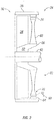
FIG. 2 schematically illustrates some aspects of a non-limiting example of an electrical machine for generating electrical power in accordance with an embodiment of the present disclosure. - For purposes of promoting an understanding of the principles of the disclosure, reference will now be made to the embodiments illustrated in the drawings, and specific language will be used to describe the same. It will nonetheless be understood that no limitation of the scope of the disclosure is intended by the illustration and description of certain embodiments of the disclosure. In addition, any alterations and/or modifications of the illustrated and/or described embodiment(s) are contemplated as being within the scope of the present disclosure. Further, any other applications of the principles of the disclosure, as illustrated and/or described herein, as would normally occur to one skilled in the art to which the disclosure pertains, are contemplated as being within the scope of the present disclosure.
- Referring to the drawings, and in particular
FIG. 1 , a non-limiting example of some aspects of a gas turbine engine 10 in accordance with an embodiment of the present disclosure is schematically depicted. In one form, gas turbine engine 10 is an aircraft propulsion power plant. In other embodiments, gas turbine engine 10 may be a land-based or marine engine. In one form, gas turbine engine 10 is a multi-spool turbofan engine. In other embodiments, gas turbine engine 10 may take other forms, and may be, for example, a turboshaft engine, a turbojet engine, a turboprop engine, or a combined cycle engine having a single spool or multiple spools. - As a turbofan engine, gas turbine engine 10 includes a
fan system 12, a bypass duct 14, acompressor 16, adiffuser 18, acombustor 20, aturbine 22, anelectrical machine 24, adischarge duct 26 and anozzle system 28. Bypass duct 14 andcompressor 16 are in fluid communication withfan system 12. Diffuser 18 is in fluid communication withcompressor 16. Combustor 20 is fluidly disposed betweencompressor 16 andturbine 22. In one form,combustor 20 includes a combustion liner (not shown) that contains a continuous combustion process. In other embodiments,combustor 20 may take other forms, and may be, for example and without limitation, a wave rotor combustion system, a rotary valve combustion system or a slinger combustion system, and may employ deflagration and/or detonation combustion processes. -
Fan system 12 includes afan rotor system 30. In various embodiments,fan rotor system 30 includes one or more rotors (not shown) that are powered byturbine 22. In the depicted embodiments,fan rotor system 30 is a cold section rotating stage in the form of a single rotating fan blade stage having awheel 32 and a plurality offan blades 34 that are circumferentially surrounded by afan shroud 36. In oneform shroud 36 is configured to retain one ormore blades 34 within engine 10 during a blade-off event. In other embodiments,shroud 36 may not be so configured. - Bypass duct 14 is operative to transmit a bypass flow generated by
fan system 12 tonozzle 28.Compressor 16 includes acompressor rotor system 38, which are also referred to as cold section stages. In various embodiments,compressor rotor system 38 includes one or more rotors (not shown) that are powered byturbine 22. Each compressor rotor includes a plurality of rows of compressor blades (not shown) that are alternatingly interspersed with rows of compressor vanes (not shown). The compressor blades are circumferentially surrounded by shrouds, e.g., in the form of blade tracks mounted on or formed as part of one or more compressor cases (not shown).Turbine 22 includes aturbine rotor system 40. In various embodiments,turbine rotor system 40 includes one or more rotors (not shown) operative to drivefan rotor system 30 andcompressor rotor system 38. Each turbine rotor includes a plurality of turbine blades (not shown) that are alternatingly interspersed with rows of turbine vanes (not shown). The turbine blades are circumferentially surrounded by shrouds, e.g., in the form of blade tracks mounted on or formed as part of one or more compressor cases (not shown). -
Electrical machine 24 is configured to generate electrical power. In one form,electrical machine 24 is disposed in (or adjacent to)fan system 12. In other embodiments,electrical machine 24 may be disposed within (or adjacent to)compressor 16. In various embodiments,electrical machine 24 may be configured as a generator, an alternator or any other type of electrical machine that is configured to generate electrical power. -
Turbine rotor system 40 is drivingly coupled tocompressor rotor system 38 andfan rotor system 30 via ashafting system 42. In various embodiments,shafting system 42 includes a plurality of shafts that may rotate at the same or different speeds and directions. In some embodiments, only a single shaft may be employed. Turbine 22 is operative to discharge an engine 10 core flow tonozzle 28. In one form,fan rotor system 30,compressor rotor system 38,turbine rotor system 40 andshafting system 42 rotate about anengine centerline 46. In other embodiments, all or parts offan rotor system 30,compressor rotor system 38,turbine rotor system 40 andshafting system 42 may rotate about one or more other axes of rotation in addition to or in place ofengine centerline 46. -
Discharge duct 26 extends between adischarge portion 48 ofturbine 22 andengine nozzle 28.Discharge duct 26 is operative to direct bypass flow and core flow from a bypassduct discharge portion 44 andturbine discharge portion 48, respectively, intonozzle system 28. In some embodiments,discharge duct 26 may be considered a part ofnozzle 28. Nozzle 28 is in fluid communication withfan system 12 andturbine 22. Nozzle 28 is operative to receive the bypass flow fromfan system 12 via bypass duct 14, and to receive the core flow fromturbine 22, and to discharge both as an engine exhaust flow, e.g., a thrust-producing flow. In other embodiments, other nozzle arrangements may be employed, including separate nozzles for each of the core flow and the bypass flow. - During the operation of gas turbine engine 10, air is drawn into the inlet of
fan 12 and pressurized byfan 12. Some of the air pressurized byfan 12 is directed intocompressor 16 as core flow, and some of the pressurized air is directed into bypass duct 14 as bypass flow, and is discharged intonozzle 28 viadischarge duct 26.Compressor 16 further pressurizes the portion of the air received therein fromfan 12, which is then discharged intodiffuser 18.Diffuser 18 reduces the velocity of the pressurized air, and directs the diffused core airflow intocombustor 20. Fuel is mixed with the pressurized air incombustor 20, which is then combusted. The hotgases exiting combustor 20 are directed intoturbine 22, which extracts energy in the form of mechanical shaft power sufficient to drivefan system 12 andcompressor 16 via shaftingsystem 42. The coreflow exiting turbine 22 is directed along anengine tail cone 50 and intodischarge duct 26, along with the bypass flow from bypass duct 14.Discharge duct 26 is configured to receive the bypass flow and the core flow, and to discharge both as an engine exhaust flow, e.g., for providing thrust, such as for aircraft propulsion. - Referring to
FIG. 2 , some aspects of a non-limiting example ofelectrical machine 24 in accordance with an embodiment of the present disclosure is schematically illustrated.Electrical machine 24 includes astator 60 and arotor 62, each of which includes electrical generating components. In one form,stator 60 androtor 62 are disposed adjacent to fanblades 34. In other embodiments,stator 60 androtor 62 may be positioned adjacent to compressor blades in addition to or in place offan blades 34. - In one form,
stator 60 is positioned adjacent toshroud 36. In other embodiments,stator 60 may be positioned withinshroud 36.Stator 60 includes as an electrical generating component anarmature component 64. In one form,armature component 64 is an armature winding. In various embodiments,armature component 64 may be in the form of a continuous ring extending circumferentially aroundrotor 62, or may be formed of discreet armature elements, e.g., windings, spaced apart circumferentially aroundrotor 62. In other embodiments,armature component 64 may take other forms. -
Rotor 62 includes ahub 66, a plurality ofstruts 68, a plurality ofrotor tips 70 and a plurality of electrical generating components in the form offield components 72. In one form,rotor 62 is configured to rotate the same speed asfan rotor stage 30 during the operation of engine 10. In other embodiments,rotor 62 may be configured to rotate at a different speed thanfan rotor stage 30. In one form,hub 66 is formed integrally withwheel 32 as an extension ofwheel 32. In other embodiments,hub 66 may be formed separately fromwheel 32 and be coupled towheel 32. -
Struts 68 extend radially outward fromhub 66, culminating atrotor tips 70.Struts 68 are spaced apart circumferentially.Struts 68 are configured to supportfield components 72. In one form, eachstrut 68 is configured to support and radially retain asingle field component 72 during the operation of engine 10. In other embodiments, eachstrut 68 may support and retain more than onefield component 72. In one form, eachstrut 68 is positioned adjacent to ablade 34. In other embodiments, struts 68 may be positioned adjacent to a compressor blade in addition to or in place ofblade 34. In one form, struts 68 are configured to rotate withblades 34, e.g., such that the position of eachstrut 68 relative to anadjacent blade 34 is maintained during the operation of engine 10. In one form, struts 68 are positioned downstream ofblades 34, which in some embodiments may reduce or eliminate aerodynamic losses associated withstruts 68. -
Rotor tips 70 are positioned proximate tostator 60 in an axial position different from that ofblades 34. In one form,rotor tips 70 are positioned downstream offan blades 34. In other embodiments,rotor tips 70 may be positioned upstream offan blades 34.Field components 72 are disposed adjacent tostator 60. In one form,field components 72 are in the form of magnets. In other embodiments,field components 72 may take other forms. In a particular form,field components 72 are in the form of permanent magnets. In other embodiments, other types of magnets may be employed asfield components 72 in addition to or in place of permanent magnets, for example and without limitation, electromagnets. -
Rotor 62 andstator 60 are configured to form agap 74 therebetween, in particular, betweenfield component 72 andarmature component 64. In one form,electrical machine 24 is cooled by the airflow pressurized byfan rotor stage 30 that passes throughgap 74. In other embodiments,electrical machine 24 may be cooled by other means in addition to or in place of the airflow pressurized byfan rotor stage 30 passing throughgap 74. - Embodiments of the present disclosure include a gas turbine engine, comprising: a cold section stage being at least one of a fan blade stage and a compressor blade stage, wherein the cold section stage includes plurality of blades and a shroud circumferentially surrounding the plurality of blades; a combustor in fluid communication with the at least one of the fan blade stage and the compressor blade stage; a turbine in fluid communication with the combustor; and an electrical machine configured to generate electrical power, wherein the electrical machine includes a stator and a rotor; wherein the stator is positioned adjacent to or within the shroud; and wherein the rotor includes a rotor tip positioned proximate to the stator and in a different axial location than the blades.
- In a refinement, the stator includes an armature component positioned adjacent to or within the shroud; and wherein the rotor tip includes a field component positioned proximate to the stator.
- In another refinement, the armature component is an armature winding; and wherein the field component is a magnet.
- In yet another refinement, the rotor includes a hub and a strut extending from the hub, wherein the strut is configured to support the field component.
- In still another refinement, the strut is positioned adjacent to a blade of the cold section stage.
- In yet still another refinement, the strut is positioned downstream of the blade.
- In a further refinement, the strut is configured to rotate with the blade.
- In a yet further refinement, the cold section stage includes a wheel; wherein the rotor includes a hub and a strut extending from the hub; wherein the strut is configured to support the field component; and wherein the hub is coupled to the wheel or is formed as an extension of the wheel.
- In a still further refinement, the rotor is configured to operate at the same rotational speed as the cold section stage during operation of the gas turbine engine.
- In a yet still further refinement, the electrical machine is cooled by airflow pressurized by the cold section stage.
- In an additional refinement, the rotor and the stator are configured to form a gap between the rotor and stator; and wherein the electrical machine is cooled by the airflow passing through the gap.
- Embodiments of the present disclosure include a gas turbine engine, comprising: at least one of a rotating fan stage and a rotating compressor stage; a combustor in fluid communication with the at least one of the rotating fan stage and the rotating compressor stage; at least one rotating turbine stage in fluid communication with the combustor; and an electrical machine configured to generate electrical power, wherein the electrical machine includes a stator and a rotor; wherein the at least one of the rotating fan stage and the rotating compressor stage include a shroud circumferentially surrounding a plurality of blades of the at least one of the rotating fan stage and the rotating compressor stage ; and wherein the stator is positioned adjacent to or within the shroud; and wherein the rotor includes a rotor tip positioned proximate to the stator and in a different axial location than the blades.
- In a refinement, the stator includes an armature component positioned adjacent to or within the shroud; and wherein the rotor tip includes a field component positioned proximate to the stator.
- In another refinement, the at least one of the rotating fan stage and the rotating compressor stage includes a wheel; wherein the rotor includes a hub and a strut extending from the hub; wherein the strut is configured as part of the rotor; and wherein the hub is coupled to the wheel or is formed as an extension of the wheel.
- In yet another refinement, the rotor is configured to operate at the same rotational speed as the at least one of the rotating fan stage and the rotating compressor stage during operation of the gas turbine engine.
- In still another refinement, the rotor includes a hub and a strut extending from the hub.
- In yet still another refinement, the strut is positioned adjacent to a blade of the at least one of the rotating fan stage and the rotating compressor stage
- In a further refinement, the strut is configured to rotate with the blade.
- Embodiments of the present disclosure include a gas turbine engine, comprising: at least one of a rotating fan stage and a rotating compressor stage; a combustor in fluid communication with the at least one of the rotating fan stage and the rotating compressor stage; at least one rotating turbine stage in fluid communication with the combustor; and means for generating electrical power disposed adjacent to the at least one of the rotating fan stage and the rotating compressor stage.
- In a refinement, the means for generating electrical power includes a stator, a rotor having struts and first electrical generating components disposed at tips of the struts; wherein the struts are positioned adjacent to and configured to rotate with the at least one of the rotating fan stage and the rotating compressor stage ; wherein the at least one of the rotating fan stage and the rotating compressor stage include a shroud; wherein the stator includes second electrical generating components positioned adjacent to or within the shroud.
- While the disclosure has been described in connection with what is presently considered to be the most practical and preferred embodiment, it is to be understood that the disclosure is not to be limited to the disclosed embodiment(s), but on the contrary, is intended to cover various modifications included within the scope of the appended claims, which scope is to be accorded the broadest interpretation so as to encompass all such modifications as permitted under the law. Furthermore it should be understood that while the use of the word preferable, preferably, or preferred in the description above indicates that feature so described may be more desirable, it nonetheless may not be necessary and any embodiment lacking the same may be contemplated as within the scope of the disclosure, that scope being defined by the claims that follow. In reading the claims it is intended that when words such as "a," "an," "at least one" and "at least a portion" are used, there is no intention to limit the claim to only one item unless specifically stated to the contrary in the claim. Further, when the language "at least a portion" and/or "a portion" is used the item may include a portion and/or the entire item unless specifically stated to the contrary.
Claims (10)
- A gas turbine engine (10), comprising:at least one of a rotating fan stage (30) and a rotating compressor stage (38);a combustor (20) in fluid communication with the at least one of the rotating fan stage (30) and the rotating compressor stage (38);at least one rotating turbine stage (40) in fluid communication with the combustor (20);wherein the at least one of the rotating fan stage (30) and the rotating compressor stage (38) include a shroud (36) circumferentially surrounding a plurality of blades (34) of the at least one of the rotating fan stage (30) and the rotating compressor stage (38); andan electrical machine (24) comprising a stator (60) and a rotor (62) and being configured to generate electrical power,wherein the stator (60) is positioned adjacent to or within the shroud (36);and characterized in that the rotor (62) includes a hub (66), a plurality of struts (68), a plurality of rotor tips (70) and a plurality of electrical generating components in the form of field components (72), the struts (68) extend radially outward from the hub (66) culminating at rotor tips (70), the struts (68) are spaced apart circumferentially and configured to support field components (72), and the rotor tips (70) are positioned proximate to the stator (60) and in a different axial location than the blades (34).
- The gas turbine engine (10) according to claim 1, wherein the electrical machine (24) is cooled by airflow pressurized by the at least one of the rotating fan stage (30) and the rotating compressor stage (38).
- The gas turbine engine (10) according to any of claims 1 or 2, wherein the at least one of the rotating fan stage (30) and the rotating compressor stage (38) includes a wheel (32); wherein the strut (68) is configured as part of the rotor (62); and wherein the hub (66) is coupled to the wheel (32) or is formed as an extension of the wheel (32).
- The gas turbine engine (10) according to any preceding claim, wherein the rotor (62) is configured to operate at the same rotational speed as the at least one of the rotating fan stage (30) and the rotating compressor stage (38) during operation of the gas turbine engine (10).
- The gas turbine engine (10) according to any of claims 2 to 4, wherein the strut (68) is positioned adjacent to a blade (34) of the at least one of the rotating fan stage (30) and the rotating compressor stage (38).
- Use of an electrical machine (24), comprising a stator (60) and a rotor (62) and being configured to generate electrical power, in a gas turbine engine (10);
wherein the stator (60) is positioned adjacent to or within a shroud (36) of a cold section stage (30, 38) being at least one of a fan blade stage and a compressor blade stage of the gas turbine engine (10),
wherein the cold section stage (30, 38) includes a plurality of blades (34) and the shroud (36) circumferentially surrounding the plurality of blades (34) of the gas turbine engine (10); and
wherein the rotor (62) includes a hub (66), a plurality of struts (68), a plurality of rotor tips (70) and a plurality of electrical generating components in the form of field components (72), the struts (68) extend radially outward from the hub (66) culminating at rotor tips (70),
wherein the struts (68) are spaced apart circumferentially and configured to support field components (72), and wherein the rotor tips (70) are positioned proximate to the stator (60) and in a different axial location than the plurality of blades (34). - The use according to claim 6, the electrical machine (24) is cooled by airflow pressurized by the at least one of the rotating fan stage (30) and the rotating compressor stage (38).
- The use according to of claim 6 or 7, wherein the at least one of the rotating fan stage (30) and the rotating compressor stage (38) includes a wheel (32); wherein the strut (68) extends from the hub (66) of the rotor (62); wherein the strut (68) is configured as part of the rotor (62); and wherein the hub (66) is coupled to the wheel (32) or is formed as an extension of the wheel (32).
- The use according to any of claims 6 to 8, wherein the rotor (62) is configured to operate at the same rotational speed as the at least one of the rotating fan stage (30) and the rotating compressor stage (38) during operation of the gas turbine engine (10).
- The use according to any of claims 6 to 9, wherein the strut (68) is positioned adjacent to a blade (34) of the at least one of the rotating fan stage (30) and the rotating compressor stage (38).
Applications Claiming Priority (2)
| Application Number | Priority Date | Filing Date | Title |
|---|---|---|---|
| US201361771891P | 2013-03-03 | 2013-03-03 | |
| PCT/US2013/072068 WO2014137424A1 (en) | 2013-03-03 | 2013-11-26 | Gas turbine engine |
Publications (2)
| Publication Number | Publication Date |
|---|---|
| EP2964904A1 EP2964904A1 (en) | 2016-01-13 |
| EP2964904B1 true EP2964904B1 (en) | 2020-10-14 |
Family
ID=49780374
Family Applications (1)
| Application Number | Title | Priority Date | Filing Date |
|---|---|---|---|
| EP13808356.3A Active EP2964904B1 (en) | 2013-03-03 | 2013-11-26 | Gas turbine engine |
Country Status (4)
| Country | Link |
|---|---|
| US (1) | US9077221B2 (en) |
| EP (1) | EP2964904B1 (en) |
| CA (1) | CA2903320C (en) |
| WO (1) | WO2014137424A1 (en) |
Families Citing this family (4)
| Publication number | Priority date | Publication date | Assignee | Title |
|---|---|---|---|---|
| US10826344B2 (en) | 2016-11-17 | 2020-11-03 | General Electric Company | High speed electric machine with embedded rotor magnets |
| GB201710403D0 (en) | 2017-06-29 | 2017-08-16 | Rolls Royce Plc | Electrical machine apparatus |
| FR3087822B1 (en) * | 2018-10-26 | 2020-11-06 | Safran Aircraft Engines | TURBOMACHINE WITH ELECTRIC MACHINE INCLUDING A ROTOR RING HELD TO THE BLOWER |
| US11739694B2 (en) | 2020-04-15 | 2023-08-29 | General Electric Company | Embedded electric motor assembly |
Citations (1)
| Publication number | Priority date | Publication date | Assignee | Title |
|---|---|---|---|---|
| US20120133150A1 (en) * | 2010-11-29 | 2012-05-31 | Pratt & Whitney Canada Corp. | Combination low spool generator and ram air turbine generator |
Family Cites Families (20)
| Publication number | Priority date | Publication date | Assignee | Title |
|---|---|---|---|---|
| US3859785A (en) | 1973-12-17 | 1975-01-14 | Curtiss Wright Corp | Turbine engine with integral compressor and alternator rotor |
| DE2823261C2 (en) * | 1978-05-27 | 1985-05-23 | Robert Bosch Gmbh, 7000 Stuttgart | Electric machine |
| US4555637A (en) * | 1982-07-26 | 1985-11-26 | Acd, Inc. | High speed turbogenerator for power recovery from fluid flow within conduit |
| US5376827A (en) * | 1993-05-27 | 1994-12-27 | General Electric Company | Integrated turbine-generator |
| GB2409936B (en) | 2001-02-09 | 2005-09-14 | Rolls Royce Plc | Gas turbine with electrical machine |
| DE10359559A1 (en) | 2003-12-18 | 2005-07-28 | Mtu Aero Engines Gmbh | Gas turbine, in particular aircraft engine |
| DE102004004945A1 (en) | 2004-01-31 | 2005-08-18 | Mtu Aero Engines Gmbh | Gas turbine, in particular aircraft engine |
| GB2410982A (en) * | 2004-02-14 | 2005-08-17 | Richard Julius Gozdawa | Turbomachinery electric generator arrangement with component cooling |
| US7251942B2 (en) | 2004-06-29 | 2007-08-07 | Honeywell International Inc. | Integrated gearless and nonlubricated auxiliary power unit |
| US7285871B2 (en) * | 2004-08-25 | 2007-10-23 | Honeywell International, Inc. | Engine power extraction control system |
| FR2878286B1 (en) | 2004-11-25 | 2009-05-22 | Snecma Moteurs Sa | TURBOMACHINE COMPRISING AN INTEGRATED ELECTRIC CURRENT GENERATOR |
| US20060137355A1 (en) * | 2004-12-27 | 2006-06-29 | Pratt & Whitney Canada Corp. | Fan driven emergency generator |
| DE102005046208A1 (en) * | 2005-09-28 | 2007-03-29 | Mtu Aero Engines Gmbh | Jet propulsion unit, especially for aircraft, has integrated motor/generator unit in rotation plane of at least first compressor stage, stator around compressor housing, rotor formed by blade elements at least of first compressor stage |
| US7802757B2 (en) * | 2005-11-09 | 2010-09-28 | Pratt & Whitney Canada Corp. | Method and system for taxiing an aircraft |
| DE102006003884A1 (en) * | 2006-01-27 | 2007-08-02 | Mtu Aero Engines Gmbh | Jet engine, particularly for aircraft, comprises hollow shaft or low-pressure shaft, which is mounted in bearing such that it can rotate about mid-axis, where compressor and turbine are arranged on mid-axis |
| US7603864B2 (en) * | 2006-11-29 | 2009-10-20 | General Electric Company | Blade tip electric machine |
| FR2921978B1 (en) | 2007-10-08 | 2014-04-11 | Snecma | TURBOREACTOR WITH ELECTRIC GENERATOR AGENCY IN THE SOUFFLANTE |
| US8745990B2 (en) * | 2009-07-27 | 2014-06-10 | Rolls-Royce Corporation | Gas turbine engine with integrated electric starter/generator |
| WO2011109659A1 (en) * | 2010-03-03 | 2011-09-09 | Unimodal Systems, LLC | Modular electric generator for variable speed turbines |
| US8522522B2 (en) * | 2010-07-30 | 2013-09-03 | Hamilton Sundstrand Corporation | Fan embedded power generator |
-
2013
- 2013-11-26 EP EP13808356.3A patent/EP2964904B1/en active Active
- 2013-11-26 WO PCT/US2013/072068 patent/WO2014137424A1/en active Application Filing
- 2013-11-26 CA CA2903320A patent/CA2903320C/en not_active Expired - Fee Related
- 2013-12-13 US US14/105,370 patent/US9077221B2/en active Active
Patent Citations (1)
| Publication number | Priority date | Publication date | Assignee | Title |
|---|---|---|---|---|
| US20120133150A1 (en) * | 2010-11-29 | 2012-05-31 | Pratt & Whitney Canada Corp. | Combination low spool generator and ram air turbine generator |
Also Published As
| Publication number | Publication date |
|---|---|
| US9077221B2 (en) | 2015-07-07 |
| US20140246864A1 (en) | 2014-09-04 |
| CA2903320A1 (en) | 2014-09-12 |
| WO2014137424A1 (en) | 2014-09-12 |
| EP2964904A1 (en) | 2016-01-13 |
| CA2903320C (en) | 2019-07-16 |
Similar Documents
| Publication | Publication Date | Title |
|---|---|---|
| EP2805022B1 (en) | Gas turbine bypass vane system, gas turbine engine and method for manufacturing a bypass vane stage | |
| CA2762810C (en) | Variable geometry vane system for gas turbine engines | |
| EP2472062B1 (en) | Gas turbine engine and airfoil | |
| EP2372102A2 (en) | Rotor blade platform of a gas turbine engine | |
| US20120177480A1 (en) | Rotor with cooling passage | |
| US20140311164A1 (en) | Gas turbine engine and turbine blade | |
| EP2809882B1 (en) | Compressor disk bleed air scallops | |
| CN107956598B (en) | Gas turbine engine | |
| US10677164B2 (en) | Cooling system for a turbine engine | |
| EP2964904B1 (en) | Gas turbine engine | |
| US20150260127A1 (en) | Aircraft Turbofan Engine with Multiple High-Pressure Core Modules Not Concentric with the Engine Centerline | |
| EP3203023A1 (en) | Gas turbine engine with a cooling fluid path | |
| US9638056B2 (en) | Gas turbine engine and active balancing system | |
| US20180216576A1 (en) | Supersonic turbofan engine | |
| US11549463B2 (en) | Compact low-pressure compressor | |
| US10711648B2 (en) | Nosecone support |
Legal Events
| Date | Code | Title | Description |
|---|---|---|---|
| PUAI | Public reference made under article 153(3) epc to a published international application that has entered the european phase |
Free format text: ORIGINAL CODE: 0009012 |
|
| 17P | Request for examination filed |
Effective date: 20150923 |
|
| AK | Designated contracting states |
Kind code of ref document: A1 Designated state(s): AL AT BE BG CH CY CZ DE DK EE ES FI FR GB GR HR HU IE IS IT LI LT LU LV MC MK MT NL NO PL PT RO RS SE SI SK SM TR |
|
| AX | Request for extension of the european patent |
Extension state: BA ME |
|
| DAX | Request for extension of the european patent (deleted) | ||
| STAA | Information on the status of an ep patent application or granted ep patent |
Free format text: STATUS: EXAMINATION IS IN PROGRESS |
|
| 17Q | First examination report despatched |
Effective date: 20180606 |
|
| GRAP | Despatch of communication of intention to grant a patent |
Free format text: ORIGINAL CODE: EPIDOSNIGR1 |
|
| STAA | Information on the status of an ep patent application or granted ep patent |
Free format text: STATUS: GRANT OF PATENT IS INTENDED |
|
| INTG | Intention to grant announced |
Effective date: 20200520 |
|
| GRAS | Grant fee paid |
Free format text: ORIGINAL CODE: EPIDOSNIGR3 |
|
| GRAA | (expected) grant |
Free format text: ORIGINAL CODE: 0009210 |
|
| STAA | Information on the status of an ep patent application or granted ep patent |
Free format text: STATUS: THE PATENT HAS BEEN GRANTED |
|
| AK | Designated contracting states |
Kind code of ref document: B1 Designated state(s): AL AT BE BG CH CY CZ DE DK EE ES FI FR GB GR HR HU IE IS IT LI LT LU LV MC MK MT NL NO PL PT RO RS SE SI SK SM TR |
|
| REG | Reference to a national code |
Ref country code: GB Ref legal event code: FG4D |
|
| REG | Reference to a national code |
Ref country code: AT Ref legal event code: REF Ref document number: 1323801 Country of ref document: AT Kind code of ref document: T Effective date: 20201015 Ref country code: CH Ref legal event code: EP |
|
| REG | Reference to a national code |
Ref country code: DE Ref legal event code: R096 Ref document number: 602013073313 Country of ref document: DE |
|
| REG | Reference to a national code |
Ref country code: IE Ref legal event code: FG4D |
|
| REG | Reference to a national code |
Ref country code: AT Ref legal event code: MK05 Ref document number: 1323801 Country of ref document: AT Kind code of ref document: T Effective date: 20201014 |
|
| REG | Reference to a national code |
Ref country code: NL Ref legal event code: MP Effective date: 20201014 |
|
| PG25 | Lapsed in a contracting state [announced via postgrant information from national office to epo] |
Ref country code: NL Free format text: LAPSE BECAUSE OF FAILURE TO SUBMIT A TRANSLATION OF THE DESCRIPTION OR TO PAY THE FEE WITHIN THE PRESCRIBED TIME-LIMIT Effective date: 20201014 Ref country code: NO Free format text: LAPSE BECAUSE OF FAILURE TO SUBMIT A TRANSLATION OF THE DESCRIPTION OR TO PAY THE FEE WITHIN THE PRESCRIBED TIME-LIMIT Effective date: 20210114 Ref country code: PT Free format text: LAPSE BECAUSE OF FAILURE TO SUBMIT A TRANSLATION OF THE DESCRIPTION OR TO PAY THE FEE WITHIN THE PRESCRIBED TIME-LIMIT Effective date: 20210215 Ref country code: FI Free format text: LAPSE BECAUSE OF FAILURE TO SUBMIT A TRANSLATION OF THE DESCRIPTION OR TO PAY THE FEE WITHIN THE PRESCRIBED TIME-LIMIT Effective date: 20201014 Ref country code: RS Free format text: LAPSE BECAUSE OF FAILURE TO SUBMIT A TRANSLATION OF THE DESCRIPTION OR TO PAY THE FEE WITHIN THE PRESCRIBED TIME-LIMIT Effective date: 20201014 Ref country code: GR Free format text: LAPSE BECAUSE OF FAILURE TO SUBMIT A TRANSLATION OF THE DESCRIPTION OR TO PAY THE FEE WITHIN THE PRESCRIBED TIME-LIMIT Effective date: 20210115 |
|
| REG | Reference to a national code |
Ref country code: LT Ref legal event code: MG4D |
|
| PG25 | Lapsed in a contracting state [announced via postgrant information from national office to epo] |
Ref country code: ES Free format text: LAPSE BECAUSE OF FAILURE TO SUBMIT A TRANSLATION OF THE DESCRIPTION OR TO PAY THE FEE WITHIN THE PRESCRIBED TIME-LIMIT Effective date: 20201014 Ref country code: AT Free format text: LAPSE BECAUSE OF FAILURE TO SUBMIT A TRANSLATION OF THE DESCRIPTION OR TO PAY THE FEE WITHIN THE PRESCRIBED TIME-LIMIT Effective date: 20201014 Ref country code: BG Free format text: LAPSE BECAUSE OF FAILURE TO SUBMIT A TRANSLATION OF THE DESCRIPTION OR TO PAY THE FEE WITHIN THE PRESCRIBED TIME-LIMIT Effective date: 20210114 Ref country code: IS Free format text: LAPSE BECAUSE OF FAILURE TO SUBMIT A TRANSLATION OF THE DESCRIPTION OR TO PAY THE FEE WITHIN THE PRESCRIBED TIME-LIMIT Effective date: 20210214 Ref country code: LV Free format text: LAPSE BECAUSE OF FAILURE TO SUBMIT A TRANSLATION OF THE DESCRIPTION OR TO PAY THE FEE WITHIN THE PRESCRIBED TIME-LIMIT Effective date: 20201014 Ref country code: PL Free format text: LAPSE BECAUSE OF FAILURE TO SUBMIT A TRANSLATION OF THE DESCRIPTION OR TO PAY THE FEE WITHIN THE PRESCRIBED TIME-LIMIT Effective date: 20201014 Ref country code: SE Free format text: LAPSE BECAUSE OF FAILURE TO SUBMIT A TRANSLATION OF THE DESCRIPTION OR TO PAY THE FEE WITHIN THE PRESCRIBED TIME-LIMIT Effective date: 20201014 |
|
| REG | Reference to a national code |
Ref country code: DE Ref legal event code: R119 Ref document number: 602013073313 Country of ref document: DE |
|
| PG25 | Lapsed in a contracting state [announced via postgrant information from national office to epo] |
Ref country code: HR Free format text: LAPSE BECAUSE OF FAILURE TO SUBMIT A TRANSLATION OF THE DESCRIPTION OR TO PAY THE FEE WITHIN THE PRESCRIBED TIME-LIMIT Effective date: 20201014 |
|
| REG | Reference to a national code |
Ref country code: CH Ref legal event code: PL |
|
| PG25 | Lapsed in a contracting state [announced via postgrant information from national office to epo] |
Ref country code: LT Free format text: LAPSE BECAUSE OF FAILURE TO SUBMIT A TRANSLATION OF THE DESCRIPTION OR TO PAY THE FEE WITHIN THE PRESCRIBED TIME-LIMIT Effective date: 20201014 Ref country code: MC Free format text: LAPSE BECAUSE OF FAILURE TO SUBMIT A TRANSLATION OF THE DESCRIPTION OR TO PAY THE FEE WITHIN THE PRESCRIBED TIME-LIMIT Effective date: 20201014 Ref country code: LU Free format text: LAPSE BECAUSE OF NON-PAYMENT OF DUE FEES Effective date: 20201126 Ref country code: SK Free format text: LAPSE BECAUSE OF FAILURE TO SUBMIT A TRANSLATION OF THE DESCRIPTION OR TO PAY THE FEE WITHIN THE PRESCRIBED TIME-LIMIT Effective date: 20201014 Ref country code: RO Free format text: LAPSE BECAUSE OF FAILURE TO SUBMIT A TRANSLATION OF THE DESCRIPTION OR TO PAY THE FEE WITHIN THE PRESCRIBED TIME-LIMIT Effective date: 20201014 Ref country code: SM Free format text: LAPSE BECAUSE OF FAILURE TO SUBMIT A TRANSLATION OF THE DESCRIPTION OR TO PAY THE FEE WITHIN THE PRESCRIBED TIME-LIMIT Effective date: 20201014 Ref country code: CZ Free format text: LAPSE BECAUSE OF FAILURE TO SUBMIT A TRANSLATION OF THE DESCRIPTION OR TO PAY THE FEE WITHIN THE PRESCRIBED TIME-LIMIT Effective date: 20201014 Ref country code: EE Free format text: LAPSE BECAUSE OF FAILURE TO SUBMIT A TRANSLATION OF THE DESCRIPTION OR TO PAY THE FEE WITHIN THE PRESCRIBED TIME-LIMIT Effective date: 20201014 |
|
| REG | Reference to a national code |
Ref country code: BE Ref legal event code: MM Effective date: 20201130 |
|
| PLBE | No opposition filed within time limit |
Free format text: ORIGINAL CODE: 0009261 |
|
| STAA | Information on the status of an ep patent application or granted ep patent |
Free format text: STATUS: NO OPPOSITION FILED WITHIN TIME LIMIT |
|
| PG25 | Lapsed in a contracting state [announced via postgrant information from national office to epo] |
Ref country code: CH Free format text: LAPSE BECAUSE OF NON-PAYMENT OF DUE FEES Effective date: 20201130 Ref country code: DK Free format text: LAPSE BECAUSE OF FAILURE TO SUBMIT A TRANSLATION OF THE DESCRIPTION OR TO PAY THE FEE WITHIN THE PRESCRIBED TIME-LIMIT Effective date: 20201014 Ref country code: LI Free format text: LAPSE BECAUSE OF NON-PAYMENT OF DUE FEES Effective date: 20201130 |
|
| 26N | No opposition filed |
Effective date: 20210715 |
|
| GBPC | Gb: european patent ceased through non-payment of renewal fee |
Effective date: 20210114 |
|
| PG25 | Lapsed in a contracting state [announced via postgrant information from national office to epo] |
Ref country code: AL Free format text: LAPSE BECAUSE OF FAILURE TO SUBMIT A TRANSLATION OF THE DESCRIPTION OR TO PAY THE FEE WITHIN THE PRESCRIBED TIME-LIMIT Effective date: 20201014 Ref country code: IT Free format text: LAPSE BECAUSE OF FAILURE TO SUBMIT A TRANSLATION OF THE DESCRIPTION OR TO PAY THE FEE WITHIN THE PRESCRIBED TIME-LIMIT Effective date: 20201014 Ref country code: IE Free format text: LAPSE BECAUSE OF NON-PAYMENT OF DUE FEES Effective date: 20201126 |
|
| PG25 | Lapsed in a contracting state [announced via postgrant information from national office to epo] |
Ref country code: SI Free format text: LAPSE BECAUSE OF FAILURE TO SUBMIT A TRANSLATION OF THE DESCRIPTION OR TO PAY THE FEE WITHIN THE PRESCRIBED TIME-LIMIT Effective date: 20201014 Ref country code: GB Free format text: LAPSE BECAUSE OF NON-PAYMENT OF DUE FEES Effective date: 20210114 Ref country code: DE Free format text: LAPSE BECAUSE OF NON-PAYMENT OF DUE FEES Effective date: 20210601 |
|
| PG25 | Lapsed in a contracting state [announced via postgrant information from national office to epo] |
Ref country code: IS Free format text: LAPSE BECAUSE OF FAILURE TO SUBMIT A TRANSLATION OF THE DESCRIPTION OR TO PAY THE FEE WITHIN THE PRESCRIBED TIME-LIMIT Effective date: 20210214 Ref country code: TR Free format text: LAPSE BECAUSE OF FAILURE TO SUBMIT A TRANSLATION OF THE DESCRIPTION OR TO PAY THE FEE WITHIN THE PRESCRIBED TIME-LIMIT Effective date: 20201014 Ref country code: MT Free format text: LAPSE BECAUSE OF FAILURE TO SUBMIT A TRANSLATION OF THE DESCRIPTION OR TO PAY THE FEE WITHIN THE PRESCRIBED TIME-LIMIT Effective date: 20201014 Ref country code: CY Free format text: LAPSE BECAUSE OF FAILURE TO SUBMIT A TRANSLATION OF THE DESCRIPTION OR TO PAY THE FEE WITHIN THE PRESCRIBED TIME-LIMIT Effective date: 20201014 |
|
| PG25 | Lapsed in a contracting state [announced via postgrant information from national office to epo] |
Ref country code: MK Free format text: LAPSE BECAUSE OF FAILURE TO SUBMIT A TRANSLATION OF THE DESCRIPTION OR TO PAY THE FEE WITHIN THE PRESCRIBED TIME-LIMIT Effective date: 20201014 |
|
| PG25 | Lapsed in a contracting state [announced via postgrant information from national office to epo] |
Ref country code: BE Free format text: LAPSE BECAUSE OF NON-PAYMENT OF DUE FEES Effective date: 20201130 |
|
| P01 | Opt-out of the competence of the unified patent court (upc) registered |
Effective date: 20230528 |
|
| PGFP | Annual fee paid to national office [announced via postgrant information from national office to epo] |
Ref country code: FR Payment date: 20231123 Year of fee payment: 11 |