EP2964901B1 - Dichtungsanordnung mit einem gekerbten dichtelement zur anordnung zwischen einem stator und einem rotor - Google Patents
Dichtungsanordnung mit einem gekerbten dichtelement zur anordnung zwischen einem stator und einem rotor Download PDFInfo
- Publication number
- EP2964901B1 EP2964901B1 EP14773309.1A EP14773309A EP2964901B1 EP 2964901 B1 EP2964901 B1 EP 2964901B1 EP 14773309 A EP14773309 A EP 14773309A EP 2964901 B1 EP2964901 B1 EP 2964901B1
- Authority
- EP
- European Patent Office
- Prior art keywords
- seal
- stator
- notch
- seal element
- radially
- Prior art date
- Legal status (The legal status is an assumption and is not a legal conclusion. Google has not performed a legal analysis and makes no representation as to the accuracy of the status listed.)
- Active
Links
- OKTJSMMVPCPJKN-UHFFFAOYSA-N Carbon Chemical compound [C] OKTJSMMVPCPJKN-UHFFFAOYSA-N 0.000 description 3
- 229910052799 carbon Inorganic materials 0.000 description 3
- 239000012530 fluid Substances 0.000 description 3
- 238000007789 sealing Methods 0.000 description 3
- 239000002184 metal Substances 0.000 description 2
- 238000002485 combustion reaction Methods 0.000 description 1
- 238000001816 cooling Methods 0.000 description 1
- 239000000446 fuel Substances 0.000 description 1
- 239000007788 liquid Substances 0.000 description 1
- 230000003068 static effect Effects 0.000 description 1
- 238000011144 upstream manufacturing Methods 0.000 description 1
Images


Classifications
-
- F—MECHANICAL ENGINEERING; LIGHTING; HEATING; WEAPONS; BLASTING
- F01—MACHINES OR ENGINES IN GENERAL; ENGINE PLANTS IN GENERAL; STEAM ENGINES
- F01D—NON-POSITIVE DISPLACEMENT MACHINES OR ENGINES, e.g. STEAM TURBINES
- F01D11/00—Preventing or minimising internal leakage of working-fluid, e.g. between stages
- F01D11/08—Preventing or minimising internal leakage of working-fluid, e.g. between stages for sealing space between rotor blade tips and stator
-
- F—MECHANICAL ENGINEERING; LIGHTING; HEATING; WEAPONS; BLASTING
- F02—COMBUSTION ENGINES; HOT-GAS OR COMBUSTION-PRODUCT ENGINE PLANTS
- F02C—GAS-TURBINE PLANTS; AIR INTAKES FOR JET-PROPULSION PLANTS; CONTROLLING FUEL SUPPLY IN AIR-BREATHING JET-PROPULSION PLANTS
- F02C7/00—Features, components parts, details or accessories, not provided for in, or of interest apart form groups F02C1/00 - F02C6/00; Air intakes for jet-propulsion plants
- F02C7/28—Arrangement of seals
-
- F—MECHANICAL ENGINEERING; LIGHTING; HEATING; WEAPONS; BLASTING
- F01—MACHINES OR ENGINES IN GENERAL; ENGINE PLANTS IN GENERAL; STEAM ENGINES
- F01D—NON-POSITIVE DISPLACEMENT MACHINES OR ENGINES, e.g. STEAM TURBINES
- F01D11/00—Preventing or minimising internal leakage of working-fluid, e.g. between stages
- F01D11/003—Preventing or minimising internal leakage of working-fluid, e.g. between stages by packing rings; Mechanical seals
-
- F—MECHANICAL ENGINEERING; LIGHTING; HEATING; WEAPONS; BLASTING
- F04—POSITIVE - DISPLACEMENT MACHINES FOR LIQUIDS; PUMPS FOR LIQUIDS OR ELASTIC FLUIDS
- F04D—NON-POSITIVE-DISPLACEMENT PUMPS
- F04D29/00—Details, component parts, or accessories
- F04D29/08—Sealings
- F04D29/10—Shaft sealings
-
- F—MECHANICAL ENGINEERING; LIGHTING; HEATING; WEAPONS; BLASTING
- F16—ENGINEERING ELEMENTS AND UNITS; GENERAL MEASURES FOR PRODUCING AND MAINTAINING EFFECTIVE FUNCTIONING OF MACHINES OR INSTALLATIONS; THERMAL INSULATION IN GENERAL
- F16J—PISTONS; CYLINDERS; SEALINGS
- F16J15/00—Sealings
- F16J15/16—Sealings between relatively-moving surfaces
- F16J15/26—Sealings between relatively-moving surfaces with stuffing-boxes for rigid sealing rings
- F16J15/30—Sealings between relatively-moving surfaces with stuffing-boxes for rigid sealing rings with sealing rings made of carbon
-
- F—MECHANICAL ENGINEERING; LIGHTING; HEATING; WEAPONS; BLASTING
- F05—INDEXING SCHEMES RELATING TO ENGINES OR PUMPS IN VARIOUS SUBCLASSES OF CLASSES F01-F04
- F05D—INDEXING SCHEME FOR ASPECTS RELATING TO NON-POSITIVE-DISPLACEMENT MACHINES OR ENGINES, GAS-TURBINES OR JET-PROPULSION PLANTS
- F05D2220/00—Application
- F05D2220/30—Application in turbines
- F05D2220/32—Application in turbines in gas turbines
-
- F—MECHANICAL ENGINEERING; LIGHTING; HEATING; WEAPONS; BLASTING
- F05—INDEXING SCHEMES RELATING TO ENGINES OR PUMPS IN VARIOUS SUBCLASSES OF CLASSES F01-F04
- F05D—INDEXING SCHEME FOR ASPECTS RELATING TO NON-POSITIVE-DISPLACEMENT MACHINES OR ENGINES, GAS-TURBINES OR JET-PROPULSION PLANTS
- F05D2240/00—Components
- F05D2240/55—Seals
-
- F—MECHANICAL ENGINEERING; LIGHTING; HEATING; WEAPONS; BLASTING
- F05—INDEXING SCHEMES RELATING TO ENGINES OR PUMPS IN VARIOUS SUBCLASSES OF CLASSES F01-F04
- F05D—INDEXING SCHEME FOR ASPECTS RELATING TO NON-POSITIVE-DISPLACEMENT MACHINES OR ENGINES, GAS-TURBINES OR JET-PROPULSION PLANTS
- F05D2250/00—Geometry
- F05D2250/10—Two-dimensional
- F05D2250/18—Two-dimensional patterned
- F05D2250/182—Two-dimensional patterned crenellated, notched
-
- F—MECHANICAL ENGINEERING; LIGHTING; HEATING; WEAPONS; BLASTING
- F05—INDEXING SCHEMES RELATING TO ENGINES OR PUMPS IN VARIOUS SUBCLASSES OF CLASSES F01-F04
- F05D—INDEXING SCHEME FOR ASPECTS RELATING TO NON-POSITIVE-DISPLACEMENT MACHINES OR ENGINES, GAS-TURBINES OR JET-PROPULSION PLANTS
- F05D2260/00—Function
- F05D2260/30—Retaining components in desired mutual position
- F05D2260/38—Retaining components in desired mutual position by a spring, i.e. spring loaded or biased towards a certain position
Definitions
- This disclosure relates generally to rotational equipment and, more particularly, to a seal assembly for arranging between a stator and a rotor of, for example, a turbine engine.
- a seal assembly is typically used in rotational equipment to provide a seal between regions of high and low fluid pressure and/or temperature.
- a seal assembly may be used, for example, to provide a gas and/or liquid seal between a stator and a rotor of a turbine engine, a pump, a compressor, a turbine of a hydro-electric or wind generator, as well as various other types of rotational equipment.
- FIG. 1 illustrates a sectional illustration of a seal assembly 20 for sealing a gap between a turbine engine shaft 22 and a strut 24 connected to a turbine engine case.
- the seal assembly 20 includes an annular seal housing 26, an annular shaft sleeve 28 and a pair of annular carbon seal elements 30.
- the seal housing 26 includes a housing sleeve 27 and a housing insert 29, which is connected to the housing sleeve 27 with a retaining ring 31.
- the housing sleeve 27 is connected to the strut 24.
- the shaft sleeve 28 is mounted onto the shaft 22.
- the seal elements 30 are arranged within and axially contact the seal housing 26.
- the seal elements 30 radially contact the shaft sleeve 28.
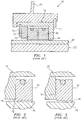
- the shaft sleeve 28 rotates with the shaft 22 during turbine engine operation. Under certain conditions, shaft runout may cause the shaft sleeve 28 and, thus, the seal elements 30 to radially shift relative to the seal housing 26. Referring to FIG. 2 , the radial shifting between each seal element 30 and the seal housing 26 may create an arcuate or annular step 32 in an end 34 of the seal element 30. Referring now to FIG. 3 , this step 32 may fracture during turbine engine operation and increase fluid leakage between the now fractured seal element 30 and the shaft sleeve 28 by providing, for example, a direct leakage passage through axial channels 36.
- a seal assembly with an axis is provided as claimed in claim 1.
- the stator may include a stator surface that axially engages (e.g., contacts) the first element surface and extends radially beyond ends of the first element surface.
- the stator may include a stator surface that extends radially inwards to an inner end having a first radius.
- the first element surface may axially engage the stator surface, and extend radially inwards to an inner end having a second radius that is greater than the first radius.
- the notch may be at least partially formed by a first notch surface that extends axially from an end of the first element surface towards the second element surface.
- the notch may also be at least partially formed by a second notch surface that extends radially from an end of the second element surface towards the first notch surface.
- the first and the second notch surfaces may form the notch with a substantially rectangular cross-sectional geometry.
- the notch may be at least partially formed by a first notch surface and a second notch surface.
- the first notch surface may be substantially perpendicular (or angled) to the second notch surface, and extend axially away from the first element surface towards the second notch surface.
- the second notch surface may extend radially away from the second element surface towards the first notch surface.
- the seal element may shift radially relative to the stator.
- the seal element may also or alternatively shift circumferentially relative to the stator.
- the seal element may be circumferentially fixed relative to the stator.
- the seal element may extend axially between opposing element ends and radially from an inner element side to an outer element side.
- the first element surface may be located at one of the element ends.
- the second element surface may be located at the inner element side.
- the stator may be or include an annular stator that extends circumferentially around and is radially separated from the rotor.
- the stator may be, for example, a turbine engine seal housing within which the seal element is arranged.
- the seal assembly may include a turbine engine shaft on which the rotor (e.g., a sleeve) is mounted.
- the seal element may include a plurality of arcuate seal element segments.
- the seal element may be configured as a unitary body.
- the protrusion may be configured with the stator, and the aperture may be configured with the seal element.
- the protrusion may be configured with the seal element, and the aperture may be configured with the stator.
- FIG. 4 is a sectional illustration of a turbine engine 100 that extends along an axis 102 between an airflow inlet 104 and an airflow exhaust 106.
- the engine 100 includes a fan or low pressure compressor (LPC) section 108, a high pressure compressor (HPC) section 109, a combustor section 110, a high pressure turbine (HPT) section 111, a low pressure turbine (LPT) section 112, an augmentor section 113 and a nozzle section 114.
- LPC low pressure compressor
- HPC high pressure compressor
- HPPT high pressure turbine
- LPT low pressure turbine
- Each of the rotors 118-121 includes a plurality of rotor blades arranged circumferentially around and connected (e.g., mechanically fastened, welded, brazed or otherwise adhered) to one or more respective rotor disks.
- the fan (or LPC) rotor 118 is connected to and driven by the LPT rotor 121 through a low speed shaft 122.
- the HPC rotor 119 is connected to and driven by the HPT rotor 120 through a high speed shaft 124.
- the air within the core gas path 126 may be referred to as "core air”.
- the air within the bypass gas path 128 may be referred to as "bypass air” or "cooling air”.
- the core air is directed through the engine sections 109-114 and exits the engine 100 through the airflow exhaust 106.
- fuel is injected into and mixed with the core air and ignited to provide forward engine thrust.
- the bypass air may be utilized to cool various turbine engine components within one or more of the engine sections 109-114.
- FIG. 5 is a sectional illustration of a seal assembly 130 for sealing a gap between one of the shafts 122 and 124 and a strut 132 connected to the engine case 116.
- the seal assembly 130 includes a stator 134 (e.g., an annular metal seal housing), a rotor 136 (e.g., an annular metal sleeve), seal elements 138 (e.g., annular carbon seal elements), and anti-rotation elements 140.
- stator 134 e.g., an annular metal seal housing
- a rotor 136 e.g., an annular metal sleeve
- seal elements 138 e.g., annular carbon seal elements
- anti-rotation elements 140 e.g., annular carbon seal elements
- the stator 134 includes a pair of endwalls 142, a base 144 and an annular channel 146.
- Each of the endwalls 142 extends radially inwards from an inner surface 148 of the base 144 to an inner side 150.
- each of the endwalls 142 includes a stator surface 152 (e.g., an annular seal surface) that extends radially between an inner end 154 and an outer end 156.
- the inner end 154 is arranged at (e.g., on, adjacent or proximate) the inner side 150.
- the outer end 156 may be arranged at an intersection between the respective endwall 142 and the inner surface 148.
- the channel 146 extends axially within the stator 134 between the stator surfaces 152.
- the channel 146 extends radially into the stator 134 from the inner sides 150 to the inner surface 148.
- each of the seal elements 138 extends circumferentially around the axis 102. Each of the seal elements 138 extends radially between an inner element side 158 and an outer element side 160. Referring now to FIG. 6 , each of the seal elements 138 extends axially between opposing element ends 162 and 164.
- Each of the seal elements 138 includes a plurality of element surfaces 166 and 168 (e.g., annular seal surfaces) and a notch 170 (e.g., an annular relief cut).
- the first element surface 166 is located at the first element end 162.
- the first element surface 166 extends radially between an inner end 172 and an outer end 174.
- the inner end 172 has a radius that is greater than a radius of the inner end 154.
- the second element surface 168 is located at the inner element side 158.
- the second element surface 168 extends axially, in a direction away from the first element surface 166, respectively between a first end 176 and a second end 178.
- the notch 170 extends through the respective seal element 138 circumferentially around the axis 102. Referring to FIG. 9 , the notch 170 extends into a corner of the respective seal element 138 between and adjacent to the ends 172 and 176.
- the notch 170 is defined by one or more notch surfaces 180 and 182.
- the first notch surface 180 extends axially from the inner end 172, in a direction towards the second element surface 168, to the second notch surface 182.
- the second notch surface 182 extends radially from the first end 176, in a direction towards the first element surface 166, to the first notch surface 180.
- the second notch surface 182 may be substantially perpendicular to the first notch surface 180, which provides the notch 170 with a substantially rectangular cross-sectional geometry.
- each of the anti-rotation elements 140 is adapted to prevent a respective one of the seal elements 138 from fully rotating about the axis during turbine engine operation.
- the anti-rotation elements 140 may prevent the seal elements 138 from rotating more than between approximately zero and +/- approximately ten degrees (10°) around the axis.
- the anti-rotation element 140 embodiment of FIG. 6 includes a protrusion 184 (e.g., a pin) that extends axially into an aperture 186 (e.g., a slot or hole).
- the protrusion 184 is configured with the stator 134, and the aperture 186 is configured with the seal element 138.
- the seal elements 138 are arranged within the channel 146 and mated with the stator 134.
- a spring element 188 is arranged axially between the seal elements 138 such that the first element surfaces 166 sealingly engage (e.g., contact) the stator surfaces 152.
- the seal elements 138 are respectively connected to the stator 134 with the anti-rotation elements 140.
- the rotor 136 is mounted onto the shaft 122, 124.
- the rotor 136 is arranged within and mated with the seal elements 138.
- Spring elements 190 may respectively squeeze the seal elements 138 against the rotor 136 such that the second element surfaces 168 sealingly engage a radial outer surface 192 of the rotor 136.
- the inner sides 150 are radially separated from the inner surface 192 by respective radial gaps.
- the rotor 136 rotates with the shaft 122, 124 about the axis during turbine engine operation. Under certain conditions, shaft runout may cause the rotor 136 to radially shift relative to the axis and the stator 134. This shifting of the rotor 136 in turn causes one or more of the seal elements 138 to radially shift relative to the stator 134. Referring to FIG. 6 , the seal assembly 130 may accommodate this radial shifting since each stator surface 152 extends radially beyond the ends 172 and 174. In particular, each of the stator surfaces 152 radially overlaps a portion of the respective notch 170 as well as a gap between the respective seal element 138 and the base 144.
- the first element surfaces 166 therefore substantially maintains full engagement with the stator surfaces 152 during shaft runout. Maintaining full engagement may enable each first element end 162 to wear substantially uniformly, which may prevent fractures in the seal element 138 that may increase fluid leakage through the seal assembly 130.
- One or more seal elements 138 may have various geometries and configurations other than that described above.
- one or more of the seal elements 138 may each include a plurality of arcuate seal element segments 194.
- one or more of the seal elements 138 may each be configured from a unitary body 196 with (or without) a radial expansion slot 198.
- the second notch surface 182 may be obtusely (or acutely) angled relative to the first notch surface 180.
- FIG. 10 the second notch surface 182 may be obtusely (or acutely) angled relative to the first notch surface 180.
- one or more of the seal elements 138 may include one or more circumferential (e.g., annular) channels 200 and 202, one or more axial channels 204 and/or one or more radial channels 206.
- the circumferential channel 200 extends axially into the seal element 138 from the first element surface 166.
- the circumferential channel 202 extends radially into the seal element 138 from the second element surface 168.
- the axial channels 204 and/or the radial channels 206 are arranged circumferentially around the axis.
- the axial channels 204 extend radially into the seal element 138 from the second element surface 168.
- the axial channels 204 may extend axially through the seal element 138 to the circumferential channel 202.
- the radial channels 206 extend axially into the seal element 138 from the first element surface 166.
- the radial channels 206 may extend radially through the seal element 138 to the circumferential channel 200.
- the present invention therefore is not limited to any particular seal element geometries or configurations.
- One or more of the anti-rotation elements 140 may have various configurations other than that described above.
- the protrusion 184 may be configured with the seal element 138, and the aperture 186 maybe configured with the stator 134.
- one or more of the anti-rotation elements 140 may include a fastener that slides within a radially elongated slot. The present invention therefore is not limited to any particular anti-rotation element types or configurations.
- stator 134 and the rotor 136 may have various configurations other than those described above.
- stator may be configured as part of the strut or another turbine engine component.
- rotor may be configured as part of the shaft or another turbine engine component. The present invention therefore is not limited to any particular stator or rotor types or configurations.
- seal assembly 130 may be configured in various types and configurations of turbine engines other than that described above.
- seal assembly 130 may be configured in various types and configurations of rotational equipment other than a turbine engine. The present invention therefore is not limited to any particular rotational equipment types or configurations.
- upstream is used to orientate the components of the seal assembly 130 described above relative to the turbine engine and the axis.
- seal assembly components may be utilized in other orientations than those described above. The present invention therefore is not limited to any particular spatial orientations.
Claims (11)
- Dichtungsanordnung mit einer Achse, umfassend:eine Welle (122, 124);einen Stator (134);einen Rotor (136), der auf der Welle (122, 124) montiert ist; undein erstes ringförmiges Dichtelement (138), das mithilfe eines Drehsicherungselements (140) mit dem Stator (134) verbunden ist, wobei das erste Dichtelement (138) eine erste Elementfläche (166), eine zweite Elementfläche (168) und eine ringförmige Kerbe (170) beinhaltet, wobei die erste Elementfläche (166) axial den Stator (134) in Eingriff nimmt, die zweite Elementfläche (168) des ersten Dichtelements (138) radial den Rotor (136) in Eingriff nimmt und sich die Kerbe (170) des ersten Dichtelements (138) in eine Ecke des ersten Dichtelements (138) zwischen dessen erster und zweiter Elementfläche (166, 168) hineinerstreckt;wobei der Stator (134) radial einen Teil der Kerbe (170) des ersten Dichtelements (138) überlappt,wobei das Drehsicherungselement (140) des ersten Dichtelements (138) einen Vorsprung (184) und eine Aussparung (186) beinhaltet, wobei der Vorsprung (184) axial aus einem von dem Stator (134) und dem ersten Dichtelement (138) hervorragt und sich axial in die Aussparung (186) hineinerstreckt, die mit einem anderen des ersten Dichtelements (138) und des Stators (134) konfiguriert ist, und sich der Vorsprung (184) radial in der Aussparung (186) erstreckt;das erste Dichtelement (138) betreibbar ist, um sich radial relativ zu dem Stator (134) zu verschieben und die erste Elementfläche (166) des ersten Dichtelements (138) betreibbar ist, um während eines Rundlaufs der Welle den vollständigen Eingriff mit dem Stator (134) aufrechtzuerhalten; unddie Dichtungsanordnung ferner ein ringförmiges zweites Dichtelement (138) umfasst, das mithilfe eines Drehsicherungselements (140) mit dem Stator (134) verbunden ist,wobei:das zweite Dichtelement (138) eine erste Elementfläche (166), eine zweite Elementfläche (168) und eine Kerbe (170) beinhaltet; die erste Elementfläche (166) des zweiten Dichtelements (138) axial den Stator (134) in Eingriff nimmt;die zweite Elementfläche (168) des zweiten Dichtelements (138) radial den Rotor (136) in Eingriff nimmt; undsich die Kerbe (170) des zweiten Dichtelements (138) in eine Ecke des zweiten Dichtelements (138) zwischen der jeweiligen ersten und zweiten Elementfläche (166, 168) hineinerstreckt.
- Dichtungsanordnung nach Anspruch 1, wobei der Stator (134) eine Statorfläche (152) beinhaltet, die axial die erste Elementfläche (166) des ersten Dichtelements (138) in Eingriff nimmt und sich radial über Enden der ersten Elementfläche (166) des ersten Dichtelements (138) hinauserstreckt.
- Dichtungsanordnung nach Anspruch 1, wobei
der Stator (134) eine Statorfläche (152) beinhaltet, die sich radial nach innen zu einem inneren Ende (154) erstreckt, das einen ersten Radius aufweist; und
die erste Elementfläche (166) des ersten Dichtelements (138) axial die Statorfläche (152) in Eingriff nimmt und sich radial nach innen zu einem inneren Ende (172) erstreckt, das einen zweiten Radius aufweist, der größer als der erste Radius ist. - Dichtungsanordnung nach Anspruch 1, 2 oder 3, wobei die Kerbe (170) des ersten Dichtelements (138) zumindest teilweise durch eine erste Kerbenfläche (180) gebildet wird, die sich axial von einem Ende der ersten Elementfläche (166) des ersten Dichtelements (138) aus in Richtung der zweiten Elementfläche (168) des ersten Dichtelements (138) erstreckt.
- Dichtungsanordnung nach Anspruch 4, wobei die Kerbe (170) des ersten Dichtelements (138) ferner durch eine zweite Kerbenfläche (182) gebildet wird, die sich radial von einem Ende der zweiten Elementfläche (168) des ersten Dichtelements (138) aus in Richtung der ersten Kerbenfläche (180) erstreckt.
- Dichtungsanordnung nach Anspruch 5, wobei die erste und die zweite Kerbenfläche (180, 182) die Kerbe (170) des ersten Dichtelements (138) mit einer im Wesentlichen rechteckigen Querschnittsgeometrie bilden.
- Dichtungsanordnung nach einem der Ansprüche 1 bis 4, wobei die Kerbe (170) des ersten Dichtelements (138) zumindest teilweise durch eine ersten Kerbenfläche (180) und eine zweite Kerbenfläche (182) gebildet wird;
die erste Kerbenfläche (180) im Wesentlichen senkrecht zu der zweiten Kerbenfläche (182) verläuft und sich axial von der ersten Elementfläche (166) weg in Richtung der zweiten Kerbenfläche (182) erstreckt; und
sich die zweite Kerbenfläche (182) radial von der zweiten Elementfläche (168) weg in Richtung der ersten Kerbenfläche (180) erstreckt. - Dichtungsanordnung nach einem der vorhergehenden Ansprüche, wobei
sich das erste Dichtelement (138) axial zwischen entgegengesetzten Elementenden (162, 164) und radial von einer inneren Elementseite (158) zu einer äußeren Elementseite (160) erstreckt;
sich die erste Elementfläche (166) des ersten Dichtelements (138) an einem der Elementenden (162, 164) befindet; und
sich die zweite Elementfläche (168) des ersten Dichtelements (138) an der inneren Elementseite (158) befindet;
wobei der Stator (134) einen ringförmigen Stator (134) umfasst, der sich in Umfangsrichtung um den Rotor (136) erstreckt und radial von diesem getrennt ist. - Dichtungsanordnung nach einem der vorhergehenden Ansprüche, wobei die Welle (122, 124) eine Turbinentriebwerkswelle ist, auf welcher der Rotor (136) montiert ist.
- Dichtungsanordnung nach einem der vorhergehenden Ansprüche, wobei der Stator (134) ein Turbinentriebwerksdichtungsgehäuse umfasst, in dem das erste Dichtelement (138) angeordnet ist.
- Dichtungsanordnung nach einem der vorhergehenden Ansprüche, wobei das erste Dichtelement (138) eine Vielzahl bogenförmiger Dichtelementsegmente beinhaltet.
Applications Claiming Priority (2)
| Application Number | Priority Date | Filing Date | Title |
|---|---|---|---|
| US201361773539P | 2013-03-06 | 2013-03-06 | |
| PCT/US2014/010341 WO2014158294A2 (en) | 2013-03-06 | 2014-01-06 | Seal assembly including a notched seal element for arranging between a stator and a rotor |
Publications (3)
| Publication Number | Publication Date |
|---|---|
| EP2964901A2 EP2964901A2 (de) | 2016-01-13 |
| EP2964901A4 EP2964901A4 (de) | 2016-07-06 |
| EP2964901B1 true EP2964901B1 (de) | 2021-05-12 |
Family
ID=51625587
Family Applications (1)
| Application Number | Title | Priority Date | Filing Date |
|---|---|---|---|
| EP14773309.1A Active EP2964901B1 (de) | 2013-03-06 | 2014-01-06 | Dichtungsanordnung mit einem gekerbten dichtelement zur anordnung zwischen einem stator und einem rotor |
Country Status (3)
| Country | Link |
|---|---|
| US (1) | US9982553B2 (de) |
| EP (1) | EP2964901B1 (de) |
| WO (1) | WO2014158294A2 (de) |
Families Citing this family (12)
| Publication number | Priority date | Publication date | Assignee | Title |
|---|---|---|---|---|
| WO2015065731A1 (en) * | 2013-10-28 | 2015-05-07 | United Technologies Corporation | Radial seal with offset relief cut |
| DE102016218239A1 (de) | 2016-09-22 | 2018-03-22 | MTU Aero Engines AG | Dichtungsanordnung für ein Turbinenzwischengehäuse einer Gasturbine |
| US10145255B2 (en) * | 2017-01-13 | 2018-12-04 | United Technologies Corporation | Constant speed 2 piece ring seal arrangement |
| US10208610B2 (en) * | 2017-04-06 | 2019-02-19 | United Technologies Corporation | Ring seal arrangement |
| US10392953B2 (en) | 2017-06-15 | 2019-08-27 | United Technologies Corporation | Ring seal arrangement |
| US10619742B2 (en) * | 2017-07-14 | 2020-04-14 | United Technologies Corporation | Ring seal arrangement with installation foolproofing |
| US11199262B2 (en) * | 2017-08-07 | 2021-12-14 | Eagle Industry Co., Ltd. | Segment seal |
| FR3079013B1 (fr) * | 2018-03-14 | 2021-02-26 | Safran Aircraft Engines | Dispositif annulaire d'etancheite |
| US11287043B2 (en) * | 2019-08-02 | 2022-03-29 | Kaydon Ring & Seal, Inc. | High clearance seal assembly |
| US11365640B2 (en) | 2019-09-19 | 2022-06-21 | Raytheon Technologies Corporation | Seal assembly with anti-rotation lock |
| US11371373B2 (en) | 2019-10-29 | 2022-06-28 | Raytheon Technologies Corporation | Seal assembly for use in gas turbine engines |
| US11892083B2 (en) * | 2022-04-06 | 2024-02-06 | Rtx Corporation | Piston seal ring |
Family Cites Families (12)
| Publication number | Priority date | Publication date | Assignee | Title |
|---|---|---|---|---|
| US2908516A (en) * | 1954-08-02 | 1959-10-13 | Koppers Co Inc | Circumferential shaft seal |
| US3575424A (en) | 1969-11-28 | 1971-04-20 | Koppers Co Inc | Pressure balanced circumferential seal assembly |
| US4094513A (en) * | 1976-09-13 | 1978-06-13 | Chemineer, Inc. | Fully cartridge agitator seal for use with glass lined mixer tanks |
| DE3436798A1 (de) * | 1984-10-06 | 1986-04-17 | Goetze Ag, 5093 Burscheid | Gleitringdichtung |
| US5014999A (en) | 1989-03-06 | 1991-05-14 | Car-Graph, Inc. | Pressure enhanced self aligning seal |
| US5217232A (en) * | 1992-04-28 | 1993-06-08 | Car-Graph, Inc. | Thermally regulated segmented seal |
| US5558341A (en) * | 1995-01-11 | 1996-09-24 | Stein Seal Company | Seal for sealing an incompressible fluid between a relatively stationary seal and a movable member |
| CA2167424C (en) * | 1995-02-02 | 2002-02-19 | David C. Orlowski | Emission seal |
| FR2782122B1 (fr) * | 1998-08-05 | 2000-09-15 | Snecma | Agencement d'etancheite a reglage automatique de jeu |
| US6692006B2 (en) | 2001-10-15 | 2004-02-17 | Stein Seal Company | High-pressure film-riding seals for rotating shafts |
| US8167314B2 (en) | 2009-03-31 | 2012-05-01 | United Technologies Corporation | Distortion resistant face seal counterface system |
| US8777229B2 (en) * | 2010-03-26 | 2014-07-15 | United Technologies Corporation | Liftoff carbon seal |
-
2014
- 2014-01-06 US US14/771,964 patent/US9982553B2/en active Active
- 2014-01-06 WO PCT/US2014/010341 patent/WO2014158294A2/en active Application Filing
- 2014-01-06 EP EP14773309.1A patent/EP2964901B1/de active Active
Non-Patent Citations (1)
| Title |
|---|
| None * |
Also Published As
| Publication number | Publication date |
|---|---|
| EP2964901A4 (de) | 2016-07-06 |
| WO2014158294A2 (en) | 2014-10-02 |
| EP2964901A2 (de) | 2016-01-13 |
| US9982553B2 (en) | 2018-05-29 |
| US20160010483A1 (en) | 2016-01-14 |
| WO2014158294A3 (en) | 2014-12-18 |
Similar Documents
| Publication | Publication Date | Title |
|---|---|---|
| EP2964901B1 (de) | Dichtungsanordnung mit einem gekerbten dichtelement zur anordnung zwischen einem stator und einem rotor | |
| US10208615B2 (en) | Seal shoe for a hydrostatic non-contact seal device | |
| EP3196517B1 (de) | Sekundärdichtungsvorrichtung(en) mit ausrichtungslasche(n) | |
| EP2949874B1 (de) | Doppelwandige dichtungsanordnung | |
| US10088049B2 (en) | Thermally protected seal assembly | |
| CA2523183A1 (en) | Circumferential feather seal | |
| US10550708B2 (en) | Floating, non-contact seal with at least three beams | |
| US9316119B2 (en) | Turbomachine secondary seal assembly | |
| US10337621B2 (en) | Hydrostatic non-contact seal with weight reduction pocket | |
| US9759081B2 (en) | Method and system to facilitate sealing in gas turbines | |
| US10655481B2 (en) | Cover plate for rotor assembly of a gas turbine engine | |
| EP2904241B1 (de) | Fehlhandlungssichere brennkammerdichtung für einen gasturbinenmotor | |
| US10557362B2 (en) | Method and system for a pressure activated cap seal | |
| US20200025008A1 (en) | Seal assembly for sealing an axial gap between components | |
| US10982559B2 (en) | Spline seal with cooling features for turbine engines | |
| US10598035B2 (en) | Intershaft sealing systems for gas turbine engines and methods for assembling the same | |
| US11371441B2 (en) | Translating fluid delivery device | |
| EP3830396B1 (de) | Berührungsfreie dichtung mit verdrehsicherung | |
| WO2020050837A1 (en) | Non-contact seal with mechanical fit | |
| US11365640B2 (en) | Seal assembly with anti-rotation lock |
Legal Events
| Date | Code | Title | Description |
|---|---|---|---|
| PUAI | Public reference made under article 153(3) epc to a published international application that has entered the european phase |
Free format text: ORIGINAL CODE: 0009012 |
|
| 17P | Request for examination filed |
Effective date: 20151005 |
|
| AK | Designated contracting states |
Kind code of ref document: A2 Designated state(s): AL AT BE BG CH CY CZ DE DK EE ES FI FR GB GR HR HU IE IS IT LI LT LU LV MC MK MT NL NO PL PT RO RS SE SI SK SM TR |
|
| AX | Request for extension of the european patent |
Extension state: BA ME |
|
| DAX | Request for extension of the european patent (deleted) | ||
| A4 | Supplementary search report drawn up and despatched |
Effective date: 20160607 |
|
| RIC1 | Information provided on ipc code assigned before grant |
Ipc: F01D 11/00 20060101AFI20160601BHEP Ipc: F01D 11/08 20060101ALI20160601BHEP Ipc: F16J 15/44 20060101ALN20160601BHEP Ipc: F02C 7/28 20060101ALI20160601BHEP Ipc: F01D 9/00 20060101ALI20160601BHEP Ipc: F04D 29/10 20060101ALI20160601BHEP |
|
| RAP1 | Party data changed (applicant data changed or rights of an application transferred) |
Owner name: UNITED TECHNOLOGIES CORPORATION |
|
| STAA | Information on the status of an ep patent application or granted ep patent |
Free format text: STATUS: EXAMINATION IS IN PROGRESS |
|
| 17Q | First examination report despatched |
Effective date: 20200107 |
|
| RIC1 | Information provided on ipc code assigned before grant |
Ipc: F01D 9/00 20060101ALI20200527BHEP Ipc: F16J 15/44 20060101ALN20200527BHEP Ipc: F04D 29/10 20060101ALI20200527BHEP Ipc: F01D 11/08 20060101ALI20200527BHEP Ipc: F01D 11/00 20060101AFI20200527BHEP Ipc: F02C 7/28 20060101ALI20200527BHEP |
|
| GRAP | Despatch of communication of intention to grant a patent |
Free format text: ORIGINAL CODE: EPIDOSNIGR1 |
|
| STAA | Information on the status of an ep patent application or granted ep patent |
Free format text: STATUS: GRANT OF PATENT IS INTENDED |
|
| INTG | Intention to grant announced |
Effective date: 20200714 |
|
| GRAJ | Information related to disapproval of communication of intention to grant by the applicant or resumption of examination proceedings by the epo deleted |
Free format text: ORIGINAL CODE: EPIDOSDIGR1 |
|
| STAA | Information on the status of an ep patent application or granted ep patent |
Free format text: STATUS: EXAMINATION IS IN PROGRESS |
|
| GRAP | Despatch of communication of intention to grant a patent |
Free format text: ORIGINAL CODE: EPIDOSNIGR1 |
|
| INTC | Intention to grant announced (deleted) | ||
| STAA | Information on the status of an ep patent application or granted ep patent |
Free format text: STATUS: GRANT OF PATENT IS INTENDED |
|
| RIC1 | Information provided on ipc code assigned before grant |
Ipc: F16J 15/44 20060101ALN20201027BHEP Ipc: F04D 29/10 20060101ALI20201027BHEP Ipc: F01D 11/00 20060101AFI20201027BHEP Ipc: F01D 9/00 20060101ALI20201027BHEP Ipc: F01D 11/08 20060101ALI20201027BHEP Ipc: F02C 7/28 20060101ALI20201027BHEP |
|
| INTG | Intention to grant announced |
Effective date: 20201126 |
|
| RAP1 | Party data changed (applicant data changed or rights of an application transferred) |
Owner name: RAYTHEON TECHNOLOGIES CORPORATION |
|
| GRAS | Grant fee paid |
Free format text: ORIGINAL CODE: EPIDOSNIGR3 |
|
| GRAA | (expected) grant |
Free format text: ORIGINAL CODE: 0009210 |
|
| STAA | Information on the status of an ep patent application or granted ep patent |
Free format text: STATUS: THE PATENT HAS BEEN GRANTED |
|
| AK | Designated contracting states |
Kind code of ref document: B1 Designated state(s): AL AT BE BG CH CY CZ DE DK EE ES FI FR GB GR HR HU IE IS IT LI LT LU LV MC MK MT NL NO PL PT RO RS SE SI SK SM TR |
|
| REG | Reference to a national code |
Ref country code: GB Ref legal event code: FG4D |
|
| REG | Reference to a national code |
Ref country code: CH Ref legal event code: EP |
|
| REG | Reference to a national code |
Ref country code: DE Ref legal event code: R096 Ref document number: 602014077412 Country of ref document: DE |
|
| REG | Reference to a national code |
Ref country code: IE Ref legal event code: FG4D |
|
| REG | Reference to a national code |
Ref country code: AT Ref legal event code: REF Ref document number: 1392292 Country of ref document: AT Kind code of ref document: T Effective date: 20210615 |
|
| REG | Reference to a national code |
Ref country code: LT Ref legal event code: MG9D |
|
| REG | Reference to a national code |
Ref country code: AT Ref legal event code: MK05 Ref document number: 1392292 Country of ref document: AT Kind code of ref document: T Effective date: 20210512 |
|
| REG | Reference to a national code |
Ref country code: NL Ref legal event code: MP Effective date: 20210512 |
|
| PG25 | Lapsed in a contracting state [announced via postgrant information from national office to epo] |
Ref country code: HR Free format text: LAPSE BECAUSE OF FAILURE TO SUBMIT A TRANSLATION OF THE DESCRIPTION OR TO PAY THE FEE WITHIN THE PRESCRIBED TIME-LIMIT Effective date: 20210512 Ref country code: BG Free format text: LAPSE BECAUSE OF FAILURE TO SUBMIT A TRANSLATION OF THE DESCRIPTION OR TO PAY THE FEE WITHIN THE PRESCRIBED TIME-LIMIT Effective date: 20210812 Ref country code: AT Free format text: LAPSE BECAUSE OF FAILURE TO SUBMIT A TRANSLATION OF THE DESCRIPTION OR TO PAY THE FEE WITHIN THE PRESCRIBED TIME-LIMIT Effective date: 20210512 Ref country code: FI Free format text: LAPSE BECAUSE OF FAILURE TO SUBMIT A TRANSLATION OF THE DESCRIPTION OR TO PAY THE FEE WITHIN THE PRESCRIBED TIME-LIMIT Effective date: 20210512 Ref country code: LT Free format text: LAPSE BECAUSE OF FAILURE TO SUBMIT A TRANSLATION OF THE DESCRIPTION OR TO PAY THE FEE WITHIN THE PRESCRIBED TIME-LIMIT Effective date: 20210512 |
|
| PG25 | Lapsed in a contracting state [announced via postgrant information from national office to epo] |
Ref country code: IS Free format text: LAPSE BECAUSE OF FAILURE TO SUBMIT A TRANSLATION OF THE DESCRIPTION OR TO PAY THE FEE WITHIN THE PRESCRIBED TIME-LIMIT Effective date: 20210912 Ref country code: GR Free format text: LAPSE BECAUSE OF FAILURE TO SUBMIT A TRANSLATION OF THE DESCRIPTION OR TO PAY THE FEE WITHIN THE PRESCRIBED TIME-LIMIT Effective date: 20210813 Ref country code: LV Free format text: LAPSE BECAUSE OF FAILURE TO SUBMIT A TRANSLATION OF THE DESCRIPTION OR TO PAY THE FEE WITHIN THE PRESCRIBED TIME-LIMIT Effective date: 20210512 Ref country code: PL Free format text: LAPSE BECAUSE OF FAILURE TO SUBMIT A TRANSLATION OF THE DESCRIPTION OR TO PAY THE FEE WITHIN THE PRESCRIBED TIME-LIMIT Effective date: 20210512 Ref country code: NO Free format text: LAPSE BECAUSE OF FAILURE TO SUBMIT A TRANSLATION OF THE DESCRIPTION OR TO PAY THE FEE WITHIN THE PRESCRIBED TIME-LIMIT Effective date: 20210812 Ref country code: PT Free format text: LAPSE BECAUSE OF FAILURE TO SUBMIT A TRANSLATION OF THE DESCRIPTION OR TO PAY THE FEE WITHIN THE PRESCRIBED TIME-LIMIT Effective date: 20210913 Ref country code: ES Free format text: LAPSE BECAUSE OF FAILURE TO SUBMIT A TRANSLATION OF THE DESCRIPTION OR TO PAY THE FEE WITHIN THE PRESCRIBED TIME-LIMIT Effective date: 20210512 Ref country code: RS Free format text: LAPSE BECAUSE OF FAILURE TO SUBMIT A TRANSLATION OF THE DESCRIPTION OR TO PAY THE FEE WITHIN THE PRESCRIBED TIME-LIMIT Effective date: 20210512 Ref country code: SE Free format text: LAPSE BECAUSE OF FAILURE TO SUBMIT A TRANSLATION OF THE DESCRIPTION OR TO PAY THE FEE WITHIN THE PRESCRIBED TIME-LIMIT Effective date: 20210512 |
|
| PG25 | Lapsed in a contracting state [announced via postgrant information from national office to epo] |
Ref country code: NL Free format text: LAPSE BECAUSE OF FAILURE TO SUBMIT A TRANSLATION OF THE DESCRIPTION OR TO PAY THE FEE WITHIN THE PRESCRIBED TIME-LIMIT Effective date: 20210512 |
|
| PG25 | Lapsed in a contracting state [announced via postgrant information from national office to epo] |
Ref country code: RO Free format text: LAPSE BECAUSE OF FAILURE TO SUBMIT A TRANSLATION OF THE DESCRIPTION OR TO PAY THE FEE WITHIN THE PRESCRIBED TIME-LIMIT Effective date: 20210512 Ref country code: CZ Free format text: LAPSE BECAUSE OF FAILURE TO SUBMIT A TRANSLATION OF THE DESCRIPTION OR TO PAY THE FEE WITHIN THE PRESCRIBED TIME-LIMIT Effective date: 20210512 Ref country code: DK Free format text: LAPSE BECAUSE OF FAILURE TO SUBMIT A TRANSLATION OF THE DESCRIPTION OR TO PAY THE FEE WITHIN THE PRESCRIBED TIME-LIMIT Effective date: 20210512 Ref country code: EE Free format text: LAPSE BECAUSE OF FAILURE TO SUBMIT A TRANSLATION OF THE DESCRIPTION OR TO PAY THE FEE WITHIN THE PRESCRIBED TIME-LIMIT Effective date: 20210512 Ref country code: SK Free format text: LAPSE BECAUSE OF FAILURE TO SUBMIT A TRANSLATION OF THE DESCRIPTION OR TO PAY THE FEE WITHIN THE PRESCRIBED TIME-LIMIT Effective date: 20210512 Ref country code: SM Free format text: LAPSE BECAUSE OF FAILURE TO SUBMIT A TRANSLATION OF THE DESCRIPTION OR TO PAY THE FEE WITHIN THE PRESCRIBED TIME-LIMIT Effective date: 20210512 |
|
| REG | Reference to a national code |
Ref country code: DE Ref legal event code: R097 Ref document number: 602014077412 Country of ref document: DE |
|
| PLBE | No opposition filed within time limit |
Free format text: ORIGINAL CODE: 0009261 |
|
| STAA | Information on the status of an ep patent application or granted ep patent |
Free format text: STATUS: NO OPPOSITION FILED WITHIN TIME LIMIT |
|
| 26N | No opposition filed |
Effective date: 20220215 |
|
| PG25 | Lapsed in a contracting state [announced via postgrant information from national office to epo] |
Ref country code: IS Free format text: LAPSE BECAUSE OF FAILURE TO SUBMIT A TRANSLATION OF THE DESCRIPTION OR TO PAY THE FEE WITHIN THE PRESCRIBED TIME-LIMIT Effective date: 20210912 Ref country code: AL Free format text: LAPSE BECAUSE OF FAILURE TO SUBMIT A TRANSLATION OF THE DESCRIPTION OR TO PAY THE FEE WITHIN THE PRESCRIBED TIME-LIMIT Effective date: 20210512 |
|
| PG25 | Lapsed in a contracting state [announced via postgrant information from national office to epo] |
Ref country code: IT Free format text: LAPSE BECAUSE OF FAILURE TO SUBMIT A TRANSLATION OF THE DESCRIPTION OR TO PAY THE FEE WITHIN THE PRESCRIBED TIME-LIMIT Effective date: 20210512 |
|
| PG25 | Lapsed in a contracting state [announced via postgrant information from national office to epo] |
Ref country code: MC Free format text: LAPSE BECAUSE OF FAILURE TO SUBMIT A TRANSLATION OF THE DESCRIPTION OR TO PAY THE FEE WITHIN THE PRESCRIBED TIME-LIMIT Effective date: 20210512 |
|
| REG | Reference to a national code |
Ref country code: CH Ref legal event code: PL |
|
| REG | Reference to a national code |
Ref country code: BE Ref legal event code: MM Effective date: 20220131 |
|
| PG25 | Lapsed in a contracting state [announced via postgrant information from national office to epo] |
Ref country code: LU Free format text: LAPSE BECAUSE OF NON-PAYMENT OF DUE FEES Effective date: 20220106 |
|
| PG25 | Lapsed in a contracting state [announced via postgrant information from national office to epo] |
Ref country code: BE Free format text: LAPSE BECAUSE OF NON-PAYMENT OF DUE FEES Effective date: 20220131 |
|
| PG25 | Lapsed in a contracting state [announced via postgrant information from national office to epo] |
Ref country code: LI Free format text: LAPSE BECAUSE OF NON-PAYMENT OF DUE FEES Effective date: 20220131 Ref country code: CH Free format text: LAPSE BECAUSE OF NON-PAYMENT OF DUE FEES Effective date: 20220131 |
|
| PG25 | Lapsed in a contracting state [announced via postgrant information from national office to epo] |
Ref country code: IE Free format text: LAPSE BECAUSE OF NON-PAYMENT OF DUE FEES Effective date: 20220106 |
|
| PGFP | Annual fee paid to national office [announced via postgrant information from national office to epo] |
Ref country code: DE Payment date: 20221220 Year of fee payment: 10 |
|
| P01 | Opt-out of the competence of the unified patent court (upc) registered |
Effective date: 20230520 |
|
| PGFP | Annual fee paid to national office [announced via postgrant information from national office to epo] |
Ref country code: GB Payment date: 20231219 Year of fee payment: 11 |
|
| PGFP | Annual fee paid to national office [announced via postgrant information from national office to epo] |
Ref country code: FR Payment date: 20231219 Year of fee payment: 11 |
|
| PG25 | Lapsed in a contracting state [announced via postgrant information from national office to epo] |
Ref country code: HU Free format text: LAPSE BECAUSE OF FAILURE TO SUBMIT A TRANSLATION OF THE DESCRIPTION OR TO PAY THE FEE WITHIN THE PRESCRIBED TIME-LIMIT; INVALID AB INITIO Effective date: 20140106 |