EP2964301B1 - Patient interfaces with condensation reducing or compensating arrangements - Google Patents
Patient interfaces with condensation reducing or compensating arrangements Download PDFInfo
- Publication number
- EP2964301B1 EP2964301B1 EP14759826.2A EP14759826A EP2964301B1 EP 2964301 B1 EP2964301 B1 EP 2964301B1 EP 14759826 A EP14759826 A EP 14759826A EP 2964301 B1 EP2964301 B1 EP 2964301B1
- Authority
- EP
- European Patent Office
- Prior art keywords
- mask
- layer
- patient interface
- mask assembly
- water vapor
- Prior art date
- Legal status (The legal status is an assumption and is not a legal conclusion. Google has not performed a legal analysis and makes no representation as to the accuracy of the status listed.)
- Active
Links
- 0 CC1[C@](C)C2[C@]3C=CC(C4)=*4C3C12 Chemical compound CC1[C@](C)C2[C@]3C=CC(C4)=*4C3C12 0.000 description 1
Images


Classifications
-
- A—HUMAN NECESSITIES
- A61—MEDICAL OR VETERINARY SCIENCE; HYGIENE
- A61M—DEVICES FOR INTRODUCING MEDIA INTO, OR ONTO, THE BODY; DEVICES FOR TRANSDUCING BODY MEDIA OR FOR TAKING MEDIA FROM THE BODY; DEVICES FOR PRODUCING OR ENDING SLEEP OR STUPOR
- A61M16/00—Devices for influencing the respiratory system of patients by gas treatment, e.g. mouth-to-mouth respiration; Tracheal tubes
- A61M16/08—Bellows; Connecting tubes ; Water traps; Patient circuits
- A61M16/0808—Condensation traps
-
- A—HUMAN NECESSITIES
- A61—MEDICAL OR VETERINARY SCIENCE; HYGIENE
- A61M—DEVICES FOR INTRODUCING MEDIA INTO, OR ONTO, THE BODY; DEVICES FOR TRANSDUCING BODY MEDIA OR FOR TAKING MEDIA FROM THE BODY; DEVICES FOR PRODUCING OR ENDING SLEEP OR STUPOR
- A61M16/00—Devices for influencing the respiratory system of patients by gas treatment, e.g. mouth-to-mouth respiration; Tracheal tubes
- A61M16/0057—Pumps therefor
-
- A—HUMAN NECESSITIES
- A61—MEDICAL OR VETERINARY SCIENCE; HYGIENE
- A61M—DEVICES FOR INTRODUCING MEDIA INTO, OR ONTO, THE BODY; DEVICES FOR TRANSDUCING BODY MEDIA OR FOR TAKING MEDIA FROM THE BODY; DEVICES FOR PRODUCING OR ENDING SLEEP OR STUPOR
- A61M16/00—Devices for influencing the respiratory system of patients by gas treatment, e.g. mouth-to-mouth respiration; Tracheal tubes
- A61M16/06—Respiratory or anaesthetic masks
- A61M16/0605—Means for improving the adaptation of the mask to the patient
- A61M16/0611—Means for improving the adaptation of the mask to the patient with a gusset portion
-
- A—HUMAN NECESSITIES
- A61—MEDICAL OR VETERINARY SCIENCE; HYGIENE
- A61M—DEVICES FOR INTRODUCING MEDIA INTO, OR ONTO, THE BODY; DEVICES FOR TRANSDUCING BODY MEDIA OR FOR TAKING MEDIA FROM THE BODY; DEVICES FOR PRODUCING OR ENDING SLEEP OR STUPOR
- A61M16/00—Devices for influencing the respiratory system of patients by gas treatment, e.g. mouth-to-mouth respiration; Tracheal tubes
- A61M16/06—Respiratory or anaesthetic masks
- A61M16/0605—Means for improving the adaptation of the mask to the patient
- A61M16/0616—Means for improving the adaptation of the mask to the patient with face sealing means comprising a flap or membrane projecting inwards, such that sealing increases with increasing inhalation gas pressure
- A61M16/0622—Means for improving the adaptation of the mask to the patient with face sealing means comprising a flap or membrane projecting inwards, such that sealing increases with increasing inhalation gas pressure having an underlying cushion
-
- A—HUMAN NECESSITIES
- A61—MEDICAL OR VETERINARY SCIENCE; HYGIENE
- A61M—DEVICES FOR INTRODUCING MEDIA INTO, OR ONTO, THE BODY; DEVICES FOR TRANSDUCING BODY MEDIA OR FOR TAKING MEDIA FROM THE BODY; DEVICES FOR PRODUCING OR ENDING SLEEP OR STUPOR
- A61M16/00—Devices for influencing the respiratory system of patients by gas treatment, e.g. mouth-to-mouth respiration; Tracheal tubes
- A61M16/08—Bellows; Connecting tubes ; Water traps; Patient circuits
- A61M16/0816—Joints or connectors
-
- A—HUMAN NECESSITIES
- A61—MEDICAL OR VETERINARY SCIENCE; HYGIENE
- A61M—DEVICES FOR INTRODUCING MEDIA INTO, OR ONTO, THE BODY; DEVICES FOR TRANSDUCING BODY MEDIA OR FOR TAKING MEDIA FROM THE BODY; DEVICES FOR PRODUCING OR ENDING SLEEP OR STUPOR
- A61M16/00—Devices for influencing the respiratory system of patients by gas treatment, e.g. mouth-to-mouth respiration; Tracheal tubes
- A61M16/08—Bellows; Connecting tubes ; Water traps; Patient circuits
- A61M16/0875—Connecting tubes
-
- A—HUMAN NECESSITIES
- A61—MEDICAL OR VETERINARY SCIENCE; HYGIENE
- A61M—DEVICES FOR INTRODUCING MEDIA INTO, OR ONTO, THE BODY; DEVICES FOR TRANSDUCING BODY MEDIA OR FOR TAKING MEDIA FROM THE BODY; DEVICES FOR PRODUCING OR ENDING SLEEP OR STUPOR
- A61M16/00—Devices for influencing the respiratory system of patients by gas treatment, e.g. mouth-to-mouth respiration; Tracheal tubes
- A61M16/10—Preparation of respiratory gases or vapours
- A61M16/1045—Devices for humidifying or heating the inspired gas by using recovered moisture or heat from the expired gas
-
- A—HUMAN NECESSITIES
- A61—MEDICAL OR VETERINARY SCIENCE; HYGIENE
- A61M—DEVICES FOR INTRODUCING MEDIA INTO, OR ONTO, THE BODY; DEVICES FOR TRANSDUCING BODY MEDIA OR FOR TAKING MEDIA FROM THE BODY; DEVICES FOR PRODUCING OR ENDING SLEEP OR STUPOR
- A61M16/00—Devices for influencing the respiratory system of patients by gas treatment, e.g. mouth-to-mouth respiration; Tracheal tubes
- A61M16/10—Preparation of respiratory gases or vapours
- A61M16/1075—Preparation of respiratory gases or vapours by influencing the temperature
- A61M16/1095—Preparation of respiratory gases or vapours by influencing the temperature in the connecting tubes
-
- A—HUMAN NECESSITIES
- A61—MEDICAL OR VETERINARY SCIENCE; HYGIENE
- A61M—DEVICES FOR INTRODUCING MEDIA INTO, OR ONTO, THE BODY; DEVICES FOR TRANSDUCING BODY MEDIA OR FOR TAKING MEDIA FROM THE BODY; DEVICES FOR PRODUCING OR ENDING SLEEP OR STUPOR
- A61M2205/00—General characteristics of the apparatus
- A61M2205/14—Detection of the presence or absence of a tube, a connector or a container in an apparatus
-
- A—HUMAN NECESSITIES
- A61—MEDICAL OR VETERINARY SCIENCE; HYGIENE
- A61M—DEVICES FOR INTRODUCING MEDIA INTO, OR ONTO, THE BODY; DEVICES FOR TRANSDUCING BODY MEDIA OR FOR TAKING MEDIA FROM THE BODY; DEVICES FOR PRODUCING OR ENDING SLEEP OR STUPOR
- A61M2205/00—General characteristics of the apparatus
- A61M2205/36—General characteristics of the apparatus related to heating or cooling
- A61M2205/3653—General characteristics of the apparatus related to heating or cooling by Joule effect, i.e. electric resistance
Definitions
- the present disclosure relates generally to respiratory therapy systems.
- the present disclosure relates to patient interfaces, such as mask assemblies and breathing circuits, with condensation reducing or compensating configurations.
- CPAP therapy commonly used to treat obstructive sleep apnea, pumps air to a patient to maintain a minimum pressure in the airways. Often the air is heated and humidified before being sent to the patient. This causes less dryness and irritation to the patient and can increase compliance in the therapy. An issue with humidified air is that it can condense into water, becoming rainout. This is due to the heated air cooling down and the air reaches a dew point, causing condensation.
- Rainout can cause several problems, including the following: the water can restrict airflow to the patient or out of the mask; water can form into droplets and drip on a patients face which can wake them; a whistling noise can result when water forms on the vent holes; water can disrupt the mask seal against the patient's face; the patient may wake with a wet face which can feel unpleasant.
- GB 2 470 804 which discloses a mask with a membrane that forms an intermediary chamber between the users face and the mask wall, the intermediate chamber inhibits condensate dripping on to the users face. It also includes a single hole for draining the intermediate chamber.
- US 2011/232646 A1 is also relevant prior art and discloses a mask with a filter for the gases provided to patient. It discloses ventilation holes that allow gases to flow in or out of an intermediated chamber and a filter between the users face and the outer surface of the mask.
- Mask assemblies, breathing circuits and related components described herein include configurations for reducing condensation within the mask and/or inhibiting or preventing condensation from coming into contact with a user of the mask.
- the mask assemblies can incorporate heating elements (such as heating coils), insulating spaces or barrier layers.
- a patient interface comprising a body adapted to form a seal with a user's face, a coupling for fluid connection to a gas delivery system, a water vapor breathable membrane layer, and an outer layer with holes that allows gases to flow into an intermediary chamber between the water vapor breathable membrane layer and the outer layer.
- the patient interface is configured such that the water vapor breathable membrane layer is positioned between the user's face and the outer layer and inhibits or prevents water condensate in the intermediary chamber from passing through the water vapor breathable membrane layer and dripping onto the user's face in use
- the patient interface further comprises a vent that allows a flow of gases from an interior of the body to an exterior of the body.
- the vent can be configured so that the flow of gases entrains air from the environment into the intermediary chamber.
- the vent comprises a hydrophobic material and an area adjacent the vent can comprise a hydrophilic material.
- the holes on the outer layer can be disposed at or near the perimeter of the outer layer.
- the body comprises a silicone seal member.
- a patient interface comprising a body adapted to form a seal with a user's face, the body comprising an inner layer, an outer layer, and an insulation space between the inner and outer layers.
- the patient interface can comprise a coupling for fluid connection to a gas delivery system.
- the patient interface further comprises a heating element disposed in the insulation space.
- the patient interface can further comprise a vent that allows a flow of gases from an interior of the body to an exterior of the body.
- the vent can be recessed and disposed adjacent the inner layer.
- the insulation space can be in fluid communication with the vent.
- the body can be configured so that the flow of gases flows through the insulation space before exiting the interface.
- the outer layer is releasably attached to the inner layer.
- the patient interface can further comprise at least one heat pad coupled to the outer layer.
- the patient interface further comprises a phase change material in the insulation space.
- the inner layer can be configured to diffuse gases from the gas delivery system and can be heated by the gases.
- a patient interface comprising a foamed breathable membrane body that allows water vapor to pass through the body, a frame structure attached to the foamed breathable membrane body, and a coupling for fluid connection to a gas delivery system.
- the patient interface further comprises a water vapor breathable layer.
- the patient interface can further comprise a vent that allows a flow of gases from an interior of the interface to an exterior of the interface.
- the patient interface can further comprise a seal adapted to form at least a substantial seal with a user's face.
- the foamed breathable membrane body may be ribbed.
- a patient interface comprising a body adapted to form a seal with a user's face, the body comprising an inner layer made of a thermally conductive material and an outer layer made of an insulating material.
- the patient interface can further comprise a coupling for fluid connection to a gas delivery system.
- the patient interface further comprises a vent that allows a flow of gases from an interior of the body to an exterior of the body.
- the patient interface further comprises a heating element in thermal communication with the inner layer.
- the thermally conductive material can be a polymer.
- the thermally conductive material can be a metal.
- the patient interface further comprises a thermoelectric cooling device in thermal communication with the inner layer.
- the patient interface can further comprise a sensor to provide feedback of the temperature of the inner layer.
- Figures 1 and 2 illustrate interfaces, specifically mask assemblies 100, comprising heating elements 110, such as for example heating coils.
- the heating elements 110 can be moulded into the mask as in the illustrated configuration, or otherwise secured to the mask such as through adhesives, clips, welding or the like. In some configurations, the heating elements are attached to the inner surface of the mask.
- the heating elements 110 can wind throughout a substantial portion or all of the mask's inner surface. Preferably the heating elements are sufficiently distributed on the surface area of the mask to evenly or substantially evenly heat the interior space of the mask.
- the heating elements 110 can be powered by the electrical current from the CPAP or other flow generator/humidifier system. Power can be supplied directly to the mask assembly 100 such as via a separate power line. In some configurations, the power can be conveyed through another component of the system, such as the breathing tube 120 or circuit, for example.
- FIGs 48 and 49 illustrate mask assemblies comprising heating elements with alternative or auxiliary power configurations for powering the heating elements.
- heating elements 210 e.g., copper wire or other conductive material
- the generator 212 can comprise any suitable configuration, such as a small fan and motor placed in the mask so that airflow from the CPAP (or other flow generator) will cause the fan blades to rotate (or otherwise power the generator). The rotation will produce an electrical current that passes through the heating element 210.
- Figure 49 illustrates a mask assembly 300 with in-moulded heating elements 310 (e.g., copper coils or other conductive material) that form a circuit with a circuit board 312 attached to a suitable location (e.g., the exterior) of the mask.
- the circuit board 312 can contain a battery 314 to power the heating element 310 with current and, optionally, a microcontroller and/or sensors (such as a temperature sensor) to allow smart control of the heating element 310.
- Figure 3 illustrates a mask assembly 400 having one or more loops of heating element 410.
- the one or more loops of heating element 410 can be clamped in place by a retaining mechanism 412, such as plastic hooks or tabs, similar to the ones used to connect the mask strap to the mask in the GLIDERTM strap configurations used in the FLEXIFITTM series nasal masks sold by Fisher & Paykel Healthcare.
- a suitable configuration is disclosed in international patent publication number WO2011/077254 A2 , especially in Figure 27 .
- the heating element can be of any suitable construction, such as the same as or similar to that used in the Evaqua 2TM breathing circuit sold by Fisher & Paykel Healthcare.
- Figure 4 illustrates a section of an example of a suitable heating element 410, which comprises a core 414 with conductive coil 416 (e.g., copper) wound around it, and an outer cover 418 around the core.
- the core can be made of string and the outer cover can be a plastic tube.
- interfaces are full face masks, the scope of the present disclosure should not be limited by the particular embodiments described.
- the interfaces can comprise any of a plurality of different types of suitable mask configurations.
- certain features, aspects and advantages of the present invention can be utilized with nasal masks, full face masks, oronasal masks or any other positive pressure mask.
- a breathing tube 520 can have at least one length of heating element 510 (e.g., coiled heating wire) disposed inside the tube, which can extend at least partially outside the tube.
- the portion of the heating element that extends outside the tube can be clipped into a mask and used as a heating element for the mask, as described previously for Figure 3 .
- a loop of heating element 510 is configured to be positioned in the interior of the mask with the end portions of the heating element being positioned outside of the mask.
- a single length of heating element can have conducting wires creating a circuit, or multiple lengths or loops of heating elements can be provided to be positioned into the mask.
- a cover 522 can be placed at the end of the breathing tube 520 so that the portion of heating element 510 extending outside the breathing tube 520 is contained when a non-heated mask is to be connected to the breathing tube 520.
- the cover 522 can have two tapered connections. At one end the cover 522 can be tapered to connect onto the breathing tube 520 and the other end can be tapered to connect onto the mask.
- a clip 524 can be disposed on the interior of the cover 522 so that the heating element 510 can be clipped and held in place within the cover 522.
- the clip can be made of plastic, metal, or other suitable material and can be moulded, welded, adhered, or otherwise attached to the cover.
- An embodiment of a cover 522 is shown by itself in Figure 6 and coupled to a breathing tube 520 in Figure 7 .
- the breathing tube 620 can have two or more rings 622 exposed on its interior that are made of for example copper, silver or other conductive material.
- the breathing tube rings 622 can be in electrical communication with conductive wires 624 that extend inside the tube.
- the wires 624 can be partially disposed within the tube's wall and connected to the outer surface of the breathing tube rings 622.
- the conductive wires can be at least partially made of a heating element material to help regulate condensation in the tube.
- the breathing tube 620 can be configured to couple with a mask assembly 600 having two or more mask rings 612 that lie exposed on the outside surface of the mask assembly 600.
- the breathing tube rings 622 can come into contact with the mask rings 612 when the breathing tube 620 is coupled to the mask assembly 600 to form an electrical connection.
- the mask rings 612 can be connected to wires 610, which may be at least partially made of heating elements, which extend to the interior of the mask assembly 600.
- the wires 610 can be connected to the interior surface of the mask rings 612, allowing the breathing tube 620 to rotate in relation to the mask assembly 600 while still maintaining an electrical connection.
- Figure 9 illustrates a similar configuration as the embodiment in Figure 8 , except with a brush connection 614 on the mask assembly 600 side of the connection.
- the brush connection can be on the tube side of the connection and the mask assembly side can have a ring.
- the brush connection 614 can comprise a conductive brush (e.g., copper brush) that is exposed, or a protrusion with conductive material (e.g., copper) that can come into contact with the connecting ring to make an electrical contact between the two connections.
- a conductive brush e.g., copper brush
- a protrusion with conductive material e.g., copper
- FIG. 10A illustrates a view of the end of the breathing tube 720 showing the half rings 722 and the conductive wires 724 extending from the half rings.
- Such a configuration may not be preferred in certain applications because if the brushes 714 are positioned exactly at the point where a gap exists between the half rings 722, the electrical connection could be lost until the connection is made again. However, in some applications, this position may be unlikely to occur or, if it occurs, is unlikely to occur for a significant period of time.
- electromagnetic induction can also be used to transmit energy to the mask assembly 800 and induce a current.
- the current in the tube windings 822 can induct a magnetic field.
- the mask assembly 800 can have mask windings 812 that induce electrical current when the mask windings are positioned in the magnetic field produced by the tube windings 822, such as when the breathing tube 820 is connected to the mask assembly 800.
- the power source preferably is either a time-varying current or an alternating current (AC) in the tube and not DC.
- the mask assembly can comprise reusable portions and disposable portions.
- a reusable portion can comprise of one or more heating elements or coils of heater wire that can be over-moulded onto the reusable portion. Electrical connections can be configured to be connected to a heated breathing tube's wiring.
- the reusable portion of the mask assembly can couple onto the rest of the mask assembly, such as the mask seal or elbow, which may be disposable portions. Since the portion of the mask assembly containing heating elements is usually a more expensive component, it can be reused whereas other portions of the mask assembly can be disposable after a single use or for short term use (days, weeks, or months). This would be desirable in hospital usage, such as for patients requiring breathing support, as masks are designed to be single use only. With this configuration, portions of the mask assembly can still be kept disposable for sanitary reasons, but the high cost parts can be cleaned and reused. This allows a high cost part to be integrated with the mask system while reducing overall costs.
- Figures 12-20 illustrate various configurations of a multi-layer mask, which is embodied as a double-layer mask assembly in the illustrated configurations.
- the mask can include more than two layers (e.g., three, four or more layers).
- air from the interior of the mask passes through a second chamber (insulation or transition space) defined between a first layer and a second layer (or other layers in a mask having more than two layers) before exiting the mask.
- the insulation or transition space provides insulation to the interior of the mask.
- the mask assembly 1000 can have two or more layers made of for example plastic, wherein an insulation space 1002 or transition space is defined by the space between the layers, which can be substantially or completely sealed from the interior and exterior of the mask.
- the insulation space 1002 can be filled with air or any other suitable gas or other medium that preferably provides an insulating function, such as a low conductivity fluid.
- the term fluid is used to refer to liquids, gases or a combination of liquids and gases.
- the insulation space 1002 can be at least a partial vacuum. Fluids can leave the interior of the mask assembly 1000 via recessed vent holes 1004. By having the vent holes 1004 recessed, they have some insulation from the cold ambient air (cold at least relative to the supplied breathing gas) surrounding the mask assembly 1000 and therefore water condensation can be reduced.
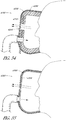
- Figure 14 illustrates a mask assembly 1100 that is similar to or the same as the previous mask of Figures 12 and 13 , with a heating element 1110 (e.g., heated copper wire) extending into the insulation space 1102 between the layers of the mask assembly 1100.
- the heating element can extend from the breathing tube 1120.
- the heating element 1110 can heat the air inside the insulation space 1102, providing a heat barrier to the fluids inside the mask from the relatively colder outside air, thus reducing condensation within the inner layer of the mask.
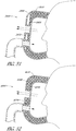
- Figure 15 illustrates a mask assembly 1200 that is similar to or the same as the previous masks of Figures 12-14 except the vent holes 1204 extend from the interior layer 1206 to the exterior layer 1208.
- the warmer air in the insulation space 1202 can go around the vent holes 1204 and keep them warm and reduce condensation.
- Figure 16 illustrates a mask assembly 1300 that is similar to or the same as the double layer mask assembly of Figure 12 except the vent holes 1304 are on the exterior layer 1308 of the mask assembly 1300.
- Figure 17 illustrates a mask assembly 1400 that is similar to or the same as the mask assembly of Figure 16 except the vent holes 1404 are long and extend the length of the two layers of the mask assembly. As explained before for Figure 15 , the warmer air in the insulation space 1402 can go around the vent holes 1404 and keep them warm and reduce condensation.
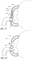
- fluids can enter the interior of the mask and travel through the insulation space 1502 before exiting out the mask.
- the fluids can travel through vent holes 1504 in the interior layer 1506 into the insulation space 1502 and through exhaust holes 1505 in the exterior layer 1508 of the mask assembly 1500.
- the vent holes 1504 of the interior layer 1506 and the exhaust holes 1505 of the exterior layer 1508 are aligned with one another. By traveling through the insulation space 1502, the fluids are kept warmer which can help reduce condensation.
- fluids enter the interior of the mask and exit out through vent holes 1604 in the interior layer 1606 into the insulation space 1602.
- the fluids can travel through the insulation space 1602 and exit the mask assembly 1600 through exhaust holes 1605 in the exterior layer 1608.
- the exhaust holes 1605 can be at the sides of the mask assembly 1600 and positioned all around the circumference of the mask assembly.
- the vent holes 1604 of the interior layer 1606 may not be aligned with the exhaust holes 1605 of the exterior layer 1608.
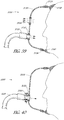
- the mask assembly 1700 illustrated in Figure 20 is essentially the reverse of the previous mask assembly of Figure 19 . Fluids can enter the insulation space 1702 from the interior of the mask via vent holes 1704 disposed around the circumference of the interior layer 1706 of the mask and can exit the insulation space 1702 via exhaust holes 1705 on the exterior layer 1708 of the mask.
- Figures 21-24 illustrate double mask assemblies in which the second layer is partially or completely detachable from the main part (e.g., first layer) of the mask.
- the second layer 1808 has a small protrusion 1807 that couples with a clip 1809 (e.g., a snap fit configuration) in the first layer 1806.
- the second layer 1808 can form an airtight or substantially airtight seal with the first layer 1806.
- the second layer 1808 does not necessarily create an airtight seal with the first layer 1806.
- This detachable system can be employed with any of the double mask assemblies described above or elsewhere herein. By being able to detach the second layer it can advantageously be easier to clean the mask and remove water that is trapped between the layers.
- the mask assembly 1900 of Figure 23 is similar to the mask assembly of Figures 21 and 22 , but with a different coupling mechanism.
- the mask assembly 1900 does not have a protrusion and clip to attach the second layer 1908 to the first layer 1906. Instead, the second layer 1908 has a tube connection 1907 that can clip or otherwise couple onto the first layer 1906.
- the mask assembly 2000 of Figure 24 is similar to the mask assembly of Figure 23 except the coupling mechanism comprises a connection 2007 on the second layer 2008 which clips or otherwise couples into the first layer 2006 of the mask assembly near the vent holes 2004.
- the connection 2007 can provide a pathway for the fluid exiting the vent holes 2004.
- Figures 25 and 26 illustrate mask assemblies 2100 incorporating a water vapor breathable membrane layer 2130.
- the membrane layer comprises a water impermeable material which is substantially air permeable.
- the membrane layer can be a single material or a composite of several layers of material.
- the material can be non-woven or woven.
- the membrane layer 2130 can be positioned within the mask assembly 2100 between the mask frame 2106 and the patient's face.
- the membrane layer 2130 does not permit water to pass through the material in liquid form, but permits water vapor to pass through.
- the membrane layer 2130 can inhibit or prevent water condensate on the outer side of the membrane layer (i.e., between the mask frame 2106 and membrane layer 2130) from passing through the membrane layer and dripping onto the patient's face.
- Figures 27-32 and 43 illustrate mask assemblies incorporating a water vapor breathable material layer or membrane, which can be a single layer of material or a composite of multiple layers of material.
- the breathable membrane layer 2230 can comprise a membrane clamped, clipped-on or otherwise secured onto a small tube 2232 made of plastic or other rigid material.
- the small tube 2232 can couple to a mask frame 2206 or rigid shell layer, which can then be connected to the breathing tube 2220.
- the breathable membrane layer 2230 can also have a perimeter structure 2234 that is a rigid or relatively rigid material (e.g., plastic) attached to the exterior perimeter of the membrane material.
- the perimeter structure 2234 can be configured to couple to a mask seal 2240 (e.g., silicone seal) on one side and a mask frame 2206 (e.g., polycarbonate shell or other suitable rigid material) on the other side.
- the mask frame 2206 can have vent holes 2204 to allow passive air ventilation while maintaining its rigidity so that the shape and structure of the mask assembly is preserved, giving protection to the breathable membrane layer 2230.
- Figures 29 , 31 , 32 and 43 illustrate mask assemblies 2300 incorporating double layers of water vapor breathable membranes or other water vapor breathable layers.
- the water vapor breathable membranes can be similar to or the same as in the mask assemblies of Figures 27 and 28 .
- the illustrated mask assemblies 2300 can have a second membrane layer 2336, which can provide insulation and water vapor breathability to the exterior surface of the mask assembly 2300.
- the second membrane layer 2336 is a foamed water vapor breathable membrane layer. By being foamed, the water vapor breathable membrane can be more rigid and can form a robust exterior structure for the mask assembly.
- the second membrane layer 2336 has a perimeter structure 2337 that is a rigid or relatively rigid material (e.g., plastic) attached to the exterior perimeter of the second membrane layer.
- the second membrane layer 2336 can also have a small tube 2338 made of plastic or other rigid material that can connect to the breathing tube.
- the first membrane layer 2330 can connect to the second membrane layer 2336.
- the foamed water breathable material 2436 can also be extruded into a ribbed shape ( Figures 31 and 32 ) to allow extra surface area for water to evaporate off of and provides additional strength and rigidity.
- Figure 43 illustrates a configuration with two membrane layers 2530 that provide insulation to the mask assembly 2500 as well as water vapor breathability.
- Figure 30 illustrates a mask assembly 2600 having a window(s) or a cut-out portion(s) 2608 covered by a breathable material 2630 (e.g., a water vapor breathable membrane). If desired, multiple layers of a breathable material can be employed.
- a breathable material 2630 e.g., a water vapor breathable membrane
- Figures 33-34 illustrate mask assemblies that make use of Bernoulli's principle to actively flow air over the surface of the water vapor breathable material to reduce condensation and Figures 35-38 illustrate vents that permit air to be drawn into or otherwise enter the mask assembly to reduce condensation.
- the mask assembly 2700 is composed of mostly rigid material (e.g., polycarbonate or other plastics) except for a water vapor breathable membrane layer 2730 which divides the mask assembly into two chambers. Fluids can leave the mask assembly 2700 through recessed vent holes 2704, which can be made of rigid material and clamped, glued, or otherwise attached to the water vapor breathable membrane layer 2730.
- the fluids can flow out to the environment via a cutout 2705 or other vent holes or exits in the outer shell 2708, which can be made of a rigid plastic.
- Water vapor can pass through the water vapor breathable membrane 2730 and into the intermediary chamber 2702 (space between the water breathable membrane layer 2730 and the outer shell 2708) instead of condensing on the interior surfaces.
- entrainment holes 2709 around the perimeter of the outer shell 2708 can suck air in from the environment due to Bernoulli's principle and actively dry the water vapor breathable membrane layer 2730 by moving through the intermediary chamber 2702, and exit through the cutout 2705 near the vent holes 2704.
- Figures 35 and 36 illustrate a mask assembly 2800 with a water vapor breathable membrane layer 2830 and an outer shell 2808.
- the outer shell 2808 forms a pathway leading from the recessed vent holes 2804 to the environment.
- the exterior side of the breathable membrane layer 2830 can be dried passively by air entering the intermediary chamber 2802 through drying holes 2809.
- the mask assembly 2900 of Figure 37 is similar to the mask of Figure 36 except the vent holes 2904 are not recessed but instead extend from the water vapor breathable membrane layer 2930 to the outer shell 2908.
- Figure 38 illustrates another configuration of a mask assembly 3000 with vent holes 3004 clamped or otherwise coupled to the water vapor breathable membrane layer 3030. Fluids can pass through the vent holes 3004 and into the intermediary chamber 3002. The fluids can then exit the mask assembly 3000 via exhaust holes 3005 around the perimeter of the outer shell 3008.
- Figures 39-42 illustrate mask assemblies in which a substantial portion or the majority of the mask assemblies are made out of foamed water vapor breathable membrane material with rigid materials on certain portions of the mask assemblies.
- Figure 39 illustrates a configuration of such a mask assembly 3100.
- a perimeter structure 3134 preferably made of rigid material (e.g., polycarbonate or other plastics), can be clamped or otherwise attached to the breathable membrane 3130 at the perimeter.
- a seal 3140 e.g., silicone
- a connection tube 3132 made of for example rigid plastic, can also be clamped or otherwise attached to the breathable membrane 3130 and configured to couple to the breathing tube 3120.
- Another rigid piece with vent holes 3104 can also be clamped or otherwise attached to the breathable membrane 3130.
- Figure 40 illustrates another configuration of a mask assembly 3200 with foamed water vapor breathable membrane 3230 that is similar to the mask of Figure 39 .
- the vent holes 3204 are not in a separate piece of rigid material but instead built into the connection tube 3232 to the breathing tube 3220.
- Figure 41 illustrates a mask assembly 3300 with breathable membrane 3330 that is similar to the mask assemblies of Figure 39 and 40 , except the vent holes 3304 are located all around the perimeter of the mask assembly in the perimeter structure 3334.
- Figure 42 illustrates a mask assembly 3400 that is similar to the mask assembly of Figure 39 except the foamed water vapor breathable membrane 3430 is extruded or otherwise formed to be ribbed, thus providing additional surface area for water to evaporate off of.
- the vent holes 3404 are disposed on a rigid piece that is attached to the breathable membrane 3430.
- Figures 44-47 illustrate mask assemblies and portions thereof incorporating hydrophobic and/or hydrophilic materials, coatings or inserts.
- the interior 3552 of the vent holes and, optionally, just at the edge of the vent holes 3504 can be covered in a hydrophobic coating and the surrounding area 3554 of the vent holes can be covered in a hydrophilic coating.
- This configuration can encourage or facilitate water to move away from the vent holes 3504 and move to the surrounding areas 3554, thereby helping to inhibit or prevent the vent holes 3504 from being clogged up with water.
- the hydrophobic coating is very hydrophobic whereas the hydrophilic coating can be only slightly hydrophilic so that water is drawn away from the vent holes but does not accumulate too much water.
- Figures 45 and 46 illustrate portions of a mask assembly 3600 with hydrophobic inserts 3652 placed into the vent holes 3604 and hydrophilic inserts 3654 placed around the vent holes 3604.
- Figure 46 is a cross-section view of the inserts of Figure 45 .
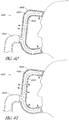
- Figure 47 illustrates another configuration of a mask assembly 3700 in which the vent holes 3704 are peaks and the surrounding area 3754 are depressions.
- the vent holes 3704 can be hydrophobic and the surrounding area 3754 can be hydrophilic.
- the peaks of the vent holes 3704 can allow any accumulated condensation to roll down into the hydrophilic region where the water will be away from the vent holes 3704 and not occlude them.
- the hydrophilic region can also be designed as channels to carry water further away from the vent holes.
- a mask assembly that has extra insulation can be used to reduce, prevent or compensate for condensation.
- a mask assembly with extra insulation could also include a mask assembly with a removable soft material cover. Accordingly, the mask assembly can (as an alternative or in addition to other condensation reducing or compensating configurations) incorporate a material (e.g., insulation) layer, which can be permanently or removably secured to the base mask.
- Figure 50 illustrates a mask assembly 3800 with an insulating layer 3860 (e.g., a soft fabric cover) that can attach onto a rigid mask frame 3806.
- the insulating layer 3860 can be attached using any of a variety of coupling mechanisms 3862, including Velcro® patches, buttons, clasps, zips, string, elastic or other suitable coupling configurations.
- the insulating layer 3860 can provide any one or combination of additional insulation, a better tactile feel to the mask, as well as the ability to add colours/patterns to the mask assembly.
- Figure 51 illustrates a multi-layer mask assembly 3900 with a phase change material 3970 between the layers 3906, 3908.
- the phase change material 3970 can be completely sealed off from the rest of the mask to prevent contaminants entering the phase change material or phase change material leaking out.
- the phase change material 3970 can be a hydrated salt or salt-based solution which has well defined phase change temperatures and good thermal conductivity.
- suitable phase change materials include, but are not limited to: PCM-HS34PEES or PCM-HS29P as sold by RGEES LLC, and MPCM32 or MPCM28 as sold by Microtek Laboratories, Inc.
- the phase change material is able to be heated safely in a microwave. Other heating methods may be employed by the user to heat the phase change material.
- the multi-layer mask assembly containing the phase change material can be heated before use so that the phase change material changes phase, such as melting from a solid to a liquid.
- the phase change material absorbs heat as it changes phase to liquid.
- the phase change material can subsequently cool until it reaches its phase change temperature and maintain this temperature until all of the material solidifies once again. Only then will the temperature of the phase change material drop below its phase change temperature.
- the period during which the phase change material is changing phase from liquid back to solid is the period during which the phase change material can be used to maintain the mask assembly at a warm temperature, preventing condensation from forming.
- the phase change material can change phase between liquid to solid within the range of 29-35 degrees. This range allows the mask assembly to remain warm enough to at least partially prevent condensation but not so hot as to be uncomfortable to the wearer of the mask assembly. Other temperature ranges are also envisaged.
- the phase change material can have a high latent heat and, preferably, there is enough of the phase change material provided between the mask layers to allow at least about a 6 hour period (preferably more than 8 hour period) during which the phase change material maintains its temperature before completely solidifying. This allows the phase change material to heat the mask for the majority of a night or typical sleeping period. The time period that temperature is maintained can also be prolonged by adding extra insulation to the exterior of the mask assembly to slow the energy loss to the environment.
- the mask assembly 3900 can have a small air gap 3972 or other accumulator within the phase change material layer so as to accommodate the increased volume of the phase change material as it changes phase.
- Figure 52 illustrates a multi-layered mask assembly 4000 with supercooled phase change materials 4070 such as sodium acetate enclosed between its layers 4006, 4008.
- the mask assembly 4000 can be heated to melt the phase change material 4070. As it returns to room temperature the phase change material 4070 naturally supercools without solidification or crystallization occurring.
- the patient uses the mask assembly 4000 to go to sleep, they would, for example, press an activation button 4074 to initialize a seed crystal within the phase change material 4070 to form. This would cause a chain reaction, causing the rest of the phase change material to rapidly solidify and begin to release heat.
- the heat can reduce or prevent condensation occurring on the mask assembly 4000.
- the mask can be reused by reheating the mask assembly, such as placing it in boiling water, to melt the phase change material 4070.
- Figure 53 illustrates a multi-layered mask assembly 4100 where the second layer 4108 can be detached from the first layer 4106 (i.e., main part) of the mask and a heat pad 4170 can be disposed between the layers.
- the heat pad 4170 can consist of a phase change material as described above, encapsulated in an appropriate material or bag, or it could be a reversible or irreversible chemical based heat pad, or other suitable heat-producing configuration. In some configurations, the heat pad 4170 can be removable and/or replaceable.
- Chemical based heat pads are commonly used to treat sports injuries (such as those sold by http://www.beyondbodiheat.com/Products.aspx). Some heat pads contain iron powder, which when exposed to air cause oxidization to occur and generate heat. These heat pads can produce heat for a long period of time, such as BodiHeat® which generates heat for approximately 12 hours. These heat pads can provide sufficient heat for the duration of a night, but are single use products and need to be replaced every use.
- Figures 54-58 illustrate mask assemblies comprising of thermally conductive materials.
- a mask assembly 4200 comprises two layers, which can be made of materials such as plastic.
- the outer layer 4208 can be a conventional insulating layer made of for example plastic, such as polycarbonate.
- the inner layer 4206 can be a thermally conductive polymer such as those sold by Cool Polymers, Inc. (www.coolpolymers.com).
- the thermally conductive inner layer 4206 can be warmed by contact with the patient's skin, or by the hot gases emitted by the CPAP device or the patient's lungs.
- this mask assembly can comprise a heating element 4210, such as a coiled conductive (e.g., copper) wire in-moulded into one or both of the inner layer 4206 and the outer layer 4208 and extend out of the mask assembly.
- the heating element 4210 can be electrically charged to produce heat and further warm the mask interior preventing condensation from forming.
- the thermally conductive inner layer 4306 is a thin layer of conductive metal, such as aluminum or other suitable material.
- the properties of this mask assembly 4300 can be similar to the design illustrated in Figure 54 but may require less material and be thinner as conductive metals are often more thermally conductive than thermally conductive plastics. However, this mask assembly 4300 configuration may be more difficult and/or expensive to manufacture, and to ensure that the metal layer is held firmly in place by the insulating outer layer 4308.
- Figure 56 illustrates a heating element 4410, such as a coiled and electrically insulated wire, that is attached to the inner layer 4406 (e.g., conductive metal material) of the mask assembly 4400.
- An insulating outer layer 4408 can be coupled to the inner layer 4406.
- the heating element 4410 can be electrically charged to produce heat.
- the conductive inner layer 4406 allows the heat to spread through the mask's surface, reducing or preventing any cold patches or areas of the mask assembly 4400 that the heat from the heating elements cannot reach. With the interior of the mask heated in this manner, less condensation may form.
- a mask assembly 4500 is illustrated with a patch of the inner layer 4506 exposed through the outer layer 4508.
- a heating element 4510 such as an insulated copper wire can be coiled and densely packed onto the surface of the exposed inner layer 4506. When an electrical charge heats the heating element 4510, the heat can spread through the conductive inner layer 4506 to a substantial portion of or, preferably, the entirety of the inner layer 4506.
- a sensor 4580 such as an electrical thermometer, can be placed inside the mask and its measurements can be used in a feedback loop to intelligently control the electrical current sent to the heating element 4510 in order to maintain the inner mask temperature to be above dew point but not so hot as to become uncomfortable to the wearer of the mask assembly.
- a mask assembly 4600 is shown with an outer layer 4608 and an inner layer 4606 with conductive material that can be heated through the use of a thermoelectric cooling device 4610, such as a Peltier cooler.
- the thermoelectric cooling device 4610 can be placed on the conductive inner layer 4606 so that its hot side is against the conductive material and the cold side is against the air.
- the cold side can be attached to a heat sink 4612. This can encourage the cold side to return to room temperature faster, thus increasing the efficiency of the thermoelectric cooling device 4610.
- a sensor 4680 such as an electrical thermometer, can be on the interior surface of the inner layer 4606 of the mask and its readings can be used to control the power sent to the thermoelectric cooling device 4610. This creates a feedback loop that can allow varying currents or no current at all to be sent to the thermoelectric cooling device to ensure the mask interior remains above the dew point but does not become so hot as to become uncomfortable for the wearer of the mask.
- the mask assembly can comprise an insulation layer.
- the mask assembly 4700 can have an insulation layer 4730 made of for example foamed plastic.
- the foamed plastic can be formed using a direct injection expanded foam molding process, which is a foam manufacturing process that can create closed-cell foam products direct from compound to final insulation layer.
- vent holes 4704 can be integrally formed during the direct injection expanded foam molding process, or formed separately from the process.
- the insulation layer can be made of other suitable insulated materials, such as rubber or textiles.
- the mask assembly can have an inner layer that diffuses the fluids entering the mask assembly from the gas delivery system.
- the fluids entering the mask assembly 4800 through the breathing tube 4820 travel into the intermediary chamber 4802, which is the space between the inner layer 4806 and the outer layer 4808.
- the inner layer 4806 obstructs direct flow to the patient so the fluids can flow around the inner layer 4806.
- the inner layer 4806 can be heated by the fluids from the gas delivery system, which are usually at a higher temperature than ambient air. The heated inner layer 4806 can help reduce the formation of condensation in the mask assembly.
- the mask assembly 4900 illustrated in Figure 61 is similar to the mask assembly of Figure 60 , except the inner layer 4906 comprises one or more holes. Similar to as described above, the fluids entering the mask assembly 4900 through the breathing tube 4920 travel into the intermediary chamber 4902 between the inner layer 4906 and the outer layer 4908. The inner layer 4906 obstructs direct flow to the patient so the fluids can flow around the inner layer 4906 and through the holes in the inner layer 4906. The inner layer 4906 can be heated by the fluids flowing around and through the inner layer 4906. The heated inner layer 4806 can help reduce the formation of condensation in the mask assembly.
- vent holes can be replaced or supplemented with elongated holes or slits to inhibit or prevent the holes from clogging with water from condensation.
- the invention may also be said broadly to consist in the parts, elements and features referred to or indicated in the specification of the application, individually or collectively, in any or all combinations of two or more of said parts, elements or features.
Description
- The present disclosure relates generally to respiratory therapy systems. In particular, the present disclosure relates to patient interfaces, such as mask assemblies and breathing circuits, with condensation reducing or compensating configurations.
- CPAP therapy, commonly used to treat obstructive sleep apnea, pumps air to a patient to maintain a minimum pressure in the airways. Often the air is heated and humidified before being sent to the patient. This causes less dryness and irritation to the patient and can increase compliance in the therapy. An issue with humidified air is that it can condense into water, becoming rainout. This is due to the heated air cooling down and the air reaches a dew point, causing condensation.
- Rainout can cause several problems, including the following: the water can restrict airflow to the patient or out of the mask; water can form into droplets and drip on a patients face which can wake them; a whistling noise can result when water forms on the vent holes; water can disrupt the mask seal against the patient's face; the patient may wake with a wet face which can feel unpleasant.
- If a patient is unhappy with the rainout in their mask, they may reduce the humidification settings in their CPAP or turn off humidification entirely. Other advice to reduce rainout is to increase the temperature of the bedroom so that there is a smaller temperature drop between the humidified air and the ambient air of the room and thus less water will condense.
- Relevant prior art includes
GB 2 470 804 -
US 2011/232646 A1 is also relevant prior art and discloses a mask with a filter for the gases provided to patient. It discloses ventilation holes that allow gases to flow in or out of an intermediated chamber and a filter between the users face and the outer surface of the mask. - To prevent rainout in breathing tubes there are several technologies used in CPAP tubing, such as the heated breathing tube and insulating covers that can go over the tubes. However there are currently no technologies and little in the state of the art to prevent condensation at the mask region. One or more of the disclosed masks, breathing circuits or related components address the issue of condensation at the mask.
- Mask assemblies, breathing circuits and related components described herein include configurations for reducing condensation within the mask and/or inhibiting or preventing condensation from coming into contact with a user of the mask. The mask assemblies can incorporate heating elements (such as heating coils), insulating spaces or barrier layers.
- The systems, methods and devices described herein have innovative aspects, no single one of which is indispensable or solely responsible for their desirable attributes. Without limiting the scope of the claims, some of the advantageous features will now be summarized.
- The present invention provides a patient interface as claimed. Preferable features are shown in the dependent claims. In accordance with at least one of the embodiments disclosed herein, a patient interface is provided comprising a body adapted to form a seal with a user's face, a coupling for fluid connection to a gas delivery system, a water vapor breathable membrane layer, and an outer layer with holes that allows gases to flow into an intermediary chamber between the water vapor breathable membrane layer and the outer layer. The patient interface is configured such that the water vapor breathable membrane layer is positioned between the user's face and the outer layer and inhibits or prevents water condensate in the intermediary chamber from passing through the water vapor breathable membrane layer and dripping onto the user's face in use
- In some configurations, the patient interface further comprises a vent that allows a flow of gases from an interior of the body to an exterior of the body. The vent can be configured so that the flow of gases entrains air from the environment into the intermediary chamber. In some configurations, the vent comprises a hydrophobic material and an area adjacent the vent can comprise a hydrophilic material.
- The holes on the outer layer can be disposed at or near the perimeter of the outer layer. In some configurations, the body comprises a silicone seal member.
- A patient interface is described but not claimed comprising a body adapted to form a seal with a user's face, the body comprising an inner layer, an outer layer, and an insulation space between the inner and outer layers. The patient interface can comprise a coupling for fluid connection to a gas delivery system.
- In some examples not claimed, the patient interface further comprises a heating element disposed in the insulation space.
- The patient interface can further comprise a vent that allows a flow of gases from an interior of the body to an exterior of the body. The vent can be recessed and disposed adjacent the inner layer. The insulation space can be in fluid communication with the vent. The body can be configured so that the flow of gases flows through the insulation space before exiting the interface.
- In some examples not claimed, the outer layer is releasably attached to the inner layer. The patient interface can further comprise at least one heat pad coupled to the outer layer.
- In some examples not claimed, the patient interface further comprises a phase change material in the insulation space.
- The inner layer can be configured to diffuse gases from the gas delivery system and can be heated by the gases.
- A patient interface is described but not claimed comprising a foamed breathable membrane body that allows water vapor to pass through the body, a frame structure attached to the foamed breathable membrane body, and a coupling for fluid connection to a gas delivery system.
- In some examples not claimed, the patient interface further comprises a water vapor breathable layer. The patient interface can further comprise a vent that allows a flow of gases from an interior of the interface to an exterior of the interface. The patient interface can further comprise a seal adapted to form at least a substantial seal with a user's face.
- In some examples not claimed, the foamed breathable membrane body may be ribbed.
- A patient interface is described but not claimed comprising a body adapted to form a seal with a user's face, the body comprising an inner layer made of a thermally conductive material and an outer layer made of an insulating material. The patient interface can further comprise a coupling for fluid connection to a gas delivery system.
- In some examples not claimed, the patient interface further comprises a vent that allows a flow of gases from an interior of the body to an exterior of the body.
- In some examples not claimed, the patient interface further comprises a heating element in thermal communication with the inner layer. The thermally conductive material can be a polymer. The thermally conductive material can be a metal.
- In some examples not claimed, the patient interface further comprises a thermoelectric cooling device in thermal communication with the inner layer. The patient interface can further comprise a sensor to provide feedback of the temperature of the inner layer.
- The drawings are provided to illustrate example embodiments described herein and are not intended to limit the scope of the disclosure.
-
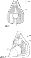
FIGS. 1-2 are front views of mask assemblies with heating elements winding through the mask, according to embodiments of the present disclosure. -
FIG. 3 is a front view of a mask assembly with a loop of heating element, according to an embodiment of the present disclosure. -
FIG. 4 is a close-up perspective view of a section of a heating element, according to an embodiment of the present disclosure. -
FIG. 5 is a side view of a breathing circuit with a heating element, according to an embodiment of the present disclosure. -
FIG. 6 is a side view of a cover for a breathing tube, according to an embodiment of the present disclosure. -
FIG. 7 is a side view of the cover ofFIG. 6 attached to the breathing circuit ofFIG. 5 . -
FIGS. 8-10 are cross-sectional side views of connections between mask assemblies and breathing tubes, according to various embodiments of the present disclosure. -
FIG. 10A is a front sectional view of the breathing tube ofFIG. 10 . -
FIG. 11 is a cross-sectional side view of a connection between a mask assembly and a breathing tube, according to another embodiment of the present disclosure. -
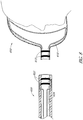
FIG. 12 is a cross-sectional side view of a double layer mask assembly, according to an embodiment of the present disclosure. -
FIG. 13 is a side perspective view of a double layer mask assembly, according to an embodiment of the present disclosure. -
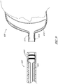
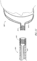
FIGS. 14-24 are cross-sectional side views of double layer mask assemblies, according to various embodiments of the present disclosure. -
FIG. 25 is a front view of a mask assembly with a breathable membrane layer, according to an embodiment of the present disclosure. -
FIGS. 26 and27 are cross-sectional side views of mask assemblies with breathable membrane layers, according to various embodiments of the present disclosure. -
FIG. 28 is a front view of the mask assembly ofFIG. 27 . -
FIG. 29 is a cross-sectional side view of a mask assembly with multiple membrane layers, according to an embodiment of the present disclosure. -
FIG. 30 is a front view of a mask assembly with a cut-out portion, according to an embodiment of the present disclosure. -
FIG. 31 is a cross-sectional side view of a mask assembly with a ribbed membrane layer, according to an embodiment of the present disclosure. -
FIG. 32 is a front view of the mask assembly ofFIG. 31 . -
FIG. 33 is a front view of a mask assembly that entrains air, according to an embodiment of the present disclosure. -
FIG. 34 is a cross-sectional side view of the mask assembly ofFIG. 33 . -
FIG. 35 is a front view of a mask assembly with passive drying, according to an embodiment of the present disclosure. -
FIG. 36 is a cross-sectional side view of the mask assembly ofFIG. 35 . -
FIGS. 37 and 38 are cross-sectional side views of mask assemblies, according to various embodiments of the present disclosure. -
FIGS. 39-42 are cross-sectional side views of mask assemblies with foamed breathable membranes, according to various embodiments of the present disclosure. -
FIG. 43 is a front view of a mask assembly with two membrane layers, according to an embodiment of the present disclosure. -
FIG. 44 is a close-up cross-sectional side view of vent holes with hydrophobic and hydrophilic coatings, according to an embodiment of the present disclosure. -
FIG. 45 is a perspective view of a mask assembly with hydrophobic and hydrophilic inserts, according to an embodiment of the present disclosure. -
FIG. 46 is a close-up cross-sectional side view of the inserts ofFig. 45 . -
FIG. 47 is a close-up cross-sectional side view of vent holes with peaks and depressions, according to an embodiment of the present disclosure. -
FIG. 48 is a cross-sectional side view of a mask assembly with a generator, according to an embodiment of the present disclosure. -
FIG. 49 is a front view of a mask assembly with a circuit board, according to an embodiment of the present disclosure. -
FIG. 50 is an exploded cross-sectional side view of a mask assembly with retaining mechanisms, according to an embodiment of the present disclosure. -
FIGS. 51-53 are cross-sectional side views of mask assemblies with phase change materials, according to various embodiments of the present disclosure. -
FIGS. 54-55 are cross-sectional side views of mask assemblies with thermally conductive materials, according to various embodiments of the present disclosure. -
FIG. 56 is a close-up cross-sectional side view of a mask assembly with a heating element and layers, according to an embodiment of the present disclosure. -
FIGS. 57-58 are cross-sectional side views of mask assemblies with heating elements and sensors, according to various embodiments of the present disclosure. -
FIG. 59 is a cross-sectional side view of a mask assembly with an insulation layer, according to an embodiment of the present disclosure. -
FIGS. 60-61 are cross-sectional side views of mask assemblies with diffusers, according to various embodiments of the present disclosure. -
Figures 1 and 2 illustrate interfaces, specifically maskassemblies 100, comprisingheating elements 110, such as for example heating coils. Theheating elements 110 can be moulded into the mask as in the illustrated configuration, or otherwise secured to the mask such as through adhesives, clips, welding or the like. In some configurations, the heating elements are attached to the inner surface of the mask. Theheating elements 110 can wind throughout a substantial portion or all of the mask's inner surface. Preferably the heating elements are sufficiently distributed on the surface area of the mask to evenly or substantially evenly heat the interior space of the mask. - The
heating elements 110 can be powered by the electrical current from the CPAP or other flow generator/humidifier system. Power can be supplied directly to themask assembly 100 such as via a separate power line. In some configurations, the power can be conveyed through another component of the system, such as thebreathing tube 120 or circuit, for example. -
Figures 48 and49 illustrate mask assemblies comprising heating elements with alternative or auxiliary power configurations for powering the heating elements. With reference toFigure 48 , heating elements 210 (e.g., copper wire or other conductive material) is heated with current produced in asmall generator 212 in themask assembly 200. Thegenerator 212 can comprise any suitable configuration, such as a small fan and motor placed in the mask so that airflow from the CPAP (or other flow generator) will cause the fan blades to rotate (or otherwise power the generator). The rotation will produce an electrical current that passes through theheating element 210. -
Figure 49 illustrates amask assembly 300 with in-moulded heating elements 310 (e.g., copper coils or other conductive material) that form a circuit with acircuit board 312 attached to a suitable location (e.g., the exterior) of the mask. Thecircuit board 312 can contain abattery 314 to power theheating element 310 with current and, optionally, a microcontroller and/or sensors (such as a temperature sensor) to allow smart control of theheating element 310. -
Figure 3 illustrates amask assembly 400 having one or more loops ofheating element 410. The one or more loops ofheating element 410 can be clamped in place by aretaining mechanism 412, such as plastic hooks or tabs, similar to the ones used to connect the mask strap to the mask in the GLIDER™ strap configurations used in the FLEXIFIT™ series nasal masks sold by Fisher & Paykel Healthcare. For example, a suitable configuration is disclosed in international patent publication numberWO2011/077254 A2 , especially inFigure 27 . The heating element can be of any suitable construction, such as the same as or similar to that used in theEvaqua 2™ breathing circuit sold by Fisher & Paykel Healthcare.Figure 4 illustrates a section of an example of asuitable heating element 410, which comprises a core 414 with conductive coil 416 (e.g., copper) wound around it, and anouter cover 418 around the core. In some configurations, the core can be made of string and the outer cover can be a plastic tube. - Although the illustrated interfaces are full face masks, the scope of the present disclosure should not be limited by the particular embodiments described. The interfaces can comprise any of a plurality of different types of suitable mask configurations. For example, certain features, aspects and advantages of the present invention can be utilized with nasal masks, full face masks, oronasal masks or any other positive pressure mask.
-
Figures 5-11 illustrate breathing circuits, masks and related components for heated mask assemblies. With respect toFigure 5 , abreathing tube 520 can have at least one length of heating element 510 (e.g., coiled heating wire) disposed inside the tube, which can extend at least partially outside the tube. The portion of the heating element that extends outside the tube can be clipped into a mask and used as a heating element for the mask, as described previously forFigure 3 . In the illustrated configuration, a loop ofheating element 510 is configured to be positioned in the interior of the mask with the end portions of the heating element being positioned outside of the mask. In other configurations, a single length of heating element can have conducting wires creating a circuit, or multiple lengths or loops of heating elements can be provided to be positioned into the mask. - With respect to
Figures 6 and 7 , acover 522 can be placed at the end of thebreathing tube 520 so that the portion ofheating element 510 extending outside thebreathing tube 520 is contained when a non-heated mask is to be connected to thebreathing tube 520. Thecover 522 can have two tapered connections. At one end thecover 522 can be tapered to connect onto thebreathing tube 520 and the other end can be tapered to connect onto the mask. Aclip 524 can be disposed on the interior of thecover 522 so that theheating element 510 can be clipped and held in place within thecover 522. The clip can be made of plastic, metal, or other suitable material and can be moulded, welded, adhered, or otherwise attached to the cover. An embodiment of acover 522 is shown by itself inFigure 6 and coupled to abreathing tube 520 inFigure 7 . - With respect to
Figure 8 , thebreathing tube 620 can have two ormore rings 622 exposed on its interior that are made of for example copper, silver or other conductive material. The breathing tube rings 622 can be in electrical communication withconductive wires 624 that extend inside the tube. In some configurations, thewires 624 can be partially disposed within the tube's wall and connected to the outer surface of the breathing tube rings 622. In some configurations, the conductive wires can be at least partially made of a heating element material to help regulate condensation in the tube. Thebreathing tube 620 can be configured to couple with amask assembly 600 having two or more mask rings 612 that lie exposed on the outside surface of themask assembly 600. The breathing tube rings 622 can come into contact with the mask rings 612 when thebreathing tube 620 is coupled to themask assembly 600 to form an electrical connection. The mask rings 612 can be connected towires 610, which may be at least partially made of heating elements, which extend to the interior of themask assembly 600. Thewires 610 can be connected to the interior surface of the mask rings 612, allowing thebreathing tube 620 to rotate in relation to themask assembly 600 while still maintaining an electrical connection. -
Figure 9 illustrates a similar configuration as the embodiment inFigure 8 , except with abrush connection 614 on themask assembly 600 side of the connection. In some configurations, the brush connection can be on the tube side of the connection and the mask assembly side can have a ring. Thebrush connection 614 can comprise a conductive brush (e.g., copper brush) that is exposed, or a protrusion with conductive material (e.g., copper) that can come into contact with the connecting ring to make an electrical contact between the two connections. - With respect to the
breathing tube 720 and mask assembly 700 ofFigure 10 , two or more half rings 722 and two ormore brushes 714 can be employed. This is a simpler connection and advantageously requires less conductive material compared to full rings.Figure 10A illustrates a view of the end of thebreathing tube 720 showing the half rings 722 and theconductive wires 724 extending from the half rings. Such a configuration may not be preferred in certain applications because if thebrushes 714 are positioned exactly at the point where a gap exists between the half rings 722, the electrical connection could be lost until the connection is made again. However, in some applications, this position may be unlikely to occur or, if it occurs, is unlikely to occur for a significant period of time. - With respect to
Figure 11 , electromagnetic induction can also be used to transmit energy to themask assembly 800 and induce a current. By winding conductive wires tightly around the connection at thebreathing tube 820, the current in thetube windings 822 can induct a magnetic field. Themask assembly 800 can havemask windings 812 that induce electrical current when the mask windings are positioned in the magnetic field produced by thetube windings 822, such as when thebreathing tube 820 is connected to themask assembly 800. In such configurations, the power source preferably is either a time-varying current or an alternating current (AC) in the tube and not DC. - In some configurations, the mask assembly can comprise reusable portions and disposable portions. For example, a reusable portion can comprise of one or more heating elements or coils of heater wire that can be over-moulded onto the reusable portion. Electrical connections can be configured to be connected to a heated breathing tube's wiring. The reusable portion of the mask assembly can couple onto the rest of the mask assembly, such as the mask seal or elbow, which may be disposable portions. Since the portion of the mask assembly containing heating elements is usually a more expensive component, it can be reused whereas other portions of the mask assembly can be disposable after a single use or for short term use (days, weeks, or months). This would be desirable in hospital usage, such as for patients requiring breathing support, as masks are designed to be single use only. With this configuration, portions of the mask assembly can still be kept disposable for sanitary reasons, but the high cost parts can be cleaned and reused. This allows a high cost part to be integrated with the mask system while reducing overall costs.
-
Figures 12-20 illustrate various configurations of a multi-layer mask, which is embodied as a double-layer mask assembly in the illustrated configurations. However, in other configurations, the mask can include more than two layers (e.g., three, four or more layers). In some configurations, air from the interior of the mask passes through a second chamber (insulation or transition space) defined between a first layer and a second layer (or other layers in a mask having more than two layers) before exiting the mask. The insulation or transition space provides insulation to the interior of the mask. - With respect to
Figures 12 and13 , themask assembly 1000 can have two or more layers made of for example plastic, wherein aninsulation space 1002 or transition space is defined by the space between the layers, which can be substantially or completely sealed from the interior and exterior of the mask. Theinsulation space 1002 can be filled with air or any other suitable gas or other medium that preferably provides an insulating function, such as a low conductivity fluid. As used herein, the term fluid is used to refer to liquids, gases or a combination of liquids and gases. In some configurations, theinsulation space 1002 can be at least a partial vacuum. Fluids can leave the interior of themask assembly 1000 via recessed vent holes 1004. By having the vent holes 1004 recessed, they have some insulation from the cold ambient air (cold at least relative to the supplied breathing gas) surrounding themask assembly 1000 and therefore water condensation can be reduced. -
Figure 14 illustrates amask assembly 1100 that is similar to or the same as the previous mask ofFigures 12 and13 , with a heating element 1110 (e.g., heated copper wire) extending into theinsulation space 1102 between the layers of themask assembly 1100. In some configurations, the heating element can extend from thebreathing tube 1120. Theheating element 1110 can heat the air inside theinsulation space 1102, providing a heat barrier to the fluids inside the mask from the relatively colder outside air, thus reducing condensation within the inner layer of the mask. -
Figure 15 illustrates amask assembly 1200 that is similar to or the same as the previous masks ofFigures 12-14 except the vent holes 1204 extend from theinterior layer 1206 to theexterior layer 1208. The warmer air in theinsulation space 1202 can go around the vent holes 1204 and keep them warm and reduce condensation. -
Figure 16 illustrates amask assembly 1300 that is similar to or the same as the double layer mask assembly ofFigure 12 except the vent holes 1304 are on theexterior layer 1308 of themask assembly 1300. -
Figure 17 illustrates amask assembly 1400 that is similar to or the same as the mask assembly ofFigure 16 except the vent holes 1404 are long and extend the length of the two layers of the mask assembly. As explained before forFigure 15 , the warmer air in theinsulation space 1402 can go around the vent holes 1404 and keep them warm and reduce condensation. - In the
mask assembly 1500 ofFigure 18 , fluids can enter the interior of the mask and travel through theinsulation space 1502 before exiting out the mask. The fluids can travel throughvent holes 1504 in theinterior layer 1506 into theinsulation space 1502 and throughexhaust holes 1505 in theexterior layer 1508 of themask assembly 1500. In some configurations, the vent holes 1504 of theinterior layer 1506 and theexhaust holes 1505 of theexterior layer 1508 are aligned with one another. By traveling through theinsulation space 1502, the fluids are kept warmer which can help reduce condensation. - In the
mask assembly 1600 ofFigure 19 , fluids enter the interior of the mask and exit out throughvent holes 1604 in theinterior layer 1606 into theinsulation space 1602. The fluids can travel through theinsulation space 1602 and exit themask assembly 1600 throughexhaust holes 1605 in theexterior layer 1608. In some configurations, theexhaust holes 1605 can be at the sides of themask assembly 1600 and positioned all around the circumference of the mask assembly. The vent holes 1604 of theinterior layer 1606 may not be aligned with theexhaust holes 1605 of theexterior layer 1608. - The
mask assembly 1700 illustrated inFigure 20 is essentially the reverse of the previous mask assembly ofFigure 19 . Fluids can enter theinsulation space 1702 from the interior of the mask viavent holes 1704 disposed around the circumference of theinterior layer 1706 of the mask and can exit theinsulation space 1702 viaexhaust holes 1705 on theexterior layer 1708 of the mask. -
Figures 21-24 illustrate double mask assemblies in which the second layer is partially or completely detachable from the main part (e.g., first layer) of the mask. In the configuration illustrated inFigures 21 and 22 , thesecond layer 1808 has asmall protrusion 1807 that couples with a clip 1809 (e.g., a snap fit configuration) in thefirst layer 1806. In some configurations, thesecond layer 1808 can form an airtight or substantially airtight seal with thefirst layer 1806. In other configurations, thesecond layer 1808 does not necessarily create an airtight seal with thefirst layer 1806. This detachable system can be employed with any of the double mask assemblies described above or elsewhere herein. By being able to detach the second layer it can advantageously be easier to clean the mask and remove water that is trapped between the layers. - The
mask assembly 1900 ofFigure 23 is similar to the mask assembly ofFigures 21 and 22 , but with a different coupling mechanism. Themask assembly 1900 does not have a protrusion and clip to attach thesecond layer 1908 to thefirst layer 1906. Instead, thesecond layer 1908 has atube connection 1907 that can clip or otherwise couple onto thefirst layer 1906. - The
mask assembly 2000 ofFigure 24 is similar to the mask assembly ofFigure 23 except the coupling mechanism comprises aconnection 2007 on thesecond layer 2008 which clips or otherwise couples into thefirst layer 2006 of the mask assembly near the vent holes 2004. Theconnection 2007 can provide a pathway for the fluid exiting the vent holes 2004. -
Figures 25 and 26 illustratemask assemblies 2100 incorporating a water vaporbreathable membrane layer 2130. Preferably, the membrane layer comprises a water impermeable material which is substantially air permeable. The membrane layer can be a single material or a composite of several layers of material. The material can be non-woven or woven. Themembrane layer 2130 can be positioned within themask assembly 2100 between themask frame 2106 and the patient's face. Preferably, themembrane layer 2130 does not permit water to pass through the material in liquid form, but permits water vapor to pass through. Thus, themembrane layer 2130 can inhibit or prevent water condensate on the outer side of the membrane layer (i.e., between themask frame 2106 and membrane layer 2130) from passing through the membrane layer and dripping onto the patient's face. -
Figures 27-32 and43 illustrate mask assemblies incorporating a water vapor breathable material layer or membrane, which can be a single layer of material or a composite of multiple layers of material. - With respect to
Figures 27 and 28 ,mask assemblies 2200 incorporating a removable water vaporbreathable membrane layer 2230 are illustrated. Thebreathable membrane layer 2230 can comprise a membrane clamped, clipped-on or otherwise secured onto asmall tube 2232 made of plastic or other rigid material. Thesmall tube 2232 can couple to amask frame 2206 or rigid shell layer, which can then be connected to thebreathing tube 2220. Thebreathable membrane layer 2230 can also have aperimeter structure 2234 that is a rigid or relatively rigid material (e.g., plastic) attached to the exterior perimeter of the membrane material. Theperimeter structure 2234 can be configured to couple to a mask seal 2240 (e.g., silicone seal) on one side and a mask frame 2206 (e.g., polycarbonate shell or other suitable rigid material) on the other side. Themask frame 2206 can havevent holes 2204 to allow passive air ventilation while maintaining its rigidity so that the shape and structure of the mask assembly is preserved, giving protection to thebreathable membrane layer 2230. -
Figures 29 ,31 ,32 and43 illustratemask assemblies 2300 incorporating double layers of water vapor breathable membranes or other water vapor breathable layers. The water vapor breathable membranes can be similar to or the same as in the mask assemblies ofFigures 27 and 28 . However, in place of the mask frame, the illustratedmask assemblies 2300 can have asecond membrane layer 2336, which can provide insulation and water vapor breathability to the exterior surface of themask assembly 2300. In the illustrated configurations, thesecond membrane layer 2336 is a foamed water vapor breathable membrane layer. By being foamed, the water vapor breathable membrane can be more rigid and can form a robust exterior structure for the mask assembly. Since the foamed water vapor breathable membrane may expand when wet, preferably thesecond membrane layer 2336 has aperimeter structure 2337 that is a rigid or relatively rigid material (e.g., plastic) attached to the exterior perimeter of the second membrane layer. Thesecond membrane layer 2336 can also have asmall tube 2338 made of plastic or other rigid material that can connect to the breathing tube. As illustrated inFigure 29 , thefirst membrane layer 2330 can connect to thesecond membrane layer 2336. - The foamed water
breathable material 2436 can also be extruded into a ribbed shape (Figures 31 and 32 ) to allow extra surface area for water to evaporate off of and provides additional strength and rigidity. - Instead of having a foamed water vapor breathable membrane layer,
Figure 43 illustrates a configuration with twomembrane layers 2530 that provide insulation to themask assembly 2500 as well as water vapor breathability. -
Figure 30 illustrates amask assembly 2600 having a window(s) or a cut-out portion(s) 2608 covered by a breathable material 2630 (e.g., a water vapor breathable membrane). If desired, multiple layers of a breathable material can be employed. -
Figures 33-34 illustrate mask assemblies that make use of Bernoulli's principle to actively flow air over the surface of the water vapor breathable material to reduce condensation andFigures 35-38 illustrate vents that permit air to be drawn into or otherwise enter the mask assembly to reduce condensation. In some configurations, such as those inFigures 33 and 34 , themask assembly 2700 is composed of mostly rigid material (e.g., polycarbonate or other plastics) except for a water vaporbreathable membrane layer 2730 which divides the mask assembly into two chambers. Fluids can leave themask assembly 2700 through recessedvent holes 2704, which can be made of rigid material and clamped, glued, or otherwise attached to the water vaporbreathable membrane layer 2730. The fluids can flow out to the environment via acutout 2705 or other vent holes or exits in theouter shell 2708, which can be made of a rigid plastic. Water vapor can pass through the water vaporbreathable membrane 2730 and into the intermediary chamber 2702 (space between the waterbreathable membrane layer 2730 and the outer shell 2708) instead of condensing on the interior surfaces. In the illustrated configurations,entrainment holes 2709 around the perimeter of theouter shell 2708 can suck air in from the environment due to Bernoulli's principle and actively dry the water vaporbreathable membrane layer 2730 by moving through theintermediary chamber 2702, and exit through thecutout 2705 near the vent holes 2704. -
Figures 35 and 36 illustrate amask assembly 2800 with a water vaporbreathable membrane layer 2830 and anouter shell 2808. Theouter shell 2808 forms a pathway leading from the recessedvent holes 2804 to the environment. The exterior side of thebreathable membrane layer 2830 can be dried passively by air entering theintermediary chamber 2802 through dryingholes 2809. - The
mask assembly 2900 ofFigure 37 is similar to the mask ofFigure 36 except the vent holes 2904 are not recessed but instead extend from the water vaporbreathable membrane layer 2930 to theouter shell 2908. -
Figure 38 illustrates another configuration of amask assembly 3000 withvent holes 3004 clamped or otherwise coupled to the water vaporbreathable membrane layer 3030. Fluids can pass through the vent holes 3004 and into theintermediary chamber 3002. The fluids can then exit themask assembly 3000 viaexhaust holes 3005 around the perimeter of theouter shell 3008. -
Figures 39-42 illustrate mask assemblies in which a substantial portion or the majority of the mask assemblies are made out of foamed water vapor breathable membrane material with rigid materials on certain portions of the mask assemblies.Figure 39 illustrates a configuration of such amask assembly 3100. Aperimeter structure 3134, preferably made of rigid material (e.g., polycarbonate or other plastics), can be clamped or otherwise attached to thebreathable membrane 3130 at the perimeter. A seal 3140 (e.g., silicone) can be attached to theperimeter structure 3134 to form an airtight or substantially airtight seal with the patient's face. Aconnection tube 3132, made of for example rigid plastic, can also be clamped or otherwise attached to thebreathable membrane 3130 and configured to couple to thebreathing tube 3120. Another rigid piece withvent holes 3104 can also be clamped or otherwise attached to thebreathable membrane 3130. -
Figure 40 illustrates another configuration of amask assembly 3200 with foamed water vaporbreathable membrane 3230 that is similar to the mask ofFigure 39 . In this configuration, the vent holes 3204 are not in a separate piece of rigid material but instead built into theconnection tube 3232 to thebreathing tube 3220. -
Figure 41 illustrates amask assembly 3300 withbreathable membrane 3330 that is similar to the mask assemblies ofFigure 39 and 40 , except the vent holes 3304 are located all around the perimeter of the mask assembly in theperimeter structure 3334. -
Figure 42 illustrates amask assembly 3400 that is similar to the mask assembly ofFigure 39 except the foamed water vaporbreathable membrane 3430 is extruded or otherwise formed to be ribbed, thus providing additional surface area for water to evaporate off of. In the illustrated configuration, the vent holes 3404 are disposed on a rigid piece that is attached to thebreathable membrane 3430. -
Figures 44-47 illustrate mask assemblies and portions thereof incorporating hydrophobic and/or hydrophilic materials, coatings or inserts. With respect toFigure 44 , theinterior 3552 of the vent holes and, optionally, just at the edge of the vent holes 3504 can be covered in a hydrophobic coating and the surroundingarea 3554 of the vent holes can be covered in a hydrophilic coating. This configuration can encourage or facilitate water to move away from the vent holes 3504 and move to the surroundingareas 3554, thereby helping to inhibit or prevent the vent holes 3504 from being clogged up with water. In some configurations, the hydrophobic coating is very hydrophobic whereas the hydrophilic coating can be only slightly hydrophilic so that water is drawn away from the vent holes but does not accumulate too much water. -
Figures 45 and46 illustrate portions of amask assembly 3600 withhydrophobic inserts 3652 placed into the vent holes 3604 andhydrophilic inserts 3654 placed around the vent holes 3604.Figure 46 is a cross-section view of the inserts ofFigure 45 . -
Figure 47 illustrates another configuration of amask assembly 3700 in which the vent holes 3704 are peaks and the surroundingarea 3754 are depressions. The vent holes 3704 can be hydrophobic and the surroundingarea 3754 can be hydrophilic. The peaks of the vent holes 3704 can allow any accumulated condensation to roll down into the hydrophilic region where the water will be away from the vent holes 3704 and not occlude them. In some configurations, the hydrophilic region can also be designed as channels to carry water further away from the vent holes. - A mask assembly that has extra insulation (e.g., a thicker plastic shell, or a mask covered or coated in an insulating material such as rubber or polar fleece or any other suitable insulation material) can be used to reduce, prevent or compensate for condensation. A mask assembly with extra insulation could also include a mask assembly with a removable soft material cover. Accordingly, the mask assembly can (as an alternative or in addition to other condensation reducing or compensating configurations) incorporate a material (e.g., insulation) layer, which can be permanently or removably secured to the base mask.
-
Figure 50 illustrates amask assembly 3800 with an insulating layer 3860 (e.g., a soft fabric cover) that can attach onto arigid mask frame 3806. The insulatinglayer 3860 can be attached using any of a variety ofcoupling mechanisms 3862, including Velcro® patches, buttons, clasps, zips, string, elastic or other suitable coupling configurations. The insulatinglayer 3860 can provide any one or combination of additional insulation, a better tactile feel to the mask, as well as the ability to add colours/patterns to the mask assembly. -
Figure 51 illustrates amulti-layer mask assembly 3900 with aphase change material 3970 between thelayers phase change material 3970 can be completely sealed off from the rest of the mask to prevent contaminants entering the phase change material or phase change material leaking out. In some configurations, thephase change material 3970 can be a hydrated salt or salt-based solution which has well defined phase change temperatures and good thermal conductivity. However, other appropriate phase change materials can also be used. Some examples of suitable phase change materials include, but are not limited to: PCM-HS34PEES or PCM-HS29P as sold by RGEES LLC, and MPCM32 or MPCM28 as sold by Microtek Laboratories, Inc. In some configurations, the phase change material is able to be heated safely in a microwave. Other heating methods may be employed by the user to heat the phase change material. - The multi-layer mask assembly containing the phase change material can be heated before use so that the phase change material changes phase, such as melting from a solid to a liquid. The phase change material absorbs heat as it changes phase to liquid. The phase change material can subsequently cool until it reaches its phase change temperature and maintain this temperature until all of the material solidifies once again. Only then will the temperature of the phase change material drop below its phase change temperature. For at least the period during which the phase change material is changing phase from liquid back to solid is the period during which the phase change material can be used to maintain the mask assembly at a warm temperature, preventing condensation from forming.
- In some configurations, the phase change material can change phase between liquid to solid within the range of 29-35 degrees. This range allows the mask assembly to remain warm enough to at least partially prevent condensation but not so hot as to be uncomfortable to the wearer of the mask assembly. Other temperature ranges are also envisaged. The phase change material can have a high latent heat and, preferably, there is enough of the phase change material provided between the mask layers to allow at least about a 6 hour period (preferably more than 8 hour period) during which the phase change material maintains its temperature before completely solidifying. This allows the phase change material to heat the mask for the majority of a night or typical sleeping period. The time period that temperature is maintained can also be prolonged by adding extra insulation to the exterior of the mask assembly to slow the energy loss to the environment. In some configurations, the
mask assembly 3900 can have asmall air gap 3972 or other accumulator within the phase change material layer so as to accommodate the increased volume of the phase change material as it changes phase. -
Figure 52 illustrates amulti-layered mask assembly 4000 with supercooledphase change materials 4070 such as sodium acetate enclosed between itslayers mask assembly 4000 can be heated to melt thephase change material 4070. As it returns to room temperature thephase change material 4070 naturally supercools without solidification or crystallization occurring. - Then, before the patient uses the
mask assembly 4000 to go to sleep, they would, for example, press anactivation button 4074 to initialize a seed crystal within thephase change material 4070 to form. This would cause a chain reaction, causing the rest of the phase change material to rapidly solidify and begin to release heat. The heat can reduce or prevent condensation occurring on themask assembly 4000. The mask can be reused by reheating the mask assembly, such as placing it in boiling water, to melt thephase change material 4070. -
Figure 53 illustrates amulti-layered mask assembly 4100 where thesecond layer 4108 can be detached from the first layer 4106 (i.e., main part) of the mask and aheat pad 4170 can be disposed between the layers. Theheat pad 4170 can consist of a phase change material as described above, encapsulated in an appropriate material or bag, or it could be a reversible or irreversible chemical based heat pad, or other suitable heat-producing configuration. In some configurations, theheat pad 4170 can be removable and/or replaceable. - Chemical based heat pads are commonly used to treat sports injuries (such as those sold by http://www.beyondbodiheat.com/Products.aspx). Some heat pads contain iron powder, which when exposed to air cause oxidization to occur and generate heat. These heat pads can produce heat for a long period of time, such as BodiHeat® which generates heat for approximately 12 hours. These heat pads can provide sufficient heat for the duration of a night, but are single use products and need to be replaced every use.
-
Figures 54-58 illustrate mask assemblies comprising of thermally conductive materials. With respect toFigure 54 , amask assembly 4200 comprises two layers, which can be made of materials such as plastic. Theouter layer 4208 can be a conventional insulating layer made of for example plastic, such as polycarbonate. Theinner layer 4206 can be a thermally conductive polymer such as those sold by Cool Polymers, Inc. (www.coolpolymers.com). The thermally conductiveinner layer 4206 can be warmed by contact with the patient's skin, or by the hot gases emitted by the CPAP device or the patient's lungs. This allows the thermally conductiveinner layer 4206 to evenly spread heat to cooler regions of themask assembly 4200, such as around the ventilation holes 4204, reducing the occurrence of condensation forming. The insulatingouter layer 4208 can help slow heat loss to the outside ambient air. Therefore the mask's interior can remain warm with less condensation forming. Some configurations of this mask assembly can comprise aheating element 4210, such as a coiled conductive (e.g., copper) wire in-moulded into one or both of theinner layer 4206 and theouter layer 4208 and extend out of the mask assembly. Theheating element 4210 can be electrically charged to produce heat and further warm the mask interior preventing condensation from forming. - With respect to
Figure 55 the thermally conductiveinner layer 4306 is a thin layer of conductive metal, such as aluminum or other suitable material. The properties of thismask assembly 4300 can be similar to the design illustrated inFigure 54 but may require less material and be thinner as conductive metals are often more thermally conductive than thermally conductive plastics. However, thismask assembly 4300 configuration may be more difficult and/or expensive to manufacture, and to ensure that the metal layer is held firmly in place by the insulatingouter layer 4308. -
Figure 56 illustrates aheating element 4410, such as a coiled and electrically insulated wire, that is attached to the inner layer 4406 (e.g., conductive metal material) of themask assembly 4400. An insulatingouter layer 4408 can be coupled to theinner layer 4406. Theheating element 4410 can be electrically charged to produce heat. The conductiveinner layer 4406 allows the heat to spread through the mask's surface, reducing or preventing any cold patches or areas of themask assembly 4400 that the heat from the heating elements cannot reach. With the interior of the mask heated in this manner, less condensation may form. - With respect to
Figure 57 , amask assembly 4500 is illustrated with a patch of theinner layer 4506 exposed through theouter layer 4508. Aheating element 4510, such as an insulated copper wire can be coiled and densely packed onto the surface of the exposedinner layer 4506. When an electrical charge heats theheating element 4510, the heat can spread through the conductiveinner layer 4506 to a substantial portion of or, preferably, the entirety of theinner layer 4506. Asensor 4580, such as an electrical thermometer, can be placed inside the mask and its measurements can be used in a feedback loop to intelligently control the electrical current sent to theheating element 4510 in order to maintain the inner mask temperature to be above dew point but not so hot as to become uncomfortable to the wearer of the mask assembly. - With respect to
Figure 58 , amask assembly 4600 is shown with anouter layer 4608 and aninner layer 4606 with conductive material that can be heated through the use of athermoelectric cooling device 4610, such as a Peltier cooler. Thethermoelectric cooling device 4610 can be placed on the conductiveinner layer 4606 so that its hot side is against the conductive material and the cold side is against the air. In some configurations, the cold side can be attached to aheat sink 4612. This can encourage the cold side to return to room temperature faster, thus increasing the efficiency of thethermoelectric cooling device 4610. Asensor 4680, such as an electrical thermometer, can be on the interior surface of theinner layer 4606 of the mask and its readings can be used to control the power sent to thethermoelectric cooling device 4610. This creates a feedback loop that can allow varying currents or no current at all to be sent to the thermoelectric cooling device to ensure the mask interior remains above the dew point but does not become so hot as to become uncomfortable for the wearer of the mask. - In some configurations, the mask assembly can comprise an insulation layer. With reference to
Figure 59 , themask assembly 4700 can have aninsulation layer 4730 made of for example foamed plastic. The foamed plastic can be formed using a direct injection expanded foam molding process, which is a foam manufacturing process that can create closed-cell foam products direct from compound to final insulation layer. In some configurations, ventholes 4704 can be integrally formed during the direct injection expanded foam molding process, or formed separately from the process. In some configurations, the insulation layer can be made of other suitable insulated materials, such as rubber or textiles. - As illustrated in
Figures 60 and 61 , the mask assembly can have an inner layer that diffuses the fluids entering the mask assembly from the gas delivery system. In the configuration illustrated inFigure 60 , the fluids entering themask assembly 4800 through thebreathing tube 4820 travel into theintermediary chamber 4802, which is the space between theinner layer 4806 and theouter layer 4808. Theinner layer 4806 obstructs direct flow to the patient so the fluids can flow around theinner layer 4806. Theinner layer 4806 can be heated by the fluids from the gas delivery system, which are usually at a higher temperature than ambient air. The heatedinner layer 4806 can help reduce the formation of condensation in the mask assembly. - The
mask assembly 4900 illustrated inFigure 61 is similar to the mask assembly ofFigure 60 , except theinner layer 4906 comprises one or more holes. Similar to as described above, the fluids entering themask assembly 4900 through thebreathing tube 4920 travel into theintermediary chamber 4902 between theinner layer 4906 and theouter layer 4908. Theinner layer 4906 obstructs direct flow to the patient so the fluids can flow around theinner layer 4906 and through the holes in theinner layer 4906. Theinner layer 4906 can be heated by the fluids flowing around and through theinner layer 4906. The heatedinner layer 4806 can help reduce the formation of condensation in the mask assembly. - In any of the above-described mask assemblies, the vent holes can be replaced or supplemented with elongated holes or slits to inhibit or prevent the holes from clogging with water from condensation.
- Unless the context clearly requires otherwise, throughout the description and the claims, the words "comprise", "comprising", and the like, are to be construed in an inclusive sense as opposed to an exclusive or exhaustive sense, that is to say, in the sense of "including, but not limited to".
- Reference to any prior art in this specification is not, and should not be taken as, an acknowledgement or any form of suggestion that that prior art forms part of the common general knowledge in the field of endeavour in any country in the world.
- The invention may also be said broadly to consist in the parts, elements and features referred to or indicated in the specification of the application, individually or collectively, in any or all combinations of two or more of said parts, elements or features.
- Where, in the foregoing description reference has been made to integers or components having known equivalents thereof, those integers are herein incorporated as if individually set forth.
- It should be noted that various changes and modifications to the presently preferred embodiments described herein will be apparent to those skilled in the art. Such changes and modifications may be made without departing from the spirit and scope of the invention and without diminishing its attendant advantages. For instance, various components may be repositioned as desired. It is therefore intended that such changes and modifications be included within the scope of the invention. Moreover, not all of the features, aspects and advantages are necessarily required to practice the present invention. Accordingly, the scope of the present invention is intended to be defined only by the claims that follow.
- Although certain embodiments, features, and examples have been described herein, it will be understood by those skilled in the art that many aspects of the methods and devices illustrated and described in the present disclosure may be differently combined and/or modified to form still further embodiments. For example, any one component of the interfaces or circuits illustrated and described above can be used alone or with other components. Additionally, it will be recognized that the methods described herein may be practiced in different sequences, and/or with additional devices as desired. Such alternative embodiments and/or uses of the methods and devices described above and obvious modifications and equivalents thereof are intended to be included within the scope of the present invention. Thus, it is intended that the scope of the present invention should not be limited by the particular embodiments described above, but should be determined only by the scope of the claims that follow.
Claims (11)
- A patient interface comprising:a body adapted to form a seal with a user's face;a coupling for fluid connection to a gas delivery system;a water vapor breathable membrane layer (2130, 2230, 2730, 2830, 2930, 3030); andan outer layer (2106, 2206, 2708, 2808, 2908, 3008) with holes that allows gases to flow into an intermediary chamber (2702, 2802, 3002) between the water vapor breathable membrane layer (2130, 2230, 2730, 2830, 2930, 3030) and the outer layer (2106, 2206, 2708, 2808, 2908, 3008),wherein the patient interface is configured such that the water vapor breathable membrane layer (2130, 2230, 2730, 2830, 2930, 3030) is positioned between the user's face and the outer layer (2106, 2206, 2708, 2808, 2908, 3008) and inhibits or prevents water condensate in the intermediary chamber (2702, 2802, 3002) from passing through the water vapor breathable membrane layer (2130, 2230, 2730, 2830, 2930, 3030) and dripping onto the user's face in use.
- The patient interface of Claim 1, wherein the holes are drying holes (2809) and the patient interface is configured such that air from the environment enters the intermediary chamber (2802) through the drying holes (2809) and passively dries an exterior side of the water vapor breathable membrane layer (2803).
- The patient interface of Claim 1, further comprising a vent that allows a flow of gases from an interior of the body to an exterior of the body.
- The patient interface of Claim 3, wherein the vent is configured so that the flow of gases entrains air from the environment into the intermediary chamber (2702).
- The patient interface of any one of the preceding claims wherein the holes are disposed at or near the perimeter of the outer layer (2106, 2206, 2708, 2808, 2908, 3008).
- The patient interface of Claim 4, wherein the holes are entrainment holes (2709) around the perimeter of the outer layer (2708) and the patient interface is configured such that air from the environment is sucked through the entrainment holes (2709) into the intermediary chamber (2702) due to Bernoulli's principle, actively dries the water vapor breathable membrane layer (2730) and exits through a cutout (2705) near the vent.
- The patient interface of any one of the preceding claims, wherein the body comprises a silicone seal member.
- The patient interface of any one of Claims 3-5, wherein the vent comprises a hydrophobic material and an area adjacent the vent comprises a hydrophilic material.
- The patient interface of any one of Claims 1-8, wherein the water vapor breathable membrane layer (2130, 2230, 2730, 2830, 2930, 3030) is removable.
- The patient interface of any one of Claims 1-9, wherein the water vapor breathable membrane layer (2130, 2230, 2730, 2830, 2930, 3030) comprises a material that does not permit water to pass through the material in liquid form, but permits water vapor to pass through.
- The patient interface of any one of the preceding claims wherein the gas delivery system delivers heated and humidified air.
Priority Applications (1)
| Application Number | Priority Date | Filing Date | Title |
|---|---|---|---|
| EP19186397.6A EP3613456A1 (en) | 2013-03-04 | 2014-03-04 | Patient interfaces with condensation reducing or compensating arrangements |
Applications Claiming Priority (2)
| Application Number | Priority Date | Filing Date | Title |
|---|---|---|---|
| US201361772432P | 2013-03-04 | 2013-03-04 | |
| PCT/NZ2014/000024 WO2014137224A1 (en) | 2013-03-04 | 2014-03-04 | Patient interfaces with condensation reducing or compensating arrangements |
Related Child Applications (1)
| Application Number | Title | Priority Date | Filing Date |
|---|---|---|---|
| EP19186397.6A Division EP3613456A1 (en) | 2013-03-04 | 2014-03-04 | Patient interfaces with condensation reducing or compensating arrangements |
Publications (3)
| Publication Number | Publication Date |
|---|---|
| EP2964301A1 EP2964301A1 (en) | 2016-01-13 |
| EP2964301A4 EP2964301A4 (en) | 2017-03-01 |
| EP2964301B1 true EP2964301B1 (en) | 2019-07-17 |
Family
ID=51491649
Family Applications (2)
| Application Number | Title | Priority Date | Filing Date |
|---|---|---|---|
| EP14759826.2A Active EP2964301B1 (en) | 2013-03-04 | 2014-03-04 | Patient interfaces with condensation reducing or compensating arrangements |
| EP19186397.6A Pending EP3613456A1 (en) | 2013-03-04 | 2014-03-04 | Patient interfaces with condensation reducing or compensating arrangements |
Family Applications After (1)
| Application Number | Title | Priority Date | Filing Date |
|---|---|---|---|
| EP19186397.6A Pending EP3613456A1 (en) | 2013-03-04 | 2014-03-04 | Patient interfaces with condensation reducing or compensating arrangements |
Country Status (5)
| Country | Link |
|---|---|
| US (3) | US10357627B2 (en) |
| EP (2) | EP2964301B1 (en) |
| AU (5) | AU2014226645B2 (en) |
| SG (2) | SG10201709496VA (en) |
| WO (1) | WO2014137224A1 (en) |
Families Citing this family (21)
| Publication number | Priority date | Publication date | Assignee | Title |
|---|---|---|---|---|
| TWI572378B (en) * | 2008-11-27 | 2017-03-01 | 帝人製藥股份有限公司 | Breathing mask |
| CN104245051B (en) * | 2012-04-20 | 2017-08-08 | 皇家飞利浦有限公司 | The carrier gas helmet with porous limitans |
| US10357627B2 (en) | 2013-03-04 | 2019-07-23 | Fisher & Paykel Healthcare Limited | Patient interfaces with condensation reducing or compensating arrangements |
| CA2906117A1 (en) | 2013-03-14 | 2014-09-25 | Scott Technologies, Inc. | Respirator with phase change material |
| US10537755B2 (en) * | 2013-03-14 | 2020-01-21 | Scott Technologies, Inc. | Heat deformable material for face seal |
| US9442830B1 (en) * | 2014-06-25 | 2016-09-13 | Emc Corporation | Automated test coverage analysis, execution and reporting |
| EP3185943B1 (en) * | 2014-08-28 | 2019-05-15 | Koninklijke Philips N.V. | Cpap pressurized gas permeable mask cushion |
| EP3220990A1 (en) * | 2014-11-19 | 2017-09-27 | Koninklijke Philips N.V. | Strap member for a patient interface |
| US10765824B2 (en) * | 2015-01-30 | 2020-09-08 | ResMed Pty Ltd | Patient interface comprising a gas washout vent |
| WO2017011864A1 (en) * | 2015-07-20 | 2017-01-26 | Resmed Limited | Patient interface with volume reducing member |
| US10589079B2 (en) * | 2016-01-27 | 2020-03-17 | Jennifer A. LINTON | Breathing mask |
| JP7037502B2 (en) * | 2016-04-21 | 2022-03-16 | オーアンドエム ハリヤード インターナショナル アンリミテッド カンパニー | Face mask with improved comfort by cooling microclimate with phase change material |
| GB2610141B (en) * | 2017-10-06 | 2023-06-07 | Fisher & Paykel Healthcare Ltd | Closed loop oxygen control |
| US11110306B2 (en) * | 2018-01-05 | 2021-09-07 | Carlos Alberto Estrada Montoya | Portable device for heating the air that enters the nose of a user |
| BE1026179A9 (en) * | 2018-04-03 | 2019-12-24 | Leo Schools | AIRFLOW DIRECTOR FOR BREATHING MASKS PLUS THE ELBOW BELOW |
| US20200197650A1 (en) * | 2018-12-21 | 2020-06-25 | Koninklijke Philips N.V. | Flexible airway and seal and patient interface device including same |
| CN109568755A (en) * | 2018-12-29 | 2019-04-05 | 天津觉明科技有限公司 | Respiratory mask and ventilation therapy equipment |
| CN113646026A (en) * | 2019-02-22 | 2021-11-12 | 瑞思迈私人有限公司 | Fabric vent assembly |
| CN109966667B (en) * | 2019-04-10 | 2020-09-04 | 晏雨扬 | Portable multifunctional respirator |
| CN113825536A (en) * | 2019-06-06 | 2021-12-21 | 东莞永胜医疗制品有限公司 | Dew point sensor system, method for adjusting a humidifier heater plate, and humidifier/medical device incorporating the same |
| WO2022231597A1 (en) * | 2021-04-29 | 2022-11-03 | Kahrl Retti | Electrically active respirator mask |
Citations (1)
| Publication number | Priority date | Publication date | Assignee | Title |
|---|---|---|---|---|
| WO2010064862A2 (en) * | 2008-12-05 | 2010-06-10 | Park Ki Su | Mask |
Family Cites Families (56)
| Publication number | Priority date | Publication date | Assignee | Title |
|---|---|---|---|---|
| US893213A (en) | 1908-03-14 | 1908-07-14 | William T Whiteway | Respirator. |
| US1079227A (en) | 1912-12-17 | 1913-11-18 | Walter Francis Fanning | Respirator. |
| US1990199A (en) | 1933-11-01 | 1935-02-05 | William P B Nemzek | Surgeon's absorbent mask |
| US2067026A (en) * | 1935-11-16 | 1937-01-05 | Schwartz Nathan | Respirator |
| US2281181A (en) | 1940-08-31 | 1942-04-28 | Clement S Clarke | Respiratory mask |
| US2417756A (en) * | 1944-03-02 | 1947-03-18 | Batesville Casket Company | Casket locking and sealing means |
| US2470804A (en) | 1947-05-16 | 1949-05-24 | Winthrop Stearns Inc | Enrichment composition |
| US2681060A (en) * | 1952-03-10 | 1954-06-15 | Melvin E Swindell | Dust mask |
| US2791216A (en) | 1954-02-22 | 1957-05-07 | Martindale Electric Company Lt | Respiratory masks |
| US2931356A (en) | 1958-08-25 | 1960-04-05 | Puritan Compressed Gas Corp | Oxygen mask having detachable face seal cushion |
| US3154073A (en) | 1963-03-01 | 1964-10-27 | Electric Storage Battery Co | Respirator filter mounting means |
| US3315674A (en) | 1964-12-28 | 1967-04-25 | Sierra Engineering Company | Filter mask facelet |
| US3521630A (en) | 1967-04-07 | 1970-07-28 | Minnesota Mining & Mfg | Respirator face mask with replaceable filter |
| US3664335A (en) | 1970-02-24 | 1972-05-23 | Int Paper Co | Surgical face mask |
| US3814094A (en) * | 1972-04-03 | 1974-06-04 | Omnitech Inc | Low profile cold weather respirator |
| DE2402192A1 (en) | 1974-01-17 | 1975-07-24 | Hans Duerr | Resuscitation respirator - has mask with connected piston valve, non-return cap, and connection pipe |
| US4104016A (en) | 1977-06-03 | 1978-08-01 | Emerson Electric Co. | Cycling pilot burner control system with safety timing |
| US4194041A (en) | 1978-06-29 | 1980-03-18 | W. L. Gore & Associates, Inc. | Waterproof laminate |
| DE2938726C2 (en) * | 1979-09-21 | 1984-10-18 | Auergesellschaft Gmbh, 1000 Berlin | Filtering respirator |
| US4458679A (en) * | 1982-06-01 | 1984-07-10 | Ward Russell G | Cold weather respiratory mask |
| US4665570A (en) * | 1985-11-12 | 1987-05-19 | Davis James E P | Face mask seal |
| US4846170A (en) * | 1986-11-19 | 1989-07-11 | Mcanalley Bill H | Gas delivery apparatus protection device |
| US5094236A (en) * | 1987-04-13 | 1992-03-10 | Better Breathing Inc. | Face mask |
| US4793343A (en) | 1987-08-20 | 1988-12-27 | Cummins Jr James M | Respiratory heated face mask |
| JPH01268568A (en) | 1988-04-19 | 1989-10-26 | Danzaburou Takada | Moistening mask |
| ES2086547T3 (en) * | 1990-06-26 | 1996-07-01 | Cam Lock Uk Ltd | PERFECTED RESPIRATORY EQUIPMENT FOR AIRCRAFT CREW. |
| US5435299A (en) * | 1991-10-22 | 1995-07-25 | Langman; Vaughan A. | Respiratory mask |
| US5343878A (en) * | 1992-06-08 | 1994-09-06 | Respironics Inc. | Pressure application method |
| US6834650B1 (en) * | 1999-03-12 | 2004-12-28 | Mallinckrodt, Inc. | Face or nose mask for non-invasive ventilation of patients in general |
| US6357440B1 (en) | 1999-06-16 | 2002-03-19 | Mallinckrodt Inc. | Pliable respiratory mask |
| DE10007506B4 (en) | 2000-02-18 | 2006-02-02 | Map Medizin-Technologie Gmbh | Breathing gas hose assembly for supplying a breathing gas |
| WO2006069415A1 (en) * | 2004-12-30 | 2006-07-06 | Resmed Limited | Respiratory mask having gas washout vent and gas washout vent assembly for respiratory mask |
| US6460539B1 (en) | 2000-09-21 | 2002-10-08 | 3M Innovative Properties Company | Respirator that includes an integral filter element, an exhalation valve, and impactor element |
| US6408853B1 (en) * | 2001-06-27 | 2002-06-25 | Ti-Li Chang | Medical facemask and a mold for manufacturing the medical facemask |
| CA2456216C (en) * | 2001-08-10 | 2008-07-22 | North Safety Products Inc. | Respirator |
| US20030168063A1 (en) | 2002-03-08 | 2003-09-11 | Gambone Anthony Joseph | Pressure face mask and nasal mask |
| FR2854808B1 (en) | 2003-05-16 | 2005-11-11 | Robert Schegerin | REMOVABLE INNER MASK FILTER FOR RAPID SETTING FOR AIRCRAFT DRIVERS |
| AU2004203870B2 (en) * | 2003-09-17 | 2011-03-03 | Fisher & Paykel Healthcare Limited | Breathable Respiratory Mask |
| US7243652B2 (en) * | 2004-08-23 | 2007-07-17 | Hsiner Co., Ltd. | Respirator mask |
| US8757150B2 (en) * | 2004-12-17 | 2014-06-24 | Ric Investments, Llc | Condensation reduction and management systems in a gas flow delivery system |
| WO2007012140A1 (en) * | 2005-07-29 | 2007-02-01 | Resmed Limited | Method and apparatus for managing moisture buildup in pressurised breathing systems |
| US8051855B2 (en) * | 2005-11-15 | 2011-11-08 | Ric Investments, Llc | Respiratory mask |
| US7743768B2 (en) * | 2005-12-20 | 2010-06-29 | Ric Investments, Llc | Patient interface device with dampening cushion |
| NZ596802A (en) | 2006-07-28 | 2014-02-28 | Resmed Ltd | Delivery of respiratory therapy |
| US9782553B2 (en) * | 2007-07-13 | 2017-10-10 | Resmed Limited | Patient interface and non-invasive positive pressure ventilating method |
| JP2012511987A (en) | 2008-12-17 | 2012-05-31 | コーニンクレッカ フィリップス エレクトロニクス エヌ ヴィ | Respiratory interface device with filtration media |
| EP2444113B1 (en) * | 2008-12-22 | 2018-08-01 | Koninklijke Philips N.V. | Respiratory interface device with flexible cover |
| WO2010102528A1 (en) * | 2009-03-13 | 2010-09-16 | Li Qi | Method for preventing allergic respiratory disease and mouth and nose mask for implementing the method |
| DE102009023664A1 (en) | 2009-06-03 | 2010-12-16 | Dräger Medical AG & Co. KG | oxygen mask |
| WO2011048444A1 (en) * | 2009-10-21 | 2011-04-28 | Intertechnique | Hygienic mask compatible with aircraft respiratory protection mask |
| CN102049080A (en) * | 2009-11-10 | 2011-05-11 | 崇仁(厦门)医疗器械有限公司 | Breathing mask |
| US10065010B2 (en) | 2009-12-23 | 2018-09-04 | Fisher & Paykel Healthcare Limited | Patient interface and headgear |
| FR2974514B1 (en) | 2011-04-28 | 2014-02-21 | Deltalyo & Valmy | HYGIENIC FILTER FOR RESPIRATORY MASK |
| US20140318546A1 (en) * | 2011-09-27 | 2014-10-30 | Koninklijke Philips N.V. | Respiratory mask with condensed liquid outlet |
| US20130152930A1 (en) * | 2011-12-20 | 2013-06-20 | Thomas Votel | Cold climate air exchanger |
| US10357627B2 (en) | 2013-03-04 | 2019-07-23 | Fisher & Paykel Healthcare Limited | Patient interfaces with condensation reducing or compensating arrangements |
-
2014
- 2014-03-04 US US14/772,765 patent/US10357627B2/en active Active
- 2014-03-04 AU AU2014226645A patent/AU2014226645B2/en active Active
- 2014-03-04 WO PCT/NZ2014/000024 patent/WO2014137224A1/en active Application Filing
- 2014-03-04 EP EP14759826.2A patent/EP2964301B1/en active Active
- 2014-03-04 EP EP19186397.6A patent/EP3613456A1/en active Pending
- 2014-03-04 SG SG10201709496VA patent/SG10201709496VA/en unknown
- 2014-03-04 SG SG11201506946PA patent/SG11201506946PA/en unknown
-
2017
- 2017-07-17 AU AU2017204993A patent/AU2017204993B2/en active Active
-
2019
- 2019-07-03 US US16/502,784 patent/US11471637B2/en active Active
- 2019-08-12 AU AU2019213453A patent/AU2019213453B2/en active Active
-
2021
- 2021-04-12 AU AU2021202193A patent/AU2021202193B2/en active Active
-
2022
- 2022-09-14 US US17/932,175 patent/US20230010318A1/en active Pending
-
2023
- 2023-02-08 AU AU2023200686A patent/AU2023200686A1/en active Pending
Patent Citations (1)
| Publication number | Priority date | Publication date | Assignee | Title |
|---|---|---|---|---|
| WO2010064862A2 (en) * | 2008-12-05 | 2010-06-10 | Park Ki Su | Mask |
Also Published As
| Publication number | Publication date |
|---|---|
| AU2021202193A1 (en) | 2021-05-06 |
| WO2014137224A1 (en) | 2014-09-12 |
| AU2019213453A1 (en) | 2019-08-29 |
| AU2021202193B2 (en) | 2022-11-17 |
| AU2017204993A1 (en) | 2017-08-03 |
| AU2014226645B2 (en) | 2017-04-20 |
| EP2964301A4 (en) | 2017-03-01 |
| US20230010318A1 (en) | 2023-01-12 |
| EP2964301A1 (en) | 2016-01-13 |
| US10357627B2 (en) | 2019-07-23 |
| SG10201709496VA (en) | 2017-12-28 |
| AU2014226645A1 (en) | 2015-10-01 |
| US20200061326A1 (en) | 2020-02-27 |
| SG11201506946PA (en) | 2015-09-29 |
| AU2017204993B2 (en) | 2019-05-16 |
| EP3613456A1 (en) | 2020-02-26 |
| US20160008566A1 (en) | 2016-01-14 |
| AU2019213453B2 (en) | 2021-01-21 |
| AU2023200686A1 (en) | 2023-03-09 |
| US11471637B2 (en) | 2022-10-18 |
Similar Documents
| Publication | Publication Date | Title |
|---|---|---|
| US11471637B2 (en) | Patient interfaces with condensation reducing or compensating arrangements | |
| TWI671091B (en) | A humidifier for a respiratory therapy device | |
| US20200384236A1 (en) | Humidifier for a respiratory therapy device | |
| US9707365B2 (en) | Condensation reduction and management systems in a gas flow delivery system | |
| US9119933B2 (en) | Respiratory system | |
| JP4406177B2 (en) | Breathing circuit lumen and breathing circuit | |
| ES2767176T3 (en) | Respirator | |
| WO2011156409A1 (en) | Methods and systems for cerebral cooling | |
| US20160271356A1 (en) | Delivery of respiratory gases | |
| WO2011058371A1 (en) | Ventilator gas humidification device | |
| CN114271562A (en) | Breathing auxiliary device with soaking constant temperature and humidity function | |
| JP2008289654A (en) | Temperature-regulating mattress | |
| JP2006271953A (en) | Warming device of tube for air sending or solution sending | |
| JP2009142450A (en) | Nasal cavity-mounted heater/cold protector |
Legal Events
| Date | Code | Title | Description |
|---|---|---|---|
| PUAI | Public reference made under article 153(3) epc to a published international application that has entered the european phase |
Free format text: ORIGINAL CODE: 0009012 |
|
| 17P | Request for examination filed |
Effective date: 20150907 |
|
| AK | Designated contracting states |
Kind code of ref document: A1 Designated state(s): AL AT BE BG CH CY CZ DE DK EE ES FI FR GB GR HR HU IE IS IT LI LT LU LV MC MK MT NL NO PL PT RO RS SE SI SK SM TR |
|
| AX | Request for extension of the european patent |
Extension state: BA ME |
|
| DAX | Request for extension of the european patent (deleted) | ||
| RIC1 | Information provided on ipc code assigned before grant |
Ipc: A62B 9/06 20060101ALI20161010BHEP Ipc: A62B 18/08 20060101ALI20161010BHEP Ipc: A61M 16/06 20060101AFI20161010BHEP Ipc: A61M 16/10 20060101ALI20161010BHEP Ipc: A62B 7/10 20060101ALI20161010BHEP |
|
| A4 | Supplementary search report drawn up and despatched |
Effective date: 20170201 |
|
| RIC1 | Information provided on ipc code assigned before grant |
Ipc: A61M 16/00 20060101ALI20170126BHEP Ipc: A61M 16/08 20060101ALI20170126BHEP Ipc: A62B 18/08 20060101ALI20170126BHEP Ipc: A61M 16/10 20060101ALI20170126BHEP Ipc: A62B 7/10 20060101ALI20170126BHEP Ipc: A62B 9/06 20060101ALI20170126BHEP Ipc: A61M 16/06 20060101AFI20170126BHEP |
|
| STAA | Information on the status of an ep patent application or granted ep patent |
Free format text: STATUS: EXAMINATION IS IN PROGRESS |
|
| 17Q | First examination report despatched |
Effective date: 20171123 |
|
| GRAP | Despatch of communication of intention to grant a patent |
Free format text: ORIGINAL CODE: EPIDOSNIGR1 |
|
| STAA | Information on the status of an ep patent application or granted ep patent |
Free format text: STATUS: GRANT OF PATENT IS INTENDED |
|
| INTG | Intention to grant announced |
Effective date: 20190205 |
|
| GRAS | Grant fee paid |
Free format text: ORIGINAL CODE: EPIDOSNIGR3 |
|
| GRAA | (expected) grant |
Free format text: ORIGINAL CODE: 0009210 |
|
| STAA | Information on the status of an ep patent application or granted ep patent |
Free format text: STATUS: THE PATENT HAS BEEN GRANTED |
|
| AK | Designated contracting states |
Kind code of ref document: B1 Designated state(s): AL AT BE BG CH CY CZ DE DK EE ES FI FR GB GR HR HU IE IS IT LI LT LU LV MC MK MT NL NO PL PT RO RS SE SI SK SM TR |
|
| REG | Reference to a national code |
Ref country code: GB Ref legal event code: FG4D |
|
| REG | Reference to a national code |
Ref country code: CH Ref legal event code: EP |
|
| REG | Reference to a national code |
Ref country code: IE Ref legal event code: FG4D |
|
| REG | Reference to a national code |
Ref country code: DE Ref legal event code: R096 Ref document number: 602014050151 Country of ref document: DE |
|
| REG | Reference to a national code |
Ref country code: AT Ref legal event code: REF Ref document number: 1155270 Country of ref document: AT Kind code of ref document: T Effective date: 20190815 |
|
| REG | Reference to a national code |
Ref country code: NL Ref legal event code: MP Effective date: 20190717 |
|
| REG | Reference to a national code |
Ref country code: LT Ref legal event code: MG4D |
|
| REG | Reference to a national code |
Ref country code: AT Ref legal event code: MK05 Ref document number: 1155270 Country of ref document: AT Kind code of ref document: T Effective date: 20190717 |
|
| PG25 | Lapsed in a contracting state [announced via postgrant information from national office to epo] |
Ref country code: FI Free format text: LAPSE BECAUSE OF FAILURE TO SUBMIT A TRANSLATION OF THE DESCRIPTION OR TO PAY THE FEE WITHIN THE PRESCRIBED TIME-LIMIT Effective date: 20190717 Ref country code: SE Free format text: LAPSE BECAUSE OF FAILURE TO SUBMIT A TRANSLATION OF THE DESCRIPTION OR TO PAY THE FEE WITHIN THE PRESCRIBED TIME-LIMIT Effective date: 20190717 Ref country code: PT Free format text: LAPSE BECAUSE OF FAILURE TO SUBMIT A TRANSLATION OF THE DESCRIPTION OR TO PAY THE FEE WITHIN THE PRESCRIBED TIME-LIMIT Effective date: 20191118 Ref country code: HR Free format text: LAPSE BECAUSE OF FAILURE TO SUBMIT A TRANSLATION OF THE DESCRIPTION OR TO PAY THE FEE WITHIN THE PRESCRIBED TIME-LIMIT Effective date: 20190717 Ref country code: LT Free format text: LAPSE BECAUSE OF FAILURE TO SUBMIT A TRANSLATION OF THE DESCRIPTION OR TO PAY THE FEE WITHIN THE PRESCRIBED TIME-LIMIT Effective date: 20190717 Ref country code: AT Free format text: LAPSE BECAUSE OF FAILURE TO SUBMIT A TRANSLATION OF THE DESCRIPTION OR TO PAY THE FEE WITHIN THE PRESCRIBED TIME-LIMIT Effective date: 20190717 Ref country code: NO Free format text: LAPSE BECAUSE OF FAILURE TO SUBMIT A TRANSLATION OF THE DESCRIPTION OR TO PAY THE FEE WITHIN THE PRESCRIBED TIME-LIMIT Effective date: 20191017 Ref country code: BG Free format text: LAPSE BECAUSE OF FAILURE TO SUBMIT A TRANSLATION OF THE DESCRIPTION OR TO PAY THE FEE WITHIN THE PRESCRIBED TIME-LIMIT Effective date: 20191017 Ref country code: NL Free format text: LAPSE BECAUSE OF FAILURE TO SUBMIT A TRANSLATION OF THE DESCRIPTION OR TO PAY THE FEE WITHIN THE PRESCRIBED TIME-LIMIT Effective date: 20190717 |
|
| PG25 | Lapsed in a contracting state [announced via postgrant information from national office to epo] |
Ref country code: AL Free format text: LAPSE BECAUSE OF FAILURE TO SUBMIT A TRANSLATION OF THE DESCRIPTION OR TO PAY THE FEE WITHIN THE PRESCRIBED TIME-LIMIT Effective date: 20190717 Ref country code: ES Free format text: LAPSE BECAUSE OF FAILURE TO SUBMIT A TRANSLATION OF THE DESCRIPTION OR TO PAY THE FEE WITHIN THE PRESCRIBED TIME-LIMIT Effective date: 20190717 Ref country code: RS Free format text: LAPSE BECAUSE OF FAILURE TO SUBMIT A TRANSLATION OF THE DESCRIPTION OR TO PAY THE FEE WITHIN THE PRESCRIBED TIME-LIMIT Effective date: 20190717 Ref country code: IS Free format text: LAPSE BECAUSE OF FAILURE TO SUBMIT A TRANSLATION OF THE DESCRIPTION OR TO PAY THE FEE WITHIN THE PRESCRIBED TIME-LIMIT Effective date: 20191117 Ref country code: LV Free format text: LAPSE BECAUSE OF FAILURE TO SUBMIT A TRANSLATION OF THE DESCRIPTION OR TO PAY THE FEE WITHIN THE PRESCRIBED TIME-LIMIT Effective date: 20190717 Ref country code: GR Free format text: LAPSE BECAUSE OF FAILURE TO SUBMIT A TRANSLATION OF THE DESCRIPTION OR TO PAY THE FEE WITHIN THE PRESCRIBED TIME-LIMIT Effective date: 20191018 |
|
| PG25 | Lapsed in a contracting state [announced via postgrant information from national office to epo] |
Ref country code: TR Free format text: LAPSE BECAUSE OF FAILURE TO SUBMIT A TRANSLATION OF THE DESCRIPTION OR TO PAY THE FEE WITHIN THE PRESCRIBED TIME-LIMIT Effective date: 20190717 |
|
| PG25 | Lapsed in a contracting state [announced via postgrant information from national office to epo] |
Ref country code: RO Free format text: LAPSE BECAUSE OF FAILURE TO SUBMIT A TRANSLATION OF THE DESCRIPTION OR TO PAY THE FEE WITHIN THE PRESCRIBED TIME-LIMIT Effective date: 20190717 Ref country code: IT Free format text: LAPSE BECAUSE OF FAILURE TO SUBMIT A TRANSLATION OF THE DESCRIPTION OR TO PAY THE FEE WITHIN THE PRESCRIBED TIME-LIMIT Effective date: 20190717 Ref country code: PL Free format text: LAPSE BECAUSE OF FAILURE TO SUBMIT A TRANSLATION OF THE DESCRIPTION OR TO PAY THE FEE WITHIN THE PRESCRIBED TIME-LIMIT Effective date: 20190717 Ref country code: EE Free format text: LAPSE BECAUSE OF FAILURE TO SUBMIT A TRANSLATION OF THE DESCRIPTION OR TO PAY THE FEE WITHIN THE PRESCRIBED TIME-LIMIT Effective date: 20190717 Ref country code: DK Free format text: LAPSE BECAUSE OF FAILURE TO SUBMIT A TRANSLATION OF THE DESCRIPTION OR TO PAY THE FEE WITHIN THE PRESCRIBED TIME-LIMIT Effective date: 20190717 |
|
| PG25 | Lapsed in a contracting state [announced via postgrant information from national office to epo] |
Ref country code: CZ Free format text: LAPSE BECAUSE OF FAILURE TO SUBMIT A TRANSLATION OF THE DESCRIPTION OR TO PAY THE FEE WITHIN THE PRESCRIBED TIME-LIMIT Effective date: 20190717 Ref country code: SM Free format text: LAPSE BECAUSE OF FAILURE TO SUBMIT A TRANSLATION OF THE DESCRIPTION OR TO PAY THE FEE WITHIN THE PRESCRIBED TIME-LIMIT Effective date: 20190717 Ref country code: IS Free format text: LAPSE BECAUSE OF FAILURE TO SUBMIT A TRANSLATION OF THE DESCRIPTION OR TO PAY THE FEE WITHIN THE PRESCRIBED TIME-LIMIT Effective date: 20200224 Ref country code: SK Free format text: LAPSE BECAUSE OF FAILURE TO SUBMIT A TRANSLATION OF THE DESCRIPTION OR TO PAY THE FEE WITHIN THE PRESCRIBED TIME-LIMIT Effective date: 20190717 |
|
| REG | Reference to a national code |
Ref country code: DE Ref legal event code: R097 Ref document number: 602014050151 Country of ref document: DE |
|
| PLBE | No opposition filed within time limit |
Free format text: ORIGINAL CODE: 0009261 |
|
| STAA | Information on the status of an ep patent application or granted ep patent |
Free format text: STATUS: NO OPPOSITION FILED WITHIN TIME LIMIT |
|
| PG2D | Information on lapse in contracting state deleted |
Ref country code: IS |
|
| 26N | No opposition filed |
Effective date: 20200603 |
|
| PG25 | Lapsed in a contracting state [announced via postgrant information from national office to epo] |
Ref country code: SI Free format text: LAPSE BECAUSE OF FAILURE TO SUBMIT A TRANSLATION OF THE DESCRIPTION OR TO PAY THE FEE WITHIN THE PRESCRIBED TIME-LIMIT Effective date: 20190717 |
|
| PG25 | Lapsed in a contracting state [announced via postgrant information from national office to epo] |
Ref country code: MC Free format text: LAPSE BECAUSE OF FAILURE TO SUBMIT A TRANSLATION OF THE DESCRIPTION OR TO PAY THE FEE WITHIN THE PRESCRIBED TIME-LIMIT Effective date: 20190717 |
|
| REG | Reference to a national code |
Ref country code: CH Ref legal event code: PL |
|
| REG | Reference to a national code |
Ref country code: BE Ref legal event code: MM Effective date: 20200331 |
|
| PG25 | Lapsed in a contracting state [announced via postgrant information from national office to epo] |
Ref country code: LU Free format text: LAPSE BECAUSE OF NON-PAYMENT OF DUE FEES Effective date: 20200304 |
|
| PG25 | Lapsed in a contracting state [announced via postgrant information from national office to epo] |
Ref country code: IE Free format text: LAPSE BECAUSE OF NON-PAYMENT OF DUE FEES Effective date: 20200304 Ref country code: CH Free format text: LAPSE BECAUSE OF NON-PAYMENT OF DUE FEES Effective date: 20200331 Ref country code: LI Free format text: LAPSE BECAUSE OF NON-PAYMENT OF DUE FEES Effective date: 20200331 |
|
| PG25 | Lapsed in a contracting state [announced via postgrant information from national office to epo] |
Ref country code: BE Free format text: LAPSE BECAUSE OF NON-PAYMENT OF DUE FEES Effective date: 20200331 |
|
| PG25 | Lapsed in a contracting state [announced via postgrant information from national office to epo] |
Ref country code: MT Free format text: LAPSE BECAUSE OF FAILURE TO SUBMIT A TRANSLATION OF THE DESCRIPTION OR TO PAY THE FEE WITHIN THE PRESCRIBED TIME-LIMIT Effective date: 20190717 Ref country code: CY Free format text: LAPSE BECAUSE OF FAILURE TO SUBMIT A TRANSLATION OF THE DESCRIPTION OR TO PAY THE FEE WITHIN THE PRESCRIBED TIME-LIMIT Effective date: 20190717 |
|
| PG25 | Lapsed in a contracting state [announced via postgrant information from national office to epo] |
Ref country code: MK Free format text: LAPSE BECAUSE OF FAILURE TO SUBMIT A TRANSLATION OF THE DESCRIPTION OR TO PAY THE FEE WITHIN THE PRESCRIBED TIME-LIMIT Effective date: 20190717 |
|
| PGFP | Annual fee paid to national office [announced via postgrant information from national office to epo] |
Ref country code: FR Payment date: 20230222 Year of fee payment: 10 |
|
| PGFP | Annual fee paid to national office [announced via postgrant information from national office to epo] |
Ref country code: GB Payment date: 20230222 Year of fee payment: 10 Ref country code: DE Payment date: 20230221 Year of fee payment: 10 |
|
| P01 | Opt-out of the competence of the unified patent court (upc) registered |
Effective date: 20230526 |