EP2964112B1 - Medical tool system - Google Patents
Medical tool system Download PDFInfo
- Publication number
- EP2964112B1 EP2964112B1 EP14701011.0A EP14701011A EP2964112B1 EP 2964112 B1 EP2964112 B1 EP 2964112B1 EP 14701011 A EP14701011 A EP 14701011A EP 2964112 B1 EP2964112 B1 EP 2964112B1
- Authority
- EP
- European Patent Office
- Prior art keywords
- tool
- guide
- milling
- carriage
- tool system
- Prior art date
- Legal status (The legal status is an assumption and is not a legal conclusion. Google has not performed a legal analysis and makes no representation as to the accuracy of the status listed.)
- Active
Links
- 238000003801 milling Methods 0.000 claims description 78
- 210000000988 bone and bone Anatomy 0.000 claims description 30
- 230000035515 penetration Effects 0.000 claims description 4
- 239000007943 implant Substances 0.000 description 20
- 210000000629 knee joint Anatomy 0.000 description 9
- 210000000689 upper leg Anatomy 0.000 description 9
- 210000002303 tibia Anatomy 0.000 description 8
- 238000000034 method Methods 0.000 description 7
- 210000004872 soft tissue Anatomy 0.000 description 6
- 210000003041 ligament Anatomy 0.000 description 5
- 239000000463 material Substances 0.000 description 5
- 238000002360 preparation method Methods 0.000 description 5
- 238000004873 anchoring Methods 0.000 description 4
- 230000008878 coupling Effects 0.000 description 3
- 238000010168 coupling process Methods 0.000 description 3
- 238000005859 coupling reaction Methods 0.000 description 3
- 238000011161 development Methods 0.000 description 3
- 230000018109 developmental process Effects 0.000 description 3
- 210000003127 knee Anatomy 0.000 description 3
- 230000000399 orthopedic effect Effects 0.000 description 3
- 238000001356 surgical procedure Methods 0.000 description 3
- 230000008719 thickening Effects 0.000 description 3
- 230000008901 benefit Effects 0.000 description 2
- 238000004140 cleaning Methods 0.000 description 2
- 238000013461 design Methods 0.000 description 2
- 210000004394 hip joint Anatomy 0.000 description 2
- 230000002093 peripheral effect Effects 0.000 description 2
- 230000008569 process Effects 0.000 description 2
- 230000001954 sterilising effect Effects 0.000 description 2
- 238000004659 sterilization and disinfection Methods 0.000 description 2
- 239000000126 substance Substances 0.000 description 2
- 208000027418 Wounds and injury Diseases 0.000 description 1
- 230000009286 beneficial effect Effects 0.000 description 1
- 230000015572 biosynthetic process Effects 0.000 description 1
- 230000006378 damage Effects 0.000 description 1
- 230000007547 defect Effects 0.000 description 1
- 230000001419 dependent effect Effects 0.000 description 1
- 201000010099 disease Diseases 0.000 description 1
- 208000037265 diseases, disorders, signs and symptoms Diseases 0.000 description 1
- 238000005553 drilling Methods 0.000 description 1
- 230000035876 healing Effects 0.000 description 1
- 208000014674 injury Diseases 0.000 description 1
- 238000003780 insertion Methods 0.000 description 1
- 230000037431 insertion Effects 0.000 description 1
- 230000003993 interaction Effects 0.000 description 1
- 210000001503 joint Anatomy 0.000 description 1
- 238000013150 knee replacement Methods 0.000 description 1
- 230000007246 mechanism Effects 0.000 description 1
- 230000000149 penetrating effect Effects 0.000 description 1
- 238000004321 preservation Methods 0.000 description 1
- 230000008929 regeneration Effects 0.000 description 1
- 238000011069 regeneration method Methods 0.000 description 1
- 230000002784 sclerotic effect Effects 0.000 description 1
- 238000000926 separation method Methods 0.000 description 1
- 238000006467 substitution reaction Methods 0.000 description 1
- 239000000758 substrate Substances 0.000 description 1
- 210000001519 tissue Anatomy 0.000 description 1
- 238000012549 training Methods 0.000 description 1
- 230000003313 weakening effect Effects 0.000 description 1
Images


Classifications
-
- A—HUMAN NECESSITIES
- A61—MEDICAL OR VETERINARY SCIENCE; HYGIENE
- A61B—DIAGNOSIS; SURGERY; IDENTIFICATION
- A61B17/00—Surgical instruments, devices or methods
- A61B17/16—Instruments for performing osteoclasis; Drills or chisels for bones; Trepans
- A61B17/1613—Component parts
- A61B17/162—Chucks or tool parts which are to be held in a chuck
-
- A—HUMAN NECESSITIES
- A61—MEDICAL OR VETERINARY SCIENCE; HYGIENE
- A61B—DIAGNOSIS; SURGERY; IDENTIFICATION
- A61B17/00—Surgical instruments, devices or methods
- A61B17/16—Instruments for performing osteoclasis; Drills or chisels for bones; Trepans
- A61B17/1662—Instruments for performing osteoclasis; Drills or chisels for bones; Trepans for particular parts of the body
- A61B17/1675—Instruments for performing osteoclasis; Drills or chisels for bones; Trepans for particular parts of the body for the knee
-
- A—HUMAN NECESSITIES
- A61—MEDICAL OR VETERINARY SCIENCE; HYGIENE
- A61B—DIAGNOSIS; SURGERY; IDENTIFICATION
- A61B17/00—Surgical instruments, devices or methods
- A61B17/16—Instruments for performing osteoclasis; Drills or chisels for bones; Trepans
- A61B17/17—Guides or aligning means for drills, mills, pins or wires
- A61B17/1739—Guides or aligning means for drills, mills, pins or wires specially adapted for particular parts of the body
- A61B17/1764—Guides or aligning means for drills, mills, pins or wires specially adapted for particular parts of the body for the knee
-
- A—HUMAN NECESSITIES
- A61—MEDICAL OR VETERINARY SCIENCE; HYGIENE
- A61B—DIAGNOSIS; SURGERY; IDENTIFICATION
- A61B90/00—Instruments, implements or accessories specially adapted for surgery or diagnosis and not covered by any of the groups A61B1/00 - A61B50/00, e.g. for luxation treatment or for protecting wound edges
- A61B90/03—Automatic limiting or abutting means, e.g. for safety
-
- A—HUMAN NECESSITIES
- A61—MEDICAL OR VETERINARY SCIENCE; HYGIENE
- A61B—DIAGNOSIS; SURGERY; IDENTIFICATION
- A61B17/00—Surgical instruments, devices or methods
- A61B17/16—Instruments for performing osteoclasis; Drills or chisels for bones; Trepans
- A61B2017/1602—Mills
-
- A—HUMAN NECESSITIES
- A61—MEDICAL OR VETERINARY SCIENCE; HYGIENE
- A61B—DIAGNOSIS; SURGERY; IDENTIFICATION
- A61B90/00—Instruments, implements or accessories specially adapted for surgery or diagnosis and not covered by any of the groups A61B1/00 - A61B50/00, e.g. for luxation treatment or for protecting wound edges
- A61B90/03—Automatic limiting or abutting means, e.g. for safety
- A61B2090/033—Abutting means, stops, e.g. abutting on tissue or skin
- A61B2090/034—Abutting means, stops, e.g. abutting on tissue or skin abutting on parts of the device itself
Definitions
- the present invention relates to a medical tool system for preparing a trapezoidal recess in a joint surface of a bone with the features of the preamble of claim 1.
- Such partial dentures are often anchored with strip-shaped or differently shaped projections in the bone, for example with so-called fins.
- These Finns with a certain excess in a corresponding in the Bone material created recess or an evacuated groove are pressed, are often trapezoidal in cross section formed.
- attachment mechanisms can not only be used with partial implants, but also for other implants to be fixed to the bone, even for total replacement prosthetics.
- tool systems for broaching bone material are known in which templates interact with milling to be able to create recesses of predetermined shape and depth.
- Such a tool system which is used for milling recesses of a given contour is in the DE 603 20 485 T2 disclosed.
- a milling tool is used in a plate-like template in a guide slot used, which has a Having a radius milling head and due to the given leadership clears a cassette-like clearance.
- T2 is a system with a template and a milling tool guided therein disclosed for the preparation of the Kondylen lake a knee prosthesis.
- the rotary shaft of the milling cutter leads substantially vertically upward, requires a large clearance, so that the femoral part of the knee must be set far back during the operation and the preparation phase, with the aim of preserving the soft tissues of the joint, in particular the ligaments, here in particular the cruciate ligaments, can not be reconciled.
- an implant system for a partial replacement of the knee with a unilaterally replaced condylar surface and also to be attached on one side of the femur joint surface implant is known, which is sold by the US company Stryker Corporation under the brand EIUS TM.
- a preparation tool is provided, in which a trapezoidal recess is formed in the to be supplied Kondylen preparation the tibia.
- a template part is provided with a plate member having a fixedly connected to the plate member, having a rectangular cross-section tubular portion which forms a tool tunnel which extends at approximately 45 ° inclined to the plane of the plate.
- a drilling template is first used in this tunnel, and weakening holes are introduced into the bone material. Subsequently, the drill bit is removed and the thus perforated bone is finished by a clearing tool also inserted through the tunnel to form the recess into which the fin of the condylar implant is inserted.
- the tool system has many parts and the associated method of forming the recess is cumbersome. Because it must be here with various tools initially introduced the holes and then made the final clearance of the recess. This procedure costs valuable operating time and, moreover, means that a large number of parts and instruments must be cleaned and disinfected following the operation.
- this tool system should be suitable for mounting such a trapezoidal recess in a condylar surface of the tibial component of the knee joint, e.g. for preparing to place a partial replacement prosthesis in this area.
- the novel medical tool system for preparing a trapezoidal recess in a joint surface of a bone has - and this first in accordance with known comparable tool systems - a drivable around a tool axis for rotation milling tool, which has circumferentially acting milling cutters and also milling cutters on one acting on the tool axis axial end. It also has - and also in accordance with prior art comparable tool systems - a fixable on the articular surface template part for guiding the milling tool, and it is provided a penetration depth of the milling tool limiting stop.
- the special feature of the tool system according to the invention consists in the fact that the template part has a base element with a Carriage guide and further in the carriage guide between two end stops along a guide track lying in a guide track movable carriage. Further, according to the invention, a guide channel for receiving the milling tool is formed in the carriage. In this guide channel, the milling tool received therein is then guided transversely to the tool axis, ie it can not move in a direction transverse to this tool axis relative to the guide channel. In the guide channel, however, the milling tool can rotate freely about the tool axis and be moved in the axial direction.
- the tool system according to the invention can be used, for example, to form a trapezoidal recess on a condylar surface of the tibial part of a knee joint, which is particularly suitable for this purpose.
- a condylar surface for setting a prosthetic implant it is first prepared in a cross-section taken transversely to the longitudinal axis of the tibia and a cross-section cut across this section in such a way that a flat plateau is formed there. In this plane plateau then a trapezoidal recess is introduced into which an anchoring process, typically referred to as a fin, a corresponding implant can be pressed.
- the base element of the template part of the tool system according to the invention is placed and in particular fixed after preparation of the flat plateau on the then resulting surface.
- the carriage which can be moved back and forth on the base element in the slide guide between the two end stops, can now glide back and forth between these end stops, corresponding space is also available in minimally invasive surgical techniques.
- the milling tool is introduced and set in rotation. In this case, the milling tool cuts into the bone surface, this at the preset angle of inclination of the guide channel relative to the guide plane.
- the stop prevents the milling tool from penetrating too deeply into the bone and determines the depth of the recess.
- the milling tool has both in the circumferential direction and in the direction of the axial end acting milling cutters, it admits the recess at a formed by the axial end of the cutter flank, which is formed when the carriage maximum in a feed direction of the milling tool in the carriage guide moved to the end stop and the milling tool is inserted all the way into the guide channel, smooth and clean.
- the inclination of the guide channel on the carriage is in particular such that a pointing away from the management level portion of a front, that is located proximal to be applied during surgery end of the carriage is located.
- the base element plate-shaped and flat.
- the base element adapts particularly well to the surface that has just been prepared, after the condyle cut.
- a plate-shaped base element to achieve a particularly low height, which in view of the above-mentioned objectives of a minimum intervention in the natural Joint structure is beneficial.
- the thickness of the plate-shaped base element will usually be chosen such that a sufficiently stable and accurate guidance of the carriage is possible, at the same time the lowest possible strength is set.
- the carriage guide can be formed in the base element by a straight longitudinal slot in which a guide extension of the guide carriage is received.
- a slide guide is technically simple to realize and easy to operate; on the other hand, it is the ideal guide for the formation of a straight, trapezoidal-shaped recess.
- the trapezoidal shape of the recess arises due to the position of the axis of the milling tool which is inclined to a substrate of the recess and also to the flat surface remaining after the condyle section.
- a front boundary surface is obliquely following this axial position
- a rear boundary surface is obliquely formed due to the milling cutters acting on the axial end, in particular when the milling cutters acting on the axial end relative to the tool axis mill a surface substantially during milling plan and perpendicular to the axis of rotation.
- the milling cutter can have a cylindrical outer contour with a free axial end which runs substantially perpendicular to the tool axis and with milling edges along the circumference and at the front end.
- the guide channel is advantageously inclined relative to the guide plane by an angle of 30 ° to 60 °, in particular at an angle of 40 ° to 50 °, wherein a slope by an angle of 45 ° is particularly preferred.
- the said angular ranges result in such inclined positions of the milling tool, which intervene no longer disturbing and expansive in the actual joint area, taking into account the long to be connected to a milling drive cutter shaft, ie the area in which the set aside for the operation partner bone of the articular surface to be machined bone is located and the soft tissues of the joint are.
- the solution according to the invention differs significantly from the DE 60 2004 013 383 T2 , which has a considerable amount of space there due to the vertical guidance of the cutter shaft.
- an angle of 45 ° since with this a trapezoidal recess is created, the lateral, obliquely extending boundary surfaces both extend at an angle of 45 °.
- the first follows the inclination of the tool axis with respect to the guide plane; the second side surface is tilted accordingly tilted by 90 °, ie by 45 ° relative to the guide surface in the other orientation.
- This difference of 90 ° is due to the design of the milling tool, which at its axial end a vertically extending to the tool axis surface portion aus, thus acting milling cutters.
- the guide channel may be arranged in a tubular portion of the carriage having an upper edge.
- the milling tool has in this development on a transverse to the axis of rotation protruding collar.
- the edge of the tubular portion and the collar together form the stop, via which the penetration depth of the milling tool is limited in the guide channel and thus the working depth in the bone material, so as to determine the depth of the trapezoidal recess and comply exactly.
- slide and base elements can advantageously be detachably connected to one another. This prevents in particular the need for cleaning or sterilization of otherwise possibly existing gaps in the region of the movable connection.
- the base element of the template part with Advantage have pinholes.
- Such pin holes are passage openings through which fastening pins or screws, so-called plug pins or screw pins in previously introduced into the bone holes can be used.
- Such pins are well known and widely used in orthopedic surgery for securing auxiliary devices and tool guides.
- a handle section can be formed on the base element.
- the tool system according to the invention is generally designated 1 in the figures and comprises a rotary drivable milling tool 2 and a template part 3.
- the template part 3 in turn is in two parts formed with a base member 4 and a fixable to the base member 4, movable in a traversing direction between two attachment points carriage 5th
- the milling tool 2 is formed extending in an axial direction and has at a reaming milling cutting edges 6, on the one hand circumferentially act, on the other hand unfold at its front end a mecanicn syndromem Mann along a clearing surface, which is substantially perpendicular to the longitudinal axis 7 of the milling tool. 2
- the milling tool 2 has a Coupling connection 8 on for connection to a rotary drive.
- a cylinder portion 9 extends to an annular circumferential thickening 10, which is greater in diameter than the diameter of the cylinder portion.
- the template part 3 is, as already stated, constructed in two parts and consists of a base member 4 and on this base member 4 releasably fixable, guided in a fixed state in a carriage guide slide 5.
- the base member 4 is plate-shaped with a handle portion 11, to which this can be grasped and held in use. It also has a longitudinal slot 12, which is opened by a circular bore 13 with respect to the slot width expanded diameter at a position.
- a tool passage recess 15 is formed in a roughly semicircularly formed support section 14.
- a total of four pin holes 16 are arranged on the base element 4.
- the carriage 5 has on its underside a guide pin, which ends with a circular retaining plate 17.
- the diameter of this circular retaining plate 17 is approximately equal to the diameter of the circular bore 13, so that the retaining plate 17 can be guided through the circular bore 13 to bring the effetspin the carriage in the longitudinal slot 12 for longitudinal guidance of the carriage 5 and there in all positions with Exception of the position in which the retaining plate 17 and the circular bore 13 are exactly aligned to lock.
- a guide channel 18 is formed, which is formed by a peripheral edge 19 having a guide opening and an adjoining, a circumferential cylindrical wall having channel.
- the diameter of the guide channel 18 substantially corresponds to the diameter of the cylinder portion 9, so that the milling tool 2 can be used with its equipped with milling cutters 6ntendednde ahead in the guide channel 18 and rotate laterally guided safely.
- a shield section 20 is arranged in extension of the guide channel 18, which serves to cover the milling cutters 6 in this area during use of the tool system 1 and in particular during insertion of the milling tool 2 with its broaching end in the forward direction Guide channel 18 to prevent unwanted injury to be obtained surrounding tissue or bone sections.
- Fig. 2 is that in Fig. 1 shown in exploded view tool system 1 in a comparable perspective in an assembled state.
- the peripheral edge 19 forms at the guide opening in the guide channel 18 together with the annular thickening 10 on the milling tool 2 a the depth of penetration of the equipped with milling cutters 6 broaching end of the milling tool 2 stop.
- Fig. 3 is shown in a side view, as with the carriage 5 located in a limited by the rear end of the longitudinal slot 12 stop position and at maximum deep in the guide channel dipped milling tool 2 whose broaching end with the Fräshunt 6 to a working depth over a plane of the plate Base element 4 protrudes.
- ⁇ is also included between the plate plane and the longitudinal axis 7 of the milling tool 2 angle ⁇ , which is here with preference 45 °.
- Fig. 4 is in one of the Fig. 3 comparable position shown the medical tool system 1 in such a position in which the carriage 5 is in a front stop position, which is determined by the front end of the longitudinal slot 12.
- Fig. 5 is a top view of the tool system 1 shown in a view from below.
- the guidance of the carriage 5 by the interaction of the held with the retaining plate 17 pins in the longitudinal slot 12 can be clearly seen.
- an implant part I shown with a fin F which is trapezoidal in cross-section and forms an anchoring element for the implant part I for fixing the same to a bone.
- the medical tool system 1 serves to bring one of the shape of the fin F substantially corresponding recess in a bone or to clear out of the bone material.
- FIGS. 6 and 7 Once again, very well, as happens in practice.
- the tool system 1 shown in a partial view and representation in front of the implant part I with the fin F.
- Fig. 6 the system is shown with the carriage 5 in the maximum retracted position. It can be seen here how the circumferential course of the broaching end 2 equipped with milling cutters 6 in the figure on the right essentially follows the course of the fin F in this area.
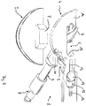
- FIGS. 8 and 9 Such a use in practice is in the FIGS. 8 and 9 shown from two different views. There is shown how this is done for the Forming a corresponding recess for anchoring an implant part for a knee replacement prosthesis provided tooling system 1 is used.
- the distal end of the femur Fe and the proximal end of the tibia Ti can be seen here.
- a plateau At the proximal end of the tibia Ti, a plateau has been previously created on one side by a horizontal section, on which the base part 4 of the tool system 1 is placed with its support section 14.
- the base part 4 is aligned according to the position of the recess to be introduced and (not shown here) fixed by introducing one or more retaining pins through one or more of the pin holes 16 into the bone in this position.
- the carriage 5 is applied and fixed to the base member 4 in the longitudinal slot for longitudinal guidance, and it is the milling tool 2 passed through the guide channel in the carriage 5 and by reciprocating the carriage 5 with up to the stop inserted milling tool 2 in the Cross-section trapezoidal recess precisely applied.
- the milling tool 2 with its axis safely protrudes from the area in which a particularly small gap is left between tibia Ti and femur Fe.
- the femur Fe does not have to be separated as far from the tibia Ti as usual, so that a soft-tissue-friendly operation is possible, in particular while preserving the natural ligaments, in particular the cruciate ligaments.
- the shield section 20 prevents the femur Fe or adjacent soft parts from being damaged inadvertently when working with the milling tool 2 because the shield section 20 securely shields the broaching end of the milling tool 2 with the milling cutters there.
Landscapes
- Health & Medical Sciences (AREA)
- Surgery (AREA)
- Life Sciences & Earth Sciences (AREA)
- Medical Informatics (AREA)
- Animal Behavior & Ethology (AREA)
- Veterinary Medicine (AREA)
- Oral & Maxillofacial Surgery (AREA)
- Engineering & Computer Science (AREA)
- Biomedical Technology (AREA)
- Heart & Thoracic Surgery (AREA)
- Public Health (AREA)
- Molecular Biology (AREA)
- Nuclear Medicine, Radiotherapy & Molecular Imaging (AREA)
- General Health & Medical Sciences (AREA)
- Dentistry (AREA)
- Orthopedic Medicine & Surgery (AREA)
- Pathology (AREA)
- Surgical Instruments (AREA)
- Prostheses (AREA)
- Dental Tools And Instruments Or Auxiliary Dental Instruments (AREA)
Description
Die vorliegende Erfindung betrifft ein medizinisches Werkzeugsystem zum Präparieren einer trapezförmigen Ausnehmung in einer Gelenkfläche eines Knochens mit den Merkmalen des Oberbegriffes des Anspruches 1.The present invention relates to a medical tool system for preparing a trapezoidal recess in a joint surface of a bone with the features of the preamble of
Es ist bereits seit langem üblich, auf dem Gebiet der chirurgischen Orthopädie verschlissene, sklerotische oder durch andere Erkrankungen beschädigte Gelenke ganz oder teilweise durch prothetische Implantate zu ersetzen. So gehören heutzutage insbesondere der Ersatz von Kniegelenken durch entsprechende Implantate wie auch das Setzen künstlicher Hüftgelenke oder Hüftgelenksteile zum Standardoperationsrepertoire der chirurgischen Orthopädie. Dabei haben sich in der Vergangenheit abhängig von der Schwere des Gelenkdefektes ganz unterschiedliche Techniken und Operationsmethoden herausgebildet. Neben Totalersatzprothesen, bei denen z.B. bei einem verschlissenen Kniegelenk sowohl im Bereich des Femurs als auch im Bereich der Tibia die Gelenkflächen und auch angrenzende Knochenabschnitt vollständig durch künstlich gebildete Implantatteile ersetzt werden, sind heutzutage auch Techniken und Konstellationen geläufig, bei denen unter weitest möglichem Erhalt der natürlichen Knochensubstanz nur partielle Ersetzungen von verschlissenen Gelenkflächen vorgenommen werden. So gibt es beispielsweise Implantatsysteme, bei denen in Kniegelenken teilprothetisch lediglich eine der beiden Kondylen der tibiaseitigen Gelenkfläche ersetzt, die andere Kondyle natürlich belassen wird und auch nur auf der der ersetzten, mit dem künstlichen Implantat versorgten Kondylenfläche gegenüberliegender Seite des Femurteils eine künstliche Lauffläche des Gelenkes aufgebracht wird.It has long been common in the field of surgical orthopedics to replace worn, sclerotic or other diseases damaged joints in whole or in part by prosthetic implants. For example, the replacement of knee joints with appropriate implants as well as the setting of artificial hip joints or hip joint parts are now standard surgical orthopedic surgical repertoire. In the past, quite different techniques and surgical methods have developed depending on the severity of the joint defect. In addition to total replacement prostheses in which e.g. In a worn knee joint both in the area of the femur and in the area of the tibia, the joint surfaces and adjacent bone portion are completely replaced by artificially formed implant parts, nowadays techniques and constellations are common in which, as far as possible preserving the natural bone substance only partial substitutions of worn joint surfaces are made. For example, there are implant systems in which only one of the two condyles of the tibial joint surface is partially replaced in knee joints, the other condyle is left natural and only on the replaced, supplied with the artificial implant condylar surface of the opposite side of the femur an artificial tread of the joint is applied.
Derartige Teilprothesen werden häufig mit leistenförmigen oder anders geformten Fortsätzen im Knochen verankert, z.B. mit sogenannten Finnen. Diese Finnen, die mit einem gewissen Übermaß in eine entsprechende im Knochenmaterial geschaffene Ausnehmung bzw. eine ausgeräumte Nut eingepresst werden, sind dabei häufig im Querschnitt trapezförmig gebildet. Derartige Befestigungsmechanismen können aber nicht nur bei Teilimplantaten verwendet werden, sondern auch für andere am Knochen festzulegende Implantate, auch für Totalersatzprothetik.Such partial dentures are often anchored with strip-shaped or differently shaped projections in the bone, for example with so-called fins. These Finns, with a certain excess in a corresponding in the Bone material created recess or an evacuated groove are pressed, are often trapezoidal in cross section formed. However, such attachment mechanisms can not only be used with partial implants, but also for other implants to be fixed to the bone, even for total replacement prosthetics.
Gerade aber dann, wenn schonende Teilersatzprothesen gesetzt werden, wird auch unter der Operation auf einen weitestgehenden Erhalt und eine beschädigungsfreie Belassung der den Gelenkbereich umgebenden Weichteile, insbesondere der Bänder, geachtet. Entsprechend wird eine Trennung des natürlichen Gelenkes so gering wie möglich gehalten, um hier die Belastungen zu reduzieren und den Regenerations- und Heilungsprozess zu befördern, die durch die natürlichen Weichteile gegebene Gelenkstabilität soweit als möglich zu erhalten. Deshalb müssen entsprechende Werkzeugsysteme, mit denen die Strukturen im beschädigten Knochen geschaffen werden müssen, in denen Prothesenteile festgelegt werden, so gebildet sein, dass sie auch in kleinen Spalträumen eingesetzt werden können, dabei jedoch ausreichend präzise wirken.But just when gentle part replacement prostheses are set, even under the operation on a largely preserved and damage-free preservation of the joint area surrounding soft tissue, especially the tapes, respected. Accordingly, a separation of the natural joint is kept as low as possible in order to reduce the burden and to promote the regeneration and healing process, as far as possible to maintain the joint stability given by the natural soft tissues. Therefore, appropriate tooling systems, with which the structures in the damaged bone must be created, in which prosthesis parts are set, must be formed so that they can be used in small fissures, but act sufficiently precise.
Während früher es vielfach dem Geschick und handwerklichem Vermögen des Operateurs überlassen wurde, die Gelenkflächen der beteiligten Knochen für den Ersatz verschlissener Gelenkbereiche frei Hand zu präparieren, finden inzwischen vermehrt werkzeugtechnische Hilfsmittel Eingang, um hier dem Operateur das Handwerk zu erleichtern und für eine sichere und präzise Anordnung und Ausbildung der erforderlichen Strukturen zu sorgen.While in the past it was often left to the skill and craft of the surgeon to freely prepare the articular surfaces of the involved bones for the replacement of worn joint areas, tooling aids are increasingly being used to facilitate the craftsman's trades and ensure their safety and accuracy Arrangement and training of the necessary structures.
So sind verschiedentlich Werkzeugsysteme zum Räumen von Knochenmaterial bekannt, bei denen Schablonen mit Fräsen zusammenwirken, um Ausnehmungen vorgegebener Form und Tiefe schaffen zu können.For example, tool systems for broaching bone material are known in which templates interact with milling to be able to create recesses of predetermined shape and depth.
Ein solches Werkzeugsystem, welches zum Fräsen von Ausnehmungen einer vorgegebenen Kontur verwendet wird, ist in der
In der
Zudem ist am Markt ein Implantatsystem für einen Teilersatz des Knies mit einer einseitig zu ersetzenden Kondylenfläche und einem ebenfalls einseitig am Femur anzubringenden Gelenkflächenimplantat bekannt, welches von dem US-Unternehmen Stryker Corporation unter der Marke EIUS™ vertrieben wird. Für dieses Implantatsystem ist ein Präparationswerkzeug vorgesehen, in welchem eine trapezförmige Ausnehmung in der zu versorgenden Kondylenfläche der Tibia ausgebildet wird. Hierzu ist ein Schablonenteil mit einem Plattenelement gegeben, welches einen fest mit dem Plattenelement verbundenen, einen rechteckigen Querschnitt aufweisenden Röhrenabschnitt aufweist, der einen Werkzeugtunnel bildet, der in etwa 45° geneigt zu der Ebene der Platte verläuft. Zum Ausbilden der trapezförmigen Ausnehmung wird in diesem Tunnel zunächst eine Bohrschablone eingesetzt, und es werden Schwächungsbohrungen in das Knochenmaterial eingebracht. Anschließend wird der Bohreinsatz entnommen und der so perforierte Knochen durch einen ebenfalls durch den Tunnel eingebrachten Räummeißel fertig geräumt zum Ausbilden der Ausnehmung, in die die Finne des Kondylenimplantates eingebracht wird. Das Werkzeugsystem ist einerseits vielteilig und das damit einhergehende Verfahren zur Ausbildung der Ausnehmung ist umständlich. Denn es müssen hier mit verschiedenen Werkzeugen zunächst die Bohrungen eingebracht und dann die endgültige Räumung der Ausnehmung vorgenommen werden. Diese Vorgehensweise kostet wertvolle Operationszeit und führt zudem dazu, dass im Anschluss der Operation eine Vielzahl von Teilen und Instrumenten zu reinigen und zu desinfizieren sind.In addition, an implant system for a partial replacement of the knee with a unilaterally replaced condylar surface and also to be attached on one side of the femur joint surface implant is known, which is sold by the US company Stryker Corporation under the brand EIUS ™. For this implant system, a preparation tool is provided, in which a trapezoidal recess is formed in the to be supplied Kondylenfläche the tibia. For this purpose, a template part is provided with a plate member having a fixedly connected to the plate member, having a rectangular cross-section tubular portion which forms a tool tunnel which extends at approximately 45 ° inclined to the plane of the plate. To form the trapezoidal recess, a drilling template is first used in this tunnel, and weakening holes are introduced into the bone material. Subsequently, the drill bit is removed and the thus perforated bone is finished by a clearing tool also inserted through the tunnel to form the recess into which the fin of the condylar implant is inserted. On the one hand, the tool system has many parts and the associated method of forming the recess is cumbersome. Because it must be here with various tools initially introduced the holes and then made the final clearance of the recess. This procedure costs valuable operating time and, moreover, means that a large number of parts and instruments must be cleaned and disinfected following the operation.
Das Dokument
Hier eine Vereinfachung zu geben und ein optimiertes medizinisches Werkzeugsystem zu schaffen, mit dem auch unter räumlich engen Verhältnissen einfach und zuverlässig trapezförmige Ausnehmungen in einer Gelenkfläche eines Knochens geschaffen werden können, ist Aufgabe der Erfindung. Insbesondere soll dieses Werkzeugsystem geeignet sein für das Anbringen einer solchen trapezförmigen Ausnehmung in einer Kondylenfläche des Tibiaanteils des Kniegelenkes, z.B. für die Vorbereitung zum Setzen einer Teilersatzprothese in diesem Bereich.To give a simplification here and to create an optimized medical tool system with which even under close spatial conditions can be created easily and reliably trapezoidal recesses in a joint surface of a bone, is the object of the invention. In particular, this tool system should be suitable for mounting such a trapezoidal recess in a condylar surface of the tibial component of the knee joint, e.g. for preparing to place a partial replacement prosthesis in this area.
Diese Aufgabe wird erfindungsgemäß gelöst durch ein medizinisches Werkzeugsystem mit den Merkmalen des Anspruches 1. Vorteilhafte Weiterbildungen dieses neuartigen Werkzeugsystems sind in den abhängigen Ansprüchen 2 bis 9 bezeichnet.This object is achieved by a medical tool system with the features of
Das neuartige medizinische Werkzeugsystem zum Präparieren einer trapezförmigen Ausnehmung in einer Gelenkfläche eines Knochens nach der Erfindung weist - und dies zunächst in Übereinstimmung mit bekannten vergleichbaren Werkzeugssystemen - ein um eine Werkzeugachse zur Rotation antreibbares Fräswerkzeug auf, welches umfangsseitig wirkende Frässchneiden und zudem Frässchneiden aufweist, die an einem bezogen auf die Werkzeugachse axialen Ende wirken. Es hat ferner - und auch dies in Übereinstimmung mit vorbekannten vergleichbaren Werkzeugsystemen - ein an der Gelenkfläche festlegbares Schablonenteil zum Führen des Fräswerkzeuges, und es ist ein eine Eindringtiefe des Fräswerkzeuges begrenzender Anschlag vorgesehen.The novel medical tool system for preparing a trapezoidal recess in a joint surface of a bone according to the invention has - and this first in accordance with known comparable tool systems - a drivable around a tool axis for rotation milling tool, which has circumferentially acting milling cutters and also milling cutters on one acting on the tool axis axial end. It also has - and also in accordance with prior art comparable tool systems - a fixable on the articular surface template part for guiding the milling tool, and it is provided a penetration depth of the milling tool limiting stop.
Das Besondere an dem erfindungsgemäßen Werkzeugsystem besteht nun darin, dass das Schablonenteil ein Basiselement mit einer Schlittenführung aufweist und weiterhin in der Schlittenführung zwischen zwei Endanschlägen entlang einer in einer Führungsebene liegenden Führungsbahn bewegbaren Schlitten. Ferner ist erfindungsgemäß in dem Schlitten ein Führungskanal zur Aufnahme des Fräswerkzeuges gebildet. In diesem Führungskanal ist das darin aufgenommene Fräswerkzeug dann quer zu der Werkzeugachse geführt, d.h. es kann sich nicht in einer Richtung quer zu dieser Werkzeugachse relativ zu dem Führungskanal bewegen. In dem Führungskanal kann das Fräswerkzeug sich allerdings frei um die Werkzeugachse drehen und in axialer Richtung bewegt werden.The special feature of the tool system according to the invention consists in the fact that the template part has a base element with a Carriage guide and further in the carriage guide between two end stops along a guide track lying in a guide track movable carriage. Further, according to the invention, a guide channel for receiving the milling tool is formed in the carriage. In this guide channel, the milling tool received therein is then guided transversely to the tool axis, ie it can not move in a direction transverse to this tool axis relative to the guide channel. In the guide channel, however, the milling tool can rotate freely about the tool axis and be moved in the axial direction.
Das erfindungsgemäße Werkzeugsystem kann z.B. zum Ausbilden einer trapezförmigen Ausnehmung an einer Kondylenfläche des Tibiateils eines Kniegelenkes eingesetzt werden, ist hierfür besonders geeignet. Bei der Präparation der Kondylenfläche zum Setzen eines prothetischen Implantates wird diese zunächst in einem quer zur Längsachse der Tibia geführten Schnitt und einem quer zu diesem Schnitt geführten Trennschnitt derart präpariert, dass dort ein ebenes Plateau entsteht. In dieses ebene Plateau wird dann eine trapezförmige Ausnehmung eingebracht, in die ein Verankerungsfortsatz, typischerweise als Finne bezeichnet, eines entsprechenden Implantates eingepresst werden kann. Hierzu wird nach Präparation des ebenen Plateaus auf die dann entstandene Fläche das Basiselement des Schablonenteils des erfindungsgemäßen Werkzeugsystems aufgesetzt und insbesondere fixiert. Der auf dem Basiselement in der Schlittenführung zwischen den beiden Endanschlägen hin und her bewegbare Schlitten kann nun zwischen diesen Endabschlägen hin und her gleiten, entsprechender Raum steht auch bei minimalinvasiven Operationstechniken zur Verfügung. Durch den Führungskanal in dem Schlitten wird das Fräswerkzeug eingebracht und in Rotation versetzt. Dabei schneidet das Fräswerkzeug in die Knochenoberfläche, dies unter dem voreingestellten Winkel der Schrägstellung des Führungskanals relativ zu der Führungsebene. Durch Hin- und Herbewegen des Schlittens, Vor- und Zurückbewegen des Fräswerkzeuges in dem Führungskanal bis maximal zu dem Anschlag bei gleichzeitiger Rotation des Fräswerkzeuges wird eine entsprechende Ausnehmung frei geräumt. Der Anschlag verhindert, dass das Fräswerkzeug zu tief in den Knochen eindringt und bestimmt die Tiefe der Ausnehmung. Dadurch, dass das Fräswerkzeug sowohl in Umfangsrichtung als auch in Richtung des axialen Endes wirkende Frässchneiden aufweist, räumt es die Ausnehmung an einer durch das axiale Endes des Fräsers gebildeten Flanke, die entsteht, wenn der Schlitten maximal in einer Vorschubrichtung des Fräswerkzeuges in der Schlittenführung bis zum Endanschlag bewegt ist und das Fräswerkzeug bis zum Anschlag in den Führungskanal eingebracht ist, glatt und sauber aus. Die Schrägstellung des Führungskanals auf dem Schlitten ist dabei insbesondere so, dass ein von der Führungsebene wegzeigender Anteil an einem vorderen, d.h. während der Operation proximal anzusetzenden Ende des Schlittens gelegen ist. Hierdurch entsteht eine Art Keilform des Führungskanals auf dem Schlitten, mit der geringeren Höhe in Richtung des distalen Endes des natürlichen Kniegelenkes, so dass dort die benötigte Arbeitshöhe am geringsten ist, die während der Operation typischerweise dorthin verlagerten weiteren Teile des Kniegelenkes, nämlich der Femur mit den Weichteilen, insbesondere den Bändern, den Vorgang nicht stören, entsprechend substanzerhaltend gearbeitet werden kann.The tool system according to the invention can be used, for example, to form a trapezoidal recess on a condylar surface of the tibial part of a knee joint, which is particularly suitable for this purpose. During the preparation of the condylar surface for setting a prosthetic implant, it is first prepared in a cross-section taken transversely to the longitudinal axis of the tibia and a cross-section cut across this section in such a way that a flat plateau is formed there. In this plane plateau then a trapezoidal recess is introduced into which an anchoring process, typically referred to as a fin, a corresponding implant can be pressed. For this purpose, the base element of the template part of the tool system according to the invention is placed and in particular fixed after preparation of the flat plateau on the then resulting surface. The carriage, which can be moved back and forth on the base element in the slide guide between the two end stops, can now glide back and forth between these end stops, corresponding space is also available in minimally invasive surgical techniques. Through the guide channel in the carriage, the milling tool is introduced and set in rotation. In this case, the milling tool cuts into the bone surface, this at the preset angle of inclination of the guide channel relative to the guide plane. By moving the carriage back and forth, moving the milling tool back and forth in the guide channel to a maximum to the stop with simultaneous rotation of the milling tool a corresponding recess is cleared. The stop prevents the milling tool from penetrating too deeply into the bone and determines the depth of the recess. Characterized in that the milling tool has both in the circumferential direction and in the direction of the axial end acting milling cutters, it admits the recess at a formed by the axial end of the cutter flank, which is formed when the carriage maximum in a feed direction of the milling tool in the carriage guide moved to the end stop and the milling tool is inserted all the way into the guide channel, smooth and clean. The inclination of the guide channel on the carriage is in particular such that a pointing away from the management level portion of a front, that is located proximal to be applied during surgery end of the carriage is located. This results in a kind of wedge shape of the guide channel on the carriage, with the lower height in the direction of the distal end of the natural knee joint, so that there is the required working height is the lowest, during the operation typically shifted there further parts of the knee joint, namely the femur with the soft tissues, in particular the bands, do not interfere with the process, can be worked accordingly substance preserving.
Anders als z.B. bei dem bekannten System des Anbieters Stryker Corporation wird hier mit einem einzigen Werkzeug, nämlich dem Fräswerkzeug, die vollständige Ausräumung der Ausnehmung bewerkstelligt, und es muss nicht eine Vorarbeit mit Knochenbohrern und ein anschließendes Fertigausräumen mit einem Meißelwerkzeug erfolgen.Unlike e.g. in the known system of the supplier Stryker Corporation here with a single tool, namely the milling tool, the complete clearing of the recess accomplished, and there is no preliminary work with bone drills and subsequent Fertigausräumen done with a chisel tool.
Mit Vorteil ist, wie gemäß einer Weiterbildung der Erfindung vorgesehen, das Basiselement plattenförmig und eben gebildet. Mit der plattenförmigen und ebenen Gestaltung passt sich das Basiselement besonders gut der typischerweise eben vorbereiteten Fläche nach dem Kondylenschnitt an. Darüber hinaus ist mit einem plattenförmigen Basiselement eine besonders geringe Bauhöhe zu erzielen, was im Hinblick auf die oben bereits geschilderten Ziele eines minimalen Eingriffes in die natürliche Gelenkstruktur von Vorteil ist. Die Stärke des plattenförmigen Basiselementes wird dabei in der Regel derart gewählt werden, dass eine ausreichend stabile und genaue Führung des Schlittens möglich ist, zugleich eine möglichst geringe Stärke eingestellt wird.Advantageously, as provided according to a development of the invention, the base element plate-shaped and flat. With the plate-shaped and planar design, the base element adapts particularly well to the surface that has just been prepared, after the condyle cut. In addition, with a plate-shaped base element to achieve a particularly low height, which in view of the above-mentioned objectives of a minimum intervention in the natural Joint structure is beneficial. The thickness of the plate-shaped base element will usually be chosen such that a sufficiently stable and accurate guidance of the carriage is possible, at the same time the lowest possible strength is set.
Mit Vorteil kann bei dem erfindungsgemäßen Werkzeugsystem die Schlittenführung in dem Basiselement durch einen gerade verlaufenden Längsschlitz gebildet sein, in dem ein Führungsfortsatz des Führungsschlittens aufgenommen ist. Eine solche Schlittenführung ist einerseits technisch einfach zu realisieren und leicht zu bedienen, andererseits ist sie die ideale Führung für das Bilden einer gerade verlaufenden, im Querschnitt trapezförmigen Ausnehmung. Die Trapezform der Ausnehmung entsteht dabei aufgrund der zu einem Untergrund der Ausnehmung und auch zu der nach dem Kondylenschnitt verbleibenden ebenen Oberfläche schräggestellten Stellung der Achse des Fräswerkzeuges. Eine vordere Begrenzungsfläche ist dieser Achsstellung folgend schräg, eine hintere Begrenzungsfläche wird aufgrund der an dem axialen Ende wirkenden Frässchneiden schräg gebildet, dies insbesondere dann, wenn die an dem bezogen auf die Werkzeugachse axialen Ende wirkenden Frässchneiden bei der Fräsbearbeitung eine Fläche fräsen, die im Wesentlichen plan und senkrecht zu der Rotationsachse ist. Der Fräser kann in einem einfachsten Fall eine zylinderförmige Außenkontur aufweisen mit einem freien axialen Ende, welches im Wesentlichen senkrecht zu der Werkzeugachse verläuft und mit Fräskanten bzw. -schneiden entlang des Umfanges und an dem vorderen Ende.Advantageously, in the tool system according to the invention, the carriage guide can be formed in the base element by a straight longitudinal slot in which a guide extension of the guide carriage is received. On the one hand, such a slide guide is technically simple to realize and easy to operate; on the other hand, it is the ideal guide for the formation of a straight, trapezoidal-shaped recess. The trapezoidal shape of the recess arises due to the position of the axis of the milling tool which is inclined to a substrate of the recess and also to the flat surface remaining after the condyle section. A front boundary surface is obliquely following this axial position, a rear boundary surface is obliquely formed due to the milling cutters acting on the axial end, in particular when the milling cutters acting on the axial end relative to the tool axis mill a surface substantially during milling plan and perpendicular to the axis of rotation. In a simplest case, the milling cutter can have a cylindrical outer contour with a free axial end which runs substantially perpendicular to the tool axis and with milling edges along the circumference and at the front end.
Der Führungskanal ist mit Vorteil gegenüber der Führungsebene um einen Winkel von 30° bis 60° geneigt, insbesondere in einem Winkel von 40° bis 50°, wobei eine Neigung um einen Winkel von 45° besonders bevorzugt ist. Die genannten Winkelbereiche ergeben solche Schrägstellungen des Fräswerkzeuges, die auch unter Berücksichtigung der langen mit einem Fräsantrieb zu verbindenden Fräswelle nicht mehr störend und raumgreifend in den eigentlichen Gelenkbereich eingreifen, d.h. den Bereich, in dem sich der für die Operation beiseite gelegte Partnerknochen des die zu bearbeitende Gelenkfläche aufweisenden Knochens befindet sowie die Weichteile des Gelenkes liegen. Hierin unterscheidet sich die erfindungsgemäße Lösung deutlich von der
Insbesondere bevorzugt wird hier ein Winkel von 45°, da mit diesem eine trapezförmige Ausnehmung geschaffen wird, deren seitliche, schräg verlaufende Begrenzungsflächen beide unter einem Winkel von 45° verlaufen. Die erste folgt der Neigung der Werkzeugachse gegenüber der Führungsebene; die zweite Seitenfläche ist entsprechend um 90° verkippt geneigt, also um 45° gegenüber der Führungsfläche in der anderen Ausrichtung. Dieser Unterschied von 90° ist bedingt durch die Ausgestaltung des Fräswerkzeuges, welches an seinem axialen Ende eine vertikal zur Werkzeugachse verlaufenden Flächenabschnitt herausarbeitenden so wirkenden Frässchneiden.Particularly preferred here is an angle of 45 °, since with this a trapezoidal recess is created, the lateral, obliquely extending boundary surfaces both extend at an angle of 45 °. The first follows the inclination of the tool axis with respect to the guide plane; the second side surface is tilted accordingly tilted by 90 °, ie by 45 ° relative to the guide surface in the other orientation. This difference of 90 ° is due to the design of the milling tool, which at its axial end a vertically extending to the tool axis surface portion ausarbeitenden thus acting milling cutters.
Gemäß einer weiteren vorteilhaften Weiterbildung der Erfindung kann der Führungskanal in einem rohrförmigen Abschnitt des Schlittens angeordnet sein, der einen oberen Rand aufweist. Das Fräswerkzeug weist bei dieser Weiterbildung einen quer zu der Rotationsachse überstehenden Kragen auf. Der Rand des rohrförmigen Abschnittes und der Kragen bilden dabei zusammen den Anschlag, über den die Eindringtiefe des Fräswerkzeuges in den Führungskanal und damit die Arbeitstiefe im Knochenmaterial beschränkt wird, um so die Tiefe der trapezförmigen Ausnehmung zu bestimmen und exakt einzuhalten.According to a further advantageous embodiment of the invention, the guide channel may be arranged in a tubular portion of the carriage having an upper edge. The milling tool has in this development on a transverse to the axis of rotation protruding collar. The edge of the tubular portion and the collar together form the stop, via which the penetration depth of the milling tool is limited in the guide channel and thus the working depth in the bone material, so as to determine the depth of the trapezoidal recess and comply exactly.
Für eine einfachere Reinigung und Sterilisation des Schablonenteils können mit Vorteil Schlitten- und Basiselement lösbar miteinander verbunden sein. Dies verhindert insbesondere das Erfordernis der Reinigung bzw. Sterilisation von ansonsten ggf. bestehenden Spalten im Bereich der beweglichen Verbindung.For easier cleaning and sterilization of the template part, slide and base elements can advantageously be detachably connected to one another. This prevents in particular the need for cleaning or sterilization of otherwise possibly existing gaps in the region of the movable connection.
Um das Schablonenteil an dem zu bearbeitenden Knochen festzulegen und damit die Lage der mit Hilfe des Schablonenteils und dem mit diesem zusammenwirkenden Fräswerkzeug in den Knochen einzubringenden Ausnehmung einzuhalten, kann das Basiselement des Schablonenteils mit Vorteil Pinlöcher aufweisen. Solche Pinlöcher sind Durchtrittsöffnungen, durch die Befestigungsstifte oder Schrauben, sogenannte Steckpins oder Schraubpins in zuvor in den Knochen eingebrachte Bohrlöcher eingesetzt werden können. Derartige Pins sind hinlänglich bekannt und werden in großem Umfang in der orthopädischen Chirurgie zum Festlegen von Hilfsvorrichtungen und Werkzeugführungen eingesetzt.To fix the template part of the bone to be processed and thus to comply with the position of the insert by means of the template part and the cooperating with this milling tool into the bone recess, the base element of the template part with Advantage have pinholes. Such pin holes are passage openings through which fastening pins or screws, so-called plug pins or screw pins in previously introduced into the bone holes can be used. Such pins are well known and widely used in orthopedic surgery for securing auxiliary devices and tool guides.
Für ein einfaches Positionieren beim korrekten Setzen des Schablonenteils kann an dem Basiselement ein Handgriffabschnitt ausgebildet sein.For easy positioning when correctly setting the template part, a handle section can be formed on the base element.
Aus der vorstehenden Beschreibung wird deutlich, dass mit dem erfindungsgemäßen Werkzeugsystem auf einfache Weise sehr präzise und schnell eine trapezförmige Ausnehmung in eine Gelenkfläche eines Knochen eingebracht werden kann, ohne dass es hierzu des Einsatzes verschiedenster Werkzeuge etwa bedarf. Dies kann aufgrund der Schrägstellung des Führungskanals relativ zu der Führungsebene auch unter räumlich beengten Verhältnissen unternommen werden, wie sie insbesondere dann vorherrschen, wenn die Operation weitgehend substanzerhaltend erfolgen soll, insbesondere unter Erhalt der Weichteile des Gelenkes, z.B. der Kreuzbänder eines zu versorgenden Kniegelenkes.From the above description it is clear that with the tool system according to the invention in a simple manner can be very precisely and quickly introduced a trapezoidal recess in a joint surface of a bone, without requiring the use of various tools for this purpose. This can be done due to the inclination of the guide channel relative to the management level even in cramped conditions, as prevail especially when the operation is to be largely substance-preserving, in particular while preserving the soft tissues of the joint, e.g. the cruciate ligaments of a knee joint to be supplied.
Weitere Vorteile und Merkmale der Erfindung ergeben sich aus der nachfolgenden Beschreibung eines Ausführungsbeispiels anhand der beigefügten Figuren. Dabei zeigen:
-
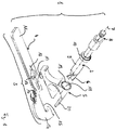
Fig. 1 in einer dreidimensionalen Explosionsdarstellung ein erfindungsgemäßes medizinisches Werkzeugsystem zum Präparieren einer im Querschnitt trapezförmigen Ausnehmung in einer Gelenkfläche eines Knochens in einem Ausführungsbeispiel; -
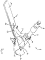
Fig. 2 das medizinische Werkzeugsystem ausFig. 1 in zusammengefügtem Zustand; -
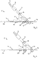
Fig. 3 das Werkzeugsystem ausFig. 2 in einer Seitenansicht mit in einer hinteren Endstellung befindlichem Schlitten; -
Fig. 4 in einer derFig. 3 vergleichbaren Ansicht das Werkzeugsystem ausFig. 1 mit in einer vorderen Endstellung befindlichem Schlitten; -
Fig. 5 in einer Ansicht von unten das medizinische Werkzeugsystem ausFig. 1 und im Vergleich dazu die Unterseite eines medizinischen Implantatteils mit einer im Querschnitt trapezförmigen Verankerungsfinne; -
Fig. 6 in einer übereinander gelegten Vergleichsdarstellung an der Seite das medizinische Werkzeugsystem ausFig. 1 und dahinter die im Querschnitt trapezförmige Finne eines Implantatteils, wobei in dieser Figur der Schlitten in seiner hinteren Anschlagstellung befindlich ist; -
Fig. 7 in einer Darstellung vergleichbar derFig. 6 das medizinische Werkzeugsystem mit dem Schlitten in einer vorderen Anschlagstellung und in Überlagerung wiederum mit der Ansicht der Finne; -
Fig. 8 in einer perspektivischen Darstellung das medizinische Werkzeugsystem im Einsatz zum Präparieren einer im Querschnitt trapezförmigen Ausnehmung auf einem zuvor herauspräparierten Tibiaplateau eines Kniegelenkes; -
Fig. 9 die inFig. 8 gezeigte Situation und Anordnung aus einem anderen Blickwinkel, hier in einer Seitenansicht.
-
Fig. 1 in a three-dimensional exploded view of an inventive medical tool system for preparing a trapezoidal cross-section recess in a joint surface of a bone in one embodiment; -
Fig. 2 the medical tool systemFig. 1 in assembled condition; -
Fig. 3 the tool systemFig. 2 in a side view with located in a rear end position slide; -
Fig. 4 in one of theFig. 3 comparable view of the tool systemFig. 1 with carriage located in a front end position; -
Fig. 5 in a view from below the medical tool systemFig. 1 and in comparison, the underside of a medical implant part with a trapezoidal anchoring fin in cross-section; -
Fig. 6 in a superimposed comparison representation on the side of the medical tool systemFig. 1 and behind it the cross-sectionally trapezoidal fin of an implant part, in this figure the carriage being in its rear stop position; -
Fig. 7 in a representation comparable toFig. 6 the medical tool system with the carriage in a front stop position and in overlay again with the view of the fin; -
Fig. 8 in a perspective view of the medical tool system in use for preparing a trapezoidal cross-section recess on a previously prepared tibial plateau of a knee joint; -
Fig. 9 in theFig. 8 shown situation and arrangement from a different angle, here in a side view.
In den Figuren ist ein mögliches Ausführungsbeispiel eines erfindungsgemäßen Werkzeugsystems gezeigt und wird nachfolgend anhand dieser Figuren näher beschrieben.In the figures, a possible embodiment of a tool system according to the invention is shown and will be described below with reference to these figures.
Das erfindungsgemäße Werkzeugsystem ist in den Figuren allgemein mit 1 bezeichnet und umfasst ein rotatorisch antreibbares Fräswerkzeug 2 sowie ein Schablonenteil 3. Das Schablonenteil 3 seinerseits ist zweiteilig gebildet mit einem Basiselement 4 und einem an dem Basiselement 4 festlegbaren, in einer Verfahrrichtung zwischen zwei Anschlagpunkten verfahrbaren Schlitten 5.The tool system according to the invention is generally designated 1 in the figures and comprises a rotary
Das Fräswerkzeug 2 ist in einer axialen Richtung erstreckt gebildet und weist an einem Räumende Frässchneiden 6 auf, die einerseits umfangsseitig wirken, andererseits auch an ihrem vordersten Ende eine Flächenräumwirkung entfalten entlang einer Räumfläche, die im Wesentlichen senkrecht steht zu der Längsachse 7 des Fräswerkzeuges 2. An seinem dem Räumende mit den Frässchneiden 6 gegenüberliegenden Ende weist das Fräswerkzeug 2 einen Kupplungsanschluss 8 auf zur Verbindung mit einem Rotationsantrieb. Ausgehend von dem mit Frässchneiden 6 besetzten Räumende in Richtung des Endes mit dem Kupplungsanschluss 8 erstreckt sich ein Zylinderabschnitt 9 bis hin zu einer ringförmig umlaufenden Verdickung 10, welche in ihrem Durchmesser größer ist als der Durchmesser des Zylinderabschnittes 9.The
Das Schablonenteil 3 ist, wie bereits ausgeführt, zweitteilig aufgebaut und besteht aus einem Basiselement 4 und einem an diesem Basiselement 4 lösbar festlegbaren, in festgelegtem Zustand in einer Schlittenführung geführten Schlitten 5. Das Basiselement 4 ist plattenförmig gebildet mit einem Griffabschnitt 11, an welchem dieses im Gebrauch ergriffen und gehalten werden kann. Es weist ferner einen Längsschlitz 12 auf, der durch eine Kreisbohrung 13 mit gegenüber der Schlitzbreite erweiterten Durchmesser an einer Position geöffnet ist. In einem in etwa halbkreisförmig gebildeten Auflageabschnitt 14 ist eine Werkzeugdurchtrittsausnehmung 15 gebildet. Ferner sind an dem Basiselement 4 insgesamt vier Pinlöcher 16 angeordnet.The
Der Schlitten 5 weist auf seiner Unterseite einen Führungspin auf, der mit einem kreisförmigen Rückhalteteller 17 endet. Der Durchmesser dieses kreisförmigen Rückhaltetellers 17 ist in etwa dem Durchmesser der Kreisbohrung 13 entsprechend, so dass der Rückhalteteller 17 durch die Kreisbohrung 13 geführt werden kann, um den Führungspin des Schlittens in den Längsschlitz 12 zur Längsführung des Schlittens 5 einzubringen und dort in allen Positionen mit Ausnahme derjenigen Position, in der der Rückhalteteller 17 und die Kreisbohrung 13 exakt fluchten, zu verriegeln.The
An dem Schlitten 5 ist ein Führungskanal 18 ausgebildet, der durch eine einen umlaufenden Rand 19 aufweisende Führungsöffnung und einen sich daran anschließenden, eine umlaufende zylinderförmige Wand aufweisenden Kanal gebildet ist. Der Durchmesser des Führungskanals 18 entspricht im Wesentlichen dem Durchmesser des Zylinderabschnittes 9, so dass das Fräswerkzeug 2 mit seinem mit Frässchneiden 6 bestückten Räumende voran in den Führungskanal 18 eingesetzt und darin seitlich sicher geführt rotieren kann. Dabei ist der Führungskanal 18 derart ausgerichtet, dass er schräg zu einer durch den Längsverlauf des Längsschlitzes 12 gebildeten Schlittenführungsachse liegt, insbesondere um einen Winkel von etwa 45°. An einer dem Griffabschnitt 11 abgewandten Vorderseite des Schlittens 5 ist in Verlängerung des Führungskanals 18 ein Schildabschnitt 20 angeordnet, der dazu dient, im Gebrauch des Werkzeugsystems 1 die Frässchneiden 6 in diesem Bereich abzudecken und insbesondere beim Einführen des Fräswerkzeuges 2 mit seinem Räumende voran in den Führungskanal 18 eine nicht gewollte Verletzung von zu erhaltendem umliegenden Gewebe oder Knochenabschnitten zu verhindern.On the
In
In
In
In
Hier veranschaulichen die
Ein solcher Einsatz in der Praxis ist in den
Das gezeigte Ausführungsbeispiel ist nicht beschränkend zu verstehen, sondern zeigt lediglich eine von mannigfaltig möglichen Verwirklichungen des erfindungsgemäßen medizinischen Werkzeugsystems.The illustrated embodiment is not meant to be limiting, but merely shows one of many possible realizations of the medical tool system according to the invention.
- 11
- Medizinisches WerkzeugsystemMedical tool system
- 22
- Fräswerkzeugmilling tool
- 33
- Schablonenteiltemplate part
- 44
- Basiselementbase element
- 55
- Schlittencarriage
- 66
- Frässchneidenmilling blades
- 77
- Längsachselongitudinal axis
- 88th
- Kupplungsanschlusscoupling connection
- 99
- Zylinderabschnittcylinder section
- 1010
- ringförmige Verdickungannular thickening
- 1111
- Griffabschnitthandle portion
- 1212
- Längsschlitzlongitudinal slot
- 1313
- Kreisbohrungcircular bore
- 1414
- AuflagabschnittAuflagabschnitt
- 1515
- WerkzeugdurchtrittsausnehmungWerkzeugdurchtrittsausnehmung
- 1616
- Pinlochin hole
- 1717
- RückhaltetellerRetaining plate
- 1818
- Führungskanalguide channel
- 1919
- umlaufender Randsurrounding border
- 2020
- Schildabschnittshield portion
- αα
- Winkelangle
- FF
- Finnefin
- FeFe
- Femurfemur
- II
- Implantatteilimplant part
- TiTi
- Tibiatibia
Claims (9)
- Medical tool system for preparing a trapezoidal recess in a joint surface of a bone (Ti), with a milling tool (2) which is driveable for rotation about a tool axis (7) and has milling cutters (6) acting at the circumference and milling cutters (6) acting at an axial end relative to the tool axis (7), and with a template part (3) which can be secured on the joint surface and serves to guide the milling tool (2), wherein a stop (10, 19) is provided that limits a depth of penetration of the milling tool (2), wherein the template part (3) has a base element (4) with a carriage guide (12), and a carriage (5) which is movable in the carriage guide (12) between two end stops along a guide path lying in a guide plane, wherein a guide channel (18) is formed in the carriage (5) and receives the milling tool (2), guided transversely with respect to the tool axis (7), in such a way that the milling tool (2) can rotate freely about the tool axis (7), characterized in that the guide channel (18) extends obliquely with respect to the guide plane and is inclined by an angle of 30° to 60° with respect to the guide plane.
- Tool system according to Claim 1, characterized in that the base element (4) is plate-shaped and flat.
- Tool system according to either of the preceding claims, characterized in that the carriage guide (12) is formed in the base element (4) by a rectilinear longitudinal slit, in which a guide extension of the guide carriage (5) is received.
- Tool system according to one of the preceding claims, characterized in that the guide channel (18) is inclined with respect to the guide plane by an angle of 40° to 50°, in particular by an angle of 45°.
- Tool system according to one of the preceding claims, characterized in that, during the milling operation, the milling cutters (6) acting at the axial end relative to the tool axis (7) mill out a surface which is substantially flat and perpendicular to the tool axis (7).
- Tool system according to one of the preceding claims, characterized in that the guide channel (18) is arranged in a tubular portion of the carriage (5) having upper edge (19), and in that the milling tool (2) has a collar (10) which protrudes transversely with respect to the tool axis, wherein the edge (19) and the collar (10) together form the stop (10, 19).
- Tool system according to one of the preceding claims, characterized in that the carriage (5) and base element (4) of the template part (3) are connected to each other releasably.
- Tool system according to one of the preceding claims, characterized by pinholes (16) in the base element (4).
- Tool system according to one of the preceding claims, characterized by a handle portion (11) on the base element (4).
Priority Applications (1)
| Application Number | Priority Date | Filing Date | Title |
|---|---|---|---|
| EP14701011.0A EP2964112B1 (en) | 2013-03-05 | 2014-01-16 | Medical tool system |
Applications Claiming Priority (3)
| Application Number | Priority Date | Filing Date | Title |
|---|---|---|---|
| EP13157855.1A EP2774555A1 (en) | 2013-03-05 | 2013-03-05 | Medical tool system |
| EP14701011.0A EP2964112B1 (en) | 2013-03-05 | 2014-01-16 | Medical tool system |
| PCT/EP2014/050797 WO2014135293A1 (en) | 2013-03-05 | 2014-01-16 | Medical tool system |
Publications (2)
| Publication Number | Publication Date |
|---|---|
| EP2964112A1 EP2964112A1 (en) | 2016-01-13 |
| EP2964112B1 true EP2964112B1 (en) | 2017-03-22 |
Family
ID=47790096
Family Applications (2)
| Application Number | Title | Priority Date | Filing Date |
|---|---|---|---|
| EP13157855.1A Withdrawn EP2774555A1 (en) | 2013-03-05 | 2013-03-05 | Medical tool system |
| EP14701011.0A Active EP2964112B1 (en) | 2013-03-05 | 2014-01-16 | Medical tool system |
Family Applications Before (1)
| Application Number | Title | Priority Date | Filing Date |
|---|---|---|---|
| EP13157855.1A Withdrawn EP2774555A1 (en) | 2013-03-05 | 2013-03-05 | Medical tool system |
Country Status (14)
| Country | Link |
|---|---|
| US (1) | US10194925B2 (en) |
| EP (2) | EP2774555A1 (en) |
| JP (1) | JP6263204B2 (en) |
| KR (1) | KR101764518B1 (en) |
| CN (1) | CN105007839B (en) |
| AR (1) | AR094980A1 (en) |
| AU (1) | AU2014224939B2 (en) |
| BR (1) | BR112015018813A2 (en) |
| CA (1) | CA2904423C (en) |
| ES (1) | ES2624418T3 (en) |
| IL (1) | IL241083B (en) |
| MX (1) | MX361634B (en) |
| RU (1) | RU2618922C2 (en) |
| WO (1) | WO2014135293A1 (en) |
Families Citing this family (7)
| Publication number | Priority date | Publication date | Assignee | Title |
|---|---|---|---|---|
| EP2651341B1 (en) | 2010-12-16 | 2017-01-04 | Engage Medical Holdings, LLC | Arthroplasty systems and methods |
| US20180078264A1 (en) | 2014-03-03 | 2018-03-22 | Biomet Uk Healthcare Limited | Rotary mill |
| GB2518891B (en) | 2013-10-07 | 2020-03-18 | Biomet Uk Healthcare Ltd | Rotary mill |
| CN105411635B (en) * | 2015-12-22 | 2017-12-15 | 雷俊虎 | Anterior cruciate ligament of knee joint femoral bone tunnel goes out pin direction guided positioning system |
| US10456272B2 (en) | 2017-03-03 | 2019-10-29 | Engage Uni Llc | Unicompartmental knee arthroplasty |
| US11540928B2 (en) | 2017-03-03 | 2023-01-03 | Engage Uni Llc | Unicompartmental knee arthroplasty |
| CN111340876A (en) * | 2020-02-21 | 2020-06-26 | 京东方科技集团股份有限公司 | Treatment method, apparatus, storage medium and electronic device for knee replacement |
Family Cites Families (17)
| Publication number | Priority date | Publication date | Assignee | Title |
|---|---|---|---|---|
| SU858791A1 (en) * | 1979-11-01 | 1981-08-30 | Ленинградский научно-исследовательский детский ортопедический институт им. Г.И.Турнера | Method and apparatus for hip-joint displasia therapy |
| DE19501550A1 (en) | 1995-01-19 | 1996-07-25 | Dieter Prof Dr Med Wessinghage | Bone preparing device for prosthetic implants |
| US5810829A (en) * | 1996-02-21 | 1998-09-22 | Smith & Nephew, Inc. | Posterior stabilized/constrained reamer guide |
| US5653714A (en) * | 1996-02-22 | 1997-08-05 | Zimmer, Inc. | Dual slide cutting guide |
| US7163541B2 (en) | 2002-12-03 | 2007-01-16 | Arthrosurface Incorporated | Tibial resurfacing system |
| AU2003253602A1 (en) * | 2002-05-09 | 2003-11-11 | Hayes Medical, Inc. | Bone milling instrument |
| US20030236522A1 (en) | 2002-06-21 | 2003-12-25 | Jack Long | Prosthesis cavity cutting guide, cutting tool and method |
| US6994730B2 (en) | 2003-01-31 | 2006-02-07 | Howmedica Osteonics Corp. | Meniscal and tibial implants |
| DE20303643U1 (en) * | 2003-02-28 | 2003-07-10 | Aesculap AG & Co. KG, 78532 Tuttlingen | Surgical positioning and holding device, comprising pivoted tool guiding device for precise preparation of particular bone area |
| US7766913B2 (en) * | 2004-12-07 | 2010-08-03 | Depuy Products, Inc. | Bone shaping instrument and method for using the same |
| US20060189989A1 (en) * | 2005-02-10 | 2006-08-24 | Bert Jeffrey K | Zero profile template for installation of surgical plate |
| US7695477B2 (en) * | 2005-05-26 | 2010-04-13 | Zimmer, Inc. | Milling system and methods for resecting a joint articulation surface |
| GB0606837D0 (en) * | 2006-04-05 | 2006-05-17 | Depuy Int Ltd | Cutting guide instrument |
| WO2008030842A2 (en) * | 2006-09-06 | 2008-03-13 | Smith & Nephew, Inc. | Implants with transition surfaces and related processes |
| US20080183172A1 (en) * | 2007-01-26 | 2008-07-31 | Zimmer Technology, Inc. | Retention feature for plate guides |
| JP5882340B2 (en) * | 2010-10-07 | 2016-03-09 | ビーダーマン・テクノロジーズ・ゲゼルシャフト・ミット・ベシュレンクテル・ハフツング・ウント・コンパニー・コマンディートゲゼルシャフトBiedermann Technologies Gmbh & Co. Kg | Osteosynthesis plate assembly with guide members |
| EP2514372A1 (en) * | 2011-04-21 | 2012-10-24 | Deru GmbH | Set of instruments for inserting a joint prosthetic, in particular knee prosthetic |
-
2013
- 2013-03-05 EP EP13157855.1A patent/EP2774555A1/en not_active Withdrawn
-
2014
- 2014-01-16 KR KR1020157022807A patent/KR101764518B1/en not_active Expired - Fee Related
- 2014-01-16 BR BR112015018813A patent/BR112015018813A2/en active Search and Examination
- 2014-01-16 EP EP14701011.0A patent/EP2964112B1/en active Active
- 2014-01-16 AU AU2014224939A patent/AU2014224939B2/en not_active Ceased
- 2014-01-16 CA CA2904423A patent/CA2904423C/en not_active Expired - Fee Related
- 2014-01-16 ES ES14701011.0T patent/ES2624418T3/en active Active
- 2014-01-16 RU RU2015133526A patent/RU2618922C2/en not_active IP Right Cessation
- 2014-01-16 MX MX2015011681A patent/MX361634B/en active IP Right Grant
- 2014-01-16 US US14/771,083 patent/US10194925B2/en active Active
- 2014-01-16 CN CN201480008422.1A patent/CN105007839B/en not_active Expired - Fee Related
- 2014-01-16 WO PCT/EP2014/050797 patent/WO2014135293A1/en not_active Ceased
- 2014-01-16 JP JP2015560590A patent/JP6263204B2/en not_active Expired - Fee Related
- 2014-03-05 AR ARP140100695A patent/AR094980A1/en active IP Right Grant
-
2015
- 2015-09-02 IL IL241083A patent/IL241083B/en active IP Right Grant
Non-Patent Citations (1)
| Title |
|---|
| None * |
Also Published As
| Publication number | Publication date |
|---|---|
| RU2015133526A (en) | 2017-04-07 |
| JP6263204B2 (en) | 2018-01-17 |
| US20160008012A1 (en) | 2016-01-14 |
| CA2904423A1 (en) | 2014-09-12 |
| WO2014135293A1 (en) | 2014-09-12 |
| JP2016508801A (en) | 2016-03-24 |
| RU2618922C2 (en) | 2017-05-11 |
| CA2904423C (en) | 2020-05-12 |
| AR094980A1 (en) | 2015-09-09 |
| AU2014224939A1 (en) | 2015-09-17 |
| IL241083B (en) | 2018-06-28 |
| AU2014224939B2 (en) | 2016-07-07 |
| KR20150120997A (en) | 2015-10-28 |
| BR112015018813A2 (en) | 2017-07-18 |
| ES2624418T3 (en) | 2017-07-14 |
| IL241083A0 (en) | 2015-11-30 |
| CN105007839A (en) | 2015-10-28 |
| KR101764518B1 (en) | 2017-08-02 |
| MX2015011681A (en) | 2016-06-02 |
| EP2964112A1 (en) | 2016-01-13 |
| MX361634B (en) | 2018-12-13 |
| EP2774555A1 (en) | 2014-09-10 |
| US10194925B2 (en) | 2019-02-05 |
| CN105007839B (en) | 2017-10-03 |
Similar Documents
| Publication | Publication Date | Title |
|---|---|---|
| DE69227761T2 (en) | REAMER | |
| EP2964112B1 (en) | Medical tool system | |
| DE3688207T2 (en) | Surgical instruments. | |
| DE3878156T2 (en) | SURGICAL INSTRUMENT. | |
| DE69719006T2 (en) | Surgical rasp to prepare the femoral bone canal for artificial hip formation | |
| DE69130391T2 (en) | BONE RESECTION MILLING | |
| DE60104286T2 (en) | CUTLERY FOR PREPARING THE INTERMEDIATE ROOM | |
| DE102004005512B4 (en) | Instruments and implants for osteotomy of the tibial tubercle for total knee arthroplasty | |
| DE69727767T2 (en) | Processing arrangement for preparing the bone channel of a femur for artificial formation of the hip joint | |
| DE102011082902B4 (en) | Patient-specific elbow guides and associated procedures | |
| DE69819567T2 (en) | Orthopedic cut and sleeve | |
| EP1099430B1 (en) | Knee prosthesis system | |
| DE69431002T2 (en) | Flexible reamer for a bone marrow canal | |
| DE69105739T2 (en) | MODULAR TEST SYSTEM FOR REPLACING THE HIP JOINT. | |
| DE69217689T2 (en) | Surgical reamer | |
| DE69919857T2 (en) | Vertebral distractor | |
| DE60018712T2 (en) | SURGICAL DRILL | |
| EP1470788B1 (en) | Bone cutting guide | |
| DE60223105T2 (en) | Gauge for sawing the femur near the knee | |
| EP1911407B1 (en) | Modular patellar resection instrument | |
| DE112013003358T5 (en) | System and procedure for joint surface replacement and repair | |
| EP2514372A1 (en) | Set of instruments for inserting a joint prosthetic, in particular knee prosthetic | |
| DE102012201970B4 (en) | Method and device for performing an arthroplasty | |
| DE60206772T2 (en) | GUIDANCE ON THE LOCALIZATION OF THE RESEARCH SURFACES OF THE FEMUR | |
| EP2666418B1 (en) | Surgical milling tool |
Legal Events
| Date | Code | Title | Description |
|---|---|---|---|
| PUAI | Public reference made under article 153(3) epc to a published international application that has entered the european phase |
Free format text: ORIGINAL CODE: 0009012 |
|
| 17P | Request for examination filed |
Effective date: 20150717 |
|
| AK | Designated contracting states |
Kind code of ref document: A1 Designated state(s): AL AT BE BG CH CY CZ DE DK EE ES FI FR GB GR HR HU IE IS IT LI LT LU LV MC MK MT NL NO PL PT RO RS SE SI SK SM TR |
|
| AX | Request for extension of the european patent |
Extension state: BA ME |
|
| RIN1 | Information on inventor provided before grant (corrected) |
Inventor name: BALZARINI, AMOS |
|
| DAX | Request for extension of the european patent (deleted) | ||
| GRAP | Despatch of communication of intention to grant a patent |
Free format text: ORIGINAL CODE: EPIDOSNIGR1 |
|
| STAA | Information on the status of an ep patent application or granted ep patent |
Free format text: STATUS: GRANT OF PATENT IS INTENDED |
|
| INTG | Intention to grant announced |
Effective date: 20161206 |
|
| GRAS | Grant fee paid |
Free format text: ORIGINAL CODE: EPIDOSNIGR3 |
|
| GRAA | (expected) grant |
Free format text: ORIGINAL CODE: 0009210 |
|
| STAA | Information on the status of an ep patent application or granted ep patent |
Free format text: STATUS: THE PATENT HAS BEEN GRANTED |
|
| AK | Designated contracting states |
Kind code of ref document: B1 Designated state(s): AL AT BE BG CH CY CZ DE DK EE ES FI FR GB GR HR HU IE IS IT LI LT LU LV MC MK MT NL NO PL PT RO RS SE SI SK SM TR |
|
| REG | Reference to a national code |
Ref country code: GB Ref legal event code: FG4D Free format text: NOT ENGLISH |
|
| REG | Reference to a national code |
Ref country code: CH Ref legal event code: EP |
|
| REG | Reference to a national code |
Ref country code: AT Ref legal event code: REF Ref document number: 876897 Country of ref document: AT Kind code of ref document: T Effective date: 20170415 |
|
| REG | Reference to a national code |
Ref country code: IE Ref legal event code: FG4D Free format text: LANGUAGE OF EP DOCUMENT: GERMAN |
|
| REG | Reference to a national code |
Ref country code: DE Ref legal event code: R096 Ref document number: 502014003108 Country of ref document: DE |
|
| REG | Reference to a national code |
Ref country code: SE Ref legal event code: TRGR |
|
| REG | Reference to a national code |
Ref country code: ES Ref legal event code: FG2A Ref document number: 2624418 Country of ref document: ES Kind code of ref document: T3 Effective date: 20170714 |
|
| REG | Reference to a national code |
Ref country code: NL Ref legal event code: MP Effective date: 20170322 |
|
| PG25 | Lapsed in a contracting state [announced via postgrant information from national office to epo] |
Ref country code: NO Free format text: LAPSE BECAUSE OF FAILURE TO SUBMIT A TRANSLATION OF THE DESCRIPTION OR TO PAY THE FEE WITHIN THE PRESCRIBED TIME-LIMIT Effective date: 20170622 Ref country code: FI Free format text: LAPSE BECAUSE OF FAILURE TO SUBMIT A TRANSLATION OF THE DESCRIPTION OR TO PAY THE FEE WITHIN THE PRESCRIBED TIME-LIMIT Effective date: 20170322 Ref country code: GR Free format text: LAPSE BECAUSE OF FAILURE TO SUBMIT A TRANSLATION OF THE DESCRIPTION OR TO PAY THE FEE WITHIN THE PRESCRIBED TIME-LIMIT Effective date: 20170623 Ref country code: LT Free format text: LAPSE BECAUSE OF FAILURE TO SUBMIT A TRANSLATION OF THE DESCRIPTION OR TO PAY THE FEE WITHIN THE PRESCRIBED TIME-LIMIT Effective date: 20170322 Ref country code: HR Free format text: LAPSE BECAUSE OF FAILURE TO SUBMIT A TRANSLATION OF THE DESCRIPTION OR TO PAY THE FEE WITHIN THE PRESCRIBED TIME-LIMIT Effective date: 20170322 |
|
| REG | Reference to a national code |
Ref country code: LT Ref legal event code: MG4D |
|
| PG25 | Lapsed in a contracting state [announced via postgrant information from national office to epo] |
Ref country code: RS Free format text: LAPSE BECAUSE OF FAILURE TO SUBMIT A TRANSLATION OF THE DESCRIPTION OR TO PAY THE FEE WITHIN THE PRESCRIBED TIME-LIMIT Effective date: 20170322 Ref country code: LV Free format text: LAPSE BECAUSE OF FAILURE TO SUBMIT A TRANSLATION OF THE DESCRIPTION OR TO PAY THE FEE WITHIN THE PRESCRIBED TIME-LIMIT Effective date: 20170322 Ref country code: BG Free format text: LAPSE BECAUSE OF FAILURE TO SUBMIT A TRANSLATION OF THE DESCRIPTION OR TO PAY THE FEE WITHIN THE PRESCRIBED TIME-LIMIT Effective date: 20170622 |
|
| PG25 | Lapsed in a contracting state [announced via postgrant information from national office to epo] |
Ref country code: NL Free format text: LAPSE BECAUSE OF FAILURE TO SUBMIT A TRANSLATION OF THE DESCRIPTION OR TO PAY THE FEE WITHIN THE PRESCRIBED TIME-LIMIT Effective date: 20170322 |
|
| PG25 | Lapsed in a contracting state [announced via postgrant information from national office to epo] |
Ref country code: CZ Free format text: LAPSE BECAUSE OF FAILURE TO SUBMIT A TRANSLATION OF THE DESCRIPTION OR TO PAY THE FEE WITHIN THE PRESCRIBED TIME-LIMIT Effective date: 20170322 Ref country code: SK Free format text: LAPSE BECAUSE OF FAILURE TO SUBMIT A TRANSLATION OF THE DESCRIPTION OR TO PAY THE FEE WITHIN THE PRESCRIBED TIME-LIMIT Effective date: 20170322 Ref country code: RO Free format text: LAPSE BECAUSE OF FAILURE TO SUBMIT A TRANSLATION OF THE DESCRIPTION OR TO PAY THE FEE WITHIN THE PRESCRIBED TIME-LIMIT Effective date: 20170322 Ref country code: EE Free format text: LAPSE BECAUSE OF FAILURE TO SUBMIT A TRANSLATION OF THE DESCRIPTION OR TO PAY THE FEE WITHIN THE PRESCRIBED TIME-LIMIT Effective date: 20170322 |
|
| PG25 | Lapsed in a contracting state [announced via postgrant information from national office to epo] |
Ref country code: PT Free format text: LAPSE BECAUSE OF FAILURE TO SUBMIT A TRANSLATION OF THE DESCRIPTION OR TO PAY THE FEE WITHIN THE PRESCRIBED TIME-LIMIT Effective date: 20170724 Ref country code: IS Free format text: LAPSE BECAUSE OF FAILURE TO SUBMIT A TRANSLATION OF THE DESCRIPTION OR TO PAY THE FEE WITHIN THE PRESCRIBED TIME-LIMIT Effective date: 20170722 Ref country code: PL Free format text: LAPSE BECAUSE OF FAILURE TO SUBMIT A TRANSLATION OF THE DESCRIPTION OR TO PAY THE FEE WITHIN THE PRESCRIBED TIME-LIMIT Effective date: 20170322 Ref country code: SM Free format text: LAPSE BECAUSE OF FAILURE TO SUBMIT A TRANSLATION OF THE DESCRIPTION OR TO PAY THE FEE WITHIN THE PRESCRIBED TIME-LIMIT Effective date: 20170322 |
|
| REG | Reference to a national code |
Ref country code: DE Ref legal event code: R097 Ref document number: 502014003108 Country of ref document: DE |
|
| REG | Reference to a national code |
Ref country code: FR Ref legal event code: PLFP Year of fee payment: 5 |
|
| PLBE | No opposition filed within time limit |
Free format text: ORIGINAL CODE: 0009261 |
|
| STAA | Information on the status of an ep patent application or granted ep patent |
Free format text: STATUS: NO OPPOSITION FILED WITHIN TIME LIMIT |
|
| PG25 | Lapsed in a contracting state [announced via postgrant information from national office to epo] |
Ref country code: DK Free format text: LAPSE BECAUSE OF FAILURE TO SUBMIT A TRANSLATION OF THE DESCRIPTION OR TO PAY THE FEE WITHIN THE PRESCRIBED TIME-LIMIT Effective date: 20170322 |
|
| 26N | No opposition filed |
Effective date: 20180102 |
|
| PG25 | Lapsed in a contracting state [announced via postgrant information from national office to epo] |
Ref country code: SI Free format text: LAPSE BECAUSE OF FAILURE TO SUBMIT A TRANSLATION OF THE DESCRIPTION OR TO PAY THE FEE WITHIN THE PRESCRIBED TIME-LIMIT Effective date: 20170322 |
|
| REG | Reference to a national code |
Ref country code: CH Ref legal event code: PL |
|
| PG25 | Lapsed in a contracting state [announced via postgrant information from national office to epo] |
Ref country code: MT Free format text: LAPSE BECAUSE OF FAILURE TO SUBMIT A TRANSLATION OF THE DESCRIPTION OR TO PAY THE FEE WITHIN THE PRESCRIBED TIME-LIMIT Effective date: 20170322 |
|
| PG25 | Lapsed in a contracting state [announced via postgrant information from national office to epo] |
Ref country code: LU Free format text: LAPSE BECAUSE OF NON-PAYMENT OF DUE FEES Effective date: 20180116 |
|
| REG | Reference to a national code |
Ref country code: IE Ref legal event code: MM4A |
|
| REG | Reference to a national code |
Ref country code: BE Ref legal event code: MM Effective date: 20180131 |
|
| PG25 | Lapsed in a contracting state [announced via postgrant information from national office to epo] |
Ref country code: BE Free format text: LAPSE BECAUSE OF NON-PAYMENT OF DUE FEES Effective date: 20180131 Ref country code: CH Free format text: LAPSE BECAUSE OF NON-PAYMENT OF DUE FEES Effective date: 20180131 Ref country code: LI Free format text: LAPSE BECAUSE OF NON-PAYMENT OF DUE FEES Effective date: 20180131 |
|
| PG25 | Lapsed in a contracting state [announced via postgrant information from national office to epo] |
Ref country code: IE Free format text: LAPSE BECAUSE OF NON-PAYMENT OF DUE FEES Effective date: 20180116 |
|
| PG25 | Lapsed in a contracting state [announced via postgrant information from national office to epo] |
Ref country code: MC Free format text: LAPSE BECAUSE OF FAILURE TO SUBMIT A TRANSLATION OF THE DESCRIPTION OR TO PAY THE FEE WITHIN THE PRESCRIBED TIME-LIMIT Effective date: 20170322 |
|
| REG | Reference to a national code |
Ref country code: AT Ref legal event code: MM01 Ref document number: 876897 Country of ref document: AT Kind code of ref document: T Effective date: 20190116 |
|
| PG25 | Lapsed in a contracting state [announced via postgrant information from national office to epo] |
Ref country code: TR Free format text: LAPSE BECAUSE OF FAILURE TO SUBMIT A TRANSLATION OF THE DESCRIPTION OR TO PAY THE FEE WITHIN THE PRESCRIBED TIME-LIMIT Effective date: 20170322 |
|
| PG25 | Lapsed in a contracting state [announced via postgrant information from national office to epo] |
Ref country code: AT Free format text: LAPSE BECAUSE OF NON-PAYMENT OF DUE FEES Effective date: 20190116 |
|
| PGFP | Annual fee paid to national office [announced via postgrant information from national office to epo] |
Ref country code: ES Payment date: 20200219 Year of fee payment: 7 Ref country code: SE Payment date: 20200127 Year of fee payment: 7 Ref country code: IT Payment date: 20200122 Year of fee payment: 7 |
|
| PG25 | Lapsed in a contracting state [announced via postgrant information from national office to epo] |
Ref country code: HU Free format text: LAPSE BECAUSE OF FAILURE TO SUBMIT A TRANSLATION OF THE DESCRIPTION OR TO PAY THE FEE WITHIN THE PRESCRIBED TIME-LIMIT; INVALID AB INITIO Effective date: 20140116 Ref country code: CY Free format text: LAPSE BECAUSE OF FAILURE TO SUBMIT A TRANSLATION OF THE DESCRIPTION OR TO PAY THE FEE WITHIN THE PRESCRIBED TIME-LIMIT Effective date: 20170322 Ref country code: MK Free format text: LAPSE BECAUSE OF NON-PAYMENT OF DUE FEES Effective date: 20170322 |
|
| PG25 | Lapsed in a contracting state [announced via postgrant information from national office to epo] |
Ref country code: AL Free format text: LAPSE BECAUSE OF FAILURE TO SUBMIT A TRANSLATION OF THE DESCRIPTION OR TO PAY THE FEE WITHIN THE PRESCRIBED TIME-LIMIT Effective date: 20170322 |
|
| REG | Reference to a national code |
Ref country code: SE Ref legal event code: EUG |
|
| PG25 | Lapsed in a contracting state [announced via postgrant information from national office to epo] |
Ref country code: SE Free format text: LAPSE BECAUSE OF NON-PAYMENT OF DUE FEES Effective date: 20210117 |
|
| REG | Reference to a national code |
Ref country code: ES Ref legal event code: FD2A Effective date: 20220426 |
|
| PG25 | Lapsed in a contracting state [announced via postgrant information from national office to epo] |
Ref country code: IT Free format text: LAPSE BECAUSE OF NON-PAYMENT OF DUE FEES Effective date: 20210116 |
|
| PGFP | Annual fee paid to national office [announced via postgrant information from national office to epo] |
Ref country code: GB Payment date: 20220125 Year of fee payment: 9 |
|
| PGFP | Annual fee paid to national office [announced via postgrant information from national office to epo] |
Ref country code: FR Payment date: 20220120 Year of fee payment: 9 |
|
| PG25 | Lapsed in a contracting state [announced via postgrant information from national office to epo] |
Ref country code: ES Free format text: LAPSE BECAUSE OF NON-PAYMENT OF DUE FEES Effective date: 20210117 |
|
| P01 | Opt-out of the competence of the unified patent court (upc) registered |
Effective date: 20230518 |
|
| GBPC | Gb: european patent ceased through non-payment of renewal fee |
Effective date: 20230116 |
|
| PG25 | Lapsed in a contracting state [announced via postgrant information from national office to epo] |
Ref country code: GB Free format text: LAPSE BECAUSE OF NON-PAYMENT OF DUE FEES Effective date: 20230116 |
|
| PG25 | Lapsed in a contracting state [announced via postgrant information from national office to epo] |
Ref country code: FR Free format text: LAPSE BECAUSE OF NON-PAYMENT OF DUE FEES Effective date: 20230131 |
|
| PGFP | Annual fee paid to national office [announced via postgrant information from national office to epo] |
Ref country code: DE Payment date: 20250120 Year of fee payment: 12 |