EP2964096B1 - System and method for measuring and correcting ultrasound phase distortions induced by aberrating media - Google Patents
System and method for measuring and correcting ultrasound phase distortions induced by aberrating media Download PDFInfo
- Publication number
- EP2964096B1 EP2964096B1 EP14760248.6A EP14760248A EP2964096B1 EP 2964096 B1 EP2964096 B1 EP 2964096B1 EP 14760248 A EP14760248 A EP 14760248A EP 2964096 B1 EP2964096 B1 EP 2964096B1
- Authority
- EP
- European Patent Office
- Prior art keywords
- transmit
- focal region
- array
- transducer
- recited
- Prior art date
- Legal status (The legal status is an assumption and is not a legal conclusion. Google has not performed a legal analysis and makes no representation as to the accuracy of the status listed.)
- Active
Links
- 238000002604 ultrasonography Methods 0.000 title claims description 73
- 238000000034 method Methods 0.000 title claims description 32
- 230000001594 aberrant effect Effects 0.000 title claims description 5
- 238000012937 correction Methods 0.000 claims description 24
- 238000003491 array Methods 0.000 claims description 23
- 210000003625 skull Anatomy 0.000 claims description 15
- 239000002872 contrast media Substances 0.000 claims description 14
- 238000004891 communication Methods 0.000 claims description 7
- 210000005166 vasculature Anatomy 0.000 claims description 3
- YTAHJIFKAKIKAV-XNMGPUDCSA-N [(1R)-3-morpholin-4-yl-1-phenylpropyl] N-[(3S)-2-oxo-5-phenyl-1,3-dihydro-1,4-benzodiazepin-3-yl]carbamate Chemical compound O=C1[C@H](N=C(C2=C(N1)C=CC=C2)C1=CC=CC=C1)NC(O[C@H](CCN1CCOCC1)C1=CC=CC=C1)=O YTAHJIFKAKIKAV-XNMGPUDCSA-N 0.000 claims 2
- 230000017531 blood circulation Effects 0.000 claims 2
- FGUUSXIOTUKUDN-IBGZPJMESA-N C1(=CC=CC=C1)N1C2=C(NC([C@H](C1)NC=1OC(=NN=1)C1=CC=CC=C1)=O)C=CC=C2 Chemical compound C1(=CC=CC=C1)N1C2=C(NC([C@H](C1)NC=1OC(=NN=1)C1=CC=CC=C1)=O)C=CC=C2 FGUUSXIOTUKUDN-IBGZPJMESA-N 0.000 claims 1
- 230000010412 perfusion Effects 0.000 claims 1
- 230000001934 delay Effects 0.000 description 7
- 210000004556 brain Anatomy 0.000 description 5
- 230000008569 process Effects 0.000 description 5
- 230000004044 response Effects 0.000 description 5
- 230000000694 effects Effects 0.000 description 4
- 238000003384 imaging method Methods 0.000 description 4
- 239000002033 PVDF binder Substances 0.000 description 3
- 229920002981 polyvinylidene fluoride Polymers 0.000 description 3
- 238000002560 therapeutic procedure Methods 0.000 description 3
- 238000012285 ultrasound imaging Methods 0.000 description 3
- XLYOFNOQVPJJNP-UHFFFAOYSA-N water Substances O XLYOFNOQVPJJNP-UHFFFAOYSA-N 0.000 description 3
- 230000003044 adaptive effect Effects 0.000 description 2
- 230000005540 biological transmission Effects 0.000 description 2
- 210000000988 bone and bone Anatomy 0.000 description 2
- 210000000481 breast Anatomy 0.000 description 2
- 238000002591 computed tomography Methods 0.000 description 2
- 238000005094 computer simulation Methods 0.000 description 2
- 238000001816 cooling Methods 0.000 description 2
- 230000008878 coupling Effects 0.000 description 2
- 238000010168 coupling process Methods 0.000 description 2
- 238000005859 coupling reaction Methods 0.000 description 2
- 238000013461 design Methods 0.000 description 2
- 238000010586 diagram Methods 0.000 description 2
- 239000002961 echo contrast media Substances 0.000 description 2
- 230000005284 excitation Effects 0.000 description 2
- 238000002595 magnetic resonance imaging Methods 0.000 description 2
- 238000000527 sonication Methods 0.000 description 2
- 208000003174 Brain Neoplasms Diseases 0.000 description 1
- 208000014644 Brain disease Diseases 0.000 description 1
- 208000000094 Chronic Pain Diseases 0.000 description 1
- 208000002193 Pain Diseases 0.000 description 1
- 230000004075 alteration Effects 0.000 description 1
- 210000004204 blood vessel Anatomy 0.000 description 1
- 230000037182 bone density Effects 0.000 description 1
- 150000001875 compounds Chemical class 0.000 description 1
- 238000007872 degassing Methods 0.000 description 1
- 230000007340 echolocation Effects 0.000 description 1
- 201000006517 essential tremor Diseases 0.000 description 1
- 230000001788 irregular Effects 0.000 description 1
- 238000013507 mapping Methods 0.000 description 1
- 238000005259 measurement Methods 0.000 description 1
- 238000012544 monitoring process Methods 0.000 description 1
- 238000002610 neuroimaging Methods 0.000 description 1
- 238000012545 processing Methods 0.000 description 1
- 230000001902 propagating effect Effects 0.000 description 1
- 210000002307 prostate Anatomy 0.000 description 1
- 238000005070 sampling Methods 0.000 description 1
- 238000004088 simulation Methods 0.000 description 1
- 238000001356 surgical procedure Methods 0.000 description 1
- 230000008685 targeting Effects 0.000 description 1
- 210000001519 tissue Anatomy 0.000 description 1
- 230000001052 transient effect Effects 0.000 description 1
- 238000009834 vaporization Methods 0.000 description 1
- 230000008016 vaporization Effects 0.000 description 1
- 230000002792 vascular Effects 0.000 description 1
Images

Classifications
-
- A—HUMAN NECESSITIES
- A61—MEDICAL OR VETERINARY SCIENCE; HYGIENE
- A61B—DIAGNOSIS; SURGERY; IDENTIFICATION
- A61B8/00—Diagnosis using ultrasonic, sonic or infrasonic waves
- A61B8/13—Tomography
- A61B8/15—Transmission-tomography
-
- A—HUMAN NECESSITIES
- A61—MEDICAL OR VETERINARY SCIENCE; HYGIENE
- A61B—DIAGNOSIS; SURGERY; IDENTIFICATION
- A61B8/00—Diagnosis using ultrasonic, sonic or infrasonic waves
- A61B8/08—Detecting organic movements or changes, e.g. tumours, cysts, swellings
- A61B8/0808—Detecting organic movements or changes, e.g. tumours, cysts, swellings for diagnosis of the brain
-
- A—HUMAN NECESSITIES
- A61—MEDICAL OR VETERINARY SCIENCE; HYGIENE
- A61B—DIAGNOSIS; SURGERY; IDENTIFICATION
- A61B8/00—Diagnosis using ultrasonic, sonic or infrasonic waves
- A61B8/44—Constructional features of the ultrasonic, sonic or infrasonic diagnostic device
- A61B8/4483—Constructional features of the ultrasonic, sonic or infrasonic diagnostic device characterised by features of the ultrasound transducer
- A61B8/4494—Constructional features of the ultrasonic, sonic or infrasonic diagnostic device characterised by features of the ultrasound transducer characterised by the arrangement of the transducer elements
-
- A—HUMAN NECESSITIES
- A61—MEDICAL OR VETERINARY SCIENCE; HYGIENE
- A61B—DIAGNOSIS; SURGERY; IDENTIFICATION
- A61B8/00—Diagnosis using ultrasonic, sonic or infrasonic waves
- A61B8/48—Diagnostic techniques
- A61B8/481—Diagnostic techniques involving the use of contrast agent, e.g. microbubbles introduced into the bloodstream
-
- A—HUMAN NECESSITIES
- A61—MEDICAL OR VETERINARY SCIENCE; HYGIENE
- A61B—DIAGNOSIS; SURGERY; IDENTIFICATION
- A61B8/00—Diagnosis using ultrasonic, sonic or infrasonic waves
- A61B8/52—Devices using data or image processing specially adapted for diagnosis using ultrasonic, sonic or infrasonic waves
- A61B8/5269—Devices using data or image processing specially adapted for diagnosis using ultrasonic, sonic or infrasonic waves involving detection or reduction of artifacts
-
- A—HUMAN NECESSITIES
- A61—MEDICAL OR VETERINARY SCIENCE; HYGIENE
- A61B—DIAGNOSIS; SURGERY; IDENTIFICATION
- A61B8/00—Diagnosis using ultrasonic, sonic or infrasonic waves
- A61B8/06—Measuring blood flow
-
- A—HUMAN NECESSITIES
- A61—MEDICAL OR VETERINARY SCIENCE; HYGIENE
- A61B—DIAGNOSIS; SURGERY; IDENTIFICATION
- A61B8/00—Diagnosis using ultrasonic, sonic or infrasonic waves
- A61B8/08—Detecting organic movements or changes, e.g. tumours, cysts, swellings
- A61B8/0891—Detecting organic movements or changes, e.g. tumours, cysts, swellings for diagnosis of blood vessels
-
- A—HUMAN NECESSITIES
- A61—MEDICAL OR VETERINARY SCIENCE; HYGIENE
- A61B—DIAGNOSIS; SURGERY; IDENTIFICATION
- A61B8/00—Diagnosis using ultrasonic, sonic or infrasonic waves
- A61B8/52—Devices using data or image processing specially adapted for diagnosis using ultrasonic, sonic or infrasonic waves
- A61B8/5207—Devices using data or image processing specially adapted for diagnosis using ultrasonic, sonic or infrasonic waves involving processing of raw data to produce diagnostic data, e.g. for generating an image
-
- A—HUMAN NECESSITIES
- A61—MEDICAL OR VETERINARY SCIENCE; HYGIENE
- A61B—DIAGNOSIS; SURGERY; IDENTIFICATION
- A61B8/00—Diagnosis using ultrasonic, sonic or infrasonic waves
- A61B8/54—Control of the diagnostic device
-
- A—HUMAN NECESSITIES
- A61—MEDICAL OR VETERINARY SCIENCE; HYGIENE
- A61N—ELECTROTHERAPY; MAGNETOTHERAPY; RADIATION THERAPY; ULTRASOUND THERAPY
- A61N7/00—Ultrasound therapy
- A61N2007/0004—Applications of ultrasound therapy
- A61N2007/0021—Neural system treatment
-
- A—HUMAN NECESSITIES
- A61—MEDICAL OR VETERINARY SCIENCE; HYGIENE
- A61N—ELECTROTHERAPY; MAGNETOTHERAPY; RADIATION THERAPY; ULTRASOUND THERAPY
- A61N7/00—Ultrasound therapy
- A61N2007/0039—Ultrasound therapy using microbubbles
-
- A—HUMAN NECESSITIES
- A61—MEDICAL OR VETERINARY SCIENCE; HYGIENE
- A61N—ELECTROTHERAPY; MAGNETOTHERAPY; RADIATION THERAPY; ULTRASOUND THERAPY
- A61N7/00—Ultrasound therapy
- A61N2007/0052—Ultrasound therapy using the same transducer for therapy and imaging
-
- A—HUMAN NECESSITIES
- A61—MEDICAL OR VETERINARY SCIENCE; HYGIENE
- A61N—ELECTROTHERAPY; MAGNETOTHERAPY; RADIATION THERAPY; ULTRASOUND THERAPY
- A61N7/00—Ultrasound therapy
- A61N2007/0078—Ultrasound therapy with multiple treatment transducers
Definitions
- the field of the invention is systems and methods for focused ultrasound ("FUS"). More particularly, the invention relates to systems and methods for efficiently transmitting focused ultrasound through aberrating media, including skull bone and other tissues that may aberrate ultrasound.
- FUS focused ultrasound
- Transcranial focused ultrasound surgery has been clinically investigated for the non-invasive treatment of brain disorders, including chronic pain, essential tremor, and primary brain tumors.
- transcranial ultrasound suffers from the poor propagation of ultrasound through the skull bone, which attenuates and aberrates the beam.
- the phase aberrations that result from the heterogeneous and irregular nature of the skull bone are minimal, while at high frequencies phase corrections are required to achieve an ultrasound focus in the brain.
- the necessary phase delays for these corrections can be determined from computer simulations of the sound propagation through the skull bone, using geometry and bone density information obtained from preoperative computed tomography scans. Even the simplest computational models, however, can take several hours to compute the phase delays.
- a simple direct method for measuring phase delays through an aberrator is to place an ultrasound source at the focus and use time-of-flight measurements to calculate the phase delays between transducer elements.
- Noninvasive realizations of this technique have used bubbles inside the skull cavity as the sound beacon, with the bubbles either induced through acoustic droplet vaporization or transient cavitation.
- computed tomography-based phase correction was utilized for an initial focusing step and then bubble signature-based phase corrections were used to improve the transducer array focusing and to conduct beam steering.
- the frequency of the transducer array used by Gateau, et al. was 1 MHz, which was too high to create a cavitation event without first using the simulation based phase correction.
- the receivers were a subset of the transmit elements, and were sensitive primarily at their driving frequency.
- bubble-based phase correction could be performed by first sonicating at low frequencies and then using harmonic imaging to calculate the phase delays and refocus at the higher frequency.
- a device and strategy to perform such phase corrections were not described.
- bubble activity at the low frequency could occur anywhere within a fairly large transmit focal zone, which could compound targeting errors.
- the invention is defined by the independent claims 1 and 7.
- the present invention overcomes the aforementioned drawbacks by providing a system as defined by claim 1 and a method as defined by claim 7 for efficiently transmitting focused ultrasound through a medium, such as bone, using an adaptive focusing scheme.
- the focal region of the focused ultrasound is iteratively updated to provide an improved focus through the medium.
- This method may be carried out using a transducer assembly that includes two or more transmit arrays each operating at a different frequency.
- An initial focus is set and updated by delivering focused ultrasound with a lower frequency transmit array.
- the phase corrections determined in the first iteration are applied to subsequently higher frequency transmit arrays and the process repeated until a desired focus is achieved.
- An initial focal region of an ultrasound transducer assembly having a plurality of transmit arrays each having a different operating frequency is defined by setting an initial focus of the transmit arrays.
- Ultrasound energy is delivered to the initial focal region to excite a contrast agent present in the initial focal region using one of the plurality of transmit arrays.
- Signals responsive to the excited contrast agent in the initial focal region are then received using the ultrasound transducer array.
- An image is produced from the received signals, and a center of the initial focal region is determined from this image.
- Phase correction values are computed using the determined center of the initial focal region, and are applied to the focused ultrasound transducer assembly to update the initial focus, thereby defining an updated focal region that is more focused than the initial focal region. This process is iteratively repeated until the updated focal region corresponds to a desired focus. During each repetition of this process, ultrasound energy is delivered to the updated focal region to excite a contrast agent present in the updated focal region using a different one of the plurality of transmit arrays that operates at a higher frequency than the previous transmit array.
- the transducer assembly includes a plurality of integrated transducer units and a multiplexing circuit in communication with the integrated transducer units.
- Each integrated transducer unit includes at least two transducer elements that are concentrically nested to form the integrated transducer unit.
- the multiplexing circuit is configured to connect the transducer elements in each integrated transducer unit to at least one of a transmit line and a receive line.
- the transducer assembly includes a plurality of transducer arrays each composed of transducer elements, each transducer array operating at a different frequency.
- the transducer assembly may include at least one additional receive array composed of receive transducer elements.
- the processor is configured to set a focal region for the transducer assembly and to iteratively update this focal region for each transmit array in the transducer assembly. In each iteration, the processor selects the transmit array having the lowest remaining operating frequency and directs the selected transmit array to excite the initial focal region for that transmit array and directs the at least one receive array to receive signals from the initial focal region.
- the processor reconstructs an image of the focal region from the received signals and computes phase correction values from the reconstructed image.
- the processor then applies the computed phase correction values to the selected transmit array and to the transmit array having the next highest operating frequency.
- a system and method for efficiently transmitting focused ultrasound through skull bone using a focused ultrasound (“FUS") system is provided.
- FUS focused ultrasound
- an ultrasound transducer array design and a method for adaptive ultrasound focusing through the skull bone are provided.
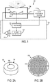
- an exemplary focused ultrasound (“FUS") system 100 for delivering focused ultrasound to a subject 102 is illustrated.
- the FUS system includes a controller 104, an ultrasound transducer 106, an enclosure 108, and a positioning system 110.
- the enclosure 108 houses the ultrasound transducer 106 and provides an interface with the subject 102 such that ultrasound energy can be efficiently transferred from the ultrasound transducer 106 to the subject 102.
- the enclosure 108 may be filled with an acoustic coupling medium 112, which allows for a more efficient propagation of ultrasound energy than through air.
- Exemplary acoustic coupling media 112 include water, such as degassed water.
- the ultrasound transducer 106 includes a signal detector 114, such as a hydrophone.
- the signal detector 114 may include a wideband polyvinylidene fluoride (“PVDF”) hydrophone, such as those described by M.A. O'Reilly and K. Hynynen in "A PVDF Receiver for Ultrasound Monitoring of Transcranial Focused Ultrasound Therapy," IEEE Transactions on Biomedical Engineering, 2010; 57(9):2286-2294 .
- the ultrasound transducer 106 is coupled to the positioning system 110 by way of a support 116.
- the positioning system 110 is advantageously a three-axis positioning system that provides precise and accurate positioning of the ultrasound transducer 106 in three dimensions, but can be, in general, a multi-axis positioning system that provides precise and accurate positioning of the ultrasound transducer 106 in two or more dimensions or directions.
- the controller 104 generally includes a processor 118, a signal generator 120, and a radio frequency (“RF") amplifier 122.
- the signal generator 120 may include, for example, a function generator, and is configured to provide a driving signal that directs the ultrasound transducer 106 to generate ultrasound energy.
- the driving signal produced by the signal generator 120 is amplified by the RF amplifier 122 before being received by the ultrasound transducer 106.
- the controller 104 can be positioned inside or outside of the magnet room of the magnetic resonance imaging (“MRI”) system.
- the processor 118 is in communication with the signal generator 120 and directs the signal generator 120 to produce the driving signal that is delivered to the ultrasound transducer 106. As will be described below in detail, the processor 118 may be configured to adjust properties of the driving signal such that the ultrasound energy pressure produced by the ultrasound transducer 106 is adjusted in accordance with embodiments of the present invention.
- the processor 118 receives acoustic signals from the signal detector 114. As will be described below in detail, the feedback information provided by the signal detector 114 is utilized by the processor 118 to direct the appropriate adjustments in ultrasound energy.
- the processor 118 is also in communication with the positioning system 110, and is configured to direct the positioning system 110 to move the position of the ultrasound transducer 106 during a sonication procedure.
- the controller 104 may adjust the phase and/or amplitude of the driving RF signal to each transducer element to control the location of the focal spot.
- the ultrasound transducer 106 may be referred to as a transducer assembly that includes one or more arrays of ultrasound transducer elements.
- Each transducer array may include only transmit elements, only receive elements, or both transmit and receive elements.
- the transducer assembly may include multiple integrated transmit and receive arrays.
- the transducer assembly may include two or more transmit arrays operating at different frequencies, and one or more receive arrays with resonances at harmonics or subharmonics of the transmit arrays.
- the transducer assembly would be a full hemisphere to provide the best focusing capabilities. All of the arrays can be either fully populated or sparse if a reduced number of transducer elements is preferred.
- the transducer assembly 208 is composed of integrated units 202 that contain a transmit element 204 and a receive element 206.
- the transmit element 204 and receive element 206 are arranged in the integrated unit 202 such that they are coaxial.
- the transmit element 204 can be a circular transducer element nested inside an annular-shaped receive element 206.
- the integrated units 202 can be arrayed over the extent of the transducer assembly 208, as illustrated in FIG. 2B .
- the frequency of the integrated units 202 would increase from the exterior transducer elements of the integrated units 202 to the interior transducer elements of the integrated units 202 so as to keep good directivity at higher frequencies.
- the lowest transmit ultrasound frequency is preferably around 100-300 kHz, where distortions due to the skull are minimal.
- the nested transducer elements in the integrated units 202 are connected to multiplexers in a multiplexer circuit 210 that can, under the direction of a controller, connect the RF-transmit signal to any of the transducer elements capable of transmitting ultrasound energy.
- the multiplexers can connect the receiver electronics to any of the transducer elements that are capable of detecting acoustic signals. It is possible also to connect multiple transducer elements simultaneously to separate transmit and/or receive lines. Two example configurations of the possible connections between integrated transducer units 202 and the multiplexing circuit 210 are illustrated in FIGS. 2C and 2D . In FIG.
- each transducer element in the each integrated transducer unit 202 is connected to a multiplexer that connects that transducer element to both a transmit line and a receive line.
- each integrated transducer unit 202 includes one transducer element that, via the multiplexing circuit, is connected only to a transmit line and one transducer element that, via the multiplexing circuit 210, is connected to both the transmit line and a receive line. It should be appreciated that any suitable combination of connections between transducer elements in the integrated transducer units 202 and the transmit and receive lines can be made via an appropriately configured multiplexing circuit.
- each integrated transducer unit 202 does not need to be connected to the transmit and receive lines in the same manner; rather, one group of integrated transducer units 202 could be connected to the transmit and receive lines in one configuration (e.g., the configuration shown in FIG. 2C ) while another group of integrated transducer units 202 could be connected to the transmit and receive lines in another configuration (e.g., the configuration shown in FIG. 2D ).
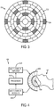
- the transmit elements 302 and the receive elements 304 of a transducer assembly 304 can also be interspersed in a sparse arrangement over the entire array aperture.
- the receiver elements or integrated units could be more sparsely populated within the larger number of transmit elements. Phase delays calculated from the receive elements could then be applied to groups of surrounding transmit elements that would be propagating sound through the same region of the skull bone.
- an FUS system 400 may be configured more particularly for transcranial ultrasound applications in human subjects.
- a subject 402 receives ultrasound energy from a transducer 406 that is configured to surround an extent of the subject's head.
- the transducer 406 may be an approximately hemispherical array of transducer elements.
- the FUS system 400 may include a cooling system, such as a sealed water system with an active cooling and degassing capacity, so that an appropriate temperature of the skull and skin of the subject 402 may be maintained during treatment.
- the FUS system 400 includes a processor 418 that is in communication with a multi-channel amplifier 424 and a multi-channel receiver 426.
- the multi-channel amplifier 424 receives driving signals from the processor 418 and, in turn, directs the transducer elements of the transducer 406 to generate ultrasound energy.
- the multi-channel receiver 426 receives acoustic signals during sonications and relays these signals to the processor 418 for processing in accordance with embodiments of the present invention.
- the processor 418 may also be configured to adjust the driving signals in response to the acoustic signals received by the multi-channel receiver 426.
- the phase and/or amplitude of the driving signals may be adjusted so that ultrasound energy is more efficiently transmitted through the skull of the subject 402 and into the target volume-of-interest 430.
- the acoustic signals may also be analyzed to determine whether and how the extent of the focal region should be adjusted.
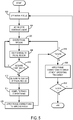
- FIG. 5 illustrates a flowchart setting forth the steps of an example of a method for improving the transmission efficiency of delivering focused ultrasound through skull bone or other bony structures. This example method is described with respect to a transcranial application as follows.
- the ultrasound would be initially focused in the brain using lower frequency ultrasound, as illustrated at step 502. This initial focus would be relatively large due to the low frequency used.
- the patient may then be administered an ultrasound contrast agent, as illustrated at step 504.
- This ultrasound contrast agent may be either a microbubble contrast agent or a phase-change droplet contrast agent, and is preferably administered at a very low concentration.
- the contrast agent concentration can be sufficiently low as to be able to image individual bubbles in the vasculature.
- the low frequency transmit array is then used to excite the individual bubbles, as indicated at step 506. Harmonic emissions that are responsive to this excitation are acquired by one of the receive arrays and beamformed using both phase and amplitude information to produce an initial image of the bubble, as indicated at step 508.
- the initial beamforming considers only geometric delays and not those produced by the skull.
- the excitation and image reconstruction steps are repeated to create a time series of images depicting bubble activity at the transmit focus. To the extent that additional contrast agent is required, more contrast agent will be administered to the subject.
- the approximate center of the transmit focus can be determined from the time series of images, as indicated at step 512.
- phase corrections for the transmitted and received beams are calculated, as indicated at step 514. These phase corrections are then applied to the transmit elements to improve the transmit focus, as indicated at step 516. This process can optionally be repeated to improve the estimates of the transmit and receive phase corrections, as indicated at decision block 518.
- phase corrections could then be applied to the transmit array with the next lowest frequency, creating a time series of images with the corresponding receiver array to determine the spatial extent of the transmit focus and to fine-tune the transmit and receive focusing, as indicated at step 520.
- This process could be iterated at each transmit frequency, and repeated at increasing frequencies to create a sharp treatment focus at high frequencies, as indicated at decision block 522.
- the image quality may be improved by fitting the expected bubble response to the raw data.
- One implementation of this may include finding an optimal fit by cross-correlating a template of the expected bubble response to the raw data on each line.
- the systems and methods of the present invention include providing one or more templates of expected bubble response. Data captured at a low sampling frequency could be up-sampled prior to fitting the template in order to preserve position information.
- the present invention provides the ability to perform high resolution vascular mapping of the brain for diagnostic purposes. This can be accomplished by scanning the transmit focus throughout the brain while collecting the scattered signals from microbubbles that are infused into the blood vessels. In this instance, the transmit and receive signal corrections are derived first and then the three-dimensional images of the bubbles (and thus the vasculature) are formed and tracked as a function of time. For this imaging, either standard short ultrasound imaging bursts can be used to provide time-resolved echo location, or long ultrasound imaging bursts using the method described above can be used to form the images.
- the method of the present invention can also improve ultrasound imaging in other aberrating media, including the breast, the heart, the prostate, and so on. Breast imaging, for example, could be conducted with a similar hemispherical array design as would be used for brain imaging and therapy applications.
Description
- The field of the invention is systems and methods for focused ultrasound ("FUS"). More particularly, the invention relates to systems and methods for efficiently transmitting focused ultrasound through aberrating media, including skull bone and other tissues that may aberrate ultrasound.
- Transcranial focused ultrasound surgery has been clinically investigated for the non-invasive treatment of brain disorders, including chronic pain, essential tremor, and primary brain tumors. Although it is an attractive modality for imaging and therapy in the brain, transcranial ultrasound suffers from the poor propagation of ultrasound through the skull bone, which attenuates and aberrates the beam. At low frequencies, the phase aberrations that result from the heterogeneous and irregular nature of the skull bone are minimal, while at high frequencies phase corrections are required to achieve an ultrasound focus in the brain. The necessary phase delays for these corrections can be determined from computer simulations of the sound propagation through the skull bone, using geometry and bone density information obtained from preoperative computed tomography scans. Even the simplest computational models, however, can take several hours to compute the phase delays.
- A simple direct method for measuring phase delays through an aberrator is to place an ultrasound source at the focus and use time-of-flight measurements to calculate the phase delays between transducer elements. Noninvasive realizations of this technique have used bubbles inside the skull cavity as the sound beacon, with the bubbles either induced through acoustic droplet vaporization or transient cavitation. In one study by Gateau et al., computed tomography-based phase correction was utilized for an initial focusing step and then bubble signature-based phase corrections were used to improve the transducer array focusing and to conduct beam steering. The frequency of the transducer array used by Gateau, et al., was 1 MHz, which was too high to create a cavitation event without first using the simulation based phase correction. In addition, the receivers were a subset of the transmit elements, and were sensitive primarily at their driving frequency.
- In a study by Haworth, et al., it was proposed that bubble-based phase correction could be performed by first sonicating at low frequencies and then using harmonic imaging to calculate the phase delays and refocus at the higher frequency. A device and strategy to perform such phase corrections, however, were not described. In particular, it has not been addressed that bubble activity at the low frequency could occur anywhere within a fairly large transmit focal zone, which could compound targeting errors.
-
US 2004/006272 A1 discloses a system and a method according to the preamble of the independent claims 1 and 7, respectively. - It would therefore be desirable to provide a system and method for efficiently transmitting focused ultrasound through a medium, such as bone.
- The invention is defined by the independent claims 1 and 7. The present invention overcomes the aforementioned drawbacks by providing a system as defined by claim 1 and a method as defined by claim 7 for efficiently transmitting focused ultrasound through a medium, such as bone, using an adaptive focusing scheme. The focal region of the focused ultrasound is iteratively updated to provide an improved focus through the medium. This method may be carried out using a transducer assembly that includes two or more transmit arrays each operating at a different frequency. An initial focus is set and updated by delivering focused ultrasound with a lower frequency transmit array. The phase corrections determined in the first iteration are applied to subsequently higher frequency transmit arrays and the process repeated until a desired focus is achieved.
- It is an aspect to provide a method for adjusting a focus of a focused ultrasound beam. An initial focal region of an ultrasound transducer assembly having a plurality of transmit arrays each having a different operating frequency is defined by setting an initial focus of the transmit arrays. Ultrasound energy is delivered to the initial focal region to excite a contrast agent present in the initial focal region using one of the plurality of transmit arrays. Signals responsive to the excited contrast agent in the initial focal region are then received using the ultrasound transducer array. An image is produced from the received signals, and a center of the initial focal region is determined from this image. Phase correction values are computed using the determined center of the initial focal region, and are applied to the focused ultrasound transducer assembly to update the initial focus, thereby defining an updated focal region that is more focused than the initial focal region. This process is iteratively repeated until the updated focal region corresponds to a desired focus. During each repetition of this process, ultrasound energy is delivered to the updated focal region to excite a contrast agent present in the updated focal region using a different one of the plurality of transmit arrays that operates at a higher frequency than the previous transmit array.
- It is another aspect to provide a transducer assembly for use with a focused ultrasound system. The transducer assembly includes a plurality of integrated transducer units and a multiplexing circuit in communication with the integrated transducer units. Each integrated transducer unit includes at least two transducer elements that are concentrically nested to form the integrated transducer unit. The multiplexing circuit is configured to connect the transducer elements in each integrated transducer unit to at least one of a transmit line and a receive line.
- It is another aspect to provide a focused ultrasound system that includes a transducer assembly and a processor in communication with the transducer assembly. The transducer assembly includes a plurality of transducer arrays each composed of transducer elements, each transducer array operating at a different frequency. The transducer assembly may include at least one additional receive array composed of receive transducer elements. The processor is configured to set a focal region for the transducer assembly and to iteratively update this focal region for each transmit array in the transducer assembly. In each iteration, the processor selects the transmit array having the lowest remaining operating frequency and directs the selected transmit array to excite the initial focal region for that transmit array and directs the at least one receive array to receive signals from the initial focal region. The processor then reconstructs an image of the focal region from the received signals and computes phase correction values from the reconstructed image. The processor then applies the computed phase correction values to the selected transmit array and to the transmit array having the next highest operating frequency.
- The foregoing and other aspects and advantages will appear from the following description. In the description, reference is made to the accompanying drawings which form a part hereof, and in which there is shown by way of illustration a preferred embodiment of the invention. Such embodiment does not necessarily represent the full scope of the invention, however, and reference is made therefore to the claims and herein for interpreting the scope of the invention.
-
-
FIG. 1 is a block diagram of an example of a focused ultrasound system; -
FIG. 2A is an example of an integrated transducer unit that includes a nested transmit transducer and receive transducer; -
FIG. 2B is an example of an array of integrated transducer units; -
FIG. 2C is an example of a multiplexing circuit connected to an integrated transducer unit; -
FIG. 2D is another example of a multiplexing circuit connected to integrated transducer units; -
FIG. 3 is an example of a transducer assembly that includes sparsely distributed receive transducer elements; -
FIG. 4 is a block diagram of an example of a focused ultrasound system configured for transcranial applications; and -
FIG. 5 is a flowchart setting forth the steps of an example of a method for adaptively adjusting the focus of a transducer assembly that includes two or more transmit arrays operating at different frequencies. - A system and method for efficiently transmitting focused ultrasound through skull bone using a focused ultrasound ("FUS") system is provided. Particularly, an ultrasound transducer array design and a method for adaptive ultrasound focusing through the skull bone are provided.
- Referring to
FIG. 1 , an exemplary focused ultrasound ("FUS")system 100 for delivering focused ultrasound to asubject 102 is illustrated. The FUS system includes acontroller 104, anultrasound transducer 106, anenclosure 108, and apositioning system 110. Theenclosure 108 houses theultrasound transducer 106 and provides an interface with the subject 102 such that ultrasound energy can be efficiently transferred from theultrasound transducer 106 to the subject 102. By way of example, theenclosure 108 may be filled with anacoustic coupling medium 112, which allows for a more efficient propagation of ultrasound energy than through air. Exemplaryacoustic coupling media 112 include water, such as degassed water. Advantageously, theultrasound transducer 106 includes asignal detector 114, such as a hydrophone. By way of example, thesignal detector 114 may include a wideband polyvinylidene fluoride ("PVDF") hydrophone, such as those described by M.A. O'Reilly and K. Hynynen in "A PVDF Receiver for Ultrasound Monitoring of Transcranial Focused Ultrasound Therapy," IEEE Transactions on Biomedical Engineering, 2010; 57(9):2286-2294. Theultrasound transducer 106 is coupled to thepositioning system 110 by way of asupport 116. Thepositioning system 110 is advantageously a three-axis positioning system that provides precise and accurate positioning of theultrasound transducer 106 in three dimensions, but can be, in general, a multi-axis positioning system that provides precise and accurate positioning of theultrasound transducer 106 in two or more dimensions or directions. - The
controller 104 generally includes aprocessor 118, asignal generator 120, and a radio frequency ("RF")amplifier 122. Thesignal generator 120 may include, for example, a function generator, and is configured to provide a driving signal that directs theultrasound transducer 106 to generate ultrasound energy. The driving signal produced by thesignal generator 120 is amplified by theRF amplifier 122 before being received by theultrasound transducer 106. When theFUS system 100 is used during a magnetic resonance guided FUS ("MRgFUS") application, thecontroller 104 can be positioned inside or outside of the magnet room of the magnetic resonance imaging ("MRI") system. - The
processor 118 is in communication with thesignal generator 120 and directs thesignal generator 120 to produce the driving signal that is delivered to theultrasound transducer 106. As will be described below in detail, theprocessor 118 may be configured to adjust properties of the driving signal such that the ultrasound energy pressure produced by theultrasound transducer 106 is adjusted in accordance with embodiments of the present invention. - The
processor 118 receives acoustic signals from thesignal detector 114. As will be described below in detail, the feedback information provided by thesignal detector 114 is utilized by theprocessor 118 to direct the appropriate adjustments in ultrasound energy. Theprocessor 118 is also in communication with thepositioning system 110, and is configured to direct thepositioning system 110 to move the position of theultrasound transducer 106 during a sonication procedure. In the case that theultrasound transducer 106 is a phased array transducer, thecontroller 104 may adjust the phase and/or amplitude of the driving RF signal to each transducer element to control the location of the focal spot. - In general, the
ultrasound transducer 106 may be referred to as a transducer assembly that includes one or more arrays of ultrasound transducer elements. Each transducer array may include only transmit elements, only receive elements, or both transmit and receive elements. By way of example, the transducer assembly may include multiple integrated transmit and receive arrays. For instance, the transducer assembly may include two or more transmit arrays operating at different frequencies, and one or more receive arrays with resonances at harmonics or subharmonics of the transmit arrays. Preferably, the transducer assembly would be a full hemisphere to provide the best focusing capabilities. All of the arrays can be either fully populated or sparse if a reduced number of transducer elements is preferred. - In one configuration, such as the one illustrated in
FIGS. 2A and 2B , thetransducer assembly 208 is composed ofintegrated units 202 that contain a transmitelement 204 and a receiveelement 206. The transmitelement 204 and receiveelement 206 are arranged in theintegrated unit 202 such that they are coaxial. For example, the transmitelement 204 can be a circular transducer element nested inside an annular-shaped receiveelement 206. AlthoughFIGS. 2A and 2B depictintegrated units 202 composed of only two transducer elements, it is noted that theintegrated units 202 may also be constructed to include more than two nested transducer elements, each capable of transmission, reception, or both. Theintegrated units 202 can be arrayed over the extent of thetransducer assembly 208, as illustrated inFIG. 2B . In general, the frequency of theintegrated units 202 would increase from the exterior transducer elements of theintegrated units 202 to the interior transducer elements of theintegrated units 202 so as to keep good directivity at higher frequencies. The lowest transmit ultrasound frequency is preferably around 100-300 kHz, where distortions due to the skull are minimal. - With reference to
FIGS. 2C and 2D , the nested transducer elements in theintegrated units 202 are connected to multiplexers in amultiplexer circuit 210 that can, under the direction of a controller, connect the RF-transmit signal to any of the transducer elements capable of transmitting ultrasound energy. Similarly, the multiplexers can connect the receiver electronics to any of the transducer elements that are capable of detecting acoustic signals. It is possible also to connect multiple transducer elements simultaneously to separate transmit and/or receive lines. Two example configurations of the possible connections betweenintegrated transducer units 202 and themultiplexing circuit 210 are illustrated inFIGS. 2C and 2D . InFIG. 2C , each transducer element in the eachintegrated transducer unit 202 is connected to a multiplexer that connects that transducer element to both a transmit line and a receive line. InFIG. 2D , eachintegrated transducer unit 202 includes one transducer element that, via the multiplexing circuit, is connected only to a transmit line and one transducer element that, via themultiplexing circuit 210, is connected to both the transmit line and a receive line. It should be appreciated that any suitable combination of connections between transducer elements in theintegrated transducer units 202 and the transmit and receive lines can be made via an appropriately configured multiplexing circuit. It is also noted that eachintegrated transducer unit 202 does not need to be connected to the transmit and receive lines in the same manner; rather, one group ofintegrated transducer units 202 could be connected to the transmit and receive lines in one configuration (e.g., the configuration shown inFIG. 2C ) while another group ofintegrated transducer units 202 could be connected to the transmit and receive lines in another configuration (e.g., the configuration shown inFIG. 2D ). - Referring now to
FIG. 3 , the transmitelements 302 and the receiveelements 304 of atransducer assembly 304 can also be interspersed in a sparse arrangement over the entire array aperture. In some high power applications there is a need for a large number of transmit elements, however a substantially smaller number of receive elements are necessary to map the contrast agent activity. To reduce the hardware requirements, the receiver elements or integrated units could be more sparsely populated within the larger number of transmit elements. Phase delays calculated from the receive elements could then be applied to groups of surrounding transmit elements that would be propagating sound through the same region of the skull bone. - Referring now to
FIG. 4 , in some instances, anFUS system 400 may be configured more particularly for transcranial ultrasound applications in human subjects. In such a system, a subject 402 receives ultrasound energy from atransducer 406 that is configured to surround an extent of the subject's head. For example, thetransducer 406 may be an approximately hemispherical array of transducer elements. TheFUS system 400 may include a cooling system, such as a sealed water system with an active cooling and degassing capacity, so that an appropriate temperature of the skull and skin of the subject 402 may be maintained during treatment. - The
FUS system 400 includes aprocessor 418 that is in communication with amulti-channel amplifier 424 and amulti-channel receiver 426. Themulti-channel amplifier 424 receives driving signals from theprocessor 418 and, in turn, directs the transducer elements of thetransducer 406 to generate ultrasound energy. Themulti-channel receiver 426 receives acoustic signals during sonications and relays these signals to theprocessor 418 for processing in accordance with embodiments of the present invention. Theprocessor 418 may also be configured to adjust the driving signals in response to the acoustic signals received by themulti-channel receiver 426. For example, the phase and/or amplitude of the driving signals may be adjusted so that ultrasound energy is more efficiently transmitted through the skull of the subject 402 and into the target volume-of-interest 430. Furthermore, the acoustic signals may also be analyzed to determine whether and how the extent of the focal region should be adjusted. - Having described the general structure of a FUS system that implements the present invention, reference is now made to
FIG. 5 , which illustrates a flowchart setting forth the steps of an example of a method for improving the transmission efficiency of delivering focused ultrasound through skull bone or other bony structures. This example method is described with respect to a transcranial application as follows. - Using geometric focusing, and ignoring the skull contributions, the ultrasound would be initially focused in the brain using lower frequency ultrasound, as illustrated at
step 502. This initial focus would be relatively large due to the low frequency used. The patient may then be administered an ultrasound contrast agent, as illustrated atstep 504. This ultrasound contrast agent may be either a microbubble contrast agent or a phase-change droplet contrast agent, and is preferably administered at a very low concentration. For instance, the contrast agent concentration can be sufficiently low as to be able to image individual bubbles in the vasculature. - The low frequency transmit array is then used to excite the individual bubbles, as indicated at
step 506. Harmonic emissions that are responsive to this excitation are acquired by one of the receive arrays and beamformed using both phase and amplitude information to produce an initial image of the bubble, as indicated atstep 508. The initial beamforming considers only geometric delays and not those produced by the skull. As indicated atdecision block 510, the excitation and image reconstruction steps are repeated to create a time series of images depicting bubble activity at the transmit focus. To the extent that additional contrast agent is required, more contrast agent will be administered to the subject. - By examining the spatial extent of the activity and the strength of the bubble responses, the approximate center of the transmit focus can be determined from the time series of images, as indicated at
step 512. Using the emissions from one of the bubble events at this location, phase corrections for the transmitted and received beams are calculated, as indicated atstep 514. These phase corrections are then applied to the transmit elements to improve the transmit focus, as indicated atstep 516. This process can optionally be repeated to improve the estimates of the transmit and receive phase corrections, as indicated atdecision block 518. - The phase corrections could then be applied to the transmit array with the next lowest frequency, creating a time series of images with the corresponding receiver array to determine the spatial extent of the transmit focus and to fine-tune the transmit and receive focusing, as indicated at
step 520. This process could be iterated at each transmit frequency, and repeated at increasing frequencies to create a sharp treatment focus at high frequencies, as indicated atdecision block 522. - In some embodiments, when the bubble signatures recorded at the receivers are very weak, the image quality may be improved by fitting the expected bubble response to the raw data. One implementation of this may include finding an optimal fit by cross-correlating a template of the expected bubble response to the raw data on each line. Thus, in some embodiments the systems and methods of the present invention include providing one or more templates of expected bubble response. Data captured at a low sampling frequency could be up-sampled prior to fitting the template in order to preserve position information.
- The present invention provides the ability to perform high resolution vascular mapping of the brain for diagnostic purposes. This can be accomplished by scanning the transmit focus throughout the brain while collecting the scattered signals from microbubbles that are infused into the blood vessels. In this instance, the transmit and receive signal corrections are derived first and then the three-dimensional images of the bubbles (and thus the vasculature) are formed and tracked as a function of time. For this imaging, either standard short ultrasound imaging bursts can be used to provide time-resolved echo location, or long ultrasound imaging bursts using the method described above can be used to form the images. The method of the present invention can also improve ultrasound imaging in other aberrating media, including the breast, the heart, the prostate, and so on. Breast imaging, for example, could be conducted with a similar hemispherical array design as would be used for brain imaging and therapy applications.
Claims (13)
- A focused ultrasound system (100), comprising:a transducer assembly (106) that includes:a plurality of transmit arrays composed of transmit transducer elements (204), each transmit array operating at a different frequency;at least one receive array composed of receive transducer elements (206);a processor (118) in communication with the transducer assembly (106) and configured to:set a focal region for the transducer assembly;iteratively update the focal region for each transmit array in the transducer assembly by:selecting the transmit array having the lowest remaining operating frequency;directing the selected transmit array to excite the initial focal region for that transmit array;directing the at least one receive array to receive signals from the initial focal region;reconstructing an image of the focal region from the received signals;computing phase correction values from the reconstructed image;
characterised in that the processor is configured to apply the computed phase correction values to the selected transmit array and to the transmit array having the next highest operating frequency. - The focused ultrasound system as recited in claim 1 further comprising a multiplexing circuit (210) in communication with the transducer assembly (106) and configured to allow switching between the plurality of transmit arrays and the at least one receive array.
- The focused ultrasound system as recited in claim 1 in which the at least one receive array is sparsely distributed among the plurality of transmit arrays.
- The focused ultrasound system as recited in claim 1 in which the processor (118) is further configured to:apply the computed phase correction values to the received signals to form phase-corrected signals; andreconstruct an image from the corrected signals.
- The focused ultrasound system as recited in claim 4 in which the processor (118) is configured to scan the focal region of the transducer assembly (106) through a volume-of-interest while receiving signals from the volume-of-interest.
- The focused ultrasound system as recited in claim 4 in which the processor (118) is configured to set multiple simultaneously produced focal regions for the transducer assembly (106) so as to accelerate data acquisition.
- A method for adjusting a focus of a focused ultrasound beam transmitted through an aberrating media, the steps of the method comprising:setting a focal region for a transducer assembly (106) having:a plurality of transmit arrays each operating at a different frequency and composed of transmit transducer elements (204); anda receive array composed of receive transducer elements (206);iteratively updating the focal region for each transmit array in the transducer assembly (106) by:selecting the transmit array having the lowest remaining operating frequency;directing the selected transmit array to excite the initial focal region for that transmit array;directing the at least one receive array to receive signals from the initial focal region;reconstructing an image of the focal region from the received signals;computing phase correction values from the reconstructed image;
characterised inapplying the computed phase correction values to the selected transmit array and to the transmit array having the next highest operating frequency - The method as recited in claim 7, further comprising:a) defining an initial focus region of an ultrasound transducer assembly having a plurality of transmit arrays each having a different operating frequency by setting an initial focus of the transmit arrays;b) delivering ultrasound energy to the initial focal region to excite a contrast agent previously provided to the initial focal region using one of the plurality of transmit arrays;c) receiving signals responsive to the excited contrast agent in the initial focal region using the ultrasound transducer array;d) producing an image from the received signals;e) determining a center of the initial focal region from the produced image;f) computing phase correction values using the determined center of the initial focal region;g) applying the computed phase correction values to the focused ultrasound transducer assembly to update the initial focus, thereby defining an updated focal region that is more focused than the initial focal region;h) repeating steps b)-g) until the updated focal region corresponds to a desired focus, during each repetition delivering ultrasound energy to the updated focal region to excite a contrast agent present in the updated focal region using a different one of the plurality of transmit arrays that operates at a higher frequency than the previous transmit array.
- The method as recited in claim 8 further comprising:i) forming phase-corrected signals by applying the phase correction values computed in step f) to the signals received in step c); andj) and reconstructing an image from the phase-corrected signals.
- The method as recited in claim 9 in which the aberrating media is a skull bone and the image reconstructed from the phase-corrected signals is a high resolution image that depicts vasculature.
- The method as recited in claim 10 in which step b) includes delivering the ultrasound energy to the initial focal region to excite the previously provided contrast agent when it is present in a concentration that is sufficiently low such that the signals received in step c) are spatially separate and each correspond to a single microbubble in the contrast agent.
- The method as recited in claim 11 in which steps b)-j) are repeated over a duration of time such that a plurality of time-resolved images that depict microbubble movement caused by blood flow are reconstructed in step j).
- The method as recited in claim 12 further comprising forming at least one of a dynamic blood flow map and a perfusion map using the plurality of time-resolved images reconstructed in step j).
Applications Claiming Priority (2)
| Application Number | Priority Date | Filing Date | Title |
|---|---|---|---|
| US201361771992P | 2013-03-04 | 2013-03-04 | |
| PCT/US2014/020279 WO2014138050A1 (en) | 2013-03-04 | 2014-03-04 | System and method for measuring and correcting ultrasound phase distortions induced by aberrating media |
Publications (3)
| Publication Number | Publication Date |
|---|---|
| EP2964096A1 EP2964096A1 (en) | 2016-01-13 |
| EP2964096A4 EP2964096A4 (en) | 2017-02-15 |
| EP2964096B1 true EP2964096B1 (en) | 2021-12-15 |
Family
ID=51491864
Family Applications (1)
| Application Number | Title | Priority Date | Filing Date |
|---|---|---|---|
| EP14760248.6A Active EP2964096B1 (en) | 2013-03-04 | 2014-03-04 | System and method for measuring and correcting ultrasound phase distortions induced by aberrating media |
Country Status (6)
| Country | Link |
|---|---|
| US (1) | US11464482B2 (en) |
| EP (1) | EP2964096B1 (en) |
| CN (1) | CN105073016A (en) |
| CA (2) | CA3219245A1 (en) |
| HK (1) | HK1216982A1 (en) |
| WO (1) | WO2014138050A1 (en) |
Cited By (3)
| Publication number | Priority date | Publication date | Assignee | Title |
|---|---|---|---|---|
| US11648424B2 (en) | 2018-11-28 | 2023-05-16 | Histosonics Inc. | Histotripsy systems and methods |
| US11813485B2 (en) | 2020-01-28 | 2023-11-14 | The Regents Of The University Of Michigan | Systems and methods for histotripsy immunosensitization |
| US11819712B2 (en) | 2013-08-22 | 2023-11-21 | The Regents Of The University Of Michigan | Histotripsy using very short ultrasound pulses |
Families Citing this family (11)
| Publication number | Priority date | Publication date | Assignee | Title |
|---|---|---|---|---|
| EP3277377A1 (en) * | 2015-03-30 | 2018-02-07 | Koninklijke Philips N.V. | Ultrasonic transducer array for sonothrombolysis treatment and monitoring |
| CN104856740A (en) * | 2015-04-30 | 2015-08-26 | 江苏汉美科技有限公司 | Combined device for tumor blood capillary embolism with ultrasound micro-bubble contrast agents |
| WO2017114701A1 (en) * | 2015-12-31 | 2017-07-06 | Koninklijke Philips N.V. | System and method for interventional acoustic imaging |
| EP3482390B1 (en) * | 2016-07-08 | 2021-09-08 | Insightec Ltd. | Systems and methods for ensuring coherence between multiple ultrasound transducer arrays |
| JP6934933B2 (en) * | 2016-07-25 | 2021-09-15 | インサイテック リミテッド | Ultrasonic autofocusing with reflection |
| WO2019069113A1 (en) * | 2017-10-03 | 2019-04-11 | Profound Medical Inc. | Multi-channel real-time phase modulation for emi reduction in an ultrasound device |
| US11806554B2 (en) | 2017-10-03 | 2023-11-07 | Profound Medical Inc. | Multi-channel real-time phase modulation for EMI reduction in an ultrasound device |
| US11291866B2 (en) * | 2017-12-11 | 2022-04-05 | Insightec, Ltd. | Ultrasound focusing in dynamically changing media |
| CN108652672B (en) * | 2018-04-02 | 2021-06-22 | 中国科学院深圳先进技术研究院 | Ultrasonic imaging system, method and device |
| KR102141654B1 (en) * | 2018-11-28 | 2020-08-05 | 재단법인 대구경북첨단의료산업진흥재단 | Transmitting and receiving dual mode focused ultrasonic transducer, and micro-bubble cavitation image visualization method using the same |
| CN117379093B (en) * | 2023-12-11 | 2024-03-15 | 深圳英美达医疗技术有限公司 | Ultrasonic imaging method based on ring array transducer and ultrasonic probe system |
Family Cites Families (23)
| Publication number | Priority date | Publication date | Assignee | Title |
|---|---|---|---|---|
| WO1988009939A1 (en) | 1987-06-11 | 1988-12-15 | Commonwealth Of Australia | Ultrasonic beam compensation |
| US5752515A (en) * | 1996-08-21 | 1998-05-19 | Brigham & Women's Hospital | Methods and apparatus for image-guided ultrasound delivery of compounds through the blood-brain barrier |
| FR2773459B1 (en) * | 1998-01-12 | 2000-04-14 | Centre Nat Rech Scient | PROCESS FOR EXPLORING AND VISUALIZING TISSUES OF HUMAN OR ANIMAL ORIGIN FROM A HIGH FREQUENCY ULTRASONIC SENSOR |
| DE19905069A1 (en) * | 1999-02-08 | 2000-08-10 | Planttec Biotechnologie Gmbh | Alternansucrase encoding nucleic acid molecules |
| US6419648B1 (en) | 2000-04-21 | 2002-07-16 | Insightec-Txsonics Ltd. | Systems and methods for reducing secondary hot spots in a phased array focused ultrasound system |
| US6613004B1 (en) | 2000-04-21 | 2003-09-02 | Insightec-Txsonics, Ltd. | Systems and methods for creating longer necrosed volumes using a phased array focused ultrasound system |
| US6612988B2 (en) * | 2000-08-29 | 2003-09-02 | Brigham And Women's Hospital, Inc. | Ultrasound therapy |
| US6770031B2 (en) * | 2000-12-15 | 2004-08-03 | Brigham And Women's Hospital, Inc. | Ultrasound therapy |
| US6705994B2 (en) | 2002-07-08 | 2004-03-16 | Insightec - Image Guided Treatment Ltd | Tissue inhomogeneity correction in ultrasound imaging |
| US7134615B2 (en) * | 2002-07-31 | 2006-11-14 | Caterpillar Inc | Nozzle insert for mixed mode fuel injector |
| US7344509B2 (en) | 2003-04-17 | 2008-03-18 | Kullervo Hynynen | Shear mode therapeutic ultrasound |
| US20060241462A1 (en) | 2005-03-14 | 2006-10-26 | Yi-Hong Chou | Method of intracranial ultrasound imaging and related system |
| US8002705B1 (en) * | 2005-07-22 | 2011-08-23 | Zonaire Medical Systems, Inc. | Continuous transmit focusing method and apparatus for ultrasound imaging system |
| US7963919B2 (en) * | 2005-12-07 | 2011-06-21 | Siemens Medical Solutions Usa, Inc. | Ultrasound imaging transducer array for synthetic aperture |
| US7613076B2 (en) * | 2007-05-31 | 2009-11-03 | Avago Technologies Wireless Ip (Singapore) Pte. Ltd. | Acoustic power transformer including lens |
| US7804228B2 (en) * | 2007-12-18 | 2010-09-28 | Boston Scientific Scimed, Inc. | Composite passive materials for ultrasound transducers |
| JP5235477B2 (en) | 2008-04-14 | 2013-07-10 | キヤノン株式会社 | Ultrasonic image forming method and ultrasonic apparatus |
| CN201200425Y (en) | 2008-05-15 | 2009-03-04 | 上海理工大学 | Ultrasound scanning probe |
| JP5395396B2 (en) * | 2008-10-15 | 2014-01-22 | 株式会社東芝 | Ultrasonic diagnostic apparatus, medical image processing apparatus, and medical image processing program |
| US20110009856A1 (en) * | 2009-07-08 | 2011-01-13 | Glen Jorgensen | Combination Radio Frequency Device for Electrosurgery |
| US9066703B2 (en) * | 2010-06-04 | 2015-06-30 | Kabushiki Kaisha Toshiba | Medical ultrasound 2-D transducer array architecture: spot of arago |
| WO2012006053A1 (en) * | 2010-06-29 | 2012-01-12 | Kullervo Henrik Hynynen | Thermal therapy apparatus and method using focused ultrasonic sound fields |
| JP5435751B2 (en) * | 2011-03-03 | 2014-03-05 | 富士フイルム株式会社 | Ultrasonic diagnostic apparatus, ultrasonic transmission / reception method, and ultrasonic transmission / reception program |
-
2014
- 2014-03-04 CN CN201480011908.0A patent/CN105073016A/en active Pending
- 2014-03-04 CA CA3219245A patent/CA3219245A1/en active Pending
- 2014-03-04 CA CA2898503A patent/CA2898503C/en active Active
- 2014-03-04 US US14/772,316 patent/US11464482B2/en active Active
- 2014-03-04 EP EP14760248.6A patent/EP2964096B1/en active Active
- 2014-03-04 WO PCT/US2014/020279 patent/WO2014138050A1/en active Application Filing
-
2016
- 2016-04-28 HK HK16104908.5A patent/HK1216982A1/en unknown
Non-Patent Citations (1)
| Title |
|---|
| None * |
Cited By (4)
| Publication number | Priority date | Publication date | Assignee | Title |
|---|---|---|---|---|
| US11819712B2 (en) | 2013-08-22 | 2023-11-21 | The Regents Of The University Of Michigan | Histotripsy using very short ultrasound pulses |
| US11648424B2 (en) | 2018-11-28 | 2023-05-16 | Histosonics Inc. | Histotripsy systems and methods |
| US11813484B2 (en) | 2018-11-28 | 2023-11-14 | Histosonics, Inc. | Histotripsy systems and methods |
| US11813485B2 (en) | 2020-01-28 | 2023-11-14 | The Regents Of The University Of Michigan | Systems and methods for histotripsy immunosensitization |
Also Published As
| Publication number | Publication date |
|---|---|
| CA2898503A1 (en) | 2014-09-12 |
| CA2898503C (en) | 2024-01-02 |
| WO2014138050A1 (en) | 2014-09-12 |
| CA3219245A1 (en) | 2014-09-12 |
| HK1216982A1 (en) | 2016-12-16 |
| EP2964096A4 (en) | 2017-02-15 |
| US11464482B2 (en) | 2022-10-11 |
| US20160007954A1 (en) | 2016-01-14 |
| EP2964096A1 (en) | 2016-01-13 |
| CN105073016A (en) | 2015-11-18 |
Similar Documents
| Publication | Publication Date | Title |
|---|---|---|
| EP2964096B1 (en) | System and method for measuring and correcting ultrasound phase distortions induced by aberrating media | |
| US20240041429A1 (en) | Systems and methods for performing transcranial ultrasound therapeutic and imaging procedures | |
| US20230346354A1 (en) | Dual mode ultrasound transducer (dmut) system and method for controlling delivery of ultrasound therapy | |
| Tanter et al. | Compensating for bone interfaces and respiratory motion in high-intensity focused ultrasound | |
| US11872085B2 (en) | Focused ultrasound system with optimized monitoring of cavitation | |
| Clement et al. | Micro-receiver guided transcranial beam steering | |
| Liu et al. | Design and implementation of a transmit/receive ultrasound phased array for brain applications | |
| WO2020058757A1 (en) | Ultrasound focusing utilizing a 3d-printed skull replica | |
| Thies et al. | Real-time visualization of a focused ultrasound beam using ultrasonic backscatter | |
| WO2022106891A1 (en) | Multiparametric optimization for ultrasound procedures | |
| Pernot et al. | High power phased array prototype for clinical high intensity focused ultrasound: applications to transcostal and transcranial therapy | |
| Bendjador et al. | A theranostic 3D ultrasound imaging system for high resolution image-guided therapy | |
| US9247921B2 (en) | Systems and methods of high frame rate streaming for treatment monitoring | |
| Li et al. | Evaluation of advanced Passive Acoustic Mapping (PAM) beamformers for high-duty-cycle HIFU ablated in Ex Vivo Tissue | |
| Vignon et al. | Mapping skull attenuation for optimal probe placement in transcranial ultrasound applications | |
| JP2023530042A (en) | Mapping cavitation activity | |
| O’Brien et al. | Characterization of Image-based Refocusing for Transcranial Therapies | |
| O'Brien et al. | Ultrasound imaging using transmit wavefront synthesis: Spatial and frequency diversity approach to compounding | |
| Tanter et al. | New devices and promising approaches for clinical HIFU applications |
Legal Events
| Date | Code | Title | Description |
|---|---|---|---|
| PUAI | Public reference made under article 153(3) epc to a published international application that has entered the european phase |
Free format text: ORIGINAL CODE: 0009012 |
|
| 17P | Request for examination filed |
Effective date: 20150810 |
|
| AK | Designated contracting states |
Kind code of ref document: A1 Designated state(s): AL AT BE BG CH CY CZ DE DK EE ES FI FR GB GR HR HU IE IS IT LI LT LU LV MC MK MT NL NO PL PT RO RS SE SI SK SM TR |
|
| AX | Request for extension of the european patent |
Extension state: BA ME |
|
| DAX | Request for extension of the european patent (deleted) | ||
| RIC1 | Information provided on ipc code assigned before grant |
Ipc: A61B 8/06 20060101ALN20160921BHEP Ipc: A61B 8/00 20060101ALI20160921BHEP Ipc: A61B 8/08 20060101AFI20160921BHEP |
|
| A4 | Supplementary search report drawn up and despatched |
Effective date: 20170113 |
|
| RIC1 | Information provided on ipc code assigned before grant |
Ipc: A61B 8/08 20060101AFI20170109BHEP Ipc: A61B 8/00 20060101ALI20170109BHEP Ipc: A61B 8/06 20060101ALN20170109BHEP |
|
| STAA | Information on the status of an ep patent application or granted ep patent |
Free format text: STATUS: EXAMINATION IS IN PROGRESS |
|
| 17Q | First examination report despatched |
Effective date: 20200518 |
|
| STAA | Information on the status of an ep patent application or granted ep patent |
Free format text: STATUS: EXAMINATION IS IN PROGRESS |
|
| REG | Reference to a national code |
Ref country code: DE Ref legal event code: R079 Ref document number: 602014081741 Country of ref document: DE Free format text: PREVIOUS MAIN CLASS: A61B0008000000 Ipc: A61B0008080000 |
|
| GRAP | Despatch of communication of intention to grant a patent |
Free format text: ORIGINAL CODE: EPIDOSNIGR1 |
|
| STAA | Information on the status of an ep patent application or granted ep patent |
Free format text: STATUS: GRANT OF PATENT IS INTENDED |
|
| RIC1 | Information provided on ipc code assigned before grant |
Ipc: A61B 8/08 20060101AFI20210611BHEP Ipc: A61B 8/00 20060101ALI20210611BHEP Ipc: A61B 8/06 20060101ALN20210611BHEP |
|
| RIC1 | Information provided on ipc code assigned before grant |
Ipc: A61B 8/08 20060101AFI20210622BHEP Ipc: A61B 8/00 20060101ALI20210622BHEP Ipc: A61B 8/06 20060101ALN20210622BHEP |
|
| INTG | Intention to grant announced |
Effective date: 20210707 |
|
| GRAS | Grant fee paid |
Free format text: ORIGINAL CODE: EPIDOSNIGR3 |
|
| GRAA | (expected) grant |
Free format text: ORIGINAL CODE: 0009210 |
|
| STAA | Information on the status of an ep patent application or granted ep patent |
Free format text: STATUS: THE PATENT HAS BEEN GRANTED |
|
| AK | Designated contracting states |
Kind code of ref document: B1 Designated state(s): AL AT BE BG CH CY CZ DE DK EE ES FI FR GB GR HR HU IE IS IT LI LT LU LV MC MK MT NL NO PL PT RO RS SE SI SK SM TR |
|
| REG | Reference to a national code |
Ref country code: GB Ref legal event code: FG4D Ref country code: CH Ref legal event code: EP |
|
| REG | Reference to a national code |
Ref country code: DE Ref legal event code: R096 Ref document number: 602014081741 Country of ref document: DE |
|
| REG | Reference to a national code |
Ref country code: IE Ref legal event code: FG4D |
|
| REG | Reference to a national code |
Ref country code: AT Ref legal event code: REF Ref document number: 1454868 Country of ref document: AT Kind code of ref document: T Effective date: 20220115 |
|
| REG | Reference to a national code |
Ref country code: LT Ref legal event code: MG9D |
|
| REG | Reference to a national code |
Ref country code: NL Ref legal event code: MP Effective date: 20211215 |
|
| PG25 | Lapsed in a contracting state [announced via postgrant information from national office to epo] |
Ref country code: RS Free format text: LAPSE BECAUSE OF FAILURE TO SUBMIT A TRANSLATION OF THE DESCRIPTION OR TO PAY THE FEE WITHIN THE PRESCRIBED TIME-LIMIT Effective date: 20211215 Ref country code: LT Free format text: LAPSE BECAUSE OF FAILURE TO SUBMIT A TRANSLATION OF THE DESCRIPTION OR TO PAY THE FEE WITHIN THE PRESCRIBED TIME-LIMIT Effective date: 20211215 Ref country code: FI Free format text: LAPSE BECAUSE OF FAILURE TO SUBMIT A TRANSLATION OF THE DESCRIPTION OR TO PAY THE FEE WITHIN THE PRESCRIBED TIME-LIMIT Effective date: 20211215 Ref country code: BG Free format text: LAPSE BECAUSE OF FAILURE TO SUBMIT A TRANSLATION OF THE DESCRIPTION OR TO PAY THE FEE WITHIN THE PRESCRIBED TIME-LIMIT Effective date: 20220315 |
|
| REG | Reference to a national code |
Ref country code: AT Ref legal event code: MK05 Ref document number: 1454868 Country of ref document: AT Kind code of ref document: T Effective date: 20211215 |
|
| PG25 | Lapsed in a contracting state [announced via postgrant information from national office to epo] |
Ref country code: SE Free format text: LAPSE BECAUSE OF FAILURE TO SUBMIT A TRANSLATION OF THE DESCRIPTION OR TO PAY THE FEE WITHIN THE PRESCRIBED TIME-LIMIT Effective date: 20211215 Ref country code: NO Free format text: LAPSE BECAUSE OF FAILURE TO SUBMIT A TRANSLATION OF THE DESCRIPTION OR TO PAY THE FEE WITHIN THE PRESCRIBED TIME-LIMIT Effective date: 20220315 Ref country code: LV Free format text: LAPSE BECAUSE OF FAILURE TO SUBMIT A TRANSLATION OF THE DESCRIPTION OR TO PAY THE FEE WITHIN THE PRESCRIBED TIME-LIMIT Effective date: 20211215 Ref country code: HR Free format text: LAPSE BECAUSE OF FAILURE TO SUBMIT A TRANSLATION OF THE DESCRIPTION OR TO PAY THE FEE WITHIN THE PRESCRIBED TIME-LIMIT Effective date: 20211215 Ref country code: GR Free format text: LAPSE BECAUSE OF FAILURE TO SUBMIT A TRANSLATION OF THE DESCRIPTION OR TO PAY THE FEE WITHIN THE PRESCRIBED TIME-LIMIT Effective date: 20220316 |
|
| PG25 | Lapsed in a contracting state [announced via postgrant information from national office to epo] |
Ref country code: NL Free format text: LAPSE BECAUSE OF FAILURE TO SUBMIT A TRANSLATION OF THE DESCRIPTION OR TO PAY THE FEE WITHIN THE PRESCRIBED TIME-LIMIT Effective date: 20211215 |
|
| PG25 | Lapsed in a contracting state [announced via postgrant information from national office to epo] |
Ref country code: SM Free format text: LAPSE BECAUSE OF FAILURE TO SUBMIT A TRANSLATION OF THE DESCRIPTION OR TO PAY THE FEE WITHIN THE PRESCRIBED TIME-LIMIT Effective date: 20211215 Ref country code: SK Free format text: LAPSE BECAUSE OF FAILURE TO SUBMIT A TRANSLATION OF THE DESCRIPTION OR TO PAY THE FEE WITHIN THE PRESCRIBED TIME-LIMIT Effective date: 20211215 Ref country code: RO Free format text: LAPSE BECAUSE OF FAILURE TO SUBMIT A TRANSLATION OF THE DESCRIPTION OR TO PAY THE FEE WITHIN THE PRESCRIBED TIME-LIMIT Effective date: 20211215 Ref country code: PT Free format text: LAPSE BECAUSE OF FAILURE TO SUBMIT A TRANSLATION OF THE DESCRIPTION OR TO PAY THE FEE WITHIN THE PRESCRIBED TIME-LIMIT Effective date: 20220418 Ref country code: ES Free format text: LAPSE BECAUSE OF FAILURE TO SUBMIT A TRANSLATION OF THE DESCRIPTION OR TO PAY THE FEE WITHIN THE PRESCRIBED TIME-LIMIT Effective date: 20211215 Ref country code: EE Free format text: LAPSE BECAUSE OF FAILURE TO SUBMIT A TRANSLATION OF THE DESCRIPTION OR TO PAY THE FEE WITHIN THE PRESCRIBED TIME-LIMIT Effective date: 20211215 Ref country code: CZ Free format text: LAPSE BECAUSE OF FAILURE TO SUBMIT A TRANSLATION OF THE DESCRIPTION OR TO PAY THE FEE WITHIN THE PRESCRIBED TIME-LIMIT Effective date: 20211215 |
|
| PG25 | Lapsed in a contracting state [announced via postgrant information from national office to epo] |
Ref country code: PL Free format text: LAPSE BECAUSE OF FAILURE TO SUBMIT A TRANSLATION OF THE DESCRIPTION OR TO PAY THE FEE WITHIN THE PRESCRIBED TIME-LIMIT Effective date: 20211215 Ref country code: AT Free format text: LAPSE BECAUSE OF FAILURE TO SUBMIT A TRANSLATION OF THE DESCRIPTION OR TO PAY THE FEE WITHIN THE PRESCRIBED TIME-LIMIT Effective date: 20211215 |
|
| REG | Reference to a national code |
Ref country code: DE Ref legal event code: R097 Ref document number: 602014081741 Country of ref document: DE |
|
| PG25 | Lapsed in a contracting state [announced via postgrant information from national office to epo] |
Ref country code: IS Free format text: LAPSE BECAUSE OF FAILURE TO SUBMIT A TRANSLATION OF THE DESCRIPTION OR TO PAY THE FEE WITHIN THE PRESCRIBED TIME-LIMIT Effective date: 20220415 |
|
| PLBE | No opposition filed within time limit |
Free format text: ORIGINAL CODE: 0009261 |
|
| STAA | Information on the status of an ep patent application or granted ep patent |
Free format text: STATUS: NO OPPOSITION FILED WITHIN TIME LIMIT |
|
| PG25 | Lapsed in a contracting state [announced via postgrant information from national office to epo] |
Ref country code: MC Free format text: LAPSE BECAUSE OF FAILURE TO SUBMIT A TRANSLATION OF THE DESCRIPTION OR TO PAY THE FEE WITHIN THE PRESCRIBED TIME-LIMIT Effective date: 20211215 Ref country code: DK Free format text: LAPSE BECAUSE OF FAILURE TO SUBMIT A TRANSLATION OF THE DESCRIPTION OR TO PAY THE FEE WITHIN THE PRESCRIBED TIME-LIMIT Effective date: 20211215 Ref country code: AL Free format text: LAPSE BECAUSE OF FAILURE TO SUBMIT A TRANSLATION OF THE DESCRIPTION OR TO PAY THE FEE WITHIN THE PRESCRIBED TIME-LIMIT Effective date: 20211215 |
|
| 26N | No opposition filed |
Effective date: 20220916 |
|
| PG25 | Lapsed in a contracting state [announced via postgrant information from national office to epo] |
Ref country code: SI Free format text: LAPSE BECAUSE OF FAILURE TO SUBMIT A TRANSLATION OF THE DESCRIPTION OR TO PAY THE FEE WITHIN THE PRESCRIBED TIME-LIMIT Effective date: 20211215 |
|
| REG | Reference to a national code |
Ref country code: BE Ref legal event code: MM Effective date: 20220331 |
|
| PG25 | Lapsed in a contracting state [announced via postgrant information from national office to epo] |
Ref country code: LU Free format text: LAPSE BECAUSE OF NON-PAYMENT OF DUE FEES Effective date: 20220304 Ref country code: IE Free format text: LAPSE BECAUSE OF NON-PAYMENT OF DUE FEES Effective date: 20220304 |
|
| PG25 | Lapsed in a contracting state [announced via postgrant information from national office to epo] |
Ref country code: BE Free format text: LAPSE BECAUSE OF NON-PAYMENT OF DUE FEES Effective date: 20220331 |
|
| PGFP | Annual fee paid to national office [announced via postgrant information from national office to epo] |
Ref country code: FR Payment date: 20230320 Year of fee payment: 10 |
|
| PG25 | Lapsed in a contracting state [announced via postgrant information from national office to epo] |
Ref country code: IT Free format text: LAPSE BECAUSE OF FAILURE TO SUBMIT A TRANSLATION OF THE DESCRIPTION OR TO PAY THE FEE WITHIN THE PRESCRIBED TIME-LIMIT Effective date: 20211215 |
|
| PGFP | Annual fee paid to national office [announced via postgrant information from national office to epo] |
Ref country code: GB Payment date: 20230323 Year of fee payment: 10 Ref country code: DE Payment date: 20230320 Year of fee payment: 10 |
|
| PGFP | Annual fee paid to national office [announced via postgrant information from national office to epo] |
Ref country code: CH Payment date: 20230402 Year of fee payment: 10 |
|
| PG25 | Lapsed in a contracting state [announced via postgrant information from national office to epo] |
Ref country code: HU Free format text: LAPSE BECAUSE OF FAILURE TO SUBMIT A TRANSLATION OF THE DESCRIPTION OR TO PAY THE FEE WITHIN THE PRESCRIBED TIME-LIMIT; INVALID AB INITIO Effective date: 20140304 |