EP2964063B1 - Thin profile multi-tube burner for gas grill - Google Patents
Thin profile multi-tube burner for gas grill Download PDFInfo
- Publication number
- EP2964063B1 EP2964063B1 EP14759624.1A EP14759624A EP2964063B1 EP 2964063 B1 EP2964063 B1 EP 2964063B1 EP 14759624 A EP14759624 A EP 14759624A EP 2964063 B1 EP2964063 B1 EP 2964063B1
- Authority
- EP
- European Patent Office
- Prior art keywords
- additional
- gas
- manifold
- venturi tube
- burner
- Prior art date
- Legal status (The legal status is an assumption and is not a legal conclusion. Google has not performed a legal analysis and makes no representation as to the accuracy of the status listed.)
- Active
Links
Images


Classifications
-
- A—HUMAN NECESSITIES
- A47—FURNITURE; DOMESTIC ARTICLES OR APPLIANCES; COFFEE MILLS; SPICE MILLS; SUCTION CLEANERS IN GENERAL
- A47J—KITCHEN EQUIPMENT; COFFEE MILLS; SPICE MILLS; APPARATUS FOR MAKING BEVERAGES
- A47J37/00—Baking; Roasting; Grilling; Frying
- A47J37/06—Roasters; Grills; Sandwich grills
- A47J37/07—Roasting devices for outdoor use; Barbecues
- A47J37/0704—Roasting devices for outdoor use; Barbecues with horizontal fire box
- A47J37/0713—Roasting devices for outdoor use; Barbecues with horizontal fire box with gas burners
-
- F—MECHANICAL ENGINEERING; LIGHTING; HEATING; WEAPONS; BLASTING
- F23—COMBUSTION APPARATUS; COMBUSTION PROCESSES
- F23D—BURNERS
- F23D14/00—Burners for combustion of a gas, e.g. of a gas stored under pressure as a liquid
- F23D14/02—Premix gas burners, i.e. in which gaseous fuel is mixed with combustion air upstream of the combustion zone
- F23D14/04—Premix gas burners, i.e. in which gaseous fuel is mixed with combustion air upstream of the combustion zone induction type, e.g. Bunsen burner
- F23D14/10—Premix gas burners, i.e. in which gaseous fuel is mixed with combustion air upstream of the combustion zone induction type, e.g. Bunsen burner with elongated tubular burner head
-
- F—MECHANICAL ENGINEERING; LIGHTING; HEATING; WEAPONS; BLASTING
- F23—COMBUSTION APPARATUS; COMBUSTION PROCESSES
- F23D—BURNERS
- F23D23/00—Assemblies of two or more burners
-
- F—MECHANICAL ENGINEERING; LIGHTING; HEATING; WEAPONS; BLASTING
- F23—COMBUSTION APPARATUS; COMBUSTION PROCESSES
- F23D—BURNERS
- F23D2203/00—Gaseous fuel burners
- F23D2203/10—Flame diffusing means
- F23D2203/101—Flame diffusing means characterised by surface shape
- F23D2203/1012—Flame diffusing means characterised by surface shape tubular
-
- F—MECHANICAL ENGINEERING; LIGHTING; HEATING; WEAPONS; BLASTING
- F23—COMBUSTION APPARATUS; COMBUSTION PROCESSES
- F23D—BURNERS
- F23D2900/00—Special features of, or arrangements for burners using fluid fuels or solid fuels suspended in a carrier gas
- F23D2900/00017—Assembled burner modules
Landscapes
- Engineering & Computer Science (AREA)
- Chemical & Material Sciences (AREA)
- Combustion & Propulsion (AREA)
- Mechanical Engineering (AREA)
- General Engineering & Computer Science (AREA)
- Food Science & Technology (AREA)
- Baking, Grill, Roasting (AREA)
- Gas Burners (AREA)
Description
- In the present art, most gas grills have very bulky fireboxes with several drawbacks: 1) they are heavy to handle and install, and the weight makes them expensive for shipping and handling, 2) they are expensive to make due to more materials, and 3) they are thermally inefficient because of the large volume of the firebox. When several types of present market grills were studied it was understood why the fireboxes were made so bulky. The main reason was the burner design. In the majority of the cases, a single tube burner was used under an average 968 cm2 (150 sq.in. / 17"L x 8-1/2"W) cooking area, although, in some cases, two tube burners with single control valves were used under a 1290 to 1548 cm2 (200 to 240 sq.in.) cooking area. These conventional burner designs require a large fire box to achieve sufficient heat for cooking and to pass combustion tests required for safe use.
-
WO 2010/045638 A1 discloses a burner assembly for a gas barbecue grill having a gas supply comprising at least one burner tube with a front end, a back end and a plurality of gas outlet parts formed therein, a front manifold connected to the front end and a back manifold connected to the back end, both of the manifolds being in fluid communication with the burner tube to allow entry of a flammable gas/air mixture, a venturi tube connected to the front and back manifolds and to the gas supply for transferring gas to the burner assembly, and including at least one flow reducing aperture at the venturi tube / front manifold interface, to at least partially inhibit the entry of the gas/ air mixture. - The problem to be solved was how to make a firebox as thin as possible for a gas grill. To make a thinner firebox, the burner tube needs to be located closer to the cooking grate. The main challenge associated with this approach is the failure of the combustion test that is required for product certification. The limited number of ports on a single tube burner burns the gas with taller and stronger flames which impinge on the cooking grate or radiant element and fails the combustion test. To solve this issue, the burner needs to be designed with multiple tubes so that more burner ports can be accommodated to make flames shorter and weaker to avoid flame impingement. An additional venturi tube or tubes are added, to communicate with multiple manifolds, such as a front and rear manifold. Other adjustments are also made to equalize gas pressure in the form of flow restrictors.
-
-
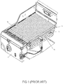
Figure 1 is a partial cutaway view of one type of prior art burner in a grill structure; -
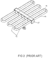
Figure 2 is a perspective view of the type of prior art burner shown inFigure 1 ; -
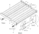
Figure 3 is a perspective view of an example of a thin profile burner; -
Figure 4 is another perspective view of the burner shown inFigure 3 ; -
Figure 5 is a cross-sectional view taken along line 5-5 ofFigure 4 with detail views A and B of the venturi-manifold interface; -
Figure 6 is a perspective view of an alternate example of a thin profile burner; -
Figure 7 is a cross-sectional view taken along line 7-7 ofFigure 6 with detail views C and D of the venturi-manifold interface; -
Figure 8 is a diagrammatical view showing relative profiles of a prior art burner and the thin profile burner assembly according to the present invention; -
Figure 9 is a perspective view, shown partially in cross-section, of an embodiment of the burner assembly according to the present invention, with detail views A and B of the venturi-manifold interface; -
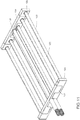
Figure 10 is an exploded, perspective view of another embodiment of the burner assembly according to the present invention; and -
Figure 11 is a perspective view of the burner shown in the preceding figure, here shown in an assembled condition. - Referring now more specifically to the drawings and to
Fig. 1 in particular, 10 designates generally a gas barbecue grill firebox. Firebox 10 is can be mounted on a cart assembly as is well known in the art, or it can be mounted in a stationary construction of appropriate material such as on a post or in an outdoor kitchen. The firebox has afront panel 11 with controls for the gas valves and also for ignition of the gas. Disposed in thefirebox 10 is aparallel tube burner 12. Mounted above theburner 12 is a radiant material, such as ceramic glass ormetal plate 13, which serves as the infrared emitter that is heated by the burner. Mounted above theemitter 13 is acooking grate 14, upon which the food to be cooked is placed. - It can be seen in the cut-away version that the
burner 12 is formed in a grid like arrangement having generally parallel longitudinal members 15 that are connected at each end thereof bysemi-circular conduits 16. The longitudinal members 15 can be formed continuously with thesemi-circular conduits sections 16 or they can be separately formed and assembled into a gas manifold in the center, as shown inFigure 2 . Gas is admitted to the burner tubes by methods known to the art and illustrated inFigures 1 and2 involving a control knob operating a gas valve sending propane gas through suitable conduits to an aspirator where the gas is mixed with primary combustion air and sent to themanifold 21 for distribution to thegas burner tubes 12. In the prior art embodiment shown inFigures 1 and2 , no reduction in the depth of the burner system has been attempted and products of combustion are routed to the front and back of a flat plate re-radiating element. - Ignition of the gas in the burner tubes may be accomplished by use of a spark generator arcing across an electrode (not shown), suitably placed in proximity to the
burner 12, a hot surface igniter similarly placed, and other known methods.Figure 3 is a perspective view of one example of athin profile burner 30. This burner has afront manifold 32, arear manifold 34, and at least oneelongated venturi tube 36, shown here in the center of the burner. The elongated venturi tube is in fluid communication with the front and rear manifolds. Theburner tubes 38 are also in fluid communication with the front and rear manifolds. A suitable combustible gas is introduced into the burner viaventuri tube 40. As the gas enters, it draws some, if not all of the air necessary for combustion throughaspirator 42, in a manner known in the art. For ease of description, the combustible gas/air mixture will generally be referred to herein as the gas supply. - As shown in
Figures 4 and 5 with the detailed views A and B, the gas supply entering the front manifold is restricted with flow restriction means such as relativelysmall holes 39 or baffles (Detail view A) while there is no restriction in the back (Detail view B). In the prior art, the gas would normally have higher pressure in thefront manifold 32 than in therear manifold 34, if prior art burners were constructed with two manifolds, which they are not, by virtue of the gas supply first entering the front manifold. In the prior art burner shown inFigure 2 , the gas has higher pressure in the portions of the burner tubes that are closest to the gas inlet. The baffles orholes 39 at least partially inhibit the entry of the gas supply. The flow restriction means are shown here in the venturi tube. - Prior art constructions would result in relatively strong flames in the front burner tubes and relatively weaker flames in the rear burner tubes. Thus, even heating would be and is, difficult to achieve, with concomitant variations in evenness of cooking, hot spots, and generally inefficient performance. With the restriction holes in the front
manifold supply interface 41 and no restriction in the rearmanifold supply interface 43, gas is evenly distributed and the flames are of substantially equal height tall in the front and back. - Referencing again Detail A in
Figure 5 , instead of the conventional, fully-open, venturi tube of the prior art, flow restrictors in the form ofsmall holes 39 are built into the elongated venturi tube or the manifold itself, at the front venturi manifold interface 47. This contrasts with the fully-open interface 43 of theelongated venturi tube 36 and therear manifold 34. This construction equalizes the gas pressure between the front and rear manifolds and, consequently, in the burner tubes, themselves. The resultant flames when the combustible gas-air mixture is ignited are relatively short and have lesser velocity than is seen in prior art designs. Thus, the burner can have a thinner profile and be located closer to an IR emitter or other radiant material placed between the burner and the cooking grate. - Looking at the detail of
Figure 5 , it will be seen that the elongated venturi tube opens with its full diameter into the rear manifold and through a set of 32 small holes into the front manifold. The ratio of area at the front to area at the rear is 60%. In this case the opening to the rear manifold is at its maximum and cannot be further increased. It will be apparent to those skilled in the art that the difference in the flow resistance between entrance to the rear manifold and the entrance to the front manifold as shown in the detail offigure 5 is greater than that given by the ratio of areas. This is because, given the same initial conditions, the pressure drop across many small openings is much greater than the pressure drop across one large opening of the same area. This is a well known fact of fluid mechanics. - Depending on the size of the burners, the desired flow rate, and the type of gas, variation of the area ratio may be necessary and can be changed by varying the number and size of the holes in the front and by introduction of the feature shown in
Figure 7 in the rear where the area of openings into the rear manifold could be the same as the diameter of the diameter of the venturi tube but flow resistance will be greater. Alternatively, the area of the openings could be made smaller than the area of the venturi tube and still be larger than the openings to the front manifold. - Given these possible variations, the ratio of areas of inlet to the front manifold to the areas of inlet to the back manifold could be from 50% to 70%. Or they could range from 40% to 75%. The object is to balance the pressure and flow in the front and rear manifolds to avoid the undesirable effects outlined previously.
- An alternate example is shown in
Figures 6 and 7 . Here,burner 60 hasfront manifold 62,rear manifold 64, and centralelongated venturi tube 66. In this design, both ends of the venturi tube/front manifold interface 61 and the venturi tube/rear manifold interface 63 are constructed with flow reducing apertures. As shown in Detail views C and D, theapertures 65 at the front interface are smaller than theapertures 67 at the rear interface. The consequent reduction in gas pressure at the front results in equalization of gas pressure between the front and rear manifolds, and thus in the connected burner tubes, themselves. - While the flow restrictors are shown and described as apertures, other means for restricting the gas flow are contemplated, such as slits, gates, valves, and other means known in the art may be utilized.
- Another example exhibits a construction wherein the port sizes in the burner tubes are varied to equalize the gas pressure. In this design, the burner ports nearer or at the center of the tubes are larger than those closer to the ends. This also accomplishes pressure equalization.
- The
burners - After having successful results with the combustion tests, the system was tested thoroughly and had some unexpected results:
- 1) Burner heats up the grate very evenly. Delta-T of this system was within 2.8 °C (5 degree Fahrenheit) versus the conventional systems which have that number from 13,9 to 27,8 °C (25 to 50 degree Fahrenheit).
- 2) System is very energy efficient. With minimum volume of the firebox, wastage of energy is reduced significantly and also as the cooking grate is very close to the burner flame, with a 1927 °C (3500 degree Fahrenheit) temperature, it gets a substantial amount of infrared energy directly from the flames. A conventional system is about 20% to 35% thermally efficient but the present system goes over 40% efficient, depending on the cooking grate used.
- 3) Preheat time is significantly reduced. A conventional grill takes 10 to 15 minutes to preheat, but the present system takes only 2 minutes to preheat. It literally heats up the grate instantly.
- 4) By virtue of the food being closer to the heat source, it receives a higher percentage of IR heat which keeps the food juicier.
- 5) With the present burner system, hot spots are eliminated and with the proper cooking grate system, flare-ups are eliminated as well.
- Thus, the optimum design was achieved to have a thin firebox system. While it depends on the size of the system, on a conventional cooking size of 968 cm2 (150 sq.in. / 17"L x 8-1/2"W) the depth of the firebox 80, (from under the cooking grate to the bottom of the firebox) is usually 10,16 cm (4 inches), (reference dimension A in
Figure 8 ). With the present burner system, the depth/thickness of the firebox 82 can be made to approximately 3,81 cm (1-1/2 inches) thick (reference dimension A' inFigure 8 ). To give an idea of how thin this system can be, both conventional and the present systems are shown diagrammatically inFigure 8 . Note that although there are multiple tubes in the burner, the burner is controlled by only one valve. This, of course, can be varied depending on the size of the grill. This reduction in depth saves on manufacturing costs, replacement costs, and material costs, all while providing performance vastly superior to burners of the prior art. - An embodiment of the burner assembly according to the present invention is shown in
Figure 9 .Burner 90 has alower section 92 and an upper section 94. Each section has front and rear manifolds, 96 and 98 and 100 and 102, respectively.Lower section 92 has twoburner tubes upper manifolds - The flammable gas/air mixture is supplied to the burner through lower and upper
elongated venturi tubes Figures 6 and 7 , this construction results in the equalization of gas pressure in the manifolds, and thus in the connected burner tubes. - The structures shown in
Figures 9-11 illustrate the burner assembly according to the invention constructed in a unique overlapping and interleaved burner structure, thus creating a two segment burner that operates with a dual outlet, single control valve. Such valves are known in the art and need not be described in further detail. The burner sections are secured to one another by means known in the art and may be separable, as for repair or replacement of certain elements, or they may be formed as a single unit, or they may be separate units that are substantially permanently secured together. The operation is such that, for example, the upper section 94, inFigure 9 , can be operated in a low flow/low heat condition. When higher flow/higher temperature is demanded, additional gas/air flow is routed to thelower section 92. Alternately, the operation can be reversed, with the lower section operating as the main or normal burner and the upper section operated as an additional burner to provide a higher than normal heating rate for quickly warming up the grill, cooking in cold conditions, or for very quickly searing meat, among other purposes. -
Figures 10 and11 illustrate a larger version of the burner assembly according to the invention shown inFigure 9 . In the explodedFigure 10 ,lower section 120 has fourlower burner tubes 122 that are in fluid communication with front and rearlower manifolds Upper section 128 has twoupper burner tubes 130, that are in fluid communication with front and rearupper manifolds - As can be seen in
Figure 10 from the respective ends and walls of the upper and lower manifold sections, upon assembly into the burner element shown inFigure 11 , the upper and lower manifolds are separate structures. The lower manifolds supply a gas/air mixture to thelower burner tubes 122 while the upper manifolds supply a gas/air mixture to theupper tubes 130. The burner is supplied with the gas/air mixture through a dual outlet, single control valve, as is known in the art. - As with the operational description above, relative to the burner shown in
Figure 9 , the lower section can be used as the main, or normal burner, with the upper section used to provide a higher than normal heating rate. The relative functions can also be reversed. In addition, all of the burner tubes can be operated simultaneously, to provide a substantially high heat, fast cooking environment, or they can be used separately for slow cooking, warming food, or in combination with flavoring materials, such as wood chips, as in a smoker-type grill. - While an embodiment of a thin profile, multi-manifold multi-tube burner assembly for gas grills and modifications thereof have been shown and described in detail herein, various additional changes and modifications may be made without departing from the scope of the present invention as defined in the appended claims.
Claims (11)
- A burner assembly (90) for a gas barbeque grill, said burner assembly comprising
a plurality of burner tubes (122) with a front end, a back end and a plurality of gas outlet ports formed therein, a front manifold (124) connected to said front end and a back manifold (126) connected to said back end, both of said front and back manifolds (124, 126) being in fluid communication with said burner tubes (122) to allow entry of a flammable gas/air mixture, a venturi tube (110) connected to said front and back manifolds (124, 126) and to a gas supply for transferring gas to the burner assembly (90), flow restrictor being at least one of holes, baffles, flow reducing apertures, slits, gates, valves and varying port sizes at the venturi tube (110) / front manifold (124) interface, to at least partially inhibit the entry of the gas/air mixture; and
a plurality of additional burner tubes (130) with an additional front end, an additional back end, and an additional plurality of gas outlet ports formed therein, an additional front manifold (132) connected to said additional front end and an additional back manifold (134) connected to said additional back end, both of said additional front and back manifolds (132, 134) being in fluid communication with said additional burner tubes (130) to allow entry of a flammable gas/air mixture, an additional venturi tube (112) connected to said additional front and back manifolds (132, 134) and to the gas supply for transferring gas to the burner assembly (90), and an additional flow restrictor being at least one of holes, baffles, flow reducing apertures, slits, gates, valves and varying port sizes at the additional venturi tube (112) / additional front manifold (132) interface,
wherein said front manifold (124) and said additional front manifold (132) overlap, said back manifold (126) and said additional back manifold (134) overlap and said plurality of burner tubes (122) and said plurality of additional burner tubes (130) are interleaved and
wherein one of said venturi tube (110) and said additional venturi tube (112) receives said gas supply from a dual outlet single control valve in a low flow/low heat condition and both of said venturi tube (110) and said additional venturi tube (112) receive said gas supply from said dual outlet single control valve in a higher flow/higher heat condition. - The burner assembly of claim 1, wherein said venturi tube includes a first plurality of flow reducing apertures (114) as said flow restrictor at the venturi tube/front manifold interface, to at least partially inhibit the entry of the gas/air mixture and said additional venturi tube includes a plurality of flow reducing apertures as said flow restrictor at the additional venturi tube/front manifold interface to at least partially inhibit the entry of the gas air mixture.
- A burner assembly as defined in claim 2 in which said venturi tube includes a second plurality of flow reducing apertures (116) as said flow restrictor at the venturi tube/back manifold interface to at least partially inhibit the entry of the gas/air mixture.
- A burner assembly as defined in claim 3. wherein the first plurality of flow reducing apertures are relatively smaller than the second plurality of flow reducing apertures.
- A burner assembly as defined in claim 2 in which said additional venturi tube includes a fourth plurality of flow reducing apertures (116) as said flow restrictor at the additional venturi tube/back manifold interface to at least partially inhibit the entry of the gas/air mixture.
- A burner assembly as defined in claim 1, wherein said front manifold includes a first baffle as said flow restrictor to at least partially inhibit the entry of the gas/air mixture.
- A burner assembly as defined in claim 6 in which said back manifold includes a second baffle as said flow restrictor to at least partially inhibit the entry of the gas/air mixture.
- A burner assembly as defined in claim 6, wherein the first baffle comprises relatively smaller openings and the second baffle comprises relatively larger openings.
- A burner assembly as defined in claim 6, wherein said additional front manifold includes a third baffle as said flow restrictor to at least partially inhibit the entry of the gas air mixture.
- A burner assembly as defined in claim 9 in which said additional back manifold includes a fourth baffle as said flow restrictor to at least partially inhibit the entry of the gas/air mixture.
- A burner assembly as defined in claim 10, wherein the third baffle comprises relatively smaller openings and the fourth baffle comprises relatively larger openings.
Applications Claiming Priority (2)
| Application Number | Priority Date | Filing Date | Title |
|---|---|---|---|
| US201361772828P | 2013-03-05 | 2013-03-05 | |
| PCT/US2014/020884 WO2014138294A2 (en) | 2013-03-05 | 2014-03-05 | Thin profile multi-tube burner for gas grill |
Publications (3)
| Publication Number | Publication Date |
|---|---|
| EP2964063A2 EP2964063A2 (en) | 2016-01-13 |
| EP2964063A4 EP2964063A4 (en) | 2016-11-16 |
| EP2964063B1 true EP2964063B1 (en) | 2020-05-20 |
Family
ID=51486265
Family Applications (1)
| Application Number | Title | Priority Date | Filing Date |
|---|---|---|---|
| EP14759624.1A Active EP2964063B1 (en) | 2013-03-05 | 2014-03-05 | Thin profile multi-tube burner for gas grill |
Country Status (6)
| Country | Link |
|---|---|
| US (2) | US20140251302A1 (en) |
| EP (1) | EP2964063B1 (en) |
| CN (1) | CN105246382B (en) |
| CA (1) | CA2904007A1 (en) |
| DK (1) | DK2964063T3 (en) |
| WO (1) | WO2014138294A2 (en) |
Families Citing this family (11)
| Publication number | Priority date | Publication date | Assignee | Title |
|---|---|---|---|---|
| CN103948328B (en) * | 2014-03-20 | 2017-01-04 | 江门市卡迪慧亚金属制品有限公司 | Portable samming fuel gas oven |
| USD754475S1 (en) * | 2014-07-07 | 2016-04-26 | Industrial Revolution, Inc. | Stowed portable grill |
| USD792741S1 (en) * | 2015-06-08 | 2017-07-25 | Shu-Jui Chung | Burner of gas grill |
| US20170074509A1 (en) * | 2015-09-11 | 2017-03-16 | Green Air Burner Systems, LLC | Hydrocarbon Burner |
| FR3042022A1 (en) * | 2015-10-02 | 2017-04-07 | Matit | MULTI-FUNCTION GAS COOKING APPLIANCE FOR EXTERNAL USE, HAVING ONE OR MORE BURNERS WITH AT LEAST 3 PARALLEL RAMPS EACH HAVING A GAS OPENING AND REGULATING CONTROL |
| CA3034140A1 (en) * | 2016-08-18 | 2018-02-22 | Brown, Phillip | A cooker |
| US20190093885A1 (en) * | 2017-09-25 | 2019-03-28 | Weber-Stephen Products Llc | Single valve for gas grill with multiple burners |
| GB2599424A (en) * | 2020-10-01 | 2022-04-06 | Bosch Thermotechnology Ltd Uk | An air-gas mixture burning appliance with a gas flow distance regulating device |
| US11940158B2 (en) | 2021-04-16 | 2024-03-26 | Weber-Stephen Products Llc | Dual-burner assemblies for cookboxes of gas grills |
| USD1005769S1 (en) | 2021-09-08 | 2023-11-28 | Newage Products Inc. | Oven |
| WO2023164070A1 (en) * | 2022-02-23 | 2023-08-31 | W.C. Bradley Co. | Burner system for advanced grill |
Family Cites Families (12)
| Publication number | Priority date | Publication date | Assignee | Title |
|---|---|---|---|---|
| US585631A (en) * | 1897-06-29 | Frank a | ||
| US1396211A (en) * | 1920-08-03 | 1921-11-08 | Hubert R Humphrey | Gas-burner |
| US2253834A (en) * | 1939-12-26 | 1941-08-26 | Sulzer Ag | Gas-heated cooking grill |
| US4356810A (en) * | 1981-02-17 | 1982-11-02 | William J. Ferlin | Plural burner gas cooker |
| US6705307B2 (en) * | 2002-05-15 | 2004-03-16 | Weber-Stephens Product Co. | Removable gas burner unit for barbecue grill |
| US7959433B2 (en) * | 2005-08-29 | 2011-06-14 | Meco Corporation | Highly controllable gas grill burner system |
| NZ568596A (en) * | 2006-08-17 | 2009-09-25 | Sunbeam Corp | A burner and a flame tamer for a gas cooker |
| WO2009088809A1 (en) * | 2008-01-02 | 2009-07-16 | W.C. Bradley Company | Temperature measurement means for cooking appliances |
| BRPI0822461A2 (en) * | 2008-06-23 | 2015-09-29 | Sabaf Spa | gas burner for oven or grill and oven or grill |
| US9317046B2 (en) * | 2008-07-03 | 2016-04-19 | Mike Gum | Variable output heating control system |
| WO2010045638A1 (en) * | 2008-10-17 | 2010-04-22 | Char-Broil, Llc | Parallel tube burner with improved cooling and reduced size |
| JP5929596B2 (en) | 2012-07-31 | 2016-06-08 | 株式会社デンソー | Motor drive device |
-
2014
- 2014-03-05 CN CN201480025304.1A patent/CN105246382B/en active Active
- 2014-03-05 EP EP14759624.1A patent/EP2964063B1/en active Active
- 2014-03-05 US US14/198,176 patent/US20140251302A1/en not_active Abandoned
- 2014-03-05 WO PCT/US2014/020884 patent/WO2014138294A2/en active Application Filing
- 2014-03-05 DK DK14759624.1T patent/DK2964063T3/en active
- 2014-03-05 CA CA2904007A patent/CA2904007A1/en not_active Abandoned
-
2018
- 2018-01-25 US US15/880,268 patent/US10856692B2/en active Active
Non-Patent Citations (1)
| Title |
|---|
| None * |
Also Published As
| Publication number | Publication date |
|---|---|
| WO2014138294A2 (en) | 2014-09-12 |
| WO2014138294A3 (en) | 2014-10-30 |
| US20140251302A1 (en) | 2014-09-11 |
| US10856692B2 (en) | 2020-12-08 |
| DK2964063T3 (en) | 2020-06-22 |
| EP2964063A2 (en) | 2016-01-13 |
| US20180228316A1 (en) | 2018-08-16 |
| CA2904007A1 (en) | 2014-09-12 |
| CN105246382A (en) | 2016-01-13 |
| CN105246382B (en) | 2017-12-12 |
| EP2964063A4 (en) | 2016-11-16 |
Similar Documents
| Publication | Publication Date | Title |
|---|---|---|
| US10856692B2 (en) | Thin profile multi-tube burner for gas grill | |
| EP2384135B1 (en) | Methods and apparatus for generating infrared radiation from convective products of combustion | |
| WO2008109633A2 (en) | Charbroiler with improved heat distribution | |
| US8662070B2 (en) | Cooking system for gas grills | |
| US7887321B2 (en) | Burner plate assembly for a gas oven | |
| US5909533A (en) | Electric cooking oven with infrared gas broiler | |
| WO2006009932A1 (en) | Infrared emitting apparatus | |
| US8875622B2 (en) | Heat transfer element for barbecue grill | |
| CN102186389A (en) | Parallel tube burner with improved cooling and reduced size | |
| AU2009210553A1 (en) | Open loop gas burner | |
| US9188343B2 (en) | Oven appliance and a gas burner assembly for the same | |
| CN110139588A (en) | Subregion barbecue grill with transmitting setting | |
| US20140196713A1 (en) | Gas burner assembly for an oven appliance | |
| JP5546498B2 (en) | Grill cookware | |
| US2664877A (en) | Oven construction for ranges | |
| US20110186034A1 (en) | Cooking Appliance | |
| EP3700398B1 (en) | Grilling device with pressurised air supply | |
| JPH0774687B2 (en) | Gas combustion device and gas heating cooker | |
| WO2003040626A1 (en) | Convection oven with gas burner | |
| KR100475725B1 (en) | Burner unit for gas range |
Legal Events
| Date | Code | Title | Description |
|---|---|---|---|
| PUAI | Public reference made under article 153(3) epc to a published international application that has entered the european phase |
Free format text: ORIGINAL CODE: 0009012 |
|
| 17P | Request for examination filed |
Effective date: 20150928 |
|
| AK | Designated contracting states |
Kind code of ref document: A2 Designated state(s): AL AT BE BG CH CY CZ DE DK EE ES FI FR GB GR HR HU IE IS IT LI LT LU LV MC MK MT NL NO PL PT RO RS SE SI SK SM TR |
|
| AX | Request for extension of the european patent |
Extension state: BA ME |
|
| DAX | Request for extension of the european patent (deleted) | ||
| REG | Reference to a national code |
Ref country code: DE Ref legal event code: R079 Ref document number: 602014065709 Country of ref document: DE Free format text: PREVIOUS MAIN CLASS: A47J0037000000 Ipc: A47J0037070000 |
|
| A4 | Supplementary search report drawn up and despatched |
Effective date: 20161013 |
|
| RIC1 | Information provided on ipc code assigned before grant |
Ipc: F23D 14/10 20060101ALI20161007BHEP Ipc: F23D 23/00 20060101ALI20161007BHEP Ipc: A47J 37/07 20060101AFI20161007BHEP |
|
| STAA | Information on the status of an ep patent application or granted ep patent |
Free format text: STATUS: EXAMINATION IS IN PROGRESS |
|
| 17Q | First examination report despatched |
Effective date: 20181012 |
|
| GRAP | Despatch of communication of intention to grant a patent |
Free format text: ORIGINAL CODE: EPIDOSNIGR1 |
|
| STAA | Information on the status of an ep patent application or granted ep patent |
Free format text: STATUS: GRANT OF PATENT IS INTENDED |
|
| INTG | Intention to grant announced |
Effective date: 20191202 |
|
| GRAS | Grant fee paid |
Free format text: ORIGINAL CODE: EPIDOSNIGR3 |
|
| GRAA | (expected) grant |
Free format text: ORIGINAL CODE: 0009210 |
|
| STAA | Information on the status of an ep patent application or granted ep patent |
Free format text: STATUS: THE PATENT HAS BEEN GRANTED |
|
| AK | Designated contracting states |
Kind code of ref document: B1 Designated state(s): AL AT BE BG CH CY CZ DE DK EE ES FI FR GB GR HR HU IE IS IT LI LT LU LV MC MK MT NL NO PL PT RO RS SE SI SK SM TR |
|
| REG | Reference to a national code |
Ref country code: GB Ref legal event code: FG4D |
|
| REG | Reference to a national code |
Ref country code: CH Ref legal event code: EP |
|
| REG | Reference to a national code |
Ref country code: DE Ref legal event code: R096 Ref document number: 602014065709 Country of ref document: DE |
|
| REG | Reference to a national code |
Ref country code: AT Ref legal event code: REF Ref document number: 1272039 Country of ref document: AT Kind code of ref document: T Effective date: 20200615 |
|
| REG | Reference to a national code |
Ref country code: DK Ref legal event code: T3 Effective date: 20200616 |
|
| REG | Reference to a national code |
Ref country code: LT Ref legal event code: MG4D |
|
| REG | Reference to a national code |
Ref country code: NL Ref legal event code: MP Effective date: 20200520 |
|
| PG25 | Lapsed in a contracting state [announced via postgrant information from national office to epo] |
Ref country code: GR Free format text: LAPSE BECAUSE OF FAILURE TO SUBMIT A TRANSLATION OF THE DESCRIPTION OR TO PAY THE FEE WITHIN THE PRESCRIBED TIME-LIMIT Effective date: 20200821 Ref country code: FI Free format text: LAPSE BECAUSE OF FAILURE TO SUBMIT A TRANSLATION OF THE DESCRIPTION OR TO PAY THE FEE WITHIN THE PRESCRIBED TIME-LIMIT Effective date: 20200520 Ref country code: PT Free format text: LAPSE BECAUSE OF FAILURE TO SUBMIT A TRANSLATION OF THE DESCRIPTION OR TO PAY THE FEE WITHIN THE PRESCRIBED TIME-LIMIT Effective date: 20200921 Ref country code: LT Free format text: LAPSE BECAUSE OF FAILURE TO SUBMIT A TRANSLATION OF THE DESCRIPTION OR TO PAY THE FEE WITHIN THE PRESCRIBED TIME-LIMIT Effective date: 20200520 Ref country code: NO Free format text: LAPSE BECAUSE OF FAILURE TO SUBMIT A TRANSLATION OF THE DESCRIPTION OR TO PAY THE FEE WITHIN THE PRESCRIBED TIME-LIMIT Effective date: 20200820 Ref country code: SE Free format text: LAPSE BECAUSE OF FAILURE TO SUBMIT A TRANSLATION OF THE DESCRIPTION OR TO PAY THE FEE WITHIN THE PRESCRIBED TIME-LIMIT Effective date: 20200520 Ref country code: IS Free format text: LAPSE BECAUSE OF FAILURE TO SUBMIT A TRANSLATION OF THE DESCRIPTION OR TO PAY THE FEE WITHIN THE PRESCRIBED TIME-LIMIT Effective date: 20200920 |
|
| PG25 | Lapsed in a contracting state [announced via postgrant information from national office to epo] |
Ref country code: BG Free format text: LAPSE BECAUSE OF FAILURE TO SUBMIT A TRANSLATION OF THE DESCRIPTION OR TO PAY THE FEE WITHIN THE PRESCRIBED TIME-LIMIT Effective date: 20200820 Ref country code: RS Free format text: LAPSE BECAUSE OF FAILURE TO SUBMIT A TRANSLATION OF THE DESCRIPTION OR TO PAY THE FEE WITHIN THE PRESCRIBED TIME-LIMIT Effective date: 20200520 Ref country code: HR Free format text: LAPSE BECAUSE OF FAILURE TO SUBMIT A TRANSLATION OF THE DESCRIPTION OR TO PAY THE FEE WITHIN THE PRESCRIBED TIME-LIMIT Effective date: 20200520 Ref country code: LV Free format text: LAPSE BECAUSE OF FAILURE TO SUBMIT A TRANSLATION OF THE DESCRIPTION OR TO PAY THE FEE WITHIN THE PRESCRIBED TIME-LIMIT Effective date: 20200520 |
|
| REG | Reference to a national code |
Ref country code: AT Ref legal event code: MK05 Ref document number: 1272039 Country of ref document: AT Kind code of ref document: T Effective date: 20200520 |
|
| PG25 | Lapsed in a contracting state [announced via postgrant information from national office to epo] |
Ref country code: AL Free format text: LAPSE BECAUSE OF FAILURE TO SUBMIT A TRANSLATION OF THE DESCRIPTION OR TO PAY THE FEE WITHIN THE PRESCRIBED TIME-LIMIT Effective date: 20200520 Ref country code: NL Free format text: LAPSE BECAUSE OF FAILURE TO SUBMIT A TRANSLATION OF THE DESCRIPTION OR TO PAY THE FEE WITHIN THE PRESCRIBED TIME-LIMIT Effective date: 20200520 |
|
| PG25 | Lapsed in a contracting state [announced via postgrant information from national office to epo] |
Ref country code: ES Free format text: LAPSE BECAUSE OF FAILURE TO SUBMIT A TRANSLATION OF THE DESCRIPTION OR TO PAY THE FEE WITHIN THE PRESCRIBED TIME-LIMIT Effective date: 20200520 Ref country code: AT Free format text: LAPSE BECAUSE OF FAILURE TO SUBMIT A TRANSLATION OF THE DESCRIPTION OR TO PAY THE FEE WITHIN THE PRESCRIBED TIME-LIMIT Effective date: 20200520 Ref country code: CZ Free format text: LAPSE BECAUSE OF FAILURE TO SUBMIT A TRANSLATION OF THE DESCRIPTION OR TO PAY THE FEE WITHIN THE PRESCRIBED TIME-LIMIT Effective date: 20200520 Ref country code: RO Free format text: LAPSE BECAUSE OF FAILURE TO SUBMIT A TRANSLATION OF THE DESCRIPTION OR TO PAY THE FEE WITHIN THE PRESCRIBED TIME-LIMIT Effective date: 20200520 Ref country code: EE Free format text: LAPSE BECAUSE OF FAILURE TO SUBMIT A TRANSLATION OF THE DESCRIPTION OR TO PAY THE FEE WITHIN THE PRESCRIBED TIME-LIMIT Effective date: 20200520 Ref country code: SM Free format text: LAPSE BECAUSE OF FAILURE TO SUBMIT A TRANSLATION OF THE DESCRIPTION OR TO PAY THE FEE WITHIN THE PRESCRIBED TIME-LIMIT Effective date: 20200520 Ref country code: IT Free format text: LAPSE BECAUSE OF FAILURE TO SUBMIT A TRANSLATION OF THE DESCRIPTION OR TO PAY THE FEE WITHIN THE PRESCRIBED TIME-LIMIT Effective date: 20200520 |
|
| REG | Reference to a national code |
Ref country code: DE Ref legal event code: R097 Ref document number: 602014065709 Country of ref document: DE |
|
| PG25 | Lapsed in a contracting state [announced via postgrant information from national office to epo] |
Ref country code: SK Free format text: LAPSE BECAUSE OF FAILURE TO SUBMIT A TRANSLATION OF THE DESCRIPTION OR TO PAY THE FEE WITHIN THE PRESCRIBED TIME-LIMIT Effective date: 20200520 Ref country code: PL Free format text: LAPSE BECAUSE OF FAILURE TO SUBMIT A TRANSLATION OF THE DESCRIPTION OR TO PAY THE FEE WITHIN THE PRESCRIBED TIME-LIMIT Effective date: 20200520 |
|
| PLBE | No opposition filed within time limit |
Free format text: ORIGINAL CODE: 0009261 |
|
| STAA | Information on the status of an ep patent application or granted ep patent |
Free format text: STATUS: NO OPPOSITION FILED WITHIN TIME LIMIT |
|
| 26N | No opposition filed |
Effective date: 20210223 |
|
| PG25 | Lapsed in a contracting state [announced via postgrant information from national office to epo] |
Ref country code: SI Free format text: LAPSE BECAUSE OF FAILURE TO SUBMIT A TRANSLATION OF THE DESCRIPTION OR TO PAY THE FEE WITHIN THE PRESCRIBED TIME-LIMIT Effective date: 20200520 |
|
| PG25 | Lapsed in a contracting state [announced via postgrant information from national office to epo] |
Ref country code: MC Free format text: LAPSE BECAUSE OF FAILURE TO SUBMIT A TRANSLATION OF THE DESCRIPTION OR TO PAY THE FEE WITHIN THE PRESCRIBED TIME-LIMIT Effective date: 20200520 |
|
| REG | Reference to a national code |
Ref country code: CH Ref legal event code: PL |
|
| GBPC | Gb: european patent ceased through non-payment of renewal fee |
Effective date: 20210305 |
|
| REG | Reference to a national code |
Ref country code: BE Ref legal event code: MM Effective date: 20210331 |
|
| PG25 | Lapsed in a contracting state [announced via postgrant information from national office to epo] |
Ref country code: LI Free format text: LAPSE BECAUSE OF NON-PAYMENT OF DUE FEES Effective date: 20210331 Ref country code: LU Free format text: LAPSE BECAUSE OF NON-PAYMENT OF DUE FEES Effective date: 20210305 Ref country code: CH Free format text: LAPSE BECAUSE OF NON-PAYMENT OF DUE FEES Effective date: 20210331 Ref country code: GB Free format text: LAPSE BECAUSE OF NON-PAYMENT OF DUE FEES Effective date: 20210305 Ref country code: IE Free format text: LAPSE BECAUSE OF NON-PAYMENT OF DUE FEES Effective date: 20210305 |
|
| PG25 | Lapsed in a contracting state [announced via postgrant information from national office to epo] |
Ref country code: BE Free format text: LAPSE BECAUSE OF NON-PAYMENT OF DUE FEES Effective date: 20210331 |
|
| PGFP | Annual fee paid to national office [announced via postgrant information from national office to epo] |
Ref country code: FR Payment date: 20230327 Year of fee payment: 10 Ref country code: DK Payment date: 20230329 Year of fee payment: 10 |
|
| PG25 | Lapsed in a contracting state [announced via postgrant information from national office to epo] |
Ref country code: HU Free format text: LAPSE BECAUSE OF FAILURE TO SUBMIT A TRANSLATION OF THE DESCRIPTION OR TO PAY THE FEE WITHIN THE PRESCRIBED TIME-LIMIT; INVALID AB INITIO Effective date: 20140305 |
|
| PGFP | Annual fee paid to national office [announced via postgrant information from national office to epo] |
Ref country code: DE Payment date: 20230329 Year of fee payment: 10 |
|
| PG25 | Lapsed in a contracting state [announced via postgrant information from national office to epo] |
Ref country code: CY Free format text: LAPSE BECAUSE OF FAILURE TO SUBMIT A TRANSLATION OF THE DESCRIPTION OR TO PAY THE FEE WITHIN THE PRESCRIBED TIME-LIMIT Effective date: 20200520 |
|
| P01 | Opt-out of the competence of the unified patent court (upc) registered |
Effective date: 20230527 |