EP2963673A1 - Computational scanning microscopy with improved resolution - Google Patents
Computational scanning microscopy with improved resolution Download PDFInfo
- Publication number
- EP2963673A1 EP2963673A1 EP15174190.7A EP15174190A EP2963673A1 EP 2963673 A1 EP2963673 A1 EP 2963673A1 EP 15174190 A EP15174190 A EP 15174190A EP 2963673 A1 EP2963673 A1 EP 2963673A1
- Authority
- EP
- European Patent Office
- Prior art keywords
- specimen
- point
- irradiate
- beam configuration
- probing
- Prior art date
- Legal status (The legal status is an assumption and is not a legal conclusion. Google has not performed a legal analysis and makes no representation as to the accuracy of the status listed.)
- Granted
Links
Images




Classifications
-
- G—PHYSICS
- G02—OPTICS
- G02B—OPTICAL ELEMENTS, SYSTEMS OR APPARATUS
- G02B21/00—Microscopes
- G02B21/0004—Microscopes specially adapted for specific applications
- G02B21/002—Scanning microscopes
-
- H—ELECTRICITY
- H01—ELECTRIC ELEMENTS
- H01J—ELECTRIC DISCHARGE TUBES OR DISCHARGE LAMPS
- H01J37/00—Discharge tubes with provision for introducing objects or material to be exposed to the discharge, e.g. for the purpose of examination or processing thereof
- H01J37/02—Details
- H01J37/244—Detectors; Associated components or circuits therefor
-
- G—PHYSICS
- G02—OPTICS
- G02B—OPTICAL ELEMENTS, SYSTEMS OR APPARATUS
- G02B21/00—Microscopes
- G02B21/0004—Microscopes specially adapted for specific applications
- G02B21/002—Scanning microscopes
- G02B21/0024—Confocal scanning microscopes (CSOMs) or confocal "macroscopes"; Accessories which are not restricted to use with CSOMs, e.g. sample holders
- G02B21/008—Details of detection or image processing, including general computer control
-
- H—ELECTRICITY
- H01—ELECTRIC ELEMENTS
- H01J—ELECTRIC DISCHARGE TUBES OR DISCHARGE LAMPS
- H01J37/00—Discharge tubes with provision for introducing objects or material to be exposed to the discharge, e.g. for the purpose of examination or processing thereof
- H01J37/02—Details
- H01J37/22—Optical, image processing or photographic arrangements associated with the tube
- H01J37/222—Image processing arrangements associated with the tube
-
- H—ELECTRICITY
- H01—ELECTRIC ELEMENTS
- H01J—ELECTRIC DISCHARGE TUBES OR DISCHARGE LAMPS
- H01J37/00—Discharge tubes with provision for introducing objects or material to be exposed to the discharge, e.g. for the purpose of examination or processing thereof
- H01J37/26—Electron or ion microscopes; Electron or ion diffraction tubes
- H01J37/28—Electron or ion microscopes; Electron or ion diffraction tubes with scanning beams
-
- H—ELECTRICITY
- H01—ELECTRIC ELEMENTS
- H01J—ELECTRIC DISCHARGE TUBES OR DISCHARGE LAMPS
- H01J37/00—Discharge tubes with provision for introducing objects or material to be exposed to the discharge, e.g. for the purpose of examination or processing thereof
- H01J37/26—Electron or ion microscopes; Electron or ion diffraction tubes
- H01J37/285—Emission microscopes, e.g. field-emission microscopes
-
- H—ELECTRICITY
- H01—ELECTRIC ELEMENTS
- H01J—ELECTRIC DISCHARGE TUBES OR DISCHARGE LAMPS
- H01J2237/00—Discharge tubes exposing object to beam, e.g. for analysis treatment, etching, imaging
- H01J2237/22—Treatment of data
- H01J2237/226—Image reconstruction
Definitions
- the invention relates to a method of accumulating an image of a specimen using a scanning-type microscope, comprising the following steps:
- the invention also relates to a scanning-type microscope in which such a method can be performed.
- Charged-particle microscopy is a well-known and increasingly important technique for imaging microscopic objects, particularly in the form of electron microscopy.
- the basic genus of electron microscope has undergone evolution into a number of well-known apparatus species, such as the Transmission Electron Microscope (TEM), Scanning Electron Microscope (SEM), and Scanning Transmission Electron Microscope (STEM), and also into various sub-species, such as so-called “dual-beam” tools (e.g. a FIB-SEM), which additionally employ a "machining" Focused Ion Beam (FIB), allowing supportive activities such as ion-beam milling or Ion-Beam-Induced Deposition (IBID), for example. More specifically:
- confocal microscopy in which scanning irradiation by a point source of photons stimulates localized emanation of fluorescence radiation from the specimen.
- a detector can be used to collect (part of) this flux of fluorescence radiation and accumulate an image on the basis thereof. More information on this topic can, for example, be gleaned from the following Wikipedia link:
- a scanning-type microscope will comprise at least the following components:
- a spatial variable V demonstrates a value V k at an associated discrete depth level L k referenced to the surface S, k being a member of an integer sequence
- spatial variable V representing a physical property of the specimen as a function of position in its bulk, e.g. contrast, intensity, density variation, atomic weight, staining concentration, electron yield/X-ray yield, etc., all of which are directly or indirectly determined by physical characteristics of (the material of) the specimen, and on the basis of which it is possible to construct an entity such as an image, map or spectrum, for example.
- a general way of solving this deconvolution problem is (for example) to:
- it is an object of the invention that such a method should offer greater imaging resolution than presently provided by methods of this kind.
- the crux of the current invention can be set forth in terms of mathematical considerations (see Embodiments below), but it can also be explained on the basis of a simplified physical elucidation.
- the inventive approach is ensuring that the point p i of the specimen located in overlap zone O i will be subjected to (at least) two different regions/portions/aspects of the functional form f PSF of a PSF (which serves to describe physical interaction between the beam and the specimen).
- the technique of the current invention causes point p i (and the rest of zone O i ) to be "probed" by, for example:
- the present invention is fundamentally different in nature to the inventions set forth in patent documents (i)-(iv) above.
- the measurement parameter P is varied as a way of obtaining (convoluted) imaging information from a series of (successive) depth layers within a specimen, i.e. adjustment of parameter P is regarded as a tool for probing deeper and deeper into the specimen.
- variation of parameter P is effectively a tool to tailor the size/shape of a "higher-order" (overlapping) PSF portion (O i ) - at a given position within a specimen - so as to be able to perform super-resolution image reconstruction in an area smaller than the footprint of a probing beam at said position.
- Lateral scanning motion of the probing beam can be exploited to extend said position into a layer (which could be surfacial or sub-surface) but, in its most fundamental form, the invention does not intrinsically yield bulk/volume imaging throughout different depths of the specimen (though such depth-resolved information could ultimately be obtained by using the extended invention on a (stacked) layer-by-layer basis).
- micro-rotation can be regarded as being an angular version of so-called confocal imaging, which is linear in nature.
- confocal imaging a focal plane is linearly displaced in (incremental) steps through a specimen, whereas, in micro-rotation, a sample is angularly rotated through a focal plane; in both cases, the intention is to "sweep" the focal plane (either linearly or angularly) through an extended volume of the specimen.
- the purpose of beam tilt is to create a localized overlap zone (of adjustable size/shape/location) between different PSFs, for the purpose of defining a confined region in which super-resolution image reconstruction is to occur.
- Figure 2A renders a cross-sectional view of a specimen that is being imaged according to given embodiment of the current invention. As already alluded to above, this Figure illustrates the following:
- D T 1 the collection of detected signals at the visited scan locations is obtained from the collection of volumes covered by the PSF F 1 .
- the imaging process uses the PSF F 2 . Obtaining a sharper image, coming from a set of less extended volumes in the specimen, can be achieved by 'shifting' one of the tilt images (for example D T1 ) by a certain number of "pixels" with respect to the other image.
- intersection volume O i lies immediately underneath the surface S. Extracting the signal coming exclusively from the collection of intersection volumes O i (for all scan locations) can be done using statistical source separation techniques such as Independent Component Analysis (ICA), for example.
- ICA Independent Component Analysis
- J (. ⁇ .) is a statistical similarity measure between model and observations.
- Typical choices for J (. ⁇ .) are the least squares measure for signals with Gaussian noise, or the Kullback-Leibler divergence for Poisson noise, for instance.
- Other divergences can be used as well: see, for example, the above-referenced US 8,581,189 (item (ii) above), col. 5, line 33 - col. 6, line 33.
- the regularization term R ( W, D', ⁇ ) represents prior-knowledge constraints, and may depend on the decomposition variables ( W,D' ) as well as on other parameters ⁇ that emerge from simulations and measurements. For example, one could use:
- the two steps (11) and (12) are alternated until a suitable convergence criterion is achieved.
- the aforementioned non-negativity constraints are imposed, for example, by setting negative values to zero, or by employing a so-called active set technique, as described (for example) in references [1] and [2] above.
- KL Generalized Kullback-Leibler
- the indices ij, and k are used to refer to elements of the different matrices, and where left hand quantities are values being computed at iteration t +1, and right hand quantities are values obtained at iteration t.
- Figure 1A renders a cross-sectional view of a specimen that is being imaged according to another embodiment of the current invention. As already alluded to above, this Figure schematically depicts the following:
- D S 1 D F 1 ⁇ + D O i
- D S 2 D F 2 ⁇ + D O i
- D S 1 D F 1 ⁇ + ⁇ ⁇ D O i
- D S 2 D F 2 ⁇ + D O i
- Figure 3A renders a cross-sectional view of a specimen that is being imaged according to yet another embodiment of the current invention. As already alluded to above, this Figure schematically depicts the following:
- FIG. 4 is a highly schematic depiction of an embodiment of a scanning-type microscope according to the present invention; more specifically, it shows an embodiment of a charged-particle microscope 400, which, in this case, is a SEM.
- the microscope 400 comprises a particle-optical column 402, which produces a beam 404 of input charged particles (in this case, an electron beam).
- the particle-optical column 402 is mounted on a vacuum chamber 406, which comprises a specimen holder / stage 408 for holding a specimen 410.
- the vacuum chamber 406 is evacuated using vacuum pumps (not depicted). With the aid of voltage source 422, the specimen holder 408, or at least the specimen 410, may, if desired, be biased (floated) to an electrical potential with respect to ground.
- the particle-optical column 402 comprises an electron source 412 (such as a Schottky gun), lenses 414, 416 to focus the electron beam 404 onto the specimen 410, and a deflection unit 418 (to perform beam steering / scanning of the beam 404).
- the apparatus 400 further comprises a controller / computer processing apparatus 424 for controlling inter alia the deflection unit 418, lenses 414, 416 and detectors 100, 420, and displaying information gathered from the detectors 100, 420 on a display unit 426.
- items 414, 416 and 418 may be regarded as comprising the illuminator referred to above.
- the detectors 420, 100 are chosen from a variety of possible detector types that can be used to examine different types of output radiation flux emanating from the specimen 410 in response to irradiation by the input beam 404. In the apparatus depicted here, the following detector choices have been made:
- both detectors 100 and 420 are used to examine electrons; however, this is purely a design/implementation choice and, if desired, one could also elect to detect other types of output radiation flux emanating from the specimen 410 (e.g. X-rays, cathodoluminescence) in addition, or as an alternative, to electrons.
- other types of output radiation flux emanating from the specimen 410 e.g. X-rays, cathodoluminescence
- output radiation - comprising, for example, a flux of X-rays, infrared/visible/ultraviolet light, secondary electrons and or backscattered (BS) electrons - emanates from the specimen 410.
- output radiation is position-sensitive (due to said scanning motion)
- the information obtained from the detectors 100, 420 will also be position-dependent.
- This fact allows the output of detector 420 to be used to produce (for example) a BS electron image of (part of) the specimen 410, which image is basically a map of an output of detector 420 as a function of scan-path position on the specimen 410.
- the signals from the detectors 100, 420 are processed by the controller 424, and displayed on display unit 426.
- processing may include operations such as combining, integrating, subtracting, false colouring, edge enhancing, and other processing known to the skilled artisan.
- automated recognition processes e.g. as used for particle analysis
- controller 424 - and/or a dedicated separate processing unit (not shown) - can be invoked to perform the following actions in respect of a given point p i within the specimen 410:
- scanning-type microscope shown in Figure 4 is a SEM, it could, in the context of the current invention, just as validly be a STEM, FIB-SEM or confocal microscope, for example.
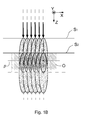
- Figure 5 depicts an experimental set-up and imagery pertaining to an exemplary embodiment of the current invention, as will now be explained in more detail.
- Figure 5A shows a beam geometry used to irradiate a surface S of a specimen.
- This figure depicts five different incident beam configurations, as follows [whereby notation “(A, T)” indicates “(azimuth angle, tilt angle)", as respectively measured clockwise from X (viewed parallel to Z) and w.r.t. XY plane]:
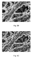
- Figures 5B and 5C show SEM imagery of a specimen of mouse brain tissue, imaged with the following tool settings and in accordance with the set-up shown in Figure 5A :
- Figure 5B shows the image obtained by considering beam B 1 only.
- Figure 5C shows the image obtained by combining all five beams and performing ICA-based image reconstruction in accordance with the present invention (see Embodiment 1 above, for example).
- Figure 6 depicts imagery pertaining to another exemplary embodiment of the current invention.
- the specimen in this case comprises rabbit lung tissue, imaged with the following tool settings:
- Figure 6A shows a conventional FIB-SEM image of the specimen, using a prior-art imaging technique.
Landscapes
- Chemical & Material Sciences (AREA)
- Analytical Chemistry (AREA)
- Physics & Mathematics (AREA)
- Engineering & Computer Science (AREA)
- Computer Vision & Pattern Recognition (AREA)
- General Physics & Mathematics (AREA)
- Optics & Photonics (AREA)
- General Engineering & Computer Science (AREA)
- Analysing Materials By The Use Of Radiation (AREA)
- Microscoopes, Condenser (AREA)
Abstract
Description
- The invention relates to a method of accumulating an image of a specimen using a scanning-type microscope, comprising the following steps:
- Directing a beam of radiation from a source through an illuminator so as to irradiate a surface S of the specimen;
- Using a detector to detect a flux of radiation emanating from the specimen in response to said irradiation;
- Causing said beam to follow a scan path relative to said surface;
- For each of a set of sample points in said scan path, recording an output Dn of the detector as a function of a value Pn of a selected measurement parameter P, thus compiling a measurement set M = {(Dn, Pn)}, where n is a member of an integer sequence;
- Using computer processing apparatus to automatically deconvolve the measurement set M and spatially resolve it so as to produce reconstructed imagery of the specimen.
- The invention also relates to a scanning-type microscope in which such a method can be performed.
- Charged-particle microscopy is a well-known and increasingly important technique for imaging microscopic objects, particularly in the form of electron microscopy. Historically, the basic genus of electron microscope has undergone evolution into a number of well-known apparatus species, such as the Transmission Electron Microscope (TEM), Scanning Electron Microscope (SEM), and Scanning Transmission Electron Microscope (STEM), and also into various sub-species, such as so-called "dual-beam" tools (e.g. a FIB-SEM), which additionally employ a "machining" Focused Ion Beam (FIB), allowing supportive activities such as ion-beam milling or Ion-Beam-Induced Deposition (IBID), for example. More specifically:
- In a SEM, irradiation of a specimen by a scanning electron beam precipitates emanation of "auxiliary" radiation from the specimen, in the form of secondary electrons, backscattered electrons, X-rays and photoluminescence (infrared, visible and/or ultraviolet photons), for example; one or more components of this flux of emanating radiation is/are then detected and used for image accumulation purposes.
- In a TEM, the electron beam used to irradiate the specimen is chosen to be of a high-enough energy to penetrate the specimen (which, to this end, will generally be thinner than in the case of a SEM specimen); the flux of transmitted electrons emanating from the specimen can then be used to create an image. When such a TEM is operated in scanning mode (thus becoming a STEM), the image in question will be accumulated during a scanning motion of the irradiating electron beam.
More information on some of the topics elucidated here can, for example, be gleaned from the following Wikipedia links:- http://en.wikipedia.org/wiki/Electron microscope
- http://en.wikipedia.org/wiki/Scanning electron microscope
- http://en.wikipedia.org/wiki/Transmission electron microscopy
- http://en.wikipedia.org/wiki/Scanning transmission electron microscopy
- http://en.wikipedia.org/wiki/Scanning Helium Ion Microscope
- W.H. Escovitz, T.R. Fox and R. Levi-Setti, Scanning Transmission Ion Microscope with a Field Ion Source, Proc. Nat. Acad. Sci. USA 72(5), pp 1826-1828 (1975).
- Apart from using charged particles as irradiating beam, it is also possible to perform scanning microscopy using a photon beam. An example of such a technique is so-called confocal microscopy, in which scanning irradiation by a point source of photons stimulates localized emanation of fluorescence radiation from the specimen. A detector can be used to collect (part of) this flux of fluorescence radiation and accumulate an image on the basis thereof. More information on this topic can, for example, be gleaned from the following Wikipedia link:
- http://en.wikipedia.org/wiki/Confocal microscopy
- In all cases, a scanning-type microscope will comprise at least the following components:
- A radiation source, such as a Schottky source or ion gun in the case of a CPM, or a laser or lamp in the case of an optical microscope.
- An illuminator, which serves to manipulate a "raw" radiation beam from the source and perform upon it certain operations such as focusing, aberration mitigation, cropping (with an aperture), filtering, etc. It will generally comprise one or more (charged-particle) lenses, and may comprise other types of (particle-)optical component also. If desired, the illuminator can be provided with a deflector system that can be invoked to cause its output beam to perform a scanning motion across the specimen being investigated.
- A specimen holder, on which a specimen under investigation can be held and positioned (e.g. tilted, rotated). If desired, this holder can be moved so as to effect the desired scanning motion of the beam w.r.t. the specimen. In general, such a specimen holder will be connected to a positioning system such as a mechanical stage.
- A detector, which may be unitary or compound/distributed in nature, and which can take many different forms, depending on the radiation being detected. Examples include photomultipliers (including solid-state photomultipliers, SSPMs), photodiodes, CMOS detectors, CCD detectors, photovoltaic cells, etc., which may, for example, be used in conjunction with a scintillator film, for instance.
- Methods as set forth in the opening paragraph above have been extensively developed in recent years by the assignee of the current application (FEI Company, Hillsboro, Oregon, USA). In particular, the following notable publications deserve mention:
- (i)
US 8,232,523 /EP 2 383 768 B1 , in which P is a property of the (incoming) radiation beam - such as beam energy, beam convergence angle or beam focal depth - and spatial resolution (deconvolution) of M is performed using a statistical Blind Source Separation (BSS) algorithm. - (ii)
US 8,581,189 /EP 2 557 586 B1 , in which P is again a property of the (incoming) radiation beam - such as beam energy, beam convergence angle or beam focal depth - and deconvolution of M is performed using a generalized three-dimensional reconstruction technique, e.g. on the basis of a Bayesian statistical approach. - (iii)
US 8,586,921 /EP 2 557 587 A2 , in which P is a property of the (emanating) radiation flux - specifically emission angle (e.g. of emitted secondary electrons) - and deconvolution of M is again conducted using a general volumetric reconstruction algorithm. - (iv)
US 8,704,176 /EP 2 648 208 A2 , in which P is again a property of the (emanating) radiation flux - specifically energy of emitted electrons - and deconvolution of M is once more achieved using three-dimensional reconstructive mathematics. - In deconvolving M, one can, for example, spatially resolve it into a result set R = {(Vk, Lk)}, in which a spatial variable V demonstrates a value Vk at an associated discrete depth level Lk referenced to the surface S, k being a member of an integer sequence, and spatial variable V representing a physical property of the specimen as a function of position in its bulk, e.g. contrast, intensity, density variation, atomic weight, staining concentration, electron yield/X-ray yield, etc., all of which are directly or indirectly determined by physical characteristics of (the material of) the specimen, and on the basis of which it is possible to construct an entity such as an image, map or spectrum, for example. In this way, one converts an inherently degenerate signal from the specimen into a depth-referenced image stack. A general way of solving this deconvolution problem is (for example) to:
- Define a Point Spread Function (PSF) that, for each value of n, has a kernel value Kn representing a behavior of said (incoming) beam of radiation in a bulk of the specimen as perceived by the detector for measurement parameter value Pn.
- Define an imaging quantity that, for each value of n, has a value Qn that is a multidimensional convolution of Kn and V, such that Qn = Kn * V;
- For each value of n, computationally determine a minimum divergence

- The above-mentioned techniques have produced a revolution in computational electron microscopy, allowing detailed SEM tomography to be performed as never before. Whereas the examples given above specifically involve the use of charged particles (such as electrons) in the irradiating beam, the basic principles involved can also be exploited in scanning-type optical microscopes, in which the irradiating beam comprises photons.
- Although techniques such as those set forth above produce satisfactory results, the current inventors have worked extensively to improve them even further. The results of this endeavor are the subject of the current application.
- It is an object of the invention to provide an improved method of the type set forth in the opening paragraph above. In particular, it is an object of the invention that such a method should offer greater imaging resolution than presently provided by methods of this kind.
- These and other objects are achieved in a method as set forth in the opening paragraph, characterized in that, considered at a given point pi within the specimen, the method comprises the following steps:
- In a first probing session, employing a first beam configuration B1 to irradiate the point pi with an associated first Point Spread Function F1, whereby said beam configuration is different to said measurement parameter;
- In at least a second probing session, employing a second beam configuration B2 to irradiate the point pi with an associated second Point Spread Function F2, whereby:
- ▪ F2 overlaps partially with F1 in a common overlap zone Oi in which point pi is located;
- ▪ F1 and F2 have respective non-overlapping zones F1' and F2' outside of Oi,
- Using a Source Separation algorithm in said computer processing apparatus to perform image reconstruction in said overlap zone Oi considered separately from said non-overlapping zones F1' and F2'.
- The crux of the current invention can be set forth in terms of mathematical considerations (see Embodiments below), but it can also be explained on the basis of a simplified physical elucidation. Basically, the inventive approach is ensuring that the point pi of the specimen located in overlap zone Oi will be subjected to (at least) two different regions/portions/aspects of the functional form f PSF of a PSF (which serves to describe physical interaction between the beam and the specimen). In this way, the technique of the current invention causes point pi (and the rest of zone Oi) to be "probed" by, for example:
- A "deeper region" of f PSF during the first probing session and an "shallower region" of f PSF during the second probing session; or
- A "left portion" of f PSF during the first probing session, and a "right portion" of f PSF during the second probing session,
- Since the overlap zone Oi is, by definition, smaller than the individual PSFs contributing to it, the inventive approach provides a finer-scale spatial resolution than "raw" prior-art techniques such as those set forth above. The present invention may thus be regarded as producing a super-resolution imaging result.
- The invention concentrates on common components of the overlapping PSFs in isolation from uncommon components, thus cutting out "dead wood" from the spatial resolution procedure.
- Since overlap zone Oi is inspected in multiple probing sessions, signal-to-noise ratio is inevitably improved.
- Each probing of Oi by a different region/portion of f PSF can be regarded as a means to establish a further member of a set of simultaneous equations describing Oi; the more simultaneous equations that one obtains, the more defined the solution space becomes.
- Independent Component Analysis (ICA), which is a technique that allows a multivariate signal to be separated into additive sub-components;
- Principal Component Analysis (PCA);
- Non-negative Matrix Factorization (NNMF),
- http://en.wikipedia.org/wiki/Independent component analysis
- The abovementioned patents
US 8,232,523 /EP 2 383 768 B1 . - [1] P. Comon and C. Jutten, Handbook of Blind Source Separation: Independent Component Analysis and Applications, Academic Press (2010).
- [2] A. Hyvärinen and E. Oja, Independent Component Analysis: Algorithms and Applications, Neural Networks, 13(4-5):411-430 (2000).
- [3] H. Lantéri, M. Roche, C. Aime, "Penalized maximum likelihood image restoration with positivity constraints: multiplicative algorithms, Inverse Problems," vol. 18, pp. 1397-1419 (2002).
- [4] I.T. Jolliffe, Principal Component Analysis, Series: Springer Series in Statistics XXIX, 2nd ed., Springer, NY (2002).
- In the context of this recitation and the further elucidation below, the following points should be borne in mind:
- (a) The abovementioned first and second probing sessions may, if desired, be supplemented by further probing sessions at point pi, thus leading to accumulation of a general set F={F1, F2, F3,..., Fj,...} of partially overlapping PSFs.
- (b) The inventive procedure at a given point pi can be repeated at a whole train p = {pi} of (successive) points along (below) the scan path. The associated overlap zones Oi will then effectively "merge" into a larger tract O={Oi}, e.g. in the form of a particular (sub-surface) stratum/volume in the specimen (see
Figures 1B and2B , for example). As explained above, "standard" spatial resolution can then be realized outside of O, but the current invention allows augmented spatial resolution to be achieved within O. - (c) In respect of the preceding item, one has, for example, the freedom to:
- (I) Deploy a full set F at point pi, and then repeat this procedure at each subsequent point in p ("full F before each step in p"); or
- (II) Deploy PSF Fj at each point in p, and then repeat this procedure for each subsequent PSF in F ("full p before each step in F").
- (d) The various probing sessions at point pi may, in principle, be performed serially or concurrently, whereby:
- In the former case (serial probing), point pi is first irradiated by a first beam having beam configuration B1, and is thereafter irradiated by a second beam having beam configuration B2, etc.
- In the latter case (concurrent probing), multiple beams are used to simultaneously
- irradiate point pi, at a range of (co-existing) mutually different beam configurations. The skilled artisan will readily understand these points.
- It should be explicitly noted that the present invention is fundamentally different in nature to the inventions set forth in patent documents (i)-(iv) above. In documents (i)-(iv), the measurement parameter P is varied as a way of obtaining (convoluted) imaging information from a series of (successive) depth layers within a specimen, i.e. adjustment of parameter P is regarded as a tool for probing deeper and deeper into the specimen. On the other hand, in the present invention, variation of parameter P is effectively a tool to tailor the size/shape of a "higher-order" (overlapping) PSF portion (Oi) - at a given position within a specimen - so as to be able to perform super-resolution image reconstruction in an area smaller than the footprint of a probing beam at said position. Lateral scanning motion of the probing beam can be exploited to extend said position into a layer (which could be surfacial or sub-surface) but, in its most fundamental form, the invention does not intrinsically yield bulk/volume imaging throughout different depths of the specimen (though such depth-resolved information could ultimately be obtained by using the extended invention on a (stacked) layer-by-layer basis).
- In a particular embodiment of the present invention, the following specific aspects apply:
- Said surface is defined to extend parallel to an XY-plane of a Cartesian coordinate system XYZ
- Said beam configuration is chosen to be a Z-position of a point of entry of the beam into the specimen;
- Between said first and second probing sessions, a physical slicing procedure is used to remove a layer of material of thickness L from an initial surface S1, thereby exposing a new surface S2;
- Point Spread Functions F2 and F1 are displaced relative to one another in said Z-direction by an amount L.
- Consider pi in the specimen to be located at a Z-distance L + z below S1, where z is some positive increment.
- In the first probing session, the incoming radiation beam B1 will impinge on S1 and produce a PSF F1 that extends down into the specimen from S1; point pi will then be located at a Z-distance L + z into this PSF F1.
- A physical slicing procedure (such as ion milling, microtome cutting, etching, etc.) is now used to remove a layer of thickness L from old surface S1, thereby exposing a fresh surface S2.
- In the second probing session, the incoming radiation beam B2 will impinge on S2 and produce a PSF F2 that extends down into the specimen from S2; point pi will then be located at a Z-distance z into this PSF F2. The PSFs F1 and F2 demonstrate a partial overlap zone Oi. Beams B1 and B2 have a common propagation axis b12, which extends parallel to the Z-direction.
- The PSFs F1 and F2 can have (approximately) the same functional form f PSF (e.g. an ovaloid, which starts with a narrow neck at the point of impingement of the beam, widens as one progresses into the specimen (lateral spread) and then tapers again with increasing extinction), but the overlap zone Oi containing pi will be subjected to a different Z-region of each. This fact allows an SS algorithm (such as ICA) to be used in performing detector signal deconvolution within zone Oi, resulting in augmented spatial resolution in this zone (compared to the prior art).
- As set forth in item (b) above, this effect need not be limited to just the zone Oi in which point pi is located; instead, if lateral scanning is performed during the first and second probing sessions, then zone Oi will be just one component of a merged tract (e.g. stratum/volume) O, located below S2, for which the current invention can realize improved spatial resolution. See, for example,
Figure 1B in this regard. - If desired, the procedure set forth above can be repeated in further iterations, whereby one progressively ventures deeper and deeper into the specimen, thus creating a stack of sub-surface tracts/strata O in which improved spatial resolution can be obtained. Such a scenario is, for example, illustrated in
Figure 1C . - The skilled artisan will understand that, in the current situation, approach (I) above cannot be employed, since there is an irreversible, destructive step (layer removal) between probing sessions; instead, approach (II) may be employed. In this context, it should be noted that:
- ▪ A whole measurement set 1 M can be obtained for PSF F1 (at each point pi in p), by varying a measurement parameter 1P and recording the attendant detector output.
- ▪ Similarly, a whole measurement set 2 M can be obtained for PSF F2 (at each point pi in p), by varying a measurement parameter 2P and recording the attendant detector output, whereby 2P and 1P may be the same or different.
- ▪ Each of these measurement sets 1 M, 2 M separately allows a spatially resolved image of (part of) the specimen to be generated; however, using the current inventive insights, a higher-resolution image may be obtained for the above-mentioned overlap tract O.
- In an alternative embodiment of the current invention, the following specific aspects apply:
- Said beam configuration is chosen to be an angle of the beam relative to the surface S (most generally considered in three dimensions);
- Between said first and second probing sessions, said angle of the beam is adjusted.
- Point Spread Functions F2 and F1 are angled relative to one another.
- Define a tilt angle T (declination / pitch) w.r.t. the surface S.
- In the first probing session, the incoming radiation beam B1 impinges on S at tilt T1, and produces a PSF F1 that extends into the specimen along propagation axis b1 and that intersects sub-surface point pi. If T1 ≠ 90°, then such impingement/extension will be oblique (otherwise it will be normal/perpendicular).
- In the second probing session, the incoming radiation beam B2 impinges on S at a different tilt T2, producing a PSF F2 that extends into the specimen along propagation axis b2 at a different slope, and again intersects point pi.
- Since T2 ≠ T1, point pi will experience different regions/aspects of PSFs F1 and F2 as measured along their respective propagation axes b1, b2. This fact allows an SS algorithm (such as ICA) to be used in performing detector signal deconvolution within zone Oi, resulting in augmented spatial resolution in this zone (compared to the prior art).
- Once again, as set forth in item (b) above, this effect need not be limited to just the zone Oi in which point pi is located; instead, if lateral scanning is performed during the first and second probing sessions, then zone Oi will be just one component of a merged tract (e.g. stratum/volume) O, located below S, for which the current invention can realize improved spatial resolution. See, for example,
Figure 2B in this regard. - Care should be taken not to confuse the "variable beam angle" embodiment of the previous paragraph with known - and very different - techniques such as so-called "micro-rotation". The technique of micro-rotation can be regarded as being an angular version of so-called confocal imaging, which is linear in nature. In confocal imaging, a focal plane is linearly displaced in (incremental) steps through a specimen, whereas, in micro-rotation, a sample is angularly rotated through a focal plane; in both cases, the intention is to "sweep" the focal plane (either linearly or angularly) through an extended volume of the specimen. In contrast, in the inventive embodiment of the previous paragraph, the purpose of beam tilt is to create a localized overlap zone (of adjustable size/shape/location) between different PSFs, for the purpose of defining a confined region in which super-resolution image reconstruction is to occur.
- In a further embodiment of the current invention, the following specific aspects apply:
- Said beam configuration is selected to be a species of particle in said beam;
- Point Spread Functions F2 and F1 are mutually different as regards at least one of size and shape.
- Consider the term "species" as here employed to refer to characteristics such as electrically charged or uncharged, sign of electrical charge, relatively heavy or light, relatively long- or short-wavelength, etc. In this context, particles such as electrons, protons, relatively light ions (e.g. He ions), relatively heavy ions (e.g. Ga ions), photons, soft or hard X-rays, etc., are considered to be different species of particle.
- Such different species of particle will generally demonstrate different interactions with a given specimen, with associated differences in the shape and/or size of the attendant PSF.
- In the first probing session, the incoming radiation beam B1 comprises a first species of particle. When this beam B1 impinges on S, it produces - for example - a PSF F1 that extends to a relatively deep level into the specimen, but with relatively little lateral spread. This PSF F1 intersects point pi.
- In the second probing session, the incoming radiation beam B2 comprises a second species of particle. When this beam B2 impinges on S, it produces - for example - a PSF F2 that extends to a relatively shallow level into the specimen, but with greater lateral spread than in the case of beam B1. This PSF F2 also intersects point pi.
- Since PSFs F2 and F1 differ in size and/or shape, point pi will experience different regions/portions/aspects of each. This fact allows an SS algorithm to be used in performing detector signal deconvolution within zone Oi, resulting in augmented spatial resolution in this zone (compared to the prior art).
- Once again, as set forth in item (b) above, this effect need not be limited to just the zone Oi in which point pi is located; instead, if lateral scanning is performed during the first and second probing sessions, then zone Oi will be just one component of a merged tract (e.g. stratum/volume) O, located below S, for which the current invention can realize improved spatial resolution. See, for example,
Figure 3B in this regard. - After the situation depicted in
Figure 2B has been enacted, a physical slicing procedure can be used to remove a layer of material of thickness L from the specimen, thereby exposing a new surface (refer toFigure 1A ); the situation shown inFigure 2B can then be repeated on this newly exposed surface. A similar statement applies to the situation depicted inFigure 3B , for example. - The beams of
Figures 1A and3A may, if desired, be shot obliquely into the specimen rather than normally. - The invention will now be elucidated in more detail on the basis of exemplary embodiments and the accompanying schematic drawings, in which:
-
Figure 1 renders a cross-sectional view of a specimen that is being imaged according to a particular embodiment of the current invention. -
Figure 2 renders a cross-sectional view of a specimen that is being imaged according to another embodiment of the current invention. -
Figure 3 renders a cross-sectional view of a specimen that is being imaged according to yet another embodiment of the current invention. -
Figure 4 renders a cross-sectional view of an embodiment of a scanning-type microscope according to the present invention. -
Figure 5 depicts an experimental set-up and imagery pertaining to an exemplary embodiment of the current invention. -
Figure 6 depicts imagery pertaining to another exemplary embodiment of the current invention. - In the Figures, where pertinent, corresponding parts are indicated using corresponding reference symbols.
-
Figure 2A renders a cross-sectional view of a specimen that is being imaged according to given embodiment of the current invention. As already alluded to above, this Figure illustrates the following: - A first incoming radiation beam B1 that impinges on specimen surface S at tilt T1, and produces a PSF F1 that extends into the specimen along propagation axis b1, and that intersects sub-surface point pi.
- A second incoming radiation beam B2 that impinges on S at a different tilt T2, producing a PSF F2 that extends into the specimen along propagation axis b2 at a different slope, and again intersects point pi.
- Since T2 ≠ T1, point pi experiences different regions/aspects of PSFs F1 and F2 as measured along their respective propagation axes b1, b2. This fact allows an SS algorithm to be used in performing detector signal deconvolution within zone Oi, resulting in augmented spatial resolution in this zone. This will now be explained in more detail.
- When scanning the surface S of the specimen, one collects the detector output for each scan position, thus forming an "image" D. In the reconstruction scheme discussed here, one is acquiring images using a scanning beam oriented at respective 'azimuthal' (yaw) and 'tilt' (pitch, declination) angles (A, T) with respect to a reference frame (XYZ) whose Z-axis is normal to the surface S (XY plane) of the specimen (azimuthal angle A not depicted in
Figure 2 ). These images are here labeled DA,T. For simplicity, the following will limit itself to a situation wherein the azimuthal angles are separated by 180° (opposite directions). Two images are acquired (either serially or concurrently) at respective tilt angles T 1 and T 2 (a special case is T 1 = T and T 2 = -T), and these two images are respectively labeled D T1 and D T2 . For D T1 , the collection of detected signals at the visited scan locations is obtained from the collection of volumes covered by the PSF F 1. In the case of D T2 , the imaging process uses the PSF F 2. Obtaining a sharper image, coming from a set of less extended volumes in the specimen, can be achieved by 'shifting' one of the tilt images (for example DT1 ) by a certain number of "pixels" with respect to the other image. The amount of such shift will determine the subsurface location of a volume of intersection of the two PSFs F 1 and F 2, which intersection volume is labeled O i inFig. 2A . When there is no X-shift, said intersection volume O i lies immediately underneath the surface S. Extracting the signal coming exclusively from the collection of intersection volumes O i (for all scan locations) can be done using statistical source separation techniques such as Independent Component Analysis (ICA), for example. - For further explanation, one can define:
- □
-

- □


i corresponding to these virtual PSFs (volumes). Such virtual images will have lower statistical correlation than the original images. In the case of linear imaging models, one obtains: - where the criterion J(.∥.) is a statistical similarity measure between model and observations. Typical choices for J(.∥.) are the least squares measure for signals with Gaussian noise, or the Kullback-Leibler divergence for Poisson noise, for instance. Other divergences can be used as well: see, for example, the above-referenced
US 8,581,189 (item (ii) above), col. 5, line 33 - col. 6, line 33. - For better convergence, and to restrict the space of solutions, a regularization term can be added to (7), yielding:

- The regularization term R(W, D', θ) represents prior-knowledge constraints, and may depend on the decomposition variables (W,D') as well as on other parameters θ that emerge from simulations and measurements. For example, one could use:
- Parameters for an analytical model of a scanning beam's interaction with a specific class of materials (such as plastic-embedded heavy-particle-stained specimens, for example);
- Parameters constraining the geometry and contrast of the reconstructed structures: for example, synaptic vesicles are, on average, spherical and have a diameter of approximately 39.5 nm,
- One can see that, in problems (7) and (8), optimizing with respect to W boils down to optimizing with respect to α. Ultimately, as mentioned earlier, the most important component to recover is DO
i , which is the image corresponding to the smaller "intersection volume". - What follows is an example of solving for (7) in the case of a least squares measure. In this case, one solves for:

which is typically regularized using non-negativity conditions, as indicated in (9) by the stipulations W ≥ 0, D' ≥ 0 . This problem can be approached by alternating two minimization steps, with respect to W and D'. In the first step, one computes a derivative with respect to W and sets it to zero:
From which one obtains:
Differentiating the least squares criterion with respect to D' and setting to zero leads to:
- In the ALS algorithm, the two steps (11) and (12) are alternated until a suitable convergence criterion is achieved. The aforementioned non-negativity constraints are imposed, for example, by setting negative values to zero, or by employing a so-called active set technique, as described (for example) in references [1] and [2] above.
- In this case, one minimizes the following so-called Generalized Kullback-Leibler (KL) divergence:


where the indices ij, and k are used to refer to elements of the different matrices, and where left hand quantities are values being computed at iteration t+1, and right hand quantities are values obtained at iteration t. -
Figure 2B has already been discussed in the general Description above, and requires no further elucidation here. -
Figure 1A renders a cross-sectional view of a specimen that is being imaged according to another embodiment of the current invention. As already alluded to above, this Figure schematically depicts the following: - A first incoming radiation beam B1 that impinges on (original) specimen surface S1 and produces a PSF F1 that extends down into the specimen from S1; point pi is located at a Z-distance L + z into this PSF F1.
- A second incoming radiation beam B2 that impinges on (newly exposed) specimen surface on S2 and produces a PSF F2 that extends down into the specimen from S2; point pi is located at a Z-distance z into this PSF F2. This new surface S2 was created by utilizing a physical slicing procedure (such as ion milling, microtome cutting, etching, etc.) to remove a layer of thickness L from old surface S1, thereby exposing a fresh surface S2.
- The PSFs F1 and F2 demonstrate a partial overlap zone Oi. Beams B1 and B2 have a common propagation axis b12, which extends parallel to the Z-direction. The overlap zone Oi containing pi will be subjected to a different Z-region of each PSF. This fact allows (for example) ICA to be used in performing detector signal deconvolution within zone Oi, resulting in augmented spatial resolution in this zone. This will now be explained in more detail.
- In the case of reconstructions from multiple imaging sessions at different surfaces, one can follow the same reasoning as in Embodiment 1 above and define three PSFs:


Fig. 1A one can see that, in this case, the "virtual images"

i correspond to volumes stacked from the top to the bottom. Each of these "virtual" volumes will have less thickness than the two original ones, and hence should correspond to sharper images with fewer volume effects. If one defines the images obtained at surfaces S 1 and S 2 as D S1 and D S2 , respectively, one can derive the relationship between the observed and "virtual" images as follows:

If one accounts for a change in imaging conditions that introduces different "intensity" scaling α between the two sessions, one obtains:

which leads to the matrix representation:
with
- Using the same ICA techniques as described above, one can recover the three images corresponding to the three layers from top to bottom.
-
Figures 1B and1C have already been discussed in the general Description above, and require no further elucidation here. - It will be well within the ambit of the skilled artisan to extend the reconstruction techniques described above to more than two scans (probing sessions). For the multi-tilt case of Embodiment 1, for example, the different PSFs should in that case intersect in the same common ("pivot") region. The linearity of the imaging process will always result in decompositions represented by systems of equations similar to (5) and (20). Such systems can be solved using identical computational methods.
-
Figure 3A renders a cross-sectional view of a specimen that is being imaged according to yet another embodiment of the current invention. As already alluded to above, this Figure schematically depicts the following: - A first the incoming radiation beam B1, which comprises a first species of particle. When this beam B1 impinges on S, it produces a PSF F1 that extends to a relatively deep level into the specimen, but with relatively little lateral spread. This PSF F1 intersects point pi.
- A second incoming radiation beam B2, which comprises a second species of particle. When this beam B2 impinges on S, it produces a PSF F2 that extends to a relatively shallow level into the specimen, but with greater lateral spread than in the case of beam B1. This PSF F2 also intersects point pi.
- Since PSFs F2 and F1 differ in size and/or shape, point pi will experience different regions/portions/aspects of each. This fact allows (for example) ICA to be used in performing detector signal deconvolution within zone Oi, resulting in augmented spatial resolution in this zone.
- The reconstruction mathematics in this case are broadly similar to the general framework set forth in Embodiments 1 and 2 above. This particular situation is one in which the relative weighting factor α introduced above in equations (3) and (18) can play an important role, because of the (typical) dissimilarity between PSFs F1 and F2.
-
Figure 3B has already been discussed in the general Description above, and requires no further elucidation here. -
Figure 4 is a highly schematic depiction of an embodiment of a scanning-type microscope according to the present invention; more specifically, it shows an embodiment of a charged-particle microscope 400, which, in this case, is a SEM. Themicroscope 400 comprises a particle-optical column 402, which produces abeam 404 of input charged particles (in this case, an electron beam). The particle-optical column 402 is mounted on avacuum chamber 406, which comprises a specimen holder /stage 408 for holding aspecimen 410. Thevacuum chamber 406 is evacuated using vacuum pumps (not depicted). With the aid ofvoltage source 422, thespecimen holder 408, or at least thespecimen 410, may, if desired, be biased (floated) to an electrical potential with respect to ground. - The particle-
optical column 402 comprises an electron source 412 (such as a Schottky gun),lenses electron beam 404 onto thespecimen 410, and a deflection unit 418 (to perform beam steering / scanning of the beam 404). Theapparatus 400 further comprises a controller /computer processing apparatus 424 for controlling inter alia thedeflection unit 418,lenses detectors detectors display unit 426. In the current context,items - The
detectors specimen 410 in response to irradiation by theinput beam 404. In the apparatus depicted here, the following detector choices have been made: -
Detector 100 is a segmented electron detector. Such a detector can, for example, be used to investigate the angular dependence of a flux of output (secondary or backscattered) electrons emerging from thespecimen 410. -
Detector 420 is a boron-doped solid state detector that is used to detect (at least a portion of) a flux of output electrons emanating from thespecimen 410. - As here rendered, both
detectors - By scanning the
input beam 404 over thespecimen 410, output radiation - comprising, for example, a flux of X-rays, infrared/visible/ultraviolet light, secondary electrons and or backscattered (BS) electrons - emanates from thespecimen 410. As such output radiation is position-sensitive (due to said scanning motion), the information obtained from thedetectors detector 420 to be used to produce (for example) a BS electron image of (part of) thespecimen 410, which image is basically a map of an output ofdetector 420 as a function of scan-path position on thespecimen 410. - The signals from the
detectors controller 424, and displayed ondisplay unit 426. Such processing may include operations such as combining, integrating, subtracting, false colouring, edge enhancing, and other processing known to the skilled artisan. In addition, automated recognition processes (e.g. as used for particle analysis) may be included in such processing. - It should be noted that many refinements and alternatives of such a set-up will be known to the skilled artisan, including, but not limited to:
- The use of dual beams - for example an
electron beam 404 for imaging and an ion beam for machining (or, in some cases, imaging) thespecimen 410; - The use of a controlled environment at the specimen 410 - for example, maintaining a pressure of several mbar (as used in a so-called Environmental SEM) or by admitting gases, such as etching or precursor gases,
- In the specific context of the current invention, the controller 424 - and/or a dedicated separate processing unit (not shown) - can be invoked to perform the following actions in respect of a given point pi within the specimen 410:
- In a first probing session, employing a first beam configuration B1 to irradiate the point pi with an associated first Point Spread Function F1, whereby said beam configuration is different to said measurement parameter;
- In at least a second probing session, employing a second beam configuration B2 to irradiate the point pi with an associated second Point Spread Function F2, whereby:
- ▪ F2 overlaps partially with F1 in a common overlap zone Oi in which point pi is located;
- ▪ F1 and F2 have respective non-overlapping zones F1' and F2' outside of Oi,
- Using a Source Separation algorithm in said computer processing apparatus to perform image reconstruction in said overlap zone Oi considered separately from said non-overlapping zones F1' and F2'.
- Although the scanning-type microscope shown in
Figure 4 is a SEM, it could, in the context of the current invention, just as validly be a STEM, FIB-SEM or confocal microscope, for example. -
Figure 5 depicts an experimental set-up and imagery pertaining to an exemplary embodiment of the current invention, as will now be explained in more detail. -
Figure 5A shows a beam geometry used to irradiate a surface S of a specimen. This figure depicts five different incident beam configurations, as follows [whereby notation "(A, T)" indicates "(azimuth angle, tilt angle)", as respectively measured clockwise from X (viewed parallel to Z) and w.r.t. XY plane]: - Beam B1: normal incidence.
- Beam B2: angled incidence at (A, T) = (180°, 60°).
- Beam B3: angled incidence at (A, T) = (270°, 60°).
- Beam B4: angled incidence at (A, T) = (0°, 60°).
- Beam B5: angled incidence at (A, T) = (90°, 60°).
-
Figures 5B and 5C show SEM imagery of a specimen of mouse brain tissue, imaged with the following tool settings and in accordance with the set-up shown inFigure 5A : - Acceleration voltage: 2kV.
- Beam current: ca. 400pA.
- Depicted Field of View: 1.5µm x 1.1µm.
- Resolution: 4nm/pixel.
- Detected flux species: Backscattered electrons.
-
Figure 5B shows the image obtained by considering beam B1 only. -
Figure 5C shows the image obtained by combining all five beams and performing ICA-based image reconstruction in accordance with the present invention (see Embodiment 1 above, for example). - It is immediately clear that the detail/resolution in
Figure 5C (current invention) is very superior to that ofFigure 5B (prior art). -
Figure 6 depicts imagery pertaining to another exemplary embodiment of the current invention. The specimen in this case comprises rabbit lung tissue, imaged with the following tool settings: - Acceleration voltage: 2kV.
- Beam current: ca. 400pA.
- Depicted Field of View: 1.05µm x 0.98µm.
- Resolution: 4nm/pixel.
- Detected flux species: Backscattered electrons.
-
Figure 6A shows a conventional FIB-SEM image of the specimen, using a prior-art imaging technique. -
Figure 6B shows the image obtained by performing ICA-based image reconstruction in accordance with the present invention, using an "irradiate-slice-irradiate" approach such as that set forth in Embodiment 2 /Figure 1A above, for example (the FIB functionality of the employed tool being used to perform ion milling on the specimen between irradiation runs, removing a layer of thickness L = ca. 4nm). - It is again clear that that the image in
Figure 6B (current invention) is crisper than that ofFigure 6A (prior art).


This model applies in the case where the beam parameters (such as current/particle flux or acceleration voltage) are identical for the two scans (probing sessions). If one of the beams has a different "intensity" (i.e. greater or lesser importance / influence / "gravity"), a relative weight α given to the intersection region will change from a value of 1.0, resulting in the more general expressions:


or, in matrix form:

with:

The problem to be solved here consists of recovering the virtual images


Find the pair


Claims (9)
- A method of accumulating an image of a specimen using a scanning-type microscope, comprising the following steps:- Directing a beam of radiation from a source through an illuminator so as to irradiate a surface S of the specimen;- Using a detector to detect a flux of radiation emanating from the specimen in response to said irradiation;- Causing said beam to follow a scan path relative to said surface;- For each of a set of sample points in said scan path, recording an output Dn of the detector as a function of a value Pn of a selected measurement parameter P, thus compiling a measurement set M = {(Dn, Pn)}, where n is a member of an integer sequence;- Using computer processing apparatus to automatically deconvolve the measurement set M and spatially resolve it so as to produce reconstructed imagery of the specimen, characterized in that, considered at a given point pi within the specimen, the method comprises the following steps:- In a first probing session, employing a first beam configuration B1 to irradiate the point pi with an associated first Point Spread Function F1, whereby said beam configuration is different to said measurement parameter;- In at least a second probing session, employing a second beam configuration B2 to irradiate the point pi with an associated second Point Spread Function F2, whereby:▪ F2 overlaps partially with F1 in a common overlap zone Oi in which point pi is located;▪ F1 and F2 have respective non-overlapping zones F1' and F2' outside of Oi,- Using a Source Separation algorithm in said computer processing apparatus to perform image reconstruction in said overlap zone Oi considered separately from said non-overlapping zones F1' and F2'.
- A method according to claim 1, wherein- Said surface is defined to extend parallel to an XY-plane of a Cartesian coordinate system XYZ;- Said beam configuration is chosen to be a Z-position of a point of entry of the beam into the specimen;- Between said first and second probing sessions, a physical slicing procedure is used to remove a layer of material of thickness L from an initial surface S1, thereby exposing a new surface S2.- Point Spread Functions F2 and F1 are displaced relative to one another in said Z-direction by an amount L.
- A method according to claim 1 or 2, wherein:- Said beam configuration is chosen to be an angle of the beam relative to the surface S;- Between said first and second probing sessions, said angle of the beam is adjusted.- Point Spread Functions F2 and F1 are angled relative to one another.
- A method according to any of claims 1-3, wherein:- Said beam configuration is selected to be a species of particle in said beam;- Point Spread Functions F2 and F1 are mutually different as regards at least one of size and shape.
- A method according to any of claims 1-4, wherein said measurement parameter is selected from the group comprising:- An average landing energy of particles in said beam;- An average current of charged particles in said beam;- An emission angle of particles in said flux;- An emission energy of particles in said flux,and combinations hereof.
- A method according to any preceding claim, wherein said flux of radiation emanating from the specimen comprises at least one species selected from the group comprising backscatter electrons, secondary electrons, X-rays, infrared light, visible light, ultraviolet light, and combinations hereof.
- A method according to any preceding claim, wherein said deconvolution and spatial resolution of the measurement set M are performed by minimizing a statistical divergence between a detection model and the measurement set M, assumed subject to at least one of Poisson noise and Gaussian noise, whilst applying constraints to said model.
- A method according to any of any preceding claim, wherein said Source Separation algorithm is selected from the group comprising Independent Component Analysis, Principal Component Analysis, Non-Negative Matrix Factorization, and combinations and hybrids hereof.
- A scanning-type microscope comprising:- A specimen holder, for holding a specimen;- A source, for producing a beam of radiation;- An illuminator, for directing said beam so as to irradiate said specimen;- A detector, for detecting a flux of radiation emanating from the specimen in response to said irradiation;- Scanning means, for causing said beam to traverse a scan path relative to a surface of the specimen;- A controller, for:□ recording an output Dn of the detector as a function of a value Pn of a selected measurement parameter P, for each of a set of sample points in said scan path, thus compiling a measurement set M = {(Dn, Pn)}, where n is a member of an integer sequence;□ automatically deconvolving the measurement set M and spatially resolving it so as toproduce reconstructed imagery of the specimen,
characterized in that, in respect of a given point pi within the specimen, said controller can be invoked to execute the following steps:- In a first probing session, employ a first beam configuration B1 to irradiate the point pi with an associated first Point Spread Function F1, whereby said beam configuration is different to said measurement parameter;- In at least a second probing session, employ a second beam configuration B2 to irradiate the point pi with an associated second Point Spread Function F2, whereby:▪ F2 overlaps partially with F1 in a common overlap zone Oi in which point pi is located;▪ F1 and F2 have respective non-overlapping zones F1' and F2' outside of Oi,- Use a Source Separation algorithm to perform image reconstruction in said overlap zone Oi considered separately from said non-overlapping zones F1' and F2'.
Priority Applications (1)
| Application Number | Priority Date | Filing Date | Title |
|---|---|---|---|
| EP15174190.7A EP2963673B1 (en) | 2014-06-30 | 2015-06-29 | Computational scanning microscopy with improved resolution |
Applications Claiming Priority (2)
| Application Number | Priority Date | Filing Date | Title |
|---|---|---|---|
| EP14174903.6A EP2963672A1 (en) | 2014-06-30 | 2014-06-30 | Computational scanning microscopy with improved resolution |
| EP15174190.7A EP2963673B1 (en) | 2014-06-30 | 2015-06-29 | Computational scanning microscopy with improved resolution |
Publications (2)
| Publication Number | Publication Date |
|---|---|
| EP2963673A1 true EP2963673A1 (en) | 2016-01-06 |
| EP2963673B1 EP2963673B1 (en) | 2019-11-13 |
Family
ID=51059308
Family Applications (2)
| Application Number | Title | Priority Date | Filing Date |
|---|---|---|---|
| EP14174903.6A Withdrawn EP2963672A1 (en) | 2014-06-30 | 2014-06-30 | Computational scanning microscopy with improved resolution |
| EP15174190.7A Active EP2963673B1 (en) | 2014-06-30 | 2015-06-29 | Computational scanning microscopy with improved resolution |
Family Applications Before (1)
| Application Number | Title | Priority Date | Filing Date |
|---|---|---|---|
| EP14174903.6A Withdrawn EP2963672A1 (en) | 2014-06-30 | 2014-06-30 | Computational scanning microscopy with improved resolution |
Country Status (4)
| Country | Link |
|---|---|
| US (1) | US9478393B2 (en) |
| EP (2) | EP2963672A1 (en) |
| JP (2) | JP2016015315A (en) |
| CN (1) | CN105280463B (en) |
Cited By (3)
| Publication number | Priority date | Publication date | Assignee | Title |
|---|---|---|---|---|
| EP3499459A1 (en) | 2017-12-18 | 2019-06-19 | FEI Company | Method, device and system for remote deep learning for microscopic image reconstruction and segmentation |
| EP3505905A1 (en) | 2017-12-28 | 2019-07-03 | FEI Company | Method, device and system for the treatment of biological cryogenic samples by plasma focused ion beams |
| US11042017B2 (en) | 2016-03-14 | 2021-06-22 | Olympus Corporation | Point-spread-function measurement device and measurement method, image acquisition apparatus, and image acquisition method |
Families Citing this family (25)
| Publication number | Priority date | Publication date | Assignee | Title |
|---|---|---|---|---|
| US9627175B2 (en) * | 2014-10-17 | 2017-04-18 | Jeol Ltd. | Electron microscope and elemental mapping image generation method |
| EP3104155A1 (en) | 2015-06-09 | 2016-12-14 | FEI Company | Method of analyzing surface modification of a specimen in a charged-particle microscope |
| EP3171163B1 (en) | 2015-11-18 | 2022-05-04 | FEI Company | X-ray imaging technique |
| US9952422B2 (en) * | 2016-01-14 | 2018-04-24 | University Of Vienna | Enhancing the resolution of three dimensional video images formed using a light field microscope |
| EP3240013B1 (en) * | 2016-04-26 | 2018-11-07 | FEI Company | Three-dimensional imaging in charged-particle microscopy |
| DE102016208689B4 (en) * | 2016-05-20 | 2018-07-26 | Carl Zeiss Microscopy Gmbh | A method of generating an image of an object and / or a representation of data about the object, and computer program product and particle beam apparatus for performing the method |
| CN110072462B (en) * | 2016-09-16 | 2022-05-24 | 国家医疗保健研究所 | Method for imaging a sample containing blood and related device |
| US10935779B2 (en) * | 2016-10-27 | 2021-03-02 | Scopio Labs Ltd. | Digital microscope which operates as a server |
| EP3538941B1 (en) | 2016-11-10 | 2025-04-23 | The Trustees of Columbia University in the City of New York | Rapid high-resolution imaging methods for large samples |
| JP6668278B2 (en) * | 2017-02-20 | 2020-03-18 | 株式会社日立ハイテク | Sample observation device and sample observation method |
| JP6811324B2 (en) * | 2017-07-05 | 2021-01-13 | 株式会社日立ハイテク | Charged particle beam device |
| SG11202000125TA (en) * | 2017-07-17 | 2020-02-27 | Univ Nanyang Tech | Apparatus and methods for imaging |
| MA44921B1 (en) * | 2017-07-22 | 2021-01-29 | Intelligent Virus Imaging Inc | Process for automated unsupervised ontological study of structural aspects in electron micrographs |
| US10811219B2 (en) * | 2018-08-07 | 2020-10-20 | Applied Materials Israel Ltd. | Method for evaluating a region of an object |
| KR20200030806A (en) | 2018-09-13 | 2020-03-23 | 삼성전자주식회사 | Non-transitory computer-readable medium comprising image conversion model based on artificial neural network and method of converting image of semiconductor wafer for monitoring semiconductor fabrication process |
| DE102019100184A1 (en) * | 2019-01-07 | 2020-07-09 | Carl Zeiss Microscopy Gmbh | High resolution scanning microscopy |
| EP3726206B1 (en) * | 2019-03-26 | 2022-11-02 | FEI Company | Methods and systems for inclusion analysis |
| WO2021130839A1 (en) * | 2019-12-24 | 2021-07-01 | 株式会社日立ハイテク | Defect inspecting system and defect inspecting method |
| CN112373016B (en) * | 2020-10-23 | 2023-02-17 | 杭州德迪智能科技有限公司 | Three-dimensional layered modeling method, device, electronic device and storage medium |
| JP2022135215A (en) * | 2021-03-05 | 2022-09-15 | 株式会社日立ハイテク | Learning method of learning device and image generation system |
| TWI783684B (en) | 2021-09-15 | 2022-11-11 | 國立成功大學 | Method of detecting magnetic distribution |
| EP4191637A1 (en) * | 2021-12-02 | 2023-06-07 | Max-Planck-Gesellschaft zur Förderung der Wissenschaften e.V. | Method for automatic focusing and astigmatism correction for an electron microscope |
| WO2023151946A1 (en) * | 2022-02-10 | 2023-08-17 | Carl Zeiss Smt Gmbh | Method to investigate a semiconductor sample layer by layer and investigation device to perform such method |
| US12495214B2 (en) | 2023-03-15 | 2025-12-09 | General Electric Company | Pulse illumination imaging of a target element |
| US12593131B2 (en) | 2023-09-05 | 2026-03-31 | General Electric Company | Velocity matching imaging of a target element |
Citations (3)
| Publication number | Priority date | Publication date | Assignee | Title |
|---|---|---|---|---|
| US20110266440A1 (en) * | 2010-04-29 | 2011-11-03 | Fei Company | SEM Imaging Method |
| EP2557587A2 (en) | 2011-08-10 | 2013-02-13 | Fei Company | Charged-particle microscope providing depth-resolved imagery |
| EP2648208A2 (en) | 2012-04-05 | 2013-10-09 | Fei Company | Charged-particle microscope providing depth-resolved imagery |
Family Cites Families (6)
| Publication number | Priority date | Publication date | Assignee | Title |
|---|---|---|---|---|
| WO2001085011A2 (en) * | 2000-05-11 | 2001-11-15 | Technion Research & Development Foundation Ltd. | Wavelet depulsing of ultrasound echo sequences |
| WO2002023247A1 (en) * | 2000-09-18 | 2002-03-21 | Vincent Lauer | Confocal optical scanning device |
| US20100224796A1 (en) * | 2005-09-09 | 2010-09-09 | Jerome Mertz | Imaging System Using Dynamic Speckle Illumination |
| US8031924B2 (en) * | 2007-11-30 | 2011-10-04 | General Electric Company | Methods and systems for removing autofluorescence from images |
| DE102010044013A1 (en) * | 2010-11-16 | 2012-05-16 | Carl Zeiss Microimaging Gmbh | Depth resolution enhanced microscopy |
| US8704176B2 (en) | 2011-08-10 | 2014-04-22 | Fei Company | Charged particle microscope providing depth-resolved imagery |
-
2014
- 2014-06-30 EP EP14174903.6A patent/EP2963672A1/en not_active Withdrawn
-
2015
- 2015-06-23 JP JP2015125288A patent/JP2016015315A/en active Pending
- 2015-06-26 US US14/752,570 patent/US9478393B2/en active Active
- 2015-06-29 EP EP15174190.7A patent/EP2963673B1/en active Active
- 2015-06-30 CN CN201510384825.2A patent/CN105280463B/en active Active
-
2017
- 2017-12-01 JP JP2017232132A patent/JP6333462B2/en active Active
Patent Citations (7)
| Publication number | Priority date | Publication date | Assignee | Title |
|---|---|---|---|---|
| US20110266440A1 (en) * | 2010-04-29 | 2011-11-03 | Fei Company | SEM Imaging Method |
| US8232523B2 (en) | 2010-04-29 | 2012-07-31 | Fei Company | SEM imaging method |
| EP2383768B1 (en) | 2010-04-29 | 2013-07-17 | FEI Company | SEM imaging method |
| EP2557587A2 (en) | 2011-08-10 | 2013-02-13 | Fei Company | Charged-particle microscope providing depth-resolved imagery |
| US8581189B2 (en) | 2011-08-10 | 2013-11-12 | Fei Company | Charged particle microscopy imaging method |
| EP2557586B1 (en) | 2011-08-10 | 2014-04-02 | Fei Company | Charged-particle microscopy imaging method |
| EP2648208A2 (en) | 2012-04-05 | 2013-10-09 | Fei Company | Charged-particle microscope providing depth-resolved imagery |
Non-Patent Citations (9)
| Title |
|---|
| A. HYVARINEN; E. OJA: "Independent Component Analysis: Algorithms and Applications", NEURAL NETWORKS, vol. 13, no. 4-5, 2000, pages 411 - 430, XP004213197, DOI: doi:10.1016/S0893-6080(00)00026-5 |
| H. LANTERI; M. ROCHE; C. AIME: "Penalized maximum likelihood image restoration with positivity constraints: multiplicative algorithms", INVERSE PROBLEMS, vol. 18, 2002, pages 1397 - 1419 |
| I.T. JOLLIFFE: "Principal Component Analysis", 2002, SPRINGER |
| P. COMON; C. JUTTEN: "Handbook of Blind Source Separation: Independent Component Analysis and Applications", 2010, ACADEMIC PRESS |
| RANJAN RAMACHANDRA AND NIELS DE JONGE: "Optimized Deconvolution for Maximum Axial Resolution in Three-Dimensional Aberration-Corrected Scanning Transmission Electron Microscopy", MICROSCOPY AND MICROANALYSIS, SPRINGER, NEW YORK, NY, US, vol. 18, no. 1, 1 February 2012 (2012-02-01), pages 218 - 228, XP001571654, ISSN: 1431-9276, [retrieved on 20111208], DOI: 10.1017/S1431927611012347 * |
| ROMAN SCHMIDT ET AL: "Spherical nanosized focal spot unravels the interior of cells", NATURE METHODS, vol. 5, no. 6, 1 June 2008 (2008-06-01), pages 539 - 544, XP055067550, ISSN: 1548-7091, DOI: 10.1038/nmeth.1214 * |
| TIM DAHMEN ET AL: "Combined Scanning Transmission Electron Microscopy Tilt- and Focal Series", MICROSCOPY AND MICROANALYSIS, SPRINGER, NEW YORK, NY, US, vol. 20, no. 2, 1 April 2014 (2014-04-01), pages 548 - 560, XP001589137, ISSN: 1431-9276, [retrieved on 20140219], DOI: 10.1017/S1431927614000075 * |
| W.H. ESCOVITZ; T.R. FOX; R. LEVI-SETTI: "Scanning Transmission Ion Microscope with a Field Ion Source", PROC. NAT. ACAD. SCI. USA, vol. 72, no. 5, 1975, pages 1826 - 1828, XP002402529, DOI: doi:10.1073/pnas.72.5.1826 |
| YONG YU ET AL: "A Bayesian 3D Volume Reconstruction for Confocal Micro-rotation Cell Imaging", 29 October 2007, MEDICAL IMAGE COMPUTING AND COMPUTER-ASSISTED INTERVENTION - MICCAI 2007; [LECTURE NOTES IN COMPUTER SCIENCE], SPRINGER BERLIN HEIDELBERG, BERLIN, HEIDELBERG, PAGE(S) 685 - 692, ISBN: 978-3-540-75758-0, XP019081865 * |
Cited By (4)
| Publication number | Priority date | Publication date | Assignee | Title |
|---|---|---|---|---|
| US11042017B2 (en) | 2016-03-14 | 2021-06-22 | Olympus Corporation | Point-spread-function measurement device and measurement method, image acquisition apparatus, and image acquisition method |
| EP3499459A1 (en) | 2017-12-18 | 2019-06-19 | FEI Company | Method, device and system for remote deep learning for microscopic image reconstruction and segmentation |
| US10903043B2 (en) | 2017-12-18 | 2021-01-26 | Fei Company | Method, device and system for remote deep learning for microscopic image reconstruction and segmentation |
| EP3505905A1 (en) | 2017-12-28 | 2019-07-03 | FEI Company | Method, device and system for the treatment of biological cryogenic samples by plasma focused ion beams |
Also Published As
| Publication number | Publication date |
|---|---|
| EP2963673B1 (en) | 2019-11-13 |
| JP6333462B2 (en) | 2018-05-30 |
| US9478393B2 (en) | 2016-10-25 |
| CN105280463A (en) | 2016-01-27 |
| EP2963672A1 (en) | 2016-01-06 |
| JP2016015315A (en) | 2016-01-28 |
| JP2018067551A (en) | 2018-04-26 |
| US20160013015A1 (en) | 2016-01-14 |
| CN105280463B (en) | 2018-06-22 |
Similar Documents
| Publication | Publication Date | Title |
|---|---|---|
| EP2963673B1 (en) | Computational scanning microscopy with improved resolution | |
| US10573488B2 (en) | Method of performing tomographic imaging in a charged-particle microscope | |
| US9711325B2 (en) | Charged-particle microscope providing depth-resolved imagery | |
| EP2557587B1 (en) | Charged-particle microscope providing depth-resolved imagery | |
| US8232523B2 (en) | SEM imaging method | |
| EP2958131B1 (en) | Mathematical image assembly in a scanning-type microscope | |
| EP2648208B1 (en) | Charged-particle microscope providing depth-resolved imagery | |
| CN107316793A (en) | Three-dimensional imaging in charged particle microscopy | |
| US12626884B2 (en) | Method and scanning transmission charged-particle microscope | |
| Bosch | Boughorbel et a1. |
Legal Events
| Date | Code | Title | Description |
|---|---|---|---|
| PUAI | Public reference made under article 153(3) epc to a published international application that has entered the european phase |
Free format text: ORIGINAL CODE: 0009012 |
|
| AK | Designated contracting states |
Kind code of ref document: A1 Designated state(s): AL AT BE BG CH CY CZ DE DK EE ES FI FR GB GR HR HU IE IS IT LI LT LU LV MC MK MT NL NO PL PT RO RS SE SI SK SM TR |
|
| AX | Request for extension of the european patent |
Extension state: BA ME |
|
| 17P | Request for examination filed |
Effective date: 20160627 |
|
| RBV | Designated contracting states (corrected) |
Designated state(s): AL AT BE BG CH CY CZ DE DK EE ES FI FR GB GR HR HU IE IS IT LI LT LU LV MC MK MT NL NO PL PT RO RS SE SI SK SM TR |
|
| STAA | Information on the status of an ep patent application or granted ep patent |
Free format text: STATUS: EXAMINATION IS IN PROGRESS |
|
| 17Q | First examination report despatched |
Effective date: 20171204 |
|
| GRAP | Despatch of communication of intention to grant a patent |
Free format text: ORIGINAL CODE: EPIDOSNIGR1 |
|
| STAA | Information on the status of an ep patent application or granted ep patent |
Free format text: STATUS: GRANT OF PATENT IS INTENDED |
|
| INTG | Intention to grant announced |
Effective date: 20190823 |
|
| GRAS | Grant fee paid |
Free format text: ORIGINAL CODE: EPIDOSNIGR3 |
|
| GRAA | (expected) grant |
Free format text: ORIGINAL CODE: 0009210 |
|
| STAA | Information on the status of an ep patent application or granted ep patent |
Free format text: STATUS: THE PATENT HAS BEEN GRANTED |
|
| AK | Designated contracting states |
Kind code of ref document: B1 Designated state(s): AL AT BE BG CH CY CZ DE DK EE ES FI FR GB GR HR HU IE IS IT LI LT LU LV MC MK MT NL NO PL PT RO RS SE SI SK SM TR |
|
| REG | Reference to a national code |
Ref country code: CH Ref legal event code: EP Ref country code: AT Ref legal event code: REF Ref document number: 1202539 Country of ref document: AT Kind code of ref document: T Effective date: 20191115 |
|
| REG | Reference to a national code |
Ref country code: DE Ref legal event code: R096 Ref document number: 602015041507 Country of ref document: DE |
|
| REG | Reference to a national code |
Ref country code: IE Ref legal event code: FG4D |
|
| REG | Reference to a national code |
Ref country code: NL Ref legal event code: MP Effective date: 20191113 |
|
| REG | Reference to a national code |
Ref country code: LT Ref legal event code: MG4D |
|
| PG25 | Lapsed in a contracting state [announced via postgrant information from national office to epo] |
Ref country code: PT Free format text: LAPSE BECAUSE OF FAILURE TO SUBMIT A TRANSLATION OF THE DESCRIPTION OR TO PAY THE FEE WITHIN THE PRESCRIBED TIME-LIMIT Effective date: 20200313 Ref country code: NL Free format text: LAPSE BECAUSE OF FAILURE TO SUBMIT A TRANSLATION OF THE DESCRIPTION OR TO PAY THE FEE WITHIN THE PRESCRIBED TIME-LIMIT Effective date: 20191113 Ref country code: GR Free format text: LAPSE BECAUSE OF FAILURE TO SUBMIT A TRANSLATION OF THE DESCRIPTION OR TO PAY THE FEE WITHIN THE PRESCRIBED TIME-LIMIT Effective date: 20200214 Ref country code: FI Free format text: LAPSE BECAUSE OF FAILURE TO SUBMIT A TRANSLATION OF THE DESCRIPTION OR TO PAY THE FEE WITHIN THE PRESCRIBED TIME-LIMIT Effective date: 20191113 Ref country code: BG Free format text: LAPSE BECAUSE OF FAILURE TO SUBMIT A TRANSLATION OF THE DESCRIPTION OR TO PAY THE FEE WITHIN THE PRESCRIBED TIME-LIMIT Effective date: 20200213 Ref country code: NO Free format text: LAPSE BECAUSE OF FAILURE TO SUBMIT A TRANSLATION OF THE DESCRIPTION OR TO PAY THE FEE WITHIN THE PRESCRIBED TIME-LIMIT Effective date: 20200213 Ref country code: PL Free format text: LAPSE BECAUSE OF FAILURE TO SUBMIT A TRANSLATION OF THE DESCRIPTION OR TO PAY THE FEE WITHIN THE PRESCRIBED TIME-LIMIT Effective date: 20191113 Ref country code: LT Free format text: LAPSE BECAUSE OF FAILURE TO SUBMIT A TRANSLATION OF THE DESCRIPTION OR TO PAY THE FEE WITHIN THE PRESCRIBED TIME-LIMIT Effective date: 20191113 Ref country code: SE Free format text: LAPSE BECAUSE OF FAILURE TO SUBMIT A TRANSLATION OF THE DESCRIPTION OR TO PAY THE FEE WITHIN THE PRESCRIBED TIME-LIMIT Effective date: 20191113 Ref country code: LV Free format text: LAPSE BECAUSE OF FAILURE TO SUBMIT A TRANSLATION OF THE DESCRIPTION OR TO PAY THE FEE WITHIN THE PRESCRIBED TIME-LIMIT Effective date: 20191113 |
|
| PG25 | Lapsed in a contracting state [announced via postgrant information from national office to epo] |
Ref country code: HR Free format text: LAPSE BECAUSE OF FAILURE TO SUBMIT A TRANSLATION OF THE DESCRIPTION OR TO PAY THE FEE WITHIN THE PRESCRIBED TIME-LIMIT Effective date: 20191113 Ref country code: RS Free format text: LAPSE BECAUSE OF FAILURE TO SUBMIT A TRANSLATION OF THE DESCRIPTION OR TO PAY THE FEE WITHIN THE PRESCRIBED TIME-LIMIT Effective date: 20191113 Ref country code: IS Free format text: LAPSE BECAUSE OF FAILURE TO SUBMIT A TRANSLATION OF THE DESCRIPTION OR TO PAY THE FEE WITHIN THE PRESCRIBED TIME-LIMIT Effective date: 20200313 |
|
| PG25 | Lapsed in a contracting state [announced via postgrant information from national office to epo] |
Ref country code: AL Free format text: LAPSE BECAUSE OF FAILURE TO SUBMIT A TRANSLATION OF THE DESCRIPTION OR TO PAY THE FEE WITHIN THE PRESCRIBED TIME-LIMIT Effective date: 20191113 |
|
| PG25 | Lapsed in a contracting state [announced via postgrant information from national office to epo] |
Ref country code: RO Free format text: LAPSE BECAUSE OF FAILURE TO SUBMIT A TRANSLATION OF THE DESCRIPTION OR TO PAY THE FEE WITHIN THE PRESCRIBED TIME-LIMIT Effective date: 20191113 Ref country code: ES Free format text: LAPSE BECAUSE OF FAILURE TO SUBMIT A TRANSLATION OF THE DESCRIPTION OR TO PAY THE FEE WITHIN THE PRESCRIBED TIME-LIMIT Effective date: 20191113 Ref country code: DK Free format text: LAPSE BECAUSE OF FAILURE TO SUBMIT A TRANSLATION OF THE DESCRIPTION OR TO PAY THE FEE WITHIN THE PRESCRIBED TIME-LIMIT Effective date: 20191113 Ref country code: EE Free format text: LAPSE BECAUSE OF FAILURE TO SUBMIT A TRANSLATION OF THE DESCRIPTION OR TO PAY THE FEE WITHIN THE PRESCRIBED TIME-LIMIT Effective date: 20191113 |
|
| REG | Reference to a national code |
Ref country code: DE Ref legal event code: R097 Ref document number: 602015041507 Country of ref document: DE |
|
| REG | Reference to a national code |
Ref country code: AT Ref legal event code: MK05 Ref document number: 1202539 Country of ref document: AT Kind code of ref document: T Effective date: 20191113 |
|
| PG25 | Lapsed in a contracting state [announced via postgrant information from national office to epo] |
Ref country code: SM Free format text: LAPSE BECAUSE OF FAILURE TO SUBMIT A TRANSLATION OF THE DESCRIPTION OR TO PAY THE FEE WITHIN THE PRESCRIBED TIME-LIMIT Effective date: 20191113 Ref country code: SK Free format text: LAPSE BECAUSE OF FAILURE TO SUBMIT A TRANSLATION OF THE DESCRIPTION OR TO PAY THE FEE WITHIN THE PRESCRIBED TIME-LIMIT Effective date: 20191113 |
|
| PLBE | No opposition filed within time limit |
Free format text: ORIGINAL CODE: 0009261 |
|
| STAA | Information on the status of an ep patent application or granted ep patent |
Free format text: STATUS: NO OPPOSITION FILED WITHIN TIME LIMIT |
|
| 26N | No opposition filed |
Effective date: 20200814 |
|
| PG25 | Lapsed in a contracting state [announced via postgrant information from national office to epo] |
Ref country code: SI Free format text: LAPSE BECAUSE OF FAILURE TO SUBMIT A TRANSLATION OF THE DESCRIPTION OR TO PAY THE FEE WITHIN THE PRESCRIBED TIME-LIMIT Effective date: 20191113 Ref country code: AT Free format text: LAPSE BECAUSE OF FAILURE TO SUBMIT A TRANSLATION OF THE DESCRIPTION OR TO PAY THE FEE WITHIN THE PRESCRIBED TIME-LIMIT Effective date: 20191113 |
|
| PG25 | Lapsed in a contracting state [announced via postgrant information from national office to epo] |
Ref country code: MC Free format text: LAPSE BECAUSE OF FAILURE TO SUBMIT A TRANSLATION OF THE DESCRIPTION OR TO PAY THE FEE WITHIN THE PRESCRIBED TIME-LIMIT Effective date: 20191113 Ref country code: IT Free format text: LAPSE BECAUSE OF FAILURE TO SUBMIT A TRANSLATION OF THE DESCRIPTION OR TO PAY THE FEE WITHIN THE PRESCRIBED TIME-LIMIT Effective date: 20191113 |
|
| REG | Reference to a national code |
Ref country code: CH Ref legal event code: PL |
|
| PG25 | Lapsed in a contracting state [announced via postgrant information from national office to epo] |
Ref country code: LU Free format text: LAPSE BECAUSE OF NON-PAYMENT OF DUE FEES Effective date: 20200629 |
|
| REG | Reference to a national code |
Ref country code: BE Ref legal event code: MM Effective date: 20200630 |
|
| PG25 | Lapsed in a contracting state [announced via postgrant information from national office to epo] |
Ref country code: LI Free format text: LAPSE BECAUSE OF NON-PAYMENT OF DUE FEES Effective date: 20200630 Ref country code: CH Free format text: LAPSE BECAUSE OF NON-PAYMENT OF DUE FEES Effective date: 20200630 Ref country code: IE Free format text: LAPSE BECAUSE OF NON-PAYMENT OF DUE FEES Effective date: 20200629 |
|
| PG25 | Lapsed in a contracting state [announced via postgrant information from national office to epo] |
Ref country code: BE Free format text: LAPSE BECAUSE OF NON-PAYMENT OF DUE FEES Effective date: 20200630 |
|
| PG25 | Lapsed in a contracting state [announced via postgrant information from national office to epo] |
Ref country code: TR Free format text: LAPSE BECAUSE OF FAILURE TO SUBMIT A TRANSLATION OF THE DESCRIPTION OR TO PAY THE FEE WITHIN THE PRESCRIBED TIME-LIMIT Effective date: 20191113 Ref country code: MT Free format text: LAPSE BECAUSE OF FAILURE TO SUBMIT A TRANSLATION OF THE DESCRIPTION OR TO PAY THE FEE WITHIN THE PRESCRIBED TIME-LIMIT Effective date: 20191113 Ref country code: CY Free format text: LAPSE BECAUSE OF FAILURE TO SUBMIT A TRANSLATION OF THE DESCRIPTION OR TO PAY THE FEE WITHIN THE PRESCRIBED TIME-LIMIT Effective date: 20191113 |
|
| PG25 | Lapsed in a contracting state [announced via postgrant information from national office to epo] |
Ref country code: MK Free format text: LAPSE BECAUSE OF FAILURE TO SUBMIT A TRANSLATION OF THE DESCRIPTION OR TO PAY THE FEE WITHIN THE PRESCRIBED TIME-LIMIT Effective date: 20191113 |
|
| P01 | Opt-out of the competence of the unified patent court (upc) registered |
Effective date: 20230524 |
|
| PGFP | Annual fee paid to national office [announced via postgrant information from national office to epo] |
Ref country code: GB Payment date: 20260616 Year of fee payment: 12 |
|
| PGFP | Annual fee paid to national office [announced via postgrant information from national office to epo] |
Ref country code: DE Payment date: 20260515 Year of fee payment: 12 |
|
| PGFP | Annual fee paid to national office [announced via postgrant information from national office to epo] |
Ref country code: CZ Payment date: 20260529 Year of fee payment: 12 |
|
| PGFP | Annual fee paid to national office [announced via postgrant information from national office to epo] |
Ref country code: FR Payment date: 20260617 Year of fee payment: 12 |