EP2963572B1 - Nahtmodifikation für 3d-cad-modelle - Google Patents
Nahtmodifikation für 3d-cad-modelle Download PDFInfo
- Publication number
- EP2963572B1 EP2963572B1 EP15173611.3A EP15173611A EP2963572B1 EP 2963572 B1 EP2963572 B1 EP 2963572B1 EP 15173611 A EP15173611 A EP 15173611A EP 2963572 B1 EP2963572 B1 EP 2963572B1
- Authority
- EP
- European Patent Office
- Prior art keywords
- curve
- transition
- point
- new
- original
- Prior art date
- Legal status (The legal status is an assumption and is not a legal conclusion. Google has not performed a legal analysis and makes no representation as to the accuracy of the status listed.)
- Active
Links
Images










Classifications
-
- G—PHYSICS
- G06—COMPUTING OR CALCULATING; COUNTING
- G06F—ELECTRIC DIGITAL DATA PROCESSING
- G06F30/00—Computer-aided design [CAD]
- G06F30/10—Geometric CAD
- G06F30/17—Mechanical parametric or variational design
-
- G—PHYSICS
- G06—COMPUTING OR CALCULATING; COUNTING
- G06F—ELECTRIC DIGITAL DATA PROCESSING
- G06F30/00—Computer-aided design [CAD]
Definitions
- the present disclosure is directed, in general, to computer-aided design, visualization, and manufacturing systems ("CAD systems”), and systems, that manage data for products and other items (collectively, "Product Data Management” systems or PDM systems).
- CAD systems computer-aided design, visualization, and manufacturing systems
- PDM systems Process Data Management systems
- the present invention relates to a method and a data processing system for modifying a seam curve in a computer-aided design (CAD) model to attain the location and shape of a new seam curve and to maintain seam network connectivity.
- CAD computer-aided design
- Non-patent literature document "Modifying the shape of rational B-splines. Part 1: curves" discloses that a modification is performed on curves using pull/push operations on control points. A designer selects a leg by picking a control point. If a key is hit, the curve gets blown up or down. If the chosen leg does not cross the curve, the simultaneous pull increases a fullness of the curve. If the leg crosses the curve, then pulling it simultaneously will have a warp effect.
- Non-patent literature "A Hull Surface Generation Technique Based on a Form Topology and Geometric Constraint Approach” discloses a fullness parameter that controls an individual blender function fullness parameter for a region using certain input parameters. The fullness of each blending function is controlled by a simple single parameter.
- the invention provides a method to be performed by a data processing system and including identifying an original curve and an intended location of a new curve in a computer-aided design (CAD) model.
- the method also includes generating a transition curve from the original curve.
- the method further includes determining a displacement function of the new curve and applying the displacement function to the transition curve.
- the displacement function includes two or more control points.
- the method includes combining the two or more control points into one transition curve control point.
- the method also includes adjusting the transition curve control point based on a fullness value so that transition curve overlays the location of the new curve.
- Various disclosed embodiments also include a data processing system including a processor.
- the data processing system also includes an accessible memory.
- the data processing system is particularly configured to identify an original curve and an intended location of a new curve in a computer-aided design (CAD) model.
- the data processing system is also configured to generate a transition curve from the original curve.
- the data processing system is further configured to determine a displacement function of the new curve and apply the displacement function to the transition curve.
- the displacement function includes two or more control points.
- the data processing system is configured to combine the two or more control points into one transition curve control point.
- the data processing system is also configured to adjust the transition curve control point based on a fullness value so that transition curve overlays the location of the new curve.
- Various disclosed embodiments further include a non-transitory computer-readable medium encoded with executable instructions that, when executed, cause one or more data processing systems to identify an original curve and an intended location of a new curve in a computer-aided design (CAD) model.
- the non-transitory computer-readable medium also causes one or more data processing systems to generate a transition curve from the original curve.
- the non-transitory computer-readable medium further causes one or more data processing systems to determine a displacement function of the new curve and apply the displacement function to the transition curve.
- the displacement function includes two or more control points.
- the non-transitory computer-readable medium further causes one or more data processing systems to combine the two or more control points into one transition curve control point.
- the non-transitory computer-readable medium further causes one or more data processing systems to adjust the transition curve control point based on a fullness value so that transition curve overlays the location of the new curve.
- FIGURES 1 through 14 discussed below, and the various embodiments used to describe the principles of the present disclosure in this patent document are by way of illustration only and should not be construed in any way to limit the scope of the disclosure. Those skilled in the art will understand that the principles of the present disclosure may be implemented in any suitably arranged device. The numerous innovative teachings of the present application will be described with reference to exemplary non-limiting embodiments.
- FIG. 1 illustrates a block diagram of a data processing system 100 in which an embodiment can be implemented, for example in a CAD or PDM system particularly configured by software or otherwise to perform the processes as described herein, and in particular as each one of a plurality of interconnected and communicating systems as described herein.
- the data processing system 100 depicted can include a processor 102 connected to a level two cache/bridge 104, which is connected in turn to a local system bus 106.
- Local system bus 106 may be, for example, a peripheral component interconnect (PCI) architecture bus.
- PCI peripheral component interconnect
- main memory 108 and a graphics adapter 110 are also connected to local system bus in the depicted example.
- the graphics adapter 110 may be connected to display 111.
- the main memory 108 and the storage 126 can be configured to store one or more displacement functions which can be used to maintain or change the shape of a transition curve as will be discussed further herein.
- Peripherals such as local area network (LAN) / Wide Area Network / Wireless (e.g. Wi-Fi) adapter 112, can also be connected to local system bus 106.
- Expansion bus interface 114 connects local system bus 106 to input/output (I/O) bus 116.
- I/O bus 116 is connected to keyboard/mouse adapter 118, disk controller 120, and I/O adapter 122.
- Disk controller 120 can be connected to a storage 126, which can be any suitable machine usable or machine readable storage medium, including but not limited to nonvolatile, hard-coded type mediums such as read only memories (ROMs) or erasable, electrically programmable read only memories (EEPROMs), magnetic tape storage, and user-recordable type mediums such as floppy disks, hard disk drives and compact disk read only memories (CD-ROMs) or digital versatile disks (DVDs), and other known optical, electrical, or magnetic storage devices.
- ROMs read only memories
- EEPROMs electrically programmable read only memories
- CD-ROMs compact disk read only memories
- DVDs digital versatile disks
- Audio adapter 124 Also connected to I/O bus 116 in the example shown is audio adapter 124, to which speakers (not shown) can be connected for playing sounds.
- Keyboard/mouse adapter 118 can provide a connection for a pointing device (not shown), such as a mouse, trackball, track pointer, touchscreen, etc.
- a data processing system 100 in accordance with an embodiment of the present disclosure can include an operating system employing a graphical user interface.
- the operating system permits multiple display windows to be presented in the graphical user interface simultaneously, with each display window providing an interface to a different application or to a different instance of the same application.
- a cursor in the graphical user interface can be manipulated by a user through the pointing device. The position of the cursor can be changed and/or an event, such as clicking a mouse button, generated to actuate a desired response.
- One of various commercial operating systems such as a version of Microsoft Windows TM , a product of Microsoft Corporation located in Redmond, Wash. may be employed if suitably modified.
- the operating system is modified or created in accordance with the present disclosure as described.
- LAN/ WAN/Wireless adapter 112 can be connected to a network 130 (not a part of data processing system 100), which can be any public or private data processing system network or combination of networks, as known to those of skill in the art, including the Internet.
- Data processing system 100 can communicate over network 130 with server system 140, which is also not part of data processing system 100, but can be implemented, for example, as a separate data processing system.
- CAD systems can be used to model a plurality of objects in a virtual 3D environment. Many of these objects can have seams, edges, or the like (such as curved seams) (collective hereinafter “seams” or “curves”) to provide shape and contour to the object. Seams of a 3D CAD model modelling an object can be modified geometrically in a 3D CAD system for aesthetic purposes, comfort purposes (such as in the case of seat covers), manufacturing purposes, and the like. For example, a seam can be modified by bending or offsetting, either the entire seam or only a portion of the seam. Seams can also be interconnected with other seams on the same object such that after a seam has been modified one or more other seams may require modification in order to maintain the interconnection between seams.
- a seat back trim cover 200 can include a plurality of seams 202, 204, 206, 208, 210, 212, and 214.
- seam 202 can be an original seam.
- the seam 202 can be modified to produce new seam 216.
- seam 202 can be bent or extended at or between fixed points 218 and 220 to produce new seam 216 at the new seam location.
- seams 206 and 210 are connected to seam 202, after seam 202 is converted to new seam 216, seams 206 and 210 can be modified (such as trimmed) so that seams 206 and 210 connect with new seam 216 without extending through new seem 216.
- modifying seams and subsequently modifying additional seams to maintain an interconnection between seams can be tedious and time consuming tasks. These tasks can also require the skill of a CAD operator with the experience to achieve the desired shape and quality of the final curve and to choose the right combination of CAD tools in order to do so. For example, due to the constraints from control point locations and spacing, it can be difficult to bend or extend seam 202 the distance required to convert seam 202 into new seam 216 while attaining the desired shape and location of new seam 216. Additional time and effort may also be necessary to modify the affected seams (such as seams 206 and 210) to maintain seam network connectivity.
- CAD tools such as join, split, trim, extend, spline, bridge, isoparametric, projection, offset, and the like
- a data processing system 100 or a 3D CAD (hereinafter "system 100") system 100 of a 3D CAD system can be used to (1) control or change a seam curve to attain the location and shape of a new seam curve through a single parameter; (2) automatically maintain seam network connectivity; and (3) consolidate a plurality of CAD tools in order to control or change a seam curve to attain the location and shape of a new seam curve and to maintain seam network connectivity.
- curves functions such as B-spline curves, nurbs curves, and analytical functions can be used. Even though a seam curve can be controlled or changed through a single parameter, curve can also be controlled or change by consolidating parameters into two or more parameters. In an embodiment, different curve shapes and correlating curve functions can be stored for example in a table and referenced to determine which parameters and how those parameters can be consolidated.
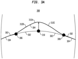
- Figure 3A illustrates an example of a graphical transition 300 between an original curve 302 and a new curve 304 according to this disclosure.
- the system 100 can identify two limit points 306 and 308 and define the limits (such as ends) of original curve 302 where a modification can occur.
- the system 100 can also identify an offset point 310 along the original curve 302 and can determine the point from which the original curve 302 can be moved in order to transition from the location of the original curve 302 to the location of the new curve 304.
- the offset point 310 can be a maximum offset point such that transition curve 312A has the greatest offset from the location of the original curve 302 at the offset point 310.
- the system 100 can move a transition curve 312A, which can be the portion of the original curve 302 between limit points (such as limit points 306 and 308) as the offset point 310 moves the original curve 302 to the position of the new curve 304 (such as to at least a point intersecting along the location of the new curve 304).
- the system 100 can identify two or more offset points.
- the system 100 can move at least the portion of the transition curve 312A between the offset points so that two or more points along the transition curve can intersect with two or more points along the new curve.
- the system 100 can also divide the transition curve 312A into at least two transition curve sections 312B and 312C.
- the transition curve sections 312B and 312C can have many different shapes.
- the system 100 can determine a displacement function (or delta curve) which can be applied to the transition curve section 312B in order to change or maintain the shape of a transition curve section 312B so that transition curve section 312B overlays (such as lays in the same position as and with the same shape of) the new curve 304.
- the displacement function of a transition curve section 312B can be modelled by the system 100 with a plurality of different displacement functions depending on the shape of the new curve 304.
- Figure 3B illustrates an example Cartesian coordinate graph of a displacement function 350 according to this disclosure.
- the displacement function 350 of a transition curve section 312B can be a cubic Bezier curve function with two control points: control point 354 controlling the movement of point 364 and control point 356 controlling the movement of point 366. It should be understood that these concepts are the same as if all four points 362, 364, 366, and 368 are considered control points and that points 362 and 368 are fixed so that only points 364 and 366 can move.
- Points 362 and 368 can represent the limit point 306 and offset point 310, respectively, of transition curve 312A illustrated in Figure 3A . Accordingly, points 362 and 368 may not have control points associated with them (or points 362 and 368 can be fixed control points) thereby fixing those points in a particular position (such as the relative positions of limit point 306 and offset point 310). In an embodiment, all of the points (such as points 362, 364, 366, and 368) can be manipulated and one or more of those points can be fixed.
- the displacement function 350 illustrated in Figure 3B can be used by the system 100 to shape the transition curve section 312B into the shape of the new curve 304 between the limit point 306 and the offset point 310 illustrated in Figure 3A .
- the transition curve 312A can have limit points (such as limit points 306 and 308) and offset points (such as offset point 310) with tangency constraints. Because of these tangency constraints, the system 100 can configure the control points 364 and 366 to limit movement to be horizontal only. The full control of such a displacement function 350 and the overlay of the transition curve section 312B over the new curve 304 can require two separate controls (one for a horizontal displacement of point 364 along with or using control point 354 and the other for a horizontal displacement of point 366 along with or using control point 356).
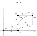
- FIG. 3C illustrates an example Cartesian coordinate graph of a displacement function 370 according to this disclosure. Similar to displacement function 350 of Figure 3B , displacement function 370 can have two control points: control point 374 controlling the movement of point 384 and control point 376 controlling the movement of point 386. Points 382 and 388 can represent the limit point 306 and offset point 310 of Figure 3A . Accordingly, the system 100 may not associate control points with points 382 and 388 thereby fixing those points in a particular position (such as the relative positions of limit point 306 and offset point 310).
- the system 100 can limit control points 374 and 376 of the displacement function 370 to only horizontal movement due to tangency constraints.
- the system 100 can lock control points 374 and 376 in unison by a locking line so that not only do control points 374 and 376 move in a horizontal direction, but control points 374 and 376 also move together in a horizontal direction.
- Figure 3C illustrates an example of control points locked in unison such that control point 374 and 376 can be joined and locked in unison by locking line 390 which in this embodiment is perpendicular to horizontal lines 392 and 394.
- the only remaining control is the horizontal movement of locking line 390.
- the system 100 can adjust the displacement function based on a relative horizontal position of (or a distance between) a locking line (or a point such as a midpoint along the locking line) and another horizontal position on the Cartesian coordinate graph.
- the system 100 can adjust a displacement function based on changing the relative horizontal position of a locking line (such as locking line 390) with a horizontal position of a point (such as points 382 and 388). For example, the system 100 can assign point 382 with Cartesian coordinate of (0,0) and the point 388 with Cartesian coordinate of (1,1). The horizontal distance of the locking line 390 from the point 382 or the horizontal distance of the locking line 390 from the point 388 (hereinafter "fullness" or “fullness value”) can determine the shape of the displacement function. The system 100 can adjust a shape of a displacement function based on the horizontal distance of the locking line 390 from the point 382 or the horizontal distance of the locking line 390 from the point 388.
- a horizontal distance between the locking line 390 and the horizontal coordinate of the point 388 can be indicated by a distance of line 396.
- the distance of line 396 can indicate a fullness value 398.
- the system 100 can adjust a shape of a displacement function in order to align the transition curve section 312B with the location of the new curve 304.
- the fullness value 398 can be a fraction of a horizontal distance of the transition curve sections 312B.
- the system 100 can apply the same procedure to the transition curve section 312C to overlay the transition curve section 312C over the new curve 304 (such as between the offset point 310 and the limit point 308).
- the system 100 can generate the transition curve section 312C based on the mirror image of the transition curve section 312B.
- the system 100 can then overlay the transition curve section 312C over the intended position of the new curve 304 from the offset point 310 to the limit point 308 without modelling the transition curve section 312C based on the shape of the new curve 304 and without adjusting the displacement function (via adjusting the fullness value) of the transition curve section 312C.
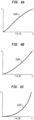
- Figures 4A, 4B, and 4C illustrate examples of displacement functions with different fullness values according to this disclosure.
- the transition curves 412A, 412B, and 412C illustrated in Figures 4A, 4B, and 4C can be indicative of displacement function 370 illustrated in Figure 3C with different fullness values 398.
- Figure 4A illustrates a transition curve 412A with displacement function 370 having a fullness value 398 of 0.30.
- Figure 4B illustrates a transition curve 412B with displacement function 370 having a fullness value 398 of 0.50.
- Figure 4C illustrates a transition curve 412C with displacement function 370 having a fullness value 398 of 0.70.
- transition curves or transition curve sections with only one tangency constraint can have three controls over the shape of the transition curve.
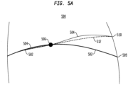
- Figure 5A illustrates an example of a graphical transition 500 between an original curve 502 and a new curve 504 according to this disclosure.
- two limit points 506 and 510 identified by the system 100, can define the limits (such as ends) of original curve 502 where a modification can occur.
- a limit point (such as limit point 510) can also be an offset point.
- the system 100 can identify that the limit point 510 is also the offset point and move the transition curve 512 from the original curve 502 to the location of new curve 504 by dragging the offset point 510 along line 509 until at least the offset point 510 intersects a point along the position of the new curve 504.
- the transition curve 512 can have many different shapes.
- the system 100 can determine a displacement function which can be applied to the transition curve 512 in order to change or maintain the shape of a transition curve 512 so that transition curve 512 overlays (such as lays in the same position as and with the same shape of) the new curve 504.
- the displacement function of a transition curve 512 can be modelled by the system 100 with a plurality of different curve functions depending on the intended shape of the new curve 504.
- Figure 5B illustrates an example Cartesian coordinate graph of a displacement function 520 according to this disclosure.
- the displacement function 520 of a transition curve can be a curve function with three control points: control point 524 controlling the movement of point 534, control point 526 controlling the movement of point 536, and control point 527 controlling the angle of line 537.
- Points 532 and 538 can represent the limit point 506 and offset point 510 of transition curve 512 illustrated in Figure 5A .
- points 532 and 538 may not have control points associated with them thereby fixing those points in a particular position (such as the relative positions of limit point 506 and offset point 510). It should be understood that these concepts can be the same as if points 532, 534, 536, 537, and 538 are all control points and control points 532 and 538 are fixed so that only the remaining control points move.
- the displacement function 520 illustrated in Figure 5B can be used by the system 100 to shape the transition curve 512 into the intended shape of the new curve 504 between the limit point 506 and the offset point 510 illustrated in Figure 5A .
- the transition curve 512 can have limit points (such as limit point 506) and offset point (such as offset point 510) with tangency constraints.
- the system 100 can configure the control points 524 to limit point 534 to horizontal movement.
- the full control of such a displacement function 520 and the overlay of the transition curve 512 over the intended location of the new curve 504 can require three separate controls (one for a horizontal displacement of point 534 using control point 524, one for the displacement of point 536 using control point 526, and one for changing the angle of line 537 using control point 527).
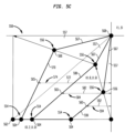
- FIG. 5C illustrates an example Cartesian coordinate graph of a displacement function 550 according to this disclosure. Similar to displacement function 520 of Figure 5B , displacement function 550 can have three control points: control point 554 controlling the movement of point 564, control point 556 controlling the movement of point 566, and control point 557 controlling the angle of line 567. Points 562 and 568 can represent the limit point 506 and offset point 510 of Figure 5A . Accordingly, the system 100 may not associate control points with points 562 and 568 thereby fixing those points in a particular position (such as the relative positions of limit point 506 and offset point 510).
- the system 100 can limit control point 564 of the displacement function 550 to only horizontal movement due to tangency constraints.
- the system 100 can determine the midpoint (such as midpoints 572, 582, and 592) of line 565 and the measure the horizontal distance between the midpoint of line 565 and a horizontal distance of one of the point 562 (which can represent the limit point 506 of Figure 5A ) or the point 568 (which can represent the offset point 510 of Figure 5A ) in order to determine a fullness value (such as fullness values 574, 584, and 594).
- the only remaining control is the horizontal movement of the midpoint of the line 565.
- the system 100 can adjust the fullness value of a displacement function based on a relative horizontal position of (or a distance between) a midpoint of the line 565 and another horizontal position on the Cartesian coordinate graph.
- the system 100 can adjust a fullness value of a displacement function based on changing the relative horizontal position of a midpoint of line 565 with a horizontal position of a point (such as points 562 and 568). For example, the system 100 can assign point 562 with Cartesian coordinate of (0,0) and the point 568 with Cartesian coordinate of (1,1). The horizontal distance of the midpoint (such as midpoints 572, 582, and 592) of line 565 from the point 562 or the horizontal distance of the midpoint of line 565 from the point 568 can determine a fullness value and the shape of the displacement function. For example, when the fullness value is 0.0, points 564 and 566 can be at the starting point (such as position (1,0)).
- Displacement functions 570, 580 and 590 as illustrated in Figure 5C can each represent displacement function 550 but with different fullness values.
- the system 100 can adjust a shape of a displacement function (for example from displacement function 570 to displacement function 580 and to displacement function 590) based on a fullness value (such as fullness values 574, 584, and 594) and in this case the horizontal distance of the midpoint of line 565 from the point 562 or the horizontal distance of the midpoint of line 565 from the point 568. Accordingly, by providing or determining a fullness value, the system 100 can adjust a shape of a displacement function in order to align the transition curve section 512 with the intended location of the new curve 504.
- the fullness value (such as fullness values 574, 584, and 594) can be a fraction of a horizontal distance of the transition curve 512.
- Figures 6A, 6B, and 6C illustrate examples of displacement functions with different fullness values according to this disclosure.
- the transition curves 612A, 612B, and 612C illustrated in Figures 6A, 6B, and 6C can be indicative of displacement function 570, 580, and 590 illustrated in Figure 5C with different fullness values 574, 584, and 594.
- Figure 6A illustrates a transition curve 612A with displacement function 570 having a fullness value 574 of 0.70.
- Figure 6B illustrates a transition curve 612B with displacement function 580 having a fullness value 584 of 0.50.
- Figure 6C illustrates a transition curve 612C with displacement function 590 having a fullness value 594 of 0.30.
- transition curves or transition curve sections with no tangency constraints can have four controls over the shape of the transition curve.
- Figure 7A illustrates an example of a graphical transition 700 between an original curve 702 and the intended location of the new curve 704 according to this disclosure.
- two limit points 706 and 710 identified by the system 100, can define the limits (such as ends) of original curve 702 where a modification can occur.
- a limit point (such as limit point 710) can also be an offset point.
- the system 100 can identify that the limit point 710 is also the offset point and move the transition curve 712 from the original curve 702 to the location of the new curve 704 by dragging the offset point 710 along line 709 until at least the offset point 710 intersects a point along the intended location of the new curve 704.
- the transition curve 712 can have many different shapes.
- the system 100 can determine a displacement function which can be applied to the transition curve 712 in order to change or maintain the shape of a transition curve 712 so that transition curve 712 overlays the new curve 704.
- the displacement function of a transition curve 712 can be modelled by the system 100 with a plurality of different displacement functions depending on the intended shape of the new curve 704.
- Figure 7B illustrates an example Cartesian coordinate graph of a displacement function 720 according to this disclosure.
- the displacement function 720 of a transition curve can be a cubic Bezier curve function with four control points: control point 723 controlling the angle of line 733, control point 724 controlling the movement of point 734, control point 726 controlling the movement of point 736, and control point 727 controlling the angle of line 727.
- Points 732 and 738 can represent the limit point 706 and offset point 710 of transition curve 712 illustrated in Figure 7A .
- points 732 and 738 may not have control points associated with them thereby fixing those points in a particular position (such as the relative positions of limit point 706 and offset point 710). It should be understood that these concepts can be the same as if points 732, 733, 734, 736, 737, and 738 are all control points and control points 732 and 738 are fixed so that only the remaining control points move.
- the displacement function 720 illustrated in Figure 5B can be used by the system 100 to shape the transition curve 712 into the intended shape of the new curve 704 between the limit point 706 and the offset point 710 illustrated in Figure 7A .
- the transition curve 712 can have points and lines (such as points 734 and 736 and lines 733 and 737) with no tangency constraints.
- the full control of such a displacement function 720 and the overlay of the transition curve 712 over the location of the new curve 704 can require four separate controls (one for changing the angle of line 733 using control point 723, one for the displacement of point 734 using control point 724, one for the displacement of point 736 using control point 726, and one for changing the angle of line 737 using control point 727).
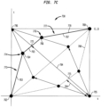
- FIG. 7C illustrates an example Cartesian coordinate graph of a displacement function 750 according to this disclosure. Similar to displacement function 720 of Figure 7B , displacement function 750 can have four control points: control point 773 controlling the angle of line 763, control point 774 controlling the movement of point 764, control point 776 controlling the movement of point 766, and control point 777 controlling the angle of line 767. Points 762 and 768 can represent the limit point 706 and offset point 710 of Figure 7A .
- the system 100 may not associate control points with points 762 and 768 thereby fixing those points in a particular position (such as the relative positions of limit point 706 and offset point 710).
- the system 100 can assign point 762 with Cartesian coordinate of (0,0) and the point 768 with Cartesian coordinate of (1,1).
- the system 100 can then determine the midpoint 775 of a line 765 based on a line 780 from Cartesian coordinate (0,1) to Cartesian coordinate (1,0) and determine a fullness value 784 based on the distance along the line 780 of the midpoint 775 of line 765 between the Cartesian coordinate (0,1) or the Cartesian coordinate (1,0).
- the system 100 can adjust the fullness value of a displacement function based on a relative position of (or a distance between) a midpoint 775 of the line 765 and another position on the Cartesian coordinate graph.
- the system 100 can adjust a fullness value of a displacement function based on changing the relative position of a midpoint 775 of line 765 with a position of a point. It should be understood, the system 100 can choose line 765 based on the effect that adjusting the position of the midpoint 775 of line 765 has on the control points (such as control points 723, 724, 726, and 727). Displacement functions 770 and 780 as illustrated in Figure 7C can each represent displacement function 750 but with different fullness values.
- the system 100 can adjust a shape of a displacement function (for example from displacement function 770 to displacement function 780) based on a fullness value (such as fullness values 784 and 794) and in this case the distance from the midpoint 775 of line 765 to the point 795 ((1,0) on the Cartesian coordinate graph) or the distance from the midpoint 775 of line 765 to the point 796 ((0,1) on the Cartesian coordinate graph).
- the fullness value 784 associated with displacement function 770 can be 0.75 and the fullness value 794 associated with displacement function 780 can be 0.25. Accordingly, by providing or determining a fullness value, the system 100 can adjust a shape of a displacement function in order to align the transition curve section 712 with the intended location of the new curve 704.
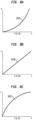
- Figures 8A, 8B, and 8C illustrate examples of displacement functions with different fullness values according to this disclosure.
- the transition curves 812A, 812B, and 812C illustrated in Figures 8A, 8B, and 8C can be indicative of displacement function 750 illustrated in Figure 7C with different fullness values 784 (or 794).
- Figure 8A illustrates a transition curve 812A with displacement function 750 having a fullness value 784 of 0.30.
- Figure 8B illustrates a transition curve 812B with displacement function 750 having a fullness value 784 of 0.50.
- Figure 8C illustrates a transition curve 812C with displacement function 750 having a fullness value 784 of 0.70.
- Figures 9A and 9B illustrate examples of CAD models 900A and 900B with shape changes from original curves 902A and 902B to transition curves 912A and 912B overlaying the intended positions of new curves 904A and 904B between limit points 906A and 908A as well as 906B and 908B, respectively, according to this disclosure.
- the curves can represent seams in a CAD model of a fabric.
- the system 100 may have previously pulled the offset points 910A and 910B to intersect with at least one point of the new curves 904A and 904B, respectively.
- New curves 904A and 904B can be represented by the same displacement function but can require different fullness values based on the variations in shape.
- the system 100 can modify the fullness value of the displacement function of the transition curve 912A to 0.70 so that transition curve 912A can overlay the intended position of new curve 904A.
- the system 100 can modify the fullness value of the displacement function of the transition curve 912B to 0.90 so that transition curve 912B can overlay the intended position of new curve 904B.
- the system 100 can delete the original curves 902A and 902B.
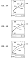
- Figures 10A, 10B, and 10C illustrate examples of CAD models 1000A, 1000B, and 1000C with shape changes from original curves 1002A, 1002B, and 1002C to transition curves 1012A, 1012B, and 1012C overlaying new curves 1004A, 1004B, and 1004C between limit points 1006A and 1010A, 1006B and 1010B, as well as 1006C and 1010C, respectively, according to this disclosure.
- the curves can represent seams in a CAD model of a fabric.
- Limit points 1010A, 1010B, and 1010C can also be offset points.
- the system 100 may have previously pulled the offset points 1010A, 1010B, and 1010C to intersect with at least one point of the new curves 1004A, 1004B, and 1004C, respectively.
- New curves 1004A, 1004B, and 1004C can be represented by the same displacement function but can require different fullness values based on the variations in shape. Accordingly, as shown in Figure 10A , the system 100 can modify the fullness value of the displacement function of the transition curve 1012A to 0.30 so that transition curve 1012A can overlay the intended position of new curve 1004A. Furthermore, as shown in Figure 10B , the system 100 can modify the fullness value of the displacement function of the transition curve 1012B to 0.50 so that transition curve 1012B can overlay the intended position of new curve 1004B.
- the system 100 can modify the fullness value of the displacement function of the transition curve 1012C to 0.80 so that transition curve 1012C can overlay the intended position of new curve 1004C.
- the system 100 can delete the original curves 1002A, 1002B, and 1002C.
- the system 100 can modify one or more connecting curves or seams intersecting with the original curve or terminating at the original curve so that the one or more connecting curves or seams intersect with the new curve or terminate at the new curve.
- Figure 11A illustrates an example of a CAD model system 1100A with an original curve 1102A, a new curve 1104A, and one or more connecting curves 1114A and 1116A according to this disclosure. As illustrated in Figure 11A , the one or more connecting curves 1114A and 1116A can terminate at the original curve 1102A.
- the system 100 can recognize the one or more connecting curves 1114A and 1116A and that the one or more connecting curves 1114A and 1116A terminate at the original curve 1102A.
- the system 100 can also identify the new curve 1104A and modify the one or more connecting curves 1114A and 1116A so that they terminate at new curve 1104A instead of the original curve 1102A or the location of the original curve 1102A before the original curve 1102A was deleted.
- the system 100 can trim, extend, bend, or straighten one or more connecting curves so that the connecting curve aligns with new curve as they previously aligned with the original curve.
- Figure 11B illustrates an example of a CAD model system 1100B with an indication of the location of the original curve 1102B, a new curve 1104B, and one or more connecting curves 1114B and 1116B according to this disclosure.
- the system 100 has modified the one or more connecting curves 1114B and 1116B so that they terminate at the new curve 1104B instead of the location of the original curve 1102B.
- the system 100 can also modify one or more nearby curves that may not intersect with an original curve when an original curve is replaced with a new curve so that the distances or relative distances of the one or more nearby curves and new curve is the same as the distances or relative distances of the one or more nearby curves and the location of the original curve.
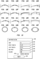
- Figure 12 illustrates an example diagram of curve or seam modification use cases according to this disclosure.
- Diagrams (a)-(p) illustrate different curve or seam modifications with different displacement functions.
- the system 100 can modified a curve or seam in a CAD file from an original curve to a new curve using a transition curve.
- the system 100 can modify a curve or seam in a CAD file many different ways including by moving an offset point and changing a fullness value.
- Diagrams (a)-(p) of Figure 12 illustrate sixteen use case examples of how curves can be modified by the system 100.
- Figure 13 illustrates an example diagram of a user interface associated with the system 100 according to this disclosure.
- the system 100 via the user interface 1318 can be configured to receive inputs to modify a curve or seam.
- the system 100 can receive one or more inputs in a curve type space 1320 indicating a type of curve to be implemented as the new curve.
- the system 100 can receive one or more inputs in an offset point space 1322 indicating the location of one or more offset points of a transition curve to be implemented when form the new curve.
- the system 100 can receive one or more inputs in a limit point space 1324 indicating the location of one or more limit points of a transition curve to be implemented when forming the new curve.
- the system 100 can receive one or more inputs in a maximum offset space 1326 indicating the maximum perpendicular distance from a tangent line of one or more offset points that a transition curve can moved when forming the new curve.
- the system 100 can receive one or more inputs in a fullness value space 1328 indicating the fullness value of a displacement function of a transition curve so that the transition curve can overlay the new curve.
- the system 100 can receive an input from the modify box 1330 to implement any one or more of the above parameters. For example, after the system 100 has positioned the transition curve in the intended location of the new curve, the curve can be further modified based on any of the above parameters or inputs.
- Reverse direction box 1332 can be used to change the direction of the maximum offset 1326. For example, if maximum offset is 20mm and the reverse direction box 1332 is not selected, the maximum offset can be 20mm in a first direction. Conversely, if the reverse direction box 1332 is selected, the maximum offset can be 20mm in a second direction opposite the first direction.
- Figure 14 illustrates an example method 1400 to be performed by a data processing system 100 in a CAD system on a CAD model with one or more curves according to this disclosure.
- the data processing system 100 can identify an original curve and an intended location of a new curve in a CAD model.
- the data processing system 100 can be configured to identify two or more limit points along the original curve when identifying the original curve.
- the data processing system 100 can generate a transition curve from the original curve.
- the data processing system 100 can generate a transition curve from a portion of the original curve between two limit points.
- the data processing system 100 can determine a displacement function of the new curve and apply the displacement function to the transition curve.
- the displacement function can include two or more control points.
- the data processing system 100 can combine two or more control points of the displacement function into one transition curve control point.
- the transition curve control point can be controlled based on a fullness value.
- the data processing system 100 can adjust the transition curve control point based on the fullness value so that transition curve overlays the intended location of the new curve.
- the fullness value can be a relative distance in a Cartesian coordinate graph between a point along the displacement function and another point in the Cartesian coordinate graph.
- the data processing system 100 can identify a midpoint of a line of the displacement function in a Cartesian coordinate graph and can adjust a distance from the midpoint of the line of the displacement function to point in the Cartesian coordinate graph in order to adjust the transition curve control point based on the fullness value.
- the system 100 can modify one or more connecting curves or seams intersecting with the original curve or terminating at the original curve so that the one or more connecting curves or seams intersect with the new curve or terminate at the new curve.
- machine usable/readable or computer usable/readable mediums include: nonvolatile, hard-coded type mediums such as read only memories (ROMs) or erasable, electrically programmable read only memories (EEPROMs), and user-recordable type mediums such as floppy disks, hard disk drives and compact disk read only memories (CD-ROMs) or digital versatile disks (DVDs).
- ROMs read only memories
- EEPROMs electrically programmable read only memories
- user-recordable type mediums such as floppy disks, hard disk drives and compact disk read only memories (CD-ROMs) or digital versatile disks (DVDs).
Landscapes
- Physics & Mathematics (AREA)
- Engineering & Computer Science (AREA)
- Geometry (AREA)
- Theoretical Computer Science (AREA)
- General Physics & Mathematics (AREA)
- Evolutionary Computation (AREA)
- Computer Hardware Design (AREA)
- General Engineering & Computer Science (AREA)
- Pure & Applied Mathematics (AREA)
- Mathematical Optimization (AREA)
- Mathematical Analysis (AREA)
- Computational Mathematics (AREA)
- Architecture (AREA)
- Software Systems (AREA)
- Image Generation (AREA)
Claims (11)
- Verfahren zum Modifizieren einer Nahtkurve in einem Computer-Aided-Design(CAD - rechnergestütztes Design)-Modell, um den Ort und die Form einer neuen Nahtkurve zu erhalten und um eine Nahtnetzwerkkonnektivität beizubehalten, wobei das Verfahren durch ein Datenverarbeitungssystem (100) durchgeführt wird und Folgendes umfasst:a) Empfangen wenigstens einer Eingabe durch eine Benutzeroberfläche 1318 zum Modifizieren einer Kurve oder einer Naht, wobei wenigstens eine Eingabe aus einer Gruppe ausgewählt wird, die eine Art einer Kurve, die als eine neue Kurve zu implementieren ist, einen Ort eines oder mehrerer Versatzpunkte, einen maximalen Versatzraum, einen Ort eines oder mehrerer Grenzpunkte einer Übergangkurve und einen Fülligkeitswert, der beim Bilden der neuen Kurve zu implementieren ist, umfasst,b) Identifizieren (1405) einer ursprünglichen Kurve (202) und eines beabsichtigten Orts der neuen Kurve (216) in dem CAD-Modell, wobei das Identifizieren das Identifizieren von wenigstens zwei Grenzpunkten (306, 308) zum Definieren der Grenzen oder Enden einer ursprünglichen Kurve (302), wo eine Modifikation auftreten kann, und eines Versatzpunktes (310) entlang der ursprünglichen Kurve (202, 302) beinhaltet, und Bestimmen des Punkts, von dem die ursprüngliche Kurve 302 bewegt werden kann, um von dem Ort der ursprünglichen Kurve 302 zu dem Ort der neuen Kurve 304 überzugehen;c) Erzeugen (1410) einer Übergangskurve (312A) aus der ursprünglichen Kurve (202) durch den Versatzpunkt (310), wobei die ursprüngliche Kurve (302) zu der Position der neuen Kurve (304) bewegt wird, so dass wenigstens ein Versatzpunkt (310) der Übergangskurve entlang des Ortes der neuen Kurve (304) geschnitten wird;d) Bestimmen (1415) einer Verschiebungsfunktion (350) der neuen Kurve (216) basierend auf einem Fülligkeitswert und Anwenden der Verschiebungsfunktion auf die Übergangskurve (312A), so dass die Übergangskurve (312B, 312A) auf die neue Kurve (304) an der gleichen Position und mit der gleichen Form überlagert wird, wobei die Verschiebungsfunktion (350) zwei oder mehr Steuerungen (354, 356; 374; 376) beinhaltet, die eine Steuerbewegung eines assoziierten Punkts (384, 386) steuern, so dass die Übergangskurve (312A, 312B) zu der Form der neuen Kurve geformt wird;e) Kombinieren (1420) der zwei oder mehr Steuerungen (354, 356; 374, 376) zu einer Übergangskurvensteuerung, so dass eine Bewegung der assoziierten Punkte (384, 386) in Übereinstimmung arretiert wird;f) Anpassen (1425) der Übergangskurvensteuerung basierend auf einem Fülligkeitswert (398), so dass die Übergangskurve (312A) auf den Ort der neuen Kurve (216) überlagert wird, wobei der Fülligkeitswert (398) eine horizontale Entfernung in einem Graphen mit kartesischen Koordinaten zwischen einem Mittelpunkt einer Linie (396) entlang der Verschiebungsfunktion und einem anderen Punkt (382, 388) in dem Graphen mit kartesischen Koordinaten ist; undg) Modifizieren einer oder mehrerer Verbindungskurven (204, 206, 208, 210), die an einem oder mehreren Punkten entlang der ursprünglichen Kurve (202) enden, so dass die eine oder mehreren Verbindungskurven (204, 206, 208, 210) an einem oder mehreren Punkten entlang der Übergangskurve (312A) enden.
- Verfahren nach Anspruch 1, das ferner Löschen der ursprünglichen Kurve (202) umfasst, nachdem die Übergangskurve (312A) auf dem Ort der neuen Kurve (216) überlagert wurde.
- Verfahren nach einem der vorhergehenden Ansprüche, wobei das Identifizieren der ursprünglichen Kurve (202) Identifizieren von zwei oder mehr Grenzpunkten (306, 308) entlang der ursprünglichen Kurve (202) umfasst.
- Verfahren nach Anspruch 1, das ferner Versetzen wenigstens eines Versatzpunktes (310) entlang der Übergangskurve (312A) für eine Entfernung umfasst, so dass die Übergangskurve (312A) wenigstens an einem Punkt entlang des Ortes der neuen Kurve (216) geschnitten wird, bevor der Übergangskurvensteuerpunkt angepasst wird.
- Verfahren nach Anspruch 1, wobei das Anpassen der Übergangskurve basierend auf dem Fülligkeitswert (398) Identifizieren eines Mittelpunkts einer Linie der Verschiebungsfunktion in dem Graphen mit kartesischen Koordinaten und Anpassen einer Entfernung von dem Mittelpunkt der Linie der Verschiebungsfunktion zu einem anderen Punkt in dem Graphen mit kartesischen Koordinaten umfasst.
- Datenverarbeitungssystem (100) für ein Computer-Aided-Design(CAD)-System, wobei das Datenverarbeitungssystem (100) Folgendes umfasst:i) einen Prozessor (102); undii) einen zugänglichen Speicher (108), wobei das Datenverarbeitungssystem (100) insbesondere zu Folgendem ausgelegt ist:a) Empfangen wenigstens einer Eingabe durch eine Benutzeroberfläche 1318 zum Modifizieren einer Kurve oder einer Naht, wobei wenigstens eine Eingabe aus einer Gruppe ausgewählt wird, die eine Art einer Kurve, die als eine neue Kurve zu implementieren ist, einen Ort eines oder mehrerer Versatzpunkte, einen maximalen Versatzraum (1326), einen Ort eines oder mehrerer Grenzpunkte einer Übergangkurve, der beim Bilden der neuen Kurve zu implementieren ist, und einen Fülligkeitswert umfasst,b) Identifizieren (1405) einer ursprünglichen Kurve (202, 302) und eines beabsichtigten Orts der neuen Kurve (216; 304) in dem CAD-Modell, wobei das Identifizieren das Identifizieren von wenigstens zwei Grenzpunkten (306, 308) zum Definieren der Grenzen oder Enden einer ursprünglichen Kurve (302), wo eine Modifikation auftreten kann, und eines Versatzpunktes (310) entlang der ursprünglichen Kurve (202, 302) beinhaltet, und Bestimmen des Punkts, von dem die ursprüngliche Kurve 302 bewegt werden kann, um von dem Ort der ursprünglichen Kurve 302 zu dem Ort der neuen Kurve 304 überzugehen;c) Erzeugen (1410) einer Übergangskurve (312A) aus der ursprünglichen Kurve (202) durch den Versatzpunkt (310), wobei die ursprüngliche Kurve (302) zu der Position der neuen Kurve (304) bewegt wird, so dass wenigstens ein Versatzpunkt (310) der Übergangskurve entlang des Ortes der neuen Kurve (304) geschnitten wird;d) Bestimmen (1415) einer Verschiebungsfunktion (350) der neuen Kurve (216) basierend auf einem Fülligkeitswert und Anwenden der Verschiebungsfunktion auf die Übergangskurve (312A), so dass die Übergangskurve (312B, 312A) auf die neue Kurve (304) an der gleichen Position und mit der gleichen Form überlagert wird, wobei die Verschiebungsfunktion (350) zwei oder mehr Steuerungen (354, 356; 374; 376) beinhaltet, die eine Steuerbewegung eines assoziierten Punkts (384, 386) steuern, so dass die Übergangskurve (312A, 312B) zu der Form der neuen Kurve geformt wird;e) Kombinieren (1420) der zwei oder mehr Steuerungen (354, 356; 374, 376) zu einer Übergangskurvensteuerung, so dass eine Bewegung der assoziierten Punkte (384, 386) in Übereinstimmung arretiert wird;f) Anpassen (1425) der Übergangskurvensteuerung basierend auf einem Fülligkeitswert (398), so dass eine Übergangskurve (312A) auf den Ort der neuen Kurve (216) überlagert wird, wobei der Fülligkeitswert (398) eine horizontale Entfernung in einem Graphen mit kartesischen Koordinaten zwischen einem Mittelpunkt einer Linie (396) entlang der Verschiebungsfunktion und einem anderen Punkt (382, 388) in dem Graphen mit kartesischen Koordinaten ist; undg) Modifizieren einer oder mehrerer Verbindungskurven (204, 206, 208, 210), die an einem oder mehreren Punkten entlang der ursprünglichen Kurve (202) enden, so dass die eine oder mehreren Verbindungskurven (204, 206, 208, 210) an einem oder mehreren Punkten entlang der Übergangskurve (312A) enden.
- Datenverarbeitungssystem nach Anspruch 6, wobei das Datenverarbeitungssystem (100) ferner insbesondere zum Löschen der ursprünglichen Kurve (202) ausgelegt ist, nachdem die Übergangskurve (312A) auf den Ort der neuen Kurve (216) überlagert wurde.
- Datenverarbeitungssystem nach einem der vorhergehenden Systemansprüche, wobei das Datenverarbeitungssystem (100) ferner insbesondere zum Identifizieren von zwei oder mehr Grenzpunkten (306, 308) entlang der ursprünglichen Kurve (202) ausgelegt ist, wenn die ursprüngliche Kurve (202) identifiziert wird.
- Datenverarbeitungssystem nach einem der vorhergehenden Systemansprüche, wobei das Datenverarbeitungssystem (100) ferner insbesondere zum Versetzen wenigstens eines Punktes (310) entlang der Übergangskurve (312A) für eine Entfernung ausgelegt ist, so dass die Übergangskurve (312A) wenigstens an einem Punkt entlang des Ortes der neuen Kurve (216) geschnitten wird, bevor der Übergangskurvensteuerpunkt angepasst wird.
- Datenverarbeitungssystem (100) nach Anspruch 1, wobei das Datenverarbeitungssystem (100) ferner insbesondere zum Identifizieren eines Mittelpunkts einer Linie der Verschiebungsfunktion in dem Graphen mit kartesischen Koordinaten und Anpassen einer Entfernung von dem Mittelpunkt der Linie der Verschiebungsfunktion zu dem Punkt in dem Graphen mit kartesischen Koordinaten ausgelegt ist, um den Übergangskurvensteuerpunkt basierend auf dem Fülligkeitswert (398) anzupassen.
- Nichtflüchtiges computerlesbares Medium, das mit ausführbaren Anweisungen codiert ist, die, wenn sie ausgeführt werden, ein oder mehrere Datenverarbeitungssysteme (100) zum Durchführen eines Verfahrens nach einem der Ansprüche 1 bis 5 veranlassen.
Applications Claiming Priority (1)
| Application Number | Priority Date | Filing Date | Title |
|---|---|---|---|
| US14/321,140 US10095810B2 (en) | 2014-07-01 | 2014-07-01 | Seam modification for 3D CAD models |
Publications (2)
| Publication Number | Publication Date |
|---|---|
| EP2963572A1 EP2963572A1 (de) | 2016-01-06 |
| EP2963572B1 true EP2963572B1 (de) | 2024-10-16 |
Family
ID=53487273
Family Applications (1)
| Application Number | Title | Priority Date | Filing Date |
|---|---|---|---|
| EP15173611.3A Active EP2963572B1 (de) | 2014-07-01 | 2015-06-24 | Nahtmodifikation für 3d-cad-modelle |
Country Status (2)
| Country | Link |
|---|---|
| US (1) | US10095810B2 (de) |
| EP (1) | EP2963572B1 (de) |
Families Citing this family (6)
| Publication number | Priority date | Publication date | Assignee | Title |
|---|---|---|---|---|
| EP3118651B1 (de) * | 2015-07-17 | 2021-04-21 | Hexagon Technology Center GmbH | Laufzeitmessvorrichtung und laufzeitmessverfahren mit ambiguitätslösung in echtzeit |
| EP3937132B1 (de) * | 2018-04-09 | 2025-05-28 | BlackBerry Limited | Verfahren und vorrichtungen zur binären entropiecodierung von punktwolken |
| CN110609012A (zh) * | 2018-06-15 | 2019-12-24 | 中兴通讯股份有限公司 | 一种气体浓度检测方法及系统 |
| US11741270B2 (en) * | 2019-04-30 | 2023-08-29 | Siemens Industry Software Inc. | Computer aided design (CAD)-based foam part generation for seat designs |
| CN112614209B (zh) * | 2020-12-30 | 2024-02-20 | 凌云光技术股份有限公司 | 一种流程图刷新时的元素重绘方法及系统 |
| CN116051674B (zh) * | 2022-12-29 | 2025-11-11 | 杭州海康威视系统技术有限公司 | 一种电子白板线条绘制方法、电子白板及存储介质 |
Family Cites Families (2)
| Publication number | Priority date | Publication date | Assignee | Title |
|---|---|---|---|---|
| DE102006010610A1 (de) * | 2006-03-06 | 2007-09-13 | Fraunhofer-Gesellschaft zur Förderung der angewandten Forschung e.V. | Einprägen von Wasserzeichen in ein Modell einer linienartigen oder flächenartigen Form |
| US9336628B2 (en) * | 2008-05-08 | 2016-05-10 | United Technologies Corporation | Systems and methods involving surface fitting |
-
2014
- 2014-07-01 US US14/321,140 patent/US10095810B2/en active Active
-
2015
- 2015-06-24 EP EP15173611.3A patent/EP2963572B1/de active Active
Also Published As
| Publication number | Publication date |
|---|---|
| US10095810B2 (en) | 2018-10-09 |
| EP2963572A1 (de) | 2016-01-06 |
| US20160004790A1 (en) | 2016-01-07 |
Similar Documents
| Publication | Publication Date | Title |
|---|---|---|
| EP2963572A1 (de) | Nahtmodifikation für 3d-cad-modelle | |
| KR102060839B1 (ko) | 3d 모델링된 객체의 설계 | |
| JP4991423B2 (ja) | コンピュータにより実施される、パラメトリックな曲面を作成するプロセス | |
| JP4943542B2 (ja) | 薄壁領域を有する3次元物体の構築方法 | |
| JP7134027B2 (ja) | 自動繊維配置における繊維誘導のためにエッジ長差を測定するシステム及び方法 | |
| US20160121557A1 (en) | Method for defining fiber trajectories from curves or constraint grid | |
| JP2017205975A (ja) | 3次元データ生成装置、3次元造形装置、造形物の製造方法及びプログラム | |
| US20160121558A1 (en) | Method for defining fiber trajectories from a vector field | |
| US20130271459A1 (en) | Systems and methods of editing graphical data | |
| Lozano et al. | A design algorithm to model fibre paths for manufacturing of structurally optimised composite laminates | |
| JP7477279B2 (ja) | B-Repスキンの3D設計 | |
| US20260120409A1 (en) | Computer aided automated shape generation of three-dimensional geometries | |
| US9582616B2 (en) | Method for representing and generating a flat pattern for a composite ply that folds over itself | |
| JP2017162448A (ja) | 複合部品の外面の設計 | |
| Pan et al. | Development of rapid prototyping slicing software based on STL model | |
| US20130289946A1 (en) | Curve chain connections under surface, distance, and shape constraints | |
| US9984503B2 (en) | Systems and methods of updating graphical objects | |
| US9235659B2 (en) | Local behavior in a variational system | |
| JP6449703B2 (ja) | 形状変形装置および形状変形用プログラム | |
| US11292201B2 (en) | Additive swept wedge buildup toolpath | |
| JP2016207055A (ja) | 形状変形装置および形状変形用プログラム | |
| US9400854B2 (en) | Aerospace joggle on multiple adjacent web faces with intersecting runouts | |
| CN116136917A (zh) | 具有几何形状过滤以促进制造的计算机辅助设计 | |
| JP5806169B2 (ja) | 設計データ生成装置、その生成方法及びプログラム | |
| Chen et al. | Enhanced Toolpath Planning for Fused Filament Fabrication |
Legal Events
| Date | Code | Title | Description |
|---|---|---|---|
| PUAI | Public reference made under article 153(3) epc to a published international application that has entered the european phase |
Free format text: ORIGINAL CODE: 0009012 |
|
| AK | Designated contracting states |
Kind code of ref document: A1 Designated state(s): AL AT BE BG CH CY CZ DE DK EE ES FI FR GB GR HR HU IE IS IT LI LT LU LV MC MK MT NL NO PL PT RO RS SE SI SK SM TR |
|
| AX | Request for extension of the european patent |
Extension state: BA ME |
|
| 17P | Request for examination filed |
Effective date: 20160705 |
|
| RBV | Designated contracting states (corrected) |
Designated state(s): AL AT BE BG CH CY CZ DE DK EE ES FI FR GB GR HR HU IE IS IT LI LT LU LV MC MK MT NL NO PL PT RO RS SE SI SK SM TR |
|
| STAA | Information on the status of an ep patent application or granted ep patent |
Free format text: STATUS: EXAMINATION IS IN PROGRESS |
|
| 17Q | First examination report despatched |
Effective date: 20190805 |
|
| RAP1 | Party data changed (applicant data changed or rights of an application transferred) |
Owner name: SIEMENS INDUSTRY SOFTWARE INC. |
|
| REG | Reference to a national code |
Ref country code: DE Ref legal event code: R079 Free format text: PREVIOUS MAIN CLASS: G06F0017500000 Ipc: G06F0030170000 Ref country code: DE Ref legal event code: R079 Ref document number: 602015090145 Country of ref document: DE Free format text: PREVIOUS MAIN CLASS: G06F0017500000 Ipc: G06F0030170000 |
|
| GRAP | Despatch of communication of intention to grant a patent |
Free format text: ORIGINAL CODE: EPIDOSNIGR1 |
|
| STAA | Information on the status of an ep patent application or granted ep patent |
Free format text: STATUS: GRANT OF PATENT IS INTENDED |
|
| RIC1 | Information provided on ipc code assigned before grant |
Ipc: G06F 30/17 20200101AFI20240430BHEP |
|
| INTG | Intention to grant announced |
Effective date: 20240523 |
|
| GRAS | Grant fee paid |
Free format text: ORIGINAL CODE: EPIDOSNIGR3 |
|
| GRAA | (expected) grant |
Free format text: ORIGINAL CODE: 0009210 |
|
| STAA | Information on the status of an ep patent application or granted ep patent |
Free format text: STATUS: THE PATENT HAS BEEN GRANTED |
|
| AK | Designated contracting states |
Kind code of ref document: B1 Designated state(s): AL AT BE BG CH CY CZ DE DK EE ES FI FR GB GR HR HU IE IS IT LI LT LU LV MC MK MT NL NO PL PT RO RS SE SI SK SM TR |
|
| REG | Reference to a national code |
Ref country code: GB Ref legal event code: FG4D |
|
| REG | Reference to a national code |
Ref country code: CH Ref legal event code: EP |
|
| REG | Reference to a national code |
Ref country code: IE Ref legal event code: FG4D |
|
| REG | Reference to a national code |
Ref country code: DE Ref legal event code: R096 Ref document number: 602015090145 Country of ref document: DE |
|
| REG | Reference to a national code |
Ref country code: LT Ref legal event code: MG9D |
|
| REG | Reference to a national code |
Ref country code: NL Ref legal event code: MP Effective date: 20241016 |
|
| REG | Reference to a national code |
Ref country code: AT Ref legal event code: MK05 Ref document number: 1733507 Country of ref document: AT Kind code of ref document: T Effective date: 20241016 |
|
| PG25 | Lapsed in a contracting state [announced via postgrant information from national office to epo] |
Ref country code: NL Free format text: LAPSE BECAUSE OF FAILURE TO SUBMIT A TRANSLATION OF THE DESCRIPTION OR TO PAY THE FEE WITHIN THE PRESCRIBED TIME-LIMIT Effective date: 20241016 |
|
| PG25 | Lapsed in a contracting state [announced via postgrant information from national office to epo] |
Ref country code: NL Free format text: LAPSE BECAUSE OF FAILURE TO SUBMIT A TRANSLATION OF THE DESCRIPTION OR TO PAY THE FEE WITHIN THE PRESCRIBED TIME-LIMIT Effective date: 20241016 |
|
| PG25 | Lapsed in a contracting state [announced via postgrant information from national office to epo] |
Ref country code: IS Free format text: LAPSE BECAUSE OF FAILURE TO SUBMIT A TRANSLATION OF THE DESCRIPTION OR TO PAY THE FEE WITHIN THE PRESCRIBED TIME-LIMIT Effective date: 20250216 Ref country code: HR Free format text: LAPSE BECAUSE OF FAILURE TO SUBMIT A TRANSLATION OF THE DESCRIPTION OR TO PAY THE FEE WITHIN THE PRESCRIBED TIME-LIMIT Effective date: 20241016 Ref country code: PT Free format text: LAPSE BECAUSE OF FAILURE TO SUBMIT A TRANSLATION OF THE DESCRIPTION OR TO PAY THE FEE WITHIN THE PRESCRIBED TIME-LIMIT Effective date: 20250217 |
|
| PG25 | Lapsed in a contracting state [announced via postgrant information from national office to epo] |
Ref country code: FI Free format text: LAPSE BECAUSE OF FAILURE TO SUBMIT A TRANSLATION OF THE DESCRIPTION OR TO PAY THE FEE WITHIN THE PRESCRIBED TIME-LIMIT Effective date: 20241016 |
|
| PG25 | Lapsed in a contracting state [announced via postgrant information from national office to epo] |
Ref country code: BG Free format text: LAPSE BECAUSE OF FAILURE TO SUBMIT A TRANSLATION OF THE DESCRIPTION OR TO PAY THE FEE WITHIN THE PRESCRIBED TIME-LIMIT Effective date: 20241016 |
|
| PG25 | Lapsed in a contracting state [announced via postgrant information from national office to epo] |
Ref country code: ES Free format text: LAPSE BECAUSE OF FAILURE TO SUBMIT A TRANSLATION OF THE DESCRIPTION OR TO PAY THE FEE WITHIN THE PRESCRIBED TIME-LIMIT Effective date: 20241016 |
|
| PG25 | Lapsed in a contracting state [announced via postgrant information from national office to epo] |
Ref country code: NO Free format text: LAPSE BECAUSE OF FAILURE TO SUBMIT A TRANSLATION OF THE DESCRIPTION OR TO PAY THE FEE WITHIN THE PRESCRIBED TIME-LIMIT Effective date: 20250116 |
|
| PG25 | Lapsed in a contracting state [announced via postgrant information from national office to epo] |
Ref country code: AT Free format text: LAPSE BECAUSE OF FAILURE TO SUBMIT A TRANSLATION OF THE DESCRIPTION OR TO PAY THE FEE WITHIN THE PRESCRIBED TIME-LIMIT Effective date: 20241016 Ref country code: GR Free format text: LAPSE BECAUSE OF FAILURE TO SUBMIT A TRANSLATION OF THE DESCRIPTION OR TO PAY THE FEE WITHIN THE PRESCRIBED TIME-LIMIT Effective date: 20250117 Ref country code: LV Free format text: LAPSE BECAUSE OF FAILURE TO SUBMIT A TRANSLATION OF THE DESCRIPTION OR TO PAY THE FEE WITHIN THE PRESCRIBED TIME-LIMIT Effective date: 20241016 |
|
| PG25 | Lapsed in a contracting state [announced via postgrant information from national office to epo] |
Ref country code: PL Free format text: LAPSE BECAUSE OF FAILURE TO SUBMIT A TRANSLATION OF THE DESCRIPTION OR TO PAY THE FEE WITHIN THE PRESCRIBED TIME-LIMIT Effective date: 20241016 |
|
| PG25 | Lapsed in a contracting state [announced via postgrant information from national office to epo] |
Ref country code: RS Free format text: LAPSE BECAUSE OF FAILURE TO SUBMIT A TRANSLATION OF THE DESCRIPTION OR TO PAY THE FEE WITHIN THE PRESCRIBED TIME-LIMIT Effective date: 20250116 |
|
| PG25 | Lapsed in a contracting state [announced via postgrant information from national office to epo] |
Ref country code: SM Free format text: LAPSE BECAUSE OF FAILURE TO SUBMIT A TRANSLATION OF THE DESCRIPTION OR TO PAY THE FEE WITHIN THE PRESCRIBED TIME-LIMIT Effective date: 20241016 |
|
| PG25 | Lapsed in a contracting state [announced via postgrant information from national office to epo] |
Ref country code: DK Free format text: LAPSE BECAUSE OF FAILURE TO SUBMIT A TRANSLATION OF THE DESCRIPTION OR TO PAY THE FEE WITHIN THE PRESCRIBED TIME-LIMIT Effective date: 20241016 |
|
| REG | Reference to a national code |
Ref country code: DE Ref legal event code: R097 Ref document number: 602015090145 Country of ref document: DE |
|
| PG25 | Lapsed in a contracting state [announced via postgrant information from national office to epo] |
Ref country code: EE Free format text: LAPSE BECAUSE OF FAILURE TO SUBMIT A TRANSLATION OF THE DESCRIPTION OR TO PAY THE FEE WITHIN THE PRESCRIBED TIME-LIMIT Effective date: 20241016 |
|
| PGFP | Annual fee paid to national office [announced via postgrant information from national office to epo] |
Ref country code: FR Payment date: 20250613 Year of fee payment: 11 |
|
| PG25 | Lapsed in a contracting state [announced via postgrant information from national office to epo] |
Ref country code: RO Free format text: LAPSE BECAUSE OF FAILURE TO SUBMIT A TRANSLATION OF THE DESCRIPTION OR TO PAY THE FEE WITHIN THE PRESCRIBED TIME-LIMIT Effective date: 20241016 |
|
| PG25 | Lapsed in a contracting state [announced via postgrant information from national office to epo] |
Ref country code: SK Free format text: LAPSE BECAUSE OF FAILURE TO SUBMIT A TRANSLATION OF THE DESCRIPTION OR TO PAY THE FEE WITHIN THE PRESCRIBED TIME-LIMIT Effective date: 20241016 |
|
| PG25 | Lapsed in a contracting state [announced via postgrant information from national office to epo] |
Ref country code: CZ Free format text: LAPSE BECAUSE OF FAILURE TO SUBMIT A TRANSLATION OF THE DESCRIPTION OR TO PAY THE FEE WITHIN THE PRESCRIBED TIME-LIMIT Effective date: 20241016 |
|
| PG25 | Lapsed in a contracting state [announced via postgrant information from national office to epo] |
Ref country code: IT Free format text: LAPSE BECAUSE OF FAILURE TO SUBMIT A TRANSLATION OF THE DESCRIPTION OR TO PAY THE FEE WITHIN THE PRESCRIBED TIME-LIMIT Effective date: 20241016 |
|
| PLBE | No opposition filed within time limit |
Free format text: ORIGINAL CODE: 0009261 |
|
| STAA | Information on the status of an ep patent application or granted ep patent |
Free format text: STATUS: NO OPPOSITION FILED WITHIN TIME LIMIT |
|
| PG25 | Lapsed in a contracting state [announced via postgrant information from national office to epo] |
Ref country code: SE Free format text: LAPSE BECAUSE OF FAILURE TO SUBMIT A TRANSLATION OF THE DESCRIPTION OR TO PAY THE FEE WITHIN THE PRESCRIBED TIME-LIMIT Effective date: 20241016 |
|
| 26N | No opposition filed |
Effective date: 20250717 |
|
| PGFP | Annual fee paid to national office [announced via postgrant information from national office to epo] |
Ref country code: DE Payment date: 20250820 Year of fee payment: 11 |
|
| PGFP | Annual fee paid to national office [announced via postgrant information from national office to epo] |
Ref country code: GB Payment date: 20250710 Year of fee payment: 11 |
|
| REG | Reference to a national code |
Ref country code: CH Ref legal event code: H13 Free format text: ST27 STATUS EVENT CODE: U-0-0-H10-H13 (AS PROVIDED BY THE NATIONAL OFFICE) Effective date: 20260127 |
|
| PG25 | Lapsed in a contracting state [announced via postgrant information from national office to epo] |
Ref country code: MC Free format text: LAPSE BECAUSE OF FAILURE TO SUBMIT A TRANSLATION OF THE DESCRIPTION OR TO PAY THE FEE WITHIN THE PRESCRIBED TIME-LIMIT Effective date: 20241016 |
|
| PG25 | Lapsed in a contracting state [announced via postgrant information from national office to epo] |
Ref country code: LU Free format text: LAPSE BECAUSE OF NON-PAYMENT OF DUE FEES Effective date: 20250624 |
|
| REG | Reference to a national code |
Ref country code: BE Ref legal event code: MM Effective date: 20250630 |
|
| PG25 | Lapsed in a contracting state [announced via postgrant information from national office to epo] |
Ref country code: IE Free format text: LAPSE BECAUSE OF NON-PAYMENT OF DUE FEES Effective date: 20250624 |
|
| PG25 | Lapsed in a contracting state [announced via postgrant information from national office to epo] |
Ref country code: BE Free format text: LAPSE BECAUSE OF NON-PAYMENT OF DUE FEES Effective date: 20250630 |
|
| PG25 | Lapsed in a contracting state [announced via postgrant information from national office to epo] |
Ref country code: CH Free format text: LAPSE BECAUSE OF NON-PAYMENT OF DUE FEES Effective date: 20250630 |