EP2963475A1 - Specimen observation method and specimen observation device - Google Patents
Specimen observation method and specimen observation device Download PDFInfo
- Publication number
- EP2963475A1 EP2963475A1 EP13876585.4A EP13876585A EP2963475A1 EP 2963475 A1 EP2963475 A1 EP 2963475A1 EP 13876585 A EP13876585 A EP 13876585A EP 2963475 A1 EP2963475 A1 EP 2963475A1
- Authority
- EP
- European Patent Office
- Prior art keywords
- sample
- image
- optical system
- light
- electronic image
- Prior art date
- Legal status (The legal status is an assumption and is not a legal conclusion. Google has not performed a legal analysis and makes no representation as to the accuracy of the status listed.)
- Withdrawn
Links
- 238000000034 method Methods 0.000 title claims abstract description 168
- 230000003287 optical effect Effects 0.000 claims abstract description 449
- 238000005286 illumination Methods 0.000 claims abstract description 148
- 230000004075 alteration Effects 0.000 claims description 151
- 238000006243 chemical reaction Methods 0.000 claims description 38
- 230000003321 amplification Effects 0.000 claims description 30
- 238000010606 normalization Methods 0.000 claims description 30
- 238000003199 nucleic acid amplification method Methods 0.000 claims description 30
- 230000008859 change Effects 0.000 claims description 24
- 230000007246 mechanism Effects 0.000 claims description 4
- 241000276498 Pollachius virens Species 0.000 claims description 2
- 238000010586 diagram Methods 0.000 description 72
- 210000001747 pupil Anatomy 0.000 description 63
- 238000006073 displacement reaction Methods 0.000 description 34
- 238000003780 insertion Methods 0.000 description 13
- 230000037431 insertion Effects 0.000 description 13
- 230000004907 flux Effects 0.000 description 12
- 230000005540 biological transmission Effects 0.000 description 6
- 230000007423 decrease Effects 0.000 description 6
- 230000001934 delay Effects 0.000 description 5
- 238000010521 absorption reaction Methods 0.000 description 4
- 230000003111 delayed effect Effects 0.000 description 4
- 230000003247 decreasing effect Effects 0.000 description 2
- 230000000694 effects Effects 0.000 description 2
- 230000005284 excitation Effects 0.000 description 2
- 239000007788 liquid Substances 0.000 description 2
- 230000007935 neutral effect Effects 0.000 description 2
- 239000013307 optical fiber Substances 0.000 description 2
- 230000015572 biosynthetic process Effects 0.000 description 1
- 239000006059 cover glass Substances 0.000 description 1
- 230000004048 modification Effects 0.000 description 1
- 238000012986 modification Methods 0.000 description 1
- 239000002245 particle Substances 0.000 description 1
- 230000002093 peripheral effect Effects 0.000 description 1
- 230000003595 spectral effect Effects 0.000 description 1
- 230000003068 static effect Effects 0.000 description 1
- 238000003786 synthesis reaction Methods 0.000 description 1
Images











Classifications
-
- G—PHYSICS
- G02—OPTICS
- G02B—OPTICAL ELEMENTS, SYSTEMS OR APPARATUS
- G02B21/00—Microscopes
- G02B21/0004—Microscopes specially adapted for specific applications
- G02B21/0088—Inverse microscopes
-
- H—ELECTRICITY
- H04—ELECTRIC COMMUNICATION TECHNIQUE
- H04N—PICTORIAL COMMUNICATION, e.g. TELEVISION
- H04N23/00—Cameras or camera modules comprising electronic image sensors; Control thereof
- H04N23/60—Control of cameras or camera modules
- H04N23/63—Control of cameras or camera modules by using electronic viewfinders
-
- G—PHYSICS
- G02—OPTICS
- G02B—OPTICAL ELEMENTS, SYSTEMS OR APPARATUS
- G02B21/00—Microscopes
- G02B21/02—Objectives
-
- G—PHYSICS
- G02—OPTICS
- G02B—OPTICAL ELEMENTS, SYSTEMS OR APPARATUS
- G02B21/00—Microscopes
- G02B21/06—Means for illuminating specimens
- G02B21/08—Condensers
- G02B21/12—Condensers affording bright-field illumination
-
- G—PHYSICS
- G02—OPTICS
- G02B—OPTICAL ELEMENTS, SYSTEMS OR APPARATUS
- G02B21/00—Microscopes
- G02B21/06—Means for illuminating specimens
- G02B21/08—Condensers
- G02B21/14—Condensers affording illumination for phase-contrast observation
-
- G—PHYSICS
- G02—OPTICS
- G02B—OPTICAL ELEMENTS, SYSTEMS OR APPARATUS
- G02B21/00—Microscopes
- G02B21/36—Microscopes arranged for photographic purposes or projection purposes or digital imaging or video purposes including associated control and data processing arrangements
- G02B21/365—Control or image processing arrangements for digital or video microscopes
-
- G—PHYSICS
- G02—OPTICS
- G02B—OPTICAL ELEMENTS, SYSTEMS OR APPARATUS
- G02B21/00—Microscopes
- G02B21/36—Microscopes arranged for photographic purposes or projection purposes or digital imaging or video purposes including associated control and data processing arrangements
- G02B21/365—Control or image processing arrangements for digital or video microscopes
- G02B21/367—Control or image processing arrangements for digital or video microscopes providing an output produced by processing a plurality of individual source images, e.g. image tiling, montage, composite images, depth sectioning, image comparison
-
- G—PHYSICS
- G02—OPTICS
- G02B—OPTICAL ELEMENTS, SYSTEMS OR APPARATUS
- G02B5/00—Optical elements other than lenses
- G02B5/20—Filters
- G02B5/201—Filters in the form of arrays
-
- H—ELECTRICITY
- H04—ELECTRIC COMMUNICATION TECHNIQUE
- H04N—PICTORIAL COMMUNICATION, e.g. TELEVISION
- H04N7/00—Television systems
- H04N7/18—Closed-circuit television [CCTV] systems, i.e. systems in which the video signal is not broadcast
- H04N7/183—Closed-circuit television [CCTV] systems, i.e. systems in which the video signal is not broadcast for receiving images from a single remote source
-
- A—HUMAN NECESSITIES
- A61—MEDICAL OR VETERINARY SCIENCE; HYGIENE
- A61B—DIAGNOSIS; SURGERY; IDENTIFICATION
- A61B1/00—Instruments for performing medical examinations of the interior of cavities or tubes of the body by visual or photographical inspection, e.g. endoscopes; Illuminating arrangements therefor
- A61B1/00002—Operational features of endoscopes
- A61B1/00004—Operational features of endoscopes characterised by electronic signal processing
- A61B1/00009—Operational features of endoscopes characterised by electronic signal processing of image signals during a use of endoscope
-
- A—HUMAN NECESSITIES
- A61—MEDICAL OR VETERINARY SCIENCE; HYGIENE
- A61B—DIAGNOSIS; SURGERY; IDENTIFICATION
- A61B1/00—Instruments for performing medical examinations of the interior of cavities or tubes of the body by visual or photographical inspection, e.g. endoscopes; Illuminating arrangements therefor
- A61B1/00163—Optical arrangements
- A61B1/00188—Optical arrangements with focusing or zooming features
-
- G—PHYSICS
- G02—OPTICS
- G02B—OPTICAL ELEMENTS, SYSTEMS OR APPARATUS
- G02B23/00—Telescopes, e.g. binoculars; Periscopes; Instruments for viewing the inside of hollow bodies; Viewfinders; Optical aiming or sighting devices
- G02B23/24—Instruments or systems for viewing the inside of hollow bodies, e.g. fibrescopes
- G02B23/2407—Optical details
- G02B23/2461—Illumination
- G02B23/2469—Illumination using optical fibres
Definitions
- the present invention relates to sample observation methods and sample observation devices.
- zero-order diffracted light When a sample is illuminated with parallel light flux, non-diffracted light (hereinafter, referred to as "zero-order diffracted light") and diffracted light are generated from a sample.
- zero-order diffracted light In microscopes, an image of a sample is formed by synthesis of zero-order diffracted light and diffracted light.
- E A 1 ⁇ e i ⁇ ⁇ 1 r ⁇ e i ⁇ t + A 2 ⁇ e - i ⁇ ⁇ 2 r ⁇ e i ⁇ t ,
- a 1 denotes an amplitude of zero-order diffracted light
- a 2 denotes an amplitude of diffracted light
- ⁇ 1 (r) denotes a phase of zero-order diffracted light
- ⁇ 2(r) denotes a phase of diffracted light.
- phase information cannot be obtained in the form of contrast information.
- a phase-contrast observation is one method to observe the colorless and transparent sample.
- a phase-contrast microscope is used.
- Various proposals have been made for a phase-contrast microscope.
- a microscope which makes an observation of the sample at a position displaced from the in-focus position of an image forming optical system so as to observe an image (phase-contrast image) in a wide observation field, is one available microscope.
- the microscope disclosed in Japanese Patent Application Laid-open Publication No. 2005-173288 (hereinafter, referred to as " JP 2005-173288 A ”) includes a partial aperture and wavefront introduction means.
- the partial aperture is located substantially at a pupil position of the illumination optical system, and the wavefront introduction means is located at the pupil position of the image forming optical system. Moreover, the wavefront introduction means introduces a wavefront that varies in size with the pupil diameter of the image forming optical system.
- phase difference When the sample is displaced from the in-focus position of the image forming optical system, a difference in optical path length (phase difference) occurs between zero-order diffracted light and diffracted light.
- phase information can be obtained in the form of contrast information.
- the value of A 1 2 is very large as compared with the value of 2A 1 A 2 cos ⁇ . Therefore, in the microscope of JP 2005-173288 A , the wavefront introduction means, i.e., an absorption film, is located at the pupil position of the image forming optical system, and whereby the value of A 1 is reduced.
- the wavefront introduction means is located in the image forming optical system. Therefore, it cannot be said that it is in the state of bright-field observation. For instance, assume the case where the sample is changed from a colorless and transparent sample to a sample with contrast. If bright-field observation is performed in this state, the image of the sample will be affected by the wavefront introduction means. For instance, when the wavefront introduction means is an absorption film, then the image of the sample becomes dark. In order to observe a sample with contrast in the bright-field, the wavefront introduction means has to be taken out of the optical path. Especially when the wavefront introduction means is disposed in a microscope objective lens (hereinafter, referred to as "objective lens”), the objective lens has to be replaced.
- objective lens a microscope objective lens
- the present invention has been accomplished in view of the foregoing, and an object of the present invention is to provide a sample observation method and a sample observation device enabling observation of a colorless and transparent sample, such as cells, in the state of bright-field observation as well.
- a sample observation method of the present invention comprises:
- Another sample observation method of the present invention comprises:
- a sample observation device of the present invention comprises:
- the present invention it is possible to provide a sample observation method and a sample observation device enabling observation of a colorless and transparent sample, such as cells, in the state of bright-field observation as well.
- a sample observation method of an embodiment and a sample observation device of an embodiment are described below.
- the sample observation methods from the first embodiment to the eight embodiment and the sample observation devices from the first embodiment to the third embodiment are used in the state of bright-field observation.
- a fluorescent mirror unit including an excitation filter, a dichroic mirror, and an absorption filter, which is used in the fluorescent observation is not used. Therefore, in the state of bright-field observation, when the sample is colorless and transparent, a wavelength band of light which forms an image of the sample is partially coincident with a wavelength band of light which illuminates the sample, or the wavelength band of the image forming light is coincident with the wavelength band of the illumination light.
- image forming light the light which forms an image of the sample
- illumination light the light which illuminates the sample
- phase film which is used in the phase-contrast observation
- differential interference prism which is used in the differential interference observation
- a neutral density filter which is for partially dimming of light flux from the sample, is not used. Therefore, in the state of bright-field observation, a change of intensity in the image forming light does not arise from the sample to the image of the sample (excluding a change in intensity resulting from a lens).
- a sample observation method of the first embodiment includes an acquisition step of acquiring an electronic image of a sample, and a subtraction step of subtracting a DC component from a signal of the electronic image, and the acquisition step is performed in the state of bright-field observation, and the electronic image at the subtraction step is an image acquired in a first predetermined state, and in the first predetermined state, at least the position of the sample and the in-focus position of the image forming optical system are different.
- FIG. 1 is a flowchart of the sample observation method of the first embodiment and the sample observation method of the ninth embodiment described later.
- the sample observation method of the first embodiment includes an acquisition step S10 and a subtraction step S20. Accordingly, in the sample observation method of the first embodiment, it is possible to acquire a clear electronic image.
- the acquisition step S10 is executed firstly.
- an electronic image of the sample is acquired.
- the image (optical image) of the sample is formed by the image forming optical system.
- the image of the sample is picked up by an image-pickup element, such as a CCD or a CMOS.
- the image of the sample is converted into an electronic image (digital data) through the image pickup. Since the image of the sample is formed in the state of bright-field observation, an acquisition of the electronic image also is performed in the state of bright-field observation.
- the electronic image of the sample is referred to as "electronic image" as appropriate.
- the subtraction step S20 is executed.
- a DC component bias component
- the electronic image at the subtraction step S20 is an image acquired in a first predetermined state. In this first predetermined state, at least the position of the sample and the in-focus position of the image forming optical system are different.
- the in-focus position of the image forming optical system is referred "in-focus position" as appropriate.
- the sample may be moved by eye of the operator to a position where the operator thinks it being displaced from the in-focus position, for example.
- the sample may be moved in the direction away from the in-focus position.
- the in-focus position is known beforehand, since a position displaced from the in-focus position can be decided beforehand, the sample may be moved to such position.
- the electronic image at the subtraction step S20 is an image at a time that the position of the sample and the in-focus position are different at least. Therefore, at a time of acquiring the electronic image, the state where the position of the sample and the in-focus position are different, i.e., the state where the sample is displaced from the in-focus position is included.
- the sample is a lattice-like phase object
- zero-order light and diffracted light emanate from the sample.
- a difference in wavefront aberration difference in optical path length
- first-order diffracted light is used as the diffracted light.
- the image forming optical system is assumed to have no aberration.
- a difference between the in-focus position of the image forming optical system and the position of the sample, i.e. , the displacement of the sample from the in-focus position is referred to as "displacement ⁇ Z" as appropriate.
- FIG. 3 is an electronic image of the sample at the time of in-focus state.
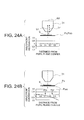
- FIG. 5A and FIG. 5B are diagrams showing the relationship between the sample position and the in-focus position, and the amount of wavefront aberration, where FIG.
- FIG. 5A is a diagram showing the relationship at the time of in-focus state
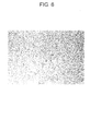
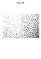
- FIG. 6 is an electronic image of the sample at the time of in-focus state.
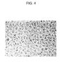
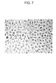
- Each electronic image in FIG. 3 , FIG. 4 , FIG. 6 and FIG. 7 is an image after executing the subtraction step S20.
- each sample in FIG. 3 , FIG. 4 , FIG. 6 and FIG. 7 is a cell.
- in-focus state means the state where the position of the sample S coincides with the in-focus position
- defocus state means the state where the sample S is displaced from the in-focus position.
- the direction of the displacement is in the upward direction for both of FIG. 2B and FiG.5B (the direction toward an image forming optical system 31).
- spatial frequency of the sample S is different between in FIG. 2A and FIG. 2B and in FIG. 5A and FIG.5B .
- the sample S shown in FIG. 2A and FIG. 2B , and the sample S shown in FIG. 5A and FIG. 5B are both the lattice-like phase object.
- spatial frequency is high (pitch of concavity and convexity of the phase is short) .
- spatial frequency is low compared with the sample S shown in FIG. 2A and FIG. 2B (pitch of concavity and convexity of the phase is long compared with the sample S shown in FIG. 2A and FIG. 2B ).
- the graphs represent an amount of wavefront aberration at the pupil position.
- the vertical axis of the graphs represents the amount of wavefront aberration (in the unit of wavelength), and the horizontal axis represents the distance from the center of the pupil plane (on the pupil plane). Since the distance from the center of the pupil plane is normalized, they are unitless numbers.
- the numerical value 0 on the horizontal axis represents the center position of the pupil plane, and 1 represents the outermost position of the pupil plane.
- light ray L C and light ray L P are included.
- the light ray L C travels along the optical axis.
- a point at the intersection of the light ray L C with the pupil plane coincides with the center position of the pupil plane.
- the light ray L P is a light ray which is incident on the image forming optical system 31 at a predetermined angle with respect to the optical axis AX.
- a point at the intersection of the light ray L P with the pupil plane coincides with a position away from the center of the pupil plane by a predetermined distance.
- zero-order diffracted light and first-order diffracted light emanate form the sample S.
- zero-order diffracted light can be considered as the light ray L C .
- first-order diffracted light is diffracted in a predetermined direction
- the first-order diffracted light emanated from this point is incident on the image forming optical system 31 at a predetermined angle with respect to the optical axis.
- the first-order diffracted light incident on the image forming optical system 31 reaches a position away from the center of the pupil plane. Therefore, first-order diffracted light can be considered as the light ray L P .
- the case where the sample S has a high spatial frequency is described below.
- the position P S of the sample S coincides with the in-focus position P F .
- an amount of wavefront aberration is 0 at any place on the pupil plane. This indicates that the amount of wavefront aberration in zero-order diffracted light and the amount of wavefront aberration in first-order diffracted light are both 0.
- a value obtained by multiplying the amount of wavefront aberration by (2 ⁇ / ⁇ ) is equivalent to the phase amount.
- a change in phase does not arise for both of the zero-order diffracted light and the first-order diffracted light.
- phase information cannot be obtained in the form of contrast information.
- the electronic image becomes an image without contrast.
- the position P S of the sample is displaced from the in-focus position P F .
- the position P S of the sample S is displaced upward (direction toward the image forming optical system 31) from the in-focus position P F .
- the wavefront aberration occurs at a position away from the center of the pupil.
- the wavefront aberration is a displacement of actual wavefront with reference to a reference wavefront, and this displacement is a displacement in phase.
- the phase of the first-order diffracted light is equivalent to a phase that the amount of wavefront aberration is added to the original phase of the first-order diffracted light.
- the amount of wavefront aberration at the position P W is - ⁇ /4. Therefore, the displacement ⁇ Z from the in-focus position P F is adjusted so that the position of the first-order diffracted light on the pupil plane coincides with the position P W . In other words, the displacement ⁇ Z is adjusted so that the amount of wavefront aberration is equivalent to - ⁇ /4 at the position of the first-order diffracted light on the pupil plane.
- the displacement ⁇ Z is adjusted so that the amount of wavefront aberration is equivalent to - ⁇ /4 at the position of the first-order diffracted light on the pupil plane.
- phase information can be obtained in the form of contrast information.
- the electronic image becomes an image with obvious contrast. Therefore, by displaying this electronic image on a display device, for example, an observer can observe the sample S (image of the sample S) clearly.
- the case where the sample S has a low spatial frequency is described below.
- the position P S of the sample S coincides with the in-focus position P F .
- the amount of wavefront aberration is 0 at any place on the pupil plane. This is the same as in FIG. 2A . Therefore, the electronic image becomes an image without contrast. However, for the reason as stated above, the electronic image becomes an image with a little bit of contrast as shown in FIG. 6 .
- the position P S of the sample S is displaced upward (direction toward the image forming optical system) from the in-focus position P F .
- the wavefront aberration occurs at a position away from the center of the pupil.
- a structure of the sample S shown in FIG. 5A and FIG. 5B is different from that of the sample S shown in FIG. 2A and FIG. 2B .
- the diffraction angle of the first-order diffracted light differs between FIG. 5B and FIG. 2B .
- the diffraction angle in FIG. 5B is smaller than that of FIG. 2B .
- the position of the first-order diffracted light at the pupil plane also differs between FIG. 5B and FIG. 2B .
- the position where the amount of wavefront aberration is equivalent to - ⁇ /4 becomes P W '.
- the position P W ' is closer to the center of the pupil plane than the position P W shown in FIG. 2B .
- the displacement ⁇ Z is adjusted so that the position of the first-order diffracted light on the pupil plane coincides with the position P W '.
- the displacement ⁇ Z is adjusted so that the amount of wavefront aberration is equivalent to - ⁇ /4 at the position of the first-order diffracted light on the pupil plane.
- FIG. 5B by setting the displacement ⁇ Z at 20 ⁇ m, the position of the first-order diffracted light on the pupil plane can coincide with the position P W '.
- the amount of wavefront aberration at the first diffracted light is - ⁇ /4.
- a relationship between the phase of zero-order diffracted light and the phase of first-order diffracted light is a relationship of opposite phase.
- the zero-order diffracted light and the first-order diffracted light are mutually weakened. Therefore, in the electronic image, brightness of the sample S becomes dark as compared with the background. This corresponds to dark contrast in phase-contract observation.
- diffraction angle of the diffracted light differs depending on the spatial frequency of the sample S. For instance, when the sample S is a lattice-like phase object, spacing of the lattice is wide means that a spatial frequency included in the sample S is low. On the other hand, spacing of the lattice is narrow means that a spatial frequency included in the sample S is high.
- spacing of the lattice becomes wide the diffraction angle becomes small, and the spacing of the lattice becomes narrow the diffraction angle becomes large. Therefore, when the sample S has a low spatial frequency, the diffraction angle is small, and when the sample S has a high spatial frequency, the diffraction angle is large.
- FIG. 4 is an electronic image by adjustment 1
- FIG. 7 is an electronic image by adjustment 2.
- the sample of FIG. 4 and the sample of FIG. 7 are the same.
- the inner region of cells (part having a low spatial frequency) is clear in the electronic image of FIG. 7 .
- the direction of the displacement may be in a downward direction (direction away from the image forming optical system 31).
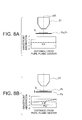
- FIG. 8A, FIG. 8B , FIG. 9A, and FIG.9B show such a state. Since detailed descriptions of FIG. 8A and FIG. 8B are the same as in FIG. 2A and FIG. 2B , and detailed descriptions of FIG. 9A and FIG.9B are the same as in FIG. 5A and FIG. 5B , they are omitted.
- the amount of wavefront aberration at the first-order diffracted light is + ⁇ /4.
- a relationship between the phase of zero-order diffracted light and the phase of first-order diffracted light is a relationship of same phase.
- the zero-order diffracted light and the first-order diffracted light are mutually strengthened. Therefore, in the electronic image, brightness of the sample S becomes bright as compared with the background. This corresponds to bright contrast in phase-contract observation.
- the diffraction angle of the first-order diffracted light is larger in FIG. 8B than in FIG. 9B . Therefore, while the outer region of cells (part having a high spatial frequency) is clear in the electronic image of FIG. 8B , the inner region of cells (part having a low spatial frequency) is clear in the electronic image of FIG. 9B .
- the displacement ⁇ Z is not so large. In this case, even if the sample S is displaced relative to the in-focus position, the position where the first-order diffracted light is incident on the image forming optical system 31 hardly changes. For this reason, a change of the position of the first-order diffracted light on the pupil plane also can be considered as slight. Therefore, the amount of wavefront aberration added to the first-order diffracted light can be set at - ⁇ /4 simply by moving the position of the sample S.
- the subtraction step S20 When the acquisition step S10 ends, the subtraction step S20 then is executed. At the subtraction step S20, a DC component (bias component) is subtracted from a signal of the electronic image.
- a 1 2 +A 2 2 represents the DC component (bias component) at the image of the sample, i.e., the DC component (bias component) of a signal of the electronic image.
- the amplitude A 1 2 of the zero-order diffracted light has a very large value. Therefore, at the subtraction step S20, the value of A 1 2 is made smaller. By doing so, it is possible to make the value of 2A 1 A 2 cos ⁇ relatively large with reference to the value of A 1 2 +A 2 2 . As a result, it is possible to observe the sample S (image of the sample S) clearly.
- the sample observation method of the second embodiment includes a comparison step after the subtraction step, and the acquisition step is performed at least three times, and an electronic image acquired earlier and an electronic image acquired later are compared at the comparison step, and the procedure from the acquisition step to the comparison step is repeated until an electronic image which satisfy a predetermined condition is acquired.
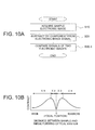
- FIG. 10A is a flowchart simply describing the sample observation method of the second embodiment
- FIG. 10B is a graph representing the relationship between the distance between the sample and the image forming optical system and the contrast.
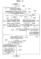
- FIG. 11 is a flowchart describing the sample observation method of the second embodiment in details.
- the sample observation method of the second embodiment includes a comparison step S30-1 in addition to the acquisition step S10 and the subtraction step S20.
- the comparisons step S30-1 is executed after the subtraction step S20.
- the acquisition step S10 is performed at least three times, and an electronic image acquired earlier and an electronic image acquired later are compared at the comparison step S30-1.
- the procedure from the acquisition step S10 to the comparison step S30-1 is performed repeatedly until an electronic image satisfying a predetermined condition is acquired. Accordingly, in the sample observation method of the second embodiment, it is possible to acquire a clearer electronic image automatically.
- Contrast is one of criteria to evaluate the quality of electronic images.
- the contrast changes with a distance between the sample S and the image forming optical system 31 (hereinafter, referred to as "distance D" as appropriate).
- distance D a distance between the sample S and the image forming optical system 31
- the contrast gradually increases in the section X1, and then in the section X2, the contrast gradually decreases.
- the contrast gradually increases, and in the section X4 the contrast gradually decreases.
- the distance D may be set at a distance having large contrast. That is, the distance D may be set at a distance at a boundary part between the section X1 and the section X2 (hereinafter, referred to as “distance DM1" as appropriate), or at a distance at a boundary part between the section X3 and the section X4 (hereinafter, referred to as “distance DM2" as appropriate).
- distance D1 the distance when an electronic image is acquired firstly (hereinafter, referred to as "distance D1" as appropriate) exists in what section among the sections X1 to X4.
- n (S300).
- the acquisition step S10 (first time) and the subtraction step S20 are executed.
- an electronic image is acquired with the distance D1.
- the number of acquisitions is determined (S301).
- the determination result at S301 is YES. Therefore, 1 is added to the variable n (S302), and the electronic image acquired is stored at a storage unit 1 (S303). Further, the distance (distance D) between the sample S and the image forming optical system 31 is widened by a predetermined amount (S304).
- the predetermined amount is assumed to be set beforehand.
- the acquisition step S10 is executed again (second time). At this time, an electronic image is acquired with a wider distance D than the distance D1. Then the subtraction step S20 is executed, and the number of acquisitions is determined (S301, S305).
- the value of the variable n is 1, the determination result at S301 is NO, and the determination result at S305 is YES. Therefore, 1 is added to the variable n (S306), and the electronic image acquired is stored at a storage unit 2 (S307).
- the distance D may be narrowed so as to increase the contrast. Therefore, setting is made to narrow the distance D (S309).
- the distance D may be narrowed by a predetermined amount as well at S309.
- the predetermined amount here may be the same amount as the predetermined amount at S304 or may be different.
- the determination result is NO, i.e., when contrast of the electronic image in the storage unit 1 ⁇ contrast of the electronic image in the storage unit 2, then the distance D1 exists in the section X2 or in the section X4.
- the distance D may be widened so as to increase the contrast. Therefore, setting is made to widen the distance D (S310). Although not shown in the flowchart, the distance D may be widened by a predetermined amount as well at S310. The predetermined amount here may be the same amount as the predetermined amount at S304 or may be different. Further, the electronic image stored in the storage unit 2 is stored in the storage unit 1 (S311). By doing so, the electronic image acquired earlier is stored in the storage unit 1.
- processing from S301 to S311 are included in comparison step S30-1, the processing from S301 to S311 may be performed only once. Therefore, even when the procedure from the acquisition step S10 to the comparison step S30-1 is repeated, the processing from S301 to S311 is not repeated.
- the acquisition step S10 is executed again (third time). At this time, an electronic image is acquired with a distance D that is widened or narrowed by a predetermined amount. Then the subtraction step S20 is executed, and the number of acquisitions is determined (S301, S305).
- the determination result at S301 is NO, and the determination result at S305 also is NO.
- the electronic image acquired is stored in the storage unit 2 (S312). By doing so, the electronic image acquired later is stored in the storage unit 2.
- the distance D is changed by a predetermined amount in accordance with the designated distance variation (S316).
- the designated distance variation means a variation to narrow the distance D (setting at S309) or a variation to widen the distance D (setting at S310).
- the processing is repeated until the determination result at S313 becomes YES. It is possible to acquire an electronic image with sufficiently high contrast automatically by executing such repeated processing. As a result, it is possible to observe the sample S (image of the sample S) more clearly.
- the predetermined condition is set as contrast of the electronic image in the storage unit 1 > contrast of the electronic image in the storage unit 2.
- the predetermined condition may be set so that a difference in contrast between two electronic images is smaller than a permissible value E as below,
- the electronic image acquired finally will be an image with the distance DM1.
- the electronic image acquired finally will be an image with the distance DM2.
- an electronic image with the distance DM2 may be acquired by adding another processing when the distance D1 exists in the section X1 or the section X2 as well.
- an electronic image with the distance DM1 may be acquired.
- the position of the sample S and the in-focus position of the image forming optical system 31 coincide during the processing.
- the acquisition step S10 is executed. Descriptions on the other processing are omitted.
- the sample observation method of the third embodiment includes an amplification step after the subtraction step, and at the amplification step, a signal of an electronic image subjected to the subtraction step is amplified.
- FIG. 12A is a flowchart of the sample observation method of the third embodiment and the sample observation method of the tenth embodiment described later.
- the sample observation method of the third embodiment includes an amplification step S30-2 in addition to the acquisition step S10 and the subtraction step S20. Accordingly, in the sample observation method of the third embodiment, it is possible to acquire a clearer electronic image.
- a 1 2 +A 2 2 represents the DC component of the sample image, i.e., the DC component of a signal of the electronic image.
- the value of A 1 2 is made smaller, whereby the value of 2A 1 A 2 cos ⁇ is made relatively large with reference to the value of A 1 2 +A 2 2 .
- the amplification step S30-2 is executed after the acquisition step S10 and the subtraction step S20 end.
- the value of 2A 1 A 2 cos ⁇ is made larger (amplified). By doing so, it is possible to make the value of 2A 1 A 2 cos ⁇ relatively large with reference to the value of A 1 2 +A 2 2 . As a result, it is possible to observe the sample S (image of the sample S) more clearly.
- the amplification step S30-2 may be used in the sample observation method of the second embodiment. In this case, the amplification step S30-2 is executed prior to the comparison step S30-1.
- a sample observation method of the fourth embodiment includes a conversion step of performing Fourier transform of a signal of an electronic image, and an inverse conversion step of performing inverse Fourier transform, and the conversion step is performed prior to the subtraction step, and the inverse conversion step is performed at least after the subtraction step.
- FIG. 12B is a flowchart of the sample observation method of the fourth embodiment and the sample observation method of the eleventh embodiment described later.
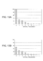
- FIG. 13A and FIG. 13B are diagrams showing the magnitude at each spatial frequency, where FIG. 13A is a diagrams showing the state before performing the subtraction step, and FIG. 13B is a diagrams showing the state after performing the subtraction step.
- the sample observation method of the fourth embodiment includes a conversion step S15-1 and an inverse conversion step S30-3 in addition to the acquisition step S10 and the subtraction step S20. Accordingly, in the sample observation method of the fourth embodiment, it is possible to acquire clearer electronic images easily.
- the value of A 1 2 is made smaller, whereby the value of 2A 1 A 2 cos ⁇ is made relatively large with reference to the value of A 1 2 +A 2 2 .
- the subtraction step S20 is executed at a frequency space, subtraction can be performed effectively.
- a sample such as cell includes a structure having various spatial frequencies. Therefore, if brightness of the image of the sample S can be separated for each spatial frequency, subtraction can be performed for each spatial frequency.
- the conversion step S15-1 is executed after the acquisition step S10 ends.
- Fourier transform is performed for a signal of an electronic image.
- the magnitude vertical axis, corresponding to brightness
- the numerical values on the horizontal axis represent spatial frequencies. At the spatial frequency is 0, the magnitude is 100, and at the spatial frequency is 1, the magnitude is 30.
- the values of spatial frequency correspond to the order of diffracted light. Therefore, the magnitude (numerical value on the vertical axis) at the spatial frequency of 0 corresponds to the brightness of zero-order diffracted light. Similarly, the magnitude at the spatial frequency of 1 corresponds to the brightness of first-order diffracted light.
- the subtraction step S20 is executed. At this subtraction step S20, the magnitude at the spatial frequency of 0 is made smaller. For instance, as shown in FIG. 13B , the magnitude at the spatial frequency of 0 is decreased to half from 100 to 50. This corresponds to that the value of A 1 2 is made smaller. By doing so, it is possible to make the brightness of zero-order light smaller.
- the inverse conversion step S30-3 is executed.
- inverse Fourier transform is performed. Accordingly, it is possible to acquire a signal of an electronic image.
- the brightness of zero-order light, i.e., the value of A 1 2 is made smaller at the subtraction step S20. Therefore, it is possible to make the value of 2A 1 A 2 cos ⁇ relatively large with reference to the value of A 1 2 +A 2 2 . As a result, it is possible to observe the sample S (image of the sample S) more clearly.
- the conversion step S15-1 and the inverse conversion step S30-3 may be used in the sample observation method of the second embodiment and the sample observation method of the third embodiment. In this case, the conversion step S15-1 is executed prior to the subtraction step S20. The inverse conversion step S30-3 is executed after the subtraction step S20.
- a sample observation method of the fifth embodiment includes an acquisition in advance step and a normalization step, and at the acquisition in advance step, an electronic image is acquired without a sample, and at the normalization step, using the electronic image, an electronic image of a sample is normalized, and the normalization step is performed prior to the subtraction step.
- FIG. 14 is a flowchart of the sample observation method of the fifth embodiment and the sample observation method of the twelfth embodiment described later.
- the sample observation method of the fifth embodiment includes an acquisition in advance step S00 and a normalization step S15-2 in addition to the acquisition step S10 and the subtraction step S20. Accordingly, in the sample observation method of the fifth embodiment, it is possible to acquire a clearer electronic image.
- the amplification step S30-2 is executed after the subtraction step S20, but amplification step S30-2 is not essential.
- Brightness of the image of the sample S may be affected by the illumination optical system or by the image forming optical system. For instance, when light passes through the illumination optical system or the image forming optical system, the light after passing therethrough generates unevenness in brightness. In this case, due to such unevenness in brightness of the illumination optical system or the image forming optical system, the unevenness in brightness is also generated in the image of the sample S. Since such unevenness in brightness will degrade the quality of an electronic image, it is preferable to remove such unevenness in brightness.
- the acquisition in advance step S00 is executed prior to the acquisition step S10.
- an electronic image A is acquired without a sample S.
- the electronic image A will be an image with unevenness in brightness only.
- the acquisition step S10 is executed, and thereby an electronic image B of the sample S is acquired.
- This electronic image B will be an image including unevenness in brightness due to the illumination optical system or the image forming optical system in addition to the image of the sample S. Therefore, the normalization step S15-2 is executed.
- the electronic image B is normalized with the electronic image A. More specifically, the following operation is executed at the normalization step S15-2:
- the unevenness in brightness at the electronic image B is canceled with the unevenness in brightness at the electronic image A. Therefore, the electronic image subjected to normalization becomes an image with reduced unevenness in brightness due to the illumination optical system or the image forming optical system.
- the subtraction step S20 is executed.
- the value of A 1 2 of an electronic image subjected to normalization is made small, and thereby the value of 2A 1 A 2 cos ⁇ is made relatively large with reference to the value of A 1 2 +A 2 2 .
- the sample S image of the sample S
- the acquisition in advance step S00 and the normalization step S15-2 may be used in any of the sample observation method of the second embodiment to the sample observation method of the fourth embodiment.
- the acquisition in advance step S00 is executed prior to the acquisition step S10.
- the normalization step S15-2 is executed prior to the subtraction step S20.
- the position of a sample is changed relative to the in-focus position of the image forming optical system a plurality of times, and at each position of the sample after changing, the acquisition step and the subtraction step are performed, and thereby a plurality of electronic images are generated after the subtraction step, and the plurality of electronic images generated are added.
- the sample observation method of the sixth embodiment at the time of generating an electronic image, an image with high contrast at each frequency space from a low frequency space to a high spatial frequency is used. Therefore, at the electronic image generated, the contrast becomes high at every spatial frequency. As a result, it is possible to observe the sample S (image of the sample S) clearly.
- a part with highest contrast in each of a plurality of electronic images is extracted, and the addition is performed using the extracted parts.
- the sample observation method of the seventh embodiment at the time of generating an electronic image by addition, a part with highest contrast only for each frequency space is used. Therefore, at the electronic image generated, the contrast becomes very high at every spatial frequency. As a result, it is possible to observe the sample S (image of the sample S) can be observed more clearly.
- a change of the position of the sample is made while keeping the sign of the amount of wavefront aberration in the first predetermined state same.
- the electronic image when the amount of wavefront aberration at the first-order diffracted light is - ⁇ /4, the electronic image will be a dark contrast image. More specifically, in the electronic image, an image of the sample S becomes dark as compared with the background. On the other hand, when the amount of wavefront aberration at the first-order diffracted light is + ⁇ /4, the electronic image will be a bright contrast image. More specifically, in the electronic image, an image of the sample S becomes bright as compared with the background.
- a sample observation device of the present embodiment is described below.
- a sample observation device from the first embodiment to the third embodiment includes a light source, an illumination optical system, an image forming optical system, an image-pickup device, and an image processing device, and the illumination optical system is disposed so as to irradiate a sample with illumination light from the light source, and the image forming optical system is disposed so that light from the sample is incident thereon and an optical image of the sample is formed, and the image-pickup device is disposed at the position of the optical image, and the image processing device is configured to implement the sample observation methods from the first embodiment to the eighth embodiment as stated above.
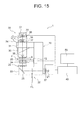
- the configuration of the sample observation device of the first embodiment is shown in FIG. 15 .
- the sample observation device 1 is an observation system based on an upright microscope.
- the sample observation device 1 includes a main-body part 10, an illumination part 20, an observation part 30, and an image processing device 40.
- the illumination part 20 and the observation part 30 are attached to the main-body part 10.
- the main-body part 10 and the image processing device 40 are connected in a wired or wireless manner.
- the sample observation device 1 may include a display device 50.
- the display device 50 may be connected to the image processing device 40 in a wired or wireless manner.
- the main-body part 10 includes a stage 11.
- the stage 11 is a holding member. On this stage 11, a sample S is held. Movement of the sample S is performed using a manipulation knob (not shown) and a focusing knob (not shown) attached to the stage. Through the manipulation of the manipulation knob, the sample S is moved in a plane perpendicular to the optical axis. Through the manipulation of the focusing knob, the sample S is moved along the optical axis.
- the illumination part 20 includes a light source 21 and an illumination optical system 22.
- the illumination optical system 22 includes a condenser lens 23 and an aperture stop 24. As shown in FIG. 15 , the illumination optical system 22 may include a lens 25, a mirror 26, and a lens 27. In FIG. 15 , the condenser lens 23 and the aperture stop 24 are held at the stage 11.
- the illumination optical system 22 is disposed in an optical path from the light source 21 to the stage 11.
- the observation part 30 includes an image forming optical system 31 and an image-pickup device 32.
- the observation part 30 may include a revolver 33 and an observation lens barrel 34.
- the image forming optical system 31 includes a microscope objective lens 35 (hereinafter, referred to as "objective lens 35") and an image-pickup lens 36.
- objective lens 35 a microscope objective lens 35
- the image forming optical system 31 may include an image forming lens 37 and a prism 38.
- the image forming optical system 31 is disposed in an optical path from the stage 11 to the image-pickup device 32.
- the image-pickup device 32 includes an image-pickup element 39.
- the illumination part 20 is disposed on the side opposed to the observation part 30 across the stage 11. Therefore, in the sample observation device 1, the sample S is illuminated with transmitted illumination.
- Illumination light emanates from the light source 21.
- the illumination light passes through the illumination optical system 22 and reaches the stage 11.
- the sample S is illuminated with this illumination light.
- the light from the sample S is collected by the image forming optical system 31, and thereby an image of the sample S (optical image) is formed at the light-collection position.
- the image-pickup element 39 of the image-pickup device 32 picks up an image of the sample S.
- the image of the sample S is converted into an electronic image (digital data) through the image pickup.
- the electronic image is sent to the image processing device 40.
- various types of processing are performed.
- the sample observation device 1 includes the display device 50
- the electronic image is displayed on the display device 50.
- an observer can observe the sample S (image of the sample S).
- the image-pickup device 32 may include a circuit for automatic gain control. By doing so, it is possible to make the brightness (contrast) of the electronic image picked up constant.
- the image processing device 40 may include such a circuit for automatic gain control.
- sample observation method of one embodiment is described using the sample observation device 1.
- sample observation method of the first embodiment is used as an example.
- a white light source is used as the light source 21.
- an observer sets the illumination optical system 22 and the image forming optical system 31 in the state of a bright-field observation.
- the observer places the sample S on the stage 11.
- the observer moves the sample by eye to the position where the observer thinks that it is displaced from the in-focus position. Accordingly, the position of the sample S and the in-focus position are made to be different in the state of bright-field observation.
- the image processing device 40 is activated. These steps may be performed in random order.
- the sample observation device is ready to pick up an image of the sample S, and so the acquisition step S10 is executed.
- the acquisition step S10 is executed, an electronic image is acquired.
- the electronic image acquired at the acquisitions step S10 is stored in a temporary storage unit (not shown) in the image processing device 40.
- the subtraction step S20 is executed.
- the value of A 1 2 is made to be small, the value of 2A 1 A 2 cos ⁇ becomes relatively large with reference to the value of A 1 2 +A 2 2 .
- the execution result at the subtraction step S20 is displayed on the display device 50, for example.
- the position of the sample S is set by eye.
- the image of the sample S is defocused greatly. Therefore, even when the image of the sample S is picked up, the observer cannot observe an electronic image thereof on the display device 50.
- the observer manipulates the focusing knob to move the sample S toward the in-focus position. If the sample S is far away from the objective lens 35, the observer may move the stage 11 so as to move the sample S toward the objective lens 35. On the other hand, when the sample S is very close to the objective lens 35, the observer may move the stage 11 so as to move the sample S away the objective lens 35.
- the acquisition step S10 and the subtraction step S20 also are continuously executed. Then, the observer can move the sample S along the optical axis while viewing an electronic image on the display device 50, and stops to move the sample S when an electronic image with good contrast can be acquired. As a result, it is possible to observe the sample S (image of the sample S) clearly.
- the main-body part 10 may include a motor 12.
- the motor 12 is connected to the stage 11. It is possible to move the sample S by moving the stage 11 along the optical axis using the motor 12.
- the sample observation device of the first embodiment it is possible to observe a colorless and transparent sample clearly in the state of bright-field observation as well.
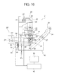
- the configuration of the sample observation device of the second embodiment is shown in FIG. 16 .
- the sample observation device 1' is an observation system based on an inverted microscope.
- the same reference numerals are assigned to the same components as those of the sample observation device 1, and their descriptions are omitted.
- the sample observation device 1' in the of the sample observation device 1', illumination part 20 is disposed on the side opposed to the observation part 30 across the stage 11. Therefore, in the sample observation device 1' as well, the sample S is illuminated with transmitted illumination. However, the sample observation device 1' then includes an illumination part 20' in addition to the illumination part 20. The illumination part 20' is disposed on the same side as the observation part 30. Therefore, in the sample observation device 1' , it is possible to illuminate the sample S by epi-illumination using the illumination part 20'.
- the illumination part 20' includes a light source 21' and an illumination optical system 22'.
- the illumination optical system 22' includes a condenser lens and an aperture stop.
- illumination is performed through the objective lens 35. Therefore, the objective lens 35 corresponds to a condenser lens.
- the aperture stop is not shown in the drawing.
- the illumination optical system 22' may include a lens 25' , a half mirror HM and a lens 27'.
- the illumination optical system 22' is disposed in an optical path from the light source 21' to the stage 11.
- the half mirror HM and the objective lens 35 make up the illumination optical system 22' as well as the image forming optical system 31.
- the image-pickup element 39 of the image-pickup device 32 picks up an image of the sample S.
- the prism 38 is moved out of the optical path of the image forming optical system 31, light of the sample S can be guided to an eyepiece of the observation lens barrel 34. In this case, light of the sample S is reflected toward the observation lens barrel 34 by the mirror M.
- the motor 12 is connected to the revolver 33. Therefore, in the sample observation device 1', the revolver 33 is moved along the optical axis by the motor 12. As the revolver 33 moves along the optical axis, the objective lens 35 (image forming optical system 31) moves along the optical axis. Accordingly, it is possible to make in a state where the position of the sample S and the in-focus position are different.
- the sample observation device 1' it is possible to illuminate the sample S by transmitted illumination or vertical illumination.
- the vertical illumination is described below.
- illumination light emanates from the light source 21'.
- the illumination light passes through the illumination optical system 22' and reaches the stage 11.
- the sample S is illuminated with this illumination light.
- the light from the sample S is collected by the image forming optical system 31, and thereby an image of the sample S (optical image) is formed at the light-collection position.
- the prism 38 is disposed in the optical path of the image forming optical system 31, the image-pickup element 39 of the image-pickup device 32 picks up an image of the sample S.
- the image of the sample S is converted into an electronic image (digital data) through the image pickup.
- the electronic image is sent to the image processing device 40.
- various types of processing are performed.
- the sample observation device 1 includes the display device 50
- the electronic image is displayed on the display device 50.
- an observer can observe the sample S (image of the sample S) clearly.
- sample observation method of one embodiment is described using the sample observation device 1'.
- sample observation method of the second embodiment is used as an example.
- a white light source is used as the light source 21'.
- an observer sets the illumination optical system 22' and the image forming optical system 31 in the state of a bright-field observation. Then the observer places the sample S on the stage 11. Next the image processing device 40 is activated. These steps may be performed in random order.
- the observer inputs information of observation starting to the image processing device 40.
- information of displacement from the in-focus position is assumed to be stored in the image processing device 40 beforehand.
- the image processing device 40 calculates the amount of movement based on the current position of the revolver 33 (microscope objective lens 35) and the displacement from the in-focus position. Based on the calculation result, the image processing device 40 transmits a driving signal to the motor 12. Based on the signal transmitted, the motor 12 moves the revolver 33 so that the sample S is displaced from the in-focus position. In this way, it is possible to make in a state where the position of the sample S and the in-focus position are different.
- the acquisition step S10 (first time) is executed. Then an electronic image is acquired.
- the electronic image acquired is stored in a temporary storage unit (not illustrated) in the image processing device 40.
- the subtraction step S20 is executed. After the subtraction step S20 ends, the electronic image is stored in a storage unit 1 (not shown) in the image processing device 40.
- the electronic image stored in the storage unit 1 is displayed on the display device 50, for example.
- the image processing device 40 transmits a driving signal to the motor 12.
- the driving signal at this time is to widen the distance D (distance between the sample S and the objective lens 35) by a predetermined amount.
- the motor 12 moves the revolver 33 in accordance with the signal so that the objective lens 35 is moved away from the stage 11.
- the acquisition step S10 (second time) and the subtraction step S20 are executed. After the subtraction step S20 ends, the electronic image is stored in a storage unit 2 (not shown) in the image processing device 40.
- the acquisition step S10 (third time) and the subtraction step S20 are executed.
- comparison of contrast is made between the electronic image in the storage unit 1 and the electronic image in the storage unit 2.
- the procedure from the acquisition step S10 to the comparison step 30-1 is repeated until a predetermined condition is satisfied.
- the sample observation device of the second embodiment it is possible to observe a colorless and transparent sample more clearly in the state of bright-field observation as well.
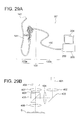
- FIG. 17A is a diagram showing the schematic configuration of the observation device
- FIG. 17B is a diagram showing the configuration of the optical system.
- a sample observation device 300 is an observation system based on an electronic endoscope.
- the sample observation device 300 includes an electronic endoscope 100 and an image processing device 200.
- the electronic endoscope 100 includes a scope part 100a and a connection cord part 100b.
- the image processing device 200 is connected to a display unit 204.
- the scope part 100a is roughly divided into a manipulation part 140 and an insertion part 141.
- the insertion part 141 is long and thin and so is able to be inserted into a body cavity of a patient.
- the insertion part 141 is made of a member having flexibility. An observer can perform various manipulations using an angle knob, for example, provided at the manipulation part 140.
- connection cord part 100b is extended.
- the connection cord part 100b includes a universal cord 150.
- the universal cord 150 is connected to the image processing device 200 via a connector 250.
- the universal cord 150 is used to exchange various types of signals.
- a power-supply voltage signal, a CCD driving signal and the like are included in the various types of signals. These signals are transmitted from a power-supply device or a video processor to the scope part 100a.
- a video signal is included in the various types of signals. This signal is transmitted from the scope part 100a to a video processor.
- the video processor in the image processing device 200 can be connected to peripheral devices such as a VTR deck and a video printer, which are not shown.
- the video processor performs signal processing of a video signal from the scope part 100a. Based on the video signal, an endoscopic image is displayed on a display screen of a display unit 204.
- an optical system is disposed in a forward end part 142 of the insertion part 141.
- the electronic endoscope 100 is a magnifying endoscope. Therefore, the optical system is configured to form a magnified image of the sample S. Tissues in body are object to be observed in an endoscope. In the following descriptions, the tissues in body are assumed to be included in the sample S as well.
- An illumination part includes a light source and an illumination optical system. Light from the light source emanates from an optical fiber 401.
- the illumination optical system includes a lens 402, a mirror 403, a lens 404, a half prism 405, and an objective lens 406.
- An observation part includes an image forming optical system and an image-pickup device.
- the image forming optical system includes the objective lens 406, the half prism 405, and an image forming lens 407.
- the image-pickup device includes an image-pickup element 408. In this optical system, a sample S is illuminated with epi-illumination.
- sample observation method of one embodiment is described using the sample observation device 300.
- sample observation method of the third embodiment is used as an example.
- a white light source is used as the light source.
- an observer sets the illumination optical system and the image forming optical system in the state of a bright-field observation. Then the observer moves the insertion part 141 by eye to the position where the observer thinks that it is displaced from the in-focus position. Next, the image processing device 200 is activated. These processing steps may be performed in random order.
- the sample observation device is ready to pick up an image of the sample S, and so the acquisition step S10 is executed.
- the acquisition step S10 is executed, an electronic image is acquired.
- the electronic image acquired at the acquisitions step S10 is stored in a temporary storage unit (not shown) in the image processing device 200.
- the subtraction step S20 is executed.
- the value of A 1 2 is made to be small, the value of 2A 1 A 2 cos ⁇ becomes relatively large with reference to the value of A 1 2 +A 2 2 .
- the amplification step S30-2 is executed.
- the value of 2A 1 A 2 cos ⁇ is made larger (amplified). Accordingly, the value of 2A 1 A 2 cos ⁇ becomes relatively larger with reference to the value of A 1 2 +A 2 2 .
- the execution result at the amplification step S30-2 is displayed on the display device 204, for example.
- the acquisition step S10, the subtraction step S20 and the amplification step S30-2 also are continuously executed. Then the observer can move the insertion part 141 while viewing an electronic image on the display device 204, and stops to move the insertion part 141 when an electronic image with good contrast can be acquired. As a result, it is possible to observe the sample S (image of the sample S) clearly.
- At least one of the objective lens 406, the image-pickup lens 407 and the image-pickup element 408 may be moved along the optical axis. They may be moved using a micro-actuator (not illustrated) or a voice coil motor (not illustrated). By, doing so, it is possible to adjust the displacement ⁇ Z finely. Therefore, the movement of the insertion part 141 can be stopped when an electronic image with certain contrast is acquired.
- the sample observation device of the third embodiment it is possible to observe a colorless and transparent sample more clearly in the state of bright-field observation as well.
- NA ill denotes a numerical aperture of the illumination optical system on the sample side
- NA ob denotes a numerical aperture of the image forming optical system on the sample side
- the numerical aperture of the illumination optical system on the sample side is too small. In this case, insufficiency of light amount of the illumination light becomes large or unevenness of the illumination becomes large. Moreover, on the electronic image, dirt or foreign particles on the cover glass becomes conspicuous.
- FIG. 18A, FIG. 18B, and FIG. 18C are diagrams showing a relationship between the incident direction of illumination light and the diffraction direction of diffracted light, and the wavefront aberration, where FIG. 18A is a diagram showing the case where the illumination light is incident in parallel with the optical axis, FIG. 18B is a diagram showing the case where the angle between the incident direction of the illumination light and the optical axis is small, and FIG. 18C is a diagram showing the case where the angle between the incident direction of the illumination light and the optical axis is large.
- Diffracted light generated from the sample S depends on an incident direction of the illumination light on the sample S.
- an incident direction of a illumination light L ill is parallel to the optical axis
- zero-order diffracted light L 0 travels along the optical axis and reaches the pupil position.
- +1 for first order diffracted light L +1 is incident on the image forming optical system at the angle + ⁇ with respect to the optical axis and reaches the pupil position.
- -1 for first order diffracted light L -1 is incident on the image forming optical system at the angle - ⁇ with respect to the optical axis and reaches the pupil position.
- a diffraction directions of the +1 for first order diffracted light L +1 and the -1 for first order diffracted light L -1 are symmetrical across the optical axis, and the wavefront aberration also occurs symmetrically with respect to the center (optical axis) of the pupil plane. Therefore, the amount of wavefront aberration added to the +1 for first order diffracted light L +1 and the amount of wavefront aberration added to the -1 for first order diffracted light L -1 become same.
- phase information can be obtained in the form of contrast information.
- the contrast acquired is so-called dark contrast.
- the angle between the incident direction of the illumination light L ill and the optical axis is small (the angle is ⁇ )
- the zero-order diffracted light L 0 travels in the same direction as the incident direction of the illumination light L ill . Therefore, the zero-order diffracted light L 0 is incident on the image forming optical system at the angle of + ⁇ with respect to the optical axis, and reaches the pupil position.
- +1 for first order diffracted light L +1 is diffracted outside (direction away from the optical axis) of a predetermined direction.
- +1 for first order diffracted light L +1 is incident on the image forming optical system at the angle of +2 ⁇ with respect to the optical axis, and reaches the pupil position.
- -1 for first order diffracted light L -1 also is diffracted, the -1 for first order diffracted light L -1 travels along the optical axis and reaches the pupil position.
- the wavefront aberration occurs symmetrically with respect to the center (optical axis) of the pupil plane. Therefore, the amount of wavefront aberration added to the zero-order diffracted light L 0 , the amount of wavefront aberration added to the +1 for first order diffracted light L +1 , and the amount of wavefront aberration added to the -1 for first order diffracted light L -1 are mutually different.
- the amount of wavefront aberration of - ⁇ /4 is added to the zero-order diffracted light L 0
- the amount of wavefront aberration of -3 ⁇ /4 is added to the +1 for first order diffracted light L +1 .
- the amount of wavefront aberration added to the -1 for first order diffracted light L -1 becomes 0.
- phase of the zero-order diffracted light L 0 is delayed by ⁇ /2.
- the delay will be 2 ⁇ in total.
- phase information can be obtained in the form of contrast information.
- the contrast acquired is so-called bright contrast.
- the zero-order diffracted light L 0 travels in the same direction as the incident direction of the illumination light L ill . Therefore, the zero-order diffracted light L 0 is incident on the image forming optical system at the angle of +2 ⁇ with respect to the optical axis, and reaches the pupil position.
- +1 for first order diffracted light L +1 is diffracted outside of an effective aperture of the image forming optical system. That is, the +1 for first order diffracted light L +1 does not reach the pupil position.
- the -1 for first order diffracted light L -1 is incident on the image forming optical system at the angle of + ⁇ with respect to the optical axis, and reaches the pupil position.
- the wavefront aberration occurs symmetrically with respect to the center (optical axis) of the pupil plane. Therefore, the amount of wavefront aberration added to the zero-order diffracted light L 0 and the amount of wavefront aberration added to the -1 for first order diffracted light L -1 are mutually different.
- the amount of wavefront aberration of -3 ⁇ /4 is added to the zero-order diffracted light L 0
- the amount of wavefront aberration of - ⁇ /4 is added to the -1 for first order diffracted light L -1 .
- phase information cannot be obtained in the form of contrast information.
- the incident direction of the illumination light L ill is parallel to the optical axis. More specifically, it becomes the state shown in FIG. 18A . Therefore, an image of a point on the optical axis can be observed in a so-called dark contrast. Meanwhile, as the numerical aperture of the illumination optical system on the sample side increases, illumination light L ill whose incident direction intersects with the optical axis is applied as shown in FIG. 18B and FIG. 18C .
- conditional expression (1') is satisfied instead of the conditional expression (1): 0.02 ⁇ NA ill / NA ob ⁇ 0.9
- conditional expression (1") is satisfied instead of the conditional expression (1): 0.03 ⁇ NA ill / NA ob ⁇ 0.8
- conditional expression (2) 0.1 ⁇ m ⁇ ⁇ Z ⁇ NA ob 2 ⁇ 30 ⁇ m
- ⁇ Z denotes a difference in position between the in-focus position of the image forming optical system and the sample
- NA ob denotes the numerical aperture of the image forming optical system on the sample side.
- the difference between the in-focus position of the image forming optical system and the position of the sample is too large.
- the amount of wavefront aberration added to the diffracted light is large.
- the amount of wavefront aberration added to the first-order diffracted light becomes larger than ⁇ /4.
- an optical image is defocused greatly. As a result, it becomes difficult to acquire an electronic image with high resolution.
- conditional expression (2') is satisfied instead of the conditional expression (2): 0.2 ⁇ m ⁇ ⁇ Z ⁇ NA ob 2 ⁇ 25 ⁇ m
- conditional expression (2" is satisfied instead of the conditional expression (2): 0.3 ⁇ m ⁇ ⁇ Z ⁇ NA ob 2 ⁇ 20 ⁇ m
- conditional expression (3) 0.05 ⁇ m ⁇ ⁇ Z ⁇ NA ill ⁇ 10 ⁇ m where ⁇ Z denotes the difference in position between the in-focus position of the image forming optical system and the sample, and NA ill denotes the numerical aperture of the illumination optical system on the sample side.
- the difference between the in-focus position of the image forming optical system and the position of the sample is too large.
- the amount of wavefront aberration added to the diffracted light is large.
- the amount of wavefront aberration added to the first-order diffracted light becomes larger than ⁇ /4.
- an optical image is defocused greatly.
- the numerical aperture of the illumination optical system on the sample side is too large. In this case, illumination light obliquely incident with respect to the optical axis increases. Therefore, it becomes difficult to acquire an electronic image with good contrast.
- conditional expression (3') is satisfied instead of the conditional expression (3): 0.1 ⁇ m ⁇ ⁇ Z ⁇ NA ill ⁇ 8 ⁇ m
- conditional expression (3") is satisfied instead of the conditional expression (3): 0.2 ⁇ m ⁇ ⁇ Z ⁇ NA ill ⁇ 6 ⁇ m
- the illumination optical system includes a condenser lens and an aperture stop.
- the illumination optical system is a Kohler illumination optical system.
- the illumination optical system is a telecentric optical system.
- FIG. 19 is a diagram showing a case where the illumination optical system is a telecentric optical system.
- the illumination optical system includes a condenser lens 62 and an aperture stop 60. At a front focal plane 61 of the condenser lens 62, the aperture stop 60 is disposed. Therefore, axial light flux (line indicated with the solid line) emanated from the center of the aperture stop 60 is converted into parallel light flux by the condenser lens 62, and reaches a position 63 of the sample. Meanwhile, off-axis light flux (line indicated with broke lines) emanated from the periphery of the aperture stop 60 also is converted into parallel light flux by the condenser lens 62, and reaches the position 63 of the sample.
- the illumination optical system is a telecentric optical system, the off-axis light flux is incident on the condenser lens so that its principal ray is parallel to the optical axis.
- the light flux passing through the center of the aperture stop 60 is converted into parallel to the optical axis and reaches the position of the sample.
- the sample is illuminated with light flux that is parallel to the optical axis, and then zero-order diffracted light and first-order diffracted light are generated from the sample. Between them, zero-order diffracted light travels in parallel with the optical axis.
- +1 for first order diffracted light and -1 for first order diffracted light travel in the direction away from the optical axis.
- the +1 for first order diffracted light and the -1 for first order diffracted light travel while being symmetrical with respect to the optical axis.
- the amount of wavefront aberration added to the +1 for first order diffracted light and the amount of wavefront aberration added to the -1 for first order diffracted light become both same.
- the zero-order diffracted light and the +1 for first order diffracted light are mutually weakened, then the zero-order diffracted light and the -1 for first order diffracted light also are mutually weakened.
- each sample observation device of the embodiments as stated above includes wavelength selection means.
- illumination light is monochromatic light.
- aberrations of the image forming optical system are small.
- the amount of generation of wavefront aberration differs with the wavelength. For instance, when the sample is illuminated with white light, the amount of wavefront aberration added to the first-order diffracted light may be 1/4 ⁇ for light at a certain wavelength and may be -1/4 ⁇ for light at another wavelength.
- an image has dark contrast for light at a certain wavelength and has bright contrast for light at another wavelength. Therefore, considering the white light as a whole, it becomes difficult to acquire an electronic image with good contrast.
- the sample observation device includes wavelength selection means, it is possible to suppress the decrease of contrast.
- the sample observation device including wavelength selection means it is possible to eliminate variations in the amount of generation of wavefront aberration due to wavelength. For this reason, it is possible to acquire an electronic image with good contrast.
- the image forming optical system which has large axial chromatic aberration is used, it is possible to acquire an electronic image with good contrast by including wavelength selection means. The same applies to the case where the illumination light is monochromatic light.
- the illumination light and the image forming light may have light of a common wavelength. Therefore, in the sample observation device 1 ( FIG. 15 ), an arrangement is made such that an optical filter FL (wavelength selection means) can be disposed in the optical path of the illumination part 20. Moreover, in the sample observation device 1' ( FIG. 16 ), an arrangement is made such that an optical filter FL and an optical filter FL' (not shown) can be disposed alternately in the optical path of the image forming optical system 31. Although no optical filter FL is shown, in the sample observation device 300 ( FIG. 17A, FIG. 17B ),it is possible to have a similar configuration to those of the sample observation device 1 and the sample observation device 1'.
- an optical filter FL wavelength selection means
- the optical filter FL may be movable. Moreover, number of the optical filter FL is not limited to one. A plurality of optical filters FL may be prepared, each having different spectral transmission property, and one or a plurality of them may be disposed in the optical path.
- the optical filter FL may be disposed at any one of the illumination optical system and the image forming optical system, or at both of them.
- the optical filter FL may be disposed at the image-pickup device. When the image-pickup device includes any optical filter, then this optical filter may be used.
- the optical filter FL has a property of transmitting light of long wavelengths, by using such an optical filter FL it is possible to reduce damages on cells.
- the optical filter FL has a property of transmitting light of short wavelengths, by using such an optical filter FL it is possible to acquire an electronic image with high resolution.
- the light source itself may be used a light source which emit light of a narrow wavelength band. By doing so, it is possible to eliminate the necessity to dispose an optical filter in the optical path of the optical system. Moreover, a plurality of light sources may be used.
- the image forming optical system is a telecentric optical system.
- the image forming optical system includes an aperture stop. Moreover, in each sample observation devices of the embodiments as stated above, it is preferable that the image forming optical system includes an objective lens, and the aperture stop is disposed at the objective lens.
- FIG. 20 is a diagram showing the wavefront aberration at two objective lenses each having different numerical aperture (NA) .
- NA numerical aperture
- the curve shown in solid line and the curve shown in dotted lines both indicate the relationship between numerical aperture and the amount of wavefront aberration.
- the solid line indicates the amount of wavefront aberration at an objective lens having a large numerical aperture (hereinafter, referred to as “objective lens OB 1 " as appropriate).
- the dotted lines indicate the amount of wavefront aberration at an objective lens having a small numerical aperture (hereinafter, referred to as "objective lens OB 2 " as appropriate).
- the objective lens OB 1 and the objective lens OB 2 have the amount of wavefront aberration of - ⁇ /4 at the position where the numerical aperture of both is 0.2. Therefore, it is possible to acquire an electronic image with good contrast by letting the position of the first-order diffracted light coincide with the position having the numerical aperture of 0. 2.
- the numerical aperture of the objective lens OB 1 is large. Therefore, higher-order diffracted light than the first-order diffracted light will be incident on the objective lens OB 1 .
- the amount of wavefront aberration is added to the higher-order diffracted light as well. Therefore, zero-order diffracted light and the higher-order diffracted light may be mutually weakened or strengthened depending on the magnitude of the amount of wavefront aberration. As a result, it becomes difficult to acquire an electronic image with good contrast at the objective lens OB 1 .
- the aperture stop in the objective lens OB 1 , it is possible to control the numerical aperture of the objective lens OB 1 . More specifically, the numerical aperture of the objective lens OB 1 can be made the same degree as that of the numerical aperture of the objective lens OB 2 . As a result, it is possible to acquire an electronic image with good contrast.
- the aperture stop may be disposed at any position as long as the numerical aperture can be limited at a position from the objective lens to the image-pickup device. Therefore, the image forming optical system may include the aperture stop.
- the objective lens may be an endoscopic objective lens, in addition to the objective lens.
- NA im is a value obtained by dividing the numerical aperture of the image forming optical system on the sample side by a projection magnification of the image forming optical system.
- the Nyquist frequency of the image-pickup element greatly falls below the cut-off frequency of the image forming optical system (e.g., objective lens). Therefore, the quality of an electronic image is degraded.
- the electronic image has the number of pixels that is more than the one required. Therefore, it is difficult to handle such an electronic image.
- each sample observation device of the embodiments as stated above includes a driving mechanism, and the driving mechanism moves at least one of the holding member, the image-pickup device and the image forming optical system along the optical axis.
- the image forming optical system and the image-pickup element are preferably moved.
- the sample S can be in a static state. Therefore, when the sample has a very soft structure or the object to be observed floats in the liquid as well, it is possible to acquire an electronic image without changing the state of the sample (without deforming the shape or changing the position in the liquid).
- sample observation methods from the ninth embodiment to the fifteenth embodiment and the sample observation devices from the fourth embodiment to the sixth embodiment are used in the state of bright-field observation.
- the fluorescent mirror unit including the excitation filter, the dichroic mirror, and the absorption filter, which is used in the fluorescent observation is not used. Therefore, in the state of bright-field observation, when the sample is colorless and transparent, light forming an image of the sample (hereinafter, referred to as "image forming light” as appropriate) has the wavelength band that coincides with the wavelength band of light for illumination of the sample (hereinafter, referred to as "illumination light” as appropriate) at the time of in-focusing.
- phase film which is used in the phase-contrast observation
- differential interference prism which is used in the differential interference observation
- a neutral density filter which is for partially dimming of light flux from the sample, is not used. Therefore, in the state of bright-field observation, a change of intensity in the image forming light does not arise from the sample to the image of the sample (excluding a change in intensity resulting from a lens).
- a sample observation method of the ninth embodiment includes an acquisition step of acquiring an electronic image of a sample, and a subtraction step of subtracting a DC component from a signal of the electronic image, and the acquisition step is performed in the state of bright-field observation, and the electronic image at the subtraction step is an image acquired in a second predetermined state, and before reaching the second predetermined state, the position of the sample and the in-focus position of the image forming optical system are made to be coincident using light of a first wavelength band, and in the second predetermined state, an optical image of the sample is formed using a second wavelength band at least, and the second wavelength band is coincident with a part of the first wavelength band, or is different from the first wavelength band.
- FIG. 1 is a flowchart of the sample observation method of the ninth embodiment.
- the sample observation method of the ninth embodiment includes an acquisition step S10 and a subtraction step S20. Accordingly, in the sample observation method of the ninth embodiment, it is possible to acquire a clear electronic image.
- the acquisition step S10 is executed firstly.
- an electronic image of the sample is acquired.
- the image of the sample (optical image) is formed by the image forming optical system.
- the image of the sample is picked up by an image-pickup element, such as a CCD or a CMOS.
- the image of the sample is converted into an electronic image (digital data) through the image pickup. Since the image of the sample is formed in the state of bright-field observation, an acquisition of the electronic image also is performed in the state of bright-field observation.
- the electronic image of the sample is referred to as "electronic image" as appropriate.
- the subtraction step S20 is executed.
- a DC component bias component
- the electronic image at the subtraction step S20 is an image acquired in a second predetermined state.
- the electronic image at the subtraction step S20 is an image in the second predetermined state, i.e., when an optical image of the sample is formed using the light of the second wavelength band.
- the position of the sample and the in-focus position of the image forming optical system are made to be coincident using the light of the first wavelength band.
- the second wavelength band coincides with a part of the first wavelength band, or is different from the first wavelength band.
- the wavelength band of light is different between before acquisition of an electronic image and at a time of acquisition of the electronic image (moment).
- the in-focus position of the image forming optical system is referred "in-focus position" as appropriate.
- the sample is a lattice-like phase object
- the image forming optical system has axial chromatic aberration to some extent
- the wavelength band of light is made to be different between before acquisition of an electronic image and at a time of acquisition of the electronic image.
- a difference in wavefront aberration difference in optical path length
- first-order diffracted light is used as the diffracted light.
- the image forming optical system is assumed to have axial chromatic aberration to some extent.
- Each electronic image in FIG. 22 , FIG. 23 , FIG. 25 and FIG. 26 is an image after executing the subtraction step S20.
- each sample in FIG. 22 , FIG. 23 , FIG. 25 and FIG. 26 is a cell.
- the graphs represent the amount of wavefront aberration at the pupil position.
- the vertical axis of the graphs represents the amount of wavefront aberration (in the unit of wavelength), and the horizontal axis represents the distance from the center of the pupil plane (on the pupil plane). Since the distance from the center of the pupil plane is normalized, they are unitless numbers.
- the numerical value 0 on the horizontal axis represents the center position of the pupil plane, and 1 represents the outermost position of the pupil plane.
- light emanated from one point on the optical axis includes light ray L C and light ray L P .
- the light ray L C travels along the optical axis.
- a point at the intersection of the light ray L C with the pupil plane coincides with the center position of the pupil plane.
- the light ray L P is incident on the image forming optical system 31 at a predetermined angle with respect to the optical axis AX.
- a point at intersection between the light ray L P with the pupil plane coincides with a position away from the center of the pupil plane by a predetermined distance.
- zero-order diffracted light and first-order diffracted light emanate form the sample S.
- zero-order diffracted light can be considered as the light ray L C .
- first-order diffracted light is diffracted in a predetermined direction
- the first-order diffracted light emanated from this point is incident on the image forming optical system 31 at a predetermined angle with respect to the optical axis.
- the first-order diffracted light incident on the image forming optical system 31 reaches a position away from the center of the pupil plane. Therefore, first-order diffracted light can be considered as the light ray L P .
- the center wavelength ⁇ 1 of the first wavelength band is 550 nm
- the center wavelength ⁇ 2 of the second wavelength band is 450 nm
- the in-focus position P 550 of the first wavelength band coincides with the position P S of the sample S.
- the amount of wavefront aberration is substantially 0 at any position of the pupil plane. This indicates that the amount of wavefront aberration in the zero-order diffracted light and the amount of wavefront aberration in the first-order diffracted light both are substantially 0.
- the in-focus position of the second wavelength band is displaced from the position of the sample.
- the in-focus position P 450 of the second wavelength band is displaced downward (direction away from the image forming optical system 31) from the position P S (in-focus position P 550 ) of the sample S.
- the wavefront aberration occurs at a position away from the center of the pupil plane.
- the wavefront aberration denotes a displacement of actual wavefront with reference to a reference wavefront, and this displacement denotes a displacement of phase.
- the phase of the first-order diffracted light is equivalent to a phase that the amount of wavefront aberration is added to a phase which the first-order diffracted light has originally.
- the wavelength band of light can be different between before acquisition of an electronic image and at a time of acquisition of the electronic image.
- the phase of the first-order diffracted light can be changed. As shown in the graph of FIG. 21B , when the position P W is set at a position where a distance from the pupil center is 0.4, the amount of wavefront aberration at the position P W is - ⁇ /4.
- phase information can be obtained in the form of contrast information.
- the electronic image becomes an image with obvious contrast.
- This electronic image may be displayed on a display device, for example, whereby an observer can observe the sample S (image of the sample S) clearly.
- the center wavelength ⁇ 1 of the first wavelength band is 550 nm
- the center wavelength ⁇ 2 of the second wavelength band is 650 nm
- the in-focus position P 650 of the second wavelength band is displaced downward (direction away from the image forming optical system 31) from the position P S (in-focus position P 550 ) of the sample S.
- the in-focus position P 650 is different from the in-focus position P 450 .
- the amount of wavefront aberration at the position of the first-order diffracted light on the pupil plane is different between FIG. 24B and FIG. 21B .
- the amount of wavefront aberration is about -1 ⁇ /10 at the position P W where a distance from the pupil center is 0.4.
- the amount of wavefront aberration at the first-order diffracted light can be - ⁇ /10 while keeping the amount of wavefront aberration at the zero-order diffracted light 0.
- the amount of wavefront aberration is different, this is the same state as in FIG. 21B . Therefore, as shown in FIG. 26 , the electronic image becomes image with obvious contrast. An observer so can observe the sample S (image of the sample S) clearly.
- the amount of wavefront aberration at the first diffracted light is - ⁇ /4.
- a relationship between the phase of zero-order diffracted light and the phase of first-order diffracted light is a relationship of opposite phase.
- the zero-order diffracted light and the first-order diffracted light are mutually weakened. Therefore, in the electronic image, brightness of the sample S becomes dark as compared with the background. This corresponds to dark contrast in phase-contract observation.
- diffraction angle of the diffracted light differs depending on the spatial frequency of the sample S. For instance, when the sample S is a lattice-like phase object, spacing of the lattice is wide means that a spatial frequency included in the sample S is low. On the other hand, spacing of the lattice is narrow means that a spatial frequency included in the sample S is high.
- spacing of the lattice becomes wider the diffraction angle becomes small, and the spacing of the lattice becomes narrower the diffraction angle becomes large. Therefore, when the sample S has a low spatial frequency, the diffraction angle is small, and when the sample S has a high spatial frequency, the diffraction angle is large.
- the second wavelength band When the second wavelength band is set so that the amount of wavefront aberration becomes - ⁇ /4 at a position of the first-order diffracted light at high spatial frequency, in the electronic image, a part having the high spatial frequency will be clear.
- the second wavelength band is set so that the amount of wavefront aberration becomes - ⁇ /4 at a position of the first-order diffracted light at low spatial frequency, in the electronic image, a part having the low spatial frequency will be clear.
- the in-focus position at the second wavelength band may be displaced upward from the position (in-focus position of the first wavelength band) of the sample S.
- the center wavelength ⁇ 1 of the first wavelength band may be 650 nm
- the center wavelength ⁇ 2 of the second wavelength band may be 550 nm.
- a difference in center wavelength is not so large between the first wavelength band and the second wavelength band.
- the incident position of the first-order diffracted light hardly changes with respect to the image forming optical system 31.
- a change of the position of the first-order diffracted light on the pupil plane also can be considered as slight. Therefore, it is possible to change the amount of wavefront aberration added to the first-order diffracted light simply by changing the wavelength band.
- the wavelength band of light is different between before acquisition of an electronic image and at a time of acquisition of the electronic image. Therefore, 2A 1 A 2 cos ⁇ 0 holds.
- a 1 2 +A 2 2 represents the DC component (bias component) at the image of the sample, i.e., the DC component (bias component) of a signal of the electronic image.
- the amplitude A1 2 of the zero-order diffracted light has a very large value. Therefore, at the subtraction step S20, the value of A 1 2 is made smaller. By doing so, it is possible to make the value of 2A 1 A 2 cosy ⁇ relatively large with reference to the value of A 1 2 +A 2 2 . As a result, it is possible to observe the sample S (image of the sample S) clearly.
- the sample observation method of the tenth embodiment includes an amplification step after the subtraction step, and at the amplification step, a signal of an electronic image subjected to the subtraction step is amplified.
- FIG. 12A is a flowchart of the sample observation method of the tenth embodiment.
- the sample observation method of the tenth embodiment includes an amplification step S30-2 in addition to the acquisition step S10 and the subtraction step S20. Accordingly, in the sample observation method of the tenth embodiment, it is possible to acquire a clearer electronic image.
- a 1 2 +A 2 2 represents the DC component of the sample image, i.e., the DC component of a signal of the electronic image.
- the value of A 12 is made smaller, whereby the value of 2A 1 A 2 cosy ⁇ is made relatively large with reference to the value of A1 2 +A 2 2 .
- the amplification step S30-2 is executed after the acquisition step S10 and the subtraction step S20 end.
- the value of 2A 1 A 2 cos ⁇ is made larger (amplified). By doing so, it is possible to make the value of 2A 1 A 2 cos ⁇ relatively large with reference to the value of A1 2 +A 2 2 . As a result, it is possible to observe the sample S (image of the sample S) more clearly.
- the amplification step S30-2 may be used in the sample observation method of the ninth embodiment. In this case, the amplification step S30-2 is executed prior to the comparison step S30-1.
- a sample observation method of the eleventh embodiment includes a conversion step of performing Fourier transform of a signal of an electronic image, and an inverse conversion step of performing inverse Fourier transform, and the conversion step is performed prior to the subtraction step, and the inverse conversion step is performed at least after the subtraction step.
- FIG. 12B is a flowchart of the sample observation method of the eleventh embodiment.
- FIG. 13A and FIG. 13B are diagrams showing the magnitude at each spatial frequency, where FIG. 13A is a diagrams showing the state before performing the subtraction step, and FIG. 13B s a diagrams showing the state after performing the subtraction step.
- the sample observation method of the eleventh embodiment includes a conversion step S15-1 and an inverse conversion step S30-3 in addition to the acquisition step S10 and the subtraction step S20. Accordingly, in the sample observation method of the eleventh embodiment, it is possible to acquire clearer electronic images easily.
- the value of A 1 2 is made smaller, whereby the value of 2A 1 A 2 cosy ⁇ is made relatively large with reference to the value of A1 2 +A 2 2 .
- the subtraction step S20 is executed at a frequency space, subtraction can be performed effectively.
- a sample such as cell includes a structure having various spatial frequencies. Therefore, if brightness of the image of the sample S can be separated for each spatial frequency, subtraction can be performed for each spatial frequency.
- the conversion step S15-1 is executed after the acquisition step S10 ends.
- Fourier transform is performed for a signal of an electronic image.
- the magnitude vertical axis, corresponding to brightness
- the numerical values on the horizontal axis represent spatial frequencies. At the spatial frequency is 0, the magnitude is 100, and at the spatial frequency is 1, the magnitude is 30.
- the values of spatial frequency correspond to the order of diffracted light. Therefore, the magnitude (numerical value on the vertical axis) at the spatial frequency of 0 corresponds to the brightness of zero-order diffracted light. Similarly, the magnitude at the spatial frequency of 1 corresponds to the brightness of first-order diffracted light.
- the subtraction step S20 is executed. At this subtraction step S20, the magnitude at the spatial frequency of 0 is made smaller. For instance, as shown in FIG. 13B , the magnitude at the spatial frequency of 0 is decreased to half from 100 to 50. This corresponds to that the value of A 1 2 is smaller. By doing so, it is possible to make the brightness of zero-order light smaller.
- the inverse conversion step S30-3 is executed.
- inverse Fourier transform is performed. Accordingly, it is possible to acquire a signal of an electronic image.
- the brightness of zero-order light, i.e., the value of A 1 2 is made smaller at the subtraction step S20. Therefore, it is possible to make the value of 2A 1 A 2 cos ⁇ relatively large with reference to the value of A1 2 +A 2 2 . As a result, it is possible to observe the sample S (image of the sample S) more clearly.
- the conversion step S15-1 and the inverse conversion step S30-3 may be used in the sample observation method of the tenth embodiment. In this case, the conversion step S15-1 is executed prior to the subtraction step S20. The inverse conversion step S30-3 is executed after the subtraction step S20.
- a sample observation method of the twelfth embodiment includes an acquisition in advance step and a normalization step, and at the acquisition in advance step, an electronic image is acquired without a sample, and at the normalization step, using the electronic image, an electronic image of a sample is normalized, and the normalization step is performed prior to the subtraction step.
- FIG. 14 is a flowchart of the sample observation method of the twelfth embodiment.
- the sample observation method of the twelfth embodiment includes an acquisition in advance step S00 and a normalization step S15-2 in addition to the acquisition step S10 and the subtraction step S20. Accordingly, in the sample observation method of the twelfth embodiment, it is possible to acquire a clearer electronic image.
- the amplification step S30-2 is executed after the subtraction step S20, but amplification step S30-2 is not essential.
- Brightness of the image of the sample S may be affected by the illumination optical system or by the image forming optical system. For instance, when light passes through the illumination optical system or the image forming optical system, the light after passing therethrough generates unevenness in brightness. In this case, due to such unevenness in brightness of the illumination optical system or the image forming optical system, the unevenness in brightness is also generated in the image of the sample S. Since such unevenness in brightness will degrade the quality of an electronic image, it is preferable to remove such unevenness in brightness.
- the acquisition in advance step S00 is executed prior to the acquisition step S10.
- an electronic image A is acquired without a sample S.
- the electronic image A will be an image with unevenness in brightness only.
- the acquisition step S10 is executed, and thereby an electronic image B of the sample S is acquired.
- This electronic image B will be an image including unevenness in brightness due to the illumination optical system or the image forming optical system in addition to the image of the sample S. Therefore, the normalization step S15-2 is executed.
- the electronic image B is normalized with the electronic image A. More specifically, the following operation is executed at the normalization step S15-2:
- the unevenness in brightness at the electronic image B is canceled with the unevenness in brightness at the electronic image A. Therefore, the electronic image subjected to normalization becomes an image with reduced unevenness in brightness due to the illumination optical system or the image forming optical system.
- the subtraction step S20 is executed.
- the value of A 1 2 of an electronic image subjected to normalization is made small, and thereby the value of 2A 1 A 2 cos ⁇ is made relatively large with reference to the value of A 1 2 +A 2 2 .
- the sample S image of the sample S
- the acquisition in advance step S00 and the normalization step S15-2 may be used in the sample observation method of the tenth embodiment and the sample observation method of the eleventh embodiment.
- the acquisition in advance step S00 is executed prior to the acquisition step S10.
- the normalization step S15-2 is executed prior to the subtraction step S20.
- the second wavelength band is changed with reference to the first wavelength band a plurality of times, and at each second wavelength band after changing, the acquisition step and the subtraction step are performed, and thereby a plurality of electronic images are generated after the subtraction step, and the plurality of electronic images generated are added.
- the sample observation method of the thirteenth embodiment at the time of generating an electronic image, an image with high contrast at each frequency space from a low frequency space to a high spatial frequency is used. Therefore, at the electronic image generated, the contrast becomes high at every spatial frequency. As a result, it is possible to observe the sample S (image of the sample S) clearly.
- a part with highest contrast in each of a plurality of electronic images is extracted, and the addition is performed using the extracted parts.
- the sample observation method of the fourteenth embodiment at the time of generating an electronic image by addition, a part with highest contrast only for each frequency space is used. Therefore, at the electronic image generated, the contrast becomes very high at every spatial frequency. As a result, it is possible to observe the sample S (image of the sample S) more clearly.
- a change of the second wavelength band is made while keeping the sign of the amount of wavefront aberration in the second predetermined state same.
- the electronic image when the amount of wavefront aberration at the first-order diffracted light is - ⁇ /4, the electronic image will be a dark contrast image. More specifically, in the electronic image, an image of the sample S becomes dark as compared with the background. On the other hand, when the amount of wavefront aberration at the first-order diffracted light is + ⁇ /4, the electronic image will be a bright contrast image. More specifically, in the electronic image, an image of the sample S becomes bright as compared with the background.
- a sample observation device of the present embodiment is described below.
- a sample observation device from the fourth embodiment to the sixth embodiment includes a light source, an illumination optical system, an image forming optical system, an image-pickup device, and an image processing device, and the illumination optical system is disposed so as to irradiate a sample with illumination light from the light source, and the image forming optical system is disposed so that light from the sample is incident thereon and an optical image of the sample is formed, and the image-pickup device is disposed at the position of the optical image, and the image processing device is configured to implement the sample observation methods from the ninth embodiment to the fifteenth embodiment as stated above.
- the configuration of the sample observation device of the fourth embodiment is shown in FIG. 27 .
- the sample observation device 2 is an observation system base on an upright microscope.
- the same reference numerals are assigned to the same components as those of the sample observation device 1, and their descriptions are omitted.
- an illumination part 20 includes a light source 21 and an illumination optical system 22.
- the illumination optical system 22 includes a condenser lens 23, an aperture stop 24, and an optical filter FL.
- the illumination optical system 22 may include a lens 25, a mirror 26 and a lens 27.
- the condenser lens 23 and the aperture stop 24 are held at a stage 11.
- the illumination optical system 22 is disposed in an optical path from the light source 21 to the stage 11.
- sample observation method of one embodiment is described using the sample observation device 2.
- sample observation method of the ninth embodiment is used as an example.
- a white light source is used as the light source 21.
- an observer sets the illumination optical system 22 and the image forming optical system 31 in the state of a bright-field observation.
- the observer places the sample S on the stage 11.
- the observer moves the sample by eye to the position where the observer thinks that it is displaced from the in-focus position. Accordingly, the position of the sample S and the in-focus position are made to be different in the state of bright-field observation.
- the image processing device 40 is activated. These steps may be performed in random order.
- the sample observation device is ready to pick up an image of the sample S, and so the acquisition step S10 is executed.
- the acquisition step S10 is executed, an electronic image is acquired.
- the electronic image acquired at the acquisitions step S10 is stored in a temporary storage unit (not shown) in the image processing device 40.
- the subtraction step S20 is executed.
- the value of A 1 2 is made to be small, the value of 2A 1 A 2 cos ⁇ becomes relatively large with reference to the value of A 1 2 +A 2 2 .
- the execution result at the subtraction step S20 is displayed on the display device 50, for example.
- the position of the sample S is set by eye.
- the image of the sample S is defocused greatly. Therefore, even when the image of the sample S is picked up, the observer cannot observe an electronic image thereof on the display device 50.
- the observer manipulates the focusing knob to move the sample S toward the in-focus position. If the sample S is far away from the objective lens 35, the observer may move the stage 11 so as to move the sample S toward the objective lens 35. On the other hand, when the sample S is very close to the objective lens 35, the observer may move the stage 11 so as to move the sample S away the objective lens 35.
- the acquisition step S10 and the subtraction step S20 also are continuously executed. Then, the observer can move the sample S along the optical axis while viewing an electronic image on the display device 50 so as to let the position of the sample S coincides with the in-focus position.
- the sample S is illuminated with white light (light of the first wavelength band).
- the in-focus position at this time can be considered as a position where focusing is established with green light (light with wavelength of 500 nm to 560 nm).
- an optical filter FL is inserted in the optical path of the illumination optical system 22.
- a wavelength band (transmission property) of the optical filter FL is assumed that the center wavelength is 450 nm and the wavelength width is ⁇ 20 nm.
- the wavelength band of the optical filter FL coincides with a part of the wavelength band of white light.
- the wavelength band of light is made to be different between before acquisition of an electronic image and at a time of acquisition of the electronic image (moment). As a result, it is possible to observe the sample S (image of the sample S) clearly.
- the sample observation device of the fourth embodiment it is possible to observe a colorless and transparent sample clearly in the state of bright-field observation as well.
- the configuration of the sample observation device of the fifth embodiment is shown in FIG. 28 .
- the sample observation device 2' is an observation system based on an inverted microscope.
- the same reference numerals are assigned to the same components as those of the sample observation device 1', and their descriptions are omitted.
- the image forming optical system 31 includes optical filter FL and optical filter FL'.
- the optical filter FL is disposed in the optical path of the image forming optical system 31.
- the optical filter FL' is disposed outside of the optical path of the image forming optical system 31.
- the optical filter FL and the optical filter FL' can be exchanged.
- sample observation method of one embodiment is described using the sample observation device 2'.
- sample observation method of the ninth embodiment is used as an example.
- a white light source is used as the light source 21'.
- an observer sets the illumination optical system 22' and the image forming optical system 31' in the state of a bright-field observation. Then the observer places the sample S on the stage 11.
- an optical filter LF is inserted in the optical path of the image forming optical system 31.
- a wavelength band (transmission property) of the optical filter FL is assumed that the center wavelength is 550 nm and the wavelength width is ⁇ 20 nm.
- the image processing device 40 is activated. These steps may be performed in random order.
- the observer inputs information of observation starting to the image processing device 40.
- information of the in-focus position is assumed to be stored in the image processing device 40 beforehand.
- the image processing device 40 calculates the amount of movement based on the current position of the revolver 33 (microscope objective lens 35) and the information on the in-focus position. Based on the calculation result, the image processing device 40 transmits a driving signal to the motor 12. Based on the signal transmitted, the motor 12 moves the revolver 33 so that the position of the sample S coincides with the in-focus position.
- the in-focus position at this time can be considered as the position where focusing is established using the light having the wavelength band of 550 nm ⁇ 20 nm (light of the first wavelength band).
- the optical filter FL is taken out of the optical path of the image forming optical system 31, and instead the optical filter FL' is inserted.
- a wavelength band (transmission property) of the optical filter FL' is assumed that the center wavelength is 650 nm and the wavelength width is ⁇ 20 nm. In this case, the wavelength band of the optical filter FL' is different from the wavelength band of the optical filter FL.
- the wavelength band of light is made to be different between before acquisition of an electronic image and at a time of acquisition of the electronic image (moment). As a result, it is possible to observe the sample S (image of the sample S) clearly.
- a wavelength-variable interference filter can be used as the optical filter FL.
- the wavelength-variable interference filter is an optical filter whose wavelength band (transmission property) can be changed. By using the wavelength-variable interference filter, it is possible to eliminate the necessity of exchanging the optical filter FL and the optical filter FL'.
- the sample observation method may be configured as follows.
- the sample is illuminated with white light (light of the first wavelength band) and the position of the sample S is allowed to coincide with the in-focus position.
- the optical filter FL is inserted in the optical path of the image forming optical system 31.
- an optical image of the sample is formed using the light of the second wavelength band.
- the wavelength band of the optical filter FL is different from the wavelength band of the optical filter FL' of white light. Therefore, the wavelength band of light is made to be different between before acquisition of an electronic image and at a time of acquisition of the electronic image (moment). As a result, it is possible to observe the sample S (image of the sample S) clearly.
- the sample observation method may be configured as follows.
- the optical filter FL is inserted in the optical path of the illumination optical system 22, and the position of the sample S is allowed to coincide with the in-focus position. Then, the optical filter FL is taken out of the optical path of the illumination optical system 22, and instead an optical filter FL' is inserted in the optical path of the image forming optical system 31.
- an optical image of the sample is formed using the light of the second wavelength band.
- the wavelength band of the optical filter FL is different from the wavelength band of the optical filter FL'. Therefore, the wavelength band of light is made to be different between before acquisition of an electronic image and at a time of acquisition of the electronic image (moment). As a result, it is possible to observe the sample S (image of the sample S) clearly.
- the sample observation device of the fifth embodiment it is possible to observe a colorless and transparent sample more clearly in the state of bright-field observation as well.
- FIG. 29A and FIG. 297B The configuration of a sample observation device of the sixth embodiment is shown in FIG. 29A and FIG. 297B.
- a sample observation device 301 is an observation system based on an electronic endoscope.
- FIG. 29A is a diagram showing the schematic configuration of the observation device
- FIG. 29B is a diagram showing the configuration of the optical system.
- the same reference numerals are assigned to the same components as those of the sample observation device 300, and their descriptions are omitted.
- an illumination part includes a light source and an illumination optical system. Light from the light source emanates from an optical fiber 401.
- the illumination optical system includes a lens 402, a mirror 403, a lens 404, a half prism 405 and an objective lens 406.
- An observation part includes an image forming optical system and an image-pickup device.
- the image forming optical system includes the objective lens 406, the half prism 405, an image forming lens 407, and an optical filter 409.
- the image-pickup device includes an image-pickup element 408. In this optical system, a sample S is illuminated with epi-illumination.
- sample observation method of one embodiment is described using the sample observation device 301.
- sample observation method of the eleventh embodiment is used as an example.
- a white light source is used as the light source.
- an observer sets the illumination optical system and the image forming optical system in the state of a bright-field observation. Then the observer moves the insertion part 141 by eye to the position where the observer thinks it as the in-focus position. Next, the image processing device 200 is activated. These processing steps may be performed in random order.
- the sample observation device is ready to pick up an image of the sample S, and so the acquisition step S10 is executed.
- the acquisition step S10 is executed, an electronic image is acquired.
- the electronic image acquired at the acquisitions step S10 is stored in a temporary storage unit (not shown) in the image processing device 200.
- the subtraction step S20 is executed.
- the value of A 1 2 is made to be small, the value of 2A 1 A 2 cos ⁇ becomes relatively large with reference to the value of A 1 2 +A 2 2 .
- the amplification step S30-2 is executed.
- the value of 2A 1 A 2 cos ⁇ is made larger (amplified). Accordingly, the value of 2A 1 A 2 cos ⁇ becomes relatively larger with reference to the value of A 1 2 +A 2 2 .
- the execution result at the amplification step S30-2 is displayed on the display device 204, for example.
- the acquisition step S10, the subtraction step S20 and the amplification step S30-2 also are continuously executed. Then the observer can move the insertion part 141 while viewing an electronic image on the display device 204 so as to let the position of the sample S coincide with the in-focus position.
- the sample S is illuminated with white light (light of the first wavelength band).
- the in-focus position at this time can be considered as a position where focusing is established with green light (light with wavelength of 500 nm to 560 nm).
- an optical filter FL is inserted in the optical path of the illumination optical system 22.
- a wavelength band (transmission property) of the optical filter FL is assumed that the center wavelength is 650 nm and the wavelength width is ⁇ 20 nm.
- the wavelength band of the optical filter FL coincides with a part of the wavelength band of white light.
- the wavelength band of light is made to be different between before acquisition of an electronic image and at a time of acquisition of the electronic image (moment). As a result, it is possible to observe the sample S (image of the sample S) clearly.
- At least one of the objective lens 406, the image-pickup lens 407 and the image-pickup element 408 may be moved along the optical axis.
- a micro-actuator (not shown) or a voice coil motor (not shown) may be used to move them. By doing so, it is possible to adjust the in-focus state finely. Therefore, the movement of the insertion part 141 can be stopped when an electronic image of contrast to certain extent is acquired.
- the sample observation device of the sixth embodiment it is possible to observe a colorless and transparent sample more clearly in the state of bright-field observation as well.
- conditional expression (5) is satisfied preferably: 10 ⁇ m ⁇ d / NA ob 2 ⁇ 1000 ⁇ m
- d denotes an amount of axial chromatic aberration of the second wavelength band with reference to the first wavelength band
- NA ob denotes the numerical aperture of the image forming optical system on the sample side.
- the difference in the amount of wavefront aberration between at the first wavelength band and at the second wavelength band is too large.
- the amount of wavefront aberration added to the diffracted light is large.
- the amount of wavefront aberration added to the first-order diffracted light becomes larger than ⁇ /4.
- an optical image is defocused greatly. As a result, it becomes difficult to acquire an electronic image with high resolution.
- the image forming optical system includes an objective lens, and the axial chromatic aberration at the objective lens changes monotonously with wavelength.
- the image-pickup device includes an image-pickup element, and in the image-pickup device, a minute optical filter having a different wavelength band is displaced for each pixel.
- an optical filter is disposed.
- This optical filter includes a plurality of minute optical filters. These minute optical filters include red filters, green filters and blue filters, for example. Further, a plurality of minute optical filters are disposed in each color.
- an image signal may be extracted from these color filters for each color, whereby an optical image can be taken easily using light of the second wavelength band. That is, there is no need to dispose an optical filter in the optical path of the illumination optical system and the optical path of the image forming optical system.
- the image-pickup element may be a monochrome image-pickup element.
- the present invention may have various modification examples without departing from the gist of the invention.
- the present invention is suitable to a sample observation method and a sample observation device enabling observation of a colorless and transparent sample, such as cells, in the state of bright-field observation as well.
Landscapes
- Physics & Mathematics (AREA)
- General Physics & Mathematics (AREA)
- Optics & Photonics (AREA)
- Engineering & Computer Science (AREA)
- Multimedia (AREA)
- Chemical & Material Sciences (AREA)
- Analytical Chemistry (AREA)
- Computer Vision & Pattern Recognition (AREA)
- Signal Processing (AREA)
- Microscoopes, Condenser (AREA)
Abstract
Description
- The present invention relates to sample observation methods and sample observation devices.
- When a sample is illuminated with parallel light flux, non-diffracted light (hereinafter, referred to as "zero-order diffracted light") and diffracted light are generated from a sample. In microscopes, an image of a sample is formed by synthesis of zero-order diffracted light and diffracted light.
- Complex amplitude E at the image plane is represented by the following expression, for example:

Where
A1 denotes an amplitude of zero-order diffracted light,
A2 denotes an amplitude of diffracted light,
φ1 (r) denotes a phase of zero-order diffracted light, and
φ2(r) denotes a phase of diffracted light. - Since intensity of light is observed at the image plane, the intensity I of light at the image plane can be represented by the following expression:

where
ψ denotes a phase difference, and ψ=φ1(r)-φ2(r). - As described above, zero-order diffracted light and diffracted light is necessary for forming the image (optical image) of the sample. Therefore, in the following description, an image (optical image) of a sample is assumed to be formed by zero-order diffracted light and first-order diffracted light. Since the phase of first-order diffracted light delays π/2 relative to the phase of zero-order diffracted light, the phase difference is expressed by ψ=0-(-π/2)=π/2. In this case, since 2A1A2cosψ=0, phase information cannot be obtained in the form of contrast information. As a result, in attempting to observe an image of a colorless and transparent sample, e.g., cells, at an in-focus position, it is very difficult to observe the image of the cell in a bright-field observation.
- A phase-contrast observation is one method to observe the colorless and transparent sample. In the phase-contrast observation, a phase-contrast microscope is used. Various proposals have been made for a phase-contrast microscope. A microscope, which makes an observation of the sample at a position displaced from the in-focus position of an image forming optical system so as to observe an image (phase-contrast image) in a wide observation field, is one available microscope. The microscope disclosed in
Japanese Patent Application Laid-open Publication No. 2005-173288 JP 2005-173288 A - When the sample is displaced from the in-focus position of the image forming optical system, a difference in optical path length (phase difference) occurs between zero-order diffracted light and diffracted light. In this case, since 2A1A2cosψ≠0, then phase information can be obtained in the form of contrast information. The value of A1 2, however, is very large as compared with the value of 2A1A2cosψ. Therefore, in the microscope of
JP 2005-173288 A - In the microscope of
JP 2005-173288 A - The present invention has been accomplished in view of the foregoing, and an object of the present invention is to provide a sample observation method and a sample observation device enabling observation of a colorless and transparent sample, such as cells, in the state of bright-field observation as well.
- In order to solve the above-described problems and achieve the object,
a sample observation method of the present invention comprises: - an acquisition step of acquiring an electronic image of a sample, and
- a subtraction step of subtracting a DC component from a signal of the electronic image,
wherein - the acquisition step is performed in a state of bright-field observation,
- the electronic image at the subtraction step is an image acquired in a first predetermined state, and
- in the first predetermined state, at least a position of the sample and a in-focus position of an image forming optical system are different.
- Another sample observation method of the present invention comprises:
- an acquisition step of acquiring an electronic image of a sample, and
- a subtraction step of subtracting a DC component from a signal of the electronic image,
wherein
the acquisition step is performed in a state of bright-field observation,
the electronic image at the subtraction step is an image acquired in a second predetermined state,
before reaching the second predetermined state, a position of the sample and an in-focus position of an image forming optical system are made to be coincident using light of a first wavelength band, - in the second predetermined state, an optical image of the sample is formed using light of a second wavelength band at least, and
- the second wavelength band is coincident with a part of the first wavelength band, or is different from the first wavelength band.
- A sample observation device of the present invention comprises:
- a light source,
- an illumination optical system,
- an image forming optical system,
- an image-pickup device, and
- an image processing device,
wherein
the illumination optical system is disposed so as to irradiate a sample with illumination light from the light source,
the image forming optical system is disposed so that light from the sample is incident thereon and an optical image of the sample is formed,
the image-pickup device is disposed at a position of the optical image, and
the image processing device is configured to implement the sample observation method as stated above. - According to the present invention, it is possible to provide a sample observation method and a sample observation device enabling observation of a colorless and transparent sample, such as cells, in the state of bright-field observation as well.
-
-
FIG. 1 is a flowchart of sample observation method of a first embodiment and a ninth embodiment. -
FIG. 2A and FIG. 2B are diagrams showing relationship between sample position and in-focus position, and an amount of wavefront aberration, whereFIG. 2A is a diagram showing the relationship at a time of in-focus state, andFIG. 2B is a diagram showing the relationship at a time of defocus state (displacement ΔZ=10 µm). -
FIG. 3 is an electronic image of the sample at the time of in-focus state. -
FIG. 4 is an electronic image of the sample at the time of defocus state (displacement ΔZ=10 µm). -
FIG. 5A and FIG. 5B are diagrams showing the relationship between the sample position and the in-focus position, and the amount of wavefront aberration, whereFIG. 5A is a diagram showing the relationship at the time of in-focus state, andFIG. 5B is a diagram showing the relationship at the time of defocus state (displacement ΔZ=20 µm). -
FIG. 6 is an electronic image of the sample at the time of in-focus state. -
FIG. 7 is an electronic image of the sample at the time of defocus state (displacement ΔZ=20 µm). -
FIG. 8A and FIG. 8B are diagrams showing the relationship between the sample position and the in-focus position, and the amount of wavefront aberration, whereFIG. 8A is a diagram showing the relationship at the time of in-focus state, andFIG. 8B is a diagram showing the relationship at the time of defocus state (displacement ΔZ=10 µm). -
FIG. 9A and FIG. 9B are diagrams showing the relationship between the sample position and the in-focus position, and the amount of wavefront aberration, whereFIG. 9A is a diagram showing the relationship at the time of in-focus state, andFIG. 9B is a diagram showing the relationship at the time of defocus state (displacement ΔZ=20 µm). -
FIG. 10A and FIG. 10B are diagrams showing a sample observation method of the second embodiment, whereFIG. 10A is a flowchart simply describing the sample observation method andFIG. 10B is a graph representing a relationship between the distance between the sample and the image forming optical system and the contrast. -
FIG. 11 is a flowchart describing the sample observation method of the second embodiment in details. -
FIG. 12A and FIG. 12B are flowcharts of the sample observation methods as embodiments, whereFIG. 12A is a flowchart of the sample observation method of the third embodiment and the tenth embodiment, andFIG. 12B is a flowchart of the sample observation method of the fourth embodiment and the eleventh embodiment. -
FIG. 13A and FIG. 13B are diagrams showing the magnitude at each spatial frequency, whereFIG. 13A is a diagram showing the state before performing the subtraction step, andFIG. 13B is a diagram showing the state after performing the subtraction step. -
FIG. 14 is a flowchart of the sample observation method of the fifth embodiment and the twelfth embodiment. -
FIG. 15 is a diagram showing a configuration of the sample observation device of the first embodiment. -
FIG. 16 is a diagram showing a configuration of the sample observation device of the second embodiment. -
FIG. 17A and FIG. 17B are diagrams showing a configuration of a sample observation device of the third embodiment, whereFIG. 17A is a diagram showing the schematic configuration of the sample observation device schematically, andFIG. 17B is a diagram showing the configuration of the optical system. -
FIG. 18A, FIG. 18B, and FIG. 18C are diagrams showing a relationship between the incident direction of illumination light and the diffraction direction of diffracted light, and the wavefront aberration, whereFIG. 18A is a diagram showing a case where the illumination light is incident in parallel with the optical axis,FIG. 18B is a diagram showing a case where the angle between the incident direction of the illumination light and the optical axis is small, andFIG. 18C is a diagram showing a case where the angle between the incident direction of the illumination light and the optical axis is large. -
FIG. 19 is a diagram showing a case where the illumination optical system is a telecentric optical system. -
FIG. 20 is a diagram showing the wavefront aberration at two objective lenses each having different numerical aperture. -
FIG. 21A andFIG. 20B are diagrams showing a relationship between an in-focus position at a first wavelength band (center wavelength λ1=550 nm) and a in-focus position at a second wavelength band (center wavelength λ2=450 nm), and the wavefront aberration, whereFIG. 21A is a diagram showing a state where the position of the sample and the in-focus position are allowed to coincide using light of the first wavelength band, andFIG. 21B is a diagram showing a state where the optical image of the sample is formed using the second wavelength band. -
FIG. 22 is an electronic image of the sample at the first wavelength band (center wavelength λ1=550 nm). -
FIG. 23 is an electronic image of the sample at the second wavelength band (center wavelength λ2=450 nm). -
FIG. 24A andFIG. 20B are diagrams showing a relationship between the in-focus position at the first wavelength band (center wavelength λ1=550 nm) and a in-focus position at the second wavelength band (center wavelength λ2=650 nm), and the wavefront aberration, whereFIG. 24A is a diagram showing the state where the position of the sample and the in-focus position are allowed to coincide using light of the first wavelength band, andFIG. 24B is a diagram showing the state where the optical image of the sample is formed using the second wavelength band. -
FIG. 25 is electronic image of the sample at the first wavelength band (center wavelength λ1=550 nm). -
FIG. 26 is an electronic image of the sample at the second wavelength band (center wavelength λ2=650 nm). -
FIG. 27 is a diagram showing a configuration of the sample observation device of the fourth embodiment. -
FIG. 28 is a diagram showing a configuration of the sample observation device of the fifth embodiment. -
FIG. 29A and FIG. 29B are diagrams showing a configuration of a sample observation device of the sixth embodiment, whereFIG. 29A is a diagram showing the configuration of the observation device schematically, andFIG. 29B is a diagram showing the configuration of the optical system. - Functions and advantageous effects of embodiments according to certain aspects of the present invention are described below. The following specifically describes the functions and advantageous effects of these embodiments, by way of specific examples. However, the aspects exemplified thereof are simply a part of the aspects of the present invention, and they may have a lot of variations. Therefore, the present invention is not restricted to the aspects illustrated in the following.
- A sample observation method of an embodiment and a sample observation device of an embodiment are described below. The sample observation methods from the first embodiment to the eight embodiment and the sample observation devices from the first embodiment to the third embodiment are used in the state of bright-field observation. In the bright-field observation of these embodiments, a fluorescent mirror unit including an excitation filter, a dichroic mirror, and an absorption filter, which is used in the fluorescent observation, is not used. Therefore, in the state of bright-field observation, when the sample is colorless and transparent, a wavelength band of light which forms an image of the sample is partially coincident with a wavelength band of light which illuminates the sample, or the wavelength band of the image forming light is coincident with the wavelength band of the illumination light. Hereinafter, the light which forms an image of the sample is referred to as "image forming light" as appropriate, and the light which illuminates the sample is referred to as "illumination light" as appropriate.
- Moreover, in the bright-field observation of the present embodiment, a phase film, which is used in the phase-contrast observation, and a differential interference prism, which is used in the differential interference observation, are not used. Therefore, considering light emanated from one point of the sample, a change in wavefront of light at the illumination optical system and a change in wavefront at the image forming optical system both occur at a lens only.
- Moreover, in the bright-field observation of the present embodiment, a neutral density filter, which is for partially dimming of light flux from the sample, is not used. Therefore, in the state of bright-field observation, a change of intensity in the image forming light does not arise from the sample to the image of the sample (excluding a change in intensity resulting from a lens).
- A sample observation method of the first embodiment includes an acquisition step of acquiring an electronic image of a sample, and a subtraction step of subtracting a DC component from a signal of the electronic image, and the acquisition step is performed in the state of bright-field observation, and the electronic image at the subtraction step is an image acquired in a first predetermined state, and in the first predetermined state, at least the position of the sample and the in-focus position of the image forming optical system are different.
- Referring to
FIG. 1 , the sample observation method of the first embodiment is described below.FIG. 1 is a flowchart of the sample observation method of the first embodiment and the sample observation method of the ninth embodiment described later. - The sample observation method of the first embodiment includes an acquisition step S10 and a subtraction step S20. Accordingly, in the sample observation method of the first embodiment, it is possible to acquire a clear electronic image.
- In the sample observation method of the first embodiment, the acquisition step S10 is executed firstly. At the acquisition step S10, an electronic image of the sample is acquired. The image (optical image) of the sample is formed by the image forming optical system. At a time of acquiring the electronic image, the image of the sample is picked up by an image-pickup element, such as a CCD or a CMOS. The image of the sample is converted into an electronic image (digital data) through the image pickup. Since the image of the sample is formed in the state of bright-field observation, an acquisition of the electronic image also is performed in the state of bright-field observation. Hereinafter, the electronic image of the sample is referred to as "electronic image" as appropriate.
- When the acquisition step S10 ends, the subtraction step S20 is executed. At the subtraction step S20, a DC component (bias component) is subtracted from a signal of the electronic image. The electronic image at the subtraction step S20 is an image acquired in a first predetermined state. In this first predetermined state, at least the position of the sample and the in-focus position of the image forming optical system are different. Hereinafter, the in-focus position of the image forming optical system is referred "in-focus position" as appropriate.
- In order to make the position of the sample to be different from the in-focus position of the image forming optical system, the sample may be moved by eye of the operator to a position where the operator thinks it being displaced from the in-focus position, for example. Alternatively, after letting the position of the sample to be coincident with the in-focus position firstly, then the sample may be moved in the direction away from the in-focus position. Alternatively, when the in-focus position is known beforehand, since a position displaced from the in-focus position can be decided beforehand, the sample may be moved to such position.
- The electronic image at the subtraction step S20 is an image at a time that the position of the sample and the in-focus position are different at least. Therefore, at a time of acquiring the electronic image, the state where the position of the sample and the in-focus position are different, i.e., the state where the sample is displaced from the in-focus position is included.
- Here, if the sample is a lattice-like phase object, when the sample is illuminated with light, zero-order light and diffracted light emanate from the sample. In the state where the sample is displaced from the in-focus position, a difference in wavefront aberration (difference in optical path length) occurs between zero-order light and diffracted light. This point is described with reference to
FIG. 2A and FIG. 2B toFIG. 9A and FIG. 9B . In the following description, first-order diffracted light is used as the diffracted light. Moreover, the image forming optical system is assumed to have no aberration. A difference between the in-focus position of the image forming optical system and the position of the sample, i.e. , the displacement of the sample from the in-focus position is referred to as "displacement ΔZ" as appropriate. -
FIG. 2A and FIG. 2B are diagrams showing the relationship between the sample position and the in-focus position, and the wavefront aberration, whereFIG. 2A is a diagram showing the relationship at a time of in-focus state, andFIG. 2B s a diagram showing the relationship at a time of defocus state (displacement ΔZ=10 µm).FIG. 3 is an electronic image of the sample at the time of in-focus state.FIG. 4 is an electronic image of the sample at the time of defocus state (displacement ΔZ=10 µm).FIG. 5A and FIG. 5B are diagrams showing the relationship between the sample position and the in-focus position, and the amount of wavefront aberration, whereFIG. 5A is a diagram showing the relationship at the time of in-focus state, andFIG. 5B is a diagram showing the relationship at the time of defocus state (displacement ΔZ=20 µm).FIG. 6 is an electronic image of the sample at the time of in-focus state.FIG. 7 is an electronic image of the sample at the time of defocus state (displacement ΔZ=20 µm). Each electronic image inFIG. 3 ,FIG. 4 ,FIG. 6 andFIG. 7 is an image after executing the subtraction step S20. Moreover, each sample inFIG. 3 ,FIG. 4 ,FIG. 6 andFIG. 7 is a cell. - Moreover, in-focus state means the state where the position of the sample S coincides with the in-focus position, and defocus state means the state where the sample S is displaced from the in-focus position. The direction of the displacement is in the upward direction for both of
FIG. 2B andFiG.5B (the direction toward an image forming optical system 31). - Moreover, spatial frequency of the sample S is different between in
FIG. 2A and FIG. 2B and inFIG. 5A and FIG.5B . The sample S shown inFIG. 2A and FIG. 2B , and the sample S shown inFIG. 5A and FIG. 5B are both the lattice-like phase object. In the sample S shown inFIG. 2A and FIG. 2B , spatial frequency is high (pitch of concavity and convexity of the phase is short) . On the other hand, in the sample S shown inFIG. 5A and FIG. 5B , spatial frequency is low compared with the sample S shown inFIG. 2A and FIG. 2B (pitch of concavity and convexity of the phase is long compared with the sample S shown inFIG. 2A and FIG. 2B ). - Moreover, the graphs represent an amount of wavefront aberration at the pupil position. The vertical axis of the graphs represents the amount of wavefront aberration (in the unit of wavelength), and the horizontal axis represents the distance from the center of the pupil plane (on the pupil plane). Since the distance from the center of the pupil plane is normalized, they are unitless numbers. The
numerical value 0 on the horizontal axis represents the center position of the pupil plane, and 1 represents the outermost position of the pupil plane. - As shown in
FIG. 2A , in light emanated from one point on the optical axis, light ray LC and light ray LP are included. The light ray LC travels along the optical axis. Here, a point at the intersection of the light ray LC with the pupil plane coincides with the center position of the pupil plane. On the other hand, the light ray LP is a light ray which is incident on the image formingoptical system 31 at a predetermined angle with respect to the optical axis AX. Here, a point at the intersection of the light ray LP with the pupil plane coincides with a position away from the center of the pupil plane by a predetermined distance. - When the sample S is illuminated with illumination light (parallel light flux), zero-order diffracted light and first-order diffracted light emanate form the sample S. Here, taking notice of the point where the sample S and the optical axis intersect (one point on the optical axis), since zero-order diffracted light is not diffracted, zeroth-diffracted light emanated from this point travels along the optical axis and reaches the center of the pupil. Therefore, zero-order diffracted light can be considered as the light ray LC. On the other hand, since first-order diffracted light is diffracted in a predetermined direction, the first-order diffracted light emanated from this point is incident on the image forming
optical system 31 at a predetermined angle with respect to the optical axis. The first-order diffracted light incident on the image formingoptical system 31 reaches a position away from the center of the pupil plane. Therefore, first-order diffracted light can be considered as the light ray LP. - Firstly, the case where the sample S has a high spatial frequency is described below. In the in-focus state, the position PS of the sample S coincides with the in-focus position PF. In this state, as shown in the graph of
FIG. 2A , an amount of wavefront aberration is 0 at any place on the pupil plane. This indicates that the amount of wavefront aberration in zero-order diffracted light and the amount of wavefront aberration in first-order diffracted light are both 0. A value obtained by multiplying the amount of wavefront aberration by (2π/λ) is equivalent to the phase amount. At a time of in-focusing, a change in phase does not arise for both of the zero-order diffracted light and the first-order diffracted light. Since the phase of the first-order diffracted light remains to be delayed relative to the phase of the zero-order diffracted light by n/2, the phase difference is expressed by ψ=0-(-π/2)=π/2. In this case, since 2A1A2cosψ=0, phase information cannot be obtained in the form of contrast information. As a result, the electronic image becomes an image without contrast. - However, in an actual image forming optical system, axial chromatic aberration remains. Therefore, when the sample is illuminated with white light, the position PS of the sample S and the in-focus position PF do not coincide in some wavelengths. In this case, light having a wavelength that the amount of wavefront aberration is added to the first-order diffracted light, is included in the image forming light. Therefore, originally, the electronic image is an image without contrast, but actually, the electronic image becomes an image with a little bit of contrast as shown in
FIG. 3 . - On the other hand, in the defocus state, the position PS of the sample is displaced from the in-focus position PF. In
FIG. 2B , the position PS of the sample S is displaced upward (direction toward the image forming optical system 31) from the in-focus position PF. In this state, as shown in the graph ofFIG. 2B , although the amount of wavefront aberration is 0 at the center of the pupil plane, the wavefront aberration occurs at a position away from the center of the pupil. Here, the wavefront aberration is a displacement of actual wavefront with reference to a reference wavefront, and this displacement is a displacement in phase. Therefore, if the first-order diffracted light is positioned in the range where wavefront aberration occurs, the phase of the first-order diffracted light is equivalent to a phase that the amount of wavefront aberration is added to the original phase of the first-order diffracted light. As just described, by displacing the position PS of the sample S from the in-focus position PF, it is possible to change the phase of the first-order diffracted light. - As shown in the graph of
FIG. 2B , the amount of wavefront aberration at the position PW is -λ/4. Therefore, the displacement ΔZ from the in-focus position PF is adjusted so that the position of the first-order diffracted light on the pupil plane coincides with the position PW. In other words, the displacement ΔZ is adjusted so that the amount of wavefront aberration is equivalent to -λ/4 at the position of the first-order diffracted light on the pupil plane. InFIG. 2B , by setting the displacement ΔZ at 10 µm, the position of the first-order diffracted light on the pupil plane can coincide with the position PW. - By doing so, it is possible to make the amount of wavefront aberration at the first-order diffracted light -λ/4 while keeping the amount of wavefront aberration at the zero-order diffracted
light 0. As described above, since the value obtained by multiplying the amount of wavefront aberration by (2π/λ) equals the phase amount, at a time of defocusing, a change in phase does not arise for the zero-order diffracted light, but a change in phase arise for the first-order diffracted light. Specifically, in the first-order diffracted light, the phase further delays by λ/4×(2π/λ)=π/2 in addition to the original phase delay of π/2. Since the phase of the first-order diffracted light delays by π relative to the phase of the zero-order diffracted light, the phase difference is expressed by ψ=0-(-π)=π. In this case, since 2A1A2cosψ≠0, phase information can be obtained in the form of contrast information. As a result, as shown inFIG. 4 , the electronic image becomes an image with obvious contrast. Therefore, by displaying this electronic image on a display device, for example, an observer can observe the sample S (image of the sample S) clearly. - Next, the case where the sample S has a low spatial frequency is described below. In the in-focus state, the position PS of the sample S coincides with the in-focus position PF. In this state, as shown in the graph of
FIG. 5A , the amount of wavefront aberration is 0 at any place on the pupil plane. This is the same as inFIG. 2A . Therefore, the electronic image becomes an image without contrast. However, for the reason as stated above, the electronic image becomes an image with a little bit of contrast as shown inFIG. 6 . - On the other hand, in the defocus state, as shown in
FIG. 5B , the position PS of the sample S is displaced upward (direction toward the image forming optical system) from the in-focus position PF. In this state, as shown in the graph ofFIG. 5B , although the amount of wavefront aberration is 0 at the center of the pupil plane, the wavefront aberration occurs at a position away from the center of the pupil. Here, a structure of the sample S shown inFIG. 5A and FIG. 5B is different from that of the sample S shown inFIG. 2A and FIG. 2B . - In this case, the diffraction angle of the first-order diffracted light differs between
FIG. 5B andFIG. 2B . The diffraction angle inFIG. 5B is smaller than that ofFIG. 2B . For this reason, the position of the first-order diffracted light at the pupil plane also differs betweenFIG. 5B andFIG. 2B . As shown in the graph ofFIG. 5B , the position where the amount of wavefront aberration is equivalent to -λ/4 becomes PW'. The position PW' is closer to the center of the pupil plane than the position PW shown inFIG. 2B . - As described above, the amount of wavefront aberration at the position PW' is -λ/4. Therefore, the displacement ΔZ is adjusted so that the position of the first-order diffracted light on the pupil plane coincides with the position PW'. In other words, the displacement ΔZ is adjusted so that the amount of wavefront aberration is equivalent to -λ/4 at the position of the first-order diffracted light on the pupil plane. In
FIG. 5B , by setting the displacement ΔZ at 20 µm, the position of the first-order diffracted light on the pupil plane can coincide with the position PW'. - By doing so, it is possible to make the amount of wavefront aberration at the first-order diffracted light -λ/4 while keeping the amount of wavefront aberration at the zero-order diffracted
light 0. This is the same as inFIG. 2B . Therefore, as shown inFIG. 7 , the electronic image becomes an image with obvious contrast. As a result, the observer can observe the sample S (image of the sample S) clearly. - In
FIG. 2B andFIG. 5B , the amount of wavefront aberration at the first diffracted light is -λ/4. In this case, a relationship between the phase of zero-order diffracted light and the phase of first-order diffracted light is a relationship of opposite phase. In the relationship of the opposite phase, the zero-order diffracted light and the first-order diffracted light are mutually weakened. Therefore, in the electronic image, brightness of the sample S becomes dark as compared with the background. This corresponds to dark contrast in phase-contract observation. - Moreover, diffraction angle of the diffracted light differs depending on the spatial frequency of the sample S. For instance, when the sample S is a lattice-like phase object, spacing of the lattice is wide means that a spatial frequency included in the sample S is low. On the other hand, spacing of the lattice is narrow means that a spatial frequency included in the sample S is high. Here, as the spacing of the lattice becomes wide the diffraction angle becomes small, and the spacing of the lattice becomes narrow the diffraction angle becomes large. Therefore, when the sample S has a low spatial frequency, the diffraction angle is small, and when the sample S has a high spatial frequency, the diffraction angle is large.
- Many structures having various spatial frequencies are included in cells. Therefore, when the sample S is cells, the appearance of the image of the sample changes depending on that the position having the amount of wavefront aberration of -λ/4 is made to be coincident with the position of the first-order diffracted light at a spatial frequency of various spatial frequencies.
- When the displacement ΔZ is adjusted so that the amount of wavefront aberration becomes -λ/4 at a position of the first-order diffracted light at high spatial frequency (adjustment 1), in the electronic image, a part having the high spatial frequency will be clear. On the other hand, when the displacement ΔZ is adjusted so that the amount of wavefront aberration becomes -λ/4 at a position of the first-order diffracted light at a low spatial frequency (adjustment 2), in the electronic image, a part having the low spatial frequency will be clear.
-
FIG. 4 is an electronic image byadjustment 1, andFIG. 7 is an electronic image byadjustment 2. The sample ofFIG. 4 and the sample ofFIG. 7 are the same. When comparing the electronic images ofFIG. 4 with the electronic images ofFIG. 7 , it is possible to recognize while the outer region of cells (part having a high spatial frequency) is clear in the electronic image ofFIG. 4 , the inner region of cells (part having a low spatial frequency) is clear in the electronic image ofFIG. 7 . - Moreover, the direction of the displacement may be in a downward direction (direction away from the image forming optical system 31).
FIG. 8A, FIG. 8B ,FIG. 9A, and FIG.9B show such a state. Since detailed descriptions ofFIG. 8A and FIG. 8B are the same as inFIG. 2A and FIG. 2B , and detailed descriptions ofFIG. 9A and FIG.9B are the same as inFIG. 5A and FIG. 5B , they are omitted. -
FIG. 8A and FIG. 8B are diagrams showing the relationship between the sample position and the in-focus position, and the amount of wavefront aberration, whereFIG. 8A is a diagram showing the relationship at the time of in-focus state, andFIG. 8B is a diagram showing the relationship at the time of defocus state (displacement ΔZ=10 µm).FIG. 9A and FIG. 9B are diagrams showing the relationship between the sample position and the in-focus position, and the amount of wavefront aberration, whereFIG. 9A is a diagram showing the relationship at the time of in-focus state, andFIG. 9B is a diagram showing the relationship at the time of defocus state (displacement ΔZ=20 µm). - In
FIG. 8B andFIG. 9B , the amount of wavefront aberration at the first-order diffracted light is +λ/4. In this case, a relationship between the phase of zero-order diffracted light and the phase of first-order diffracted light is a relationship of same phase. In the relationship of the same phase, the zero-order diffracted light and the first-order diffracted light are mutually strengthened. Therefore, in the electronic image, brightness of the sample S becomes bright as compared with the background. This corresponds to bright contrast in phase-contract observation. - Moreover, although the electronic images are not shown, the diffraction angle of the first-order diffracted light is larger in
FIG. 8B than inFIG. 9B . Therefore, while the outer region of cells (part having a high spatial frequency) is clear in the electronic image ofFIG. 8B , the inner region of cells (part having a low spatial frequency) is clear in the electronic image ofFIG. 9B . - In the observation method of the present embodiment, the displacement ΔZ is not so large. In this case, even if the sample S is displaced relative to the in-focus position, the position where the first-order diffracted light is incident on the image forming
optical system 31 hardly changes. For this reason, a change of the position of the first-order diffracted light on the pupil plane also can be considered as slight. Therefore, the amount of wavefront aberration added to the first-order diffracted light can be set at -λ/4 simply by moving the position of the sample S. - When the acquisition step S10 ends, the subtraction step S20 then is executed. At the subtraction step S20, a DC component (bias component) is subtracted from a signal of the electronic image.
- As stated above, at the acquisition step S10, the sample position and the in-focus position are different. Therefore, 2A1A2cosψ≠0 holds. In this case, the intensity I of light at the image plane can be represented by the following expression: I=A1 2+A2 2+2A1A2cosψ.
- Here, A1 2+A2 2 represents the DC component (bias component) at the image of the sample, i.e., the DC component (bias component) of a signal of the electronic image. Among them, the amplitude A1 2 of the zero-order diffracted light has a very large value. Therefore, at the subtraction step S20, the value of A1 2 is made smaller. By doing so, it is possible to make the value of 2A1A2cosψ relatively large with reference to the value of A1 2+A2 2. As a result, it is possible to observe the sample S (image of the sample S) clearly.
- As stated above, according to the sample observation method of the first embodiment, it is possible to observe a colorless and transparent sample clearly in the state of bright-field observation as well.
- The sample observation method of the second embodiment includes a comparison step after the subtraction step, and the acquisition step is performed at least three times, and an electronic image acquired earlier and an electronic image acquired later are compared at the comparison step, and the procedure from the acquisition step to the comparison step is repeated until an electronic image which satisfy a predetermined condition is acquired.
- Referring to
FIG. 10A, FIG. 10B , andFIG. 11 , a sample observation method of the second embodiment is described below.FIG. 10A is a flowchart simply describing the sample observation method of the second embodiment, andFIG. 10B is a graph representing the relationship between the distance between the sample and the image forming optical system and the contrast.FIG. 11 is a flowchart describing the sample observation method of the second embodiment in details. - As illustrated in
FIG. 10A , the sample observation method of the second embodiment includes a comparison step S30-1 in addition to the acquisition step S10 and the subtraction step S20. The comparisons step S30-1 is executed after the subtraction step S20. The acquisition step S10 is performed at least three times, and an electronic image acquired earlier and an electronic image acquired later are compared at the comparison step S30-1. Moreover, the procedure from the acquisition step S10 to the comparison step S30-1 is performed repeatedly until an electronic image satisfying a predetermined condition is acquired. Accordingly, in the sample observation method of the second embodiment, it is possible to acquire a clearer electronic image automatically. - Contrast is one of criteria to evaluate the quality of electronic images. As illustrated in
FIG. 10B , the contrast changes with a distance between the sample S and the image forming optical system 31 (hereinafter, referred to as "distance D" as appropriate). As the distance D becomes narrower from a wide state, the contrast gradually increases in the section X1, and then in the section X2, the contrast gradually decreases. Then in the section X3, the contrast gradually increases, and in the section X4 the contrast gradually decreases. - Therefore, in order to acquire an electronic image with high quality, the distance D may be set at a distance having large contrast. That is, the distance D may be set at a distance at a boundary part between the section X1 and the section X2 (hereinafter, referred to as "distance DM1" as appropriate), or at a distance at a boundary part between the section X3 and the section X4 (hereinafter, referred to as "distance DM2" as appropriate).
- However, In the contrast curve shown in
FIG. 10B , distances D which has a same contrast is exist in each section of the sections X1 to X4 depending on a value of contrast. Therefore, it is necessary to specify that the distance when an electronic image is acquired firstly (hereinafter, referred to as "distance D1" as appropriate) exists in what section among the sections X1 to X4. - When a contrast of an electronic image which is acquired firstly is low, it is necessary to make that the contrast becomes large. However, narrowing of the distance D from a wide state, the contrast gradually increases in the sections X1 and X3, but the contrast gradually decreases in the sections X2 and X4. Therefore, it is necessary to specify whether to widen or narrow the distance D so as to make the contrast larger.
- Therefore, at the comparison step S30-1, a comparison is made while considering these points. Referring to
FIG. 11 , the sample observation method of the second embodiment is described in more details. - Firstly, to count the number of acquisitions, 0 is set at a variable n (S300). Next, the acquisition step S10 (first time) and the subtraction step S20 are executed. At this acquisition step S10, an electronic image is acquired with the distance D1.
- Next, the number of acquisitions is determined (S301). Herein, since the value of the variable n is 0, the determination result at S301 is YES. Therefore, 1 is added to the variable n (S302), and the electronic image acquired is stored at a storage unit 1 (S303). Further, the distance (distance D) between the sample S and the image forming
optical system 31 is widened by a predetermined amount (S304). The predetermined amount is assumed to be set beforehand. - When S304 ends, then the acquisition step S10 is executed again (second time). At this time, an electronic image is acquired with a wider distance D than the distance D1. Then the subtraction step S20 is executed, and the number of acquisitions is determined (S301, S305). Herein, since the value of the variable n is 1, the determination result at S301 is NO, and the determination result at S305 is YES. Therefore, 1 is added to the variable n (S306), and the electronic image acquired is stored at a storage unit 2 (S307).
- Next, comparison of contrast is made between the electronic image in the
storage unit 1 and the electronic image in the storage unit 2 (S308). Herein, when the determination result is YES, i.e., when
contrast of the electronic image in thestorage unit 1 > contrast of the electronic image in thestorage unit 2, then the distance D1 exists in the section X1 or in the section X3. - When distance D1 exists in the section X1 or in the section X3, the distance D may be narrowed so as to increase the contrast. Therefore, setting is made to narrow the distance D (S309). Although not shown in the flowchart, the distance D may be narrowed by a predetermined amount as well at S309. The predetermined amount here may be the same amount as the predetermined amount at S304 or may be different.
- On the other hand, when the determination result is NO, i.e., when
contrast of the electronic image in thestorage unit 1 < contrast of the electronic image in thestorage unit 2, then the distance D1 exists in the section X2 or in the section X4. - When distance D1 exists in the section X2 or in the section X4, the distance D may be widened so as to increase the contrast. Therefore, setting is made to widen the distance D (S310). Although not shown in the flowchart, the distance D may be widened by a predetermined amount as well at S310. The predetermined amount here may be the same amount as the predetermined amount at S304 or may be different. Further, the electronic image stored in the
storage unit 2 is stored in the storage unit 1 (S311). By doing so, the electronic image acquired earlier is stored in thestorage unit 1. - Here, although the processing from S301 to S311 are included in comparison step S30-1, the processing from S301 to S311 may be performed only once. Therefore, even when the procedure from the acquisition step S10 to the comparison step S30-1 is repeated, the processing from S301 to S311 is not repeated.
- When S309 or S311 ends, then the acquisition step S10 is executed again (third time). At this time, an electronic image is acquired with a distance D that is widened or narrowed by a predetermined amount. Then the subtraction step S20 is executed, and the number of acquisitions is determined (S301, S305). Herein, since the value of the variable n is 3, the determination result at S301 is NO, and the determination result at S305 also is NO. Then, the electronic image acquired is stored in the storage unit 2 (S312). By doing so, the electronic image acquired later is stored in the
storage unit 2. - Next, comparison of contrast is made between the electronic image in the
storage unit 1 and the electronic image in the storage unit 2 (S313). Here, in this comparison, following condition is used as a predetermined condition,
contrast of the electronic image in thestorage unit 1 > contrast of the electronic image in thestorage unit 2. Moreover, an electronic image with high contrast is always stored in thestorage unit 1. - When the determination result is YES, i.e., when contrast of the electronic image in the
storage unit 1 >
contrast of the electronic image in thestorage unit 2, this means that the predetermined condition is satisfied. Since this shows that an electronic image with sufficiently high contrast can be obtained, then the comparison ends. - On the other hand, when the determination result is NO, i.e., when
contrast of the electronic image in thestorage unit 1 < contrast of the electronic image in thestorage unit 2, this means that the predetermined condition is not satisfied. This means that the electronic image acquired does not have sufficiently high contrast. Therefore, 1 is added to the variable n (S314), and the electronic image acquired is stored in the storage unit 1 (S315). - Further, the distance D is changed by a predetermined amount in accordance with the designated distance variation (S316). The designated distance variation means a variation to narrow the distance D (setting at S309) or a variation to widen the distance D (setting at S310).
- After S316 ends, the acquisition step S10 is executed again. The following procedure is repeatedly performed until the determination result at S313 becomes YES. When the determination result is YES, the comparison ends.
- As just described, in the sample observation method of the second embodiment, the processing is repeated until the determination result at S313 becomes YES. It is possible to acquire an electronic image with sufficiently high contrast automatically by executing such repeated processing. As a result, it is possible to observe the sample S (image of the sample S) more clearly.
- At S313, the predetermined condition is set as contrast of the electronic image in the
storage unit 1 >
contrast of the electronic image in thestorage unit 2. Alternatively, the predetermined condition may be set so that a difference in contrast between two electronic images is smaller than a permissible value E as below,
|contrast of the electronic image in the storage unit 1 - contrast of the electronic image in thestorage unit 2| <E. - Moreover, in the flowchart of
FIG. 11 , when the distance D1 exists in the section X1 or the section X2, the electronic image acquired finally will be an image with the distance DM1. On the other hand, when the distance D1 exists in the section X3 or the section X4, then the electronic image acquired finally will be an image with the distance DM2. - However, an electronic image with the distance DM2 may be acquired by adding another processing when the distance D1 exists in the section X1 or the section X2 as well. Similarly, when the distance D1 exists in the section X3 or the section X4 as well, an electronic image with the distance DM1 may be acquired. In this case, the position of the sample S and the in-focus position of the image forming
optical system 31 coincide during the processing. In this state also, the acquisition step S10 is executed. Descriptions on the other processing are omitted. - As stated above, according to the sample observation method of the second embodiment, it is possible to observe a colorless and transparent sample more clearly in the state of bright-field observation as well.
- The sample observation method of the third embodiment includes an amplification step after the subtraction step, and at the amplification step, a signal of an electronic image subjected to the subtraction step is amplified.
- Referring to
FIG. 12A , the sample observation method of the third embodiment is described below.FIG. 12A is a flowchart of the sample observation method of the third embodiment and the sample observation method of the tenth embodiment described later. - As shown in
FIG. 12A , the sample observation method of the third embodiment includes an amplification step S30-2 in addition to the acquisition step S10 and the subtraction step S20. Accordingly, in the sample observation method of the third embodiment, it is possible to acquire a clearer electronic image. - As described above, A1 2+A2 2 represents the DC component of the sample image, i.e., the DC component of a signal of the electronic image. At the subtraction step S20, the value of A1 2 is made smaller, whereby the value of 2A1A2cosψ is made relatively large with reference to the value of A1 2+A2 2.
- Whereas, in the sample observation method of the third embodiment, the amplification step S30-2 is executed after the acquisition step S10 and the subtraction step S20 end. At the amplification step S30-2, the value of 2A1A2cosψ is made larger (amplified). By doing so, it is possible to make the value of 2A1A2cosψ relatively large with reference to the value of A1 2+A2 2. As a result, it is possible to observe the sample S (image of the sample S) more clearly.
- The amplification step S30-2 may be used in the sample observation method of the second embodiment. In this case, the amplification step S30-2 is executed prior to the comparison step S30-1.
- As stated above, according to the sample observation method of the third embodiment, it is possible to observe a colorless and transparent sample more clearly in the state of bright-field observation as well.
- A sample observation method of the fourth embodiment includes a conversion step of performing Fourier transform of a signal of an electronic image, and an inverse conversion step of performing inverse Fourier transform, and the conversion step is performed prior to the subtraction step, and the inverse conversion step is performed at least after the subtraction step.
- Referring to
FIG. 12B ,FIG. 13A and FIG. 13B , a sample observation method of the fourth embodiment is described below.FIG. 12B is a flowchart of the sample observation method of the fourth embodiment and the sample observation method of the eleventh embodiment described later.FIG. 13A and FIG. 13B are diagrams showing the magnitude at each spatial frequency, whereFIG. 13A is a diagrams showing the state before performing the subtraction step, andFIG. 13B is a diagrams showing the state after performing the subtraction step. - As shown in
FIG. 12B , the sample observation method of the fourth embodiment includes a conversion step S15-1 and an inverse conversion step S30-3 in addition to the acquisition step S10 and the subtraction step S20. Accordingly, in the sample observation method of the fourth embodiment, it is possible to acquire clearer electronic images easily. - As described above, at the subtraction step S20, the value of A1 2 is made smaller, whereby the value of 2A1A2cosψ is made relatively large with reference to the value of A1 2+A2 2. Here, when the subtraction step S20 is executed at a frequency space, subtraction can be performed effectively.
- Referring to
FIG. 13A and FIG. 13B , subtraction at the subtraction step S20 is described below. As described above, a sample such as cell includes a structure having various spatial frequencies. Therefore, if brightness of the image of the sample S can be separated for each spatial frequency, subtraction can be performed for each spatial frequency. - Therefore, in the sample observation method of the fourth embodiment, the conversion step S15-1 is executed after the acquisition step S10 ends. At the conversion step S15-1, Fourier transform is performed for a signal of an electronic image. As a result, as shown in
FIG. 13A , the magnitude (vertical axis, corresponding to brightness) can be separated for each spatial frequency. InFIG. 13A , the numerical values on the horizontal axis represent spatial frequencies. At the spatial frequency is 0, the magnitude is 100, and at the spatial frequency is 1, the magnitude is 30. - Here, the values of spatial frequency (numerical values on the horizontal axis) correspond to the order of diffracted light. Therefore, the magnitude (numerical value on the vertical axis) at the spatial frequency of 0 corresponds to the brightness of zero-order diffracted light. Similarly, the magnitude at the spatial frequency of 1 corresponds to the brightness of first-order diffracted light. Then, after the conversion step S15-1 ends, the subtraction step S20 is executed. At this subtraction step S20, the magnitude at the spatial frequency of 0 is made smaller. For instance, as shown in
FIG. 13B , the magnitude at the spatial frequency of 0 is decreased to half from 100 to 50. This corresponds to that the value of A1 2 is made smaller. By doing so, it is possible to make the brightness of zero-order light smaller. - Next, the inverse conversion step S30-3 is executed. At the inverse conversion step S30-3, inverse Fourier transform is performed. Accordingly, it is possible to acquire a signal of an electronic image. The brightness of zero-order light, i.e., the value of A1 2 is made smaller at the subtraction step S20. Therefore, it is possible to make the value of 2A1A2cosψ relatively large with reference to the value of A1 2+A2 2. As a result, it is possible to observe the sample S (image of the sample S) more clearly.
- The conversion step S15-1 and the inverse conversion step S30-3 may be used in the sample observation method of the second embodiment and the sample observation method of the third embodiment. In this case, the conversion step S15-1 is executed prior to the subtraction step S20. The inverse conversion step S30-3 is executed after the subtraction step S20.
- As stated above, according to the sample observation method of the fourth embodiment, it is possible to observe a colorless and transparent sample more clearly in the state of bright-field observation as well.
- A sample observation method of the fifth embodiment includes an acquisition in advance step and a normalization step, and at the acquisition in advance step, an electronic image is acquired without a sample, and at the normalization step, using the electronic image, an electronic image of a sample is normalized, and the normalization step is performed prior to the subtraction step.
- Referring to
FIG. 14 , the sample observation method of the fifth embodiment is described below.FIG. 14 is a flowchart of the sample observation method of the fifth embodiment and the sample observation method of the twelfth embodiment described later. - As shown in
FIG. 14 , the sample observation method of the fifth embodiment includes an acquisition in advance step S00 and a normalization step S15-2 in addition to the acquisition step S10 and the subtraction step S20. Accordingly, in the sample observation method of the fifth embodiment, it is possible to acquire a clearer electronic image. - In
FIG. 14 , the amplification step S30-2 is executed after the subtraction step S20, but amplification step S30-2 is not essential. - Brightness of the image of the sample S may be affected by the illumination optical system or by the image forming optical system. For instance, when light passes through the illumination optical system or the image forming optical system, the light after passing therethrough generates unevenness in brightness. In this case, due to such unevenness in brightness of the illumination optical system or the image forming optical system, the unevenness in brightness is also generated in the image of the sample S. Since such unevenness in brightness will degrade the quality of an electronic image, it is preferable to remove such unevenness in brightness.
- Therefore, in the sample observation method of the fifth embodiment, the acquisition in advance step S00 is executed prior to the acquisition step S10. At the acquisition in advance step S00, an electronic image A is acquired without a sample S. At this time, the electronic image A will be an image with unevenness in brightness only.
- Next, the acquisition step S10 is executed, and thereby an electronic image B of the sample S is acquired. This electronic image B will be an image including unevenness in brightness due to the illumination optical system or the image forming optical system in addition to the image of the sample S. Therefore, the normalization step S15-2 is executed. At this normalization step S15-2, the electronic image B is normalized with the electronic image A. More specifically, the following operation is executed at the normalization step S15-2:
- Accordingly, the unevenness in brightness at the electronic image B is canceled with the unevenness in brightness at the electronic image A. Therefore, the electronic image subjected to normalization becomes an image with reduced unevenness in brightness due to the illumination optical system or the image forming optical system.
- After the normalization step S15-2 ends, the subtraction step S20 is executed. At the subtraction step S20, the value of A1 2 of an electronic image subjected to normalization is made small, and thereby the value of 2A1A2cosψ is made relatively large with reference to the value of A1 2+A2 2. As a result, it is possible to observe the sample S (image of the sample S) more clearly.
- The acquisition in advance step S00 and the normalization step S15-2 may be used in any of the sample observation method of the second embodiment to the sample observation method of the fourth embodiment. In this case, the acquisition in advance step S00 is executed prior to the acquisition step S10. The normalization step S15-2 is executed prior to the subtraction step S20.
- As stated above, according to the sample observation method of the fifth embodiment, it is possible to observe a colorless and transparent sample more clearly in the state of bright-field observation as well.
- In a sample observation method of the sixth embodiment, the position of a sample is changed relative to the in-focus position of the image forming optical system a plurality of times, and at each position of the sample after changing, the acquisition step and the subtraction step are performed, and thereby a plurality of electronic images are generated after the subtraction step, and the plurality of electronic images generated are added.
- According to the sample observation method of the sixth embodiment, at the time of generating an electronic image, an image with high contrast at each frequency space from a low frequency space to a high spatial frequency is used. Therefore, at the electronic image generated, the contrast becomes high at every spatial frequency. As a result, it is possible to observe the sample S (image of the sample S) clearly.
- As stated above, according to the sample observation method of the sixth embodiment, it is possible to observe a colorless and transparent sample clearly in the state of bright-field observation as well.
- In the sample observation method of the seventh embodiment, before addition, a part with highest contrast in each of a plurality of electronic images is extracted, and the addition is performed using the extracted parts.
- According to the sample observation method of the seventh embodiment, at the time of generating an electronic image by addition, a part with highest contrast only for each frequency space is used. Therefore, at the electronic image generated, the contrast becomes very high at every spatial frequency. As a result, it is possible to observe the sample S (image of the sample S) can be observed more clearly.
- As stated above, according to the sample observation method of the seventh embodiment, it is possible to observe a colorless and transparent sample more clearly in the state of bright-field observation as well.
- In the sample observation method of the eighth embodiment, a change of the position of the sample is made while keeping the sign of the amount of wavefront aberration in the first predetermined state same.
- As described above, when the amount of wavefront aberration at the first-order diffracted light is -λ/4, the electronic image will be a dark contrast image. More specifically, in the electronic image, an image of the sample S becomes dark as compared with the background. On the other hand, when the amount of wavefront aberration at the first-order diffracted light is +λ/4, the electronic image will be a bright contrast image. More specifically, in the electronic image, an image of the sample S becomes bright as compared with the background.
- Therefore, it is preferable to use images with the amount of wavefront aberration of the same sign at the time of generating an electronic image by the addition. By doing so, it is possible to make the electronic image generated to be an image based on dark contrast only or an image based on bright contrast only. As a result, it is possible to observe the sample S (image of the sample S) more clearly.
- As stated above, according to the sample observation method of the eighth embodiment, it is possible to observe a colorless and transparent sample more clearly in the state of bright-field observation as well.
- A sample observation device of the present embodiment is described below. A sample observation device from the first embodiment to the third embodiment includes a light source, an illumination optical system, an image forming optical system, an image-pickup device, and an image processing device, and the illumination optical system is disposed so as to irradiate a sample with illumination light from the light source, and the image forming optical system is disposed so that light from the sample is incident thereon and an optical image of the sample is formed, and the image-pickup device is disposed at the position of the optical image, and the image processing device is configured to implement the sample observation methods from the first embodiment to the eighth embodiment as stated above.
- The configuration of the sample observation device of the first embodiment is shown in
FIG. 15 . Thesample observation device 1 is an observation system based on an upright microscope. Thesample observation device 1 includes a main-body part 10, anillumination part 20, anobservation part 30, and animage processing device 40. Theillumination part 20 and theobservation part 30 are attached to the main-body part 10. The main-body part 10 and theimage processing device 40 are connected in a wired or wireless manner. - The
sample observation device 1 may include adisplay device 50. Thedisplay device 50 may be connected to theimage processing device 40 in a wired or wireless manner. - The main-
body part 10 includes astage 11. Thestage 11 is a holding member. On thisstage 11, a sample S is held. Movement of the sample S is performed using a manipulation knob (not shown) and a focusing knob (not shown) attached to the stage. Through the manipulation of the manipulation knob, the sample S is moved in a plane perpendicular to the optical axis. Through the manipulation of the focusing knob, the sample S is moved along the optical axis. - The
illumination part 20 includes alight source 21 and an illuminationoptical system 22. The illuminationoptical system 22 includes acondenser lens 23 and anaperture stop 24. As shown inFIG. 15 , the illuminationoptical system 22 may include alens 25, amirror 26, and alens 27. InFIG. 15 , thecondenser lens 23 and theaperture stop 24 are held at thestage 11. The illuminationoptical system 22 is disposed in an optical path from thelight source 21 to thestage 11. - The
observation part 30 includes an image formingoptical system 31 and an image-pickup device 32. Theobservation part 30 may include arevolver 33 and anobservation lens barrel 34. The image formingoptical system 31 includes a microscope objective lens 35 (hereinafter, referred to as "objective lens 35") and an image-pickup lens 36. As shown inFIG. 15 , the image formingoptical system 31 may include animage forming lens 37 and aprism 38. The image formingoptical system 31 is disposed in an optical path from thestage 11 to the image-pickup device 32. The image-pickup device 32 includes an image-pickup element 39. - In the
sample observation device 1, theillumination part 20 is disposed on the side opposed to theobservation part 30 across thestage 11. Therefore, in thesample observation device 1, the sample S is illuminated with transmitted illumination. - Illumination light emanates from the
light source 21. The illumination light passes through the illuminationoptical system 22 and reaches thestage 11. The sample S is illuminated with this illumination light. The light from the sample S is collected by the image formingoptical system 31, and thereby an image of the sample S (optical image) is formed at the light-collection position. When noprism 38 is disposed in the optical path of the image formingoptical system 31, the image-pickup element 39 of the image-pickup device 32 picks up an image of the sample S. - The image of the sample S is converted into an electronic image (digital data) through the image pickup. The electronic image is sent to the
image processing device 40. In theimage processing device 40, various types of processing are performed. Here, when thesample observation device 1 includes thedisplay device 50, the electronic image is displayed on thedisplay device 50. By viewing the electronic image displayed on thedisplay device 50, an observer can observe the sample S (image of the sample S). - The image-
pickup device 32 may include a circuit for automatic gain control. By doing so, it is possible to make the brightness (contrast) of the electronic image picked up constant. Theimage processing device 40 may include such a circuit for automatic gain control. - It is possible to insert the
prism 38 in the optical path of the image formingoptical system 31. By doing so, light from the sample S is guided to an eyepiece of theobservation lens barrel 34. An observer can observe an optical image of the sample S through the eyepiece. - The procedure to implement a sample observation method of one embodiment is described using the
sample observation device 1. In the following description, the sample observation method of the first embodiment is used as an example. A white light source is used as thelight source 21. - Firstly, an observer sets the illumination
optical system 22 and the image formingoptical system 31 in the state of a bright-field observation. Next, the observer places the sample S on thestage 11. Then, the observer moves the sample by eye to the position where the observer thinks that it is displaced from the in-focus position. Accordingly, the position of the sample S and the in-focus position are made to be different in the state of bright-field observation. Next, theimage processing device 40 is activated. These steps may be performed in random order. - When the
image processing device 40 is activated, the sample observation device is ready to pick up an image of the sample S, and so the acquisition step S10 is executed. By the acquisition step S10 is executed, an electronic image is acquired. The electronic image acquired at the acquisitions step S10 is stored in a temporary storage unit (not shown) in theimage processing device 40. - Next, the subtraction step S20 is executed. At the subtraction step S20, by the value of A1 2 is made to be small, the value of 2A1A2cosψ becomes relatively large with reference to the value of A1 2+A2 2. The execution result at the subtraction step S20 is displayed on the
display device 50, for example. - As stated above, the position of the sample S is set by eye. In this case, since it is highly likely that the position of the sample S and the in-focus position differ greatly, the image of the sample S is defocused greatly. Therefore, even when the image of the sample S is picked up, the observer cannot observe an electronic image thereof on the
display device 50. - Therefore, the observer manipulates the focusing knob to move the sample S toward the in-focus position. If the sample S is far away from the
objective lens 35, the observer may move thestage 11 so as to move the sample S toward theobjective lens 35. On the other hand, when the sample S is very close to theobjective lens 35, the observer may move thestage 11 so as to move the sample S away theobjective lens 35. - While the sample S is moved, image-pickup is continuously performed. Therefore, the acquisition step S10 and the subtraction step S20 also are continuously executed. Then, the observer can move the sample S along the optical axis while viewing an electronic image on the
display device 50, and stops to move the sample S when an electronic image with good contrast can be acquired. As a result, it is possible to observe the sample S (image of the sample S) clearly. - The main-
body part 10 may include amotor 12. InFIG. 15 , themotor 12 is connected to thestage 11. It is possible to move the sample S by moving thestage 11 along the optical axis using themotor 12. - As stated above, according to the sample observation device of the first embodiment, it is possible to observe a colorless and transparent sample clearly in the state of bright-field observation as well.
- The configuration of the sample observation device of the second embodiment is shown in
FIG. 16 . The sample observation device 1' is an observation system based on an inverted microscope. The same reference numerals are assigned to the same components as those of thesample observation device 1, and their descriptions are omitted. - Similarly to the
sample observation device 1, in the of the sample observation device 1',illumination part 20 is disposed on the side opposed to theobservation part 30 across thestage 11. Therefore, in the sample observation device 1' as well, the sample S is illuminated with transmitted illumination. However, the sample observation device 1' then includes an illumination part 20' in addition to theillumination part 20. The illumination part 20' is disposed on the same side as theobservation part 30. Therefore, in the sample observation device 1' , it is possible to illuminate the sample S by epi-illumination using the illumination part 20'. - The illumination part 20' includes a light source 21' and an illumination optical system 22'. The illumination optical system 22' includes a condenser lens and an aperture stop. Here, in the illumination optical system 22', illumination is performed through the
objective lens 35. Therefore, theobjective lens 35 corresponds to a condenser lens. The aperture stop is not shown in the drawing. As shown inFIG. 16 , the illumination optical system 22' may include a lens 25' , a half mirror HM and a lens 27'. The illumination optical system 22' is disposed in an optical path from the light source 21' to thestage 11. The half mirror HM and theobjective lens 35 make up the illumination optical system 22' as well as the image formingoptical system 31. - When the
prism 38 is disposed in the optical path of the image formingoptical system 31, the image-pickup element 39 of the image-pickup device 32 picks up an image of the sample S. When theprism 38 is moved out of the optical path of the image formingoptical system 31, light of the sample S can be guided to an eyepiece of theobservation lens barrel 34. In this case, light of the sample S is reflected toward theobservation lens barrel 34 by the mirror M. - In the sample observation device 1', the
motor 12 is connected to therevolver 33. Therefore, in the sample observation device 1', therevolver 33 is moved along the optical axis by themotor 12. As therevolver 33 moves along the optical axis, the objective lens 35 (image forming optical system 31) moves along the optical axis. Accordingly, it is possible to make in a state where the position of the sample S and the in-focus position are different. - In the sample observation device 1', it is possible to illuminate the sample S by transmitted illumination or vertical illumination. The vertical illumination is described below. In the vertical illumination, illumination light emanates from the light source 21'. The illumination light passes through the illumination optical system 22' and reaches the
stage 11. The sample S is illuminated with this illumination light. The light from the sample S is collected by the image formingoptical system 31, and thereby an image of the sample S (optical image) is formed at the light-collection position. When theprism 38 is disposed in the optical path of the image formingoptical system 31, the image-pickup element 39 of the image-pickup device 32 picks up an image of the sample S. - The image of the sample S is converted into an electronic image (digital data) through the image pickup. The electronic image is sent to the
image processing device 40. In theimage processing device 40, various types of processing are performed. Here, when thesample observation device 1 includes thedisplay device 50, the electronic image is displayed on thedisplay device 50. By viewing the electronic image displayed on thedisplay device 50, an observer can observe the sample S (image of the sample S) clearly. - The procedure to implement a sample observation method of one embodiment is described using the sample observation device 1'. In the following description, the sample observation method of the second embodiment is used as an example. A white light source is used as the light source 21'.
- Firstly, an observer sets the illumination optical system 22' and the image forming
optical system 31 in the state of a bright-field observation. Then the observer places the sample S on thestage 11. Next theimage processing device 40 is activated. These steps may be performed in random order. - The observer inputs information of observation starting to the
image processing device 40. Here, information of displacement from the in-focus position is assumed to be stored in theimage processing device 40 beforehand. Theimage processing device 40 calculates the amount of movement based on the current position of the revolver 33 (microscope objective lens 35) and the displacement from the in-focus position. Based on the calculation result, theimage processing device 40 transmits a driving signal to themotor 12. Based on the signal transmitted, themotor 12 moves therevolver 33 so that the sample S is displaced from the in-focus position. In this way, it is possible to make in a state where the position of the sample S and the in-focus position are different. - When the state of bright-field observation and the state where the position of the sample S and the in-focus position are different are achieved, then the acquisition step S10 (first time) is executed. Then an electronic image is acquired. The electronic image acquired is stored in a temporary storage unit (not illustrated) in the
image processing device 40. Next, the subtraction step S20 is executed. After the subtraction step S20 ends, the electronic image is stored in a storage unit 1 (not shown) in theimage processing device 40. The electronic image stored in thestorage unit 1 is displayed on thedisplay device 50, for example. - After the subtraction step S20 ends, the
image processing device 40 transmits a driving signal to themotor 12. The driving signal at this time is to widen the distance D (distance between the sample S and the objective lens 35) by a predetermined amount. Themotor 12 moves therevolver 33 in accordance with the signal so that theobjective lens 35 is moved away from thestage 11. - When the
objective lens 35 moves by the predetermined amount, the acquisition step S10 (second time) and the subtraction step S20 are executed. After the subtraction step S20 ends, the electronic image is stored in a storage unit 2 (not shown) in theimage processing device 40. - Next, comparison of contrast is made between the electronic image in the
storage unit 1 and the electronic image in thestorage unit 2. When the determination result is YES, setting is made to narrow the distance D. On the other hand, when the determination result is NO, setting is made to widen the distance D, and the electronic image stored in thestorage unit 2 is stored in thestorage unit 1. - When setting on the distance D ends, the acquisition step S10 (third time) and the subtraction step S20 are executed. Next, comparison of contrast is made between the electronic image in the
storage unit 1 and the electronic image in thestorage unit 2. The procedure from the acquisition step S10 to the comparison step 30-1 is repeated until a predetermined condition is satisfied. - When the predetermined condition is satisfied, all of the processing ends. Accordingly, an electronic image with sufficiently high contrast is acquired automatically. As a result, it is possible to observe the sample S (image of the sample S) more clearly.
- As stated above, according to the sample observation device of the second embodiment, it is possible to observe a colorless and transparent sample more clearly in the state of bright-field observation as well.
- The configuration of a sample observation device of the third embodiment is shown in
FIG. 17A and FIG. 17B. FIG. 17A is a diagram showing the schematic configuration of the observation device, andFIG. 17B is a diagram showing the configuration of the optical system. - A
sample observation device 300 is an observation system based on an electronic endoscope. Thesample observation device 300 includes anelectronic endoscope 100 and animage processing device 200. Theelectronic endoscope 100 includes ascope part 100a and aconnection cord part 100b. Theimage processing device 200 is connected to adisplay unit 204. - The
scope part 100a is roughly divided into amanipulation part 140 and aninsertion part 141. Theinsertion part 141 is long and thin and so is able to be inserted into a body cavity of a patient. Theinsertion part 141 is made of a member having flexibility. An observer can perform various manipulations using an angle knob, for example, provided at themanipulation part 140. - Moreover, from the
manipulation part 140, theconnection cord part 100b is extended. Theconnection cord part 100b includes auniversal cord 150. Theuniversal cord 150 is connected to theimage processing device 200 via aconnector 250. - The
universal cord 150 is used to exchange various types of signals. A power-supply voltage signal, a CCD driving signal and the like are included in the various types of signals. These signals are transmitted from a power-supply device or a video processor to thescope part 100a. A video signal is included in the various types of signals. This signal is transmitted from thescope part 100a to a video processor. The video processor in theimage processing device 200 can be connected to peripheral devices such as a VTR deck and a video printer, which are not shown. The video processor performs signal processing of a video signal from thescope part 100a. Based on the video signal, an endoscopic image is displayed on a display screen of adisplay unit 204. - In a
forward end part 142 of theinsertion part 141,an optical system is disposed. Here, theelectronic endoscope 100 is a magnifying endoscope. Therefore, the optical system is configured to form a magnified image of the sample S. Tissues in body are object to be observed in an endoscope. In the following descriptions, the tissues in body are assumed to be included in the sample S as well. - An illumination part includes a light source and an illumination optical system. Light from the light source emanates from an
optical fiber 401. The illumination optical system includes alens 402, amirror 403, alens 404, ahalf prism 405, and anobjective lens 406. An observation part includes an image forming optical system and an image-pickup device. The image forming optical system includes theobjective lens 406, thehalf prism 405, and animage forming lens 407. The image-pickup device includes an image-pickup element 408. In this optical system, a sample S is illuminated with epi-illumination. - The procedure to implement a sample observation method of one embodiment is described using the
sample observation device 300. In the following description, the sample observation method of the third embodiment is used as an example. A white light source is used as the light source. - Firstly, an observer sets the illumination optical system and the image forming optical system in the state of a bright-field observation. Then the observer moves the
insertion part 141 by eye to the position where the observer thinks that it is displaced from the in-focus position. Next, theimage processing device 200 is activated. These processing steps may be performed in random order. - When the
image processing device 200 is activated, the sample observation device is ready to pick up an image of the sample S, and so the acquisition step S10 is executed. By the acquisition step S10 is executed, an electronic image is acquired. The electronic image acquired at the acquisitions step S10 is stored in a temporary storage unit (not shown) in theimage processing device 200. - Next, the subtraction step S20 is executed. At the subtraction step S20, by the value of A1 2 is made to be small, the value of 2A1A2cosψ becomes relatively large with reference to the value of A1 2+A2 2.
- After the subtraction step S20 ends, the amplification step S30-2 is executed. At the amplification step S30-2, the value of 2A1A2cosψ is made larger (amplified). Accordingly, the value of 2A1A2cosψ becomes relatively larger with reference to the value of A1 2+A2 2. The execution result at the amplification step S30-2 is displayed on the
display device 204, for example. - While the
insertion part 141 is moved, image-pickup is continuously performed. Therefore, the acquisition step S10, the subtraction step S20 and the amplification step S30-2 also are continuously executed. Then the observer can move theinsertion part 141 while viewing an electronic image on thedisplay device 204, and stops to move theinsertion part 141 when an electronic image with good contrast can be acquired. As a result, it is possible to observe the sample S (image of the sample S) clearly. - At least one of the
objective lens 406, the image-pickup lens 407 and the image-pickup element 408 may be moved along the optical axis. They may be moved using a micro-actuator (not illustrated) or a voice coil motor (not illustrated). By, doing so, it is possible to adjust the displacement ΔZ finely. Therefore, the movement of theinsertion part 141 can be stopped when an electronic image with certain contrast is acquired. - As stated above, according to the sample observation device of the third embodiment, it is possible to observe a colorless and transparent sample more clearly in the state of bright-field observation as well.
- Moreover, in each sample observation device of the embodiments stated above, it is preferable that the following conditional expression (1) is satisfied:

where,
NAill denotes a numerical aperture of the illumination optical system on the sample side, and
NAob denotes a numerical aperture of the image forming optical system on the sample side. - By satisfying of the conditional expression (1), it is possible to observe a colorless and transparent sample more clearly in the state of bright-field observation as well.
- When falling below a lower limit value of the conditional expression (1), the numerical aperture of the illumination optical system on the sample side is too small. In this case, insufficiency of light amount of the illumination light becomes large or unevenness of the illumination becomes large. Moreover, on the electronic image, dirt or foreign particles on the cover glass becomes conspicuous.
- When exceeding an upper limit value of the conditional expression (1), the numerical aperture of the illumination optical system on the sample side is too large. In this case, illumination light obliquely incident with respect to the optical axis increases. Therefore, it becomes difficult to acquire an electronic image with good contrast. This point is described with reference to
FIG. 18A, FIG. 18B, and FIG. 18C . -
FIG. 18A, FIG. 18B, and FIG. 18C are diagrams showing a relationship between the incident direction of illumination light and the diffraction direction of diffracted light, and the wavefront aberration, whereFIG. 18A is a diagram showing the case where the illumination light is incident in parallel with the optical axis,FIG. 18B is a diagram showing the case where the angle between the incident direction of the illumination light and the optical axis is small, andFIG. 18C is a diagram showing the case where the angle between the incident direction of the illumination light and the optical axis is large. - Diffracted light generated from the sample S depends on an incident direction of the illumination light on the sample S. As shown in
FIG. 18A , when an incident direction of a illumination light Lill is parallel to the optical axis, zero-order diffracted light L0 travels along the optical axis and reaches the pupil position. On the other hand, +1 for first order diffracted light L+1 is incident on the image forming optical system at the angle +θ with respect to the optical axis and reaches the pupil position. -1 for first order diffracted light L-1 is incident on the image forming optical system at the angle -θ with respect to the optical axis and reaches the pupil position. - As described above, when the sample S is displaced from the in-focus position, wavefront aberration occurs. This wavefront aberration occurs symmetrically with respect to the center of the pupil plane. Therefore, in the case of
FIG. 18A , the amount of wavefront aberration added to zero-order diffracted light L0 is 0, but the wavefront aberration of a predetermined amount will be added to the +1 for first order diffracted light L+1 and the -1 for first order diffracted light L-1. - Here, a diffraction directions of the +1 for first order diffracted light L+1 and the -1 for first order diffracted light L-1 are symmetrical across the optical axis, and the wavefront aberration also occurs symmetrically with respect to the center (optical axis) of the pupil plane. Therefore, the amount of wavefront aberration added to the +1 for first order diffracted light L+1 and the amount of wavefront aberration added to the -1 for first order diffracted light L-1 become same.
- In
FIG. 18A , since the zero-order diffracted light L0 travels along the optical axis, the amount of wavefront aberration added to zero-order diffracted light L0 is 0. To both of the +1 for first order diffracted light L+1 and the -1 for first order diffracted light L-1, the amount of wavefront aberration of -λ/4 is added. - As a result, a change in phase of the zero-order diffracted light L0 is not generated. On the other hand, in the phase of the +1 for first order diffracted light L+1 and the phase of the -1 for first order diffracted light L-1, since π/2 is added with respect to the original delay of π/2, the delay will be π in total. Then, the phase difference is expressed by ψ=0-(-π)=π. In this case, since 2A1A2cosψ≠0, phase information can be obtained in the form of contrast information. Moreover, the contrast acquired is so-called dark contrast. The same as the +1 for first order diffracted light L+1 applies to the -1 for first order diffracted light L-1.
- Next, as shown in
FIG. 18B , when the angle between the incident direction of the illumination light Lill and the optical axis is small (the angle is θ), the zero-order diffracted light L0 travels in the same direction as the incident direction of the illumination light Lill. Therefore, the zero-order diffracted light L0 is incident on the image forming optical system at the angle of +θ with respect to the optical axis, and reaches the pupil position. On the other hand, +1 for first order diffracted light L+1 is diffracted outside (direction away from the optical axis) of a predetermined direction. Therefore, +1 for first order diffracted light L+1 is incident on the image forming optical system at the angle of +2θ with respect to the optical axis, and reaches the pupil position. Moreover, although -1 for first order diffracted light L-1 also is diffracted, the -1 for first order diffracted light L-1 travels along the optical axis and reaches the pupil position. - Here, although the diffraction direction of the +1 for first order diffracted light L+1 and the diffraction direction of the -1 for first order diffracted light L-1 are asymmetrical across the optical axis, the wavefront aberration occurs symmetrically with respect to the center (optical axis) of the pupil plane. Therefore, the amount of wavefront aberration added to the zero-order diffracted light L0, the amount of wavefront aberration added to the +1 for first order diffracted light L+1, and the amount of wavefront aberration added to the -1 for first order diffracted light L-1 are mutually different.
- In
FIG. 18B , the amount of wavefront aberration of -λ/4 is added to the zero-order diffracted light L0, and the amount of wavefront aberration of -3λ/4 is added to the +1 for first order diffracted light L+1. Meanwhile, since the -1 for first order diffracted light L-1 travels along the optical axis, the amount of wavefront aberration added to the -1 for first order diffracted light L-1 becomes 0. - As a result, the phase of the zero-order diffracted light L0 is delayed by π/2. On the other hand, in the phase of the +1 for first order diffracted light L+1, since 3π/2 is added with respect to the original delay of π/2, the delay will be 2π in total. Then, the phase difference is expressed by ψ=-π/2-(-2π)=3π/2. In this case, since 2A1A2cosψ=0, phase information cannot be obtained in the form of contrast information. On the other hand, since the amount of wavefront aberration added to the -1 for first order diffracted light L+1 is 0, the phase of the -1 for first order diffracted light L+1 is simply π/2 that is original delay. Then, the phase difference is expressed by ψ=-λ/2-(-λ/2)=0. In this case, since 2A1A2cosψ≠0, phase information can be obtained in the form of contrast information. The contrast acquired is so-called bright contrast.
- Next, as shown in
FIG. 18C , when the angle between the incident direction of the illumination light Lill and the optical axis is large (the angle is 2θ), the zero-order diffracted light L0 travels in the same direction as the incident direction of the illumination light Lill. Therefore, the zero-order diffracted light L0 is incident on the image forming optical system at the angle of +2θ with respect to the optical axis, and reaches the pupil position. On the other hand, +1 for first order diffracted light L+1 is diffracted outside of an effective aperture of the image forming optical system. That is, the +1 for first order diffracted light L+1 does not reach the pupil position. Moreover, the -1 for first order diffracted light L-1 is incident on the image forming optical system at the angle of +θ with respect to the optical axis, and reaches the pupil position. - Here, although the diffraction direction of the +1 for first order diffracted light L+1 and the diffraction direction of the -1 for first order diffracted light L-1 are asymmetrical across the optical axis, the wavefront aberration occurs symmetrically with respect to the center (optical axis) of the pupil plane. Therefore, the amount of wavefront aberration added to the zero-order diffracted light L0 and the amount of wavefront aberration added to the -1 for first order diffracted light L-1 are mutually different.
- In
FIG. 18C , the amount of wavefront aberration of -3λ/4 is added to the zero-order diffracted light L0, and the amount of wavefront aberration of -λ/4 is added to the -1 for first order diffracted light L-1. - As a result, the phase of the zero-order diffracted light L0 is delayed by 3π/2. On the other hand, in the phase of the -1 for first order diffracted light L+1, since π/2 is added with respect to the original delay of π/2, the delay will be π in total. Then, the phase difference is expressed by ψ=-3π/2-(-π)=-π/2. In this case, since 2A1A2cosψ=0, phase information cannot be obtained in the form of contrast information.
- When the numerical aperture of the illumination optical system on the sample side is small, the incident direction of the illumination light Lill is parallel to the optical axis. More specifically, it becomes the state shown in
FIG. 18A . Therefore, an image of a point on the optical axis can be observed in a so-called dark contrast. Meanwhile, as the numerical aperture of the illumination optical system on the sample side increases, illumination light Lill whose incident direction intersects with the optical axis is applied as shown inFIG. 18B and FIG. 18C . - In this case, an image of a point on the optical axis becomes an image that an image of bright contrast is added to an image of dark contrast. Therefore, the contrast of the image decreases. As just described, as the numerical aperture of the illumination optical system on the sample side increases, light leading to a decrease in contrast increases unfortunately.
- It is preferable that the following conditional expression (1') is satisfied instead of the conditional expression (1):

- Further, it is more preferable that the following conditional expression (1") is satisfied instead of the conditional expression (1):

- Moreover, in each sample observation device of the embodiments stated above, it is preferable that the following conditional expression (2) is satisfied:

where
ΔZ denotes a difference in position between the in-focus position of the image forming optical system and the sample, and - NAob denotes the numerical aperture of the image forming optical system on the sample side.
- By satisfying of the conditional expression (2), it is possible to observe a colorless and transparent sample more clearly in the state of bright-field observation as well.
- When falling below a lower limit of the conditional expression (2), a difference between the in-focus position of the image forming optical system and the position of the sample is too small. In this case, the amount of wavefront aberration added to the diffracted light is small. Especially, the amount of wavefront aberration added to the first-order diffracted light becomes smaller than λ/4. Moreover, optical image is defocused greatly. As a result, it becomes difficult to acquire an electronic image with good contrast.
- When exceeding an upper limit of the conditional expression (2), the difference between the in-focus position of the image forming optical system and the position of the sample is too large. In this case, the amount of wavefront aberration added to the diffracted light is large. Especially, the amount of wavefront aberration added to the first-order diffracted light becomes larger than λ/4. Moreover, an optical image is defocused greatly. As a result, it becomes difficult to acquire an electronic image with high resolution.
- It is preferable that the following conditional expression (2') is satisfied instead of the conditional expression (2):

- Further, it is more preferable that the following conditional expression (2") is satisfied instead of the conditional expression (2):

- Moreover, in each sample observation device of the embodiments as stated above, it is preferable that the following conditional expression (3) is satisfied:

where
ΔZ denotes the difference in position between the in-focus position of the image forming optical system and the sample, and
NAill denotes the numerical aperture of the illumination optical system on the sample side. - By satisfying of the conditional expression (3), it is possible to observe a colorless and transparent sample more clearly in the state of bright-field observation as well.
- When falling below a lower limit of the conditional expression (3), a difference between the in-focus position of the image forming optical system and the position of the sample is too small. In this case, the amount of wavefront aberration added to the diffracted light is small. Especially, the amount of wavefront aberration added to the first-order diffracted light becomes smaller than λ/4. Moreover, optical image is defocused greatly. As a result, it becomes difficult to acquire an electronic image with good contrast.
- When exceeding an upper limit of the conditional expression (3), the difference between the in-focus position of the image forming optical system and the position of the sample is too large. In this case, the amount of wavefront aberration added to the diffracted light is large. Especially, the amount of wavefront aberration added to the first-order diffracted light becomes larger than λ/4. Moreover, an optical image is defocused greatly. As a result, it becomes difficult to acquire an electronic image of high resolution. Further, when exceeding the upper limit of the conditional expression (3), the numerical aperture of the illumination optical system on the sample side is too large. In this case, illumination light obliquely incident with respect to the optical axis increases. Therefore, it becomes difficult to acquire an electronic image with good contrast.
- It is preferable that the following conditional expression (3') is satisfied instead of the conditional expression (3):

- Further, it is more preferable that the following conditional expression (3") is satisfied instead of the conditional expression (3):

- Moreover, in each sample observation device of the embodiments as stated above, it is preferable that the illumination optical system includes a condenser lens and an aperture stop.
- By doing so, it is possible to set the numerical aperture of the illumination optical system on the sample side at an appropriate value in accordance with the optical performance of the objective lens. Therefore, it is possible to acquire an electronic image with good contrast.
- Moreover, in each sample observation device of the embodiments as stated above, it is preferable that the illumination optical system is a Kohler illumination optical system.
- By doing so, it is possible to illuminate a sample without unevenness. Therefore, it is possible to make the processing (image processing) in the sample observation methods as stated above simple.
- Moreover, in each sample observation device of the embodiments as stated above, it is preferable that the illumination optical system is a telecentric optical system.
- By doing so, it is possible to acquire an electronic image with good contrast at the entire observation area.
-
FIG. 19 is a diagram showing a case where the illumination optical system is a telecentric optical system. The illumination optical system includes acondenser lens 62 and anaperture stop 60. At a frontfocal plane 61 of thecondenser lens 62, theaperture stop 60 is disposed. Therefore, axial light flux (line indicated with the solid line) emanated from the center of theaperture stop 60 is converted into parallel light flux by thecondenser lens 62, and reaches aposition 63 of the sample. Meanwhile, off-axis light flux (line indicated with broke lines) emanated from the periphery of theaperture stop 60 also is converted into parallel light flux by thecondenser lens 62, and reaches theposition 63 of the sample. Here, since the illumination optical system is a telecentric optical system, the off-axis light flux is incident on the condenser lens so that its principal ray is parallel to the optical axis. - As shown in
FIG. 19 , the light flux passing through the center of theaperture stop 60 is converted into parallel to the optical axis and reaches the position of the sample. The sample is illuminated with light flux that is parallel to the optical axis, and then zero-order diffracted light and first-order diffracted light are generated from the sample. Between them, zero-order diffracted light travels in parallel with the optical axis. On the other hand, +1 for first order diffracted light and -1 for first order diffracted light travel in the direction away from the optical axis. - Moreover, the +1 for first order diffracted light and the -1 for first order diffracted light travel while being symmetrical with respect to the optical axis. In this case, the amount of wavefront aberration added to the +1 for first order diffracted light and the amount of wavefront aberration added to the -1 for first order diffracted light become both same. When the zero-order diffracted light and the +1 for first order diffracted light are mutually weakened, then the zero-order diffracted light and the -1 for first order diffracted light also are mutually weakened. Conversely, when the zero-order diffracted light and the +1 for first order diffracted light are mutually strengthened, then the zero-order diffracted light and the -1 for first order diffracted light also are mutually strengthened. Therefore, it is possible to acquire an electronic image with good contrast at the entire observation area.
- Moreover, it is preferable that each sample observation device of the embodiments as stated above includes wavelength selection means. Moreover, in each sample observation devices of the embodiments as stated above, it is preferable that illumination light is monochromatic light.
- By doing so, it is possible to acquire an electronic image with good contrast. Especially even when the image forming optical system which has a large amount of axial chromatic aberration is used, it is possible to acquire an electronic image with good contrast.
- It is preferable that aberrations of the image forming optical system are small. In the sample observation devices (sample observation methods) of the embodiments, it is desirable that axial chromatic aberration is favorably corrected. When an amount of axial chromatic aberration generated is large, the amount of generation of wavefront aberration differs with the wavelength. For instance, when the sample is illuminated with white light, the amount of wavefront aberration added to the first-order diffracted light may be 1/4λ for light at a certain wavelength and may be -1/4λ for light at another wavelength.
- In this case, an image has dark contrast for light at a certain wavelength and has bright contrast for light at another wavelength. Therefore, considering the white light as a whole, it becomes difficult to acquire an electronic image with good contrast.
- Therefore, when the sample observation device includes wavelength selection means, it is possible to suppress the decrease of contrast. By the sample observation device including wavelength selection means, it is possible to eliminate variations in the amount of generation of wavefront aberration due to wavelength. For this reason, it is possible to acquire an electronic image with good contrast. Especially when the image forming optical system which has large axial chromatic aberration is used, it is possible to acquire an electronic image with good contrast by including wavelength selection means. The same applies to the case where the illumination light is monochromatic light.
- As stated above, in the state of bright-field observation of the present embodiment, when the sample is colorless and transparent in these embodiments, the illumination light and the image forming light may have light of a common wavelength. Therefore, in the sample observation device 1 (
FIG. 15 ), an arrangement is made such that an optical filter FL (wavelength selection means) can be disposed in the optical path of theillumination part 20. Moreover, in the sample observation device 1' (FIG. 16 ), an arrangement is made such that an optical filter FL and an optical filter FL' (not shown) can be disposed alternately in the optical path of the image formingoptical system 31. Although no optical filter FL is shown, in the sample observation device 300 (FIG. 17A, FIG. 17B ),it is possible to have a similar configuration to those of thesample observation device 1 and the sample observation device 1'. - The optical filter FL may be movable. Moreover, number of the optical filter FL is not limited to one. A plurality of optical filters FL may be prepared, each having different spectral transmission property, and one or a plurality of them may be disposed in the optical path.
- The optical filter FL may be disposed at any one of the illumination optical system and the image forming optical system, or at both of them. The optical filter FL may be disposed at the image-pickup device. When the image-pickup device includes any optical filter, then this optical filter may be used.
- When the optical filter FL has a property of transmitting light of long wavelengths, by using such an optical filter FL it is possible to reduce damages on cells. On the other hand, when the optical filter FL has a property of transmitting light of short wavelengths, by using such an optical filter FL it is possible to acquire an electronic image with high resolution.
- The light source itself may be used a light source which emit light of a narrow wavelength band. By doing so, it is possible to eliminate the necessity to dispose an optical filter in the optical path of the optical system. Moreover, a plurality of light sources may be used.
- Moreover, in each sample observation devices of the embodiments as stated above, it is preferable that the image forming optical system is a telecentric optical system.
- By doing so, it is possible to make the angle of zero-order diffracted light substantially the same at any position of the observation range. Therefore, it is possible to acquire an electronic image with good contrast at any position of the observation area.
- Moreover, in each sample observation devices of the embodiments as stated above, it is preferable that the image forming optical system includes an aperture stop. Moreover, in each sample observation devices of the embodiments as stated above, it is preferable that the image forming optical system includes an objective lens, and the aperture stop is disposed at the objective lens.
- By doing so, it is possible to acquire an image with good contrast in accordance with the sample.
- In the following description, an objective lens is used.
FIG. 20 is a diagram showing the wavefront aberration at two objective lenses each having different numerical aperture (NA) . InFIG. 20 , the curve shown in solid line and the curve shown in dotted lines both indicate the relationship between numerical aperture and the amount of wavefront aberration. The solid line indicates the amount of wavefront aberration at an objective lens having a large numerical aperture (hereinafter, referred to as "objective lens OB1" as appropriate). The dotted lines indicate the amount of wavefront aberration at an objective lens having a small numerical aperture (hereinafter, referred to as "objective lens OB2" as appropriate). - The objective lens OB1 and the objective lens OB2 have the amount of wavefront aberration of -λ/4 at the position where the numerical aperture of both is 0.2. Therefore, it is possible to acquire an electronic image with good contrast by letting the position of the first-order diffracted light coincide with the position having the numerical aperture of 0. 2.
- However as compared with the numerical aperture of the objective lens OB2, the numerical aperture of the objective lens OB1 is large. Therefore, higher-order diffracted light than the first-order diffracted light will be incident on the objective lens OB1. Here, the amount of wavefront aberration is added to the higher-order diffracted light as well. Therefore, zero-order diffracted light and the higher-order diffracted light may be mutually weakened or strengthened depending on the magnitude of the amount of wavefront aberration. As a result, it becomes difficult to acquire an electronic image with good contrast at the objective lens OB1.
- Therefore, by disposing the aperture stop in the objective lens OB1, it is possible to control the numerical aperture of the objective lens OB1. More specifically, the numerical aperture of the objective lens OB1 can be made the same degree as that of the numerical aperture of the objective lens OB2. As a result, it is possible to acquire an electronic image with good contrast.
- The aperture stop may be disposed at any position as long as the numerical aperture can be limited at a position from the objective lens to the image-pickup device. Therefore, the image forming optical system may include the aperture stop. The objective lens may be an endoscopic objective lens, in addition to the objective lens.
- Moreover, in each sample observation device of the embodiments as stated above, it is preferable that the following conditional expression (4) is satisfied:

where
λ denotes a wavelength of light incident on the image-pickup element,
P denotes a pixel pitch of the image-pickup element at the image-pickup device, and
NAim denotes a numerical aperture of the image forming optical system on the image-pickup device side. - Here, NAim is a value obtained by dividing the numerical aperture of the image forming optical system on the sample side by a projection magnification of the image forming optical system.
- By satisfying of the conditional expression (4), it is possible to observe a colorless and transparent sample more clearly in the state of bright-field observation as well. Moreover, it is possible to acquire an electronic image with high resolution.
- When falling below the lower limit value of the conditional expression (4), the Nyquist frequency of the image-pickup element greatly falls below the cut-off frequency of the image forming optical system (e.g., objective lens). Therefore, the quality of an electronic image is degraded. When exceeding the upper limit value of the conditional expression (4), pixels of the image-pickup element is too small as compared with the resolution of the image forming optical system. More specifically, the electronic image has the number of pixels that is more than the one required. Therefore, it is difficult to handle such an electronic image.
- Moreover, it is preferable that each sample observation device of the embodiments as stated above includes a driving mechanism, and the driving mechanism moves at least one of the holding member, the image-pickup device and the image forming optical system along the optical axis.
- By doing so, it is possible to acquire an electronic image easily. Especially, the image forming optical system and the image-pickup element are preferably moved. When the image forming optical system and the image-pickup element are moved, the sample S can be in a static state. Therefore, when the sample has a very soft structure or the object to be observed floats in the liquid as well, it is possible to acquire an electronic image without changing the state of the sample (without deforming the shape or changing the position in the liquid).
- Another sample observation method of an embodiment and another sample observation device of an embodiment are described below. The sample observation methods from the ninth embodiment to the fifteenth embodiment and the sample observation devices from the fourth embodiment to the sixth embodiment are used in the state of bright-field observation. In the bright-field observation of these embodiments, the fluorescent mirror unit including the excitation filter, the dichroic mirror, and the absorption filter, which is used in the fluorescent observation, is not used. Therefore, in the state of bright-field observation, when the sample is colorless and transparent, light forming an image of the sample (hereinafter, referred to as "image forming light" as appropriate) has the wavelength band that coincides with the wavelength band of light for illumination of the sample (hereinafter, referred to as "illumination light" as appropriate) at the time of in-focusing.
- Moreover, in the bright-field observation of the present embodiment, a phase film, which is used in the phase-contrast observation, and a differential interference prism, which is used in the differential interference observation, are not used. Therefore, considering light emanated from one point of the sample, a change in wavefront of light at the illumination optical system and a change in wavefront at the image forming optical system both occur at a lens only.
- Moreover, in the bright-field observation of the present embodiment, a neutral density filter, which is for partially dimming of light flux from the sample, is not used. Therefore, in the state of bright-field observation, a change of intensity in the image forming light does not arise from the sample to the image of the sample (excluding a change in intensity resulting from a lens).
- A sample observation method of the ninth embodiment includes an acquisition step of acquiring an electronic image of a sample, and a subtraction step of subtracting a DC component from a signal of the electronic image, and the acquisition step is performed in the state of bright-field observation, and the electronic image at the subtraction step is an image acquired in a second predetermined state, and before reaching the second predetermined state, the position of the sample and the in-focus position of the image forming optical system are made to be coincident using light of a first wavelength band, and in the second predetermined state, an optical image of the sample is formed using a second wavelength band at least, and the second wavelength band is coincident with a part of the first wavelength band, or is different from the first wavelength band.
- Referring to
FIG. 1 , the sample observation method of the ninth embodiment is described below.FIG. 1 is a flowchart of the sample observation method of the ninth embodiment. - The sample observation method of the ninth embodiment includes an acquisition step S10 and a subtraction step S20. Accordingly, in the sample observation method of the ninth embodiment, it is possible to acquire a clear electronic image.
- In the sample observation method of the ninth embodiment, the acquisition step S10 is executed firstly. At the acquisition step S10, an electronic image of the sample is acquired. The image of the sample (optical image) is formed by the image forming optical system. At the time of acquiring the electronic image, the image of the sample is picked up by an image-pickup element, such as a CCD or a CMOS. The image of the sample is converted into an electronic image (digital data) through the image pickup. Since the image of the sample is formed in the state of bright-field observation, an acquisition of the electronic image also is performed in the state of bright-field observation. Hereinafter, the electronic image of the sample is referred to as "electronic image" as appropriate.
- When the acquisition step S10 ends, the subtraction step S20 is executed. At the subtraction step S20, a DC component (bias component) is subtracted from a signal of the electronic image. The electronic image at the subtraction step S20 is an image acquired in a second predetermined state.
- The electronic image at the subtraction step S20 is an image in the second predetermined state, i.e., when an optical image of the sample is formed using the light of the second wavelength band. Before reaching the second predetermined state, the position of the sample and the in-focus position of the image forming optical system are made to be coincident using the light of the first wavelength band. Then the second wavelength band coincides with a part of the first wavelength band, or is different from the first wavelength band. As just described, in the sample observation method of the ninth embodiment, the wavelength band of light is different between before acquisition of an electronic image and at a time of acquisition of the electronic image (moment). Hereinafter, the in-focus position of the image forming optical system is referred "in-focus position" as appropriate.
- Here, if the sample is a lattice-like phase object, when the sample is illuminated with light, zero-order light and diffracted light emanate from the sample. In the state where the image forming optical system has axial chromatic aberration to some extent, the wavelength band of light is made to be different between before acquisition of an electronic image and at a time of acquisition of the electronic image. By doing so, a difference in wavefront aberration (difference in optical path length) occurs between light before acquisition of an electronic image and light at a time of acquisition of the electronic image. This point is described with reference to
FIG. 21A and FIG.21B toFIG. 26 . In the following description, first-order diffracted light is used as the diffracted light. Moreover, the image forming optical system is assumed to have axial chromatic aberration to some extent. -
FIG. 21A and FIG. 21B are diagrams showing the relationship between the in-focus position at the first wavelength band (center wavelength λ1=550 nm) and the in-focus position at the second wavelength band (center wavelength λ2=450 nm), and the wavefront aberration, whereFIG. 21A is a diagram showing the state where the position of the sample and the in-focus position are allowed to coincide using the light of the first wavelength band, andFIG. 21B is a diagram showing the state where the optical image of the sample is formed using the light of the second wavelength band.FIG. 22 is an electronic image of the sample at the first wavelength band (center wavelength λ1=550 nm).FIG. 23 is an electronic image of the sample at the second wavelength band (center wavelength λ2=450 nm).FIG. 24A and FIG. 24B are diagrams showing the relationship between the in-focus position at the first wavelength band (center wavelength λ1=550 nm) and the in-focus position at the second wavelength band (center wavelength λ2=650 nm), and the wavefront aberration, whereFIG. 24A is a diagram showing the state where the position of the sample and the in-focus position are allowed to coincide using light of the first wavelength band, andFIG. 24B is a diagram showing the state where the optical image of the sample is formed using light of the second wavelength band.FIG. 25 is an electronic image of the sample at the first wavelength band (center wavelength λ1=550 nm).FIG. 26 is an electronic image of the sample at the second wavelength band (center wavelength λ2=650 nm). Each electronic image inFIG. 22 ,FIG. 23 ,FIG. 25 andFIG. 26 is an image after executing the subtraction step S20. Moreover, each sample inFIG. 22 ,FIG. 23 ,FIG. 25 andFIG. 26 is a cell. - Moreover, the graphs represent the amount of wavefront aberration at the pupil position. The vertical axis of the graphs represents the amount of wavefront aberration (in the unit of wavelength), and the horizontal axis represents the distance from the center of the pupil plane (on the pupil plane). Since the distance from the center of the pupil plane is normalized, they are unitless numbers. The
numerical value 0 on the horizontal axis represents the center position of the pupil plane, and 1 represents the outermost position of the pupil plane. - As shown in
FIG. 21A , light emanated from one point on the optical axis includes light ray LC and light ray LP. The light ray LC travels along the optical axis. Here, a point at the intersection of the light ray LC with the pupil plane coincides with the center position of the pupil plane. On the other hand, the light ray LP is incident on the image formingoptical system 31 at a predetermined angle with respect to the optical axis AX. Here, a point at intersection between the light ray LP with the pupil plane coincides with a position away from the center of the pupil plane by a predetermined distance. - When the sample S is illuminated with illumination light (parallel light flux), zero-order diffracted light and first-order diffracted light emanate form the sample S. Here, taking notice of the point where the sample S and the optical axis intersect (one point on the optical axis), since zero-order diffracted light is not diffracted, zeroth-diffracted light emanated from this point travels along the optical axis and reaches the center of the pupil. Therefore, zero-order diffracted light can be considered as the light ray LC. On the other hand, since first-order diffracted light is diffracted in a predetermined direction, the first-order diffracted light emanated from this point is incident on the image forming
optical system 31 at a predetermined angle with respect to the optical axis. The first-order diffracted light incident on the image formingoptical system 31 reaches a position away from the center of the pupil plane. Therefore, first-order diffracted light can be considered as the light ray LP. - Firstly, the case where the center wavelength λ1 of the first wavelength band is 550 nm, and the center wavelength λ2 of the second wavelength band is 450 nm is described below. In a state where the position of the sample and the in-focus position are allowed to coincide using the light of the first wavelength band, the in-focus position P550 of the first wavelength band coincides with the position PS of the sample S. In this state, as shown in
FIG. 21A , the amount of wavefront aberration is substantially 0 at any position of the pupil plane. This indicates that the amount of wavefront aberration in the zero-order diffracted light and the amount of wavefront aberration in the first-order diffracted light both are substantially 0. Since the value obtained by multiplying the amount of wavefront aberration by (2π/λ) is equivalent to the phase amount, at the time of in-focusing, a change in phase does not arise for both of the zero-order diffracted light and the first-order diffracted light. Since the phase of the first-order diffracted light remains to be delayed relative to the phase of the zero-order diffracted light by π/2, the phase difference is expressed by ψ=0-(-π/2)=π/2. In this case, since 2A1A2cosψ=0, phase information cannot be obtained in the form of contrast information. As a result, the electronic image becomes an image without contrast as shown inFIG. 22 . - Meanwhile, in a state where the optical image of the sample is formed using light of the second wavelength band, the in-focus position of the second wavelength band is displaced from the position of the sample. In
FIG. 21B , the in-focus position P450 of the second wavelength band is displaced downward (direction away from the image forming optical system 31) from the position PS (in-focus position P550) of the sample S. In this state, as shown in the graph ofFIG. 21B , although the amount of wavefront aberration is 0 at the center of the pupil plane, the wavefront aberration occurs at a position away from the center of the pupil plane. Here, the wavefront aberration denotes a displacement of actual wavefront with reference to a reference wavefront, and this displacement denotes a displacement of phase. Therefore, if the first-order diffracted light is positioned in the range where wavefront aberration occurs, the phase of the first-order diffracted light is equivalent to a phase that the amount of wavefront aberration is added to a phase which the first-order diffracted light has originally. As just described, by making the wavelength band of light to be different between before acquisition of an electronic image and at a time of acquisition of the electronic image, the phase of the first-order diffracted light can be changed. As shown in the graph ofFIG. 21B , when the position PW is set at a position where a distance from the pupil center is 0.4, the amount of wavefront aberration at the position PW is -λ/4. - By doing so, it is possible to make the amount of wavefront aberration at the first-order diffracted light -λ/4 while keeping the amount of wavefront aberration at the zero-order diffracted
light 0. As described above, since the value obtained by multiplying the amount of wavefront aberration by (2π/λ) equals the phase amount, at the time of defocusing, a change in phase does not arise for the zero-order diffracted light, but a change in phase arise for the first-order diffracted light. Specifically, in the first-order diffracted light, the phase further delays by π/2 in addition to the original phase delay of π/2. Since the phase of the first-order diffracted light delays by π relative to the phase of the zero-order diffracted light, the phase difference is expressed by then ψ=0-(-π)=π. In this case, since 2A1A2cosψ≠0, phase information can be obtained in the form of contrast information. As a result, as shown inFIG. 23 , the electronic image becomes an image with obvious contrast. This electronic image may be displayed on a display device, for example, whereby an observer can observe the sample S (image of the sample S) clearly. - Next, the case where the center wavelength λ1 of the first wavelength band is 550 nm, and the center wavelength λ2 of the second wavelength band is 650 nm is described below. In the state where the position of the sample S and the in-focus position are allowed to coincide using the light of the first wavelength band, the in-focus position P550 of the first wavelength band coincides with the position PS of the sample S. This is the same as in
FIG. 21A . Therefore, as shown inFIG. 25 , the electronic image becomes an image without contrast. - Meanwhile, in a state where the optical image of the sample is formed using light of the second wavelength band, the in-focus position P650 of the second wavelength band is displaced downward (direction away from the image forming optical system 31) from the position PS (in-focus position P550) of the sample S. In this state, as shown in the graph of
FIG. 24B , although the amount of wavefront aberration is 0 at the center of the pupil plane, the wavefront aberration occurs at a position away from the center of the pupil plane. Here, the in-focus position P650 is different from the in-focus position P450. - In this case, the amount of wavefront aberration at the position of the first-order diffracted light on the pupil plane is different between
FIG. 24B andFIG. 21B . As shown in the graph ofFIG. 24B , the amount of wavefront aberration is about -1λ/10 at the position PW where a distance from the pupil center is 0.4. - As just described, by making the wavelength band of light to be different between before acquisition of an electronic image and at a time of acquisition of the electronic image, the amount of wavefront aberration at the first-order diffracted light can be -λ/10 while keeping the amount of wavefront aberration at the zero-order diffracted
light 0. Although the amount of wavefront aberration is different, this is the same state as inFIG. 21B . Therefore, as shown inFIG. 26 , the electronic image becomes image with obvious contrast. An observer so can observe the sample S (image of the sample S) clearly. - In
FIG. 21B , the amount of wavefront aberration at the first diffracted light is -λ/4. In this case, a relationship between the phase of zero-order diffracted light and the phase of first-order diffracted light is a relationship of opposite phase. In the relationship of the opposite phase, the zero-order diffracted light and the first-order diffracted light are mutually weakened. Therefore, in the electronic image, brightness of the sample S becomes dark as compared with the background. This corresponds to dark contrast in phase-contract observation. - Moreover, when the amount of wavefront aberration at the first-order diffracted light is +λ/4, a relationship between the phase of zero-order diffracted light and the phase of first-order diffracted light is a relationship of same phase. In the relationship of the same phase, the zero-order diffracted light and the first-order diffracted light are mutually strengthened. Therefore, in the electronic image, brightness of the sample S becomes bright as compared with the background. This corresponds to bright contrast in phase-contract observation.
- Moreover, diffraction angle of the diffracted light differs depending on the spatial frequency of the sample S. For instance, when the sample S is a lattice-like phase object, spacing of the lattice is wide means that a spatial frequency included in the sample S is low. On the other hand, spacing of the lattice is narrow means that a spatial frequency included in the sample S is high. Here, as the spacing of the lattice becomes wider the diffraction angle becomes small, and the spacing of the lattice becomes narrower the diffraction angle becomes large. Therefore, when the sample S has a low spatial frequency, the diffraction angle is small, and when the sample S has a high spatial frequency, the diffraction angle is large.
- Many structures having various spatial frequencies are included in cells. Therefore, when the sample S is cells, the appearance of the image of the sample changes depending on that the position having the amount of wavefront aberration of -λ/4 is made to be coincident with the position of the first-order diffracted light at a spatial frequency of various spatial frequencies.
- When the second wavelength band is set so that the amount of wavefront aberration becomes -λ/4 at a position of the first-order diffracted light at high spatial frequency, in the electronic image, a part having the high spatial frequency will be clear. On the other hand, when the second wavelength band is set so that the amount of wavefront aberration becomes -λ/4 at a position of the first-order diffracted light at low spatial frequency, in the electronic image, a part having the low spatial frequency will be clear.
- For instance, as shown in
FIG. 24B , when the position PW' is set at a position where a distance from the pupil center is 0.64, then the amount of wavefront aberration at the position PW' is -λ/4. Therefore, if the sample S has a spatial frequency that the first-order diffracted light pass through the position PW', then a part corresponding to such a spatial frequency can be observed clearly. - Moreover, the in-focus position at the second wavelength band may be displaced upward from the position (in-focus position of the first wavelength band) of the sample S. For instance, the center wavelength λ1 of the first wavelength band may be 650 nm, and the center wavelength λ2 of the second wavelength band may be 550 nm.
- In the observation method of the present embodiment, a difference in center wavelength is not so large between the first wavelength band and the second wavelength band. In this case, even when the wavelength band of light is made to be different between before acquisition of an electronic image and at a time of acquisition of the electronic image, the incident position of the first-order diffracted light hardly changes with respect to the image forming
optical system 31. For this reason, a change of the position of the first-order diffracted light on the pupil plane also can be considered as slight. Therefore, it is possible to change the amount of wavefront aberration added to the first-order diffracted light simply by changing the wavelength band. - As stated above, at the acquisition step S10, the wavelength band of light is different between before acquisition of an electronic image and at a time of acquisition of the electronic image. Therefore, 2A1A2cosψ≠0 holds. In this case, the intensity I of light on the image plane is as follows,

- Here, A1 2+A2 2 represents the DC component (bias component) at the image of the sample, i.e., the DC component (bias component) of a signal of the electronic image. Among them, the amplitude A12 of the zero-order diffracted light has a very large value. Therefore, at the subtraction step S20, the value of A1 2 is made smaller. By doing so, it is possible to make the value of 2A1A2cosyψ relatively large with reference to the value of A1 2+A2 2. As a result, it is possible to observe the sample S (image of the sample S) clearly.
- As stated above, according to the sample observation method of the ninth embodiment, it is possible to observe a colorless and transparent sample clearly in the state of bright-field observation as well.
- The sample observation method of the tenth embodiment includes an amplification step after the subtraction step, and at the amplification step, a signal of an electronic image subjected to the subtraction step is amplified.
- Referring to
FIG. 12A , the sample observation method of the tenth embodiment is described below.FIG. 12A is a flowchart of the sample observation method of the tenth embodiment. - As shown in
FIG. 12A , the sample observation method of the tenth embodiment includes an amplification step S30-2 in addition to the acquisition step S10 and the subtraction step S20. Accordingly, in the sample observation method of the tenth embodiment, it is possible to acquire a clearer electronic image. - As described above, A1 2+A2 2 represents the DC component of the sample image, i.e., the DC component of a signal of the electronic image. At the subtraction step S20, the value of A12 is made smaller, whereby the value of 2A1A2cosyψ is made relatively large with reference to the value of A12+A2 2.
- Whereas, in the sample observation method of the tenth embodiment, the amplification step S30-2 is executed after the acquisition step S10 and the subtraction step S20 end. At the amplification step S30-2, the value of 2A1A2cosψ is made larger (amplified). By doing so, it is possible to make the value of 2A1A2cosψ relatively large with reference to the value of A12+A2 2. As a result, it is possible to observe the sample S (image of the sample S) more clearly.
- The amplification step S30-2 may be used in the sample observation method of the ninth embodiment. In this case, the amplification step S30-2 is executed prior to the comparison step S30-1.
- As stated above, according to the sample observation method of the tenth embodiment, it is possible to observe a colorless and transparent sample more clearly in the state of bright-field observation as well.
- A sample observation method of the eleventh embodiment includes a conversion step of performing Fourier transform of a signal of an electronic image, and an inverse conversion step of performing inverse Fourier transform, and the conversion step is performed prior to the subtraction step, and the inverse conversion step is performed at least after the subtraction step.
- Referring to
FIG. 12B andFIG. 13A and FIG. 13B , a sample observation method of the eleventh embodiment is described below.FIG. 12B is a flowchart of the sample observation method of the eleventh embodiment.FIG. 13A and FIG. 13B are diagrams showing the magnitude at each spatial frequency, whereFIG. 13A is a diagrams showing the state before performing the subtraction step, andFIG. 13B s a diagrams showing the state after performing the subtraction step. - Asshowin in
FIG. 12B , the sample observation method of the eleventh embodiment includes a conversion step S15-1 and an inverse conversion step S30-3 in addition to the acquisition step S10 and the subtraction step S20. Accordingly, in the sample observation method of the eleventh embodiment, it is possible to acquire clearer electronic images easily. - As described above, at the subtraction step S20, the value of A1 2 is made smaller, whereby the value of 2A1A2cosyψ is made relatively large with reference to the value of A12+A2 2. Here, when the subtraction step S20 is executed at a frequency space, subtraction can be performed effectively.
- Referring to
FIG. 13A and FIG. 13B , subtraction at the subtraction step S20 is described below. As described above, a sample such as cell includes a structure having various spatial frequencies. Therefore, if brightness of the image of the sample S can be separated for each spatial frequency, subtraction can be performed for each spatial frequency. - Therefore, in the sample observation method of the eleventh embodiment, the conversion step S15-1 is executed after the acquisition step S10 ends. At the conversion step S15-1, Fourier transform is performed for a signal of an electronic image. As a result, as shown in
FIG. 13A , the magnitude (vertical axis, corresponding to brightness) can be separated for each spatial frequency. InFIG. 13A , the numerical values on the horizontal axis represent spatial frequencies. At the spatial frequency is 0, the magnitude is 100, and at the spatial frequency is 1, the magnitude is 30. - Here, the values of spatial frequency (numerical values on the horizontal axis) correspond to the order of diffracted light. Therefore, the magnitude (numerical value on the vertical axis) at the spatial frequency of 0 corresponds to the brightness of zero-order diffracted light. Similarly, the magnitude at the spatial frequency of 1 corresponds to the brightness of first-order diffracted light. Then, after the conversion step S15-1 ends, the subtraction step S20 is executed. At this subtraction step S20, the magnitude at the spatial frequency of 0 is made smaller. For instance, as shown in
FIG. 13B , the magnitude at the spatial frequency of 0 is decreased to half from 100 to 50. This corresponds to that the value of A1 2 is smaller. By doing so, it is possible to make the brightness of zero-order light smaller. - Next, the inverse conversion step S30-3 is executed. At the inverse conversion step S30-3, inverse Fourier transform is performed. Accordingly, it is possible to acquire a signal of an electronic image. The brightness of zero-order light, i.e., the value of A1 2 is made smaller at the subtraction step S20. Therefore, it is possible to make the value of 2A1A2cosπ relatively large with reference to the value of A12+A2 2. As a result, it is possible to observe the sample S (image of the sample S) more clearly.
- The conversion step S15-1 and the inverse conversion step S30-3 may be used in the sample observation method of the tenth embodiment. In this case, the conversion step S15-1 is executed prior to the subtraction step S20. The inverse conversion step S30-3 is executed after the subtraction step S20.
- As stated above, according to the sample observation method of the eleventh embodiment, it is possible to observe a colorless and transparent sample more clearly in the state of bright-field observation as well.
- A sample observation method of the twelfth embodiment includes an acquisition in advance step and a normalization step, and at the acquisition in advance step, an electronic image is acquired without a sample, and at the normalization step, using the electronic image, an electronic image of a sample is normalized, and the normalization step is performed prior to the subtraction step.
- Referring to
FIG. 14 , the sample observation method of the twelfth embodiment is described below.FIG. 14 is a flowchart of the sample observation method of the twelfth embodiment. - As shown in
FIG. 14 , the sample observation method of the twelfth embodiment includes an acquisition in advance step S00 and a normalization step S15-2 in addition to the acquisition step S10 and the subtraction step S20. Accordingly, in the sample observation method of the twelfth embodiment, it is possible to acquire a clearer electronic image. - In
FIG. 14 , the amplification step S30-2 is executed after the subtraction step S20, but amplification step S30-2 is not essential. - Brightness of the image of the sample S may be affected by the illumination optical system or by the image forming optical system. For instance, when light passes through the illumination optical system or the image forming optical system, the light after passing therethrough generates unevenness in brightness. In this case, due to such unevenness in brightness of the illumination optical system or the image forming optical system, the unevenness in brightness is also generated in the image of the sample S. Since such unevenness in brightness will degrade the quality of an electronic image, it is preferable to remove such unevenness in brightness.
- Therefore, in the sample observation method of the twelfth embodiment, the acquisition in advance step S00 is executed prior to the acquisition step S10. At the acquisition in advance step S00, an electronic image A is acquired without a sample S. At this time, the electronic image A will be an image with unevenness in brightness only.
- Next, the acquisition step S10 is executed, and thereby an electronic image B of the sample S is acquired. This electronic image B will be an image including unevenness in brightness due to the illumination optical system or the image forming optical system in addition to the image of the sample S. Therefore, the normalization step S15-2 is executed. At this normalization step S15-2, the electronic image B is normalized with the electronic image A. More specifically, the following operation is executed at the normalization step S15-2:
- Accordingly, the unevenness in brightness at the electronic image B is canceled with the unevenness in brightness at the electronic image A. Therefore, the electronic image subjected to normalization becomes an image with reduced unevenness in brightness due to the illumination optical system or the image forming optical system.
- After the normalization step S15-2 ends, the subtraction step S20 is executed. At the subtraction step S20, the value of A1 2 of an electronic image subjected to normalization is made small, and thereby the value of 2A1A2cosψ is made relatively large with reference to the value of A1 2+A2 2. As a result, it is possible to observe the sample S (image of the sample S) more clearly.
- The acquisition in advance step S00 and the normalization step S15-2 may be used in the sample observation method of the tenth embodiment and the sample observation method of the eleventh embodiment. In this case, the acquisition in advance step S00 is executed prior to the acquisition step S10. The normalization step S15-2 is executed prior to the subtraction step S20.
- As stated above, according to the sample observation method of the twelfth embodiment, it is possible to observe a colorless and transparent sample more clearly in the state of bright-field observation as well.
- In a sample observation method of the thirteenth embodiment, the second wavelength band is changed with reference to the first wavelength band a plurality of times, and at each second wavelength band after changing, the acquisition step and the subtraction step are performed, and thereby a plurality of electronic images are generated after the subtraction step, and the plurality of electronic images generated are added.
- According to the sample observation method of the thirteenth embodiment, at the time of generating an electronic image, an image with high contrast at each frequency space from a low frequency space to a high spatial frequency is used. Therefore, at the electronic image generated, the contrast becomes high at every spatial frequency. As a result, it is possible to observe the sample S (image of the sample S) clearly.
- As stated above, according to the sample observation method of the thirteenth embodiment, it is possible to observe a colorless and transparent sample clearly in the state of bright-field observation as well.
- In the sample observation method of the fourteenth embodiment, before addition, a part with highest contrast in each of a plurality of electronic images is extracted, and the addition is performed using the extracted parts.
- According to the sample observation method of the fourteenth embodiment, at the time of generating an electronic image by addition, a part with highest contrast only for each frequency space is used. Therefore, at the electronic image generated, the contrast becomes very high at every spatial frequency. As a result, it is possible to observe the sample S (image of the sample S) more clearly.
- As stated above, according to the sample observation method of the fourteenth embodiment, it is possible to observe a colorless and transparent sample more clearly in the state of bright-field observation as well.
- In the sample observation method of the fifteenth embodiment, a change of the second wavelength band is made while keeping the sign of the amount of wavefront aberration in the second predetermined state same.
- As described above, when the amount of wavefront aberration at the first-order diffracted light is -λ/4, the electronic image will be a dark contrast image. More specifically, in the electronic image, an image of the sample S becomes dark as compared with the background. On the other hand, when the amount of wavefront aberration at the first-order diffracted light is +λ/4, the electronic image will be a bright contrast image. More specifically, in the electronic image, an image of the sample S becomes bright as compared with the background.
- Therefore, it is preferable to use images with the amount of wavefront aberration of the same sign at the time of generating an electronic image by the addition. By doing so, it is possible to make the electronic image generated to be an image based on dark contrast only or an image based on bright contrast only. As a result, it is possible to observe the sample S (image of the sample S) more clearly.
- As stated above, according to the sample observation method of the fifteenth embodiment, it is possible to observe a colorless and transparent sample more clearly in the state of bright-field observation as well.
- A sample observation device of the present embodiment is described below. A sample observation device from the fourth embodiment to the sixth embodiment includes a light source, an illumination optical system, an image forming optical system, an image-pickup device, and an image processing device, and the illumination optical system is disposed so as to irradiate a sample with illumination light from the light source, and the image forming optical system is disposed so that light from the sample is incident thereon and an optical image of the sample is formed, and the image-pickup device is disposed at the position of the optical image, and the image processing device is configured to implement the sample observation methods from the ninth embodiment to the fifteenth embodiment as stated above.
- The configuration of the sample observation device of the fourth embodiment is shown in
FIG. 27 . Thesample observation device 2 is an observation system base on an upright microscope. The same reference numerals are assigned to the same components as those of thesample observation device 1, and their descriptions are omitted. - In the
sample observation device 2, anillumination part 20 includes alight source 21 and an illuminationoptical system 22. The illuminationoptical system 22 includes acondenser lens 23, anaperture stop 24, and an optical filter FL. As shown inFIG. 27 , the illuminationoptical system 22 may include alens 25, amirror 26 and alens 27. InFIG. 27 , thecondenser lens 23 and theaperture stop 24 are held at astage 11. The illuminationoptical system 22 is disposed in an optical path from thelight source 21 to thestage 11. - The procedure to implement a sample observation method of one embodiment is described using the
sample observation device 2. In the following description, the sample observation method of the ninth embodiment is used as an example. A white light source is used as thelight source 21. - Firstly, an observer sets the illumination
optical system 22 and the image formingoptical system 31 in the state of a bright-field observation. Next, the observer places the sample S on thestage 11. Then, the observer moves the sample by eye to the position where the observer thinks that it is displaced from the in-focus position. Accordingly, the position of the sample S and the in-focus position are made to be different in the state of bright-field observation. Next, theimage processing device 40 is activated. These steps may be performed in random order. - When the
image processing device 40 is activated, the sample observation device is ready to pick up an image of the sample S, and so the acquisition step S10 is executed. By the acquisition step S10 is executed, an electronic image is acquired. The electronic image acquired at the acquisitions step S10 is stored in a temporary storage unit (not shown) in theimage processing device 40. - Next, the subtraction step S20 is executed. At the subtraction step S20, by the value of A1 2 is made to be small, the value of 2A1A2cosψ becomes relatively large with reference to the value of A1 2+A2 2. The execution result at the subtraction step S20 is displayed on the
display device 50, for example. - As stated above, the position of the sample S is set by eye. In this case, since it is highly likely that the position of the sample S and the in-focus position differ greatly, the image of the sample S is defocused greatly. Therefore, even when the image of the sample S is picked up, the observer cannot observe an electronic image thereof on the
display device 50. - Therefore, the observer manipulates the focusing knob to move the sample S toward the in-focus position. If the sample S is far away from the
objective lens 35, the observer may move thestage 11 so as to move the sample S toward theobjective lens 35. On the other hand, when the sample S is very close to theobjective lens 35, the observer may move thestage 11 so as to move the sample S away theobjective lens 35. - While the sample S is moved, image-pickup is continuously performed. Therefore, the acquisition step S10 and the subtraction step S20 also are continuously executed. Then, the observer can move the sample S along the optical axis while viewing an electronic image on the
display device 50 so as to let the position of the sample S coincides with the in-focus position. At this time, since an optical filter is not disposed in the optical path of the illuminationoptical system 22, the sample S is illuminated with white light (light of the first wavelength band). The in-focus position at this time can be considered as a position where focusing is established with green light (light with wavelength of 500 nm to 560 nm). - Next, an optical filter FL is inserted in the optical path of the illumination
optical system 22. Here, a wavelength band (transmission property) of the optical filter FL is assumed that the center wavelength is 450 nm and the wavelength width is ±20 nm. In this case, the wavelength band of the optical filter FL coincides with a part of the wavelength band of white light. - When the optical filter FL is inserted in the optical path, an optical image of the sample is formed using the light of the second wavelength band. Then, an electronic image is acquired using the light of the second wavelength band. Accordingly, the wavelength band of light is made to be different between before acquisition of an electronic image and at a time of acquisition of the electronic image (moment). As a result, it is possible to observe the sample S (image of the sample S) clearly.
- As stated above, according to the sample observation device of the fourth embodiment, it is possible to observe a colorless and transparent sample clearly in the state of bright-field observation as well.
- The configuration of the sample observation device of the fifth embodiment is shown in
FIG. 28 . The sample observation device 2' is an observation system based on an inverted microscope. The same reference numerals are assigned to the same components as those of the sample observation device 1', and their descriptions are omitted. - In the sample observation device 2', the image forming
optical system 31 includes optical filter FL and optical filter FL'. The optical filter FL is disposed in the optical path of the image formingoptical system 31. The optical filter FL' is disposed outside of the optical path of the image formingoptical system 31. The optical filter FL and the optical filter FL' can be exchanged. - The procedure to implement a sample observation method of one embodiment is described using the sample observation device 2'. In the following description, the sample observation method of the ninth embodiment is used as an example. A white light source is used as the light source 21'.
- Firstly, an observer sets the illumination optical system 22' and the image forming optical system 31' in the state of a bright-field observation. Then the observer places the sample S on the
stage 11. Next, an optical filter LF is inserted in the optical path of the image formingoptical system 31. Here, a wavelength band (transmission property) of the optical filter FL is assumed that the center wavelength is 550 nm and the wavelength width is ±20 nm. Next theimage processing device 40 is activated. These steps may be performed in random order. - The observer inputs information of observation starting to the
image processing device 40. Here, information of the in-focus position is assumed to be stored in theimage processing device 40 beforehand. Theimage processing device 40 calculates the amount of movement based on the current position of the revolver 33 (microscope objective lens 35) and the information on the in-focus position. Based on the calculation result, theimage processing device 40 transmits a driving signal to themotor 12. Based on the signal transmitted, themotor 12 moves therevolver 33 so that the position of the sample S coincides with the in-focus position. The in-focus position at this time can be considered as the position where focusing is established using the light having the wavelength band of 550 nm ± 20 nm (light of the first wavelength band). - Next, the optical filter FL is taken out of the optical path of the image forming
optical system 31, and instead the optical filter FL' is inserted. Here, a wavelength band (transmission property) of the optical filter FL' is assumed that the center wavelength is 650 nm and the wavelength width is ±20 nm. In this case, the wavelength band of the optical filter FL' is different from the wavelength band of the optical filter FL. - When the optical filter FL' is inserted in the optical path, an optical image of the sample is formed using the light of the second wavelength band. Then, an electronic image is acquired using the light of the second wavelength band. Accordingly, the wavelength band of light is made to be different between before acquisition of an electronic image and at a time of acquisition of the electronic image (moment). As a result, it is possible to observe the sample S (image of the sample S) clearly.
- A wavelength-variable interference filter can be used as the optical filter FL. The wavelength-variable interference filter is an optical filter whose wavelength band (transmission property) can be changed. By using the wavelength-variable interference filter, it is possible to eliminate the necessity of exchanging the optical filter FL and the optical filter FL'.
- The sample observation method may be configured as follows. The sample is illuminated with white light (light of the first wavelength band) and the position of the sample S is allowed to coincide with the in-focus position. Then, the optical filter FL is inserted in the optical path of the image forming
optical system 31. When the optical filter FL is inserted in the optical path, an optical image of the sample is formed using the light of the second wavelength band. In this case, the wavelength band of the optical filter FL is different from the wavelength band of the optical filter FL' of white light. Therefore, the wavelength band of light is made to be different between before acquisition of an electronic image and at a time of acquisition of the electronic image (moment). As a result, it is possible to observe the sample S (image of the sample S) clearly. - The sample observation method may be configured as follows. The optical filter FL is inserted in the optical path of the illumination
optical system 22, and the position of the sample S is allowed to coincide with the in-focus position. Then, the optical filter FL is taken out of the optical path of the illuminationoptical system 22, and instead an optical filter FL' is inserted in the optical path of the image formingoptical system 31. When the optical filter FL' is inserted in the optical path, an optical image of the sample is formed using the light of the second wavelength band. In this case, the wavelength band of the optical filter FL is different from the wavelength band of the optical filter FL'. Therefore, the wavelength band of light is made to be different between before acquisition of an electronic image and at a time of acquisition of the electronic image (moment). As a result, it is possible to observe the sample S (image of the sample S) clearly. - As stated above, according to the sample observation device of the fifth embodiment, it is possible to observe a colorless and transparent sample more clearly in the state of bright-field observation as well.
- The configuration of a sample observation device of the sixth embodiment is shown in
FIG. 29A and FIG. 297B. Asample observation device 301 is an observation system based on an electronic endoscope.FIG. 29A is a diagram showing the schematic configuration of the observation device, andFIG. 29B is a diagram showing the configuration of the optical system. The same reference numerals are assigned to the same components as those of thesample observation device 300, and their descriptions are omitted. - In a
sample observation device 301, an illumination part includes a light source and an illumination optical system. Light from the light source emanates from anoptical fiber 401. The illumination optical system includes alens 402, amirror 403, alens 404, ahalf prism 405 and anobjective lens 406. An observation part includes an image forming optical system and an image-pickup device. The image forming optical system includes theobjective lens 406, thehalf prism 405, animage forming lens 407, and anoptical filter 409. The image-pickup device includes an image-pickup element 408. In this optical system, a sample S is illuminated with epi-illumination. - The procedure to implement a sample observation method of one embodiment is described using the
sample observation device 301. In the following description, the sample observation method of the eleventh embodiment is used as an example. A white light source is used as the light source. - Firstly, an observer sets the illumination optical system and the image forming optical system in the state of a bright-field observation. Then the observer moves the
insertion part 141 by eye to the position where the observer thinks it as the in-focus position. Next, theimage processing device 200 is activated. These processing steps may be performed in random order. - When the
image processing device 200 is activated, the sample observation device is ready to pick up an image of the sample S, and so the acquisition step S10 is executed. By the acquisition step S10 is executed, an electronic image is acquired. The electronic image acquired at the acquisitions step S10 is stored in a temporary storage unit (not shown) in theimage processing device 200. - Next, the subtraction step S20 is executed. At the subtraction step S20, by the value of A1 2 is made to be small, the value of 2A1A2cosψ becomes relatively large with reference to the value of A1 2+A2 2.
- After the subtraction step S20 ends, the amplification step S30-2 is executed. At the amplification step S30-2, the value of 2A1A2cosψ is made larger (amplified). Accordingly, the value of 2A1A2cosψ becomes relatively larger with reference to the value of A1 2+A2 2. The execution result at the amplification step S30-2 is displayed on the
display device 204, for example. - While the
insertion part 141 is moved, image-pickup is continuously performed. Therefore, the acquisition step S10, the subtraction step S20 and the amplification step S30-2 also are continuously executed. Then the observer can move theinsertion part 141 while viewing an electronic image on thedisplay device 204 so as to let the position of the sample S coincide with the in-focus position. At this time, since optical filter is not disposed in the optical path of the illuminationoptical system 22, the sample S is illuminated with white light (light of the first wavelength band). The in-focus position at this time can be considered as a position where focusing is established with green light (light with wavelength of 500 nm to 560 nm). - Next, an optical filter FL is inserted in the optical path of the illumination
optical system 22. Here, a wavelength band (transmission property) of the optical filter FL is assumed that the center wavelength is 650 nm and the wavelength width is ±20 nm. In this case, the wavelength band of the optical filter FL coincides with a part of the wavelength band of white light. - When the optical filter FL is inserted in the optical path, an optical image of the sample is formed using the light of the second wavelength band. Then, an electronic image is acquired using the light of the second wavelength band. Accordingly, the wavelength band of light is made to be different between before acquisition of an electronic image and at a time of acquisition of the electronic image (moment). As a result, it is possible to observe the sample S (image of the sample S) clearly.
- At least one of the
objective lens 406, the image-pickup lens 407 and the image-pickup element 408 may be moved along the optical axis. A micro-actuator (not shown) or a voice coil motor (not shown) may be used to move them. By doing so, it is possible to adjust the in-focus state finely. Therefore, the movement of theinsertion part 141 can be stopped when an electronic image of contrast to certain extent is acquired. - As stated above, according to the sample observation device of the sixth embodiment, it is possible to observe a colorless and transparent sample more clearly in the state of bright-field observation as well.
- In these sample observation devices of the fourth embodiment to the sixth embodiment, the following conditional expression (5) is satisfied preferably:

Where
d denotes an amount of axial chromatic aberration of the second wavelength band with reference to the first wavelength band, and
NAob denotes the numerical aperture of the image forming optical system on the sample side. - By satisfying of the conditional expression (5), it is possible to observe a colorless and transparent sample more clearly in the state of bright-field observation as well.
- When falling below a lower limit value of the conditional expression (5), a difference in the amount of wavefront aberration between at the first wavelength band and at the second wavelength band is too small. In this case, the amount of wavefront aberration added to the diffracted light is small. Especially, the amount of wavefront aberration added to the first-order diffracted light becomes smaller than λ/4. Therefore, it becomes difficult to acquire an electronic image with good contrast.
- When exceeding the upper limit of the conditional expression (5), the difference in the amount of wavefront aberration between at the first wavelength band and at the second wavelength band is too large. In this case, the amount of wavefront aberration added to the diffracted light is large. Especially, the amount of wavefront aberration added to the first-order diffracted light becomes larger than λ/4. Moreover, since an amount of aberration becomes too large, an optical image is defocused greatly. As a result, it becomes difficult to acquire an electronic image with high resolution.
- In the sample observation devices from the fourth embodiment to the sixth embodiment as stated above, it is preferable that the image forming optical system includes an objective lens, and the axial chromatic aberration at the objective lens changes monotonously with wavelength.
- By doing so, it is possible to acquire an electronic image with good contrast. When the axial chromatic aberration at the objective lens changes monotonously with wavelength, it is easy to understand a change in curve of the wavefront aberration due to wavelength. Therefore, at the time of selecting the second wavelength band, it is possible to select a wavelength band so as to have high contrast and high resolution easily.
- In the sample observation devices from the fourth embodiment to the sixth embodiment as stated above, it is preferable that the image-pickup device includes an image-pickup element, and in the image-pickup device, a minute optical filter having a different wavelength band is displaced for each pixel.
- By doing so, it is possible to acquire an electronic image with good contrast easily. In the image-pickup element, an optical filter is disposed. This optical filter includes a plurality of minute optical filters. These minute optical filters include red filters, green filters and blue filters, for example. Further, a plurality of minute optical filters are disposed in each color.
- Therefore, an image signal may be extracted from these color filters for each color, whereby an optical image can be taken easily using light of the second wavelength band. That is, there is no need to dispose an optical filter in the optical path of the illumination optical system and the optical path of the image forming optical system. The image-pickup element may be a monochrome image-pickup element.
- The present invention may have various modification examples without departing from the gist of the invention.
- As stated above, the present invention is suitable to a sample observation method and a sample observation device enabling observation of a colorless and transparent sample, such as cells, in the state of bright-field observation as well.
Claims (35)
- A sample observation method, comprising:an acquisition step of acquiring an electronic image of a sample, anda subtraction step of subtracting a DC component from a signal of the electronic image,
whereinthe acquisition step is performed in a state of bright-field observation,the electronic image at the subtraction step is an image acquired in a first predetermined state,in the first predetermined state, at least a position of the sample and a in-focus position of an image forming optical system are different. - The sample observation method according to claim 1, further comprising:a comparison step after the subtraction step,
whereinthe acquisition step is performed at least three times, andan electronic image acquired earlier and an electronic image acquired later are compared at the comparison step, andthe procedure from the acquisition step to the comparison step is repeated until an electronic image which satisfy a predetermined condition is acquired. - The sample observation method according to claim 1 or 2, further comprising:an amplification step after the subtraction step,
whereinat the amplification step, a signal of an electronic image subjected to the subtraction step is amplified. - The sample observation method according to any one of claims 1 to 3, further comprising:a conversion step of performing Fourier transform of a signal of the electronic image, andan inverse conversion step of performing inverse Fourier transform,
whereinthe conversion step is performed prior to the subtraction step, andthe inverse conversion step is performed at least after the subtraction step. - The sample observation method according to any one of claims 1 to 4, further comprising:an acquisition in advance step; anda normalization step,
whereinat the acquisition in advance step, an electronic image is acquired without the sample,at the normalization step, using the electronic image, an electronic image of the sample is normalized, andthe normalization step is performed prior to the subtraction step. - The sample observation method according to any one of claims 1 to 5, wherein
a position of the sample is changed relative to a in-focus position of the image forming optical system a plurality of times,
at each position of the sample after changing, the acquisition step and the subtraction step are performed, and thereby a plurality of electronic images are generated after the subtraction step, and
the plurality of electronic images generated are added. - The sample observation method according to claim 6, wherein
before addition, a part with highest contrast in each of the plurality of electronic images is extracted, and
addition is performed using the extracted parts. - The sample observation method according to claim 6 or 7, wherein
a change of the position of the sample is made while keeping a sign of the amount of wavefront aberration in the first predetermined state same. - A sample observation device, comprising:a light source,an illumination optical system,an image forming optical system,an image-pickup device, andan image processing device,
whereinthe illumination optical system is disposed so as to irradiate a sample with illumination light from the light source,the image forming optical system is disposed so that light from the sample is incident thereon and an optical image of the sample is formed,the image-pickup device is disposed at a position of the optical image, andthe image processing device is configured to implement the sample observation method according to any one of claims 1 to 8. - The sample observation device according to claim 9, further comprising a display device, wherein
the display device displays an output signal from the image processing device. - The sample observation device according to claim 9 or 10, wherein
the following conditional expression (1) is satisfied:
where
NAill denotes a numerical aperture of the illumination optical system on the sample side, and
NAob denotes a numerical aperture of the image forming optical system on the sample side. - The sample observation device according to any one of claims 9 to 11, wherein
the following conditional expression (2) is satisfied:
where
ΔZ denotes a difference between the in-focus position of the image forming optical system and a position of the sample, and
NAob denotes the numerical aperture of the image forming optical system on the sample side. - The sample observation device according to any one of claims 9 to 12, wherein
the following conditional expression (3) is satisfied:
where
ΔZ denotes the difference between the in-focus position of the image forming optical system and a position of the sample, and
NAill denotes the numerical aperture of the illumination optical system on the sample side. - The sample observation device according to any one of claims 9 to 13, wherein
the illumination optical system includes a condenser lens and an aperture stop. - The sample observation device according to any one of claims 9 to 14, wherein the illumination optical system is a Kohler illumination optical system.
- The sample observation device according to any one of claims 9 to 15, wherein the illumination optical system is a telecentric optical system.
- The sample observation device according to any one of claims 9 to 16, further comprising wavelength selection means.
- The sample observation device according to any one of claims 9 to 17, wherein the illumination light is monochromatic light.
- The sample observation device according to any one of claims 9 to 18, wherein the image forming optical system is a telecentric optical system.
- The sample observation device according to any one of claims 9 to 19, wherein the image forming optical system includes an aperture stop.
- The sample observation device according to claim 20, wherein the image forming optical system includes an objective lens, and the aperture stop is disposed at the objective lens.
- The sample observation device according to any one of claims 9 to 21, wherein
the following conditional expression (4) is satisfied:
where
λ denotes a wavelength of light that is incident on an image-pickup element at the image-pickup device,
P denotes a pixel pitch of the image-pickup element at the image-pickup device, and
NAim denotes a numerical aperture of the image forming optical system on the image-pickup device side. - The sample observation device according to any one of claims 9 to 22, further comprising:a driving mechanism,
whereinthe driving mechanism moves at least one of a holding member, the image-pickup device and the image forming optical system along the optical axis. - A sample observation method, comprising:an acquisition step of acquiring an electronic image of a sample, anda subtraction step of subtracting a DC component from a signal of the electronic image,
whereinthe acquisition step is performed in a state of bright-field observation,the electronic image at the subtraction step is an image acquired in a second predetermined state,before reaching the second predetermined state, a position of the sample and an in-focus position of an image forming optical system are made to be coincident using light of a first wavelength band,in the second predetermined state, an optical image of the sample is formed using light of a second wavelength band at least, andthe second wavelength band is coincident with a part of the first wavelength band, or is different from the first wavelength band. - The sample observation method according to claim 24, further comprising:an amplification step after the subtraction step,
whereinat the amplification step, a signal of an electronic image subjected to the subtraction step is amplified. - The sample observation method according to claim 24 or 25, further comprising:a conversion step of performing Fourier transform of a signal of the electronic image, andan inverse conversion step of performing inverse Fourier transform,
whereinthe conversion step is performed prior to the subtraction step, andthe inverse conversion step is performed at least after the subtraction step. - The sample observation method according to any one of claims 24 to 26, further comprising:an acquisition in advance step, anda normalization step,
whereinat the acquisition in advance step, an electronic image is acquired without the sample,at the normalization step, using the electronic image, an electronic image of the sample is normalized, andthe normalization step is performed prior to the subtraction step. - The sample observation method according to any one of claims 24 to 27, wherein
the second wavelength band is changed with reference to the first wavelength band a plurality of times,
at each second wavelength band after changing, the acquisition step and the subtraction step are performed, and thereby a plurality of electronic images are generated after the subtraction step, and
the plurality of electronic images generated are added. - The sample observation method according to claim 28, wherein
before the addition, a part with highest contrast in each of the plurality of electronic images is extracted, and
addition is performed using the extracted parts. - The sample observation method according to claim 28 or 29, wherein
a change of the second wavelength band is made while keeping a sign of the amount of wavefront aberration in the second predetermined state same. - A sample observation device, comprising:a light source,an illumination optical system,an image forming optical system,an image-pickup device, andan image processing device,
whereinthe illumination optical system is disposed so as to irradiate a sample with illumination light from the light source,the image forming optical system is disposed so that light from the sample is incident thereon and an optical image of the sample is formed,the image-pickup device is disposed at a position of the optical image, andthe image processing device is configured to implement the sample observation method according to any one of claims 24 to 30. - The sample observation device according to claim 31, further comprising a display device, wherein
the display device displays an output signal from the image processing device. - The sample observation device according to claim 31 or 32, wherein
the following conditional expression (5) is satisfied:
Where
d denotes an amount of axial chromatic aberration of the second wavelength band with reference to the first wavelength band, and
NAob denotes a numerical aperture of the image forming optical system on the sample side. - The sample observation device according to any one of claim 31 to 33, wherein
the image forming optical system includes an objective lens, and
axial chromatic aberration at the objective lens changes monotonously with wavelength. - The sample observation device according to any one of claims 31 to 34, wherein
the image-pickup device includes an image-pickup element, and
in the image-pickup device, a minute optical filter having a different wavelength band is displaced for each pixel. As stated above, the present invention is suitable to a sample observation method and a sample observation device enabling observation of a colorless and transparent sample, such as cells, in the state of bright-field observation as well.
Applications Claiming Priority (3)
| Application Number | Priority Date | Filing Date | Title |
|---|---|---|---|
| JP2013040143A JP6218394B2 (en) | 2013-02-28 | 2013-02-28 | Specimen observation method and specimen observation apparatus |
| JP2013040142A JP6385643B2 (en) | 2013-02-28 | 2013-02-28 | Specimen observation method and specimen observation apparatus |
| PCT/JP2013/078635 WO2014132485A1 (en) | 2013-02-28 | 2013-10-15 | Specimen observation method and specimen observation device |
Publications (2)
| Publication Number | Publication Date |
|---|---|
| EP2963475A1 true EP2963475A1 (en) | 2016-01-06 |
| EP2963475A4 EP2963475A4 (en) | 2016-10-26 |
Family
ID=51427778
Family Applications (1)
| Application Number | Title | Priority Date | Filing Date |
|---|---|---|---|
| EP13876585.4A Withdrawn EP2963475A4 (en) | 2013-02-28 | 2013-10-15 | Specimen observation method and specimen observation device |
Country Status (3)
| Country | Link |
|---|---|
| US (1) | US10241316B2 (en) |
| EP (1) | EP2963475A4 (en) |
| WO (1) | WO2014132485A1 (en) |
Families Citing this family (5)
| Publication number | Priority date | Publication date | Assignee | Title |
|---|---|---|---|---|
| JP6546989B2 (en) | 2015-05-20 | 2019-07-17 | オリンパス株式会社 | Sample observing apparatus and sample observing method |
| DE102016115856B4 (en) * | 2016-08-25 | 2020-01-02 | Leica Microsystems Cms Gmbh | Imaging method in a microscope with oblique illumination |
| CN112384606B (en) | 2018-07-06 | 2024-04-12 | 北海道公立大学法人札幌医科大学 | Viewing device |
| CN112367447B (en) * | 2020-11-04 | 2022-03-08 | 清华大学深圳国际研究生院 | Coded illumination real-time focusing scanning imaging device and method |
| CN115079372B (en) * | 2022-05-05 | 2024-09-17 | 深圳安侣医学科技有限公司 | Quick focusing method of microscopic image acquisition device and microscopic image acquisition method |
Family Cites Families (22)
| Publication number | Priority date | Publication date | Assignee | Title |
|---|---|---|---|---|
| IL103463A (en) * | 1992-10-18 | 1995-12-08 | Grinvald Amiram | Image enhancement method and system |
| JP3415294B2 (en) * | 1994-10-18 | 2003-06-09 | オリンパス光学工業株式会社 | Differential interference microscope |
| US5754299A (en) * | 1995-01-13 | 1998-05-19 | Nikon Corporation | Inspection apparatus and method for optical system, exposure apparatus provided with the inspection apparatus, and alignment apparatus and optical system thereof applicable to the exposure apparatus |
| JP4253381B2 (en) | 1997-12-02 | 2009-04-08 | オリンパス株式会社 | Electronic camera for microscope |
| US6947587B1 (en) * | 1998-04-21 | 2005-09-20 | Hitachi, Ltd. | Defect inspection method and apparatus |
| EP1968054A3 (en) * | 2000-05-12 | 2012-03-07 | Konica Minolta Opto, Inc. | Optical pick-up apparatus |
| JP4222877B2 (en) * | 2003-05-28 | 2009-02-12 | オリンパス株式会社 | Microscope observation method and microscope used therefor |
| JP4730099B2 (en) * | 2003-11-04 | 2011-07-20 | コニカミノルタオプト株式会社 | Optical pickup device |
| JP4582762B2 (en) | 2003-12-12 | 2010-11-17 | オリンパス株式会社 | Microscope observation method and microscope for using the same |
| US7564622B2 (en) | 2003-12-12 | 2009-07-21 | Olympus Corporation | Methods for implement microscopy and microscopic measurement as well as microscope and apparatus for implementing them |
| US8064661B2 (en) | 2004-11-09 | 2011-11-22 | Kaneka Corporation | Cell culture device, image processing device and cell detecting system |
| JP4869694B2 (en) | 2005-12-02 | 2012-02-08 | 川崎重工業株式会社 | Phase object detection apparatus and phase object detection method |
| JPWO2007116711A1 (en) * | 2006-03-29 | 2009-08-20 | 株式会社ニコン | Measuring method, measuring apparatus and processing apparatus, pattern forming method and device manufacturing method |
| JP4917404B2 (en) | 2006-10-18 | 2012-04-18 | オリンパス株式会社 | Phase object visualization method and microscope system |
| JP2009145754A (en) * | 2007-12-17 | 2009-07-02 | Nikon Corp | Focus adjustment device and microscope device |
| GB0814297D0 (en) | 2008-08-05 | 2008-09-10 | Ge Healthcare Uk Ltd | Microscopy |
| KR101873936B1 (en) * | 2008-11-13 | 2018-07-04 | 브루커 나노, 인코퍼레이션. | Scanning probe microscope |
| JP5438315B2 (en) | 2008-12-24 | 2014-03-12 | 株式会社カネカ | Cell detection system for cell culture equipment |
| WO2011077647A1 (en) * | 2009-12-24 | 2011-06-30 | パナソニック株式会社 | Optical head, optical disc device, information processing device, and objective lens |
| US8425037B2 (en) * | 2010-07-30 | 2013-04-23 | Adventus Technologies, Inc. | Intraoperative imaging system and apparatus |
| JP5814684B2 (en) * | 2010-09-03 | 2015-11-17 | オリンパス株式会社 | Phase object visualization method and visualization apparatus |
| JP2012200567A (en) * | 2011-03-28 | 2012-10-22 | Fujifilm Corp | Radiographic system and radiographic method |
-
2013
- 2013-10-15 EP EP13876585.4A patent/EP2963475A4/en not_active Withdrawn
- 2013-10-15 WO PCT/JP2013/078635 patent/WO2014132485A1/en not_active Ceased
-
2015
- 2015-08-26 US US14/835,844 patent/US10241316B2/en active Active
Also Published As
| Publication number | Publication date |
|---|---|
| US20160025959A1 (en) | 2016-01-28 |
| EP2963475A4 (en) | 2016-10-26 |
| US10241316B2 (en) | 2019-03-26 |
| WO2014132485A1 (en) | 2014-09-04 |
Similar Documents
| Publication | Publication Date | Title |
|---|---|---|
| JP5814684B2 (en) | Phase object visualization method and visualization apparatus | |
| US10241316B2 (en) | Sample observation method and sample observation device | |
| JP5244605B2 (en) | microscope | |
| JP7238381B2 (en) | Image processing device, image processing program, image processing method, and microscope | |
| US10921571B2 (en) | Observation optical system, observation imaging device, observation imaging system, image forming lens system, and method of adjusting observation optical system | |
| US10649191B2 (en) | Specimen observation apparatus and specimen observation method | |
| US20190162945A1 (en) | Systems and methods for extended depth-of-field microscopy | |
| US12204084B2 (en) | Microscope apparatus | |
| JP2015158570A (en) | Focusing method, measurement method, principal point detection method, focusing device, measurement device and principal point device | |
| JP5338677B2 (en) | Modulation contrast microscope and modulation contrast microscope for microinsemination | |
| JP6385643B2 (en) | Specimen observation method and specimen observation apparatus | |
| EP2253984A1 (en) | Microscope | |
| JP7197431B2 (en) | Optical instrument adjustment method, optical system | |
| JP6962714B2 (en) | Observation device | |
| JP2001356278A (en) | Microscope system | |
| US12235427B2 (en) | Observation apparatus | |
| JP6486713B2 (en) | Magnifying observation apparatus, setting method of magnifying observation apparatus, and program | |
| JP6218394B2 (en) | Specimen observation method and specimen observation apparatus | |
| JP2016048400A (en) | Magnification observation apparatus and magnification observation method | |
| JP2876222B2 (en) | Imaging optical system | |
| JP4940841B2 (en) | Modulation contrast microscope | |
| Peres | Contemporary Light Microscopy Practices | |
| JP2023006004A (en) | Observation device |
Legal Events
| Date | Code | Title | Description |
|---|---|---|---|
| PUAI | Public reference made under article 153(3) epc to a published international application that has entered the european phase |
Free format text: ORIGINAL CODE: 0009012 |
|
| 17P | Request for examination filed |
Effective date: 20150921 |
|
| AK | Designated contracting states |
Kind code of ref document: A1 Designated state(s): AL AT BE BG CH CY CZ DE DK EE ES FI FR GB GR HR HU IE IS IT LI LT LU LV MC MK MT NL NO PL PT RO RS SE SI SK SM TR |
|
| AX | Request for extension of the european patent |
Extension state: BA ME |
|
| DAX | Request for extension of the european patent (deleted) | ||
| RAP1 | Party data changed (applicant data changed or rights of an application transferred) |
Owner name: OLYMPUS CORPORATION |
|
| A4 | Supplementary search report drawn up and despatched |
Effective date: 20160923 |
|
| RIC1 | Information provided on ipc code assigned before grant |
Ipc: G02B 21/36 20060101AFI20160919BHEP Ipc: H04N 5/232 20060101ALI20160919BHEP |
|
| RIN1 | Information on inventor provided before grant (corrected) |
Inventor name: SUZUKI, YOSHIMASA |
|
| STAA | Information on the status of an ep patent application or granted ep patent |
Free format text: STATUS: EXAMINATION IS IN PROGRESS |
|
| 17Q | First examination report despatched |
Effective date: 20180406 |
|
| RIC1 | Information provided on ipc code assigned before grant |
Ipc: G02B 21/14 20060101ALI20190429BHEP Ipc: G02B 21/36 20060101ALI20190429BHEP Ipc: H04N 5/232 20060101ALI20190429BHEP Ipc: G02B 21/00 20060101AFI20190429BHEP |
|
| GRAP | Despatch of communication of intention to grant a patent |
Free format text: ORIGINAL CODE: EPIDOSNIGR1 |
|
| STAA | Information on the status of an ep patent application or granted ep patent |
Free format text: STATUS: GRANT OF PATENT IS INTENDED |
|
| INTG | Intention to grant announced |
Effective date: 20190724 |
|
| STAA | Information on the status of an ep patent application or granted ep patent |
Free format text: STATUS: THE APPLICATION IS DEEMED TO BE WITHDRAWN |
|
| 18D | Application deemed to be withdrawn |
Effective date: 20191204 |