EP2963373A1 - Heat exchanger - Google Patents
Heat exchanger Download PDFInfo
- Publication number
- EP2963373A1 EP2963373A1 EP15169364.5A EP15169364A EP2963373A1 EP 2963373 A1 EP2963373 A1 EP 2963373A1 EP 15169364 A EP15169364 A EP 15169364A EP 2963373 A1 EP2963373 A1 EP 2963373A1
- Authority
- EP
- European Patent Office
- Prior art keywords
- heat exchanger
- conduits
- conduit
- additional conduits
- water
- Prior art date
- Legal status (The legal status is an assumption and is not a legal conclusion. Google has not performed a legal analysis and makes no representation as to the accuracy of the status listed.)
- Granted
Links
- 239000012530 fluid Substances 0.000 claims abstract description 55
- 238000007689 inspection Methods 0.000 claims abstract description 28
- 239000000463 material Substances 0.000 claims description 6
- XLYOFNOQVPJJNP-UHFFFAOYSA-N water Substances O XLYOFNOQVPJJNP-UHFFFAOYSA-N 0.000 description 87
- 239000002351 wastewater Substances 0.000 description 28
- 229910052751 metal Inorganic materials 0.000 description 16
- 239000002184 metal Substances 0.000 description 16
- 239000010865 sewage Substances 0.000 description 13
- 230000009286 beneficial effect Effects 0.000 description 10
- 238000005260 corrosion Methods 0.000 description 10
- 230000007797 corrosion Effects 0.000 description 10
- 239000003651 drinking water Substances 0.000 description 10
- 235000020188 drinking water Nutrition 0.000 description 10
- 239000007788 liquid Substances 0.000 description 7
- 229910052782 aluminium Inorganic materials 0.000 description 6
- XAGFODPZIPBFFR-UHFFFAOYSA-N aluminium Chemical compound [Al] XAGFODPZIPBFFR-UHFFFAOYSA-N 0.000 description 6
- 238000004519 manufacturing process Methods 0.000 description 6
- 239000004411 aluminium Substances 0.000 description 5
- 238000001125 extrusion Methods 0.000 description 5
- 230000008901 benefit Effects 0.000 description 4
- 238000001514 detection method Methods 0.000 description 4
- 230000003628 erosive effect Effects 0.000 description 4
- 238000010438 heat treatment Methods 0.000 description 4
- 238000007789 sealing Methods 0.000 description 4
- 241000894006 Bacteria Species 0.000 description 3
- 238000009434 installation Methods 0.000 description 3
- 238000000034 method Methods 0.000 description 3
- 238000005096 rolling process Methods 0.000 description 3
- 230000007704 transition Effects 0.000 description 3
- WYTGDNHDOZPMIW-RCBQFDQVSA-N alstonine Natural products C1=CC2=C3C=CC=CC3=NC2=C2N1C[C@H]1[C@H](C)OC=C(C(=O)OC)[C@H]1C2 WYTGDNHDOZPMIW-RCBQFDQVSA-N 0.000 description 2
- 230000001788 irregular Effects 0.000 description 2
- 238000012423 maintenance Methods 0.000 description 2
- 230000007246 mechanism Effects 0.000 description 2
- 229910001092 metal group alloy Inorganic materials 0.000 description 2
- 238000003801 milling Methods 0.000 description 2
- 239000000203 mixture Substances 0.000 description 2
- 230000008569 process Effects 0.000 description 2
- 238000004381 surface treatment Methods 0.000 description 2
- 238000011179 visual inspection Methods 0.000 description 2
- 238000003466 welding Methods 0.000 description 2
- RYGMFSIKBFXOCR-UHFFFAOYSA-N Copper Chemical compound [Cu] RYGMFSIKBFXOCR-UHFFFAOYSA-N 0.000 description 1
- 238000003287 bathing Methods 0.000 description 1
- 230000008859 change Effects 0.000 description 1
- 238000011109 contamination Methods 0.000 description 1
- 238000001816 cooling Methods 0.000 description 1
- 229910052802 copper Inorganic materials 0.000 description 1
- 239000010949 copper Substances 0.000 description 1
- 230000003247 decreasing effect Effects 0.000 description 1
- 230000001419 dependent effect Effects 0.000 description 1
- 239000003657 drainage water Substances 0.000 description 1
- 230000000694 effects Effects 0.000 description 1
- 238000005304 joining Methods 0.000 description 1
- 239000007769 metal material Substances 0.000 description 1
- 238000005555 metalworking Methods 0.000 description 1
- 238000000465 moulding Methods 0.000 description 1
Images


Classifications
-
- F—MECHANICAL ENGINEERING; LIGHTING; HEATING; WEAPONS; BLASTING
- F28—HEAT EXCHANGE IN GENERAL
- F28D—HEAT-EXCHANGE APPARATUS, NOT PROVIDED FOR IN ANOTHER SUBCLASS, IN WHICH THE HEAT-EXCHANGE MEDIA DO NOT COME INTO DIRECT CONTACT
- F28D7/00—Heat-exchange apparatus having stationary tubular conduit assemblies for both heat-exchange media, the media being in contact with different sides of a conduit wall
- F28D7/10—Heat-exchange apparatus having stationary tubular conduit assemblies for both heat-exchange media, the media being in contact with different sides of a conduit wall the conduits being arranged one within the other, e.g. concentrically
- F28D7/103—Heat-exchange apparatus having stationary tubular conduit assemblies for both heat-exchange media, the media being in contact with different sides of a conduit wall the conduits being arranged one within the other, e.g. concentrically consisting of more than two coaxial conduits or modules of more than two coaxial conduits
-
- F—MECHANICAL ENGINEERING; LIGHTING; HEATING; WEAPONS; BLASTING
- F28—HEAT EXCHANGE IN GENERAL
- F28F—DETAILS OF HEAT-EXCHANGE AND HEAT-TRANSFER APPARATUS, OF GENERAL APPLICATION
- F28F1/00—Tubular elements; Assemblies of tubular elements
- F28F1/003—Multiple wall conduits, e.g. for leak detection
Definitions
- the present invention generally relates to a heat exchanger.
- the present invention more particularly relates also to a heat exchanger configured to exchange heat from hot wastewater from a drainage such as a shower drainage.
- Heat exchangers are often fitted to the bath/shower drainpipe and use heat from wastewater to preheat the mains supply to the shower or radiators. Because the heat from the wastewater can be reused to heat the house or water, house owners can save money on the heating bills.
- a heat exchanger made by an extrusion process is described in the patent application EP 0906796 .
- the heat exchanger comprises a plate to which several tubes are attached. A liquid with a first temperature flows through the tubes, whereas a liquid with another temperature flows around the plate.
- the heat exchanger is preferably composed of aluminium, which makes the heat exchanger more efficient to transfer heat from the warmer liquid to the cooler liquid. However, the heat exchanger is inefficient and inapplicable in many applications due to the plate design.
- the patent application WO 2010/140138 discloses an extruded siphon piping and a moulded main component.
- the heat exchanger comprises a main pipe configured to transport hot wastewater.
- a coil with flowing cold water is arranged around the main pipe. The cold water will then be heated by the hot wastewater by heat exchange.
- the coil is preferably made of copper and is prepared by moulding.
- a heat exchanger has been designed to heat the main water supply by using the warm wastewater from a household shower or bath system.
- the heat exchanger comprises a unique helical or serpentine double walled conduit, which is arranged around an inner conduit.
- the inner conduit comprises the drainpipe, whereas the helical or serpentine double walled conduit comprises the cold water which is to be heated by the wastewater.
- the heat exchanger according to the invention is a heat exchanger having a longitudinal axis, a first end, a second end, an outer wall having an outer surface and a first conduit defining a first fluid passageway canal and a plurality of additional conduits defining a plurality of fluid passageway canals, wherein the first conduit and the additional conduits extend parallel to the longitudinal axis and that the heat exchanger comprises one or more extruded one-piece bodies comprising at least a portion of the first conduit and at least a portion of the additional conduits, wherein the heat exchanger comprises one or more inspection conduits provided between the first conduit and a plurality of conduits.
- the inspection conduits contain no liquid during normal conditions.
- the inspection conduits will contain liquid in case of corrosion or erosion of the heat exchanger.
- an inner wall encloses the first conduit whereas a second wall encloses the inspection conduits and the first conduit.
- two walls separate the first conduit and the plurality of additional conduits, because it limits the possibility of mixing the fluid in the conduit and in the plurality of additional conduits, respectively, e.g. due to corrosion of the extruded material (metal).
- inspection conduits in between the first conduit and the plurality of conduits. These inspection conduits provide a method for determining if the extruded one-piece bodies are corroded. If the extruded one-piece bodies are not corroded, no fluid (e.g. water) will flow through the inspection conduits. However, if the extruded one-piece body is corroded fluid will drip from the first conduit or the plurality of conduits and into the inspection conduits.
- fluid e.g. water
- the heat exchanger comprises a first end and a second end.
- the two ends are configured to be connected to a pipe such as drainpipe or wastewater pipe.
- the heat exchanger comprises at least two sets of walls.
- the first wall encloses a first conduit.
- the first conduit constitutes a first fluid passageway canal.
- the first conduit is configured to be connected to a pipe guiding away wastewater or drain water, so that the first conduit leads the wastewater away from the drain.
- the heat exchanger is enclosed by an outer wall.
- a plurality of additional conduits are enclosed between the outer wall and the first conduit. These additional conduits constitute additional fluid passageway canals.
- Both the first conduit and the additional conduits extend parallel to the longitudinal axis of the heat exchanger.
- the additional conduits constitute canals configured to lead water to be heated into and out of the heat exchanger.
- Water e.g., drinking water or water entering a radiator
- the wastewater or drain water has often a high temperature when entering the heat exchanger, whereas the water to be heated often has a lower temperature.
- the heat exchanger is designed in such a way that the water and wastewater cannot mix. Additionally, the water with the highest temperature can exchange heat/energy with the water with the lower temperature.
- Such an energy exchange causes a temperature increase of the water with the lowest temperature. If for example, the drinking water is used in the shower, the drinking water will be warmed by the wastewater and thereby limiting the amount of energy used, when heating the drinking water to the appropriate bathing temperature.
- the flow direction of the fluid (e.g. water) flowing through the first conduit and the flow direction of the fluid (e.g. water) flowing through the additional conduits may be either the same or opposite. However, the flow direction of the fluid (e.g. water) flowing through all additional conduits is the same.
- the flow direction of the fluid flowing through the first conduit and the flow direction of the fluid flowing through the additional conduits is opposite.
- the hot fluid e.g. wastewater
- the fluid to be heated e.g. drinking water
- the fluid to be heated e.g. drinking water
- the hot fluid e.g. wastewater
- the first conduit has a larger cross-section area, than each of the additional conduits.
- the heat exchanger comprises one or more one-piece bodies.
- Each of the one-piece bodies may be identical so that they can easily be connected two by two (where each one-piece body is in continuation of the other). This may be advantageous, because the heat exchanger then can be extended to fit into any type of installation.
- the one-piece body is a metal body made by an extrusion process.
- the one-piece body may be any metal or metal alloy having good thermal conductivity.
- the one-piece body is made in aluminium.
- the one or more extruded one-piece bodies comprise the first conduit and the additional conduits.
- the first conduit comprises a first wall and an outer wall that encloses the heat exchanger.
- the outer wall comprises an outer surface constituting the periphery of the heat exchanger.
- the one-piece is an extruded body because it comprises only a single one-piece body.
- a significantly poorer thermal conductivity is achieved (between the two or more bodies) when the heat exchanger comprises two or more bodies. Thereby, no loss of thermal energy is generated in the one-piece body compared to a multiple body.
- the one-piece is an extruded body because a one-piece body is cheaper to manufacture than a body comprising multiple parts.
- the parts in a multiple part body needs to be joined into one body. Joining parts may be difficult and have negative side effects, as joint bodies are more vulnerable to corrosion. Furthermore, incorrect welding or metalwork at the joining members may result in leakage when the heat exchanger is used.
- first conduit is centrally arranged in the one or more extruded one-piece bodies and that the additional conduits are provided in a shorter distance to the outer surface than the first conduit.
- the heat can easily be exchanged between the fluid flowing through the first conduit (e.g. wastewater) and the material (preferably metal) of the extruded one-piece bodies and the fluid (e.g. utility water or water for industrial use) that needs to be heated.
- the thermal heat exchange is highly efficient due to the geometry of the extruded one-piece body, because the first conduit is centrally arranged and the plurality of additional conduits are surrounding the first conduit (e.g. in a symmetric pattern).
- the outer wall of the heat exchanger has a circular cross-section and that the first conduit has a circular cross-section.
- the heat exchanger is easy to manufacture by extrusion, because the heat exchanger comprises no corners.
- the first conduit Since the first conduit has a circular cross-section, it has no corners. Corners in conduits are disadvantageous, because corners create water dead spots. In dead spots, filth and bacteria will often accumulate thereby generating biofilms. These biofilms will eventually block the conduit if the conduit is not repeatedly cleaned.
- the plurality of additional conduits may have any suitable shape. It is desirable to have a shape, which has a big surface area to volume ratio. Examples of such shapes may be oval, irregular, oblong, and rectangular with rounded corners.
- the additional conduits have an essentially oval cross-section, because the oval cross-section result in a large surface area, is easy to manufacture and leaves no dead spots.
- the plurality of additional conduits and/or the first conduit comprise turbulence generating members. It may be advantageous, that the plurality of additional conduits comprise turbulence generating members. It may be beneficial, that the first conduit comprises one or more turbulence generating members.
- the additional conduits have turbulence generating members.
- the turbulence generating members will generate turbulence in the fluid, and the turbulence causes mixing of the fluid flowing through the additional conduits to a much larger extent than when the flow is laminar.
- the turbulence generating members may either be attached to the conduits, or be separate members movably arranged in the conduits.
- the turbulence generating members may be extruded as part of the extruded one-piece body.
- the turbulence generating members are easy and cheap to manufacture as part of the extruded one-piece body.
- filth and bacteria may accumulate around the attached turbulence generating members, which requires maintenance of the heat exchanger to prevent the conduits to block.
- the turbulence generating members are separate members movably arranged in the conduits. During maintenance of the heat exchanger, it will be easy to remove the turbulence generating members and clean the heat exchanger to remove filth and bacteria/biofilms.
- the turbulence generating members are separate members movably arranged in the additional conduits.
- Turbulence may also be generated in the plurality of conduits by providing a profile in the outer wall and surface.
- a profile in the outer wall of the extruded one-piece body may be produced after extrusion of the one-piece body by milling or rolling.
- a profile is provided in the outer wall, because the profile causes the width of the canal in the plurality of additional conduits to shorten.
- the width of the canal in the plurality of conduits has the same size throughout the canal.
- the width of the canal at that location in which the profile is provided may be narrower than in other portions of the canal. Changing the width of the canal, so that the canals width varies throughout the canal, produces turbulence in the water flowing through the canal. Generating turbulence in the water increases efficiency of the heat exchanger through an increased mixing of the fluid.
- the heat exchanger comprises one or more segments. Each segment comprises one or more extruded one-piece body.
- the heat exchanger may have the same shape in the first end and the second end. Hereby it is achieved that two or more segments may easily be joined to extend the heat exchanger. Two or more segments can easily be joined by a connection member, wherein the connection member comprises a sealing member preventing leakage.
- the heat exchanger has an end element attached to or provided at the first end and an end element attached to or provided at the second end.
- the heat exchanger can be connected to a pipe (e.g. a drain pipe or a wastewater pipe) through the end element.
- the end element may comprise either an inlet or an outlet.
- the fluid (e.g. water) flowing through the plurality of additional conduits may be entering the heat exchanger through the inlet in the end element and leaves the heat exchanger through the outlet at the other end element.
- the end elements may be configured to prevent fluid (e.g. water) from leaking when the fluid enters and leaves the heat exchanger.
- the heat exchanger comprises one or more inspection conduits provided between the first conduit and a plurality of conduits.
- two walls separate the fluid (e.g. water) within the first conduit and fluid (e.g. water) within the plurality of additional conduits.
- Heat is exchanged from the metal surrounding the plurality of additional conduits to the fluid flowing through the plurality of additional conduits. Hereby it is achieved that heat exchange is occurring from all sides of the plurality of additional conduits. This increases the efficiency of the heat exchanger.
- a heat exchanger 2 of the present invention is illustrated in Fig. 2 .
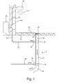
- Fig. 1 is a schematic view of a heat exchanger 2 according to the invention connected to a shower drain.
- hot water 34 is needed.
- the hot water 34 is supplied by a hot water supply 48.
- the hot water supply 48 is connected to the shower mixer (not shown) and the shower head 36 via a pipe 38 extending through a wall 50.
- the pipe 38 is integrated in the wall 50 to connect the hot water supply 48 and the shower head 36. Upon turning on the shower, water 34 will flow through the pipes 38 from the hot water supply 48 and pour out from the shower head 36. The water 34 hereafter falls down onto the bathroom floor 44, from where the water 34 flows through the shower grate 46 into the sewage pipe 42.
- the bathroom floor 44 is inclined towards the shower grate 46, so that the water 34 will enter the sewage pipe 42.
- the sewage pipe 42 is connected to the first end 18 of the heat exchanger 2 by an end element 30.
- the second end 20 of the heat exchanger 2 is also connected to a sewage pipe 42' by means of an end element 30'.
- the heat exchanger 2 comprises a first conduit (not shown but can be seen in Fig. 2 ) and a plurality of conduits (not shown but can be seen in Fig. 2 ).
- Shower water 34 is passing through the first conduit 4 in the heat exchanger 2 into the sewage pipe 42'.
- An inlet 40 is attached to the end element 30'.
- the inlet 40 is connected to a pipe 38'.
- Cold drinking water 34 is flowing through the pipe.
- the drinking water 34 enters the inlet 40 and flows through a plurality of additional conduits (not shown in Fig. 1 - see Fig. 2 ) in the heat exchanger 2.
- the water 34 passes through the end element 30 and leaves through the outlet 52, and through the pipe 38" the water enters the hot water supply 48.
- the water 34 from the shower is forced to flow through the sewage pipes 42, 42' and the heat exchanger 2.
- the hot water 34 from the shower warms up the heat exchanger 2 and through heat transfer, the cold water 34 flowing from the inlet 40 and through the heat exchanger 2 out through the outlet 52 is heated.
- the flow direction of the cold water flowing through the pipe 38' into the heat exchanger 2 is the opposite of the flow direction of the hot water 34 from the shower flowing through the heat exchanger 2.
- the heat exchanger 2 is mounted in a house with two storeys.
- the first storey may be a basement.
- the shower is installed at the 2 nd storey and the sewage pipe 42, 42' and the heat exchanger 2 is installed at the 1 st storey.
- the heat exchanger 2 comprises inspection conduits (see Fig. 2 ) which function as a safety mechanism for detection if the heat exchanger 2 is subjected to corrosion. If the heat exchanger 2 is corroded, water from the plurality of additional conduits (see Fig. 2 ) or shower water from the first conduit (see Fig.2 ) will flow into the inspection conduits (not shown). This will result in water from either the first conduit (not shown) or the plurality of conduits (not shown) or both dripping onto the floor from the inspection conduits (not shown).
- Fig. 2 illustrates schematic perspective cross-sectional views of a heat exchanger 2 without the end element 30.
- Fig. 2 displays only the first end 18 of the heat exchanger 2.
- Fig. 2 a) and Fig. 2 b) shows the same heat exchanger 2, but with different inclined cuts.
- the heat exchanger 2 is made of a metal, which is preferably aluminium because of its good thermal conductivity.
- the heat exchanger 2 is made by extrusion of the metal, and it comprises three cylindrical (hollow) rods 26, 26', 26".
- the three cylindrical rods 26, 26', 26" are arranged in such a manner that they constitute a triple rod system having a centre longitudinal axis X.
- the three cylindrical rods 26, 26', 26" cannot move independently of each other as they are extruded to constitute one unit - a one-piece body.
- Each of the three rods 26, 26', 26" have a wall 8, 10, 12.
- the inner rod 26 has a first wall 8.
- the inner rod 26 may function as a pipe, which is used to carry the wastewater away from the sink or shower and into the sewage.
- the inner rod 26 is centrally arranged within the second rod 26'.
- the second rod 26' has a second wall 10.
- the inner rod 26 and the second rod 26' are attached to each other in such a manner that the first wall 8 is integrated and mechanically connected to the second wall 10.
- the second wall 10 comprises a plurality of inspection conduits 14 extending parallel to the longitudinal axis X.
- the inspection conduits 14 are uniformly distributed along the second wall 10. It is possible to detect corrosion of the metal rods by means of these inspection conduits 14.
- the inspection conduits 14 therefore function as a safety mechanism to prevent wastewater to be mixed with the drinking water.
- the inspection conduits 14 are not closed at the first end or at the second end of the heat exchanger 2, and they are not in contact with any of the fluids flowing through the heat exchanger. Accordingly, fluid (e.g. water) will only drip onto the floor from the inspection conduits 14, if the metal is corroded.
- the second rod 26' is centrally arranged within the third rod 26".
- the third rod 26" has an outer wall 12 and an outer surface 16.
- the outer wall 12 comprises a plurality of additional conduits 6.
- the plurality of additional conduits 6 are equal in size and shape, and are uniformly distributed along the outer wall 12.
- the plurality of additional conduits 6 are used to transport a fluid (e.g. water) to be heated by means of the heat exchanger 2.
- the hot water will enter the drain and flow into the heat exchanger 2. Because the heat exchanger 2 is made of a metal, thermal energy from the wastewater or drainage water will be transferred to the metal and further to the walls 8, 10, 12, which will transfer thermal energy to the cold water flowing in the plurality of additional conduits 6.
- the cold water flowing through the additional conduits 6 will be heated by heat exchange, where thermal energy is transferred from the wastewater to the water flowing through the additional conduits 6.
- the heat exchanger 2 according to the present invention is very efficient, because the plurality of additional conduits 6 have a large surface area compared to their volume. Thus, the area-volume ratio is large and therefore, the heat exchanger 2 has a high ability to transfer thermal energy.
- the heat exchanger 2 comprises one or more extruded one-piece body.
- the extruded one-piece body is composed of aluminum, which has a high thermal conductivity, but the extruded one-piece body may also be constructed in another metal or metal alloy having a high thermal conductivity.
- the extruded one-piece body comprises a triple rod system, which comprises three hollow cylindrical rods.
- the inner rod comprises a first conduit 4, whereas the outer rod comprises a plurality of additional conduits 6, 6'.
- the first conduit 4 defines a first fluid passageway canal.
- the first conduit may be configured to transport wastewater or another fluid e.g. drinking water.
- the first conduit 4 is enclosed by a first wall 8, whereas the heat exchanger 2 is enclosed by an outer wall 12.
- the plurality of additional conduits 6, 6' define a number of fluid passageway canals, which may be configured to transport water.
- the second rod is cylindrical and comprises a plurality of inspection conduits 14.
- the inspection conduits 14 are intended to be used to inspect if the extruded one-piece body is corroded. If the one-piece body is corroded, water from the plurality of additional conduits 6, 6' or the first conduit 4 will flow or drip through the inspection conduits 14. It is therefore easy by visual inspection to determine if the heat exchanger is corroded.
- the fluid flowing in the first conduit 4 has a first temperature prior to entering the heat exchanger 2.
- the heat exchanger 2 is heated (or cooled). Heating (or cooling) the heat exchanger 2 will change the temperature of the fluid through heat exchange.
- Exchanged heat 28 from the extruded one-piece body to the plurality of conduits 6, 6' may heat or cool the fluid (e.g. water) flowing in the plurality of additional conduits 6, 6'.
- fluid e.g. water
- the plurality of conduits 6, 6' have an oval cross-section as shown in Fig. 3 a) , however the plurality of additional conduits 6,6' may have any other suitable shape. Examples of other types of shapes of the plurality of additional conduits 6, 6' are shown in Fig. 3 c), e) and f) .
- the cross-sectional shape may for example be rectangular as shown in Fig. 3 f) , or oblong as shown in Fig. 3 e) , or has an irregular shape as shown in Fig. 3 c) .
- the plurality of additional conduits 6, 6' may advantageously have incorporated turbulence generating members 22, 24.
- the turbulence generating members 22, 24 prevent the fluid in the plurality of additional conduits 6, 6' to have a laminar flow. This achieves a more efficient heat exchange 28 between the fluid and the material (e.g. aluminium) of the one-piece extruded body.
- the turbulence generating members 22, 24 are members which can generate turbulence in the canal in the plurality of conduits 6, 6'. Such members can be either separate members or members attached to the canal in the plurality of conduits 6, 6'. The attached members as shown in Fig. 3 b) cannot be moved inside the canal, whereas the separate members may be arranged in the canal as shown in Fig. 3 d) .
- the turbulence generating members 22 have several bends or structures enabling the members to prevent a laminar flow of the fluid.
- An example of an attached member is shown in Fig. 3 b) .
- the attached member 24 has the length of the canal in the plurality of conduits 6, 6' and has a small width, such that water can flow between each member.
- a portion of or all of the additional conduits 6, 6' may have one or more attached turbulence generating members 24.
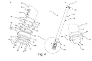
- a heat exchanger 2 with the end elements 30 and 30' is shown.
- the heat exchanger 2 comprises one segment 32, wherein the segment 32 comprises one extruded body piece S 1 .
- the extruded body piece S 1 is composed of a metal, preferably aluminium.
- the heat exchanger 2 has a first end 18 and a second end 20.
- an end element 30 or 30' is inserted.
- the first end 18 matches the second end 20, and the two end elements 30 and 30' are identical.
- the extruded one-piece body S 1 comprises a triple rod system wherein three cylindrical hollow rods 26, 26', 26" are arranged.
- the three cylindrical rods 26, 26', 26" cannot move independently of each other, since they are extruded into a one-piece body.
- Each of the three rods 26, 26', 26" have a wall 8, 10, 12.
- the cylindrical rod 26 is centrally arranged and has a first wall 8.
- the inner rod 26 constitutes a pipe, which is used to carry the fluid (e.g. wastewater away from the sink or shower and into the sewage).
- the inner rod 26 is centrally arranged within the second rod 26'.
- the second rod 26' has a second wall 10.
- the second wall 10 comprises a plurality of inspection conduits 14 extending along the length of the heat exchanger.
- the inspection conduits 14 are uniformly distributed along the periphery of the second wall 10. It is possible to detect corrosion of the heat exchanger by means of the inspection conduits 14.
- the second rod 26' is centrally arranged inside the third rod 26".
- the third rod 26" has an outer wall 12.
- the outer wall 12 comprises a plurality of additional conduits 6.
- the plurality of additional conduits 6 have the same size and shape and are uniformly distributed along the periphery of the outer wall 12.
- turbulence generating members 22 are provided in the plurality of additional conduits 6. These turbulence generating members 22 may not be part of the extruded one-piece body S 1 , but may be separate members movably arranged in the plurality of additional conduits 6.
- the turbulence generating members 22 comprise means for preventing a laminar flow of the water inside the plurality of conduits 6.
- the turbulence generating members 22 may comprise bends and other structures preventing fluid from having a laminar flow.
- a turbulent fluid flow increases the efficiency of the heat exchanger.
- a schematic exploded view of the end element 30' is also shown.
- the function of the end elements 30, 30' is to provide an easy way of connecting the heat exchanger 2 to external pipes (e.g. hot water supply, the main heating supply).
- the end elements 30, 30' prevent fluid leakage from the plurality of additional conduits 14.
- the end element 30 comprises several parts.
- a ring 58 is placed on the flange 76 of the wall 12 on the extruded one-piece body S 1 .
- the ring 58 comprises a profile 62.
- the profile is constructed in such a manner that an O-ring 60 can be placed in the profile 62, so that the O-ring 60 is arranged between the ring 58 and the interconnection member 72.
- the ring 58 also comprises holes 66 for which fastening means (screws) 64 can be inserted.
- the interconnection member 72 has a cylindrical shape. At both ends of the cylinder, a profile 62' is provided. An O-ring 60' can be placed at each end of the interconnection member 72.
- the interconnection member 72 comprises a threaded hole 70 into which a transition piece 68 is configured to be fitted.
- a ring 58' corresponding to the ring 58 is fitted on the interconnection member 72, so that an O-ring 60' is arranged between the interconnection member 72 and the ring 58'.
- the ring 58, interconnection member 72, and the ring 58' are attached to each other by bolts 64.
- Holes 66 are provided in the ring 58, the interconnection member 72 and the ring 58'. These holes 66 extend along the longitudinal axis of the elements 30'. The holes 66 are intended to receive a plurality of bolts 64 that are configured to receive corresponding nuts 56.
- the end element 30 is attached and fastened onto the first end 18 as shown in Fig. 3 a) .
- the ring 58 bears against the flange 76 of the outer wall 12.
- the ring 58' bears against the flange 74 of the second wall 10.
- the interconnection member 72 is arranged between the two rings 58 and 58'.
- the heat exchanger 2 comprises 5 a plurality of segments. Each segment is an extruded one-piece body S 1 , S 2 , S 3 , S 4 , S 5 .
- the extruded one-piece bodies S 1 , S 2 , S 3 , S 4 , S 5 are identical. This is advantageous, because the heat exchanger 2 can be extended or shortened depending on the installation circumstance.
- connection member 52 can be used to connect two of the extruded one-piece bodies S 1 , S 2 , S 3 , S 4 , S 5 .
- the connection member 52 comprises a sealing member (not shown) which prevents fluid leakage.
- the sealing member is an O-ring, but may be any type of sealing member.
- Each extruded one-piece body S 1 , S 2 , S 3 , S 4 , S 5 comprises a triple rod system as described with reference to Fig. 3 .
- wastewater may flow through the inner rod and the cold water may flow through the plurality of additional conduits in the outer rod.
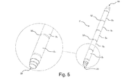
- Fig. 6 an alternative embodiment of the invention is shown. After extruding the extruded one-piece body, the body is rolled or milled, which results in a pattern in the third rod 26" (see Fig. 4 ) and the outer wall 12. The rolling process removes some of the metal material and thereby produces a pattern.
- the pattern may be symmetrical.
- profiles are generated on the third rod 26" and the outer wall 12. It may be advantageous to roll or mill the heat exchanger 2, because the profiles 78 generate turbulence in the additional conduits 6.
- Generating turbulence in the additional conduits 6 by rolling or milling the extruded one-piece body eliminates the need for inserting turbulence generating members into the additional conduits.
- the profiles 78 are configured to generate turbulence in the fluid flowing in the plurality of additional conduits 6 by the variation in the width of the conduits 6.
- Fig. 7 illustrates an embodiment of the heat exchanger 2 according to the invention.
- the heat exchanger 2 is installed in the floor 44 of the bathroom and is connected to the sewage pipes 42, 42' by the end elements 30, 30'.
- Water 34 is heated in the hot water supply 48 and transferred from the hot water supply 48 through the pipe 38 and into the showerhead 36.
- the showerhead 36 pours water 34 into the shower.
- the hot water supply 48 is connected to the showerhead 36 and shower mixer (not shown) through a wall 30 by the pipe 38.
- the pipe 38 extends through the wall 30. Water 34 pouring from the showerhead 36 falls onto the bathroom floor 44 and is forced to enter the sewage pipe 42 through a shower grate 46.
- the water from the shower flows into the first conduit (not shown) in the heat exchanger 2 and through the heat exchanger 2 and into the sewage pipe 42' through an end element 30.
- an outlet 52 is arranged, whereas an inlet 40 is provided at the end element 30'.
- Water 34 which is intended to be used in the shower enters the pipe 38' and flows through the inlet 40 and further through the plurality of additional conduits (not shown) of the heat exchanger 2.
- the water is warmed by the heat exchanger 2 and leaves the outlet 52 and enters the hot water supply 48 through the pipes 38".
- the energy used in the water supply 48 to warm the water is decreased, because the water is preheated from the heat exchanger 2.
- a rubber sleeve 80 with two clamps 82 is shown.
- the rubber sleeve 80 is used to fit the heat exchanger 2 onto the drainpipe or wastewater pipe.
- the two clamps 82 are used to fasten the rubber sleeve onto the wastewater pipe (not shown) and the heat exchanger (not shown).
- the rubber sleeve 80 with two clamps 82 prevents the wastewater pipe (not shown) and the heat exchanger (not shown) to disconnect, and prevents leakage of water from the connection.
Abstract
Description
- The present invention generally relates to a heat exchanger. The present invention more particularly relates also to a heat exchanger configured to exchange heat from hot wastewater from a drainage such as a shower drainage.
- Heat exchangers are often fitted to the bath/shower drainpipe and use heat from wastewater to preheat the mains supply to the shower or radiators. Because the heat from the wastewater can be reused to heat the house or water, house owners can save money on the heating bills.
- A heat exchanger made by an extrusion process is described in the patent application
EP 0906796 . The heat exchanger comprises a plate to which several tubes are attached. A liquid with a first temperature flows through the tubes, whereas a liquid with another temperature flows around the plate. The heat exchanger is preferably composed of aluminium, which makes the heat exchanger more efficient to transfer heat from the warmer liquid to the cooler liquid. However, the heat exchanger is inefficient and inapplicable in many applications due to the plate design. - The patent application
WO 2010/140138 discloses an extruded siphon piping and a moulded main component. The heat exchanger comprises a main pipe configured to transport hot wastewater. A coil with flowing cold water is arranged around the main pipe. The cold water will then be heated by the hot wastewater by heat exchange. The coil is preferably made of copper and is prepared by moulding. - Also in
WO 2011/011892 a heat exchanger has been designed to heat the main water supply by using the warm wastewater from a household shower or bath system. The heat exchanger comprises a unique helical or serpentine double walled conduit, which is arranged around an inner conduit. The inner conduit comprises the drainpipe, whereas the helical or serpentine double walled conduit comprises the cold water which is to be heated by the wastewater. - In several applications, it is essential to be able to discover corrosion of the heat exchanger since a mix of the fluids may cause contamination of the fluids. In domestic application using utility water, it is mandatory to be able to examine the heat exchanger for detection of general and local corrosion or erosion.
- Accordingly, there is a need for a heat exchanger that makes it possible to examine the heat exchanger for detection of general and local corrosion or erosion.
- It would also be desirable to have a heat exchanger having a design that is easy and cheap to manufacture, and which is highly efficient when transferring thermal energy between two liquids.
- The object of the present invention can be achieved by a heat exchanger having the features as defined in
claim 1. Preferred embodiments are defined in the dependent sub claims and explained in the following description and illustrated in the accompanying drawings. - The heat exchanger according to the invention is a heat exchanger having a longitudinal axis, a first end, a second end, an outer wall having an outer surface and a first conduit defining a first fluid passageway canal and a plurality of additional conduits defining a plurality of fluid passageway canals, wherein the first conduit and the additional conduits extend parallel to the longitudinal axis and that the heat exchanger comprises one or more extruded one-piece bodies comprising at least a portion of the first conduit and at least a portion of the additional conduits, wherein the heat exchanger comprises one or more inspection conduits provided between the first conduit and a plurality of conduits.
- Hereby it is possible to provide an efficient heat exchanger that is easy and cheap to manufacture and that makes it possible to examine the heat exchanger for detection of general and local corrosion or erosion.
- It is preferred that the inspection conduits contain no liquid during normal conditions. The inspection conduits will contain liquid in case of corrosion or erosion of the heat exchanger.
- It may be beneficial that an inner wall encloses the first conduit whereas a second wall encloses the inspection conduits and the first conduit.
- It is advantageous that two walls separate the first conduit and the plurality of additional conduits, because it limits the possibility of mixing the fluid in the conduit and in the plurality of additional conduits, respectively, e.g. due to corrosion of the extruded material (metal).
- It may be advantageous to have inspection conduits in between the first conduit and the plurality of conduits. These inspection conduits provide a method for determining if the extruded one-piece bodies are corroded. If the extruded one-piece bodies are not corroded, no fluid (e.g. water) will flow through the inspection conduits. However, if the extruded one-piece body is corroded fluid will drip from the first conduit or the plurality of conduits and into the inspection conduits.
- The heat exchanger comprises a first end and a second end. The two ends are configured to be connected to a pipe such as drainpipe or wastewater pipe.
- The heat exchanger comprises at least two sets of walls. The first wall encloses a first conduit. The first conduit constitutes a first fluid passageway canal.
- It may be advantageous that the first conduit is configured to be connected to a pipe guiding away wastewater or drain water, so that the first conduit leads the wastewater away from the drain.
- The heat exchanger is enclosed by an outer wall. A plurality of additional conduits are enclosed between the outer wall and the first conduit. These additional conduits constitute additional fluid passageway canals.
- Both the first conduit and the additional conduits extend parallel to the longitudinal axis of the heat exchanger. The additional conduits constitute canals configured to lead water to be heated into and out of the heat exchanger.
- Water (e.g., drinking water or water entering a radiator) may be heated by heat exchange by use of the heat exchanger. The wastewater or drain water has often a high temperature when entering the heat exchanger, whereas the water to be heated often has a lower temperature. The heat exchanger is designed in such a way that the water and wastewater cannot mix. Additionally, the water with the highest temperature can exchange heat/energy with the water with the lower temperature.
- Such an energy exchange causes a temperature increase of the water with the lowest temperature. If for example, the drinking water is used in the shower, the drinking water will be warmed by the wastewater and thereby limiting the amount of energy used, when heating the drinking water to the appropriate bathing temperature.
- The flow direction of the fluid (e.g. water) flowing through the first conduit and the flow direction of the fluid (e.g. water) flowing through the additional conduits may be either the same or opposite. However, the flow direction of the fluid (e.g. water) flowing through all additional conduits is the same.
- It may be advantageous, that the flow direction of the fluid flowing through the first conduit and the flow direction of the fluid flowing through the additional conduits is opposite.
- It may be advantageous, that the hot fluid (e.g. wastewater) enters and flows through the first conduit, and that the fluid to be heated (e.g. drinking water) enters and flows through the additional conduits. However, in some circumstances it may also be beneficial that the fluid to be heated (e.g. drinking water) enters and flows through the first conduit and that the hot fluid (e.g. wastewater) flows through the additional conduits.
- In general, it may be an advantage that the first conduit has a larger cross-section area, than each of the additional conduits.
- The heat exchanger comprises one or more one-piece bodies. Each of the one-piece bodies may be identical so that they can easily be connected two by two (where each one-piece body is in continuation of the other). This may be advantageous, because the heat exchanger then can be extended to fit into any type of installation.
- It may be an advantage that the one-piece body is a metal body made by an extrusion process. The one-piece body may be any metal or metal alloy having good thermal conductivity.
- It may beneficial that the one-piece body is made in aluminium. The one or more extruded one-piece bodies comprise the first conduit and the additional conduits. The first conduit comprises a first wall and an outer wall that encloses the heat exchanger. The outer wall comprises an outer surface constituting the periphery of the heat exchanger.
- It may be beneficial that the one-piece is an extruded body because it comprises only a single one-piece body. A significantly poorer thermal conductivity is achieved (between the two or more bodies) when the heat exchanger comprises two or more bodies. Thereby, no loss of thermal energy is generated in the one-piece body compared to a multiple body.
- It may be advantageous that the one-piece is an extruded body because a one-piece body is cheaper to manufacture than a body comprising multiple parts. The parts in a multiple part body needs to be joined into one body. Joining parts may be difficult and have negative side effects, as joint bodies are more vulnerable to corrosion. Furthermore, incorrect welding or metalwork at the joining members may result in leakage when the heat exchanger is used.
- In case of surface treatment of the heat exchanger, it is beneficial to extrude the one-piece body into one unit. Hereby it is avoided that the surface treatment is damaged while the one-piece body is subject to any further welding or metalworking.
- It may be an advantage that the first conduit is centrally arranged in the one or more extruded one-piece bodies and that the additional conduits are provided in a shorter distance to the outer surface than the first conduit.
- Hereby it is achieved that the heat can easily be exchanged between the fluid flowing through the first conduit (e.g. wastewater) and the material (preferably metal) of the extruded one-piece bodies and the fluid (e.g. utility water or water for industrial use) that needs to be heated. The thermal heat exchange is highly efficient due to the geometry of the extruded one-piece body, because the first conduit is centrally arranged and the plurality of additional conduits are surrounding the first conduit (e.g. in a symmetric pattern).
- It may be beneficial that the outer wall of the heat exchanger has a circular cross-section and that the first conduit has a circular cross-section.
- Hereby it is achieved that the heat exchanger is easy to manufacture by extrusion, because the heat exchanger comprises no corners.
- Since the first conduit has a circular cross-section, it has no corners. Corners in conduits are disadvantageous, because corners create water dead spots. In dead spots, filth and bacteria will often accumulate thereby generating biofilms. These biofilms will eventually block the conduit if the conduit is not repeatedly cleaned.
- The plurality of additional conduits may have any suitable shape. It is desirable to have a shape, which has a big surface area to volume ratio. Examples of such shapes may be oval, irregular, oblong, and rectangular with rounded corners.
- It may be advantageous that the additional conduits have an essentially oval cross-section, because the oval cross-section result in a large surface area, is easy to manufacture and leaves no dead spots.
- Hereby an efficient exchange of heat between the material (e.g. metal) surrounding the additional conduits and the fluid flowing through these conduits can be achieved.
- It may be an advantage that at least a portion of the plurality of additional conduits and/or the first conduit comprise turbulence generating members. It may be advantageous, that the plurality of additional conduits comprise turbulence generating members. It may be beneficial, that the first conduit comprises one or more turbulence generating members.
- Hereby it is achieved that efficiency of the heat exchanger can be increased, since a more effective mixing of different portions of the fluids is achieved.
- It may be beneficial that the additional conduits have turbulence generating members. The turbulence generating members will generate turbulence in the fluid, and the turbulence causes mixing of the fluid flowing through the additional conduits to a much larger extent than when the flow is laminar.
- The turbulence generating members may either be attached to the conduits, or be separate members movably arranged in the conduits.
- If the turbulence generating members are mechanically attached to the conduits, the turbulence generating members may be extruded as part of the extruded one-piece body. Hereby it is achieved that the turbulence generating members are easy and cheap to manufacture as part of the extruded one-piece body. However, filth and bacteria may accumulate around the attached turbulence generating members, which requires maintenance of the heat exchanger to prevent the conduits to block.
- Therefore, it may be advantageous that the turbulence generating members are separate members movably arranged in the conduits. During maintenance of the heat exchanger, it will be easy to remove the turbulence generating members and clean the heat exchanger to remove filth and bacteria/biofilms.
- It is beneficial, that the turbulence generating members are separate members movably arranged in the additional conduits.
- Turbulence may also be generated in the plurality of conduits by providing a profile in the outer wall and surface. A profile in the outer wall of the extruded one-piece body may be produced after extrusion of the one-piece body by milling or rolling.
- It is advantageous, that a profile is provided in the outer wall, because the profile causes the width of the canal in the plurality of additional conduits to shorten. When the outer wall of the extruded one-piece body does not comprise a profile, the width of the canal in the plurality of conduits has the same size throughout the canal. However, when the outer wall of the extruded one-piece body comprises a profile, the width of the canal at that location in which the profile is provided may be narrower than in other portions of the canal. Changing the width of the canal, so that the canals width varies throughout the canal, produces turbulence in the water flowing through the canal. Generating turbulence in the water increases efficiency of the heat exchanger through an increased mixing of the fluid.
- The heat exchanger comprises one or more segments. Each segment comprises one or more extruded one-piece body.
- Hereby it is achieved that it is possible to elongate the heat exchanger so that it fits into any installation.
- The heat exchanger may have the same shape in the first end and the second end. Hereby it is achieved that two or more segments may easily be joined to extend the heat exchanger. Two or more segments can easily be joined by a connection member, wherein the connection member comprises a sealing member preventing leakage.
- It may be beneficial that the heat exchanger has an end element attached to or provided at the first end and an end element attached to or provided at the second end.
- Hereby it is achieved that the heat exchanger can be connected to a pipe (e.g. a drain pipe or a wastewater pipe) through the end element. The end element may comprise either an inlet or an outlet. The fluid (e.g. water) flowing through the plurality of additional conduits may be entering the heat exchanger through the inlet in the end element and leaves the heat exchanger through the outlet at the other end element. The end elements may be configured to prevent fluid (e.g. water) from leaking when the fluid enters and leaves the heat exchanger.
- It may be advantageous that the heat exchanger comprises one or more inspection conduits provided between the first conduit and a plurality of conduits.
- Hereby it is achieved that two walls separate the fluid (e.g. water) within the first conduit and fluid (e.g. water) within the plurality of additional conduits.
- When using a heat exchanger vertically arranged, fluid will drip from the inspection conduits and onto the floor in case of leakage. Hereby it is possible by visual inspection to inspect if the heat exchanger is corroded and needs to be replaced.
- Heat is exchanged from the metal surrounding the plurality of additional conduits to the fluid flowing through the plurality of additional conduits. Hereby it is achieved that heat exchange is occurring from all sides of the plurality of additional conduits. This increases the efficiency of the heat exchanger.
- The invention will become more fully understood from the detailed description given herein below. The accompanying drawings are given by way of illustration only, and thus, they are not limitative of the present invention. In the accompanying drawings:
- Fig. 1
- shows a schematic view of a heat exchanger according to the invention inserted in a shower drain;
- Fig. 2
- shows a perspective cross-sectional view of a heat exchanger according to the invention;
- Fig. 3
- shows a schematic view of a heat exchanger according to the invention comprising an end element;
- Fig. 4
- shows a schematic view of a heat exchanger according to the invention comprising multiple segments;
- Fig. 5
- shows a schematic view of a heat exchanger according to the invention comprising a profile;
- Fig. 6
- shows a schematic view of a heat exchanger inserted in a shower drain and
- Fig. 7
- shows a rubber sleeve with two clamps.
- Referring now in detail to the drawings for the purpose of illustrating preferred embodiments of the present invention, a
heat exchanger 2 of the present invention is illustrated inFig. 2 . -
Fig. 1 is a schematic view of aheat exchanger 2 according to the invention connected to a shower drain. For comfortable shower taking,hot water 34 is needed. Thehot water 34 is supplied by ahot water supply 48. Thehot water supply 48 is connected to the shower mixer (not shown) and theshower head 36 via apipe 38 extending through awall 50. - The
pipe 38 is integrated in thewall 50 to connect thehot water supply 48 and theshower head 36. Upon turning on the shower,water 34 will flow through thepipes 38 from thehot water supply 48 and pour out from theshower head 36. Thewater 34 hereafter falls down onto thebathroom floor 44, from where thewater 34 flows through theshower grate 46 into thesewage pipe 42. - The
bathroom floor 44 is inclined towards theshower grate 46, so that thewater 34 will enter thesewage pipe 42. Thesewage pipe 42 is connected to thefirst end 18 of theheat exchanger 2 by anend element 30. Thesecond end 20 of theheat exchanger 2 is also connected to a sewage pipe 42' by means of an end element 30'. - The
heat exchanger 2 comprises a first conduit (not shown but can be seen inFig. 2 ) and a plurality of conduits (not shown but can be seen inFig. 2 ).Shower water 34 is passing through thefirst conduit 4 in theheat exchanger 2 into the sewage pipe 42'. Aninlet 40 is attached to the end element 30'. Theinlet 40 is connected to a pipe 38'.Cold drinking water 34 is flowing through the pipe. Thedrinking water 34 enters theinlet 40 and flows through a plurality of additional conduits (not shown inFig. 1 - seeFig. 2 ) in theheat exchanger 2. Hereafter thewater 34 passes through theend element 30 and leaves through theoutlet 52, and through thepipe 38" the water enters thehot water supply 48. - The
water 34 from the shower is forced to flow through thesewage pipes 42, 42' and theheat exchanger 2. Thehot water 34 from the shower warms up theheat exchanger 2 and through heat transfer, thecold water 34 flowing from theinlet 40 and through theheat exchanger 2 out through theoutlet 52 is heated. - The flow direction of the cold water flowing through the pipe 38' into the
heat exchanger 2 is the opposite of the flow direction of thehot water 34 from the shower flowing through theheat exchanger 2. Hereby it is possible to transfer a higher amount of thermal energy from the hot water to the cold water due to the higher temperature gradient between the two water temperatures. On the other hand, it would be possible to make aheat exchange 2 in which the flow directions of the cold water and hot water are identical. - The
heat exchanger 2 is mounted in a house with two storeys. The first storey may be a basement. The shower is installed at the 2nd storey and thesewage pipe 42, 42' and theheat exchanger 2 is installed at the 1st storey. - The
heat exchanger 2 comprises inspection conduits (seeFig. 2 ) which function as a safety mechanism for detection if theheat exchanger 2 is subjected to corrosion. If theheat exchanger 2 is corroded, water from the plurality of additional conduits (seeFig. 2 ) or shower water from the first conduit (seeFig.2 ) will flow into the inspection conduits (not shown). This will result in water from either the first conduit (not shown) or the plurality of conduits (not shown) or both dripping onto the floor from the inspection conduits (not shown). -
Fig. 2 illustrates schematic perspective cross-sectional views of aheat exchanger 2 without theend element 30.Fig. 2 displays only thefirst end 18 of theheat exchanger 2.Fig. 2 a) and Fig. 2 b) shows thesame heat exchanger 2, but with different inclined cuts. - The
heat exchanger 2 is made of a metal, which is preferably aluminium because of its good thermal conductivity. Theheat exchanger 2 is made by extrusion of the metal, and it comprises three cylindrical (hollow)rods cylindrical rods - The three
cylindrical rods rods wall - The
inner rod 26 has afirst wall 8. Theinner rod 26 may function as a pipe, which is used to carry the wastewater away from the sink or shower and into the sewage. Theinner rod 26 is centrally arranged within the second rod 26'. - The second rod 26' has a
second wall 10. Theinner rod 26 and the second rod 26' are attached to each other in such a manner that thefirst wall 8 is integrated and mechanically connected to thesecond wall 10. Thesecond wall 10 comprises a plurality ofinspection conduits 14 extending parallel to the longitudinal axis X. - The
inspection conduits 14 are uniformly distributed along thesecond wall 10. It is possible to detect corrosion of the metal rods by means of theseinspection conduits 14. Theinspection conduits 14 therefore function as a safety mechanism to prevent wastewater to be mixed with the drinking water. - If the
metal rods inspection conduits 14 are not closed at the first end or at the second end of theheat exchanger 2, and they are not in contact with any of the fluids flowing through the heat exchanger. Accordingly, fluid (e.g. water) will only drip onto the floor from theinspection conduits 14, if the metal is corroded. - The second rod 26' is centrally arranged within the
third rod 26". Thethird rod 26" has anouter wall 12 and anouter surface 16. Theouter wall 12 comprises a plurality ofadditional conduits 6. The plurality ofadditional conduits 6 are equal in size and shape, and are uniformly distributed along theouter wall 12. The plurality ofadditional conduits 6 are used to transport a fluid (e.g. water) to be heated by means of theheat exchanger 2. - When the heat exchanger is used for reusing thermal energy from a shower, the hot water will enter the drain and flow into the
heat exchanger 2. Because theheat exchanger 2 is made of a metal, thermal energy from the wastewater or drainage water will be transferred to the metal and further to thewalls additional conduits 6. - The cold water flowing through the
additional conduits 6 will be heated by heat exchange, where thermal energy is transferred from the wastewater to the water flowing through theadditional conduits 6. Theheat exchanger 2 according to the present invention is very efficient, because the plurality ofadditional conduits 6 have a large surface area compared to their volume. Thus, the area-volume ratio is large and therefore, theheat exchanger 2 has a high ability to transfer thermal energy. - In
Fig. 3 a) , a cross-sectional view of theheat exchanger 2 is shown. Theheat exchanger 2 comprises one or more extruded one-piece body. The extruded one-piece body is composed of aluminum, which has a high thermal conductivity, but the extruded one-piece body may also be constructed in another metal or metal alloy having a high thermal conductivity. The extruded one-piece body comprises a triple rod system, which comprises three hollow cylindrical rods. The inner rod comprises afirst conduit 4, whereas the outer rod comprises a plurality ofadditional conduits 6, 6'. Thefirst conduit 4 defines a first fluid passageway canal. - The first conduit may be configured to transport wastewater or another fluid e.g. drinking water. The
first conduit 4 is enclosed by afirst wall 8, whereas theheat exchanger 2 is enclosed by anouter wall 12. - The plurality of
additional conduits 6, 6' define a number of fluid passageway canals, which may be configured to transport water. - Between the outer cylindrical rod and the inner rod, a second rod is centrally arranged. The second rod is cylindrical and comprises a plurality of
inspection conduits 14. Theinspection conduits 14 are intended to be used to inspect if the extruded one-piece body is corroded. If the one-piece body is corroded, water from the plurality ofadditional conduits 6, 6' or thefirst conduit 4 will flow or drip through theinspection conduits 14. It is therefore easy by visual inspection to determine if the heat exchanger is corroded. - The fluid flowing in the
first conduit 4 has a first temperature prior to entering theheat exchanger 2. When the wastewater flows through theheat exchanger 2, theheat exchanger 2 is heated (or cooled). Heating (or cooling) theheat exchanger 2 will change the temperature of the fluid through heat exchange. - Exchanged
heat 28 from the extruded one-piece body to the plurality ofconduits 6, 6' may heat or cool the fluid (e.g. water) flowing in the plurality ofadditional conduits 6, 6'. - The plurality of
conduits 6, 6' have an oval cross-section as shown inFig. 3 a) , however the plurality ofadditional conduits 6,6' may have any other suitable shape. Examples of other types of shapes of the plurality ofadditional conduits 6, 6' are shown inFig. 3 c), e) and f) . The cross-sectional shape may for example be rectangular as shown inFig. 3 f) , or oblong as shown inFig. 3 e) , or has an irregular shape as shown inFig. 3 c) . - The plurality of
additional conduits 6, 6' may advantageously have incorporatedturbulence generating members turbulence generating members additional conduits 6, 6' to have a laminar flow. This achieves a moreefficient heat exchange 28 between the fluid and the material (e.g. aluminium) of the one-piece extruded body. - The
turbulence generating members conduits 6, 6'. Such members can be either separate members or members attached to the canal in the plurality ofconduits 6, 6'. The attached members as shown inFig. 3 b) cannot be moved inside the canal, whereas the separate members may be arranged in the canal as shown inFig. 3 d) . - The
turbulence generating members 22 have several bends or structures enabling the members to prevent a laminar flow of the fluid. An example of an attached member is shown inFig. 3 b) . Here the attachedmember 24 has the length of the canal in the plurality ofconduits 6, 6' and has a small width, such that water can flow between each member. A portion of or all of theadditional conduits 6, 6' may have one or more attachedturbulence generating members 24. - In
Fig. 4 ), aheat exchanger 2 with theend elements 30 and 30' is shown. Theheat exchanger 2 comprises onesegment 32, wherein thesegment 32 comprises one extruded body piece S1. The extruded body piece S1 is composed of a metal, preferably aluminium. Theheat exchanger 2 has afirst end 18 and asecond end 20. - At the
first end 18 and at thesecond end 20, anend element 30 or 30' is inserted. Thefirst end 18 matches thesecond end 20, and the twoend elements 30 and 30' are identical. - The extruded one-piece body S1 comprises a triple rod system wherein three cylindrical
hollow rods cylindrical rods - Each of the three
rods wall cylindrical rod 26 is centrally arranged and has afirst wall 8. Theinner rod 26 constitutes a pipe, which is used to carry the fluid (e.g. wastewater away from the sink or shower and into the sewage). - The
inner rod 26 is centrally arranged within the second rod 26'. The second rod 26' has asecond wall 10. Thesecond wall 10 comprises a plurality ofinspection conduits 14 extending along the length of the heat exchanger. Theinspection conduits 14 are uniformly distributed along the periphery of thesecond wall 10. It is possible to detect corrosion of the heat exchanger by means of theinspection conduits 14. - The second rod 26' is centrally arranged inside the
third rod 26". Thethird rod 26" has anouter wall 12. Theouter wall 12 comprises a plurality ofadditional conduits 6. The plurality ofadditional conduits 6 have the same size and shape and are uniformly distributed along the periphery of theouter wall 12. - In the plurality of
additional conduits 6,turbulence generating members 22 are provided. Theseturbulence generating members 22 may not be part of the extruded one-piece body S1, but may be separate members movably arranged in the plurality ofadditional conduits 6. - The
turbulence generating members 22 comprise means for preventing a laminar flow of the water inside the plurality ofconduits 6. Theturbulence generating members 22 may comprise bends and other structures preventing fluid from having a laminar flow. - A turbulent fluid flow increases the efficiency of the heat exchanger.
- A schematic exploded view of the end element 30' is also shown. The function of the
end elements 30, 30' is to provide an easy way of connecting theheat exchanger 2 to external pipes (e.g. hot water supply, the main heating supply). Theend elements 30, 30' prevent fluid leakage from the plurality ofadditional conduits 14. - The
end element 30 comprises several parts. Aring 58 is placed on theflange 76 of thewall 12 on the extruded one-piece body S1. Thering 58 comprises a profile 62. The profile is constructed in such a manner that an O-ring 60 can be placed in the profile 62, so that the O-ring 60 is arranged between thering 58 and theinterconnection member 72. - The
ring 58 also comprisesholes 66 for which fastening means (screws) 64 can be inserted. Theinterconnection member 72 has a cylindrical shape. At both ends of the cylinder, a profile 62' is provided. An O-ring 60' can be placed at each end of theinterconnection member 72. - The
interconnection member 72 comprises a threadedhole 70 into which atransition piece 68 is configured to be fitted. A ring 58' corresponding to thering 58 is fitted on theinterconnection member 72, so that an O-ring 60' is arranged between theinterconnection member 72 and the ring 58'. - The
ring 58,interconnection member 72, and the ring 58' are attached to each other bybolts 64.Holes 66 are provided in thering 58, theinterconnection member 72 and the ring 58'. Theseholes 66 extend along the longitudinal axis of the elements 30'. Theholes 66 are intended to receive a plurality ofbolts 64 that are configured to receive corresponding nuts 56. - The
end element 30 is attached and fastened onto thefirst end 18 as shown inFig. 3 a) . When inserting theend element 30 to thefirst end 18 orsecond end 20, thering 58 bears against theflange 76 of theouter wall 12. The ring 58' bears against theflange 74 of thesecond wall 10. Theinterconnection member 72 is arranged between the tworings 58 and 58'. - In
Fig. 5 , theheat exchanger 2 comprises 5 a plurality of segments. Each segment is an extruded one-piece body S1, S2, S3, S4, S5. The extruded one-piece bodies S1, S2, S3, S4, S5 are identical. This is advantageous, because theheat exchanger 2 can be extended or shortened depending on the installation circumstance. - To connect two of the extruded one-piece bodies S1, S2, S3, S4, S5, a
connection member 52 can be used. Theconnection member 52 comprises a sealing member (not shown) which prevents fluid leakage. - The sealing member is an O-ring, but may be any type of sealing member. Each extruded one-piece body S1, S2, S3, S4, S5 comprises a triple rod system as described with reference to
Fig. 3 . When the heat exchanger is applied to reuse hot water from a shower, wastewater may flow through the inner rod and the cold water may flow through the plurality of additional conduits in the outer rod. - In
Fig. 6 , an alternative embodiment of the invention is shown. After extruding the extruded one-piece body, the body is rolled or milled, which results in a pattern in thethird rod 26" (seeFig. 4 ) and theouter wall 12. The rolling process removes some of the metal material and thereby produces a pattern. The pattern may be symmetrical. - By removing material from the triple rod system, profiles are generated on the
third rod 26" and theouter wall 12. It may be advantageous to roll or mill theheat exchanger 2, because theprofiles 78 generate turbulence in theadditional conduits 6. - Generating turbulence in the
additional conduits 6 by rolling or milling the extruded one-piece body eliminates the need for inserting turbulence generating members into the additional conduits. - The
profiles 78 are configured to generate turbulence in the fluid flowing in the plurality ofadditional conduits 6 by the variation in the width of theconduits 6. -
Fig. 7 illustrates an embodiment of theheat exchanger 2 according to the invention. In this embodiment, theheat exchanger 2 is installed in thefloor 44 of the bathroom and is connected to thesewage pipes 42, 42' by theend elements 30, 30'. -
Water 34 is heated in thehot water supply 48 and transferred from thehot water supply 48 through thepipe 38 and into theshowerhead 36. - The
showerhead 36 pourswater 34 into the shower. Thehot water supply 48 is connected to theshowerhead 36 and shower mixer (not shown) through awall 30 by thepipe 38. - The
pipe 38 extends through thewall 30.Water 34 pouring from theshowerhead 36 falls onto thebathroom floor 44 and is forced to enter thesewage pipe 42 through ashower grate 46. - The water from the shower flows into the first conduit (not shown) in the
heat exchanger 2 and through theheat exchanger 2 and into the sewage pipe 42' through anend element 30. At theend element 30 anoutlet 52 is arranged, whereas aninlet 40 is provided at the end element 30'. -
Water 34 which is intended to be used in the shower enters the pipe 38' and flows through theinlet 40 and further through the plurality of additional conduits (not shown) of theheat exchanger 2. Hereafter the water is warmed by theheat exchanger 2 and leaves theoutlet 52 and enters thehot water supply 48 through thepipes 38". The energy used in thewater supply 48 to warm the water is decreased, because the water is preheated from theheat exchanger 2. - In
Fig. 8 , arubber sleeve 80 with twoclamps 82 is shown. Therubber sleeve 80 is used to fit theheat exchanger 2 onto the drainpipe or wastewater pipe. The two clamps 82 are used to fasten the rubber sleeve onto the wastewater pipe (not shown) and the heat exchanger (not shown). Therubber sleeve 80 with twoclamps 82 prevents the wastewater pipe (not shown) and the heat exchanger (not shown) to disconnect, and prevents leakage of water from the connection. -
- 2
- Heat exchanger
- 4
- First conduit
- 6, 6'
- Additional conduit
- 8
- First wall
- 10
- Second wall
- 12
- Outer wall
- 14
- Inspection conduits
- 16
- Outer surface
- 18
- First end
- 20
- Second end
- 22
- Turbulence generating member
- 24
- Turbulence generating member
- 26
- Inner cylindrical rod
- 26'
- Second cylindrical rod
- 26"
- Third cylindrical rod
- 28
- Heat exchange
- 30, 30'
- End element
- 32
- Segment
- 34
- Water
- 36
- Shower head
- 38, 38', 38"
- Pipe
- 40
- Inlet
- 42, 42'
- Sewage pipe
- 44
- Floor
- 46
- Shower grate
- 48
- Hot water supply
- 50
- Wall
- 52
- Outlet
- 54
- Connection member
- 56
- Nut
- 58
- Ring
- 60
- O-ring
- 62
- Profile
- 64
- Fastening means
- 66
- Holes for fastening means
- 68
- Transition piece
- 70
- Opening to transition piece
- 72
- Interconnection member
- 74
- Flange of second wall
- 76
- Flange of outer wall
- 78
- Profile
- 80
- Rubber sleeve
- 82
- Clamp
- S1, S2, S3, S4, S5
- One-piece body
Claims (11)
- A heat exchanger (2) having a longitudinal axis (x), a first end (18), a second end (20), an outer wall (12) having an outer surface (16) and a first conduit (4) defining a first fluid passageway canal and a plurality of additional conduits (6, 6') defining a plurality of additional fluid passageway canals, wherein the first conduit (4) and the additional conduits (6, 6') extend along the longitudinal axis (x) and that the heat exchanger (2) comprises one or more extruded one-piece bodies (S1, S2, S3) comprising at least a portion of the first conduit (4) and at least a portion of each of the additional conduits (6, 6'), characterised in that the heat exchanger (2) comprises one or more inspection conduits (14) provided between the first conduit (4) and a plurality of conduits (6, 6').
- A heat exchanger (2) according to claim 1, characterised in that the first conduit (4) is centrally arranged in the one or more extruded one-piece bodies (S1, S2, S3) and that the additional conduits (6, 6') are provided in a shorter distance to the outer surface (16) than the first conduit (4).
- A heat exchanger (2) according to claim 1 or claim 2, characterised in that the outer wall (12) of the heat exchanger (2) has a circular cross-section and that the first conduit (4) has a circular cross-section.
- A heat exchanger (2) according to one of the preceding claims, characterised in that the additional conduits (6, 6') have an essentially oval cross-section.
- A heat exchanger (2) according to one of the preceding claims, characterised in that at least a portion of the additional conduits (6, 6') comprise turbulence generating members (22, 24).
- A heat exchanger (2) according to claim 5, characterised in that the turbulence generating members (22, 24) are separate members movably arranged within at least a portion of the additional conduits (6, 6').
- A heat exchanger (2) according to one of the preceding claims, characterised in that one or more profiles (78) are provided in the outer wall (12).
- A heat exchanger (2) according to one of the preceding claims, characterised in that the heat exchanger (2) has the same shape in the first end (18) and in the second end (20).
- A heat exchanger (2) according to one of the preceding claims, characterised in that the heat exchanger (2) comprises several segments (32, S1, S2, S3).
- A heat exchanger (2) according to one of the preceding claims, characterised in that an end element (30) is attached to the first end (18) and an end element (30) is attached to the second end (20).
- A heat exchanger (2) according to one of the preceding claims, characterised in that the heat exchanger (2) comprises means for providing heat exchange (28) between material surrounding the additional conduits (6, 6') to a fluid flowing through the additional conduits (6, 6'), where the heat exchange (28) is provided along the entire periphery of the additional conduits (6, 6').
Applications Claiming Priority (1)
| Application Number | Priority Date | Filing Date | Title |
|---|---|---|---|
| DKPA201400288 | 2014-05-27 |
Publications (2)
| Publication Number | Publication Date |
|---|---|
| EP2963373A1 true EP2963373A1 (en) | 2016-01-06 |
| EP2963373B1 EP2963373B1 (en) | 2021-08-11 |
Family
ID=53365769
Family Applications (1)
| Application Number | Title | Priority Date | Filing Date |
|---|---|---|---|
| EP15169364.5A Active EP2963373B1 (en) | 2014-05-27 | 2015-05-27 | Heat exchanger |
Country Status (1)
| Country | Link |
|---|---|
| EP (1) | EP2963373B1 (en) |
Cited By (1)
| Publication number | Priority date | Publication date | Assignee | Title |
|---|---|---|---|---|
| US11835301B2 (en) | 2021-04-07 | 2023-12-05 | Ecoinnovation Technologies Incorporée | Modular heat exchanger and method of assembly thereof |
Citations (4)
| Publication number | Priority date | Publication date | Assignee | Title |
|---|---|---|---|---|
| GB2078927A (en) * | 1980-06-20 | 1982-01-13 | Grumman Energy Systems Inc | Heat exchange system |
| JPS59167697A (en) * | 1983-03-14 | 1984-09-21 | Matsushita Electric Ind Co Ltd | Triple-piped type heat exchanger equipped with breakage detector for pipe wall |
| US5254365A (en) * | 1987-08-10 | 1993-10-19 | Lanxide Technology Company, Lp | Method of making ceramic composite articles |
| DE102010024276A1 (en) * | 2010-06-18 | 2012-01-12 | Andreas Kaiser | Heat exchanger e.g. counter-flow heat exchanger, for transferring thermal energy from material flow to another material flow, has profiled tube formed as tube part and pipe-in-pipe system that comprises outer and inner pipe sections |
-
2015
- 2015-05-27 EP EP15169364.5A patent/EP2963373B1/en active Active
Patent Citations (4)
| Publication number | Priority date | Publication date | Assignee | Title |
|---|---|---|---|---|
| GB2078927A (en) * | 1980-06-20 | 1982-01-13 | Grumman Energy Systems Inc | Heat exchange system |
| JPS59167697A (en) * | 1983-03-14 | 1984-09-21 | Matsushita Electric Ind Co Ltd | Triple-piped type heat exchanger equipped with breakage detector for pipe wall |
| US5254365A (en) * | 1987-08-10 | 1993-10-19 | Lanxide Technology Company, Lp | Method of making ceramic composite articles |
| DE102010024276A1 (en) * | 2010-06-18 | 2012-01-12 | Andreas Kaiser | Heat exchanger e.g. counter-flow heat exchanger, for transferring thermal energy from material flow to another material flow, has profiled tube formed as tube part and pipe-in-pipe system that comprises outer and inner pipe sections |
Cited By (1)
| Publication number | Priority date | Publication date | Assignee | Title |
|---|---|---|---|---|
| US11835301B2 (en) | 2021-04-07 | 2023-12-05 | Ecoinnovation Technologies Incorporée | Modular heat exchanger and method of assembly thereof |
Also Published As
| Publication number | Publication date |
|---|---|
| EP2963373B1 (en) | 2021-08-11 |
Similar Documents
| Publication | Publication Date | Title |
|---|---|---|
| CN110260690B (en) | Heat exchanger and kit, fluid distribution manifold, turbulator and energy recovery system | |
| US9010407B2 (en) | Waste water heat recovery system | |
| US20110024080A1 (en) | Heat Exchanger | |
| DE102008017380A1 (en) | Heat exchanger in the form of double-walled tube for recovering waste heat from sewage useful in sewers, bathroom, kitchen and/or swimming pool, comprises an internal tube, which is made of thermal conductive material, and an external tube | |
| EP3245468B1 (en) | Heat exchanger | |
| CA3037942A1 (en) | Heat exchanging device | |
| EP2963373B1 (en) | Heat exchanger | |
| EP2693146B1 (en) | Heat exchanger for sewer riser | |
| CN106489008B (en) | Flushing assembly | |
| CN109186287A (en) | A kind of sanitation-grade ectonexine displaced type heat exchanger | |
| EP2689206B1 (en) | Heat exchanger | |
| US11193721B2 (en) | Heat recovery unit for gray water | |
| US20180355590A1 (en) | Device for Connecting at Least One Tap and a Pipe with Thermal Decoupling | |
| US20200109862A1 (en) | Fluid heat exchanger | |
| US20170254595A1 (en) | Waste water heat recovery system | |
| DK176316B1 (en) | Process for producing a water heater as well as a water heater | |
| RU2667244C1 (en) | Tubular spiral and heat exchanger with implementation thereof | |
| AU2004212549A1 (en) | Improved (shower drain) heat exchanger | |
| RU165848U1 (en) | HEAT EXCHANGER "PIPE IN PIPE" | |
| RU185391U1 (en) | SHELL-TUBE HEAT EXCHANGE UNIT | |
| WO2023104270A1 (en) | Heat exchanger water trap | |
| FI65487C (en) | ANORDNING FOER TILLVARATAGNING AV VAERME AV AVFALLSVATTEN | |
| RU158070U1 (en) | SPEED HEAT EXCHANGE UNIT | |
| RU2006755C1 (en) | Heating appliance | |
| RU2558485C1 (en) | Heat exchanger |
Legal Events
| Date | Code | Title | Description |
|---|---|---|---|
| PUAI | Public reference made under article 153(3) epc to a published international application that has entered the european phase |
Free format text: ORIGINAL CODE: 0009012 |
|
| AK | Designated contracting states |
Kind code of ref document: A1 Designated state(s): AL AT BE BG CH CY CZ DE DK EE ES FI FR GB GR HR HU IE IS IT LI LT LU LV MC MK MT NL NO PL PT RO RS SE SI SK SM TR |
|
| AX | Request for extension of the european patent |
Extension state: BA ME |
|
| STAA | Information on the status of an ep patent application or granted ep patent |
Free format text: STATUS: REQUEST FOR EXAMINATION WAS MADE |
|
| 17P | Request for examination filed |
Effective date: 20160705 |
|
| RBV | Designated contracting states (corrected) |
Designated state(s): AL AT BE BG CH CY CZ DE DK EE ES FI FR GB GR HR HU IE IS IT LI LT LU LV MC MK MT NL NO PL PT RO RS SE SI SK SM TR |
|
| GRAP | Despatch of communication of intention to grant a patent |
Free format text: ORIGINAL CODE: EPIDOSNIGR1 |
|
| STAA | Information on the status of an ep patent application or granted ep patent |
Free format text: STATUS: GRANT OF PATENT IS INTENDED |
|
| RIC1 | Information provided on ipc code assigned before grant |
Ipc: F28F 1/00 20060101ALI20210326BHEP Ipc: F28D 7/10 20060101AFI20210326BHEP |
|
| INTG | Intention to grant announced |
Effective date: 20210416 |
|
| GRAS | Grant fee paid |
Free format text: ORIGINAL CODE: EPIDOSNIGR3 |
|
| GRAA | (expected) grant |
Free format text: ORIGINAL CODE: 0009210 |
|
| STAA | Information on the status of an ep patent application or granted ep patent |
Free format text: STATUS: THE PATENT HAS BEEN GRANTED |
|
| AK | Designated contracting states |
Kind code of ref document: B1 Designated state(s): AL AT BE BG CH CY CZ DE DK EE ES FI FR GB GR HR HU IE IS IT LI LT LU LV MC MK MT NL NO PL PT RO RS SE SI SK SM TR |
|
| REG | Reference to a national code |
Ref country code: CH Ref legal event code: EP |
|
| REG | Reference to a national code |
Ref country code: DE Ref legal event code: R096 Ref document number: 602015072127 Country of ref document: DE |
|
| REG | Reference to a national code |
Ref country code: IE Ref legal event code: FG4D Ref country code: AT Ref legal event code: REF Ref document number: 1419794 Country of ref document: AT Kind code of ref document: T Effective date: 20210915 |
|
| REG | Reference to a national code |
Ref country code: LT Ref legal event code: MG9D |
|
| REG | Reference to a national code |
Ref country code: NL Ref legal event code: MP Effective date: 20210811 |
|
| REG | Reference to a national code |
Ref country code: AT Ref legal event code: MK05 Ref document number: 1419794 Country of ref document: AT Kind code of ref document: T Effective date: 20210811 |
|
| PG25 | Lapsed in a contracting state [announced via postgrant information from national office to epo] |
Ref country code: LT Free format text: LAPSE BECAUSE OF FAILURE TO SUBMIT A TRANSLATION OF THE DESCRIPTION OR TO PAY THE FEE WITHIN THE PRESCRIBED TIME-LIMIT Effective date: 20210811 Ref country code: BG Free format text: LAPSE BECAUSE OF FAILURE TO SUBMIT A TRANSLATION OF THE DESCRIPTION OR TO PAY THE FEE WITHIN THE PRESCRIBED TIME-LIMIT Effective date: 20211111 Ref country code: AT Free format text: LAPSE BECAUSE OF FAILURE TO SUBMIT A TRANSLATION OF THE DESCRIPTION OR TO PAY THE FEE WITHIN THE PRESCRIBED TIME-LIMIT Effective date: 20210811 Ref country code: FI Free format text: LAPSE BECAUSE OF FAILURE TO SUBMIT A TRANSLATION OF THE DESCRIPTION OR TO PAY THE FEE WITHIN THE PRESCRIBED TIME-LIMIT Effective date: 20210811 Ref country code: ES Free format text: LAPSE BECAUSE OF FAILURE TO SUBMIT A TRANSLATION OF THE DESCRIPTION OR TO PAY THE FEE WITHIN THE PRESCRIBED TIME-LIMIT Effective date: 20210811 Ref country code: PT Free format text: LAPSE BECAUSE OF FAILURE TO SUBMIT A TRANSLATION OF THE DESCRIPTION OR TO PAY THE FEE WITHIN THE PRESCRIBED TIME-LIMIT Effective date: 20211213 Ref country code: NO Free format text: LAPSE BECAUSE OF FAILURE TO SUBMIT A TRANSLATION OF THE DESCRIPTION OR TO PAY THE FEE WITHIN THE PRESCRIBED TIME-LIMIT Effective date: 20211111 Ref country code: HR Free format text: LAPSE BECAUSE OF FAILURE TO SUBMIT A TRANSLATION OF THE DESCRIPTION OR TO PAY THE FEE WITHIN THE PRESCRIBED TIME-LIMIT Effective date: 20210811 Ref country code: SE Free format text: LAPSE BECAUSE OF FAILURE TO SUBMIT A TRANSLATION OF THE DESCRIPTION OR TO PAY THE FEE WITHIN THE PRESCRIBED TIME-LIMIT Effective date: 20210811 Ref country code: RS Free format text: LAPSE BECAUSE OF FAILURE TO SUBMIT A TRANSLATION OF THE DESCRIPTION OR TO PAY THE FEE WITHIN THE PRESCRIBED TIME-LIMIT Effective date: 20210811 |
|
| PG25 | Lapsed in a contracting state [announced via postgrant information from national office to epo] |
Ref country code: PL Free format text: LAPSE BECAUSE OF FAILURE TO SUBMIT A TRANSLATION OF THE DESCRIPTION OR TO PAY THE FEE WITHIN THE PRESCRIBED TIME-LIMIT Effective date: 20210811 Ref country code: LV Free format text: LAPSE BECAUSE OF FAILURE TO SUBMIT A TRANSLATION OF THE DESCRIPTION OR TO PAY THE FEE WITHIN THE PRESCRIBED TIME-LIMIT Effective date: 20210811 Ref country code: GR Free format text: LAPSE BECAUSE OF FAILURE TO SUBMIT A TRANSLATION OF THE DESCRIPTION OR TO PAY THE FEE WITHIN THE PRESCRIBED TIME-LIMIT Effective date: 20211112 |
|
| PG25 | Lapsed in a contracting state [announced via postgrant information from national office to epo] |
Ref country code: NL Free format text: LAPSE BECAUSE OF FAILURE TO SUBMIT A TRANSLATION OF THE DESCRIPTION OR TO PAY THE FEE WITHIN THE PRESCRIBED TIME-LIMIT Effective date: 20210811 |
|
| PG25 | Lapsed in a contracting state [announced via postgrant information from national office to epo] |
Ref country code: DK Free format text: LAPSE BECAUSE OF FAILURE TO SUBMIT A TRANSLATION OF THE DESCRIPTION OR TO PAY THE FEE WITHIN THE PRESCRIBED TIME-LIMIT Effective date: 20210811 |
|
| REG | Reference to a national code |
Ref country code: DE Ref legal event code: R097 Ref document number: 602015072127 Country of ref document: DE |
|
| PG25 | Lapsed in a contracting state [announced via postgrant information from national office to epo] |
Ref country code: SM Free format text: LAPSE BECAUSE OF FAILURE TO SUBMIT A TRANSLATION OF THE DESCRIPTION OR TO PAY THE FEE WITHIN THE PRESCRIBED TIME-LIMIT Effective date: 20210811 Ref country code: SK Free format text: LAPSE BECAUSE OF FAILURE TO SUBMIT A TRANSLATION OF THE DESCRIPTION OR TO PAY THE FEE WITHIN THE PRESCRIBED TIME-LIMIT Effective date: 20210811 Ref country code: RO Free format text: LAPSE BECAUSE OF FAILURE TO SUBMIT A TRANSLATION OF THE DESCRIPTION OR TO PAY THE FEE WITHIN THE PRESCRIBED TIME-LIMIT Effective date: 20210811 Ref country code: EE Free format text: LAPSE BECAUSE OF FAILURE TO SUBMIT A TRANSLATION OF THE DESCRIPTION OR TO PAY THE FEE WITHIN THE PRESCRIBED TIME-LIMIT Effective date: 20210811 Ref country code: CZ Free format text: LAPSE BECAUSE OF FAILURE TO SUBMIT A TRANSLATION OF THE DESCRIPTION OR TO PAY THE FEE WITHIN THE PRESCRIBED TIME-LIMIT Effective date: 20210811 Ref country code: AL Free format text: LAPSE BECAUSE OF FAILURE TO SUBMIT A TRANSLATION OF THE DESCRIPTION OR TO PAY THE FEE WITHIN THE PRESCRIBED TIME-LIMIT Effective date: 20210811 |
|
| PLBE | No opposition filed within time limit |
Free format text: ORIGINAL CODE: 0009261 |
|
| STAA | Information on the status of an ep patent application or granted ep patent |
Free format text: STATUS: NO OPPOSITION FILED WITHIN TIME LIMIT |
|
| 26N | No opposition filed |
Effective date: 20220512 |
|
| PG25 | Lapsed in a contracting state [announced via postgrant information from national office to epo] |
Ref country code: IT Free format text: LAPSE BECAUSE OF FAILURE TO SUBMIT A TRANSLATION OF THE DESCRIPTION OR TO PAY THE FEE WITHIN THE PRESCRIBED TIME-LIMIT Effective date: 20210811 |
|
| PG25 | Lapsed in a contracting state [announced via postgrant information from national office to epo] |
Ref country code: SI Free format text: LAPSE BECAUSE OF FAILURE TO SUBMIT A TRANSLATION OF THE DESCRIPTION OR TO PAY THE FEE WITHIN THE PRESCRIBED TIME-LIMIT Effective date: 20210811 |
|
| REG | Reference to a national code |
Ref country code: CH Ref legal event code: PL |
|
| REG | Reference to a national code |
Ref country code: BE Ref legal event code: MM Effective date: 20220531 |
|
| PG25 | Lapsed in a contracting state [announced via postgrant information from national office to epo] |
Ref country code: MC Free format text: LAPSE BECAUSE OF FAILURE TO SUBMIT A TRANSLATION OF THE DESCRIPTION OR TO PAY THE FEE WITHIN THE PRESCRIBED TIME-LIMIT Effective date: 20210811 Ref country code: LU Free format text: LAPSE BECAUSE OF NON-PAYMENT OF DUE FEES Effective date: 20220527 Ref country code: LI Free format text: LAPSE BECAUSE OF NON-PAYMENT OF DUE FEES Effective date: 20220531 Ref country code: CH Free format text: LAPSE BECAUSE OF NON-PAYMENT OF DUE FEES Effective date: 20220531 |
|
| PG25 | Lapsed in a contracting state [announced via postgrant information from national office to epo] |
Ref country code: IE Free format text: LAPSE BECAUSE OF NON-PAYMENT OF DUE FEES Effective date: 20220527 Ref country code: FR Free format text: LAPSE BECAUSE OF NON-PAYMENT OF DUE FEES Effective date: 20220531 |
|
| PG25 | Lapsed in a contracting state [announced via postgrant information from national office to epo] |
Ref country code: BE Free format text: LAPSE BECAUSE OF NON-PAYMENT OF DUE FEES Effective date: 20220531 |
|
| PGFP | Annual fee paid to national office [announced via postgrant information from national office to epo] |
Ref country code: DE Payment date: 20230530 Year of fee payment: 9 |
|
| PGFP | Annual fee paid to national office [announced via postgrant information from national office to epo] |
Ref country code: GB Payment date: 20230529 Year of fee payment: 9 |
|
| PG25 | Lapsed in a contracting state [announced via postgrant information from national office to epo] |
Ref country code: HU Free format text: LAPSE BECAUSE OF FAILURE TO SUBMIT A TRANSLATION OF THE DESCRIPTION OR TO PAY THE FEE WITHIN THE PRESCRIBED TIME-LIMIT; INVALID AB INITIO Effective date: 20150527 |