EP2963359A1 - Air conditioning device - Google Patents
Air conditioning device Download PDFInfo
- Publication number
- EP2963359A1 EP2963359A1 EP13876128.3A EP13876128A EP2963359A1 EP 2963359 A1 EP2963359 A1 EP 2963359A1 EP 13876128 A EP13876128 A EP 13876128A EP 2963359 A1 EP2963359 A1 EP 2963359A1
- Authority
- EP
- European Patent Office
- Prior art keywords
- heat medium
- heat
- refrigerant
- air
- heat source
- Prior art date
- Legal status (The legal status is an assumption and is not a legal conclusion. Google has not performed a legal analysis and makes no representation as to the accuracy of the status listed.)
- Granted
Links
Images



Classifications
-
- F—MECHANICAL ENGINEERING; LIGHTING; HEATING; WEAPONS; BLASTING
- F24—HEATING; RANGES; VENTILATING
- F24F—AIR-CONDITIONING; AIR-HUMIDIFICATION; VENTILATION; USE OF AIR CURRENTS FOR SCREENING
- F24F3/00—Air-conditioning systems in which conditioned primary air is supplied from one or more central stations to distributing units in the rooms or spaces where it may receive secondary treatment; Apparatus specially designed for such systems
- F24F3/06—Air-conditioning systems in which conditioned primary air is supplied from one or more central stations to distributing units in the rooms or spaces where it may receive secondary treatment; Apparatus specially designed for such systems characterised by the arrangements for the supply of heat-exchange fluid for the subsequent treatment of primary air in the room units
- F24F3/065—Air-conditioning systems in which conditioned primary air is supplied from one or more central stations to distributing units in the rooms or spaces where it may receive secondary treatment; Apparatus specially designed for such systems characterised by the arrangements for the supply of heat-exchange fluid for the subsequent treatment of primary air in the room units with a plurality of evaporators or condensers
-
- F—MECHANICAL ENGINEERING; LIGHTING; HEATING; WEAPONS; BLASTING
- F24—HEATING; RANGES; VENTILATING
- F24F—AIR-CONDITIONING; AIR-HUMIDIFICATION; VENTILATION; USE OF AIR CURRENTS FOR SCREENING
- F24F11/00—Control or safety arrangements
- F24F11/70—Control systems characterised by their outputs; Constructional details thereof
- F24F11/80—Control systems characterised by their outputs; Constructional details thereof for controlling the temperature of the supplied air
- F24F11/83—Control systems characterised by their outputs; Constructional details thereof for controlling the temperature of the supplied air by controlling the supply of heat-exchange fluids to heat-exchangers
-
- F—MECHANICAL ENGINEERING; LIGHTING; HEATING; WEAPONS; BLASTING
- F24—HEATING; RANGES; VENTILATING
- F24F—AIR-CONDITIONING; AIR-HUMIDIFICATION; VENTILATION; USE OF AIR CURRENTS FOR SCREENING
- F24F11/00—Control or safety arrangements
- F24F11/70—Control systems characterised by their outputs; Constructional details thereof
- F24F11/80—Control systems characterised by their outputs; Constructional details thereof for controlling the temperature of the supplied air
- F24F11/83—Control systems characterised by their outputs; Constructional details thereof for controlling the temperature of the supplied air by controlling the supply of heat-exchange fluids to heat-exchangers
- F24F11/84—Control systems characterised by their outputs; Constructional details thereof for controlling the temperature of the supplied air by controlling the supply of heat-exchange fluids to heat-exchangers using valves
-
- F—MECHANICAL ENGINEERING; LIGHTING; HEATING; WEAPONS; BLASTING
- F24—HEATING; RANGES; VENTILATING
- F24F—AIR-CONDITIONING; AIR-HUMIDIFICATION; VENTILATION; USE OF AIR CURRENTS FOR SCREENING
- F24F11/00—Control or safety arrangements
- F24F11/70—Control systems characterised by their outputs; Constructional details thereof
- F24F11/80—Control systems characterised by their outputs; Constructional details thereof for controlling the temperature of the supplied air
- F24F11/83—Control systems characterised by their outputs; Constructional details thereof for controlling the temperature of the supplied air by controlling the supply of heat-exchange fluids to heat-exchangers
- F24F11/85—Control systems characterised by their outputs; Constructional details thereof for controlling the temperature of the supplied air by controlling the supply of heat-exchange fluids to heat-exchangers using variable-flow pumps
-
- F—MECHANICAL ENGINEERING; LIGHTING; HEATING; WEAPONS; BLASTING
- F25—REFRIGERATION OR COOLING; COMBINED HEATING AND REFRIGERATION SYSTEMS; HEAT PUMP SYSTEMS; MANUFACTURE OR STORAGE OF ICE; LIQUEFACTION SOLIDIFICATION OF GASES
- F25B—REFRIGERATION MACHINES, PLANTS OR SYSTEMS; COMBINED HEATING AND REFRIGERATION SYSTEMS; HEAT PUMP SYSTEMS
- F25B13/00—Compression machines, plants or systems, with reversible cycle
-
- F—MECHANICAL ENGINEERING; LIGHTING; HEATING; WEAPONS; BLASTING
- F25—REFRIGERATION OR COOLING; COMBINED HEATING AND REFRIGERATION SYSTEMS; HEAT PUMP SYSTEMS; MANUFACTURE OR STORAGE OF ICE; LIQUEFACTION SOLIDIFICATION OF GASES
- F25B—REFRIGERATION MACHINES, PLANTS OR SYSTEMS; COMBINED HEATING AND REFRIGERATION SYSTEMS; HEAT PUMP SYSTEMS
- F25B49/00—Arrangement or mounting of control or safety devices
- F25B49/005—Arrangement or mounting of control or safety devices of safety devices
-
- F—MECHANICAL ENGINEERING; LIGHTING; HEATING; WEAPONS; BLASTING
- F25—REFRIGERATION OR COOLING; COMBINED HEATING AND REFRIGERATION SYSTEMS; HEAT PUMP SYSTEMS; MANUFACTURE OR STORAGE OF ICE; LIQUEFACTION SOLIDIFICATION OF GASES
- F25B—REFRIGERATION MACHINES, PLANTS OR SYSTEMS; COMBINED HEATING AND REFRIGERATION SYSTEMS; HEAT PUMP SYSTEMS
- F25B49/00—Arrangement or mounting of control or safety devices
- F25B49/02—Arrangement or mounting of control or safety devices for compression type machines, plants or systems
-
- F—MECHANICAL ENGINEERING; LIGHTING; HEATING; WEAPONS; BLASTING
- F24—HEATING; RANGES; VENTILATING
- F24F—AIR-CONDITIONING; AIR-HUMIDIFICATION; VENTILATION; USE OF AIR CURRENTS FOR SCREENING
- F24F11/00—Control or safety arrangements
- F24F11/30—Control or safety arrangements for purposes related to the operation of the system, e.g. for safety or monitoring
- F24F11/32—Responding to malfunctions or emergencies
- F24F11/36—Responding to malfunctions or emergencies to leakage of heat-exchange fluid
-
- F—MECHANICAL ENGINEERING; LIGHTING; HEATING; WEAPONS; BLASTING
- F25—REFRIGERATION OR COOLING; COMBINED HEATING AND REFRIGERATION SYSTEMS; HEAT PUMP SYSTEMS; MANUFACTURE OR STORAGE OF ICE; LIQUEFACTION SOLIDIFICATION OF GASES
- F25B—REFRIGERATION MACHINES, PLANTS OR SYSTEMS; COMBINED HEATING AND REFRIGERATION SYSTEMS; HEAT PUMP SYSTEMS
- F25B2313/00—Compression machines, plants or systems with reversible cycle not otherwise provided for
- F25B2313/003—Indoor unit with water as a heat sink or heat source
-
- F—MECHANICAL ENGINEERING; LIGHTING; HEATING; WEAPONS; BLASTING
- F25—REFRIGERATION OR COOLING; COMBINED HEATING AND REFRIGERATION SYSTEMS; HEAT PUMP SYSTEMS; MANUFACTURE OR STORAGE OF ICE; LIQUEFACTION SOLIDIFICATION OF GASES
- F25B—REFRIGERATION MACHINES, PLANTS OR SYSTEMS; COMBINED HEATING AND REFRIGERATION SYSTEMS; HEAT PUMP SYSTEMS
- F25B2313/00—Compression machines, plants or systems with reversible cycle not otherwise provided for
- F25B2313/027—Compression machines, plants or systems with reversible cycle not otherwise provided for characterised by the reversing means
- F25B2313/02732—Compression machines, plants or systems with reversible cycle not otherwise provided for characterised by the reversing means using two three-way valves
-
- F—MECHANICAL ENGINEERING; LIGHTING; HEATING; WEAPONS; BLASTING
- F25—REFRIGERATION OR COOLING; COMBINED HEATING AND REFRIGERATION SYSTEMS; HEAT PUMP SYSTEMS; MANUFACTURE OR STORAGE OF ICE; LIQUEFACTION SOLIDIFICATION OF GASES
- F25B—REFRIGERATION MACHINES, PLANTS OR SYSTEMS; COMBINED HEATING AND REFRIGERATION SYSTEMS; HEAT PUMP SYSTEMS
- F25B2313/00—Compression machines, plants or systems with reversible cycle not otherwise provided for
- F25B2313/027—Compression machines, plants or systems with reversible cycle not otherwise provided for characterised by the reversing means
- F25B2313/02741—Compression machines, plants or systems with reversible cycle not otherwise provided for characterised by the reversing means using one four-way valve
-
- F—MECHANICAL ENGINEERING; LIGHTING; HEATING; WEAPONS; BLASTING
- F25—REFRIGERATION OR COOLING; COMBINED HEATING AND REFRIGERATION SYSTEMS; HEAT PUMP SYSTEMS; MANUFACTURE OR STORAGE OF ICE; LIQUEFACTION SOLIDIFICATION OF GASES
- F25B—REFRIGERATION MACHINES, PLANTS OR SYSTEMS; COMBINED HEATING AND REFRIGERATION SYSTEMS; HEAT PUMP SYSTEMS
- F25B2313/00—Compression machines, plants or systems with reversible cycle not otherwise provided for
- F25B2313/031—Sensor arrangements
- F25B2313/0312—Pressure sensors near the indoor heat exchanger
-
- F—MECHANICAL ENGINEERING; LIGHTING; HEATING; WEAPONS; BLASTING
- F25—REFRIGERATION OR COOLING; COMBINED HEATING AND REFRIGERATION SYSTEMS; HEAT PUMP SYSTEMS; MANUFACTURE OR STORAGE OF ICE; LIQUEFACTION SOLIDIFICATION OF GASES
- F25B—REFRIGERATION MACHINES, PLANTS OR SYSTEMS; COMBINED HEATING AND REFRIGERATION SYSTEMS; HEAT PUMP SYSTEMS
- F25B2313/00—Compression machines, plants or systems with reversible cycle not otherwise provided for
- F25B2313/031—Sensor arrangements
- F25B2313/0314—Temperature sensors near the indoor heat exchanger
-
- F—MECHANICAL ENGINEERING; LIGHTING; HEATING; WEAPONS; BLASTING
- F25—REFRIGERATION OR COOLING; COMBINED HEATING AND REFRIGERATION SYSTEMS; HEAT PUMP SYSTEMS; MANUFACTURE OR STORAGE OF ICE; LIQUEFACTION SOLIDIFICATION OF GASES
- F25B—REFRIGERATION MACHINES, PLANTS OR SYSTEMS; COMBINED HEATING AND REFRIGERATION SYSTEMS; HEAT PUMP SYSTEMS
- F25B2313/00—Compression machines, plants or systems with reversible cycle not otherwise provided for
- F25B2313/031—Sensor arrangements
- F25B2313/0315—Temperature sensors near the outdoor heat exchanger
-
- F—MECHANICAL ENGINEERING; LIGHTING; HEATING; WEAPONS; BLASTING
- F25—REFRIGERATION OR COOLING; COMBINED HEATING AND REFRIGERATION SYSTEMS; HEAT PUMP SYSTEMS; MANUFACTURE OR STORAGE OF ICE; LIQUEFACTION SOLIDIFICATION OF GASES
- F25B—REFRIGERATION MACHINES, PLANTS OR SYSTEMS; COMBINED HEATING AND REFRIGERATION SYSTEMS; HEAT PUMP SYSTEMS
- F25B25/00—Machines, plants or systems, using a combination of modes of operation covered by two or more of the groups F25B1/00 - F25B23/00
- F25B25/005—Machines, plants or systems, using a combination of modes of operation covered by two or more of the groups F25B1/00 - F25B23/00 using primary and secondary systems
-
- F—MECHANICAL ENGINEERING; LIGHTING; HEATING; WEAPONS; BLASTING
- F25—REFRIGERATION OR COOLING; COMBINED HEATING AND REFRIGERATION SYSTEMS; HEAT PUMP SYSTEMS; MANUFACTURE OR STORAGE OF ICE; LIQUEFACTION SOLIDIFICATION OF GASES
- F25B—REFRIGERATION MACHINES, PLANTS OR SYSTEMS; COMBINED HEATING AND REFRIGERATION SYSTEMS; HEAT PUMP SYSTEMS
- F25B2500/00—Problems to be solved
- F25B2500/19—Calculation of parameters
-
- F—MECHANICAL ENGINEERING; LIGHTING; HEATING; WEAPONS; BLASTING
- F25—REFRIGERATION OR COOLING; COMBINED HEATING AND REFRIGERATION SYSTEMS; HEAT PUMP SYSTEMS; MANUFACTURE OR STORAGE OF ICE; LIQUEFACTION SOLIDIFICATION OF GASES
- F25B—REFRIGERATION MACHINES, PLANTS OR SYSTEMS; COMBINED HEATING AND REFRIGERATION SYSTEMS; HEAT PUMP SYSTEMS
- F25B2500/00—Problems to be solved
- F25B2500/26—Problems to be solved characterised by the startup of the refrigeration cycle
-
- F—MECHANICAL ENGINEERING; LIGHTING; HEATING; WEAPONS; BLASTING
- F25—REFRIGERATION OR COOLING; COMBINED HEATING AND REFRIGERATION SYSTEMS; HEAT PUMP SYSTEMS; MANUFACTURE OR STORAGE OF ICE; LIQUEFACTION SOLIDIFICATION OF GASES
- F25B—REFRIGERATION MACHINES, PLANTS OR SYSTEMS; COMBINED HEATING AND REFRIGERATION SYSTEMS; HEAT PUMP SYSTEMS
- F25B2600/00—Control issues
- F25B2600/25—Control of valves
- F25B2600/2513—Expansion valves
-
- F—MECHANICAL ENGINEERING; LIGHTING; HEATING; WEAPONS; BLASTING
- F25—REFRIGERATION OR COOLING; COMBINED HEATING AND REFRIGERATION SYSTEMS; HEAT PUMP SYSTEMS; MANUFACTURE OR STORAGE OF ICE; LIQUEFACTION SOLIDIFICATION OF GASES
- F25B—REFRIGERATION MACHINES, PLANTS OR SYSTEMS; COMBINED HEATING AND REFRIGERATION SYSTEMS; HEAT PUMP SYSTEMS
- F25B2700/00—Sensing or detecting of parameters; Sensors therefor
- F25B2700/19—Pressures
- F25B2700/193—Pressures of the compressor
- F25B2700/1931—Discharge pressures
-
- F—MECHANICAL ENGINEERING; LIGHTING; HEATING; WEAPONS; BLASTING
- F25—REFRIGERATION OR COOLING; COMBINED HEATING AND REFRIGERATION SYSTEMS; HEAT PUMP SYSTEMS; MANUFACTURE OR STORAGE OF ICE; LIQUEFACTION SOLIDIFICATION OF GASES
- F25B—REFRIGERATION MACHINES, PLANTS OR SYSTEMS; COMBINED HEATING AND REFRIGERATION SYSTEMS; HEAT PUMP SYSTEMS
- F25B2700/00—Sensing or detecting of parameters; Sensors therefor
- F25B2700/19—Pressures
- F25B2700/193—Pressures of the compressor
- F25B2700/1933—Suction pressures
-
- F—MECHANICAL ENGINEERING; LIGHTING; HEATING; WEAPONS; BLASTING
- F25—REFRIGERATION OR COOLING; COMBINED HEATING AND REFRIGERATION SYSTEMS; HEAT PUMP SYSTEMS; MANUFACTURE OR STORAGE OF ICE; LIQUEFACTION SOLIDIFICATION OF GASES
- F25B—REFRIGERATION MACHINES, PLANTS OR SYSTEMS; COMBINED HEATING AND REFRIGERATION SYSTEMS; HEAT PUMP SYSTEMS
- F25B2700/00—Sensing or detecting of parameters; Sensors therefor
- F25B2700/21—Temperatures
- F25B2700/2115—Temperatures of a compressor or the drive means therefor
- F25B2700/21151—Temperatures of a compressor or the drive means therefor at the suction side of the compressor
-
- F—MECHANICAL ENGINEERING; LIGHTING; HEATING; WEAPONS; BLASTING
- F25—REFRIGERATION OR COOLING; COMBINED HEATING AND REFRIGERATION SYSTEMS; HEAT PUMP SYSTEMS; MANUFACTURE OR STORAGE OF ICE; LIQUEFACTION SOLIDIFICATION OF GASES
- F25B—REFRIGERATION MACHINES, PLANTS OR SYSTEMS; COMBINED HEATING AND REFRIGERATION SYSTEMS; HEAT PUMP SYSTEMS
- F25B2700/00—Sensing or detecting of parameters; Sensors therefor
- F25B2700/21—Temperatures
- F25B2700/2115—Temperatures of a compressor or the drive means therefor
- F25B2700/21152—Temperatures of a compressor or the drive means therefor at the discharge side of the compressor
-
- F—MECHANICAL ENGINEERING; LIGHTING; HEATING; WEAPONS; BLASTING
- F25—REFRIGERATION OR COOLING; COMBINED HEATING AND REFRIGERATION SYSTEMS; HEAT PUMP SYSTEMS; MANUFACTURE OR STORAGE OF ICE; LIQUEFACTION SOLIDIFICATION OF GASES
- F25B—REFRIGERATION MACHINES, PLANTS OR SYSTEMS; COMBINED HEATING AND REFRIGERATION SYSTEMS; HEAT PUMP SYSTEMS
- F25B2700/00—Sensing or detecting of parameters; Sensors therefor
- F25B2700/21—Temperatures
- F25B2700/2116—Temperatures of a condenser
- F25B2700/21161—Temperatures of a condenser of the fluid heated by the condenser
-
- F—MECHANICAL ENGINEERING; LIGHTING; HEATING; WEAPONS; BLASTING
- F25—REFRIGERATION OR COOLING; COMBINED HEATING AND REFRIGERATION SYSTEMS; HEAT PUMP SYSTEMS; MANUFACTURE OR STORAGE OF ICE; LIQUEFACTION SOLIDIFICATION OF GASES
- F25B—REFRIGERATION MACHINES, PLANTS OR SYSTEMS; COMBINED HEATING AND REFRIGERATION SYSTEMS; HEAT PUMP SYSTEMS
- F25B2700/00—Sensing or detecting of parameters; Sensors therefor
- F25B2700/21—Temperatures
- F25B2700/2116—Temperatures of a condenser
- F25B2700/21162—Temperatures of a condenser of the refrigerant at the inlet of the condenser
-
- F—MECHANICAL ENGINEERING; LIGHTING; HEATING; WEAPONS; BLASTING
- F25—REFRIGERATION OR COOLING; COMBINED HEATING AND REFRIGERATION SYSTEMS; HEAT PUMP SYSTEMS; MANUFACTURE OR STORAGE OF ICE; LIQUEFACTION SOLIDIFICATION OF GASES
- F25B—REFRIGERATION MACHINES, PLANTS OR SYSTEMS; COMBINED HEATING AND REFRIGERATION SYSTEMS; HEAT PUMP SYSTEMS
- F25B2700/00—Sensing or detecting of parameters; Sensors therefor
- F25B2700/21—Temperatures
- F25B2700/2116—Temperatures of a condenser
- F25B2700/21163—Temperatures of a condenser of the refrigerant at the outlet of the condenser
-
- F—MECHANICAL ENGINEERING; LIGHTING; HEATING; WEAPONS; BLASTING
- F25—REFRIGERATION OR COOLING; COMBINED HEATING AND REFRIGERATION SYSTEMS; HEAT PUMP SYSTEMS; MANUFACTURE OR STORAGE OF ICE; LIQUEFACTION SOLIDIFICATION OF GASES
- F25B—REFRIGERATION MACHINES, PLANTS OR SYSTEMS; COMBINED HEATING AND REFRIGERATION SYSTEMS; HEAT PUMP SYSTEMS
- F25B2700/00—Sensing or detecting of parameters; Sensors therefor
- F25B2700/21—Temperatures
- F25B2700/2117—Temperatures of an evaporator
- F25B2700/21171—Temperatures of an evaporator of the fluid cooled by the evaporator
- F25B2700/21173—Temperatures of an evaporator of the fluid cooled by the evaporator at the outlet
-
- F—MECHANICAL ENGINEERING; LIGHTING; HEATING; WEAPONS; BLASTING
- F25—REFRIGERATION OR COOLING; COMBINED HEATING AND REFRIGERATION SYSTEMS; HEAT PUMP SYSTEMS; MANUFACTURE OR STORAGE OF ICE; LIQUEFACTION SOLIDIFICATION OF GASES
- F25B—REFRIGERATION MACHINES, PLANTS OR SYSTEMS; COMBINED HEATING AND REFRIGERATION SYSTEMS; HEAT PUMP SYSTEMS
- F25B2700/00—Sensing or detecting of parameters; Sensors therefor
- F25B2700/21—Temperatures
- F25B2700/2117—Temperatures of an evaporator
- F25B2700/21174—Temperatures of an evaporator of the refrigerant at the inlet of the evaporator
-
- F—MECHANICAL ENGINEERING; LIGHTING; HEATING; WEAPONS; BLASTING
- F25—REFRIGERATION OR COOLING; COMBINED HEATING AND REFRIGERATION SYSTEMS; HEAT PUMP SYSTEMS; MANUFACTURE OR STORAGE OF ICE; LIQUEFACTION SOLIDIFICATION OF GASES
- F25B—REFRIGERATION MACHINES, PLANTS OR SYSTEMS; COMBINED HEATING AND REFRIGERATION SYSTEMS; HEAT PUMP SYSTEMS
- F25B2700/00—Sensing or detecting of parameters; Sensors therefor
- F25B2700/21—Temperatures
- F25B2700/2117—Temperatures of an evaporator
- F25B2700/21175—Temperatures of an evaporator of the refrigerant at the outlet of the evaporator
Definitions
- the present invention relates to an air-conditioning apparatus to be applied to, for example, a multi-air-conditioning apparatus for a building.
- an air-conditioning apparatus including a heat source apparatus (outdoor unit) arranged outside of a building and indoor units arranged in rooms of the building as in a case of a multi-air-conditioning apparatus for a building.
- Refrigerant circulating through a refrigerant circuit of the air-conditioning apparatus described above rejects heat to (takes away heat from) air supplied to a heat exchanger of each of the indoor units to heat or cool the air. Then, the heated or cooled air is sent to an air-conditioned space to perform heating or cooling.
- Each of the indoor units of the multi-air-conditioning apparatus for a building described above is generally arranged for use in an indoor space where a person is present (such as an office, a residential room, or a store). Therefore, when the refrigerant leaks from the indoor unit arranged in the indoor space for some reason, there arises a problem in view of effects on a human body and safety because some kinds of refrigerant have inflammability and toxicity. Further, even when the refrigerant is not harmful to the human body, it is supposed that an oxygen concentration in the indoor space is lowered due to the refrigerant leakage to affect the human body.
- Patent Literature 1 Japanese Unexamined Patent Application Publication No. 2000-227242 (see, for example, Abstract and Fig. 1 )
- the refrigerant leakage toward the indoor units does not basically occur.
- a heat exchanging unit heat exchanger
- the refrigerant in the primary loop and the heat medium in the secondary loop exchange heat, resulting in the leakage of the refrigerant in the primary loop toward the secondary loop, however, the refrigerant leakage to the indoor unit arranged in the indoor space undesirably occurs.
- the present invention has been made to solve the problems described above, and has an object to provide an air-conditioning apparatus capable of reducing a pressure in a secondary loop to suppress damage to a component used in the secondary loop, which is otherwise caused by an increase in pressure, to thereby suppress spread of refrigerant leakage even when a heat exchanging unit is damaged in the heat exchanging unit, in which the refrigerant in a primary loop and a heat medium in the secondary loop exchange heat, resulting in leakage of the refrigerant in the primary loop toward the secondary loop.
- an air-conditioning apparatus including: a heat source-side refrigerant circuit for circulating heat source-side refrigerant, in which a compressor, a heat source-side heat exchanger, an expansion device, and a heat source-side refrigerant passage in an intermediate heat exchanger are connected in series by pipes; and a heat medium circuit for circulating a heat medium, in which a pump, a use-side heat exchanger, and a heat medium passage in the intermediate heat exchanger are connected in series by pipes, the heat source-side refrigerant circuit and the heat medium circuit being cascade-connected so that the heat source-side refrigerant and the heat medium exchange heat in the intermediate heat exchanger, the heat medium circuit including a relief valve, the relief valve being actuated when the heat source-side refrigerant flows into the heat medium circuit, to thereby expel the heat source-side refrigerant and the heat medium.
- the relief valve is arranged.
- the pressure in the secondary loop can be reduced to suppress the damage to the component used in the secondary loop, which is otherwise caused by the increase in pressure, to thereby suppress the spread of the refrigerant leakage.
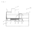
- Fig. 1 is a schematic diagram illustrating an example of installation of an air-conditioning apparatus 100 according to an embodiment of the present invention.
- the air-conditioning apparatus 100 includes a refrigeration cycle in which refrigerant is circulated. For each of indoor units 2a to 2d, a cooling mode or a heating mode can be freely selected as an operation mode.
- a single-component refrigerant such as R-22, R-32, and R-134a
- a near-azeotropic refrigerant mixture such as R-410A and R-404A
- the air-conditioning apparatus 100 includes a heat source-side refrigerant circuit A using the natural refrigerant (hereinafter also referred to as "primary loop") and a heat medium circuit B using water or the like as a heat medium (hereinafter also referred to as "secondary loop”) (see Fig. 2 ).
- primary loop the natural refrigerant
- secondary loop a heat medium circuit B using water or the like as a heat medium
- heat source-side refrigerant a method (indirect method) of indirectly using the refrigerant (hereinafter referred to as "heat source-side refrigerant"
- heat source-side refrigerant refrigerant
- cooling energy or heating energy stored in the heat source-side refrigerant is transferred to refrigerant (hereinafter referred to as "heat medium") different from the heat source-side refrigerant so that an air-conditioned space is cooled or heated with the cooling energy or heating energy stored in the heat medium.
- heat medium refrigerant
- the cooling energy or the heating energy can be stored in the heat medium.
- the air-conditioning apparatus 100 includes one outdoor unit 1 serving as a heat source apparatus, a plurality of the indoor units 2a to 2d (hereinafter also referred to simply as "indoor units 2"), and a heat medium relay unit 3 interposed between the outdoor unit 1 and the indoor units 2.
- the heat medium relay unit 3 exchanges heat between the heat source-side refrigerant and the heat medium.
- the outdoor unit 1 and the heat medium relay unit 3 are connected to each other by refrigerant pipes 4 through which the heat source-side refrigerant is circulated.
- the heat medium relay unit 3 and the indoor units 2 are connected to each other by heat medium pipes 5 through which the heat medium is circulated. Further, the cooling energy or heating energy generated by the outdoor unit 1 is delivered to the indoor units 2 through the heat medium relay unit 3.
- the outdoor unit 1 is generally arranged in an outdoor space 6, which is a space outside of a structure 9 such as an building (for example, on a rooftop), and supplies the cooling energy or heating energy to the indoor units 2 through the heat medium relay unit 3.
- the indoor units 2 are arranged at positions at which cooling air or heating air can be supplied to an indoor space 7 as a space inside the structure 9 (residential room, for example), and supply the cooling air or heating air to the indoor space 7 as the air-conditioned space.
- the heat medium relay unit 3 is arranged as a casing independent of the outdoor unit 1 and the indoor units 2 and is installed at a position different from the outdoor space 6 and the indoor space 7.
- the heat medium relay unit 3 is connected to the outdoor unit 1 through the refrigerant pipes 4 and to the indoor units 2 through the heat medium pipes 5 so as to transfer the cooling energy or heating energy supplied from the outdoor unit 1 to the indoor units 2.
- the outdoor unit 1 and the heat medium relay unit 3 are connected through the two refrigerant pipes 4, whereas the heat medium relay unit 3 and each of the indoor units 2a to 2d are connected through the two heat medium pipes 5.
- each of the units (outdoor unit 1, indoor units 2, and heat medium relay unit 3) are connected through the refrigerant pipes 4 and the heat medium pipes 5. As a result, construction is facilitated.
- the heat medium relay unit 3 may also be installed in a shared space where an elevator is installed.
- ceiling cassette type indoor units are illustrated as an example of the indoor units 2, the indoor units are not limited thereto.
- any other types of the indoor unit such as a ceiling-concealed indoor unit or a ceiling-suspended indoor unit may be used as the indoor units 2 as long as heating air or cooling air can be blown into the indoor space 7 directly or through a duct.
- the heat medium relay unit 3 may also be installed in the vicinity of the outdoor unit 1.
- delivery power for the heat medium is significantly increased. Therefore, it should be noted that energy saving effects are weakened.
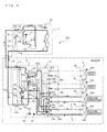
- Fig. 2 illustrates a first refrigerant circuit configuration example of the air-conditioning apparatus 100 according to the embodiment of the present invention.
- the outdoor unit 1 and intermediate heat exchangers 15a and 15b included in the heat medium relay unit 3 are connected to each other through the refrigerant pipes 4. Further, the indoor units 2 and the intermediate heat exchangers 15a and 15b are connected to each other through the heat medium pipes 5.
- a compressor 10 for compressing the refrigerant a first refrigerant flow switching device 11 constructed of a four-way valve or the like, a heat source-side heat exchanger 12 functioning as an evaporator or a condenser, and an accumulator 19 for accumulating surplus refrigerant therein are mounted and connected by the refrigerant pipes 4.
- the outdoor unit 1 includes check valves 13a to 13d, which can set a direction of a flow of the heat source-side refrigerant to be controlled to flow into the heat medium relay unit 3 constant regardless of a required operation for the indoor units 2.
- the check valve 13d is arranged on the refrigerant pipe 4 between the intermediate heat exchangers 15a and 15b (hereinafter sometimes referred to simply as "intermediate heat exchangers 15") and the first refrigerant flow switching device 11, the check valve 13b is arranged on a first connection pipe 4a, the check valve 13c is arranged on a second connection pipe 4b, and the check valve 13a is arranged on the refrigerant pipe 4 between the heat source-side heat exchanger 12 and the intermediate heat exchangers 15a and 15b.
- the compressor 10 sucks the heat source-side refrigerant, and compresses the heat source-side refrigerant into a high-temperature and high-pressure state.
- the compressor 10 may be a capacity-controllable inverter compressor or the like.
- the first refrigerant flow switching device 11 switches a flow of the heat source-side refrigerant between a flow of the heat source-side refrigerant during a heating operation mode (during a heating only operation mode and a heating main operation mode) and a flow of the heat source-side refrigerant during a cooling operation mode (during a cooling only operation mode and a cooling main operation mode).
- the heat source-side heat exchanger 12 functions as the evaporator during the heating operation and functions as the condenser during the cooling operation, and exchanges heat between air supplied from an air sending device such as a fan (not shown) and the heat source-side refrigerant.
- the cooling only operation mode is a mode in which all the running indoor units 2 execute the cooling operation
- the heating only operation mode is a mode in which all the running indoor units 2 execute the heating operation
- the cooling main operation mode is a cooling and heating mixed operation mode in which the cooling operation and the heating operation are both executed and a cooling load is larger
- the heating main operation mode is similarly a cooling and heating mixed operation mode in which a heating load is larger.
- the accumulator 19 is arranged on a suction side of the compressor 10 and has a function of accumulating the surplus refrigerant therein and a function of separating liquid refrigerant and gas refrigerant from each other. Note that, the accumulator 19 may be any reservoir as long as the surplus refrigerant can be accumulated therein.
- a second pressure sensor 37 and a third pressure sensor 38 which are pressure detection devices, are arranged in the front and back of the compressor 10.
- a refrigerant flow rate from the compressor 10 can be calculated based on a rotation speed of the compressor 10 and detection values of the second pressure sensor 37 and the third pressure sensor 38.
- use-side heat exchangers 26a to 26d are respectively mounted.
- the use-side heat exchangers 26 are connected to heat medium flow control devices 25a to 25d (hereinafter also referred to simply as “heat medium flow control devices 25”) and second heat medium flow switching devices 23a to 23d (hereinafter also referred to simply as “second heat medium flow switching devices 23”), which are included in the heat medium relay unit 3, through the heat medium pipes 5.
- the use-side heat exchangers 26 exchange the heat between the air supplied by the air sending device such as the fan (not shown) and the heat medium to generate cooling air or heating air to be supplied to the indoor space 7.
- sucked-air temperature detection devices 39a to 39d for detecting a suction temperature are respectively arranged in the indoor units 2a to 2d.
- the heat medium relay unit 3 includes the two intermediate heat exchangers 15a and 15b (hereinafter also referred to simply as “intermediate heat exchangers 15") for exchanging heat between the refrigerant and the heat medium, two expansion devices 16a and 16b (hereinafter also referred to simply as “expansion devices 16") for decompressing the refrigerant, two opening and closing devices 17a and 17b (hereinafter also referred to simply as “opening and closing devices 17”) for opening and closing passages of the refrigerant pipes 4, two second refrigerant flow switching devices 18a and 18b (hereinafter also referred to simply as “second refrigerant flow switching devices 18") for switching the refrigerant passage, two pumps 21 a and 21 b (hereinafter also referred to simply as “pumps 21 ”) for circulating the heat medium, four first heat medium flow switching devices 22a to 22d (hereinafter also referred to simply as “first heat medium flow switching devices 22”), each being connected to one of the heat medium pipes 5, the four second
- the two intermediate heat exchangers 15a and 15b function as condensers (radiators) or evaporators, and exchange heat between the heat source-side refrigerant and the heat medium, to thereby transfer the cooling energy or heating energy, which is generated by the outdoor unit 1 and stored in the heat source-side refrigerant, to the heat medium.
- the intermediate heat exchanger 15a is arranged between the expansion device 16a and the second refrigerant flow switching device 18a in the heat source-side refrigerant circuit A and serves to cool the heat medium during the cooling and heating mixed operation mode.
- the intermediate heat exchanger 15b is arranged between the expansion device 16b and the second refrigerant flow switching device 18b in the heat source-side refrigerant circuit A and serves to heat the heat medium during the cooling and heating mixed operation mode.
- the intermediate heat exchangers 15a and 15b only need to be, for example, double-pipe heat exchangers or plate heat exchangers.
- the two expansion devices 16a and 16b function as pressure reducing valves and expansion valves and decompress the heat source-side refrigerant to expand the heat source-side refrigerant.
- the expansion device 16a is arranged on an upstream side of the intermediate heat exchanger 15a in the flow of the heat source-side refrigerant during the cooling only operation mode.
- the expansion device 16b is arranged on an upstream side of the intermediate heat exchanger 15b in the flow of the heat source-side refrigerant during the cooling only operation mode. Note that, the two expansion devices 16 only need to be devices capable of variably controlling their opening degrees, such as electronic expansion valves.
- the two opening and closing devices 17a and 17b open and close the refrigerant pipes 4, and only need to be two-way valves or the like.
- the two second refrigerant flow switching devices 18a and 18b are four-way valves and switch the flow of the heat source-side refrigerant in accordance with the operation mode.
- the second refrigerant flow switching device 18a is arranged on a downstream side of the intermediate heat exchanger 15a in the flow of the heat source-side refrigerant during the cooling only operation mode.
- the second refrigerant flow switching device 18b is arranged on a downstream side of the intermediate heat exchanger 15b in the flow of the heat source-side refrigerant during the cooling only operation mode.
- the two pumps 21 a and 21 b circulate the heat medium in the heat medium pipes 5.
- the pump 21 a is arranged on the heat medium pipe 5 between the intermediate heat exchanger 15a and the second heat medium flow switching devices 23.
- the pump 21 b is arranged on the heat medium pipe 5 between the intermediate heat exchanger 15b and the second heat medium flow switching devices 23.
- the two pumps 21 only need to be, for example, capacity-controllable pumps. Note that, the pump 21 a may be arranged on the heat medium pipe 5 between the intermediate heat exchanger 15a and the first heat medium flow switching devices 22, whereas the pump 21 b may be arranged on the heat medium pipe 5 between the intermediate heat exchanger 15b and the first heat medium flow switching devices 22.
- the four first heat medium flow switching devices 22a to 22d are three-way valves or the like and switch the passage of the heat medium.
- the first heat medium flow switching devices 22 are arranged in the number in accordance with the number of the installed indoor units 2 (four in this embodiment).
- one way is connected to the intermediate heat exchanger 15a
- another way is connected to the intermediate heat exchanger 15b
- the remaining way is connected to the heat medium flow control device 25.
- the first heat medium flow switching devices 22 are arranged on an outlet side of the heat medium passages of the use-side heat exchangers 26.
- the first heat medium flow switching devices 22a to 22d are arranged in order of the first heat medium flow switching devices 22a, 22b, 22c, and 22d from the bottom of the drawing sheet so as to correspond to the indoor units 2a to 2d, and are illustrated as being arranged in the heat medium relay unit 3. However, a larger number thereof may be arranged.
- the four second heat medium flow switching devices 23a to 23d are three-way valves or the like and switch the passage of the heat medium.
- the second heat medium flow switching devices 23 are arranged in the number in accordance with the number of the installed indoor units 2 (four in this embodiment).
- one way is connected to the intermediate heat exchanger 15a
- another way is connected to the intermediate heat exchanger 15b
- the remaining way is connected to the use-side heat exchanger 26.
- the second heat medium flow switching devices 23 are arranged on an inlet side of the heat medium passages of the use-side heat exchangers 26.
- the second heat medium flow switching devices 23a to 23d are arranged in order of the second heat medium flow switching devices 23a, 23b, 23c, and 23d from the bottom of the drawing sheet so as to correspond to the indoor units 2a to 2d, and are illustrated as being arranged in the heat medium relay unit 3. However, a larger number thereof may be arranged.
- the four heat medium flow control devices 25a to 25d are two-way valves or the like, each capable of controlling the opening area, and control the flow rate of the heat medium flowing through the heat medium pipes 5.
- the heat medium flow control devices 25 are arranged in the number in accordance with the number of the installed indoor units 2 (four in this embodiment).
- One way of each of the heat medium flow control devices 25 is connected to the use-side heat exchanger 26, whereas another way thereof is connected to the first heat medium flow switching device 22.
- the heat medium flow control devices 25 are arranged on the outlet side of the heat medium passages of the use-side heat exchangers 26.
- the heat medium flow control devices 25a to 25d are arranged in order of the heat medium flow control devices 25a, 25b, 25c, and 25d from the bottom of the drawing sheet so as to correspond to the indoor units 2a to 2d, and are illustrated as being arranged in the heat medium relay unit 3. However, a larger number thereof may be arranged. Further, the heat medium flow control devices 25 may be arranged on the inlet side of the heat medium passages of the use-side heat exchangers 26.
- the two relief valves 60a and 60b are respectively arranged on the heat medium pipes 5 on an outlet side of the pumps 21 a and 21 b, and are actuated to expel the heat medium out of the system when the pressure in the secondary loop increases to a predetermined value (working pressure).
- the working pressure of the relief valves 60 is determined based on the kind of heat source-side refrigerant and the kind of heat medium.
- Cv value (Cv[60a]+Cv[60b]) which is a coefficient indicating a flow characteristic of the relief valves 60, is expressed as follows.
- Cv 60 ⁇ a + Cv 60 ⁇ b Cv ⁇ 1 ⁇ P ⁇ 1 - P ⁇ 2 1 / 2 / P ⁇ 2 1 / 2
- Cv1 is about 1 mm 2 in a case of a pin hole due to the corrosion of a copper pipe, and thus the Cv value of the relief valves 60, which corresponds to the sum of Cv[60a]+Cv[60b], is required to be 3 mm 2 or larger in total.
- the working pressure of the relief valves 60 is determined in accordance with the maximum pressure of the heat medium alone. Then, when the heat source-side refrigerant leaks into the secondary loop, the relief valves 60 are actuated along with a sudden increase in pressure in the secondary loop. However, there is a risk in that the increase in pressure is not fully relieved and the pressure exceeds withstanding pressures of components used in the secondary loop, resulting in damage to the components. Therefore, also in consideration of a pressure different for each kind of heat source-side refrigerant, the working pressure of the relief valves 60 is determined based on the kind of heat medium and the kind of heat source-side refrigerant.
- a size of each of the relief valves 60 is selected in accordance with the maximum pressure of the heat medium and the maximum pressure of the heat source-side refrigerant to determine (control) an expelling flow rate out of the system. In this manner, the pressure in the secondary loop is kept at an appropriate pressure.
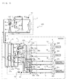
- Fig. 3 illustrates a second refrigerant circuit configuration example of the air-conditioning apparatus 100 according to the embodiment of the present invention.
- the relief valves 60a and 60b are respectively arranged on the heat medium pipes 5 on the outlet side of the pumps 21 a and 21 b. As illustrated in Fig. 3 , however, the relief valve 60b may be omitted by connecting the heat medium pipe 5 on a discharge side of the pump 21 a and the heat medium pipe 5 on a discharge side of the pump 21 b through a narrow pipe. Further, a heat medium pressure detection device 62 for detecting the pressure in the secondary loop may be arranged on the heat medium pipe 5 on the outlet side of the pump 21 b.
- the heat medium relay unit 3 includes, as illustrated in Figs. 2 and 3 , various types of detection means such as two first temperature sensors 31 a and 31 b (hereinafter also referred to simply as “first temperature sensors 31 "), four second temperature sensors 34a to 34d (hereinafter also referred to simply as “second temperature sensors 34"), four third temperature sensors 35a to 35d (hereinafter also referred to simply as “third temperature sensors 35”), a fourth temperature sensor 50, and a first pressure sensor 36.
- various types of detection means such as two first temperature sensors 31 a and 31 b (hereinafter also referred to simply as “first temperature sensors 31 "), four second temperature sensors 34a to 34d (hereinafter also referred to simply as “second temperature sensors 34”), four third temperature sensors 35a to 35d (hereinafter also referred to simply as “third temperature sensors 35”), a fourth temperature sensor 50, and a first pressure sensor 36.
- Information pieces detected by the above-mentioned detection means are transmitted to a controller 52 (note that, the controller 52 is described later) for collectively controlling the operation of the air-conditioning apparatus 100, and are used for controlling a driving frequency of the compressor 10, a rotation speed of each of the air sending devices (not shown) arranged in the vicinity of the heat source-side heat exchanger 12 and in the vicinity of the use-side heat exchangers 26, switching of the first refrigerant flow switching device 11, a driving frequency of the pumps 21, switching of the second refrigerant flow switching devices 18, and the like.
- a controller 52 for collectively controlling the operation of the air-conditioning apparatus 100, and are used for controlling a driving frequency of the compressor 10, a rotation speed of each of the air sending devices (not shown) arranged in the vicinity of the heat source-side heat exchanger 12 and in the vicinity of the use-side heat exchangers 26, switching of the first refrigerant flow switching device 11, a driving frequency of the pumps 21, switching of the second refrigerant flow switching devices 18, and the like.
- a refrigerant leakage detection device 61 is arranged on the intermediate heat exchangers 15 or in the vicinity thereof in addition to the above-mentioned detection means. Information therefrom is input to a computing device 52a described below.
- the controller 52 is a microcomputer or the like and calculates an evaporating temperature, a condensing temperature, a saturation temperature, a degree of superheat, and a degree of subcooling based on the results of calculation by the computing device 52a. Then, based on the results of calculation, the controller 52 controls an opening degree of each of the expansion devices 16, the rotation speed of the compressor 10, a speed of each of the fans for the heat source-side heat exchanger 12 and the use-side heat exchangers 26 (including ON/OFF), and the like so that performance of the air-conditioning apparatus 100 is maximized.
- the controller 52 controls a driving frequency of the compressor 10, a rotation speed of the air sending devices (including ON/OFF), switching of the first refrigerant flow switching device 11, driving of the pumps 21, the opening degree of each of the expansion devices 16, opening and closing of the opening and closing devices 17, switching of the second refrigerant flow switching devices 18, switching of the first heat medium flow switching devices 22, switching of the second heat medium flow switching devices 23, an opening degree of each of the heat medium flow control devices 25, and the like.
- the controller 52 collectively controls various types of equipment so as to execute each of the operation modes described later.
- a controller 57 is also arranged in the outdoor unit 1, and controls actuators of the outdoor unit 1 based on the information pieces transmitted from the controller 52 of the heat medium relay unit 3.
- controller 52 of the heat medium relay unit 3 is described as a component independent of a computing device 57a arranged in the outdoor unit 1 in this embodiment, the controller 52 and the computing device 57a may be the same component.
- the two first temperature sensors 31 a and 31 b detect a temperature of the heat medium flowing out of the intermediate heat exchangers 15, specifically, the heat medium at outlets of the intermediate heat exchangers 15, and only need to be, for example, thermistors.
- the first temperature sensor 31 a is arranged on the heat medium pipe 5 on an inlet side of the pump 21 a.
- the first temperature sensor 31 b is arranged on the heat medium pipe 5 on an inlet side of the pump 21 b.
- the four second temperature sensors 34a to 34d are respectively arranged between the first heat medium flow switching devices 22 and the heat medium flow control devices 25, and detect the temperature of the heat medium flowing out of the use-side heat exchangers (or heat recovery heat exchangers) 26.
- the four second temperature sensors 34a to 34d only need to be thermistors.
- the second temperature sensors 34 are arranged in the number in accordance with the number of the installed indoor units 2 (four in this embodiment). Note that, the second temperature sensors 34a to 34d are illustrated as the second temperature sensors 34a, 34b, 34c, and 34d from the bottom of the drawing sheet so as to correspond to the indoor units 2.
- the four third temperature sensors 35a to 35d are arranged on an inlet side or an outlet side of the intermediate heat exchangers 15 for the heat source-side refrigerant, and detect the temperature of the heat source-side refrigerant flowing into the intermediate heat exchangers 15 or the temperature of the heat source-side refrigerant flowing out of the intermediate heat exchangers 15.
- the four third temperature sensors 35a to 35d only need to be thermistors.
- the third temperature sensor 35a is arranged between the intermediate heat exchanger 15a and the second refrigerant flow switching device 18a.
- the third temperature sensor 35b is arranged between the intermediate heat exchanger 15a and the expansion device 16a.
- the third temperature sensor 35c is arranged between the intermediate heat exchanger 15b and the second refrigerant flow switching device 18b.
- the third temperature sensor 35d is arranged between the intermediate heat exchanger 15b and the expansion device 16b.
- the fourth temperature sensor 50 obtains the temperature information that is used to calculate the evaporating temperature and a dew-point temperature, and is arranged between the expansion devices 16a and 16b.
- the first pressure sensor 36 obtains the pressure information for conversion into the saturation temperature that is used to control the opening degrees of the expansion devices 16, and is arranged between the intermediate heat exchanger 15b and the expansion device 16b.
- the heat medium pipes 5 for circulating the heat medium include the heat medium pipes 5 connected to the intermediate heat exchanger 15a and the heat medium pipes 5 connected to the intermediate heat exchanger 15b, each of which are split in accordance with the number of the indoor units 2 connected to the heat medium relay unit 3 (split into four branches in this embodiment). Further, the heat medium pipes 5 connected to the inlet side of the intermediate heat exchanger 15a and the heat medium pipes 5 connected to the inlet side of the intermediate heat exchanger 15b are respectively connected by the first heat medium flow switching devices 22, whereas the heat medium pipes 5 connected to the outlet side of the intermediate heat exchanger 15a and the heat medium pipes 5 connected to the outlet side of the intermediate heat exchanger 15b are respectively connected by the second heat medium flow switching devices 23.
- the compressor 10 In the air-conditioning apparatus 100, the compressor 10, the first refrigerant flow switching device 11, the heat source-side heat exchanger 12, the opening and closing devices 17, the expansion devices 16, the heat source-side refrigerant passage in the intermediate heat exchanger 15a, the second refrigerant flow switching devices 18, and the accumulator 19 are connected by the refrigerant pipes 4 to form the heat source-side refrigerant circuit A.
- the heat medium passage in the intermediate heat exchanger 15a, the pumps 21, the second heat medium flow switching devices 23, the use-side heat exchangers 26, the heat medium flow control devices 25, and the first heat medium flow switching devices 22 are connected by the heat medium pipes 5 to form the heat medium circuit B.
- the plurality of the use-side heat exchangers 26 are respectively connected in parallel to the intermediate heat exchangers 15a and 15b to form the heat medium circuit B having a plurality of systems.
- the outdoor unit 1 and the heat medium relay unit 3 are connected through the intermediate heat exchangers 15a and 15b arranged in the heat medium relay unit 3, whereas the heat medium relay unit 3 and the indoor units 2 are similarly connected through the intermediate heat exchangers 15a and 15b.
- the heat source-side refrigerant circulating through the heat source-side refrigerant circuit A through the intermediate heat exchangers 15a and 15b and the heat medium circulating through the heat medium circuit B exchange heat.
- the air-conditioning apparatus 100 Based on an instruction from each of the indoor units 2, the air-conditioning apparatus 100 enables the indoor units 2 to perform the cooling operation or the heating operation. Specifically, the air-conditioning apparatus 100 enables all the indoor units 2 to perform the same operation and also enables each of the indoor units 2 to perform a different operation.
- the number of operation modes to be executed by the air-conditioning apparatus 100 is four, specifically, the cooling only operation mode, the heating only operation mode, the cooling main operation mode, and the heating main operation mode. Now, each of the operation modes is described with the flows of the heat source-side refrigerant and the heat medium.
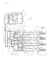
- Fig. 4 is a refrigerant circuit diagram illustrating the flow of the refrigerant during the cooling only operation mode of the air-conditioning apparatus 100 illustrated in Fig. 2 .
- the cooling only operation mode is described taking as an example a case where a cooling load is generated in the indoor unit 2a corresponding to the use-side heat exchanger 26a and the indoor unit 2b corresponding to the use-side heat exchanger 26b.
- the pipes indicated by the thick lines are the pipes through which the refrigerant (heat source-side refrigerant and heat medium) flows.
- a direction of the flow of the heat source-side refrigerant is indicated by the solid arrows, whereas a direction of the flow of the heat medium is indicated by the dashed arrows.
- the first refrigerant flow switching device 11 in the outdoor unit 1 is switched so that the heat source-side refrigerant discharged from the compressor 10 flows into the heat source-side heat exchanger 12.
- the pumps 21 a and 21 b are driven to open the heat medium flow control devices 25a and 25b and to close the heat medium flow control devices 25c and 25d so that the heat medium circulates between the intermediate heat changers 15a and 15b and the use-side heat exchangers 26a and 26b.
- Low-temperature and low-pressure refrigerant is compressed by the compressor 10 and discharged as high-temperature and high-pressure gas refrigerant.
- the high-temperature and high-pressure gas refrigerant discharged from the compressor 10 flows into the heat source-side heat exchanger 12 through the first refrigerant flow switching device 11, and then turns into high-pressure liquid refrigerant in the heat source-side heat exchanger 12 while rejecting heat to the outdoor air.
- the high-pressure refrigerant flowing out of the heat source-side heat exchanger 12 passes through the check valve 13a to flow out of the outdoor unit 1, and then passes through the refrigerant pipe 4 to flow into the heat medium relay unit 3.
- the opening and closing device 17a After passing through the opening and closing device 17a, the high-pressure refrigerant flowing into the heat medium relay unit 3 is split into a flow toward the expansion device 16a and a flow toward the expansion device 16b. Then, the refrigerant is expanded by the expansion devices 16a and 16b to turn into low-temperature and low-pressure two-phase refrigerant. Note that, the opening and closing device 17b is closed.
- the two-phase refrigerant flows into each of the intermediate heat exchangers 15a and 15b functioning as the evaporators and takes away heat from the heat medium circulating through the heat medium circuit B.
- the two-phase refrigerant turns into low-temperature and low-pressure gas refrigerant while cooling the heat medium.
- the gas refrigerant flowing out of the intermediate heat exchangers 15a and 15b flows out of the heat medium relay unit 3 through the second refrigerant flow switching devices 18a and 18b, and then passes through the refrigerant pipe 4 to flow into the outdoor unit 1 again.
- the refrigerant flowing into the outdoor unit 1 passes through the check valve 13d to be sucked into the compressor 10 again through the first refrigerant flow switching device 11 and the accumulator 19.
- the second refrigerant flow switching devices 18a and 18b are held in communication with low-pressure pipes. Further, the opening degree of the expansion device 16a is controlled so that superheat (degree of superheat) determined as a difference between the temperature detected by the third temperature sensor 35a and the temperature detected by the third temperature sensor 35b becomes constant. Similarly, the opening degree of the expansion device 16b is controlled so that superheat determined as a difference between the temperature detected by the third temperature sensor 35c and the temperature detected by the third temperature sensor 35d becomes constant.
- the cooing energy of the heat source-side refrigerant is transferred to the heat medium in each of the intermediate heat exchangers 15a and 15b.
- the cooled heat medium is controlled to flow through the heat medium pipes 5 by the pumps 21 a and 21 b.
- the heat medium which is pressurized by the pumps 21 a and 21 b to flow out thereof, flows into the use-side heat exchangers 26a and 26b through the second heat medium flow switching devices 23a and 23b. Then, the heat medium takes away heat from the indoor air in the use-side heat exchangers 26a and 26b to cool the indoor space 7.
- the heat medium flows out of the use-side heat exchangers 26a and 26b to flow into the heat medium flow control devices 25a and 25b.
- the heat medium flows into the use-side heat exchangers 26a and 26b.
- the heat medium flowing out of the heat medium flow control devices 25a and 25b passes through the first heat medium flow switching devices 22a and 22b to flow into the intermediate heat exchangers 15a and 15b, and is then sucked into the pumps 21 a and 21 b again.
- the heat medium flows in a direction to the first heat medium flow switching devices 22a and 22b from the second heat medium flow switching devices 23a and 23b through the heat medium flow control devices 25a and 25b.
- the air conditioning load required for the indoor space 7 can be achieved by performing control so that a difference between the temperature detected by the first temperature sensor 31 a or the temperature detected by the first temperature sensor 31 b and the temperature detected by the second temperature sensor 34a (or the second temperature sensor 34b) is kept as a target value.
- As outlet temperatures of the intermediate heat exchangers 15a and 15b any of the temperatures obtained by the first temperature sensors 31 a and 31 b or an average temperature thereof may be used.
- the opening degree of each of the first heat medium flow switching devices 22 and the second heat medium flow switching devices 23 is set to an intermediate opening degree so that the passages to both the intermediate heat exchangers 15a and 15b are secured.
- the heat medium When the cooling only operation mode is executed, the heat medium is not required to be controlled to flow to the use-side heat exchangers 26 without a heat load (including a thermostat-off state). Therefore, the passages are closed by the heat medium flow control devices 25 so that the heat medium does not flow to the use-side heat exchangers 26.
- the heat medium is controlled to flow through the use-side heat exchangers 26a and 26b because of the presence of heat loads, whereas the use-side heat exchangers 26c and 26d are not actuated. Therefore, the corresponding heat medium flow control device 25c and heat medium flow control device 25d are fully closed.
- the heat medium flow control device 25 When the heat load is generated in the use-side heat exchangers 26 or a heat recovery device is operated, the heat medium flow control device 25 only needs to be opened to allow the heat medium to circulate.
- the refrigerant whose temperature is detected by the fourth temperature sensor 50 is the liquid refrigerant. Based on the temperature information thereof, a liquid inlet enthalpy is calculated by the computing device 52a. Further, a temperature in the low-pressure two-phase temperature state is detected by the third temperature sensor 35d. Based on the temperature information thereof, a saturated liquid enthalpy and a saturated gas enthalpy are calculated by the computing device 52a. Based on the information pieces described above, an evaporating temperature Te* and a dew-point temperature Tdew* are determined by a method described later.
- Fig. 5 is a refrigerant circuit diagram illustrating the flow of the refrigerant during the heating only operation mode of the air-conditioning apparatus 100 illustrated in Fig. 2 .
- the heating only operation mode is described taking as an example a case where a heating load is generated in the use-side heat exchangers 26a and 26b.
- the pipes indicated by the thick lines are the pipes through which the refrigerant flows.
- the direction of the flow of the heat source-side refrigerant is indicated by the solid arrows, whereas the direction of the flow of the heat medium is indicated by the dashed arrows.
- the first refrigerant flow switching device 11 in the outdoor unit 1 is switched so that the heat source-side refrigerant discharged from the compressor 10 flows into the heat medium relay unit 3 without passing through the heat source-side heat exchanger 12.
- the pumps 21 a and 21 b are driven to open the heat medium flow control devices 25a and 25b and to close the heat medium flow control devices 25c and 25d so that the heat medium circulates between the intermediate heat changers 15a and 15b and the use-side heat exchangers 26a and 26b.
- Low-temperature and low-pressure refrigerant is compressed by the compressor 10 and discharged as high-temperature and high-pressure gas refrigerant.
- the high-temperature and high-pressure gas refrigerant discharged from the compressor 10 passes through the first refrigerant flow switching device 11 and the check valve 13b to flow out of the outdoor unit 1.
- the high-temperature and high-pressure gas refrigerant flowing out of the outdoor unit 1 passes through the refrigerant pipe 4 to flow into the heat medium relay unit 3.
- the high-temperature and high-pressure gas refrigerant flowing into the heat medium relay unit 3 is split into the flow toward the second refrigerant flow switching device 18a and the flow toward the second refrigerant flow switching device 18b.
- the gas refrigerant passes respectively through the second refrigerant flow switching device 18a and the second refrigerant flow switching device 18b to flow into the intermediate heat exchangers 15a and 15b.
- the high-temperature and high-pressure gas refrigerant flowing into the intermediate heat exchangers 15a and 15b turns into high-pressure liquid refrigerant while rejecting heat to the heat medium circulating through the heat medium circuit B.
- the liquid refrigerant flowing out of the intermediate heat exchangers 15a and 15b is expanded by the expansion devices 16a and 16b to turn into low-temperature and low-pressure two-phase refrigerant.
- the two-phase refrigerant passes through the opening and closing device 17b to flow out of the heat medium relay unit 3, and then flows into the outdoor unit 1 again through the refrigerant pipe 4. Note that, the opening and closing device 17a is closed.
- the refrigerant flowing into the outdoor unit 1 passes through the check valve 13c to flow into the heat source-side heat exchanger 12 functioning as the evaporator. Then, the refrigerant flowing into the heat source-side heat exchanger 12 takes away heat from the outdoor air in the heat source-side heat exchanger 12 to turn into low-temperature and low-pressure gas refrigerant. The low-temperature and low-pressure gas refrigerant flowing out of the heat source-side heat exchanger 12 is sucked into the compressor 10 again through the first refrigerant flow switching device 11 and the accumulator 19.
- the second refrigerant flow switching devices 18a and 18b are held in communication with high-pressure pipes. Further, the opening degree of the expansion device 16a is controlled so that subcool (degree of subcooling) determined as a difference between a value determined by converting the pressure detected by the first pressure sensor 36 into a saturation temperature and the temperature detected by the third temperature sensor 35b becomes constant. Similarly, the opening degree of the expansion device 16b is controlled so that subcool determined as a difference between the value determined by converting the pressure detected by the first pressure sensor 36 into the saturation temperature and the temperature detected by the third temperature sensor 35d becomes constant. Note that, in a case where a temperature at an intermediate position in the intermediate heat exchangers 15 can be measured, the temperature at the intermediate position may be used in place of the first pressure sensor 36. As a result, the system can be constructed at low cost.
- the heating energy of the heat source-side refrigerant is transferred to the heat medium in each of the intermediate heat exchangers 15a and 15b.
- the heated heat medium is controlled to flow through the heat medium pipes 5 by the pumps 21 a and 21 b.
- the heat medium which is pressurized by the pumps 21 a and 21 b to flow out thereof, flows into the use-side heat exchangers 26a and 26b through the second heat medium flow switching devices 23a and 23b. Then, the heat medium rejects heat to the indoor air in the use-side heat exchangers 26a and 26b to heat the indoor space 7.
- the heat medium flows out of the use-side heat exchangers 26a and 26b to flow into the heat medium flow control devices 25a and 25b.
- the heat medium flows into the use-side heat exchangers 26a and 26b.
- the heat medium flowing out of the heat medium flow control devices 25a and 25b passes through the first heat medium flow switching devices 22a and 22b to flow into the intermediate heat exchangers 15a and 15b, and is then sucked into the pumps 21 a and 21 b again.
- the heat medium flows in the direction to the first heat medium flow switching devices 22a and 22b from the second heat medium flow switching devices 23a and 23b through the heat medium flow control devices 25a and 25b.
- the air conditioning load required for the indoor space 7 can be achieved by performing control so that the difference between the temperature detected by the first temperature sensor 31 a or the temperature detected by the first temperature sensor 31 b and the temperature detected by the second temperature sensor 34a or 34b is kept as a target value.
- the outlet temperatures of the intermediate heat exchangers 15a and 15b any of the temperatures obtained by the first temperature sensors 31 a and 31 b or an average temperature thereof may be used.
- the opening degree of each of the first heat medium flow switching devices 22 and the second heat medium flow switching devices 23 is set to an intermediate opening degree so that the passages to both the intermediate heat exchangers 15a and 15b are secured.
- the use-side heat exchanger 26 needs to essentially be controlled based on a difference between a temperature at the inlet and a temperature at the outlet.
- the heat medium temperature on the inlet side of the use-side heat exchanger 26 is substantially the same as the temperature detected by the first temperature sensor 31 b. Therefore, by using the first temperature sensor 31 b, the number of temperature sensors can be reduced. As a result, the system can be constructed at low cost.
- Fig. 6 is a refrigerant circuit diagram illustrating the flow of the refrigerant during the cooling main operation mode of the air-conditioning apparatus 100 illustrated in Fig. 2 .
- the cooling main operation mode is described taking as an example a case where the heating load is generated in the use-side heat exchanger 26d and the cooling load is generated in the use-side heat exchangers 26a to 26c.
- the pipes indicated by the thick lines are the pipes through which the refrigerant (heat source-side refrigerant and heat medium) circulates.
- the direction of the flow of the heat source-side refrigerant is indicated by the solid arrows, whereas the direction of the flow of the heat medium is indicated by the dashed arrows.
- the first refrigerant flow switching device 11 in the outdoor unit 1 is switched so that the heat source-side refrigerant discharged from the compressor 10 flows into the heat source-side heat exchanger 12.
- the pumps 21 a and 21 b are driven to open the heat medium flow control devices 25a to 25d so that the heat medium circulates between the intermediate heat changer 15a and the use-side heat exchangers 26a to 26c and between the intermediate heat changer 15b and the use-side heat exchanger 26d.
- Low-temperature and low-pressure refrigerant is compressed by the compressor 10 and discharged as high-temperature and high-pressure gas refrigerant.
- the high-temperature and high-pressure gas refrigerant discharged from the compressor 10 flows into the heat source-side heat exchanger 12 through the first refrigerant flow switching device 11, and then turns into liquid refrigerant in the heat source-side heat exchanger 12 while rejecting heat to the outdoor air.
- the refrigerant flowing out of the heat source-side heat exchanger 12 flows out of the outdoor unit 1, and passes through the check valve 13a and the refrigerant pipe 4 to flow into the heat medium relay unit 3.
- the refrigerant flowing into the heat medium relay unit 3 passes through the second refrigerant flow switching device 18b to flow into the intermediate heat exchanger 15b functioning as the condenser.
- the refrigerant flowing into the intermediate heat exchanger 15b turns into refrigerant having a further lowered temperature while rejecting heat to the heat medium circulating through the heat medium circuit B.
- the refrigerant flowing out of the intermediate heat exchanger 15b is expanded by the expansion device 16b to turn into low-pressure two-phase refrigerant.
- the low-pressure two-phase refrigerant flows into the intermediate heat exchanger 15a functioning as the evaporator through the expansion device 16a.
- the low-pressure two-phase refrigerant flowing into the intermediate heat exchanger 15a takes away heat from the heat medium circulating through the heat medium circuit B to turn into low-pressure gas refrigerant while cooling the heat medium.
- the gas refrigerant flows out of the intermediate heat exchanger 15a, flows out of the heat medium relay unit 3 through the second refrigerant flow switching device 18a, and passes through the refrigerant pipe 4 to flow into the outdoor unit 1 again.
- the refrigerant flowing into the outdoor unit 1 is sucked into the compressor 10 again through the check valve 13d, the first refrigerant flow switching device 11, and the accumulator 19.
- the second refrigerant flow switching device 18a is held in communication with a low-pressure pipe, whereas the second refrigerant flow switching device 18b is held in communication with a high-pressure-side pipe.
- the opening degree of the expansion device 16b is controlled so that the superheat determined as a difference between the temperature detected by the third temperature sensor 35a and the temperature detected by the third temperature sensor 35b becomes constant.
- the expansion device 16a is fully opened, whereas the opening and closing devices 17a and 17b are closed.
- the opening degree of the expansion device 16b may be controlled so that the subcool determined as a difference between the value determined by converting the pressure detected by the first pressure sensor 36 into the saturation temperature and the temperature detected by the third temperature sensor 35d becomes constant.
- the expansion device 16b may be fully opened, while the superheat or subcool may be controlled by the expansion device 16a.
- the heating energy of the heat source-side refrigerant is transferred to the heat medium in the intermediate heat exchanger 15b.
- the heated heat medium is controlled to flow through the heat medium pipe 5 by the pump 21 b.
- the cooling energy of the heat source-side refrigerant is transferred to the heat medium in the intermediate heat exchanger 15a.
- the cooled heat medium is controlled to flow through the heat medium pipes 5 by the pump 21 a.
- the heat medium which is pressurized by the pumps 21 a and 21 b to flow out thereof, flows into the use-side heat exchangers 26a to 26d through the second heat medium flow switching devices 23a to 23d.
- the heat medium rejects heat to the indoor air in the use-side heat exchanger 26d to heat the indoor space 7. Further, the heat medium takes away heat from the indoor air in the use-side heat exchangers 26a to 26c to cool the indoor space 7. At this time, after the flow rate of the heat medium is controlled to the flow rate necessary to achieve the air conditioning load required for the interior by the functions of the heat medium flow control devices 25a to 25d, the heat medium flows into the use-side heat exchangers 26a to 26d.
- the heat medium which passes through the use-side heat exchanger 26d to have a slightly lowered temperature, passes through the heat medium flow control device 25d and the first heat medium flow switching device 22d to flow into the intermediate heat exchanger 15b, and is sucked into the pump 21 b again.
- the heat medium which passes through the use-side heat exchangers 26a to 26c to have a slightly increased temperature, passes through the heat medium flow control devices 25a to 25c and the first heat medium flow switching devices 22a to 22c to flow into the intermediate heat exchanger 15a, and is sucked into the pump 21 a again.
- the heated heat medium and the cooled heat medium are introduced into the use-side heat exchangers 26a to 26d respectively with the heating loads and cooling loads without being mixed, by the functions of the first heat medium flow switching devices 22 and the second heat medium flow switching devices 23.
- the heat medium flows in the direction to the first heat medium flow switching devices 22 from the second heat medium flow switching devices 23 through the heat medium flow control devices 25 on both the heating side and the cooling side.
- the air conditioning load required for the indoor space 7 can be achieved by controlling the difference between the temperature detected by the first temperature sensor 31 b and the temperature detected by the second temperature sensor 34d to be kept as a target value on the heating side and the difference between the temperatures detected by the second temperature sensors 34a to 34c and the temperature detected by the first temperature sensor 31 a to be kept as a target value on the cooling side.
- Fig. 7 is a refrigerant circuit diagram illustrating the flow of the refrigerant during the heating main operation mode of the air-conditioning apparatus 100 illustrated in Fig. 2 .
- the heating main operation mode is described taking as an example a case where the heating load is generated in the use-side heat exchangers 26b to 26d and the cooling load is generated in the use-side heat exchanger 26a.
- the pipes indicated by the thick lines are the pipes through which the refrigerant (heat source-side refrigerant and heat medium) circulates.
- the direction of the flow of the heat source-side refrigerant is indicated by the solid arrows, whereas the direction of the flow of the heat medium is indicated by the dashed arrows.
- the first refrigerant flow switching device 11 in the outdoor unit 1 is switched so that the heat source-side refrigerant discharged from the compressor 10 flows into the heat medium relay unit 3 without passing through the heat source-side heat exchanger 12.
- the pumps 21 a and 21 b are driven to open the heat medium flow control devices 25a to 25d so that the heat medium circulates between the intermediate heat changer 15a and the use-side heat exchanger 26a and between the intermediate heat changer 15b and the use-side heat exchangers 26b to 26d.
- Low-temperature and low-pressure refrigerant is compressed by the compressor 10 and discharged as high-temperature and high-pressure gas refrigerant.
- the high-temperature and high-pressure gas refrigerant discharged from the compressor 10 passes through the first refrigerant flow switching device 11 and the check valve 13b to flow out of the outdoor unit 1.
- the high-temperature and high-pressure gas refrigerant flowing out of the outdoor unit 1 passes through the refrigerant pipe 4 to flow into the heat medium relay unit 3.
- the high-temperature and high-pressure gas refrigerant flowing into the heat medium relay unit 3 passes through the second refrigerant flow switching device 18b to flow into the intermediate heat exchanger 15b functioning as the condenser.
- the gas refrigerant flowing into the intermediate heat exchanger 15b turns into liquid refrigerant while rejecting heat to the heat medium circulating through the heat medium circuit B.
- the refrigerant flowing out of the intermediate heat exchanger 15b is expanded by the expansion device 16b to turn into low-pressure two-phase refrigerant.
- the low-pressure two-phase refrigerant flows into the intermediate heat exchanger 15a functioning as the evaporator through the expansion device 16a.
- the low-pressure two-phase refrigerant flowing into the intermediate heat exchanger 15a takes away heat from the heat medium circulating through the heat medium circuit B to evaporate and cool the heat medium.
- the low-pressure two-phase refrigerant flows out of the intermediate heat exchanger 15a, and flows out of the heat medium relay unit 3 through the second refrigerant flow switching device 18a to flow into the outdoor unit 1 again.
- the refrigerant flowing into the outdoor unit 1 passes through the check valve 13c to flow into the heat source-side heat exchanger 12 functioning as the evaporator. Then, the refrigerant flowing into the heat source-side heat exchanger 12 takes away heat from the outdoor air in the heat source-side heat exchanger 12 to turn into low-temperature and low-pressure gas refrigerant. The low-temperature and low-pressure gas refrigerant flowing out of the heat source-side heat exchanger 12 is sucked into the compressor 10 again through the first refrigerant flow switching device 11 and the accumulator 19.
- the second refrigerant flow switching device 18a is held in communication with a low-pressure-side pipe, whereas the second refrigerant flow switching device 18b is held in communication with a high-pressure-side pipe.
- the opening degree of the expansion device 16b is controlled so that the subcool determined as the difference between the value determined by converting the pressure detected by the first pressure sensor 36 into the saturation temperature and the temperature detected by the third temperature sensor 35b becomes constant.
- the expansion device 16a is fully opened, whereas the opening and closing devices 17a and 17b are closed. Note that, the expansion device 16b may be fully opened, while the subcool may be controlled by the expansion device 16a.
- the heating energy of the heat source-side refrigerant is transferred to the heat medium in the intermediate heat exchanger 15b.
- the heated heat medium is controlled to flow through the heat medium pipes 5 by the pump 21 b.
- the cooling energy of the heat source-side refrigerant is transferred to the heat medium in the intermediate heat exchanger 15a.
- the cooled heat medium is controlled to flow through the heat medium pipe 5 by the pump 21 a.
- the heat medium which is pressurized by the pumps 21 a and 21 b to flow out thereof, flows into the use-side heat exchangers 26a to 26d through the second heat medium flow switching devices 23a to 23d.
- the heat medium takes away heat from the indoor air in the use-side heat exchanger 26a to cool the indoor space 7. Further, the heat medium rejects heat to the indoor air in the use-side heat exchangers 26b to 26d to heat the indoor space 7. At this time, after the flow rate of the heat medium is controlled to the flow rate necessary to achieve the air conditioning load required for the interior by the functions of the heat medium flow control devices 25a to 25d, the heat medium flows into the use-side heat exchangers 26a to 26d.
- the heat medium which passes through the use-side heat exchanger 26a to have a slightly increased temperature, passes through the heat medium flow control device 25a and the first heat medium flow switching device 22a to flow into the intermediate heat exchanger 15a, and is sucked into the pump 21 a again.
- the heat medium which passes through the use-side heat exchangers 26b to 26d to have a slightly lowered temperature, passes through the heat medium flow control devices 25b to 25d and the first heat medium flow switching devices 22b to 22d to flow into the intermediate heat exchanger 15b, and is sucked into the pump 21 b again.
- the heated heat medium and the cooled heat medium are introduced into the use-side heat exchangers 26a to 26d respectively with the heating loads and cooling loads without being mixed, by the functions of the first heat medium flow switching devices 22 and the second heat medium flow switching devices 23.
- the heat medium flows in the direction to the first heat medium flow switching devices 22 from the second heat medium flow switching devices 23 through the heat medium flow control devices 25 on both the heating side and the cooling side.
- the air conditioning load required for the indoor space 7 can be achieved by controlling the difference between the temperature detected by the first temperature sensor 31 b and the temperatures detected by the second temperature sensors 34b to 34d to be kept as a target value on the heating side and the difference between the temperature detected by the second temperature sensor 34a and the temperature detected by the first temperature sensor 31 a to be kept as a target value on the cooling side.
- the heat medium when the heating main operation mode is executed, the heat medium is not required to be controlled to flow to the use-side heat exchangers 26 without a heat load (including the thermostat-off state). Therefore, the passages are closed by the heat medium flow control devices 25 so that the heat medium does not flow to the use-side heat exchangers 26.
- the heat medium is controlled to flow through all the use-side heat exchangers 26a to 26d because of the presence of heat loads. However, when any one of the use-side heat exchangers 26 does not have the heat load, the corresponding one of the heat medium flow control devices 25 is fully closed.
- the heat source-side refrigerant of the primary loop flows into the secondary loop.
- the pressure in the secondary loop increases.
- the relief valves 60 are actuated to expel the heat source-side refrigerant mixed with the heat medium from the relief valves 60. Therefore, the pressure in the secondary loop can be reduced to suppress the damage to the component used in the secondary loop, which is otherwise caused by the increase in pressure, to thereby suppress the spread of the leakage of the heat source-side refrigerant.
- the working pressure of the relief valves 60 is determined based on the kind of heat medium and the kind of heat source-side refrigerant and the size of each of the relief valves 60 is selected in accordance with the maximum pressure of the heat medium and the maximum pressure of the heat source-side refrigerant to determine (control) the expelling flow rate out of the system. In this manner, the pressure in the secondary loop is kept at an appropriate pressure.
- the expelled heat source-side refrigerant and heat medium stagnate inside the heat medium relay unit 3, which is detected by the refrigerant leakage detection device 61.
- the outdoor unit 1 stopping the pumps 21 a and 21 b, and closing the heat medium flow control devices 25a to 25d, the spread of the leakage of the heat source-side refrigerant to the indoor side can be further suppressed.
- the leakage of the heat source-side refrigerant may be determined based on a change in the refrigeration cycle of the primary loop such as a reduction in the second pressure sensor 37 of the outdoor unit 1 in place of the detection by the refrigerant leakage detection device 61.
- the second pressure sensor functions as refrigerant leakage detection means.
- the heat medium pressure detection device 62 (see Fig. 3 ) for detecting the pressure in the secondary loop may be arranged to detect the leakage of the heat source-side refrigerant based on the increase in pressure in the secondary loop.
- the heat medium pressure detection device 62 functions as the refrigerant leakage detection means.
Landscapes
- Engineering & Computer Science (AREA)
- Mechanical Engineering (AREA)
- General Engineering & Computer Science (AREA)
- Chemical & Material Sciences (AREA)
- Combustion & Propulsion (AREA)
- Physics & Mathematics (AREA)
- Thermal Sciences (AREA)
- Other Air-Conditioning Systems (AREA)
- Air Conditioning Control Device (AREA)
Abstract
Description
- The present invention relates to an air-conditioning apparatus to be applied to, for example, a multi-air-conditioning apparatus for a building.
- As a related-art air-conditioning apparatus, there is given an air-conditioning apparatus including a heat source apparatus (outdoor unit) arranged outside of a building and indoor units arranged in rooms of the building as in a case of a multi-air-conditioning apparatus for a building. Refrigerant circulating through a refrigerant circuit of the air-conditioning apparatus described above rejects heat to (takes away heat from) air supplied to a heat exchanger of each of the indoor units to heat or cool the air. Then, the heated or cooled air is sent to an air-conditioned space to perform heating or cooling.
- Each of the indoor units of the multi-air-conditioning apparatus for a building described above is generally arranged for use in an indoor space where a person is present (such as an office, a residential room, or a store). Therefore, when the refrigerant leaks from the indoor unit arranged in the indoor space for some reason, there arises a problem in view of effects on a human body and safety because some kinds of refrigerant have inflammability and toxicity. Further, even when the refrigerant is not harmful to the human body, it is supposed that an oxygen concentration in the indoor space is lowered due to the refrigerant leakage to affect the human body.
- In order to cope with the problem described above, it is conceivable to adopt a secondary loop system for the air-conditioning apparatus, in which the indoor space where a person is present is air-conditioned by circulating the refrigerant through a primary loop (outdoor-unit system) and using unharmful water or brine (hereinafter referred to as "heat medium") in a secondary loop (indoor-unit system) (see, for example, Patent Literature 1).
- Patent Literature 1:
Japanese Unexamined Patent Application Publication No. 2000-227242 Fig. 1 ) - In the air-conditioning apparatus as disclosed in
Patent Literature 1, the refrigerant leakage toward the indoor units does not basically occur. In a case where a heat exchanging unit (heat exchanger) is damaged in the heat exchanging unit, in which the refrigerant in the primary loop and the heat medium in the secondary loop exchange heat, resulting in the leakage of the refrigerant in the primary loop toward the secondary loop, however, the refrigerant leakage to the indoor unit arranged in the indoor space undesirably occurs. - When the refrigerant leakage occurs as described above, a pressure in the secondary loop increases. Thus, there is a problem in that the increase in pressure leads to damage to a component used in the secondary loop and the refrigerant leakage spreads due to the damage.
- The present invention has been made to solve the problems described above, and has an object to provide an air-conditioning apparatus capable of reducing a pressure in a secondary loop to suppress damage to a component used in the secondary loop, which is otherwise caused by an increase in pressure, to thereby suppress spread of refrigerant leakage even when a heat exchanging unit is damaged in the heat exchanging unit, in which the refrigerant in a primary loop and a heat medium in the secondary loop exchange heat, resulting in leakage of the refrigerant in the primary loop toward the secondary loop.
- According to one embodiment of the present invention, there is provided an air-conditioning apparatus, including: a heat source-side refrigerant circuit for circulating heat source-side refrigerant, in which a compressor, a heat source-side heat exchanger, an expansion device, and a heat source-side refrigerant passage in an intermediate heat exchanger are connected in series by pipes; and a heat medium circuit for circulating a heat medium, in which a pump, a use-side heat exchanger, and a heat medium passage in the intermediate heat exchanger are connected in series by pipes, the heat source-side refrigerant circuit and the heat medium circuit being cascade-connected so that the heat source-side refrigerant and the heat medium exchange heat in the intermediate heat exchanger, the heat medium circuit including a relief valve, the relief valve being actuated when the heat source-side refrigerant flows into the heat medium circuit, to thereby expel the heat source-side refrigerant and the heat medium.
- According to the air-conditioning apparatus of the one embodiment of the present invention, the relief valve is arranged. Thus, even when the refrigerant in the primary loop leaks toward the secondary loop, the heat source-side refrigerant mixed with the heat medium is expelled out of a system of the secondary loop. Therefore, the pressure in the secondary loop can be reduced to suppress the damage to the component used in the secondary loop, which is otherwise caused by the increase in pressure, to thereby suppress the spread of the refrigerant leakage.
-
- [
Fig. 1] Fig. 1 is a schematic diagram illustrating an example of installation of an air-conditioning apparatus according to an embodiment of the present invention. - [
Fig. 2] Fig. 2 illustrates a first refrigerant circuit configuration example of the air-conditioning apparatus according to the embodiment of the present invention. - [
Fig. 3] Fig. 3 illustrates a second refrigerant circuit configuration example of the air-conditioning apparatus according to the embodiment of the present invention. - [
Fig. 4] Fig. 4 is a refrigerant circuit diagram illustrating a flow of refrigerant during a cooling only operation mode of the air-conditioning apparatus illustrated inFig. 2 . - [
Fig. 5] Fig. 5 is a refrigerant circuit diagram illustrating the flow of the refrigerant during a heating only operation mode of the air-conditioning apparatus illustrated inFig. 2 . - [
Fig. 6] Fig. 6 is a refrigerant circuit diagram illustrating the flow of the refrigerant during a cooling main operation mode of the air-conditioning apparatus illustrated inFig. 2 . - [
Fig. 7] Fig. 7 is a refrigerant circuit diagram illustrating the flow of the refrigerant during a heating main operation mode of the air-conditioning apparatus illustrated inFig. 2 . - Now, an embodiment of the present invention is described referring to the drawings. Note that, the present invention is not limited to the embodiment described below. Moreover, in the drawings referred to below, the size relationship between components may be different from the reality in some cases. Embodiment
-
Fig. 1 is a schematic diagram illustrating an example of installation of an air-conditioning apparatus 100 according to an embodiment of the present invention. - Now, the example of installation of the air-
conditioning apparatus 100 is described referring toFig. 1 . - The air-
conditioning apparatus 100 includes a refrigeration cycle in which refrigerant is circulated. For each ofindoor units 2a to 2d, a cooling mode or a heating mode can be freely selected as an operation mode. The air-conditioning apparatus 100 according to this embodiment uses as the refrigerant, for example, a single-component refrigerant such as R-22, R-32, and R-134a, a near-azeotropic refrigerant mixture such as R-410A and R-404A, a zeotropic refrigerant mixture such as R-407C, a refrigerant having a double bond in a chemical formula and a relatively small value of a global warming potential such as CF3CF=CH2 or a mixture thereof, or a natural refrigerant such as CO2 and propane. Further, the air-conditioning apparatus 100 includes a heat source-side refrigerant circuit A using the natural refrigerant (hereinafter also referred to as "primary loop") and a heat medium circuit B using water or the like as a heat medium (hereinafter also referred to as "secondary loop") (seeFig. 2 ). - For the air-
conditioning apparatus 100 according to this embodiment, a method (indirect method) of indirectly using the refrigerant (hereinafter referred to as "heat source-side refrigerant") is adopted. Specifically, cooling energy or heating energy stored in the heat source-side refrigerant is transferred to refrigerant (hereinafter referred to as "heat medium") different from the heat source-side refrigerant so that an air-conditioned space is cooled or heated with the cooling energy or heating energy stored in the heat medium. Further, through direct heat exchange between the heat medium and another heat source such as outdoor air, indoor air, or boiler exhaust heat, the cooling energy or the heating energy can be stored in the heat medium. - As illustrated in
Fig. 1 , the air-conditioning apparatus 100 according to this embodiment includes oneoutdoor unit 1 serving as a heat source apparatus, a plurality of theindoor units 2a to 2d (hereinafter also referred to simply as "indoor units 2"), and a heatmedium relay unit 3 interposed between theoutdoor unit 1 and theindoor units 2. The heatmedium relay unit 3 exchanges heat between the heat source-side refrigerant and the heat medium. Theoutdoor unit 1 and the heatmedium relay unit 3 are connected to each other byrefrigerant pipes 4 through which the heat source-side refrigerant is circulated. The heatmedium relay unit 3 and theindoor units 2 are connected to each other byheat medium pipes 5 through which the heat medium is circulated. Further, the cooling energy or heating energy generated by theoutdoor unit 1 is delivered to theindoor units 2 through the heatmedium relay unit 3. - The
outdoor unit 1 is generally arranged in anoutdoor space 6, which is a space outside of astructure 9 such as an building (for example, on a rooftop), and supplies the cooling energy or heating energy to theindoor units 2 through the heatmedium relay unit 3. - The
indoor units 2 are arranged at positions at which cooling air or heating air can be supplied to anindoor space 7 as a space inside the structure 9 (residential room, for example), and supply the cooling air or heating air to theindoor space 7 as the air-conditioned space. - The heat
medium relay unit 3 is arranged as a casing independent of theoutdoor unit 1 and theindoor units 2 and is installed at a position different from theoutdoor space 6 and theindoor space 7. The heatmedium relay unit 3 is connected to theoutdoor unit 1 through therefrigerant pipes 4 and to theindoor units 2 through theheat medium pipes 5 so as to transfer the cooling energy or heating energy supplied from theoutdoor unit 1 to theindoor units 2. - As illustrated in
Fig. 1 , in the air-conditioning apparatus 100 according to this embodiment, theoutdoor unit 1 and the heatmedium relay unit 3 are connected through the tworefrigerant pipes 4, whereas the heatmedium relay unit 3 and each of theindoor units 2a to 2d are connected through the twoheat medium pipes 5. As described above, in the air-conditioning apparatus 100, each of the units (outdoor unit 1,indoor units 2, and heat medium relay unit 3) are connected through therefrigerant pipes 4 and theheat medium pipes 5. As a result, construction is facilitated. - Note that, although a state in which the heat
medium relay unit 3 is installed in aspace 8 inside thestructure 9 such as a space above a ceiling, which is a different space from the indoor space 7 (for example, a space such as a space above a ceiling in the structure 9), is illustrated as an example inFig. 1 , the heatmedium relay unit 3 may also be installed in a shared space where an elevator is installed. Further, although ceiling cassette type indoor units are illustrated as an example of theindoor units 2, the indoor units are not limited thereto. Specifically, any other types of the indoor unit such as a ceiling-concealed indoor unit or a ceiling-suspended indoor unit may be used as theindoor units 2 as long as heating air or cooling air can be blown into theindoor space 7 directly or through a duct. - Further, the heat
medium relay unit 3 may also be installed in the vicinity of theoutdoor unit 1. When a distance from the heatmedium relay unit 3 to theindoor units 2 is excessively long, however, delivery power for the heat medium is significantly increased. Therefore, it should be noted that energy saving effects are weakened. -
Fig. 2 illustrates a first refrigerant circuit configuration example of the air-conditioning apparatus 100 according to the embodiment of the present invention. - As illustrated in
Fig. 2 , theoutdoor unit 1 andintermediate heat exchangers medium relay unit 3 are connected to each other through therefrigerant pipes 4. Further, theindoor units 2 and theintermediate heat exchangers heat medium pipes 5. - In the
outdoor unit 1, acompressor 10 for compressing the refrigerant, a first refrigerantflow switching device 11 constructed of a four-way valve or the like, a heat source-side heat exchanger 12 functioning as an evaporator or a condenser, and anaccumulator 19 for accumulating surplus refrigerant therein are mounted and connected by therefrigerant pipes 4. - Further, the
outdoor unit 1 includescheck valves 13a to 13d, which can set a direction of a flow of the heat source-side refrigerant to be controlled to flow into the heatmedium relay unit 3 constant regardless of a required operation for theindoor units 2. - The
check valve 13d is arranged on therefrigerant pipe 4 between theintermediate heat exchangers flow switching device 11, thecheck valve 13b is arranged on afirst connection pipe 4a, thecheck valve 13c is arranged on asecond connection pipe 4b, and thecheck valve 13a is arranged on therefrigerant pipe 4 between the heat source-side heat exchanger 12 and theintermediate heat exchangers - The
compressor 10 sucks the heat source-side refrigerant, and compresses the heat source-side refrigerant into a high-temperature and high-pressure state. Thecompressor 10 may be a capacity-controllable inverter compressor or the like. - The first refrigerant
flow switching device 11 switches a flow of the heat source-side refrigerant between a flow of the heat source-side refrigerant during a heating operation mode (during a heating only operation mode and a heating main operation mode) and a flow of the heat source-side refrigerant during a cooling operation mode (during a cooling only operation mode and a cooling main operation mode). - The heat source-
side heat exchanger 12 functions as the evaporator during the heating operation and functions as the condenser during the cooling operation, and exchanges heat between air supplied from an air sending device such as a fan (not shown) and the heat source-side refrigerant. - Here, the cooling only operation mode is a mode in which all the running
indoor units 2 execute the cooling operation, the heating only operation mode is a mode in which all the runningindoor units 2 execute the heating operation, the cooling main operation mode is a cooling and heating mixed operation mode in which the cooling operation and the heating operation are both executed and a cooling load is larger, and the heating main operation mode is similarly a cooling and heating mixed operation mode in which a heating load is larger. - The
accumulator 19 is arranged on a suction side of thecompressor 10 and has a function of accumulating the surplus refrigerant therein and a function of separating liquid refrigerant and gas refrigerant from each other. Note that, theaccumulator 19 may be any reservoir as long as the surplus refrigerant can be accumulated therein. - Further, a
second pressure sensor 37 and athird pressure sensor 38, which are pressure detection devices, are arranged in the front and back of thecompressor 10. A refrigerant flow rate from thecompressor 10 can be calculated based on a rotation speed of thecompressor 10 and detection values of thesecond pressure sensor 37 and thethird pressure sensor 38. - In the four
indoor units 2a to 2d, use-side heat exchangers 26a to 26d (hereinafter also referred to simply as "use-side heat exchangers 26") are respectively mounted. The use-side heat exchangers 26 are connected to heat mediumflow control devices 25a to 25d (hereinafter also referred to simply as "heat medium flow control devices 25") and second heat mediumflow switching devices 23a to 23d (hereinafter also referred to simply as "second heat medium flow switching devices 23"), which are included in the heatmedium relay unit 3, through theheat medium pipes 5. - The use-side heat exchangers 26 exchange the heat between the air supplied by the air sending device such as the fan (not shown) and the heat medium to generate cooling air or heating air to be supplied to the
indoor space 7. - Further, sucked-air
temperature detection devices 39a to 39d for detecting a suction temperature are respectively arranged in theindoor units 2a to 2d. - The heat medium relay unit 3 includes the two intermediate heat exchangers 15a and 15b (hereinafter also referred to simply as "intermediate heat exchangers 15") for exchanging heat between the refrigerant and the heat medium, two expansion devices 16a and 16b (hereinafter also referred to simply as "expansion devices 16") for decompressing the refrigerant, two opening and closing devices 17a and 17b (hereinafter also referred to simply as "opening and closing devices 17") for opening and closing passages of the refrigerant pipes 4, two second refrigerant flow switching devices 18a and 18b (hereinafter also referred to simply as "second refrigerant flow switching devices 18") for switching the refrigerant passage, two pumps 21 a and 21 b (hereinafter also referred to simply as "pumps 21 ") for circulating the heat medium, four first heat medium flow switching devices 22a to 22d (hereinafter also referred to simply as "first heat medium flow switching devices 22"), each being connected to one of the heat medium pipes 5, the four second heat medium flow switching devices 23, each being connected to another of the heat medium pipes 5, the four heat medium flow control devices 25a to 25d connected to the heat medium pipes 5 between the first heat medium flow switching devices 22 and the use-side heat exchangers 26, and two relief valves 60a and 60b (hereinafter also referred to simply as "relief valves 60") for expelling the heat medium out of the system (for example, into the heat medium relay unit 3) when a pressure in the secondary loop increases to a predetermined value.
- The two
intermediate heat exchangers outdoor unit 1 and stored in the heat source-side refrigerant, to the heat medium. Theintermediate heat exchanger 15a is arranged between theexpansion device 16a and the second refrigerantflow switching device 18a in the heat source-side refrigerant circuit A and serves to cool the heat medium during the cooling and heating mixed operation mode. Theintermediate heat exchanger 15b is arranged between theexpansion device 16b and the second refrigerantflow switching device 18b in the heat source-side refrigerant circuit A and serves to heat the heat medium during the cooling and heating mixed operation mode. Note that, theintermediate heat exchangers - The two
expansion devices expansion device 16a is arranged on an upstream side of theintermediate heat exchanger 15a in the flow of the heat source-side refrigerant during the cooling only operation mode. Theexpansion device 16b is arranged on an upstream side of theintermediate heat exchanger 15b in the flow of the heat source-side refrigerant during the cooling only operation mode. Note that, the two expansion devices 16 only need to be devices capable of variably controlling their opening degrees, such as electronic expansion valves. - The two opening and
closing devices refrigerant pipes 4, and only need to be two-way valves or the like. - The two second refrigerant
flow switching devices flow switching device 18a is arranged on a downstream side of theintermediate heat exchanger 15a in the flow of the heat source-side refrigerant during the cooling only operation mode. The second refrigerantflow switching device 18b is arranged on a downstream side of theintermediate heat exchanger 15b in the flow of the heat source-side refrigerant during the cooling only operation mode. - The two pumps 21 a and 21 b circulate the heat medium in the
heat medium pipes 5. Thepump 21 a is arranged on theheat medium pipe 5 between theintermediate heat exchanger 15a and the second heat medium flow switching devices 23. Thepump 21 b is arranged on theheat medium pipe 5 between theintermediate heat exchanger 15b and the second heat medium flow switching devices 23. The two pumps 21 only need to be, for example, capacity-controllable pumps. Note that, thepump 21 a may be arranged on theheat medium pipe 5 between theintermediate heat exchanger 15a and the first heat medium flow switching devices 22, whereas thepump 21 b may be arranged on theheat medium pipe 5 between theintermediate heat exchanger 15b and the first heat medium flow switching devices 22. - The four first heat medium
flow switching devices 22a to 22d are three-way valves or the like and switch the passage of the heat medium. The first heat medium flow switching devices 22 are arranged in the number in accordance with the number of the installed indoor units 2 (four in this embodiment). Among the three ways of each of the first heat medium flow switching devices 22, one way is connected to theintermediate heat exchanger 15a, another way is connected to theintermediate heat exchanger 15b, and the remaining way is connected to the heat medium flow control device 25. The first heat medium flow switching devices 22 are arranged on an outlet side of the heat medium passages of the use-side heat exchangers 26. - Note that, the first heat medium
flow switching devices 22a to 22d are arranged in order of the first heat mediumflow switching devices indoor units 2a to 2d, and are illustrated as being arranged in the heatmedium relay unit 3. However, a larger number thereof may be arranged. - The four second heat medium
flow switching devices 23a to 23d are three-way valves or the like and switch the passage of the heat medium. The second heat medium flow switching devices 23 are arranged in the number in accordance with the number of the installed indoor units 2 (four in this embodiment). Among the three ways of each of the second heat medium flow switching devices 23, one way is connected to theintermediate heat exchanger 15a, another way is connected to theintermediate heat exchanger 15b, and the remaining way is connected to the use-side heat exchanger 26. The second heat medium flow switching devices 23 are arranged on an inlet side of the heat medium passages of the use-side heat exchangers 26. - Note that, the second heat medium
flow switching devices 23a to 23d are arranged in order of the second heat mediumflow switching devices indoor units 2a to 2d, and are illustrated as being arranged in the heatmedium relay unit 3. However, a larger number thereof may be arranged. - The four heat medium
flow control devices 25a to 25d are two-way valves or the like, each capable of controlling the opening area, and control the flow rate of the heat medium flowing through theheat medium pipes 5. The heat medium flow control devices 25 are arranged in the number in accordance with the number of the installed indoor units 2 (four in this embodiment). One way of each of the heat medium flow control devices 25 is connected to the use-side heat exchanger 26, whereas another way thereof is connected to the first heat medium flow switching device 22. The heat medium flow control devices 25 are arranged on the outlet side of the heat medium passages of the use-side heat exchangers 26. - Note that, the heat medium
flow control devices 25a to 25d are arranged in order of the heat mediumflow control devices indoor units 2a to 2d, and are illustrated as being arranged in the heatmedium relay unit 3. However, a larger number thereof may be arranged. Further, the heat medium flow control devices 25 may be arranged on the inlet side of the heat medium passages of the use-side heat exchangers 26. - The two
relief valves heat medium pipes 5 on an outlet side of thepumps - Note that, the working pressure of the relief valves 60 is determined based on the kind of heat source-side refrigerant and the kind of heat medium.
- Further, in the air-
conditioning apparatus 100 according to this embodiment, the increase in pressure in the secondary loop is assumed in a case where a communication hole is formed between the primary loop and the secondary loop of the intermediate heat exchangers 15 due to freezing of the heat medium on the secondary loop side or corrosion occurring between the heat medium and the intermediate heat exchangers 15. Therefore, a Cv value (Cv[60a]+Cv[60b]), which is a coefficient indicating a flow characteristic of the relief valves 60, is expressed as follows.
- P1: maximum pressure of the heat source-side refrigerant (maximum pressure in the primary loop)
- P2: working pressure of the relief valves
- Cv1: Cv value of the communication hole formed between the primary loop and the secondary loop
- Cv[60a]: Cv value of the
relief valve 60a - Cv[60b]: Cv value of the
relief valve 60b - Here, for example, in a case where P1 is 3.8 MPa when the refrigerant of the primary loop is R410A, and P2 is 0.4 MPa that is a value obtained by adding a mean pressure 0.2 MPa of the heat medium and a maximum head loss 0.2 MPa of the pumps 21, the CV value is expressed as follows.

- Further, for example, Cv1 is about 1 mm2 in a case of a pin hole due to the corrosion of a copper pipe, and thus the Cv value of the relief valves 60, which corresponds to the sum of Cv[60a]+Cv[60b], is required to be 3 mm2 or larger in total.
- Note that, the working pressure of the relief valves 60 is determined in accordance with the maximum pressure of the heat medium alone. Then, when the heat source-side refrigerant leaks into the secondary loop, the relief valves 60 are actuated along with a sudden increase in pressure in the secondary loop. However, there is a risk in that the increase in pressure is not fully relieved and the pressure exceeds withstanding pressures of components used in the secondary loop, resulting in damage to the components. Therefore, also in consideration of a pressure different for each kind of heat source-side refrigerant, the working pressure of the relief valves 60 is determined based on the kind of heat medium and the kind of heat source-side refrigerant. Further, a size of each of the relief valves 60 is selected in accordance with the maximum pressure of the heat medium and the maximum pressure of the heat source-side refrigerant to determine (control) an expelling flow rate out of the system. In this manner, the pressure in the secondary loop is kept at an appropriate pressure.
-
Fig. 3 illustrates a second refrigerant circuit configuration example of the air-conditioning apparatus 100 according to the embodiment of the present invention. - As illustrated in
Fig. 2 , in the first refrigerant circuit configuration example, therelief valves heat medium pipes 5 on the outlet side of thepumps Fig. 3 , however, therelief valve 60b may be omitted by connecting theheat medium pipe 5 on a discharge side of thepump 21 a and theheat medium pipe 5 on a discharge side of thepump 21 b through a narrow pipe. Further, a heat mediumpressure detection device 62 for detecting the pressure in the secondary loop may be arranged on theheat medium pipe 5 on the outlet side of thepump 21 b. - The heat
medium relay unit 3 includes, as illustrated inFigs. 2 and3 , various types of detection means such as twofirst temperature sensors second temperature sensors 34a to 34d (hereinafter also referred to simply as "second temperature sensors 34"), fourthird temperature sensors 35a to 35d (hereinafter also referred to simply as "third temperature sensors 35"), afourth temperature sensor 50, and afirst pressure sensor 36. Information pieces detected by the above-mentioned detection means (for example, temperature information and pressure information) are transmitted to a controller 52 (note that, thecontroller 52 is described later) for collectively controlling the operation of the air-conditioning apparatus 100, and are used for controlling a driving frequency of thecompressor 10, a rotation speed of each of the air sending devices (not shown) arranged in the vicinity of the heat source-side heat exchanger 12 and in the vicinity of the use-side heat exchangers 26, switching of the first refrigerantflow switching device 11, a driving frequency of the pumps 21, switching of the second refrigerant flow switching devices 18, and the like. - Besides, in the heat
medium relay unit 3, a refrigerantleakage detection device 61 is arranged on the intermediate heat exchangers 15 or in the vicinity thereof in addition to the above-mentioned detection means. Information therefrom is input to acomputing device 52a described below. - The
controller 52 is a microcomputer or the like and calculates an evaporating temperature, a condensing temperature, a saturation temperature, a degree of superheat, and a degree of subcooling based on the results of calculation by thecomputing device 52a. Then, based on the results of calculation, thecontroller 52 controls an opening degree of each of the expansion devices 16, the rotation speed of thecompressor 10, a speed of each of the fans for the heat source-side heat exchanger 12 and the use-side heat exchangers 26 (including ON/OFF), and the like so that performance of the air-conditioning apparatus 100 is maximized. - Besides, based on the information pieces detected by the various detection means and an instruction from a remote controller, the
controller 52 controls a driving frequency of thecompressor 10, a rotation speed of the air sending devices (including ON/OFF), switching of the first refrigerantflow switching device 11, driving of the pumps 21, the opening degree of each of the expansion devices 16, opening and closing of the opening and closing devices 17, switching of the second refrigerant flow switching devices 18, switching of the first heat medium flow switching devices 22, switching of the second heat medium flow switching devices 23, an opening degree of each of the heat medium flow control devices 25, and the like. Specifically, thecontroller 52 collectively controls various types of equipment so as to execute each of the operation modes described later. - Note that, a
controller 57 is also arranged in theoutdoor unit 1, and controls actuators of theoutdoor unit 1 based on the information pieces transmitted from thecontroller 52 of the heatmedium relay unit 3. - Further, although the
controller 52 of the heatmedium relay unit 3 is described as a component independent of acomputing device 57a arranged in theoutdoor unit 1 in this embodiment, thecontroller 52 and thecomputing device 57a may be the same component. - The two
first temperature sensors first temperature sensor 31 a is arranged on theheat medium pipe 5 on an inlet side of thepump 21 a. Thefirst temperature sensor 31 b is arranged on theheat medium pipe 5 on an inlet side of thepump 21 b. - The four
second temperature sensors 34a to 34d are respectively arranged between the first heat medium flow switching devices 22 and the heat medium flow control devices 25, and detect the temperature of the heat medium flowing out of the use-side heat exchangers (or heat recovery heat exchangers) 26. The foursecond temperature sensors 34a to 34d only need to be thermistors. The second temperature sensors 34 are arranged in the number in accordance with the number of the installed indoor units 2 (four in this embodiment). Note that, thesecond temperature sensors 34a to 34d are illustrated as thesecond temperature sensors indoor units 2. - The four
third temperature sensors 35a to 35d are arranged on an inlet side or an outlet side of the intermediate heat exchangers 15 for the heat source-side refrigerant, and detect the temperature of the heat source-side refrigerant flowing into the intermediate heat exchangers 15 or the temperature of the heat source-side refrigerant flowing out of the intermediate heat exchangers 15. The fourthird temperature sensors 35a to 35d only need to be thermistors. Thethird temperature sensor 35a is arranged between theintermediate heat exchanger 15a and the second refrigerantflow switching device 18a. Thethird temperature sensor 35b is arranged between theintermediate heat exchanger 15a and theexpansion device 16a. Thethird temperature sensor 35c is arranged between theintermediate heat exchanger 15b and the second refrigerantflow switching device 18b. Thethird temperature sensor 35d is arranged between theintermediate heat exchanger 15b and theexpansion device 16b. - The
fourth temperature sensor 50 obtains the temperature information that is used to calculate the evaporating temperature and a dew-point temperature, and is arranged between theexpansion devices - The
first pressure sensor 36 obtains the pressure information for conversion into the saturation temperature that is used to control the opening degrees of the expansion devices 16, and is arranged between theintermediate heat exchanger 15b and theexpansion device 16b. - The
heat medium pipes 5 for circulating the heat medium include theheat medium pipes 5 connected to theintermediate heat exchanger 15a and theheat medium pipes 5 connected to theintermediate heat exchanger 15b, each of which are split in accordance with the number of theindoor units 2 connected to the heat medium relay unit 3 (split into four branches in this embodiment). Further, theheat medium pipes 5 connected to the inlet side of theintermediate heat exchanger 15a and theheat medium pipes 5 connected to the inlet side of theintermediate heat exchanger 15b are respectively connected by the first heat medium flow switching devices 22, whereas theheat medium pipes 5 connected to the outlet side of theintermediate heat exchanger 15a and theheat medium pipes 5 connected to the outlet side of theintermediate heat exchanger 15b are respectively connected by the second heat medium flow switching devices 23. - Further, through control of the first heat medium flow switching devices 22 and the second heat medium flow switching devices 23, whether to control the heat medium from the
intermediate heat exchanger 15a to flow into the use-side heat exchangers 26 or to control the heat medium from theintermediate heat exchanger 15b to flow into the use-side heat exchangers 26 is determined. - In the air-
conditioning apparatus 100, thecompressor 10, the first refrigerantflow switching device 11, the heat source-side heat exchanger 12, the opening and closing devices 17, the expansion devices 16, the heat source-side refrigerant passage in theintermediate heat exchanger 15a, the second refrigerant flow switching devices 18, and theaccumulator 19 are connected by therefrigerant pipes 4 to form the heat source-side refrigerant circuit A. - Further, the heat medium passage in the
intermediate heat exchanger 15a, the pumps 21, the second heat medium flow switching devices 23, the use-side heat exchangers 26, the heat medium flow control devices 25, and the first heat medium flow switching devices 22 are connected by theheat medium pipes 5 to form the heat medium circuit B. Specifically, the plurality of the use-side heat exchangers 26 are respectively connected in parallel to theintermediate heat exchangers - Therefore, in the air-
conditioning apparatus 100, theoutdoor unit 1 and the heatmedium relay unit 3 are connected through theintermediate heat exchangers medium relay unit 3, whereas the heatmedium relay unit 3 and theindoor units 2 are similarly connected through theintermediate heat exchangers conditioning apparatus 100, the heat source-side refrigerant circulating through the heat source-side refrigerant circuit A through theintermediate heat exchangers - Now, each of the operation modes to be executed by the air-
conditioning apparatus 100 is described. Based on an instruction from each of theindoor units 2, the air-conditioning apparatus 100 enables theindoor units 2 to perform the cooling operation or the heating operation. Specifically, the air-conditioning apparatus 100 enables all theindoor units 2 to perform the same operation and also enables each of theindoor units 2 to perform a different operation. - The number of operation modes to be executed by the air-
conditioning apparatus 100 is four, specifically, the cooling only operation mode, the heating only operation mode, the cooling main operation mode, and the heating main operation mode. Now, each of the operation modes is described with the flows of the heat source-side refrigerant and the heat medium. -
Fig. 4 is a refrigerant circuit diagram illustrating the flow of the refrigerant during the cooling only operation mode of the air-conditioning apparatus 100 illustrated inFig. 2 . Note that, inFig. 4 , the cooling only operation mode is described taking as an example a case where a cooling load is generated in theindoor unit 2a corresponding to the use-side heat exchanger 26a and theindoor unit 2b corresponding to the use-side heat exchanger 26b. Further, the pipes indicated by the thick lines are the pipes through which the refrigerant (heat source-side refrigerant and heat medium) flows. A direction of the flow of the heat source-side refrigerant is indicated by the solid arrows, whereas a direction of the flow of the heat medium is indicated by the dashed arrows. - In the case of the cooling only operation mode illustrated in
Fig. 4 , the first refrigerantflow switching device 11 in theoutdoor unit 1 is switched so that the heat source-side refrigerant discharged from thecompressor 10 flows into the heat source-side heat exchanger 12. In the heatmedium relay unit 3, thepumps flow control devices flow control devices intermediate heat changers side heat exchangers - First, the flow of the heat source-side refrigerant in the heat source-side refrigerant circuit A is described.
- Low-temperature and low-pressure refrigerant is compressed by the
compressor 10 and discharged as high-temperature and high-pressure gas refrigerant. The high-temperature and high-pressure gas refrigerant discharged from thecompressor 10 flows into the heat source-side heat exchanger 12 through the first refrigerantflow switching device 11, and then turns into high-pressure liquid refrigerant in the heat source-side heat exchanger 12 while rejecting heat to the outdoor air. The high-pressure refrigerant flowing out of the heat source-side heat exchanger 12 passes through thecheck valve 13a to flow out of theoutdoor unit 1, and then passes through therefrigerant pipe 4 to flow into the heatmedium relay unit 3. After passing through the opening andclosing device 17a, the high-pressure refrigerant flowing into the heatmedium relay unit 3 is split into a flow toward theexpansion device 16a and a flow toward theexpansion device 16b. Then, the refrigerant is expanded by theexpansion devices closing device 17b is closed. - The two-phase refrigerant flows into each of the
intermediate heat exchangers intermediate heat exchangers medium relay unit 3 through the second refrigerantflow switching devices refrigerant pipe 4 to flow into theoutdoor unit 1 again. The refrigerant flowing into theoutdoor unit 1 passes through thecheck valve 13d to be sucked into thecompressor 10 again through the first refrigerantflow switching device 11 and theaccumulator 19. - At this time, the second refrigerant
flow switching devices expansion device 16a is controlled so that superheat (degree of superheat) determined as a difference between the temperature detected by thethird temperature sensor 35a and the temperature detected by thethird temperature sensor 35b becomes constant. Similarly, the opening degree of theexpansion device 16b is controlled so that superheat determined as a difference between the temperature detected by thethird temperature sensor 35c and the temperature detected by thethird temperature sensor 35d becomes constant. - Next, the flow of the heat medium in the heat medium circuit B is described.
- In the cooling only operation mode, the cooing energy of the heat source-side refrigerant is transferred to the heat medium in each of the
intermediate heat exchangers heat medium pipes 5 by thepumps pumps side heat exchangers flow switching devices side heat exchangers indoor space 7. - Thereafter, the heat medium flows out of the use-
side heat exchangers flow control devices flow control devices side heat exchangers flow control devices flow switching devices intermediate heat exchangers pumps - Note that, in the
heat medium pipes 5 for the use-side heat exchangers flow switching devices flow switching devices flow control devices indoor space 7 can be achieved by performing control so that a difference between the temperature detected by thefirst temperature sensor 31 a or the temperature detected by thefirst temperature sensor 31 b and the temperature detected by thesecond temperature sensor 34a (or thesecond temperature sensor 34b) is kept as a target value. As outlet temperatures of theintermediate heat exchangers first temperature sensors intermediate heat exchangers - When the cooling only operation mode is executed, the heat medium is not required to be controlled to flow to the use-side heat exchangers 26 without a heat load (including a thermostat-off state). Therefore, the passages are closed by the heat medium flow control devices 25 so that the heat medium does not flow to the use-side heat exchangers 26. In
Fig. 4 , the heat medium is controlled to flow through the use-side heat exchangers side heat exchangers flow control device 25c and heat mediumflow control device 25d are fully closed. When the heat load is generated in the use-side heat exchangers 26 or a heat recovery device is operated, the heat medium flow control device 25 only needs to be opened to allow the heat medium to circulate. - Note that, the same applies to the heating only operation mode, the cooling main operation mode, and the heating main operation mode.
- The refrigerant whose temperature is detected by the
fourth temperature sensor 50 is the liquid refrigerant. Based on the temperature information thereof, a liquid inlet enthalpy is calculated by thecomputing device 52a. Further, a temperature in the low-pressure two-phase temperature state is detected by thethird temperature sensor 35d. Based on the temperature information thereof, a saturated liquid enthalpy and a saturated gas enthalpy are calculated by thecomputing device 52a. Based on the information pieces described above, an evaporating temperature Te* and a dew-point temperature Tdew* are determined by a method described later. -
Fig. 5 is a refrigerant circuit diagram illustrating the flow of the refrigerant during the heating only operation mode of the air-conditioning apparatus 100 illustrated inFig. 2 . Note that, inFig. 4 , the heating only operation mode is described taking as an example a case where a heating load is generated in the use-side heat exchangers - In the case of the heating only operation mode illustrated in
Fig. 5 , the first refrigerantflow switching device 11 in theoutdoor unit 1 is switched so that the heat source-side refrigerant discharged from thecompressor 10 flows into the heatmedium relay unit 3 without passing through the heat source-side heat exchanger 12. In the heatmedium relay unit 3, thepumps flow control devices flow control devices intermediate heat changers side heat exchangers - First, the flow of the heat source-side refrigerant in the heat source-side refrigerant circuit A is described.
- Low-temperature and low-pressure refrigerant is compressed by the
compressor 10 and discharged as high-temperature and high-pressure gas refrigerant. The high-temperature and high-pressure gas refrigerant discharged from thecompressor 10 passes through the first refrigerantflow switching device 11 and thecheck valve 13b to flow out of theoutdoor unit 1. The high-temperature and high-pressure gas refrigerant flowing out of theoutdoor unit 1 passes through therefrigerant pipe 4 to flow into the heatmedium relay unit 3. The high-temperature and high-pressure gas refrigerant flowing into the heatmedium relay unit 3 is split into the flow toward the second refrigerantflow switching device 18a and the flow toward the second refrigerantflow switching device 18b. Then, the gas refrigerant passes respectively through the second refrigerantflow switching device 18a and the second refrigerantflow switching device 18b to flow into theintermediate heat exchangers - The high-temperature and high-pressure gas refrigerant flowing into the
intermediate heat exchangers intermediate heat exchangers expansion devices closing device 17b to flow out of the heatmedium relay unit 3, and then flows into theoutdoor unit 1 again through therefrigerant pipe 4. Note that, the opening andclosing device 17a is closed. - The refrigerant flowing into the
outdoor unit 1 passes through thecheck valve 13c to flow into the heat source-side heat exchanger 12 functioning as the evaporator. Then, the refrigerant flowing into the heat source-side heat exchanger 12 takes away heat from the outdoor air in the heat source-side heat exchanger 12 to turn into low-temperature and low-pressure gas refrigerant. The low-temperature and low-pressure gas refrigerant flowing out of the heat source-side heat exchanger 12 is sucked into thecompressor 10 again through the first refrigerantflow switching device 11 and theaccumulator 19. - At this time, the second refrigerant
flow switching devices expansion device 16a is controlled so that subcool (degree of subcooling) determined as a difference between a value determined by converting the pressure detected by thefirst pressure sensor 36 into a saturation temperature and the temperature detected by thethird temperature sensor 35b becomes constant. Similarly, the opening degree of theexpansion device 16b is controlled so that subcool determined as a difference between the value determined by converting the pressure detected by thefirst pressure sensor 36 into the saturation temperature and the temperature detected by thethird temperature sensor 35d becomes constant. Note that, in a case where a temperature at an intermediate position in the intermediate heat exchangers 15 can be measured, the temperature at the intermediate position may be used in place of thefirst pressure sensor 36. As a result, the system can be constructed at low cost. - Next, the flow of the heat medium in the heat medium circuit B is described.
- In the heating only operation mode, the heating energy of the heat source-side refrigerant is transferred to the heat medium in each of the
intermediate heat exchangers heat medium pipes 5 by thepumps pumps side heat exchangers flow switching devices side heat exchangers indoor space 7. - Thereafter, the heat medium flows out of the use-
side heat exchangers flow control devices flow control devices side heat exchangers flow control devices flow switching devices intermediate heat exchangers pumps - Note that, in the
heat medium pipes 5 for the use-side heat exchangers flow switching devices flow switching devices flow control devices indoor space 7 can be achieved by performing control so that the difference between the temperature detected by thefirst temperature sensor 31 a or the temperature detected by thefirst temperature sensor 31 b and the temperature detected by thesecond temperature sensor intermediate heat exchangers first temperature sensors - At this time, the opening degree of each of the first heat medium flow switching devices 22 and the second heat medium flow switching devices 23 is set to an intermediate opening degree so that the passages to both the
intermediate heat exchangers first temperature sensor 31 b. Therefore, by using thefirst temperature sensor 31 b, the number of temperature sensors can be reduced. As a result, the system can be constructed at low cost. -
Fig. 6 is a refrigerant circuit diagram illustrating the flow of the refrigerant during the cooling main operation mode of the air-conditioning apparatus 100 illustrated inFig. 2 . Note that, inFig. 6 , the cooling main operation mode is described taking as an example a case where the heating load is generated in the use-side heat exchanger 26d and the cooling load is generated in the use-side heat exchangers 26a to 26c. Further, the pipes indicated by the thick lines are the pipes through which the refrigerant (heat source-side refrigerant and heat medium) circulates. The direction of the flow of the heat source-side refrigerant is indicated by the solid arrows, whereas the direction of the flow of the heat medium is indicated by the dashed arrows. - In the case of the cooling main operation mode illustrated in
Fig. 6 , the first refrigerantflow switching device 11 in theoutdoor unit 1 is switched so that the heat source-side refrigerant discharged from thecompressor 10 flows into the heat source-side heat exchanger 12. In the heatmedium relay unit 3, thepumps flow control devices 25a to 25d so that the heat medium circulates between theintermediate heat changer 15a and the use-side heat exchangers 26a to 26c and between theintermediate heat changer 15b and the use-side heat exchanger 26d. - First, the flow of the heat source-side refrigerant in the heat source-side refrigerant circuit A is described.
- Low-temperature and low-pressure refrigerant is compressed by the
compressor 10 and discharged as high-temperature and high-pressure gas refrigerant. The high-temperature and high-pressure gas refrigerant discharged from thecompressor 10 flows into the heat source-side heat exchanger 12 through the first refrigerantflow switching device 11, and then turns into liquid refrigerant in the heat source-side heat exchanger 12 while rejecting heat to the outdoor air. The refrigerant flowing out of the heat source-side heat exchanger 12 flows out of theoutdoor unit 1, and passes through thecheck valve 13a and therefrigerant pipe 4 to flow into the heatmedium relay unit 3. The refrigerant flowing into the heatmedium relay unit 3 passes through the second refrigerantflow switching device 18b to flow into theintermediate heat exchanger 15b functioning as the condenser. - The refrigerant flowing into the
intermediate heat exchanger 15b turns into refrigerant having a further lowered temperature while rejecting heat to the heat medium circulating through the heat medium circuit B. The refrigerant flowing out of theintermediate heat exchanger 15b is expanded by theexpansion device 16b to turn into low-pressure two-phase refrigerant. The low-pressure two-phase refrigerant flows into theintermediate heat exchanger 15a functioning as the evaporator through theexpansion device 16a. The low-pressure two-phase refrigerant flowing into theintermediate heat exchanger 15a takes away heat from the heat medium circulating through the heat medium circuit B to turn into low-pressure gas refrigerant while cooling the heat medium. The gas refrigerant flows out of theintermediate heat exchanger 15a, flows out of the heatmedium relay unit 3 through the second refrigerantflow switching device 18a, and passes through therefrigerant pipe 4 to flow into theoutdoor unit 1 again. The refrigerant flowing into theoutdoor unit 1 is sucked into thecompressor 10 again through thecheck valve 13d, the first refrigerantflow switching device 11, and theaccumulator 19. - At this time, the second refrigerant
flow switching device 18a is held in communication with a low-pressure pipe, whereas the second refrigerantflow switching device 18b is held in communication with a high-pressure-side pipe. Further, the opening degree of theexpansion device 16b is controlled so that the superheat determined as a difference between the temperature detected by thethird temperature sensor 35a and the temperature detected by thethird temperature sensor 35b becomes constant. In addition, theexpansion device 16a is fully opened, whereas the opening andclosing devices expansion device 16b may be controlled so that the subcool determined as a difference between the value determined by converting the pressure detected by thefirst pressure sensor 36 into the saturation temperature and the temperature detected by thethird temperature sensor 35d becomes constant. Further, theexpansion device 16b may be fully opened, while the superheat or subcool may be controlled by theexpansion device 16a. - Next, the flow of the heat medium in the heat medium circuit B is described.
- In the cooling main operation mode, the heating energy of the heat source-side refrigerant is transferred to the heat medium in the
intermediate heat exchanger 15b. The heated heat medium is controlled to flow through theheat medium pipe 5 by thepump 21 b. Further, the cooling energy of the heat source-side refrigerant is transferred to the heat medium in theintermediate heat exchanger 15a. The cooled heat medium is controlled to flow through theheat medium pipes 5 by thepump 21 a. The heat medium, which is pressurized by thepumps side heat exchangers 26a to 26d through the second heat mediumflow switching devices 23a to 23d. - The heat medium rejects heat to the indoor air in the use-
side heat exchanger 26d to heat theindoor space 7. Further, the heat medium takes away heat from the indoor air in the use-side heat exchangers 26a to 26c to cool theindoor space 7. At this time, after the flow rate of the heat medium is controlled to the flow rate necessary to achieve the air conditioning load required for the interior by the functions of the heat mediumflow control devices 25a to 25d, the heat medium flows into the use-side heat exchangers 26a to 26d. - The heat medium, which passes through the use-
side heat exchanger 26d to have a slightly lowered temperature, passes through the heat mediumflow control device 25d and the first heat mediumflow switching device 22d to flow into theintermediate heat exchanger 15b, and is sucked into thepump 21 b again. - Further, the heat medium, which passes through the use-
side heat exchangers 26a to 26c to have a slightly increased temperature, passes through the heat mediumflow control devices 25a to 25c and the first heat mediumflow switching devices 22a to 22c to flow into theintermediate heat exchanger 15a, and is sucked into thepump 21 a again. - During the execution of the cooling main operation mode, the heated heat medium and the cooled heat medium are introduced into the use-
side heat exchangers 26a to 26d respectively with the heating loads and cooling loads without being mixed, by the functions of the first heat medium flow switching devices 22 and the second heat medium flow switching devices 23. - Note that, in the
heat medium pipes 5 for the use-side heat exchangers 26a to 26d, the heat medium flows in the direction to the first heat medium flow switching devices 22 from the second heat medium flow switching devices 23 through the heat medium flow control devices 25 on both the heating side and the cooling side. - Further, the air conditioning load required for the
indoor space 7 can be achieved by controlling the difference between the temperature detected by thefirst temperature sensor 31 b and the temperature detected by thesecond temperature sensor 34d to be kept as a target value on the heating side and the difference between the temperatures detected by thesecond temperature sensors 34a to 34c and the temperature detected by thefirst temperature sensor 31 a to be kept as a target value on the cooling side. -
Fig. 7 is a refrigerant circuit diagram illustrating the flow of the refrigerant during the heating main operation mode of the air-conditioning apparatus 100 illustrated inFig. 2 . Note that, inFig. 7 , the heating main operation mode is described taking as an example a case where the heating load is generated in the use-side heat exchangers 26b to 26d and the cooling load is generated in the use-side heat exchanger 26a. Further, the pipes indicated by the thick lines are the pipes through which the refrigerant (heat source-side refrigerant and heat medium) circulates. The direction of the flow of the heat source-side refrigerant is indicated by the solid arrows, whereas the direction of the flow of the heat medium is indicated by the dashed arrows. - In the case of the heating main operation mode illustrated in
Fig. 7 , the first refrigerantflow switching device 11 in theoutdoor unit 1 is switched so that the heat source-side refrigerant discharged from thecompressor 10 flows into the heatmedium relay unit 3 without passing through the heat source-side heat exchanger 12. In the heatmedium relay unit 3, thepumps flow control devices 25a to 25d so that the heat medium circulates between theintermediate heat changer 15a and the use-side heat exchanger 26a and between theintermediate heat changer 15b and the use-side heat exchangers 26b to 26d. - First, the flow of the heat source-side refrigerant in the heat source-side refrigerant circuit A is described.
- Low-temperature and low-pressure refrigerant is compressed by the
compressor 10 and discharged as high-temperature and high-pressure gas refrigerant. The high-temperature and high-pressure gas refrigerant discharged from thecompressor 10 passes through the first refrigerantflow switching device 11 and thecheck valve 13b to flow out of theoutdoor unit 1. The high-temperature and high-pressure gas refrigerant flowing out of theoutdoor unit 1 passes through therefrigerant pipe 4 to flow into the heatmedium relay unit 3. The high-temperature and high-pressure gas refrigerant flowing into the heatmedium relay unit 3 passes through the second refrigerantflow switching device 18b to flow into theintermediate heat exchanger 15b functioning as the condenser. - The gas refrigerant flowing into the
intermediate heat exchanger 15b turns into liquid refrigerant while rejecting heat to the heat medium circulating through the heat medium circuit B. The refrigerant flowing out of theintermediate heat exchanger 15b is expanded by theexpansion device 16b to turn into low-pressure two-phase refrigerant. The low-pressure two-phase refrigerant flows into theintermediate heat exchanger 15a functioning as the evaporator through theexpansion device 16a. The low-pressure two-phase refrigerant flowing into theintermediate heat exchanger 15a takes away heat from the heat medium circulating through the heat medium circuit B to evaporate and cool the heat medium. The low-pressure two-phase refrigerant flows out of theintermediate heat exchanger 15a, and flows out of the heatmedium relay unit 3 through the second refrigerantflow switching device 18a to flow into theoutdoor unit 1 again. - The refrigerant flowing into the
outdoor unit 1 passes through thecheck valve 13c to flow into the heat source-side heat exchanger 12 functioning as the evaporator. Then, the refrigerant flowing into the heat source-side heat exchanger 12 takes away heat from the outdoor air in the heat source-side heat exchanger 12 to turn into low-temperature and low-pressure gas refrigerant. The low-temperature and low-pressure gas refrigerant flowing out of the heat source-side heat exchanger 12 is sucked into thecompressor 10 again through the first refrigerantflow switching device 11 and theaccumulator 19. - At this time, the second refrigerant
flow switching device 18a is held in communication with a low-pressure-side pipe, whereas the second refrigerantflow switching device 18b is held in communication with a high-pressure-side pipe. Further, the opening degree of theexpansion device 16b is controlled so that the subcool determined as the difference between the value determined by converting the pressure detected by thefirst pressure sensor 36 into the saturation temperature and the temperature detected by thethird temperature sensor 35b becomes constant. In addition, theexpansion device 16a is fully opened, whereas the opening andclosing devices expansion device 16b may be fully opened, while the subcool may be controlled by theexpansion device 16a. - Next, the flow of the heat medium in the heat medium circuit B is described.
- In the heating main operation mode, the heating energy of the heat source-side refrigerant is transferred to the heat medium in the
intermediate heat exchanger 15b. The heated heat medium is controlled to flow through theheat medium pipes 5 by thepump 21 b. Further, the cooling energy of the heat source-side refrigerant is transferred to the heat medium in theintermediate heat exchanger 15a. The cooled heat medium is controlled to flow through theheat medium pipe 5 by thepump 21 a. The heat medium, which is pressurized by thepumps side heat exchangers 26a to 26d through the second heat mediumflow switching devices 23a to 23d. - The heat medium takes away heat from the indoor air in the use-
side heat exchanger 26a to cool theindoor space 7. Further, the heat medium rejects heat to the indoor air in the use-side heat exchangers 26b to 26d to heat theindoor space 7. At this time, after the flow rate of the heat medium is controlled to the flow rate necessary to achieve the air conditioning load required for the interior by the functions of the heat mediumflow control devices 25a to 25d, the heat medium flows into the use-side heat exchangers 26a to 26d. - The heat medium, which passes through the use-
side heat exchanger 26a to have a slightly increased temperature, passes through the heat mediumflow control device 25a and the first heat mediumflow switching device 22a to flow into theintermediate heat exchanger 15a, and is sucked into thepump 21 a again. - Further, the heat medium, which passes through the use-
side heat exchangers 26b to 26d to have a slightly lowered temperature, passes through the heat mediumflow control devices 25b to 25d and the first heat mediumflow switching devices 22b to 22d to flow into theintermediate heat exchanger 15b, and is sucked into thepump 21 b again. - During the execution of the heating main operation mode, the heated heat medium and the cooled heat medium are introduced into the use-
side heat exchangers 26a to 26d respectively with the heating loads and cooling loads without being mixed, by the functions of the first heat medium flow switching devices 22 and the second heat medium flow switching devices 23. - Note that, in the
heat medium pipes 5 for the use-side heat exchangers 26a to 26d, the heat medium flows in the direction to the first heat medium flow switching devices 22 from the second heat medium flow switching devices 23 through the heat medium flow control devices 25 on both the heating side and the cooling side. - Further, the air conditioning load required for the
indoor space 7 can be achieved by controlling the difference between the temperature detected by thefirst temperature sensor 31 b and the temperatures detected by thesecond temperature sensors 34b to 34d to be kept as a target value on the heating side and the difference between the temperature detected by thesecond temperature sensor 34a and the temperature detected by thefirst temperature sensor 31 a to be kept as a target value on the cooling side. - Note that, when the heating main operation mode is executed, the heat medium is not required to be controlled to flow to the use-side heat exchangers 26 without a heat load (including the thermostat-off state). Therefore, the passages are closed by the heat medium flow control devices 25 so that the heat medium does not flow to the use-side heat exchangers 26. In
Fig. 7 , the heat medium is controlled to flow through all the use-side heat exchangers 26a to 26d because of the presence of heat loads. However, when any one of the use-side heat exchangers 26 does not have the heat load, the corresponding one of the heat medium flow control devices 25 is fully closed. - Next, an operation in a case where the heat source-side refrigerant leaks in the intermediate heat exchanger 15 of the heat
medium relay unit 3 is described. - When the heat source-side refrigerant leaks in the intermediate heat exchanger 15, the heat source-side refrigerant of the primary loop flows into the secondary loop. As a result, the pressure in the secondary loop increases. When the pressure in the secondary loop increases to the predetermined value (working pressure), the relief valves 60 are actuated to expel the heat source-side refrigerant mixed with the heat medium from the relief valves 60. Therefore, the pressure in the secondary loop can be reduced to suppress the damage to the component used in the secondary loop, which is otherwise caused by the increase in pressure, to thereby suppress the spread of the leakage of the heat source-side refrigerant.
- At this time, the working pressure of the relief valves 60 is determined based on the kind of heat medium and the kind of heat source-side refrigerant and the size of each of the relief valves 60 is selected in accordance with the maximum pressure of the heat medium and the maximum pressure of the heat source-side refrigerant to determine (control) the expelling flow rate out of the system. In this manner, the pressure in the secondary loop is kept at an appropriate pressure.
- Further, the expelled heat source-side refrigerant and heat medium stagnate inside the heat
medium relay unit 3, which is detected by the refrigerantleakage detection device 61. In this case, by stopping the operation of theoutdoor unit 1, stopping thepumps flow control devices 25a to 25d, the spread of the leakage of the heat source-side refrigerant to the indoor side can be further suppressed. - Note that, the leakage of the heat source-side refrigerant may be determined based on a change in the refrigeration cycle of the primary loop such as a reduction in the
second pressure sensor 37 of theoutdoor unit 1 in place of the detection by the refrigerantleakage detection device 61. In this case, the second pressure sensor functions as refrigerant leakage detection means. Further, the heat medium pressure detection device 62 (seeFig. 3 ) for detecting the pressure in the secondary loop may be arranged to detect the leakage of the heat source-side refrigerant based on the increase in pressure in the secondary loop. In this case, the heat mediumpressure detection device 62 functions as the refrigerant leakage detection means. - 1 outdoor unit 2 indoor unit 2a to 2d indoor unit 3 heat medium relay unit 4 refrigerant pipe 4a first connection pipe 4b second connection pipe 5 heat medium pipe 6 outdoor space 7 indoor space 8 space 9 building 10 compressor 11 first refrigerant flow switching device 12 heat source-side heat exchanger 13a to 13d check valve 15 intermediate heat exchanger 15a, 15b intermediate heat exchanger 16 expansion device 16a, 16b expansion device 17a, 17b opening and closing device18 second refrigerant flow switching device 18a, 18b second refrigerant flow switching device 19 accumulator 21 pump 21 a, 21 b pump 22 first heat medium flow switching device 22a to 22d first heat medium flow switching device 23 second heat medium flow switching device 23a to 23d second heat medium flow switching device 25 heat medium flow control device 25a to 25d heat medium flow control device 26 use-side heat exchanger 26a to 26d use-side heat exchanger 31 first temperature sensor 31 a, 31 b first temperature sensor 34 second temperature sensor 34a to 34d second temperature sensor 35 third temperature sensor 35a to 35d third temperature sensor 36 first pressure sensor 37 second pressure sensor 38 third pressure sensor 39a to 39d sucked-air temperature detection device 50 fourth temperature sensor 52 (heat medium relay unit) controller 52a (heat medium relay unit) computing device 57 (outdoor unit) controller 57a (outdoor unit) computing device 60 relief valve 60a relief valve 60b relief valve 61 refrigerant leakage detection device 62 heat medium pressure detection device 100 air-conditioning apparatus A heat source-side refrigerant circuit B heat medium circuit
Claims (10)
- An air-conditioning apparatus, comprising:a heat source-side refrigerant circuit for circulating heat source-side refrigerant, in which a compressor, a heat source-side heat exchanger, an expansion device, and a heat source-side refrigerant passage in an intermediate heat exchanger are connected in series by pipes; anda heat medium circuit for circulating a heat medium, in which a pump, a use-side heat exchanger, and a heat medium passage in the intermediate heat exchanger are connected in series by pipes,the heat source-side refrigerant circuit and the heat medium circuit being cascade-connected so that the heat source-side refrigerant and the heat medium exchange heat in the intermediate heat exchanger,the heat medium circuit including a relief valve, andthe relief valve being actuated when the heat source-side refrigerant flows into the heat medium circuit, to thereby expel the heat source-side refrigerant and the heat medium.
- The air-conditioning apparatus of claim 1, wherein the relief valve is actuated when a pressure in the heat medium circuit reaches a predetermined value.
- The air-conditioning apparatus of claim 2, wherein the predetermined value is determined based on a kind of the heat source-side refrigerant and a kind of the heat medium.
- The air-conditioning apparatus of any one of claims 1 to 3, wherein the relief valve is selected based on a maximum pressure of the heat source-side refrigerant and a maximum pressure of the heat medium.
- The air-conditioning apparatus of claim 4, wherein a Cv value of the relief valve is selected so as to satisfy a value obtained by dividing a product of a Cv value of a communication hole formed between the heat source-side refrigerant circuit and the heat medium circuit and a square root of a difference between the maximum pressure of the heat source-side refrigerant and a working pressure of the relief valve by a square root of the working pressure of the relief valve.
- The air-conditioning apparatus of any one of claims 1 to 5, further comprising refrigerant leakage detection means configured to detect leakage of the heat source-side refrigerant,
wherein driving of the pump is stopped when the refrigerant leakage detection means detects the leakage. - The air-conditioning apparatus of any one of claims 1 to 5, further comprising:a heat medium flow control device configured to control a flow rate of the heat medium; andrefrigerant leakage detection means configured to detect leakage of the heat source-side refrigerant,wherein the heat medium flow control device is closed when the refrigerant leakage detection means detects the leakage.
- The air-conditioning apparatus of claim 6 or 7, wherein the refrigerant leakage detection means is installed in the intermediate heat exchanger or in proximity to the intermediate heat exchanger.
- The air-conditioning apparatus of claim 6 or 7, wherein the refrigerant leakage detection means detects the leakage when the pressure in the heat medium circuit reaches the predetermined value.
- The air-conditioning apparatus of claim 6 or 7, wherein the refrigerant leakage detection means detects the leakage based on a change in an operating situation of the heat source-side refrigerant circuit.
Applications Claiming Priority (1)
| Application Number | Priority Date | Filing Date | Title |
|---|---|---|---|
| PCT/JP2013/055294 WO2014132378A1 (en) | 2013-02-28 | 2013-02-28 | Air conditioning device |
Publications (3)
| Publication Number | Publication Date |
|---|---|
| EP2963359A1 true EP2963359A1 (en) | 2016-01-06 |
| EP2963359A4 EP2963359A4 (en) | 2016-12-21 |
| EP2963359B1 EP2963359B1 (en) | 2025-03-12 |
Family
ID=51427680
Family Applications (1)
| Application Number | Title | Priority Date | Filing Date |
|---|---|---|---|
| EP13876128.3A Active EP2963359B1 (en) | 2013-02-28 | 2013-02-28 | Air conditioning device |
Country Status (3)
| Country | Link |
|---|---|
| EP (1) | EP2963359B1 (en) |
| JP (1) | JP5959716B2 (en) |
| WO (1) | WO2014132378A1 (en) |
Cited By (5)
| Publication number | Priority date | Publication date | Assignee | Title |
|---|---|---|---|---|
| EP3351868B1 (en) * | 2016-12-09 | 2019-08-28 | Mitsubishi Electric Corporation | Heat pump device |
| EP3537067A1 (en) * | 2018-03-09 | 2019-09-11 | LG Electronics Inc. | Indoor apparatus in air-conditioning system and method for controlling the apparatus |
| US11248829B2 (en) | 2017-06-09 | 2022-02-15 | Mitsubishi Electric Corporation | Apparatus using a heat pump including a refrigerant leakage detector |
| US11326788B2 (en) | 2018-02-28 | 2022-05-10 | Mitsubishi Electric Corporation | Air-conditioning apparatus |
| US20240068700A1 (en) * | 2022-08-25 | 2024-02-29 | Johnson Controls Tyco IP Holdings LLP | Multi-circuit hvac systems and methods |
Families Citing this family (6)
| Publication number | Priority date | Publication date | Assignee | Title |
|---|---|---|---|---|
| CN106556191B (en) * | 2015-09-30 | 2019-05-03 | 大金工业株式会社 | Refrigeration unit for ships |
| EP3587947B1 (en) * | 2017-02-21 | 2024-08-28 | Mitsubishi Electric Corporation | Air conditioning device |
| CN106895561B (en) * | 2017-02-28 | 2019-07-30 | 广东美的制冷设备有限公司 | Method for detecting refrigerant leakage of air conditioner, control device for air conditioner, and air conditioner |
| JP7457888B2 (en) * | 2020-07-02 | 2024-03-29 | パナソニックIpマネジメント株式会社 | Heat medium circulation system |
| JP7888682B2 (en) * | 2024-10-24 | 2026-07-13 | 三菱重工サーマルシステムズ株式会社 | Control device for outdoor unit, outdoor unit, heat pump system, and outdoor unit control method |
| WO2026110287A1 (en) * | 2024-11-21 | 2026-05-28 | 三菱電機株式会社 | Refrigeration cycle device |
Family Cites Families (5)
| Publication number | Priority date | Publication date | Assignee | Title |
|---|---|---|---|---|
| JPH10338023A (en) * | 1997-06-05 | 1998-12-22 | Zexel Corp | Vehicle cooling system |
| JP2000227242A (en) | 1999-02-02 | 2000-08-15 | Oki Electric Ind Co Ltd | Pre-cooling and preheating control method for air conditioning equipment |
| JP2000230732A (en) * | 1999-02-08 | 2000-08-22 | Zexel Corp | Cool storage type air conditioner with refrigerant leakage prevention function |
| US6973958B1 (en) * | 2004-10-19 | 2005-12-13 | Ching-Lung Chou | Heat transfer apparatus having anti-oxidization device |
| JP5309061B2 (en) * | 2010-03-10 | 2013-10-09 | リンナイ株式会社 | Hot water system |
-
2013
- 2013-02-28 JP JP2015502643A patent/JP5959716B2/en active Active
- 2013-02-28 EP EP13876128.3A patent/EP2963359B1/en active Active
- 2013-02-28 WO PCT/JP2013/055294 patent/WO2014132378A1/en not_active Ceased
Cited By (5)
| Publication number | Priority date | Publication date | Assignee | Title |
|---|---|---|---|---|
| EP3351868B1 (en) * | 2016-12-09 | 2019-08-28 | Mitsubishi Electric Corporation | Heat pump device |
| US11248829B2 (en) | 2017-06-09 | 2022-02-15 | Mitsubishi Electric Corporation | Apparatus using a heat pump including a refrigerant leakage detector |
| US11326788B2 (en) | 2018-02-28 | 2022-05-10 | Mitsubishi Electric Corporation | Air-conditioning apparatus |
| EP3537067A1 (en) * | 2018-03-09 | 2019-09-11 | LG Electronics Inc. | Indoor apparatus in air-conditioning system and method for controlling the apparatus |
| US20240068700A1 (en) * | 2022-08-25 | 2024-02-29 | Johnson Controls Tyco IP Holdings LLP | Multi-circuit hvac systems and methods |
Also Published As
| Publication number | Publication date |
|---|---|
| WO2014132378A1 (en) | 2014-09-04 |
| JP5959716B2 (en) | 2016-08-02 |
| EP2963359B1 (en) | 2025-03-12 |
| JPWO2014132378A1 (en) | 2017-02-02 |
| EP2963359A4 (en) | 2016-12-21 |
Similar Documents
| Publication | Publication Date | Title |
|---|---|---|
| EP2963359B1 (en) | Air conditioning device | |
| US9890974B2 (en) | Air-conditioning apparatus | |
| US10107514B2 (en) | Air-conditioning apparatus including multiple expansion devices | |
| US10451306B2 (en) | Air-conditioning apparatus | |
| JP5745651B2 (en) | Air conditioner | |
| EP3205954B1 (en) | Refrigeration cycle device | |
| EP2629028B1 (en) | Air conditioner | |
| US9816736B2 (en) | Air-conditioning apparatus | |
| CN111201411A (en) | refrigeration unit | |
| EP3279580A1 (en) | Air-conditioning device | |
| EP2669597A1 (en) | Air conditioner | |
| EP2535651A1 (en) | Air conditioner | |
| US9797610B2 (en) | Air-conditioning apparatus with regulation of injection flow rate | |
| US9797608B2 (en) | Air-conditioning apparatus | |
| EP2722617B1 (en) | Air conditioner | |
| US9897359B2 (en) | Air-conditioning apparatus | |
| WO2014128830A1 (en) | Air conditioning device | |
| EP2762805A1 (en) | Air-conditioning device | |
| EP3222924A1 (en) | Air conditioning device | |
| EP3401609B1 (en) | Air-conditioning device | |
| CN104781614B (en) | Conditioner | |
| US9335074B2 (en) | Air-conditioning apparatus | |
| US11326804B2 (en) | Air-conditioning system | |
| GB2562654A (en) | Air conditioning device |
Legal Events
| Date | Code | Title | Description |
|---|---|---|---|
| PUAI | Public reference made under article 153(3) epc to a published international application that has entered the european phase |
Free format text: ORIGINAL CODE: 0009012 |
|
| 17P | Request for examination filed |
Effective date: 20150522 |
|
| AK | Designated contracting states |
Kind code of ref document: A1 Designated state(s): AL AT BE BG CH CY CZ DE DK EE ES FI FR GB GR HR HU IE IS IT LI LT LU LV MC MK MT NL NO PL PT RO RS SE SI SK SM TR |
|
| AX | Request for extension of the european patent |
Extension state: BA ME |
|
| DAX | Request for extension of the european patent (deleted) | ||
| A4 | Supplementary search report drawn up and despatched |
Effective date: 20161121 |
|
| RIC1 | Information provided on ipc code assigned before grant |
Ipc: F25B 25/00 20060101ALI20161115BHEP Ipc: F25B 1/00 20060101AFI20161115BHEP Ipc: F24F 3/06 20060101ALI20161115BHEP Ipc: F25B 13/00 20060101ALI20161115BHEP Ipc: F24F 11/00 20060101ALI20161115BHEP Ipc: F24F 5/00 20060101ALI20161115BHEP Ipc: F25B 49/02 20060101ALI20161115BHEP Ipc: F25B 49/00 20060101ALI20161115BHEP |
|
| STAA | Information on the status of an ep patent application or granted ep patent |
Free format text: STATUS: EXAMINATION IS IN PROGRESS |
|
| 17Q | First examination report despatched |
Effective date: 20201117 |
|
| GRAP | Despatch of communication of intention to grant a patent |
Free format text: ORIGINAL CODE: EPIDOSNIGR1 |
|
| STAA | Information on the status of an ep patent application or granted ep patent |
Free format text: STATUS: GRANT OF PATENT IS INTENDED |
|
| INTG | Intention to grant announced |
Effective date: 20241024 |
|
| GRAS | Grant fee paid |
Free format text: ORIGINAL CODE: EPIDOSNIGR3 |
|
| GRAA | (expected) grant |
Free format text: ORIGINAL CODE: 0009210 |
|
| STAA | Information on the status of an ep patent application or granted ep patent |
Free format text: STATUS: THE PATENT HAS BEEN GRANTED |
|
| AK | Designated contracting states |
Kind code of ref document: B1 Designated state(s): AL AT BE BG CH CY CZ DE DK EE ES FI FR GB GR HR HU IE IS IT LI LT LU LV MC MK MT NL NO PL PT RO RS SE SI SK SM TR |
|
| REG | Reference to a national code |
Ref country code: GB Ref legal event code: FG4D |
|
| REG | Reference to a national code |
Ref country code: CH Ref legal event code: EP |
|
| REG | Reference to a national code |
Ref country code: DE Ref legal event code: R096 Ref document number: 602013086577 Country of ref document: DE |
|
| REG | Reference to a national code |
Ref country code: IE Ref legal event code: FG4D |
|
| PG25 | Lapsed in a contracting state [announced via postgrant information from national office to epo] |
Ref country code: RS Free format text: LAPSE BECAUSE OF FAILURE TO SUBMIT A TRANSLATION OF THE DESCRIPTION OR TO PAY THE FEE WITHIN THE PRESCRIBED TIME-LIMIT Effective date: 20250612 |
|
| PG25 | Lapsed in a contracting state [announced via postgrant information from national office to epo] |
Ref country code: FI Free format text: LAPSE BECAUSE OF FAILURE TO SUBMIT A TRANSLATION OF THE DESCRIPTION OR TO PAY THE FEE WITHIN THE PRESCRIBED TIME-LIMIT Effective date: 20250312 |
|
| PG25 | Lapsed in a contracting state [announced via postgrant information from national office to epo] |
Ref country code: ES Free format text: LAPSE BECAUSE OF FAILURE TO SUBMIT A TRANSLATION OF THE DESCRIPTION OR TO PAY THE FEE WITHIN THE PRESCRIBED TIME-LIMIT Effective date: 20250312 |
|
| REG | Reference to a national code |
Ref country code: LT Ref legal event code: MG9D |
|
| PG25 | Lapsed in a contracting state [announced via postgrant information from national office to epo] |
Ref country code: NO Free format text: LAPSE BECAUSE OF FAILURE TO SUBMIT A TRANSLATION OF THE DESCRIPTION OR TO PAY THE FEE WITHIN THE PRESCRIBED TIME-LIMIT Effective date: 20250612 |
|
| PG25 | Lapsed in a contracting state [announced via postgrant information from national office to epo] |
Ref country code: HR Free format text: LAPSE BECAUSE OF FAILURE TO SUBMIT A TRANSLATION OF THE DESCRIPTION OR TO PAY THE FEE WITHIN THE PRESCRIBED TIME-LIMIT Effective date: 20250312 |
|
| REG | Reference to a national code |
Ref country code: NL Ref legal event code: MP Effective date: 20250312 |
|
| PG25 | Lapsed in a contracting state [announced via postgrant information from national office to epo] |
Ref country code: LV Free format text: LAPSE BECAUSE OF FAILURE TO SUBMIT A TRANSLATION OF THE DESCRIPTION OR TO PAY THE FEE WITHIN THE PRESCRIBED TIME-LIMIT Effective date: 20250312 |
|
| PG25 | Lapsed in a contracting state [announced via postgrant information from national office to epo] |
Ref country code: GR Free format text: LAPSE BECAUSE OF FAILURE TO SUBMIT A TRANSLATION OF THE DESCRIPTION OR TO PAY THE FEE WITHIN THE PRESCRIBED TIME-LIMIT Effective date: 20250613 Ref country code: BG Free format text: LAPSE BECAUSE OF FAILURE TO SUBMIT A TRANSLATION OF THE DESCRIPTION OR TO PAY THE FEE WITHIN THE PRESCRIBED TIME-LIMIT Effective date: 20250312 |
|
| REG | Reference to a national code |
Ref country code: AT Ref legal event code: MK05 Ref document number: 1775291 Country of ref document: AT Kind code of ref document: T Effective date: 20250312 |
|
| PG25 | Lapsed in a contracting state [announced via postgrant information from national office to epo] |
Ref country code: NL Free format text: LAPSE BECAUSE OF FAILURE TO SUBMIT A TRANSLATION OF THE DESCRIPTION OR TO PAY THE FEE WITHIN THE PRESCRIBED TIME-LIMIT Effective date: 20250312 |
|
| PG25 | Lapsed in a contracting state [announced via postgrant information from national office to epo] |
Ref country code: SE Free format text: LAPSE BECAUSE OF FAILURE TO SUBMIT A TRANSLATION OF THE DESCRIPTION OR TO PAY THE FEE WITHIN THE PRESCRIBED TIME-LIMIT Effective date: 20250312 |
|
| PG25 | Lapsed in a contracting state [announced via postgrant information from national office to epo] |
Ref country code: SM Free format text: LAPSE BECAUSE OF FAILURE TO SUBMIT A TRANSLATION OF THE DESCRIPTION OR TO PAY THE FEE WITHIN THE PRESCRIBED TIME-LIMIT Effective date: 20250312 |
|
| PG25 | Lapsed in a contracting state [announced via postgrant information from national office to epo] |
Ref country code: PT Free format text: LAPSE BECAUSE OF FAILURE TO SUBMIT A TRANSLATION OF THE DESCRIPTION OR TO PAY THE FEE WITHIN THE PRESCRIBED TIME-LIMIT Effective date: 20250714 |
|
| PG25 | Lapsed in a contracting state [announced via postgrant information from national office to epo] |
Ref country code: IT Free format text: LAPSE BECAUSE OF FAILURE TO SUBMIT A TRANSLATION OF THE DESCRIPTION OR TO PAY THE FEE WITHIN THE PRESCRIBED TIME-LIMIT Effective date: 20250312 Ref country code: PL Free format text: LAPSE BECAUSE OF FAILURE TO SUBMIT A TRANSLATION OF THE DESCRIPTION OR TO PAY THE FEE WITHIN THE PRESCRIBED TIME-LIMIT Effective date: 20250312 |
|
| PG25 | Lapsed in a contracting state [announced via postgrant information from national office to epo] |
Ref country code: AT Free format text: LAPSE BECAUSE OF FAILURE TO SUBMIT A TRANSLATION OF THE DESCRIPTION OR TO PAY THE FEE WITHIN THE PRESCRIBED TIME-LIMIT Effective date: 20250312 |
|
| PG25 | Lapsed in a contracting state [announced via postgrant information from national office to epo] |
Ref country code: EE Free format text: LAPSE BECAUSE OF FAILURE TO SUBMIT A TRANSLATION OF THE DESCRIPTION OR TO PAY THE FEE WITHIN THE PRESCRIBED TIME-LIMIT Effective date: 20250312 Ref country code: CZ Free format text: LAPSE BECAUSE OF FAILURE TO SUBMIT A TRANSLATION OF THE DESCRIPTION OR TO PAY THE FEE WITHIN THE PRESCRIBED TIME-LIMIT Effective date: 20250312 |
|
| PG25 | Lapsed in a contracting state [announced via postgrant information from national office to epo] |
Ref country code: RO Free format text: LAPSE BECAUSE OF FAILURE TO SUBMIT A TRANSLATION OF THE DESCRIPTION OR TO PAY THE FEE WITHIN THE PRESCRIBED TIME-LIMIT Effective date: 20250312 |
|
| PG25 | Lapsed in a contracting state [announced via postgrant information from national office to epo] |
Ref country code: SK Free format text: LAPSE BECAUSE OF FAILURE TO SUBMIT A TRANSLATION OF THE DESCRIPTION OR TO PAY THE FEE WITHIN THE PRESCRIBED TIME-LIMIT Effective date: 20250312 |
|
| PG25 | Lapsed in a contracting state [announced via postgrant information from national office to epo] |
Ref country code: IS Free format text: LAPSE BECAUSE OF FAILURE TO SUBMIT A TRANSLATION OF THE DESCRIPTION OR TO PAY THE FEE WITHIN THE PRESCRIBED TIME-LIMIT Effective date: 20250712 |
|
| REG | Reference to a national code |
Ref country code: DE Ref legal event code: R097 Ref document number: 602013086577 Country of ref document: DE |
|
| PG25 | Lapsed in a contracting state [announced via postgrant information from national office to epo] |
Ref country code: DK Free format text: LAPSE BECAUSE OF FAILURE TO SUBMIT A TRANSLATION OF THE DESCRIPTION OR TO PAY THE FEE WITHIN THE PRESCRIBED TIME-LIMIT Effective date: 20250312 |
|
| PLBE | No opposition filed within time limit |
Free format text: ORIGINAL CODE: 0009261 |
|
| STAA | Information on the status of an ep patent application or granted ep patent |
Free format text: STATUS: NO OPPOSITION FILED WITHIN TIME LIMIT |
|
| REG | Reference to a national code |
Ref country code: CH Ref legal event code: L10 Free format text: ST27 STATUS EVENT CODE: U-0-0-L10-L00 (AS PROVIDED BY THE NATIONAL OFFICE) Effective date: 20260121 |
|
| 26N | No opposition filed |
Effective date: 20251215 |
|
| PGFP | Annual fee paid to national office [announced via postgrant information from national office to epo] |
Ref country code: DE Payment date: 20260102 Year of fee payment: 14 |
|
| PG25 | Lapsed in a contracting state [announced via postgrant information from national office to epo] |
Ref country code: LT Free format text: LAPSE BECAUSE OF FAILURE TO SUBMIT A TRANSLATION OF THE DESCRIPTION OR TO PAY THE FEE WITHIN THE PRESCRIBED TIME-LIMIT Effective date: 20250312 |