EP2963285A1 - A method for controlling a wind turbine including reversing an energy flow through a generator - Google Patents
A method for controlling a wind turbine including reversing an energy flow through a generator Download PDFInfo
- Publication number
- EP2963285A1 EP2963285A1 EP15173137.9A EP15173137A EP2963285A1 EP 2963285 A1 EP2963285 A1 EP 2963285A1 EP 15173137 A EP15173137 A EP 15173137A EP 2963285 A1 EP2963285 A1 EP 2963285A1
- Authority
- EP
- European Patent Office
- Prior art keywords
- energy
- power
- wind turbine
- power grid
- wind
- Prior art date
- Legal status (The legal status is an assumption and is not a legal conclusion. Google has not performed a legal analysis and makes no representation as to the accuracy of the status listed.)
- Granted
Links
- 238000000034 method Methods 0.000 title claims abstract description 43
- 230000007812 deficiency Effects 0.000 claims abstract description 23
- 238000012544 monitoring process Methods 0.000 claims description 17
- 230000003247 decreasing effect Effects 0.000 claims description 5
- 238000004519 manufacturing process Methods 0.000 description 14
- 230000007423 decrease Effects 0.000 description 7
- 238000010586 diagram Methods 0.000 description 4
- 238000010248 power generation Methods 0.000 description 3
- 230000003019 stabilising effect Effects 0.000 description 3
- 238000005265 energy consumption Methods 0.000 description 2
- 230000006641 stabilisation Effects 0.000 description 2
- 238000004891 communication Methods 0.000 description 1
- 230000000694 effects Effects 0.000 description 1
- 239000002803 fossil fuel Substances 0.000 description 1
Images

Classifications
-
- F—MECHANICAL ENGINEERING; LIGHTING; HEATING; WEAPONS; BLASTING
- F03—MACHINES OR ENGINES FOR LIQUIDS; WIND, SPRING, OR WEIGHT MOTORS; PRODUCING MECHANICAL POWER OR A REACTIVE PROPULSIVE THRUST, NOT OTHERWISE PROVIDED FOR
- F03D—WIND MOTORS
- F03D7/00—Controlling wind motors
- F03D7/02—Controlling wind motors the wind motors having rotation axis substantially parallel to the air flow entering the rotor
- F03D7/04—Automatic control; Regulation
- F03D7/042—Automatic control; Regulation by means of an electrical or electronic controller
-
- F—MECHANICAL ENGINEERING; LIGHTING; HEATING; WEAPONS; BLASTING
- F03—MACHINES OR ENGINES FOR LIQUIDS; WIND, SPRING, OR WEIGHT MOTORS; PRODUCING MECHANICAL POWER OR A REACTIVE PROPULSIVE THRUST, NOT OTHERWISE PROVIDED FOR
- F03D—WIND MOTORS
- F03D7/00—Controlling wind motors
- F03D7/02—Controlling wind motors the wind motors having rotation axis substantially parallel to the air flow entering the rotor
- F03D7/022—Adjusting aerodynamic properties of the blades
- F03D7/0224—Adjusting blade pitch
-
- F—MECHANICAL ENGINEERING; LIGHTING; HEATING; WEAPONS; BLASTING
- F03—MACHINES OR ENGINES FOR LIQUIDS; WIND, SPRING, OR WEIGHT MOTORS; PRODUCING MECHANICAL POWER OR A REACTIVE PROPULSIVE THRUST, NOT OTHERWISE PROVIDED FOR
- F03D—WIND MOTORS
- F03D7/00—Controlling wind motors
- F03D7/02—Controlling wind motors the wind motors having rotation axis substantially parallel to the air flow entering the rotor
- F03D7/028—Controlling wind motors the wind motors having rotation axis substantially parallel to the air flow entering the rotor controlling wind motor output power
- F03D7/0284—Controlling wind motors the wind motors having rotation axis substantially parallel to the air flow entering the rotor controlling wind motor output power in relation to the state of the electric grid
-
- F—MECHANICAL ENGINEERING; LIGHTING; HEATING; WEAPONS; BLASTING
- F03—MACHINES OR ENGINES FOR LIQUIDS; WIND, SPRING, OR WEIGHT MOTORS; PRODUCING MECHANICAL POWER OR A REACTIVE PROPULSIVE THRUST, NOT OTHERWISE PROVIDED FOR
- F03D—WIND MOTORS
- F03D7/00—Controlling wind motors
- F03D7/02—Controlling wind motors the wind motors having rotation axis substantially parallel to the air flow entering the rotor
- F03D7/04—Automatic control; Regulation
- F03D7/042—Automatic control; Regulation by means of an electrical or electronic controller
- F03D7/048—Automatic control; Regulation by means of an electrical or electronic controller controlling wind farms
-
- F—MECHANICAL ENGINEERING; LIGHTING; HEATING; WEAPONS; BLASTING
- F03—MACHINES OR ENGINES FOR LIQUIDS; WIND, SPRING, OR WEIGHT MOTORS; PRODUCING MECHANICAL POWER OR A REACTIVE PROPULSIVE THRUST, NOT OTHERWISE PROVIDED FOR
- F03D—WIND MOTORS
- F03D9/00—Adaptations of wind motors for special use; Combinations of wind motors with apparatus driven thereby; Wind motors specially adapted for installation in particular locations
- F03D9/20—Wind motors characterised by the driven apparatus
- F03D9/25—Wind motors characterised by the driven apparatus the apparatus being an electrical generator
- F03D9/255—Wind motors characterised by the driven apparatus the apparatus being an electrical generator connected to electrical distribution networks; Arrangements therefor
- F03D9/257—Wind motors characterised by the driven apparatus the apparatus being an electrical generator connected to electrical distribution networks; Arrangements therefor the wind motor being part of a wind farm
-
- F—MECHANICAL ENGINEERING; LIGHTING; HEATING; WEAPONS; BLASTING
- F05—INDEXING SCHEMES RELATING TO ENGINES OR PUMPS IN VARIOUS SUBCLASSES OF CLASSES F01-F04
- F05B—INDEXING SCHEME RELATING TO WIND, SPRING, WEIGHT, INERTIA OR LIKE MOTORS, TO MACHINES OR ENGINES FOR LIQUIDS COVERED BY SUBCLASSES F03B, F03D AND F03G
- F05B2270/00—Control
- F05B2270/10—Purpose of the control system
- F05B2270/103—Purpose of the control system to affect the output of the engine
- F05B2270/1033—Power (if explicitly mentioned)
-
- F—MECHANICAL ENGINEERING; LIGHTING; HEATING; WEAPONS; BLASTING
- F05—INDEXING SCHEMES RELATING TO ENGINES OR PUMPS IN VARIOUS SUBCLASSES OF CLASSES F01-F04
- F05B—INDEXING SCHEME RELATING TO WIND, SPRING, WEIGHT, INERTIA OR LIKE MOTORS, TO MACHINES OR ENGINES FOR LIQUIDS COVERED BY SUBCLASSES F03B, F03D AND F03G
- F05B2270/00—Control
- F05B2270/30—Control parameters, e.g. input parameters
- F05B2270/337—Electrical grid status parameters, e.g. voltage, frequency or power demand
-
- Y—GENERAL TAGGING OF NEW TECHNOLOGICAL DEVELOPMENTS; GENERAL TAGGING OF CROSS-SECTIONAL TECHNOLOGIES SPANNING OVER SEVERAL SECTIONS OF THE IPC; TECHNICAL SUBJECTS COVERED BY FORMER USPC CROSS-REFERENCE ART COLLECTIONS [XRACs] AND DIGESTS
- Y02—TECHNOLOGIES OR APPLICATIONS FOR MITIGATION OR ADAPTATION AGAINST CLIMATE CHANGE
- Y02E—REDUCTION OF GREENHOUSE GAS [GHG] EMISSIONS, RELATED TO ENERGY GENERATION, TRANSMISSION OR DISTRIBUTION
- Y02E10/00—Energy generation through renewable energy sources
- Y02E10/70—Wind energy
- Y02E10/72—Wind turbines with rotation axis in wind direction
Definitions
- the present invention relates to a method for controlling a wind turbine.
- an energy flow through the generator of the wind turbine is reversed when certain criteria are fulfilled.
- the wind turbine consumes energy from a power grid instead of producing energy to the power grid.
- Power grids have a number of power producers and a number of power consumers connected thereto.
- the power producers produce power and deliver the produced power to the power grid.
- Various kinds of power producers may be connected to a power grid, such as fossil fuelled power plants, nuclear power plants, wind turbines, e.g. in the form of individual wind turbines or wind farms, photovoltaic power cells, hydropower plants, etc.
- the larger conventional power producers such as the fossil fuelled power plants and the nuclear power plants, provide a stable power production, which can be maintained constant on any desired time scale, but it may be difficult and often expensive to adjust the power production from these power producers, at least on a short time scale.
- the demand for energy defined by the power consumers connected to the power grid also changes, e.g. during the course of the day, during the course of the year, depending on outdoor temperature, etc.
- EP 2 733 810 A1 discloses a method of controlling a power network that includes a plurality of power generation facilities and a plurality of power storage facilities connected to the power generation facilities. In the case of excess power production by the power generation facilities, power may be stored in the power storage facilities, and in the case of power shortage, power from the power storage facilities may be consumed.
- the invention provides a method for controlling operation of a wind turbine, the wind turbine comprising a rotor carrying one or more wind turbine blades, and a generator arranged to be coupled to a power grid, the method comprising the steps of:
- the method according to the first aspect of the invention is a method for controlling operation of a wind turbine.
- the wind turbine comprises a rotor carrying one or more wind turbine blades, and a generator arranged to be coupled to a power grid.
- the wind turbine may further comprise a drive train, e.g. including a gear system, interconnecting the rotor and the generator.
- the wind turbine may be a gearless wind turbine, or a so-called direct drive wind turbine.
- the wind turbine blades catch the wind, thereby causing the rotor to rotate.
- the rotating movements of the rotor are transferred to the generator, possibly via a drive train.
- the generator produces electrical energy, which is supplied to the power grid.
- the power grid has a plurality of power producers and a plurality of power consumers connected thereto.
- the power producers such as wind turbines, supply energy to the power grid, and the power consumers consume energy from the power grid.
- the energy supplied to the power grid by the power producers essentially matches the energy consumed by the power consumers, in order to stabilize the power grid.
- the power grid is monitored in order to determine whether or not there is a match between a demand for energy defined by power consumers connected to the power grid and supply of energy from power producers connected to the power grid.
- the operators of the power grid may adjust the price of energy in a downwards direction in order to encourage the power consumers to consume more energy, and to encourage the power producers to produce less energy, thereby attempting to decrease the deficiency between the produced energy and the consumed energy. If this does not have the desired effect, the price of energy may continue to decrease, and may even become negative. In this case the power producers must pay the owner of the power grid for receiving the produced energy instead of receiving a revenue from the owner of the power grid.
- the supply of energy from power producers exceeds the demand for energy, it is investigated how large the deficiency is in order to determine how severe the problem is. If the deficiency exceeds a first threshold value, it is determined that additional measures are required in order to prevent that the power grid becomes unstable. Therefore a reversing signal is generated for the wind turbine.
- the wind turbine Upon receipt of the reversing signal, the wind turbine reverses the energy flow through the generator, thereby causing the generator to consume power received from the power grid, instead of producing power and supplying it to the power grid.
- the generator operates as a motor. Accordingly, in this situation the wind turbine is transformed from a power producer to a power consumer, and it thereby efficiently helps in reducing the deficiency between produced energy and consumed energy. Furthermore, in the case that the energy price is negative, the owner of the wind turbine may even receive a revenue in this case.
- the step of monitoring the power grid comprises monitoring a price of energy supplied to the power grid by power producers, and the first threshold value may be defined by a negative price of energy supplied to the power grid. Accordingly, the energy flow through the generator is reversed when the price of energy becomes negative, or possibly when the price reaches a certain negative value. Thereby the owner of the wind turbine will receive payment from the owner of the power grid instead of having to pay the owner of the power grid for receiving produced energy. As described above, the price of energy may be reduced in the case of surplus energy being available in the power grid, and this may sometimes lead to a negative price of energy. Therefore the price of energy provides a measure for whether or not the energy supplied to the power grid by the power produces matches the energy demand of power consumers connected to the power grid.
- the wind turbine is capable of contributing to stabilising the power grid in the case of excess energy production, and the wind turbine is furthermore capable of reacting fast.
- the method according to the first aspect of the invention makes it possible to allow a larger share of renewable energy sources to be connected to the power grid, thereby providing a more green energy production where the consumption of fossil fuel can be reduced.
- the reversed energy flow through the generator may result in the rotor being forced to rotate by the generator.
- the generator acting as a motor, drives the rotor, causing it to rotate, thereby producing mechanical energy. This is opposite to the situation during normal operation, where the wind drives the rotating movements of the rotor, and this rotating movement is transferred to the generator in order to generate electrical energy.
- the step of monitoring the power grid may, e.g., further comprise monitoring voltage, frequency and/or any other suitable parameter which may indicate that there is a mismatch between the energy supplied to the power grid by the power producers and the demand for energy defined by the power consumers. For instance, in the case that the demand for energy decreases, while the energy production remains constant, the frequency of the power grid will increase. Therefore the frequency of the power grid is a suitable parameter for detecting a mismatch between the production of energy and the demand for energy.
- the method may further comprise the steps of:
- the power output from the wind turbine is derated, i.e. the power produced by the wind turbine and supplied to the power grid is set to a level which is below the maximum possible power output of the wind turbine, under the given circumstances, including the current wind conditions.
- the second threshold value is first reached.
- the power output from the wind turbine is derated in order to decrease the supply of produced energy to the power grid, thereby attempting to stop the increase in the deficiency between the produced energy and the demand for energy.
- the power output from the wind turbine may be gradually decreased from a maximum level to zero as the deficiency between the produced energy and the demand for energy increases from the second threshold value to the first threshold value. Thereby a smooth transfer from maximum power output towards zero power production, and further towards reversing the energy flow through the generators is obtained.
- the method may further comprise the step of adjusting a pitch angle of the wind turbine blade(s) towards a braking position upon receipt of the reversing signal.
- the pitch angle of the wind turbine blade(s) is adjusted towards a braking position, the wind turbine blade(s) counteract(s) the rotating movements of the rotor caused by the reversed energy flow through the generator.
- the energy consumption of the generator can be increased, and the wind turbine can to a greater extent contribute to stabilisation of the power grid.
- the wind turbine may form part of a wind farm comprising a plurality of wind turbines, and the wind farm may further comprise a wind farm controller arranged to control operation of the wind farm.
- 'wind farm' should be interpreted to mean a plurality of wind turbines arranged at a site.
- the wind turbines of a wind farm are often controlled in dependence of each other in order to maximise the energy production while minimising wear with respect to the entire wind farm instead of with respect to the individual wind turbine. This may be performed by means of a central wind farm controller.
- the step of generating a reversing signal may be performed by the wind farm controller.
- the wind farm controller which decides when the energy flow through the generator of a given wind turbine of the wind farm should be reversed.
- the wind farm controller may further decide which of the wind turbines of the wind farm should receive a reversing signal and which should not, if it is determined that reversing signals for one or more wind turbines are required in order to stabilise the power grid.
- the wind turbines of the wind farm which do not receive a reversing signal may continue to operate normally, or they may be derated or even stopped.
- the step of generating a reversing signal may be performed by the wind turbine itself, or it may be performed by an external control unit, for instance a control unit forming part of the power grid system.
- the step of monitoring the power grid may be performed by the wind farm controller.
- the wind farm controller monitors the power grid, and thereby detects when a condition occurs which requires that one or more of the wind turbines of the wind farm reverses the energy flow through the generator. When this is detected, the wind farm controller may either generate reversing signals for one or more of the wind turbines of the wind farm, or the wind farm controller may alert all of the wind turbines of the wind farm, and based on this information, each of the wind turbines of the wind farm may determine whether or not to generate a reversing signal for itself.
- the step of monitoring the power grid may be performed by the wind turbine itself, or it may be performed by an external control unit, for instance a control unit forming part of the power grid.
- the reversing signal may be provided manually by an operator of the wind turbine, e.g. via a communication interface.
- the operator may provide the reversing signal directly to a given turbine, or the operator may provide the reversing signal to a wind farm controller, which in turn distributes the reversing signal to appropriate wind turbines of the wind farm.
- the operator may provide reversing signals for selected wind turbines, based on a signal generated by the wind farm controller.
- the method may further comprise the steps of:
- the wind turbine(s) to receive a reversing signal may, e.g., be selected in such a manner that the total energy production and/or energy consumption of the wind farm meet(s) specific requirements or overall goals.
- the wind turbine(s) may be selected in accordance with load considerations of the individual wind turbines and/or in such a manner that the selected wind turbines are not the same wind turbines which were selected the previous time reversing of the energy flow through the generator of one or more wind turbines was required.
- the reversing signal may be in the form of a power reference signal defining a negative power reference.
- a power reference signal is a signal which indicates a power level which the wind turbine must provide for the power grid.
- the power grid may have a large capacity for receiving produced power.
- the power reference signal to the wind turbine will normally corresponds to a maximum power output from the wind turbine under the given circumstances, including the current wind conditions.
- the power grid may have limited capacity for receiving power.
- the power reference signal to the wind turbine may correspond to a power output from the wind turbine, which is lower than the maximum possible power output, i.e. the wind turbine is derated, in order to limit the power supplied to the power grid.
- the power reference signal to the wind turbine may be correspondingly changed in order to gradually decrease the power output of the wind turbine. This may be continued until the power production of the wind turbine is zero, i.e. until the wind turbine is stopped. According to the method of the invention, the power reference signal may be even further decreased to a negative value, indicating that the wind turbine should consume power instead of producing power. Thus, according to this embodiment a smooth transfer from producing power to consuming power can be provided.
- the invention provides a wind turbine comprising a rotor carrying one or more wind turbine blades, and a generator arranged to be coupled to a power grid, wherein the wind turbine is capable of carrying out the method according to the first aspect of the invention.
- the wind turbine may be capable of providing reactive power to the power grid. This capability is available, regardless of whether the wind turbine supplies energy to the power grid or consumes energy from the power grid.
- the invention provides a wind farm comprising a plurality of wind turbines and a wind farm controller arranged to control operation of the wind farm, wherein one or more of the wind turbines of the wind farm is a wind turbine according to the second aspect of the invention.
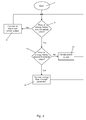
- Fig. 1 is a block diagram illustrating a wind turbine 1 being capable of performing a method according to an embodiment of the invention.
- the wind turbine 1 comprises a rotor 2 carrying a number of wind turbine blades 3, two of which are shown.
- the wind turbine blades 3 catch the wind, thereby causing the rotor 2 to rotate.
- the rotor 2 is connected to a generator 4, and the rotational movements of the rotor 2 cause the generator 4 to produce electrical energy.
- the electrical energy is then supplied to a power grid via a converter 5 and a transformer 6.
- the power grid is monitored in order to determine whether or not there is a match between a demand for energy defined by power consumers connected to the power grid and supply of energy to the power grid from power producers connected to the power grid, such as the wind turbine 1. If it is determined that there is a surplus of energy available in the power grid, and that the surplus of energy is sufficiently large, measures can be taken in order to remove, or at least reduce, this deficiency. A surplus of energy in the power grid can lead to instability of the power grid, and it is therefore very undesirable.
- the presence of a surplus of energy can, e.g., be detected by monitoring the price of energy of the power grid. For instance, if the price becomes negative, i.e. if the power producers have to pay the power grid in order to be allowed to provide produced power to the power grid, this is an indication that a large surplus of energy is available, and that there is a risk of the power grid becoming unstable.
- a reversing signal is generated for the wind turbine 1.
- the reversing signal may, e.g., be generated by the wind turbine 1 itself, by a control unit of the power grid, or by a wind farm controller of a wind farm which the wind turbine 1 forms part of.
- the wind turbine 1 In response to the reversing signal, the wind turbine 1 reverses the energy flow through the generator 4. Thereby the wind turbine 1 consumes power from the power grid instead of producing power and supplying it to the power grid. Due to the reversed energy flow through the generator 4, the generator 4 acts as a motor and drives a rotational movement of the rotor 2, including the wind turbine blades 3.
- Fig. 2 is a flow diagram illustrating a method for controlling operation of a wind turbine in accordance with an embodiment of the invention.
- the process is started at step 7.
- At step 8 it is investigated whether or not a price of energy of a power grid is below a first threshold value. This may be done by monitoring a power grid which the wind turbine is connected to, in particular by monitoring the price of energy.
- step 8 reveals that the price of energy is above the first threshold value, then it is determined that there is no need to adjust the power produced by the wind turbine and supplied to the power grid. Accordingly, the process is forwarded to step 9, where the wind turbine is operated at maximum power output. Then the process is returned to step 8 for continued monitoring of the power grid.
- step 8 reveals that the price of energy is below the first threshold value, this is an indication that there is a surplus of energy available in the power grid, and that there may be a risk of the power grid becoming unstable. Therefore the process is forwarded to step 10, where it is investigated whether or not the price of energy is below a second threshold value, which is lower than the first threshold value.
- step 10 reveals that the price of energy is above the second threshold value, i.e. that the price of energy is between the second threshold value and the first threshold value, then it is determined that it is necessary to adjust the supply of power to the power grid, but that there is no imminent risk of the power grid becoming unstable. Accordingly, the process is forwarded to step 11, where the power output of the wind turbine is derated, i.e. the wind turbine is operated in such a manner that the power output supplied to the power grid is lower than the maximum possible power output of the wind turbine under the given circumstances, including the current wind conditions.
- the supply of power to the power grid is reduced, and this may be sufficient to reduce the deficiency between the produced energy and the demand for energy, thereby increasing the price of energy, or at least to stop the decrease in the price of energy.
- the derating of the power output of the wind turbine may be sufficient to prevent that the deficiency between the production of energy and the demand for energy reaches a level which causes the power grid to become unstable.
- the price of energy is used as an indicator for or a measure of this deficiency. The process is then returned to step 8 for continued monitoring of the power grid.
- step 10 reveals that the price of energy is also below the second threshold value, then it is determined that the price of energy is critically low, i.e. the price of energy indicates that the deficiency between the produced energy and the demand for energy is critically high, and that there is an imminent risk that the power grid becomes unstable. Accordingly, the process is forwarded to step 12, where the energy flow through the generator is reversed. Thereby the wind turbine consumes energy from the power grid instead of supplying energy to the power grid. This will help in decreasing the deficiency between the produced energy and the demand for energy, thereby increasing the price of energy, and in stabilising the power grid. Finally, the process is returned to step 8 for continued monitoring of the power grid.
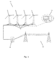
- Fig. 3 is a diagrammatic view of a wind farm 13 according to an embodiment of the invention.
- the wind farm 13 comprises a plurality of wind turbines 1 positioned within a site, and at least one of the wind turbines 1 of the wind farm 13 is capable of performing the method according to the invention.
- the wind farm 13 comprises a wind farm controller 14 arranged to control operation of the wind farm 13.
- the wind turbines 1 of the wind farm 13 are connected to a power grid 15 via a substation transformer 6.
- the wind turbines 1 are, thus, capable of producing power due to the wind, in the manner described above, and of supplying the produced power to the power grid 15.
- At least one of the wind turbines 1 of the wind farm 13 is capable of performing the method according to the invention, i.e. at least one of the wind turbines 1 is capable of reversing the energy flow through the generator of the wind turbine 1 in the case that there is a sufficiently large surplus of energy available in the power grid 15.
- the wind turbine(s) 1 consume(s) energy from the power grid 15 instead of supplying energy to the power grid 15, as described above.
Abstract
Description
- The present invention relates to a method for controlling a wind turbine. According to the invention an energy flow through the generator of the wind turbine is reversed when certain criteria are fulfilled. Thereby the wind turbine consumes energy from a power grid instead of producing energy to the power grid.
- Power grids have a number of power producers and a number of power consumers connected thereto. The power producers produce power and deliver the produced power to the power grid. Various kinds of power producers may be connected to a power grid, such as fossil fuelled power plants, nuclear power plants, wind turbines, e.g. in the form of individual wind turbines or wind farms, photovoltaic power cells, hydropower plants, etc.
- The larger conventional power producers, such as the fossil fuelled power plants and the nuclear power plants, provide a stable power production, which can be maintained constant on any desired time scale, but it may be difficult and often expensive to adjust the power production from these power producers, at least on a short time scale. Furthermore, the demand for energy defined by the power consumers connected to the power grid also changes, e.g. during the course of the day, during the course of the year, depending on outdoor temperature, etc.
- In order to keep the power grid stable, it is desirable to essentially maintain a match between power supplied to the power grid by the power producers and power consumed from the power grid by the power consumers. In situations of a high power production and a low power demand, there is a risk of the power grid becoming unstable.
-
EP 2 733 810 A1 - It is an object of embodiments of the invention to provide a method for controlling operation of a wind turbine which allows stabilisation of a power grid which the wind turbine is connected to.
- It is a further object of embodiments of the invention to provide a method for controlling operation of a wind turbine which allows the wind turbine to react fast on instabilities of a power grid which the wind turbine is connected to.
- According to a first aspect the invention provides a method for controlling operation of a wind turbine, the wind turbine comprising a rotor carrying one or more wind turbine blades, and a generator arranged to be coupled to a power grid, the method comprising the steps of:
- monitoring the power grid in order to determine whether or not there is a match between a demand for energy defined by power consumers connected to the power grid and supply of energy from power producers connected to the power grid,
- in the case that the supply of energy from power producers exceeds the demand for energy, and a deficiency between the demand for energy and the supply of energy exceeds a first threshold value, generating a reversing signal for the wind turbine, and
- reversing an energy flow through the generator upon receipt of the reversing signal, thereby causing the generator to consume power received from the power grid.
- The method according to the first aspect of the invention is a method for controlling operation of a wind turbine. The wind turbine comprises a rotor carrying one or more wind turbine blades, and a generator arranged to be coupled to a power grid. The wind turbine may further comprise a drive train, e.g. including a gear system, interconnecting the rotor and the generator. As an alternative, the wind turbine may be a gearless wind turbine, or a so-called direct drive wind turbine.
- During normal operation of the wind turbine the wind turbine blades catch the wind, thereby causing the rotor to rotate. The rotating movements of the rotor are transferred to the generator, possibly via a drive train. Thereby the generator produces electrical energy, which is supplied to the power grid.
- The power grid has a plurality of power producers and a plurality of power consumers connected thereto. The power producers, such as wind turbines, supply energy to the power grid, and the power consumers consume energy from the power grid. As described above, it is desirable that the energy supplied to the power grid by the power producers essentially matches the energy consumed by the power consumers, in order to stabilize the power grid.
- In the method according to the first aspect of the invention the power grid is monitored in order to determine whether or not there is a match between a demand for energy defined by power consumers connected to the power grid and supply of energy from power producers connected to the power grid.
- In the case that it turns out that the supply of energy from power producers exceeds the demand for energy then there is a surplus of energy available in the power grid, and therefore there is a risk that the power grid becomes unstable. It may therefore be necessary to take actions to prevent this. To this end the operators of the power grid may adjust the price of energy in a downwards direction in order to encourage the power consumers to consume more energy, and to encourage the power producers to produce less energy, thereby attempting to decrease the deficiency between the produced energy and the consumed energy. If this does not have the desired effect, the price of energy may continue to decrease, and may even become negative. In this case the power producers must pay the owner of the power grid for receiving the produced energy instead of receiving a revenue from the owner of the power grid.
- Thus, if the supply of energy from power producers exceeds the demand for energy, it is investigated how large the deficiency is in order to determine how severe the problem is. If the deficiency exceeds a first threshold value, it is determined that additional measures are required in order to prevent that the power grid becomes unstable. Therefore a reversing signal is generated for the wind turbine.
- Upon receipt of the reversing signal, the wind turbine reverses the energy flow through the generator, thereby causing the generator to consume power received from the power grid, instead of producing power and supplying it to the power grid. Thus, the generator operates as a motor. Accordingly, in this situation the wind turbine is transformed from a power producer to a power consumer, and it thereby efficiently helps in reducing the deficiency between produced energy and consumed energy. Furthermore, in the case that the energy price is negative, the owner of the wind turbine may even receive a revenue in this case.
- The step of monitoring the power grid comprises monitoring a price of energy supplied to the power grid by power producers, and the first threshold value may be defined by a negative price of energy supplied to the power grid. Accordingly, the energy flow through the generator is reversed when the price of energy becomes negative, or possibly when the price reaches a certain negative value. Thereby the owner of the wind turbine will receive payment from the owner of the power grid instead of having to pay the owner of the power grid for receiving produced energy. As described above, the price of energy may be reduced in the case of surplus energy being available in the power grid, and this may sometimes lead to a negative price of energy. Therefore the price of energy provides a measure for whether or not the energy supplied to the power grid by the power produces matches the energy demand of power consumers connected to the power grid.
- Thus, according to the first aspect of the invention, the wind turbine is capable of contributing to stabilising the power grid in the case of excess energy production, and the wind turbine is furthermore capable of reacting fast.
- As the share of produced energy originating from renewable power sources increases, the risk of instabilities of the power grid due to a mismatch between produced energy and consumed energy increases. It therefore becomes increasingly important to be able to take steps towards stabilising the power grid, and to be able to react fast. Therefore the method according to the first aspect of the invention makes it possible to allow a larger share of renewable energy sources to be connected to the power grid, thereby providing a more green energy production where the consumption of fossil fuel can be reduced.
- The reversed energy flow through the generator may result in the rotor being forced to rotate by the generator. According to this embodiment the generator, acting as a motor, drives the rotor, causing it to rotate, thereby producing mechanical energy. This is opposite to the situation during normal operation, where the wind drives the rotating movements of the rotor, and this rotating movement is transferred to the generator in order to generate electrical energy.
- In an embodiment, the step of monitoring the power grid may, e.g., further comprise monitoring voltage, frequency and/or any other suitable parameter which may indicate that there is a mismatch between the energy supplied to the power grid by the power producers and the demand for energy defined by the power consumers. For instance, in the case that the demand for energy decreases, while the energy production remains constant, the frequency of the power grid will increase. Therefore the frequency of the power grid is a suitable parameter for detecting a mismatch between the production of energy and the demand for energy.
- The method may further comprise the steps of:
- in the case that the supply of energy from power producers exceeds the demand for energy, and a deficiency between the demand for energy and the supply of energy exceeds a second threshold value, said second threshold value being lower than the first threshold value, generating a derating signal for the wind turbine, and
- decreasing the power output from the wind turbine to the power grid upon receipt of the derating signal.
- According to this embodiment, if the deficiency between the demand for energy and the supply of energy reaches a second threshold value, being lower than the first threshold value which results in the energy flow through the generator being reversed, the power output from the wind turbine is derated, i.e. the power produced by the wind turbine and supplied to the power grid is set to a level which is below the maximum possible power output of the wind turbine, under the given circumstances, including the current wind conditions.
- Thus, according to this embodiment, when the supply of energy to the power grid exceeds the demand for energy, and the deficiency between the produced energy and the demand for energy gradually increases, the second threshold value is first reached. When this happens, the power output from the wind turbine is derated in order to decrease the supply of produced energy to the power grid, thereby attempting to stop the increase in the deficiency between the produced energy and the demand for energy.
- However, if derating the power output from the wind turbine is not sufficient to balance the production of energy and the demand for energy, the deficiency will continue to increase. Thereby the first threshold value is reached, resulting in the energy flow through the generator being reversed, as described above.
- The power output from the wind turbine may be gradually decreased from a maximum level to zero as the deficiency between the produced energy and the demand for energy increases from the second threshold value to the first threshold value. Thereby a smooth transfer from maximum power output towards zero power production, and further towards reversing the energy flow through the generators is obtained.
- The method may further comprise the step of adjusting a pitch angle of the wind turbine blade(s) towards a braking position upon receipt of the reversing signal. When the pitch angle of the wind turbine blade(s) is adjusted towards a braking position, the wind turbine blade(s) counteract(s) the rotating movements of the rotor caused by the reversed energy flow through the generator. Thereby the energy consumption of the generator can be increased, and the wind turbine can to a greater extent contribute to stabilisation of the power grid.
- The wind turbine may form part of a wind farm comprising a plurality of wind turbines, and the wind farm may further comprise a wind farm controller arranged to control operation of the wind farm.
- In the present context the term 'wind farm' should be interpreted to mean a plurality of wind turbines arranged at a site. The wind turbines of a wind farm are often controlled in dependence of each other in order to maximise the energy production while minimising wear with respect to the entire wind farm instead of with respect to the individual wind turbine. This may be performed by means of a central wind farm controller.
- The step of generating a reversing signal may be performed by the wind farm controller. According to this embodiment, it is the wind farm controller which decides when the energy flow through the generator of a given wind turbine of the wind farm should be reversed. The wind farm controller may further decide which of the wind turbines of the wind farm should receive a reversing signal and which should not, if it is determined that reversing signals for one or more wind turbines are required in order to stabilise the power grid. In this case the wind turbines of the wind farm which do not receive a reversing signal may continue to operate normally, or they may be derated or even stopped.
- As an alternative, the step of generating a reversing signal may be performed by the wind turbine itself, or it may be performed by an external control unit, for instance a control unit forming part of the power grid system.
- Alternatively or additionally, the step of monitoring the power grid may be performed by the wind farm controller. According to this embodiment, the wind farm controller monitors the power grid, and thereby detects when a condition occurs which requires that one or more of the wind turbines of the wind farm reverses the energy flow through the generator. When this is detected, the wind farm controller may either generate reversing signals for one or more of the wind turbines of the wind farm, or the wind farm controller may alert all of the wind turbines of the wind farm, and based on this information, each of the wind turbines of the wind farm may determine whether or not to generate a reversing signal for itself.
- As an alternative, the step of monitoring the power grid may be performed by the wind turbine itself, or it may be performed by an external control unit, for instance a control unit forming part of the power grid.
- According to one embodiment, the reversing signal may be provided manually by an operator of the wind turbine, e.g. via a communication interface. In this case the operator may provide the reversing signal directly to a given turbine, or the operator may provide the reversing signal to a wind farm controller, which in turn distributes the reversing signal to appropriate wind turbines of the wind farm. Or the operator may provide reversing signals for selected wind turbines, based on a signal generated by the wind farm controller.
- The method may further comprise the steps of:
- selecting one or more wind turbines of the wind farm to receive a reversing signal in the case that the supply of energy from power producers exceeds the demand for energy, and a deficiency between the demand for energy and the supply of energy exceeds a first threshold value, and
- generating a reversing signal for each of the selected wind turbine(s).
- These steps may advantageously be performed by the wind farm controller. The wind turbine(s) to receive a reversing signal may, e.g., be selected in such a manner that the total energy production and/or energy consumption of the wind farm meet(s) specific requirements or overall goals. Alternatively or additionally, the wind turbine(s) may be selected in accordance with load considerations of the individual wind turbines and/or in such a manner that the selected wind turbines are not the same wind turbines which were selected the previous time reversing of the energy flow through the generator of one or more wind turbines was required.
- The reversing signal may be in the form of a power reference signal defining a negative power reference. Normally, a power reference signal is a signal which indicates a power level which the wind turbine must provide for the power grid. Sometimes the power grid may have a large capacity for receiving produced power. In this case the power reference signal to the wind turbine will normally corresponds to a maximum power output from the wind turbine under the given circumstances, including the current wind conditions. Sometimes the power grid may have limited capacity for receiving power. In this case the power reference signal to the wind turbine may correspond to a power output from the wind turbine, which is lower than the maximum possible power output, i.e. the wind turbine is derated, in order to limit the power supplied to the power grid. In the case that the capacity for receiving power of the power grid decreases, the power reference signal to the wind turbine may be correspondingly changed in order to gradually decrease the power output of the wind turbine. This may be continued until the power production of the wind turbine is zero, i.e. until the wind turbine is stopped. According to the method of the invention, the power reference signal may be even further decreased to a negative value, indicating that the wind turbine should consume power instead of producing power. Thus, according to this embodiment a smooth transfer from producing power to consuming power can be provided.
- According to a second aspect the invention provides a wind turbine comprising a rotor carrying one or more wind turbine blades, and a generator arranged to be coupled to a power grid, wherein the wind turbine is capable of carrying out the method according to the first aspect of the invention.
- It should be noted that a skilled person would readily recognise that any feature described in combination with the first aspect of the invention could also be combined with the second aspect of the invention, and vice versa. Thus, the remarks set forth above are equally applicable here.
- It is noted that the wind turbine may be capable of providing reactive power to the power grid. This capability is available, regardless of whether the wind turbine supplies energy to the power grid or consumes energy from the power grid.
- Furthermore, the invention provides a wind farm comprising a plurality of wind turbines and a wind farm controller arranged to control operation of the wind farm, wherein one or more of the wind turbines of the wind farm is a wind turbine according to the second aspect of the invention.
- The invention will now be described in further detail with reference to the accompanying drawings in which
-
Fig. 1 is a block diagram illustrating a wind turbine being capable of performing a method according to an embodiment of the invention, -
Fig. 2 is a flow diagram illustrating a method according to an embodiment of the invention, and -
Fig. 3 is a diagrammatic view of a wind farm according to an embodiment of the invention. -
Fig. 1 is a block diagram illustrating awind turbine 1 being capable of performing a method according to an embodiment of the invention. Thewind turbine 1 comprises arotor 2 carrying a number ofwind turbine blades 3, two of which are shown. - During normal operation, the
wind turbine blades 3 catch the wind, thereby causing therotor 2 to rotate. Therotor 2 is connected to agenerator 4, and the rotational movements of therotor 2 cause thegenerator 4 to produce electrical energy. The electrical energy is then supplied to a power grid via aconverter 5 and atransformer 6. - In a method according to the present invention, the power grid is monitored in order to determine whether or not there is a match between a demand for energy defined by power consumers connected to the power grid and supply of energy to the power grid from power producers connected to the power grid, such as the
wind turbine 1. If it is determined that there is a surplus of energy available in the power grid, and that the surplus of energy is sufficiently large, measures can be taken in order to remove, or at least reduce, this deficiency. A surplus of energy in the power grid can lead to instability of the power grid, and it is therefore very undesirable. - The presence of a surplus of energy can, e.g., be detected by monitoring the price of energy of the power grid. For instance, if the price becomes negative, i.e. if the power producers have to pay the power grid in order to be allowed to provide produced power to the power grid, this is an indication that a large surplus of energy is available, and that there is a risk of the power grid becoming unstable.
- Thus, when a sufficiently large surplus of energy in the power grid has been detected, a reversing signal is generated for the
wind turbine 1. The reversing signal may, e.g., be generated by thewind turbine 1 itself, by a control unit of the power grid, or by a wind farm controller of a wind farm which thewind turbine 1 forms part of. - In response to the reversing signal, the
wind turbine 1 reverses the energy flow through thegenerator 4. Thereby thewind turbine 1 consumes power from the power grid instead of producing power and supplying it to the power grid. Due to the reversed energy flow through thegenerator 4, thegenerator 4 acts as a motor and drives a rotational movement of therotor 2, including thewind turbine blades 3. -
Fig. 2 is a flow diagram illustrating a method for controlling operation of a wind turbine in accordance with an embodiment of the invention. The process is started atstep 7. Atstep 8 it is investigated whether or not a price of energy of a power grid is below a first threshold value. This may be done by monitoring a power grid which the wind turbine is connected to, in particular by monitoring the price of energy. - If
step 8 reveals that the price of energy is above the first threshold value, then it is determined that there is no need to adjust the power produced by the wind turbine and supplied to the power grid. Accordingly, the process is forwarded to step 9, where the wind turbine is operated at maximum power output. Then the process is returned to step 8 for continued monitoring of the power grid. - If
step 8 reveals that the price of energy is below the first threshold value, this is an indication that there is a surplus of energy available in the power grid, and that there may be a risk of the power grid becoming unstable. Therefore the process is forwarded to step 10, where it is investigated whether or not the price of energy is below a second threshold value, which is lower than the first threshold value. - If
step 10 reveals that the price of energy is above the second threshold value, i.e. that the price of energy is between the second threshold value and the first threshold value, then it is determined that it is necessary to adjust the supply of power to the power grid, but that there is no imminent risk of the power grid becoming unstable. Accordingly, the process is forwarded to step 11, where the power output of the wind turbine is derated, i.e. the wind turbine is operated in such a manner that the power output supplied to the power grid is lower than the maximum possible power output of the wind turbine under the given circumstances, including the current wind conditions. Thereby the supply of power to the power grid is reduced, and this may be sufficient to reduce the deficiency between the produced energy and the demand for energy, thereby increasing the price of energy, or at least to stop the decrease in the price of energy. Thus, the derating of the power output of the wind turbine may be sufficient to prevent that the deficiency between the production of energy and the demand for energy reaches a level which causes the power grid to become unstable. Furthermore, the price of energy is used as an indicator for or a measure of this deficiency. The process is then returned tostep 8 for continued monitoring of the power grid. - If
step 10 reveals that the price of energy is also below the second threshold value, then it is determined that the price of energy is critically low, i.e. the price of energy indicates that the deficiency between the produced energy and the demand for energy is critically high, and that there is an imminent risk that the power grid becomes unstable. Accordingly, the process is forwarded to step 12, where the energy flow through the generator is reversed. Thereby the wind turbine consumes energy from the power grid instead of supplying energy to the power grid. This will help in decreasing the deficiency between the produced energy and the demand for energy, thereby increasing the price of energy, and in stabilising the power grid. Finally, the process is returned to step 8 for continued monitoring of the power grid. -
Fig. 3 is a diagrammatic view of awind farm 13 according to an embodiment of the invention. Thewind farm 13 comprises a plurality ofwind turbines 1 positioned within a site, and at least one of thewind turbines 1 of thewind farm 13 is capable of performing the method according to the invention. - The
wind farm 13 comprises awind farm controller 14 arranged to control operation of thewind farm 13. Thewind turbines 1 of thewind farm 13 are connected to apower grid 15 via asubstation transformer 6. Thewind turbines 1 are, thus, capable of producing power due to the wind, in the manner described above, and of supplying the produced power to thepower grid 15. - Furthermore, at least one of the
wind turbines 1 of thewind farm 13 is capable of performing the method according to the invention, i.e. at least one of thewind turbines 1 is capable of reversing the energy flow through the generator of thewind turbine 1 in the case that there is a sufficiently large surplus of energy available in thepower grid 15. In this case the wind turbine(s) 1 consume(s) energy from thepower grid 15 instead of supplying energy to thepower grid 15, as described above.
Claims (11)
- A method for controlling operation of a wind turbine, the wind turbine comprising a rotor carrying one or more wind turbine blades, and a generator arranged to be coupled to a power grid, the method comprising the steps of:- monitoring the power grid in order to determine whether or not there is a match between a demand for energy defined by power consumers connected to the power grid and supply of energy from power producers connected to the power grid, the monitoring comprising monitoring a price of energy supplied to the power grid by power producers,- in the case that the supply of energy from power producers exceeds the demand for energy, and a deficiency between the demand for energy and the supply of energy exceeds a first threshold value, the first threshold value being defined by a negative price of energy supplied to the power grid, generating a reversing signal for the wind turbine, and- reversing an energy flow through the generator upon receipt of the reversing signal, thereby causing the generator to consume power received from the power grid.
- A method according to claim 1, wherein the reversed energy flow through the generator results in the rotor being forced to rotate by the generator.
- A method according to any of the preceding claims, further comprising the steps of:- in the case that the supply of energy from power producers exceeds the demand for energy, and a deficiency between the demand for energy and the supply of energy exceeds a second threshold value, said second threshold value being lower than the first threshold value, generating a derating signal for the wind turbine, and- decreasing the power output from the wind turbine to the power grid upon receipt of the derating signal.
- A method according to any of the preceding claims, further comprising the step of adjusting a pitch angle of the wind turbine blade(s) towards a braking position upon receipt of the reversing signal.
- A method according to any of the preceding claims, wherein the wind turbine forms part of a wind farm comprising a plurality of wind turbines, the wind farm further comprising a wind farm controller arranged to control operation of the wind farm.
- A method according to claim 5, wherein the step of generating a reversing signal is performed by the wind farm controller.
- A method according to claim 5 or 6, wherein the step of monitoring the power grid is performed by the wind farm controller.
- A method according to any of claims 5-7, further comprising the steps of:- selecting one or more wind turbines of the wind farm to receive a reversing signal in the case that the supply of energy from power producers exceeds the demand for energy, and a deficiency between the demand for energy and the supply of energy exceeds a first threshold value, and- generating a reversing signal for each of the selected wind turbine(s).
- A method according to any of the preceding claims, wherein the reversing signal is in the form of a power reference signal defining a negative power reference.
- A wind turbine comprising a rotor carrying one or more wind turbine blades, and a generator arranged to be coupled to a power grid, wherein the wind turbine is capable of carrying out the method according to any of claims 1-9.
- A wind farm comprising a plurality of wind turbines and a wind farm controller arranged to control operation of the wind farm, wherein one or more of the wind turbines of the wind farm is a wind turbine according to claim 10.
Applications Claiming Priority (1)
| Application Number | Priority Date | Filing Date | Title |
|---|---|---|---|
| DKPA201470413 | 2014-07-02 |
Publications (2)
| Publication Number | Publication Date |
|---|---|
| EP2963285A1 true EP2963285A1 (en) | 2016-01-06 |
| EP2963285B1 EP2963285B1 (en) | 2017-12-13 |
Family
ID=53539479
Family Applications (1)
| Application Number | Title | Priority Date | Filing Date |
|---|---|---|---|
| EP15173137.9A Active EP2963285B1 (en) | 2014-07-02 | 2015-06-22 | A method for controlling a wind turbine including reversing an energy flow through a generator |
Country Status (3)
| Country | Link |
|---|---|
| US (1) | US9500181B2 (en) |
| EP (1) | EP2963285B1 (en) |
| ES (1) | ES2656387T3 (en) |
Families Citing this family (1)
| Publication number | Priority date | Publication date | Assignee | Title |
|---|---|---|---|---|
| CN108561194B (en) * | 2018-04-27 | 2020-07-14 | 中国神华能源股份有限公司 | Primary frequency modulation control device and method for generator set |
Citations (5)
| Publication number | Priority date | Publication date | Assignee | Title |
|---|---|---|---|---|
| EP1775819A2 (en) * | 2005-10-15 | 2007-04-18 | NORDEX ENERGY GmbH | Method of operating a wind energy plant |
| EP2557311A1 (en) * | 2011-08-12 | 2013-02-13 | kk-electronic a/s | A method for controlling a wind power park and a wind power park controlled by such method |
| EP2733810A2 (en) | 2012-11-16 | 2014-05-21 | Siemens Aktiengesellschaft | Method of controlling a power network |
| WO2014194914A1 (en) * | 2013-06-03 | 2014-12-11 | Vestas Wind Systems A/S | Wind power plant controller |
| WO2015067408A1 (en) * | 2013-11-05 | 2015-05-14 | Wobben Properties Gmbh | Method for operating a wind turbine |
Family Cites Families (10)
| Publication number | Priority date | Publication date | Assignee | Title |
|---|---|---|---|---|
| US4449053A (en) * | 1981-07-27 | 1984-05-15 | Aluminum Company Of America | Vertical axis wind turbine |
| US4464579A (en) * | 1982-06-17 | 1984-08-07 | Control Data Corporation | Derrieus wind turbine electric generating system |
| US20020084655A1 (en) * | 2000-12-29 | 2002-07-04 | Abb Research Ltd. | System, method and computer program product for enhancing commercial value of electrical power produced from a renewable energy power production facility |
| US10135253B2 (en) * | 2000-12-29 | 2018-11-20 | Abb Schweiz Ag | System, method and computer program product for enhancing commercial value of electrical power produced from a renewable energy power production facility |
| US7030580B2 (en) * | 2003-12-22 | 2006-04-18 | Caterpillar Inc. | Motor/generator transient response system |
| GB2448138B (en) * | 2007-04-02 | 2009-07-08 | Quiet Revolution Ltd | Improvements in or relating to wind turbines |
| US8128361B2 (en) | 2008-12-19 | 2012-03-06 | Frontier Wind, Llc | Control modes for extendable rotor blades |
| EP2603695B1 (en) | 2010-08-12 | 2015-09-30 | Vestas Wind Systems A/S | Control of a wind power plant |
| CN203670098U (en) * | 2011-02-16 | 2014-06-25 | 株式会社安川电机 | Electric power conversion device for wind power generation, wind power generation device and wind field |
| WO2013000474A2 (en) | 2011-06-30 | 2013-01-03 | Vestas Wind Systems A/S | Energy arbitage using energy price forecast and wind power forecast |
-
2015
- 2015-06-22 EP EP15173137.9A patent/EP2963285B1/en active Active
- 2015-06-22 ES ES15173137.9T patent/ES2656387T3/en active Active
- 2015-06-30 US US14/755,103 patent/US9500181B2/en active Active
Patent Citations (5)
| Publication number | Priority date | Publication date | Assignee | Title |
|---|---|---|---|---|
| EP1775819A2 (en) * | 2005-10-15 | 2007-04-18 | NORDEX ENERGY GmbH | Method of operating a wind energy plant |
| EP2557311A1 (en) * | 2011-08-12 | 2013-02-13 | kk-electronic a/s | A method for controlling a wind power park and a wind power park controlled by such method |
| EP2733810A2 (en) | 2012-11-16 | 2014-05-21 | Siemens Aktiengesellschaft | Method of controlling a power network |
| WO2014194914A1 (en) * | 2013-06-03 | 2014-12-11 | Vestas Wind Systems A/S | Wind power plant controller |
| WO2015067408A1 (en) * | 2013-11-05 | 2015-05-14 | Wobben Properties Gmbh | Method for operating a wind turbine |
Also Published As
| Publication number | Publication date |
|---|---|
| US20160003221A1 (en) | 2016-01-07 |
| ES2656387T3 (en) | 2018-02-27 |
| US9500181B2 (en) | 2016-11-22 |
| EP2963285B1 (en) | 2017-12-13 |
Similar Documents
| Publication | Publication Date | Title |
|---|---|---|
| EP2307715B2 (en) | Power curtailment of wind turbines | |
| EP2227856B1 (en) | Apparatus and method for controlling the reactive power from a cluster of wind turbines connected to a utility grid | |
| US7908036B2 (en) | Power production control system and method | |
| US8227929B2 (en) | Multi-use energy storage for renewable sources | |
| EP2721291B1 (en) | Selective droop response control for a wind turbine power plant | |
| EP3149325B1 (en) | A wind power plant with reduced losses | |
| EP2847457B1 (en) | A power system and method for operating a wind power system with a dispatching algorithm | |
| JP4988540B2 (en) | Wind farm group, wind farm and control method thereof | |
| EP2824322B1 (en) | Output control device and output control method for windmill | |
| EP2904684A2 (en) | Line impedance compensation system | |
| EP3724487B1 (en) | Constant torque control of a wind turbine using an energy storage system | |
| US11525433B2 (en) | Power ramp rate control | |
| EP2963285B1 (en) | A method for controlling a wind turbine including reversing an energy flow through a generator | |
| US20220393477A1 (en) | Auxiliary power system control in hybrid power plants | |
| US10697432B2 (en) | Wind farm energy storage device for curtailment and auxiliary loads use | |
| WO2020125879A1 (en) | Levelling of fatigue levels of power generating units of a power plant comprising one or more wind turbine generators |
Legal Events
| Date | Code | Title | Description |
|---|---|---|---|
| PUAI | Public reference made under article 153(3) epc to a published international application that has entered the european phase |
Free format text: ORIGINAL CODE: 0009012 |
|
| AK | Designated contracting states |
Kind code of ref document: A1 Designated state(s): AL AT BE BG CH CY CZ DE DK EE ES FI FR GB GR HR HU IE IS IT LI LT LU LV MC MK MT NL NO PL PT RO RS SE SI SK SM TR |
|
| AX | Request for extension of the european patent |
Extension state: BA ME |
|
| 17P | Request for examination filed |
Effective date: 20160629 |
|
| RBV | Designated contracting states (corrected) |
Designated state(s): AL AT BE BG CH CY CZ DE DK EE ES FI FR GB GR HR HU IE IS IT LI LT LU LV MC MK MT NL NO PL PT RO RS SE SI SK SM TR |
|
| 17Q | First examination report despatched |
Effective date: 20161117 |
|
| GRAP | Despatch of communication of intention to grant a patent |
Free format text: ORIGINAL CODE: EPIDOSNIGR1 |
|
| RIC1 | Information provided on ipc code assigned before grant |
Ipc: F03D 7/04 20060101ALN20170825BHEP Ipc: F03D 7/02 20060101AFI20170825BHEP |
|
| INTG | Intention to grant announced |
Effective date: 20170925 |
|
| GRAS | Grant fee paid |
Free format text: ORIGINAL CODE: EPIDOSNIGR3 |
|
| GRAA | (expected) grant |
Free format text: ORIGINAL CODE: 0009210 |
|
| REG | Reference to a national code |
Ref country code: GB Ref legal event code: FG4D |
|
| REG | Reference to a national code |
Ref country code: AT Ref legal event code: REF Ref document number: 954646 Country of ref document: AT Kind code of ref document: T Effective date: 20171215 Ref country code: CH Ref legal event code: EP |
|
| REG | Reference to a national code |
Ref country code: IE Ref legal event code: FG4D |
|
| REG | Reference to a national code |
Ref country code: DE Ref legal event code: R096 Ref document number: 602015006578 Country of ref document: DE |
|
| REG | Reference to a national code |
Ref country code: ES Ref legal event code: FG2A Ref document number: 2656387 Country of ref document: ES Kind code of ref document: T3 Effective date: 20180227 |
|
| REG | Reference to a national code |
Ref country code: NL Ref legal event code: MP Effective date: 20171213 |
|
| PG25 | Lapsed in a contracting state [announced via postgrant information from national office to epo] |
Ref country code: SE Free format text: LAPSE BECAUSE OF FAILURE TO SUBMIT A TRANSLATION OF THE DESCRIPTION OR TO PAY THE FEE WITHIN THE PRESCRIBED TIME-LIMIT Effective date: 20171213 Ref country code: NO Free format text: LAPSE BECAUSE OF FAILURE TO SUBMIT A TRANSLATION OF THE DESCRIPTION OR TO PAY THE FEE WITHIN THE PRESCRIBED TIME-LIMIT Effective date: 20180313 Ref country code: FI Free format text: LAPSE BECAUSE OF FAILURE TO SUBMIT A TRANSLATION OF THE DESCRIPTION OR TO PAY THE FEE WITHIN THE PRESCRIBED TIME-LIMIT Effective date: 20171213 |
|
| REG | Reference to a national code |
Ref country code: AT Ref legal event code: MK05 Ref document number: 954646 Country of ref document: AT Kind code of ref document: T Effective date: 20171213 |
|
| PG25 | Lapsed in a contracting state [announced via postgrant information from national office to epo] |
Ref country code: RS Free format text: LAPSE BECAUSE OF FAILURE TO SUBMIT A TRANSLATION OF THE DESCRIPTION OR TO PAY THE FEE WITHIN THE PRESCRIBED TIME-LIMIT Effective date: 20171213 Ref country code: GR Free format text: LAPSE BECAUSE OF FAILURE TO SUBMIT A TRANSLATION OF THE DESCRIPTION OR TO PAY THE FEE WITHIN THE PRESCRIBED TIME-LIMIT Effective date: 20180314 Ref country code: LV Free format text: LAPSE BECAUSE OF FAILURE TO SUBMIT A TRANSLATION OF THE DESCRIPTION OR TO PAY THE FEE WITHIN THE PRESCRIBED TIME-LIMIT Effective date: 20171213 Ref country code: HR Free format text: LAPSE BECAUSE OF FAILURE TO SUBMIT A TRANSLATION OF THE DESCRIPTION OR TO PAY THE FEE WITHIN THE PRESCRIBED TIME-LIMIT Effective date: 20171213 Ref country code: BG Free format text: LAPSE BECAUSE OF FAILURE TO SUBMIT A TRANSLATION OF THE DESCRIPTION OR TO PAY THE FEE WITHIN THE PRESCRIBED TIME-LIMIT Effective date: 20180313 |
|
| REG | Reference to a national code |
Ref country code: FR Ref legal event code: PLFP Year of fee payment: 4 |
|
| PG25 | Lapsed in a contracting state [announced via postgrant information from national office to epo] |
Ref country code: NL Free format text: LAPSE BECAUSE OF FAILURE TO SUBMIT A TRANSLATION OF THE DESCRIPTION OR TO PAY THE FEE WITHIN THE PRESCRIBED TIME-LIMIT Effective date: 20171213 |
|
| PG25 | Lapsed in a contracting state [announced via postgrant information from national office to epo] |
Ref country code: CZ Free format text: LAPSE BECAUSE OF FAILURE TO SUBMIT A TRANSLATION OF THE DESCRIPTION OR TO PAY THE FEE WITHIN THE PRESCRIBED TIME-LIMIT Effective date: 20171213 Ref country code: SK Free format text: LAPSE BECAUSE OF FAILURE TO SUBMIT A TRANSLATION OF THE DESCRIPTION OR TO PAY THE FEE WITHIN THE PRESCRIBED TIME-LIMIT Effective date: 20171213 Ref country code: EE Free format text: LAPSE BECAUSE OF FAILURE TO SUBMIT A TRANSLATION OF THE DESCRIPTION OR TO PAY THE FEE WITHIN THE PRESCRIBED TIME-LIMIT Effective date: 20171213 Ref country code: CY Free format text: LAPSE BECAUSE OF FAILURE TO SUBMIT A TRANSLATION OF THE DESCRIPTION OR TO PAY THE FEE WITHIN THE PRESCRIBED TIME-LIMIT Effective date: 20171213 |
|
| PG25 | Lapsed in a contracting state [announced via postgrant information from national office to epo] |
Ref country code: IT Free format text: LAPSE BECAUSE OF FAILURE TO SUBMIT A TRANSLATION OF THE DESCRIPTION OR TO PAY THE FEE WITHIN THE PRESCRIBED TIME-LIMIT Effective date: 20171213 Ref country code: AT Free format text: LAPSE BECAUSE OF FAILURE TO SUBMIT A TRANSLATION OF THE DESCRIPTION OR TO PAY THE FEE WITHIN THE PRESCRIBED TIME-LIMIT Effective date: 20171213 Ref country code: PL Free format text: LAPSE BECAUSE OF FAILURE TO SUBMIT A TRANSLATION OF THE DESCRIPTION OR TO PAY THE FEE WITHIN THE PRESCRIBED TIME-LIMIT Effective date: 20171213 Ref country code: SM Free format text: LAPSE BECAUSE OF FAILURE TO SUBMIT A TRANSLATION OF THE DESCRIPTION OR TO PAY THE FEE WITHIN THE PRESCRIBED TIME-LIMIT Effective date: 20171213 Ref country code: IS Free format text: LAPSE BECAUSE OF FAILURE TO SUBMIT A TRANSLATION OF THE DESCRIPTION OR TO PAY THE FEE WITHIN THE PRESCRIBED TIME-LIMIT Effective date: 20180413 Ref country code: RO Free format text: LAPSE BECAUSE OF FAILURE TO SUBMIT A TRANSLATION OF THE DESCRIPTION OR TO PAY THE FEE WITHIN THE PRESCRIBED TIME-LIMIT Effective date: 20171213 |
|
| REG | Reference to a national code |
Ref country code: DE Ref legal event code: R097 Ref document number: 602015006578 Country of ref document: DE |
|
| PLBE | No opposition filed within time limit |
Free format text: ORIGINAL CODE: 0009261 |
|
| STAA | Information on the status of an ep patent application or granted ep patent |
Free format text: STATUS: NO OPPOSITION FILED WITHIN TIME LIMIT |
|
| 26N | No opposition filed |
Effective date: 20180914 |
|
| PG25 | Lapsed in a contracting state [announced via postgrant information from national office to epo] |
Ref country code: DK Free format text: LAPSE BECAUSE OF FAILURE TO SUBMIT A TRANSLATION OF THE DESCRIPTION OR TO PAY THE FEE WITHIN THE PRESCRIBED TIME-LIMIT Effective date: 20171213 |
|
| REG | Reference to a national code |
Ref country code: CH Ref legal event code: PL |
|
| PG25 | Lapsed in a contracting state [announced via postgrant information from national office to epo] |
Ref country code: SI Free format text: LAPSE BECAUSE OF FAILURE TO SUBMIT A TRANSLATION OF THE DESCRIPTION OR TO PAY THE FEE WITHIN THE PRESCRIBED TIME-LIMIT Effective date: 20171213 |
|
| REG | Reference to a national code |
Ref country code: BE Ref legal event code: MM Effective date: 20180630 |
|
| REG | Reference to a national code |
Ref country code: IE Ref legal event code: MM4A |
|
| PG25 | Lapsed in a contracting state [announced via postgrant information from national office to epo] |
Ref country code: LU Free format text: LAPSE BECAUSE OF NON-PAYMENT OF DUE FEES Effective date: 20180622 Ref country code: MC Free format text: LAPSE BECAUSE OF FAILURE TO SUBMIT A TRANSLATION OF THE DESCRIPTION OR TO PAY THE FEE WITHIN THE PRESCRIBED TIME-LIMIT Effective date: 20171213 |
|
| PG25 | Lapsed in a contracting state [announced via postgrant information from national office to epo] |
Ref country code: IE Free format text: LAPSE BECAUSE OF NON-PAYMENT OF DUE FEES Effective date: 20180622 Ref country code: CH Free format text: LAPSE BECAUSE OF NON-PAYMENT OF DUE FEES Effective date: 20180630 Ref country code: LI Free format text: LAPSE BECAUSE OF NON-PAYMENT OF DUE FEES Effective date: 20180630 |
|
| PG25 | Lapsed in a contracting state [announced via postgrant information from national office to epo] |
Ref country code: BE Free format text: LAPSE BECAUSE OF NON-PAYMENT OF DUE FEES Effective date: 20180630 |
|
| PG25 | Lapsed in a contracting state [announced via postgrant information from national office to epo] |
Ref country code: MT Free format text: LAPSE BECAUSE OF NON-PAYMENT OF DUE FEES Effective date: 20180622 |
|
| PG25 | Lapsed in a contracting state [announced via postgrant information from national office to epo] |
Ref country code: TR Free format text: LAPSE BECAUSE OF FAILURE TO SUBMIT A TRANSLATION OF THE DESCRIPTION OR TO PAY THE FEE WITHIN THE PRESCRIBED TIME-LIMIT Effective date: 20171213 |
|
| PG25 | Lapsed in a contracting state [announced via postgrant information from national office to epo] |
Ref country code: PT Free format text: LAPSE BECAUSE OF FAILURE TO SUBMIT A TRANSLATION OF THE DESCRIPTION OR TO PAY THE FEE WITHIN THE PRESCRIBED TIME-LIMIT Effective date: 20171213 |
|
| PG25 | Lapsed in a contracting state [announced via postgrant information from national office to epo] |
Ref country code: MK Free format text: LAPSE BECAUSE OF NON-PAYMENT OF DUE FEES Effective date: 20171213 Ref country code: LT Free format text: LAPSE BECAUSE OF FAILURE TO SUBMIT A TRANSLATION OF THE DESCRIPTION OR TO PAY THE FEE WITHIN THE PRESCRIBED TIME-LIMIT Effective date: 20171213 Ref country code: HU Free format text: LAPSE BECAUSE OF FAILURE TO SUBMIT A TRANSLATION OF THE DESCRIPTION OR TO PAY THE FEE WITHIN THE PRESCRIBED TIME-LIMIT; INVALID AB INITIO Effective date: 20150622 |
|
| PG25 | Lapsed in a contracting state [announced via postgrant information from national office to epo] |
Ref country code: AL Free format text: LAPSE BECAUSE OF FAILURE TO SUBMIT A TRANSLATION OF THE DESCRIPTION OR TO PAY THE FEE WITHIN THE PRESCRIBED TIME-LIMIT Effective date: 20171213 |
|
| P01 | Opt-out of the competence of the unified patent court (upc) registered |
Effective date: 20230521 |
|
| PGFP | Annual fee paid to national office [announced via postgrant information from national office to epo] |
Ref country code: FR Payment date: 20230622 Year of fee payment: 9 Ref country code: DE Payment date: 20230627 Year of fee payment: 9 |
|
| PGFP | Annual fee paid to national office [announced via postgrant information from national office to epo] |
Ref country code: GB Payment date: 20230620 Year of fee payment: 9 Ref country code: ES Payment date: 20230720 Year of fee payment: 9 |