EP2963247A1 - Cycle moteur double combiné avec au moins un moteur de cycle récupéré pour entraînement de rotor - Google Patents
Cycle moteur double combiné avec au moins un moteur de cycle récupéré pour entraînement de rotor Download PDFInfo
- Publication number
- EP2963247A1 EP2963247A1 EP15174825.8A EP15174825A EP2963247A1 EP 2963247 A1 EP2963247 A1 EP 2963247A1 EP 15174825 A EP15174825 A EP 15174825A EP 2963247 A1 EP2963247 A1 EP 2963247A1
- Authority
- EP
- European Patent Office
- Prior art keywords
- engine
- drive
- compressor
- air
- recuperative
- Prior art date
- Legal status (The legal status is an assumption and is not a legal conclusion. Google has not performed a legal analysis and makes no representation as to the accuracy of the status listed.)
- Granted
Links
- 238000002485 combustion reaction Methods 0.000 claims description 14
- 230000005611 electricity Effects 0.000 claims description 7
- 239000003570 air Substances 0.000 description 33
- 239000000047 product Substances 0.000 description 7
- 230000001172 regenerating effect Effects 0.000 description 3
- 239000000446 fuel Substances 0.000 description 2
- 239000012080 ambient air Substances 0.000 description 1
- 239000012530 fluid Substances 0.000 description 1
- 238000012986 modification Methods 0.000 description 1
- 230000004048 modification Effects 0.000 description 1
- 239000003507 refrigerant Substances 0.000 description 1
- 239000013589 supplement Substances 0.000 description 1
Images


Classifications
-
- B—PERFORMING OPERATIONS; TRANSPORTING
- B64—AIRCRAFT; AVIATION; COSMONAUTICS
- B64D—EQUIPMENT FOR FITTING IN OR TO AIRCRAFT; FLIGHT SUITS; PARACHUTES; ARRANGEMENT OR MOUNTING OF POWER PLANTS OR PROPULSION TRANSMISSIONS IN AIRCRAFT
- B64D35/00—Transmitting power from power plants to propellers or rotors; Arrangements of transmissions
- B64D35/08—Transmitting power from power plants to propellers or rotors; Arrangements of transmissions characterised by the transmission being driven by a plurality of power plants
-
- F—MECHANICAL ENGINEERING; LIGHTING; HEATING; WEAPONS; BLASTING
- F02—COMBUSTION ENGINES; HOT-GAS OR COMBUSTION-PRODUCT ENGINE PLANTS
- F02C—GAS-TURBINE PLANTS; AIR INTAKES FOR JET-PROPULSION PLANTS; CONTROLLING FUEL SUPPLY IN AIR-BREATHING JET-PROPULSION PLANTS
- F02C6/00—Plural gas-turbine plants; Combinations of gas-turbine plants with other apparatus; Adaptations of gas-turbine plants for special use
- F02C6/02—Plural gas-turbine plants having a common power output
-
- B—PERFORMING OPERATIONS; TRANSPORTING
- B64—AIRCRAFT; AVIATION; COSMONAUTICS
- B64C—AEROPLANES; HELICOPTERS
- B64C27/00—Rotorcraft; Rotors peculiar thereto
- B64C27/04—Helicopters
- B64C27/12—Rotor drives
- B64C27/14—Direct drive between power plant and rotor hub
-
- F—MECHANICAL ENGINEERING; LIGHTING; HEATING; WEAPONS; BLASTING
- F01—MACHINES OR ENGINES IN GENERAL; ENGINE PLANTS IN GENERAL; STEAM ENGINES
- F01D—NON-POSITIVE DISPLACEMENT MACHINES OR ENGINES, e.g. STEAM TURBINES
- F01D13/00—Combinations of two or more machines or engines
- F01D13/003—Combinations of two or more machines or engines with at least two independent shafts, i.e. cross-compound
-
- F—MECHANICAL ENGINEERING; LIGHTING; HEATING; WEAPONS; BLASTING
- F01—MACHINES OR ENGINES IN GENERAL; ENGINE PLANTS IN GENERAL; STEAM ENGINES
- F01D—NON-POSITIVE DISPLACEMENT MACHINES OR ENGINES, e.g. STEAM TURBINES
- F01D15/00—Adaptations of machines or engines for special use; Combinations of engines with devices driven thereby
- F01D15/12—Combinations with mechanical gearing
-
- F—MECHANICAL ENGINEERING; LIGHTING; HEATING; WEAPONS; BLASTING
- F02—COMBUSTION ENGINES; HOT-GAS OR COMBUSTION-PRODUCT ENGINE PLANTS
- F02C—GAS-TURBINE PLANTS; AIR INTAKES FOR JET-PROPULSION PLANTS; CONTROLLING FUEL SUPPLY IN AIR-BREATHING JET-PROPULSION PLANTS
- F02C3/00—Gas-turbine plants characterised by the use of combustion products as the working fluid
- F02C3/14—Gas-turbine plants characterised by the use of combustion products as the working fluid characterised by the arrangement of the combustion chamber in the plant
- F02C3/145—Gas-turbine plants characterised by the use of combustion products as the working fluid characterised by the arrangement of the combustion chamber in the plant the combustion chamber being in the reverse flow-type
-
- F—MECHANICAL ENGINEERING; LIGHTING; HEATING; WEAPONS; BLASTING
- F02—COMBUSTION ENGINES; HOT-GAS OR COMBUSTION-PRODUCT ENGINE PLANTS
- F02C—GAS-TURBINE PLANTS; AIR INTAKES FOR JET-PROPULSION PLANTS; CONTROLLING FUEL SUPPLY IN AIR-BREATHING JET-PROPULSION PLANTS
- F02C6/00—Plural gas-turbine plants; Combinations of gas-turbine plants with other apparatus; Adaptations of gas-turbine plants for special use
- F02C6/18—Plural gas-turbine plants; Combinations of gas-turbine plants with other apparatus; Adaptations of gas-turbine plants for special use using the waste heat of gas-turbine plants outside the plants themselves, e.g. gas-turbine power heat plants
-
- F—MECHANICAL ENGINEERING; LIGHTING; HEATING; WEAPONS; BLASTING
- F02—COMBUSTION ENGINES; HOT-GAS OR COMBUSTION-PRODUCT ENGINE PLANTS
- F02C—GAS-TURBINE PLANTS; AIR INTAKES FOR JET-PROPULSION PLANTS; CONTROLLING FUEL SUPPLY IN AIR-BREATHING JET-PROPULSION PLANTS
- F02C7/00—Features, components parts, details or accessories, not provided for in, or of interest apart form groups F02C1/00 - F02C6/00; Air intakes for jet-propulsion plants
- F02C7/08—Heating air supply before combustion, e.g. by exhaust gases
- F02C7/10—Heating air supply before combustion, e.g. by exhaust gases by means of regenerative heat-exchangers
-
- F—MECHANICAL ENGINEERING; LIGHTING; HEATING; WEAPONS; BLASTING
- F02—COMBUSTION ENGINES; HOT-GAS OR COMBUSTION-PRODUCT ENGINE PLANTS
- F02C—GAS-TURBINE PLANTS; AIR INTAKES FOR JET-PROPULSION PLANTS; CONTROLLING FUEL SUPPLY IN AIR-BREATHING JET-PROPULSION PLANTS
- F02C7/00—Features, components parts, details or accessories, not provided for in, or of interest apart form groups F02C1/00 - F02C6/00; Air intakes for jet-propulsion plants
- F02C7/32—Arrangement, mounting, or driving, of auxiliaries
-
- F—MECHANICAL ENGINEERING; LIGHTING; HEATING; WEAPONS; BLASTING
- F02—COMBUSTION ENGINES; HOT-GAS OR COMBUSTION-PRODUCT ENGINE PLANTS
- F02C—GAS-TURBINE PLANTS; AIR INTAKES FOR JET-PROPULSION PLANTS; CONTROLLING FUEL SUPPLY IN AIR-BREATHING JET-PROPULSION PLANTS
- F02C7/00—Features, components parts, details or accessories, not provided for in, or of interest apart form groups F02C1/00 - F02C6/00; Air intakes for jet-propulsion plants
- F02C7/36—Power transmission arrangements between the different shafts of the gas turbine plant, or between the gas-turbine plant and the power user
-
- F—MECHANICAL ENGINEERING; LIGHTING; HEATING; WEAPONS; BLASTING
- F05—INDEXING SCHEMES RELATING TO ENGINES OR PUMPS IN VARIOUS SUBCLASSES OF CLASSES F01-F04
- F05D—INDEXING SCHEME FOR ASPECTS RELATING TO NON-POSITIVE-DISPLACEMENT MACHINES OR ENGINES, GAS-TURBINES OR JET-PROPULSION PLANTS
- F05D2220/00—Application
- F05D2220/30—Application in turbines
- F05D2220/32—Application in turbines in gas turbines
- F05D2220/329—Application in turbines in gas turbines in helicopters
-
- F—MECHANICAL ENGINEERING; LIGHTING; HEATING; WEAPONS; BLASTING
- F05—INDEXING SCHEMES RELATING TO ENGINES OR PUMPS IN VARIOUS SUBCLASSES OF CLASSES F01-F04
- F05D—INDEXING SCHEME FOR ASPECTS RELATING TO NON-POSITIVE-DISPLACEMENT MACHINES OR ENGINES, GAS-TURBINES OR JET-PROPULSION PLANTS
- F05D2260/00—Function
- F05D2260/40—Transmission of power
- F05D2260/403—Transmission of power through the shape of the drive components
- F05D2260/4031—Transmission of power through the shape of the drive components as in toothed gearing
- F05D2260/40311—Transmission of power through the shape of the drive components as in toothed gearing of the epicyclical, planetary or differential type
-
- F—MECHANICAL ENGINEERING; LIGHTING; HEATING; WEAPONS; BLASTING
- F05—INDEXING SCHEMES RELATING TO ENGINES OR PUMPS IN VARIOUS SUBCLASSES OF CLASSES F01-F04
- F05D—INDEXING SCHEME FOR ASPECTS RELATING TO NON-POSITIVE-DISPLACEMENT MACHINES OR ENGINES, GAS-TURBINES OR JET-PROPULSION PLANTS
- F05D2260/00—Function
- F05D2260/50—Kinematic linkage, i.e. transmission of position
- F05D2260/53—Kinematic linkage, i.e. transmission of position using gears
- F05D2260/532—Kinematic linkage, i.e. transmission of position using gears of the bevelled or angled type
Definitions
- This application relates to a combination of two distinct engine types which can be efficiently utilized to drive a rotor.
- Gas turbine engines are known and are used to drive a variety of aircraft.
- One known type of gas turbine engine is a so-called recuperated cycle engine. In such an engine, heat is captured and used to heat air downstream of a compressor prior to being delivered into a combustion section.
- Another type of gas turbine engine is a simple cycle engine wherein such preheating does not occur.
- Gas turbine engines have been utilized to drive rotary wing aircraft, such as a propeller system for a helicopter. Typically, a pair of engines are placed on the helicopter. Under certain conditions, drive from both of the engines is required. However, under many standard operating conditions, only one of the engines is sufficient to provide adequate power.
- Pilots for such a rotary wing aircraft will often drive both engines as a safety measure.
- a drive architecture comprises a rotor and a gearbox for driving the rotor.
- a pair of input gears provides rotational drive to the gearbox.
- a first recuperative cycle engine drives one of the pair of gears and a second engine drives the other of the pair of gears.
- the first recuperative cycle engine and the second engine are both gas turbine engines.
- a power takeoff from a drive shaft of the second engine supplies rotational drive to drive at least one component in the first recuperative cycle drive.
- the power takeoff from the second engine serves to provide rotational input to drive a compressor in the first recuperative cycle engine.
- air downstream of the compressor in the first recuperative cycle engine is directed through a heat exchanger downstream of a turbine section in the first recuperative cycle engine.
- the air is heated and is then returned into a combustor section, which is intermediate the compressor and the turbine section in the first recuperative cycle engine.
- air is tapped from the second engine downstream of a compressor in the second engine and passed into a second heat exchanger where it additionally provides heat to the air from the compressor in the first recuperative cycle engine before the air in the first recuperative cycle engine is returned to the combustion section.
- the air from the second engine is passed from a location downstream of a single compressor rotor and through the second heat exchanger.
- a bypass feature is provided on the tap from the second engine into the second heat exchanger with the bypass being provided with valving to selectively deliver air from the second engine to the second heat exchanger or bypass air back to the second engine.
- the drive shaft for the recuperative cycle engine also rotates a thrust propeller.
- the second engine is a reverse core engine wherein air is delivered along a path past a turbine section in the second engine, past a compressor in the second engine, and then turned into the compressor for the second engine.
- air downstream of the turbine section in the first recuperative cycle engine passes through a thrust nozzle.
- the thrust nozzle is a variable area nozzle.
- the power takeoff drives a generator to generate electricity.
- the generator provides power to a power electronic system which, in turn, drives the mechanical connection.
- a mechanical connection and a generator communicate with the power connection and with a shaft for the compressor in the second engine.
- the mechanical connection provides power to the shaft for the compressor and the second engine.
- the mechanical connection receives the rotary drive from the shaft of the compressor of the second engine.
- a rotary wing aircraft drive 20 such as a propeller system for a helicopter, is illustrated in Figure 1 .
- a main rotor gearbox 22 drives the propeller system 20.
- a pair of input drive gears 26 and 30 are shown schematically driving the gearbox 22.
- Gear 26 is driven by a shaft 24 on an engine 18.
- Gear 30 is driven by a shaft 28 which is part of an engine 19.
- Engine 19 is a "reverse core” engine.
- an inlet duct 52 delivers air to a turning end 56, where it is then delivered into a compressor 54.
- the air is compressed in compressor 54, delivered into a combustion section 58, mixed with fuel and ignited.
- Products of this combustion pass downstream over a turbine rotor 60, which drives the compressor rotor 54. Downstream of the turbine rotor 60, the products of combustion drive another turbine rotor 34 which drives the shaft 28. Downstream of the turbine rotor 34, the products of combustion are reversed through an exit duct 35.
- the engine 18 has an inlet duct 17 delivering air into a compressor 32.
- Compressor 32 delivers air into a combustion section 42, where it is mixed with fuel and ignited. Products of this combustion drive a turbine rotor 44, which, in turn, drives a shaft 46 to drive the compressor rotor 32.
- Engine 18 is a recuperative engine, while engine 19 is a simple cycle engine.
- a simple cycle engine has one instance of heat input without work being added or subtracted.
- the heat input typically is a combustor.
- a recuperative, or regenerative cycle recycles a fraction of the heat input by the combustor by transferring heat from the gas flow of products of combustion exiting the turbine to the air flow that exits the compressor and enters the combustor.
- the heat transfer device typically is a heat exchanger.
- the temperature of the air flow exiting the compressor is lower than the temperature of the gas flow exiting the turbine; hence, heat can be transferred from the gas flow to the air flow. This reduces the heat input required of the combustor.
- the temperature of the air flow exiting the compressor is higher than the temperature of the gas flow exiting the turbine; hence, heat cannot be transferred from the gas flow to the air flow of the simple cycle engine.
- heat can be transferred from the air flow of the simple cycle engine to the air flow of the regenerative cycle engine. Transferring heat from the air flow of the simple cycle engine intercools the air flow of the compressor of the simple cycle engine, lowering the compressor exit temperature of the airflow of the simple cycle. Controlling compressor exit temperature is advantageous when the ambient air inlet temperature of the compressor is high.
- the combination synergistically controls the inlet temperature of the combustor for each engine.
- air downstream of the compressor rotor 32 passes through a heat exchanger 40, where it is heated by the products of combustion downstream of the turbine rotor 35.
- the air may also pass to a heat exchanger 50 where it is heated by air from tap 62, which has been heated in the compressor 54.
- a gear 76 rotates with the compressor 32 and receives drive from a bevel gear 74.
- Bevel gear 74 is driven by a gear 70, driven by the shaft 28.
- the engine 19 supplements power to engine 18 through the gear 74.
- the gear and shaft combination 72/74 drive the gear 76 and supply power to the compressor 32. This saves power that the turbine 44 would otherwise have to deliver to the compressor 32 and results in higher temperatures preheating the air in the heat exchanger 40. As such, this cycle operates more efficiently.
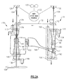
- Figures 2A and B show an engine system, wherein features generally identical to those of Figure 1 are simply identified by a number moved 100 higher.
- a portion 15 of the refrigerant downstream of the compressor stage 182 is tapped as the intercooler 184, and is returned at 13 downstream of the compressor stage 180.
- a portion of the air compressed at stage 182 does pass the stage 180, and is then mixed with the returning fluid 13.
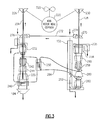
- Figure 3 shows an engine wherein features identical to Figures 2A /B are identified by the number 200 added to the reference arrows in Figures 2A /B.
- the thrust propeller has been replaced by a thrusting nozzle 184, which may be a variable nozzle, as is otherwise known.
- FIG. 4 shows the heat exchanger 350 and a feature which may be placed on the line 384 leading from the compressor section through the heat exchanger 350.
- a shutoff valve 385 may be controlled in combination with the valve 386 to divert air through a line 387, when it is not desired to achieve the intercooling.
- An appropriate control 388 controls the valves 385 and 386 and a worker of ordinary skill in the art would understand when to provide such control.
- Figure 5 shows an embodiment wherein the connection between the engine is utilized to generate electrical power.
- the gear 374 drives a shaft 372 which, in turn, drives a generator 375.
- Generator 375 powers a power electronics 377 which can provide electrical power to a use 376.
- the power electronics 377 drives a combined motor and mechanical connection 379 that passes rotational power to a shaft 380, such that it can supply drive to the recuperative engine, as in the prior embodiments.
- Figure 6 shows an embodiment, wherein the input gears 600 drives a shaft 602 to, in turn, drive a generator 679.
- Generator 679 supplies power to the power electronics 677.
- Motor and mechanical connection 680 receives power from the power electronics 677 to drive shaft 602.
- the combination of 680/679 also is known in the art as a motor/generator.
- Another generator 681 Downstream of the power electronics, another generator 681 generates electricity and supplies it back to the power electronics 677 and also drives a combined motor and mechanical connection 682, which drives the shaft portion 683 to supply mechanical energy to the recuperative engine 618.
- Another generator 681 generates electricity and supplies it back to the power electronics 677 and also drives the motor 682, which drives the shaft portion 683 to supply mechanical energy to the recuperative engine 618.
- a use 676 for generated electrical power is disclosed schematically. Mechanical power from engine 618 is converted to electrical power that is converted back to mechanical power to drive gear 600 that drivers gear 670 and shaft 628 of engine 619.
- the combination of 682/681 also is known in the art as a motor/generator.
- FIG 7A shows an embodiment which may be incorporated into the embodiments of Figures 5 or 6 .
- a generator 706 receives power from the line 700 which may be the power electronics in the Figures 5 or 6 embodiment. It drives the mechanical connection 708 to supply power to a shaft 702, which drives a compressor 704.
- Figure 7B shows another embodiment wherein the compressors 808 and 810 rotate with a shaft 806 to, in turn, drive a mechanical connection 804 to generate electricity at generator 802 and supply that generator electricity though a line 800 back to the power electronics as in the Figures 5 or 6 embodiments.
- While a propeller system for a rotary wing aircraft is specifically disclosed, other gearbox applications for driving a rotor may benefit from these teachings.
- certain aircraft are provided with a lift fan, and a rotor for such a fan may well benefit from the drive architecture of this disclosure.
Landscapes
- Engineering & Computer Science (AREA)
- Mechanical Engineering (AREA)
- Chemical & Material Sciences (AREA)
- Combustion & Propulsion (AREA)
- General Engineering & Computer Science (AREA)
- Aviation & Aerospace Engineering (AREA)
- Structures Of Non-Positive Displacement Pumps (AREA)
- Control Of Turbines (AREA)
Applications Claiming Priority (1)
| Application Number | Priority Date | Filing Date | Title |
|---|---|---|---|
| US201462019478P | 2014-07-01 | 2014-07-01 |
Publications (2)
| Publication Number | Publication Date |
|---|---|
| EP2963247A1 true EP2963247A1 (fr) | 2016-01-06 |
| EP2963247B1 EP2963247B1 (fr) | 2019-06-19 |
Family
ID=54007459
Family Applications (1)
| Application Number | Title | Priority Date | Filing Date |
|---|---|---|---|
| EP15174825.8A Active EP2963247B1 (fr) | 2014-07-01 | 2015-07-01 | Cycle moteur double combiné avec au moins un moteur de cycle récupéré pour entraînement de rotor |
Country Status (2)
| Country | Link |
|---|---|
| US (2) | US10066547B2 (fr) |
| EP (1) | EP2963247B1 (fr) |
Cited By (3)
| Publication number | Priority date | Publication date | Assignee | Title |
|---|---|---|---|---|
| WO2018234684A1 (fr) * | 2017-06-22 | 2018-12-27 | Safran | Agencement de deux turbomoteurs |
| EP3350076A4 (fr) * | 2015-09-15 | 2019-05-08 | Sikorsky Aircraft Corporation | Agencement de système d'entraînement pour giravion |
| EP4124574A1 (fr) * | 2021-07-30 | 2023-02-01 | Pratt & Whitney Canada Corp. | Système multi-moteur et transfert de puissance entre les moteurs de celui-ci |
Families Citing this family (13)
| Publication number | Priority date | Publication date | Assignee | Title |
|---|---|---|---|---|
| US9726112B2 (en) * | 2013-03-07 | 2017-08-08 | United Technologies Corporation | Reverse flow gas turbine engine airflow bypass |
| US10066547B2 (en) * | 2014-07-01 | 2018-09-04 | United Technologies Corporation | Combined two engine cycle with at least one recuperated cycle engine for rotor drive |
| US20180327109A1 (en) * | 2015-11-16 | 2018-11-15 | Safran Aircraft Engines | Propulsion unit comprising a main engine and an auxiliary engine |
| US9432929B1 (en) * | 2015-12-08 | 2016-08-30 | Uber Technologies, Inc. | Communication configuration system for a fleet of automated vehicles |
| DE102016204018A1 (de) * | 2016-03-11 | 2017-09-14 | Robert Bosch Gmbh | Verfahren und Vorrichtung zur Bestimmung der Querneigung einer Fahrbahn |
| US10760484B2 (en) * | 2016-09-16 | 2020-09-01 | Pratt & Whitney Canada Corp. | Multi-engine aircraft power plant with heat recuperation |
| FR3082225B1 (fr) | 2018-06-07 | 2020-06-05 | Safran Helicopter Engines | Systeme propulsif asymetrique a recuperation de chaleur |
| US11274599B2 (en) | 2019-03-27 | 2022-03-15 | Pratt & Whitney Canada Corp. | Air system switching system to allow aero-engines to operate in standby mode |
| US11391219B2 (en) | 2019-04-18 | 2022-07-19 | Pratt & Whitney Canada Corp. | Health monitor for air switching system |
| US11859563B2 (en) | 2019-05-31 | 2024-01-02 | Pratt & Whitney Canada Corp. | Air system of multi-engine aircraft |
| US11274611B2 (en) | 2019-05-31 | 2022-03-15 | Pratt & Whitney Canada Corp. | Control logic for gas turbine engine fuel economy |
| US11326525B2 (en) * | 2019-10-11 | 2022-05-10 | Pratt & Whitney Canada Corp. | Aircraft bleed air systems and methods |
| US20230356831A1 (en) * | 2020-08-21 | 2023-11-09 | Hill Group Technologies Limited | An improved rotorcraft |
Citations (5)
| Publication number | Priority date | Publication date | Assignee | Title |
|---|---|---|---|---|
| GB1026458A (en) * | 1964-03-23 | 1966-04-20 | Bristol Siddeley Engines Ltd | Aircraft power plant |
| EP0272822A1 (fr) * | 1986-12-03 | 1988-06-29 | Short Brothers Plc | Propulsion pour aéronef |
| EP2052967A1 (fr) * | 2007-10-26 | 2009-04-29 | Eurocopter | Amélioration aux giravions équipés de turbomoteurs |
| EP2602458A2 (fr) * | 2011-12-06 | 2013-06-12 | Pratt & Whitney Canada Corp. | Procédé de contrôle pour multiples turbomoteurs et système pour hélicoptères |
| FR2992024A1 (fr) * | 2012-06-15 | 2013-12-20 | Turbomeca | Procede et architecture de transfert d'energie optimise entre un moteur auxiliaire de puissance et les moteurs principaux d'un helicoptere |
Family Cites Families (7)
| Publication number | Priority date | Publication date | Assignee | Title |
|---|---|---|---|---|
| GB2316048B (en) * | 1989-10-11 | 1998-06-24 | Rolls Royce Plc | Improvements in or relating to Vstovl engines |
| US5873546A (en) | 1997-06-19 | 1999-02-23 | Sikorsky Aircraft Corporation | System and method for conducting one engine inoperative flight procedures training in a dual-engine helicopter |
| US6193189B1 (en) | 1999-08-10 | 2001-02-27 | James R. Keever | Rotary engine and helicopter application |
| FR2827636B1 (fr) | 2001-07-19 | 2003-11-28 | Eurocopter France | Systeme de regulation du regime d'un moteur d'un helicoptere |
| FR2858999B1 (fr) * | 2003-08-18 | 2005-11-11 | Snecma Moteurs | Turbomachine pour aeronef a emissions de bruit reduites |
| FR2962488B1 (fr) * | 2010-07-06 | 2014-05-02 | Turbomeca | Procede et architecture de recombinaison de puissance de turbomachine |
| US10066547B2 (en) * | 2014-07-01 | 2018-09-04 | United Technologies Corporation | Combined two engine cycle with at least one recuperated cycle engine for rotor drive |
-
2015
- 2015-06-12 US US14/737,633 patent/US10066547B2/en active Active
- 2015-07-01 EP EP15174825.8A patent/EP2963247B1/fr active Active
-
2018
- 2018-07-10 US US16/030,893 patent/US10669933B2/en active Active
Patent Citations (5)
| Publication number | Priority date | Publication date | Assignee | Title |
|---|---|---|---|---|
| GB1026458A (en) * | 1964-03-23 | 1966-04-20 | Bristol Siddeley Engines Ltd | Aircraft power plant |
| EP0272822A1 (fr) * | 1986-12-03 | 1988-06-29 | Short Brothers Plc | Propulsion pour aéronef |
| EP2052967A1 (fr) * | 2007-10-26 | 2009-04-29 | Eurocopter | Amélioration aux giravions équipés de turbomoteurs |
| EP2602458A2 (fr) * | 2011-12-06 | 2013-06-12 | Pratt & Whitney Canada Corp. | Procédé de contrôle pour multiples turbomoteurs et système pour hélicoptères |
| FR2992024A1 (fr) * | 2012-06-15 | 2013-12-20 | Turbomeca | Procede et architecture de transfert d'energie optimise entre un moteur auxiliaire de puissance et les moteurs principaux d'un helicoptere |
Cited By (8)
| Publication number | Priority date | Publication date | Assignee | Title |
|---|---|---|---|---|
| EP3350076A4 (fr) * | 2015-09-15 | 2019-05-08 | Sikorsky Aircraft Corporation | Agencement de système d'entraînement pour giravion |
| US11148822B2 (en) | 2015-09-15 | 2021-10-19 | Sikorsky Aircraft Corporation | Drive system arrangement for rotorcraft |
| WO2018234684A1 (fr) * | 2017-06-22 | 2018-12-27 | Safran | Agencement de deux turbomoteurs |
| FR3068077A1 (fr) * | 2017-06-22 | 2018-12-28 | Safran | Agencement de deux turbomoteurs |
| CN110799741A (zh) * | 2017-06-22 | 2020-02-14 | 赛峰集团 | 两个涡轮轴发动机的布置 |
| US11300048B2 (en) | 2017-06-22 | 2022-04-12 | Safran | Arrangement of two turboshaft engines |
| EP4124574A1 (fr) * | 2021-07-30 | 2023-02-01 | Pratt & Whitney Canada Corp. | Système multi-moteur et transfert de puissance entre les moteurs de celui-ci |
| US11905888B2 (en) | 2021-07-30 | 2024-02-20 | Pratt & Whitney Canada Corp. | Multi-engine system and power transfer between engines thereof |
Also Published As
| Publication number | Publication date |
|---|---|
| US10066547B2 (en) | 2018-09-04 |
| EP2963247B1 (fr) | 2019-06-19 |
| US10669933B2 (en) | 2020-06-02 |
| US20160003144A1 (en) | 2016-01-07 |
| US20180320591A1 (en) | 2018-11-08 |
Similar Documents
| Publication | Publication Date | Title |
|---|---|---|
| US10669933B2 (en) | Combined two engine cycle with at least one recuperated cycle engine for rotor drive | |
| EP3127812B1 (fr) | Système pneumatique d'avion | |
| US9878796B2 (en) | Hybrid drive for gas turbine engine | |
| US20190162118A1 (en) | Gas turbine engine with plural accessory air paths | |
| EP2452878B1 (fr) | Système de propulsion pour avion et procédé d'opération d'un tel système | |
| US9021780B2 (en) | Energy extraction and transfer system for a gas turbine engine | |
| US9328667B2 (en) | Systems and methods for changing a speed of a compressor boost stage in a gas turbine | |
| EP2452876B1 (fr) | Système de propulsion d'avion et système pour faire rouler un avion | |
| US10662960B2 (en) | Supply of air to an air-conditioning circuit of an aircraft cabin | |
| EP2128404A2 (fr) | Entraînement de machines auxiliaires de turbine à gaz avec embrayage de pontage | |
| US10605107B2 (en) | Tip clearance control system | |
| US20150337738A1 (en) | Two Spool Gas Generator with Improved Air Porting | |
| US10472071B2 (en) | Hybrid compressor bleed air for aircraft use | |
| US20210079848A1 (en) | Secondary fuel flow demand fuel pumping system | |
| EP2924247B1 (fr) | Entraînement hybride pour moteur à turbine à gaz |
Legal Events
| Date | Code | Title | Description |
|---|---|---|---|
| PUAI | Public reference made under article 153(3) epc to a published international application that has entered the european phase |
Free format text: ORIGINAL CODE: 0009012 |
|
| AK | Designated contracting states |
Kind code of ref document: A1 Designated state(s): AL AT BE BG CH CY CZ DE DK EE ES FI FR GB GR HR HU IE IS IT LI LT LU LV MC MK MT NL NO PL PT RO RS SE SI SK SM TR |
|
| AX | Request for extension of the european patent |
Extension state: BA ME |
|
| 17P | Request for examination filed |
Effective date: 20160706 |
|
| RBV | Designated contracting states (corrected) |
Designated state(s): AL AT BE BG CH CY CZ DE DK EE ES FI FR GB GR HR HU IE IS IT LI LT LU LV MC MK MT NL NO PL PT RO RS SE SI SK SM TR |
|
| RAP1 | Party data changed (applicant data changed or rights of an application transferred) |
Owner name: UNITED TECHNOLOGIES CORPORATION |
|
| GRAP | Despatch of communication of intention to grant a patent |
Free format text: ORIGINAL CODE: EPIDOSNIGR1 |
|
| STAA | Information on the status of an ep patent application or granted ep patent |
Free format text: STATUS: GRANT OF PATENT IS INTENDED |
|
| RIC1 | Information provided on ipc code assigned before grant |
Ipc: B64C 27/14 20060101ALI20180626BHEP Ipc: F02C 6/02 20060101ALI20180626BHEP Ipc: F02C 6/18 20060101ALI20180626BHEP Ipc: F01D 15/12 20060101ALI20180626BHEP Ipc: F02C 7/10 20060101ALI20180626BHEP Ipc: F02C 3/14 20060101ALI20180626BHEP Ipc: F02C 7/32 20060101ALI20180626BHEP Ipc: F01D 13/00 20060101AFI20180626BHEP Ipc: F02C 7/36 20060101ALI20180626BHEP Ipc: B64D 35/08 20060101ALI20180626BHEP |
|
| INTG | Intention to grant announced |
Effective date: 20180716 |
|
| GRAJ | Information related to disapproval of communication of intention to grant by the applicant or resumption of examination proceedings by the epo deleted |
Free format text: ORIGINAL CODE: EPIDOSDIGR1 |
|
| STAA | Information on the status of an ep patent application or granted ep patent |
Free format text: STATUS: REQUEST FOR EXAMINATION WAS MADE |
|
| INTC | Intention to grant announced (deleted) | ||
| GRAP | Despatch of communication of intention to grant a patent |
Free format text: ORIGINAL CODE: EPIDOSNIGR1 |
|
| STAA | Information on the status of an ep patent application or granted ep patent |
Free format text: STATUS: GRANT OF PATENT IS INTENDED |
|
| INTG | Intention to grant announced |
Effective date: 20190104 |
|
| GRAS | Grant fee paid |
Free format text: ORIGINAL CODE: EPIDOSNIGR3 |
|
| GRAA | (expected) grant |
Free format text: ORIGINAL CODE: 0009210 |
|
| STAA | Information on the status of an ep patent application or granted ep patent |
Free format text: STATUS: THE PATENT HAS BEEN GRANTED |
|
| AK | Designated contracting states |
Kind code of ref document: B1 Designated state(s): AL AT BE BG CH CY CZ DE DK EE ES FI FR GB GR HR HU IE IS IT LI LT LU LV MC MK MT NL NO PL PT RO RS SE SI SK SM TR |
|
| REG | Reference to a national code |
Ref country code: GB Ref legal event code: FG4D |
|
| REG | Reference to a national code |
Ref country code: CH Ref legal event code: EP |
|
| REG | Reference to a national code |
Ref country code: IE Ref legal event code: FG4D |
|
| REG | Reference to a national code |
Ref country code: DE Ref legal event code: R096 Ref document number: 602015032117 Country of ref document: DE |
|
| REG | Reference to a national code |
Ref country code: AT Ref legal event code: REF Ref document number: 1145775 Country of ref document: AT Kind code of ref document: T Effective date: 20190715 |
|
| REG | Reference to a national code |
Ref country code: NL Ref legal event code: MP Effective date: 20190619 |
|
| PG25 | Lapsed in a contracting state [announced via postgrant information from national office to epo] |
Ref country code: AL Free format text: LAPSE BECAUSE OF FAILURE TO SUBMIT A TRANSLATION OF THE DESCRIPTION OR TO PAY THE FEE WITHIN THE PRESCRIBED TIME-LIMIT Effective date: 20190619 Ref country code: SE Free format text: LAPSE BECAUSE OF FAILURE TO SUBMIT A TRANSLATION OF THE DESCRIPTION OR TO PAY THE FEE WITHIN THE PRESCRIBED TIME-LIMIT Effective date: 20190619 Ref country code: HR Free format text: LAPSE BECAUSE OF FAILURE TO SUBMIT A TRANSLATION OF THE DESCRIPTION OR TO PAY THE FEE WITHIN THE PRESCRIBED TIME-LIMIT Effective date: 20190619 Ref country code: FI Free format text: LAPSE BECAUSE OF FAILURE TO SUBMIT A TRANSLATION OF THE DESCRIPTION OR TO PAY THE FEE WITHIN THE PRESCRIBED TIME-LIMIT Effective date: 20190619 Ref country code: NO Free format text: LAPSE BECAUSE OF FAILURE TO SUBMIT A TRANSLATION OF THE DESCRIPTION OR TO PAY THE FEE WITHIN THE PRESCRIBED TIME-LIMIT Effective date: 20190919 Ref country code: LT Free format text: LAPSE BECAUSE OF FAILURE TO SUBMIT A TRANSLATION OF THE DESCRIPTION OR TO PAY THE FEE WITHIN THE PRESCRIBED TIME-LIMIT Effective date: 20190619 |
|
| REG | Reference to a national code |
Ref country code: LT Ref legal event code: MG4D |
|
| PG25 | Lapsed in a contracting state [announced via postgrant information from national office to epo] |
Ref country code: RS Free format text: LAPSE BECAUSE OF FAILURE TO SUBMIT A TRANSLATION OF THE DESCRIPTION OR TO PAY THE FEE WITHIN THE PRESCRIBED TIME-LIMIT Effective date: 20190619 Ref country code: LV Free format text: LAPSE BECAUSE OF FAILURE TO SUBMIT A TRANSLATION OF THE DESCRIPTION OR TO PAY THE FEE WITHIN THE PRESCRIBED TIME-LIMIT Effective date: 20190619 Ref country code: BG Free format text: LAPSE BECAUSE OF FAILURE TO SUBMIT A TRANSLATION OF THE DESCRIPTION OR TO PAY THE FEE WITHIN THE PRESCRIBED TIME-LIMIT Effective date: 20190919 Ref country code: GR Free format text: LAPSE BECAUSE OF FAILURE TO SUBMIT A TRANSLATION OF THE DESCRIPTION OR TO PAY THE FEE WITHIN THE PRESCRIBED TIME-LIMIT Effective date: 20190920 |
|
| REG | Reference to a national code |
Ref country code: AT Ref legal event code: MK05 Ref document number: 1145775 Country of ref document: AT Kind code of ref document: T Effective date: 20190619 |
|
| PG25 | Lapsed in a contracting state [announced via postgrant information from national office to epo] |
Ref country code: AT Free format text: LAPSE BECAUSE OF FAILURE TO SUBMIT A TRANSLATION OF THE DESCRIPTION OR TO PAY THE FEE WITHIN THE PRESCRIBED TIME-LIMIT Effective date: 20190619 Ref country code: PT Free format text: LAPSE BECAUSE OF FAILURE TO SUBMIT A TRANSLATION OF THE DESCRIPTION OR TO PAY THE FEE WITHIN THE PRESCRIBED TIME-LIMIT Effective date: 20191021 Ref country code: SK Free format text: LAPSE BECAUSE OF FAILURE TO SUBMIT A TRANSLATION OF THE DESCRIPTION OR TO PAY THE FEE WITHIN THE PRESCRIBED TIME-LIMIT Effective date: 20190619 Ref country code: EE Free format text: LAPSE BECAUSE OF FAILURE TO SUBMIT A TRANSLATION OF THE DESCRIPTION OR TO PAY THE FEE WITHIN THE PRESCRIBED TIME-LIMIT Effective date: 20190619 Ref country code: CZ Free format text: LAPSE BECAUSE OF FAILURE TO SUBMIT A TRANSLATION OF THE DESCRIPTION OR TO PAY THE FEE WITHIN THE PRESCRIBED TIME-LIMIT Effective date: 20190619 Ref country code: RO Free format text: LAPSE BECAUSE OF FAILURE TO SUBMIT A TRANSLATION OF THE DESCRIPTION OR TO PAY THE FEE WITHIN THE PRESCRIBED TIME-LIMIT Effective date: 20190619 Ref country code: NL Free format text: LAPSE BECAUSE OF FAILURE TO SUBMIT A TRANSLATION OF THE DESCRIPTION OR TO PAY THE FEE WITHIN THE PRESCRIBED TIME-LIMIT Effective date: 20190619 |
|
| PG25 | Lapsed in a contracting state [announced via postgrant information from national office to epo] |
Ref country code: ES Free format text: LAPSE BECAUSE OF FAILURE TO SUBMIT A TRANSLATION OF THE DESCRIPTION OR TO PAY THE FEE WITHIN THE PRESCRIBED TIME-LIMIT Effective date: 20190619 Ref country code: IS Free format text: LAPSE BECAUSE OF FAILURE TO SUBMIT A TRANSLATION OF THE DESCRIPTION OR TO PAY THE FEE WITHIN THE PRESCRIBED TIME-LIMIT Effective date: 20191019 Ref country code: IT Free format text: LAPSE BECAUSE OF FAILURE TO SUBMIT A TRANSLATION OF THE DESCRIPTION OR TO PAY THE FEE WITHIN THE PRESCRIBED TIME-LIMIT Effective date: 20190619 Ref country code: SM Free format text: LAPSE BECAUSE OF FAILURE TO SUBMIT A TRANSLATION OF THE DESCRIPTION OR TO PAY THE FEE WITHIN THE PRESCRIBED TIME-LIMIT Effective date: 20190619 |
|
| REG | Reference to a national code |
Ref country code: CH Ref legal event code: PL |
|
| PG25 | Lapsed in a contracting state [announced via postgrant information from national office to epo] |
Ref country code: MC Free format text: LAPSE BECAUSE OF FAILURE TO SUBMIT A TRANSLATION OF THE DESCRIPTION OR TO PAY THE FEE WITHIN THE PRESCRIBED TIME-LIMIT Effective date: 20190619 Ref country code: TR Free format text: LAPSE BECAUSE OF FAILURE TO SUBMIT A TRANSLATION OF THE DESCRIPTION OR TO PAY THE FEE WITHIN THE PRESCRIBED TIME-LIMIT Effective date: 20190619 |
|
| REG | Reference to a national code |
Ref country code: BE Ref legal event code: MM Effective date: 20190731 |
|
| PG25 | Lapsed in a contracting state [announced via postgrant information from national office to epo] |
Ref country code: PL Free format text: LAPSE BECAUSE OF FAILURE TO SUBMIT A TRANSLATION OF THE DESCRIPTION OR TO PAY THE FEE WITHIN THE PRESCRIBED TIME-LIMIT Effective date: 20190619 Ref country code: DK Free format text: LAPSE BECAUSE OF FAILURE TO SUBMIT A TRANSLATION OF THE DESCRIPTION OR TO PAY THE FEE WITHIN THE PRESCRIBED TIME-LIMIT Effective date: 20190619 |
|
| PG25 | Lapsed in a contracting state [announced via postgrant information from national office to epo] |
Ref country code: BE Free format text: LAPSE BECAUSE OF NON-PAYMENT OF DUE FEES Effective date: 20190731 Ref country code: CH Free format text: LAPSE BECAUSE OF NON-PAYMENT OF DUE FEES Effective date: 20190731 Ref country code: LU Free format text: LAPSE BECAUSE OF NON-PAYMENT OF DUE FEES Effective date: 20190701 Ref country code: LI Free format text: LAPSE BECAUSE OF NON-PAYMENT OF DUE FEES Effective date: 20190731 Ref country code: IS Free format text: LAPSE BECAUSE OF FAILURE TO SUBMIT A TRANSLATION OF THE DESCRIPTION OR TO PAY THE FEE WITHIN THE PRESCRIBED TIME-LIMIT Effective date: 20200224 |
|
| REG | Reference to a national code |
Ref country code: DE Ref legal event code: R097 Ref document number: 602015032117 Country of ref document: DE |
|
| PLBE | No opposition filed within time limit |
Free format text: ORIGINAL CODE: 0009261 |
|
| STAA | Information on the status of an ep patent application or granted ep patent |
Free format text: STATUS: NO OPPOSITION FILED WITHIN TIME LIMIT |
|
| PG2D | Information on lapse in contracting state deleted |
Ref country code: IS |
|
| PG25 | Lapsed in a contracting state [announced via postgrant information from national office to epo] |
Ref country code: IE Free format text: LAPSE BECAUSE OF NON-PAYMENT OF DUE FEES Effective date: 20190701 |
|
| 26N | No opposition filed |
Effective date: 20200603 |
|
| PG25 | Lapsed in a contracting state [announced via postgrant information from national office to epo] |
Ref country code: SI Free format text: LAPSE BECAUSE OF FAILURE TO SUBMIT A TRANSLATION OF THE DESCRIPTION OR TO PAY THE FEE WITHIN THE PRESCRIBED TIME-LIMIT Effective date: 20190619 |
|
| PG25 | Lapsed in a contracting state [announced via postgrant information from national office to epo] |
Ref country code: CY Free format text: LAPSE BECAUSE OF FAILURE TO SUBMIT A TRANSLATION OF THE DESCRIPTION OR TO PAY THE FEE WITHIN THE PRESCRIBED TIME-LIMIT Effective date: 20190619 |
|
| PG25 | Lapsed in a contracting state [announced via postgrant information from national office to epo] |
Ref country code: HU Free format text: LAPSE BECAUSE OF FAILURE TO SUBMIT A TRANSLATION OF THE DESCRIPTION OR TO PAY THE FEE WITHIN THE PRESCRIBED TIME-LIMIT; INVALID AB INITIO Effective date: 20150701 Ref country code: MT Free format text: LAPSE BECAUSE OF FAILURE TO SUBMIT A TRANSLATION OF THE DESCRIPTION OR TO PAY THE FEE WITHIN THE PRESCRIBED TIME-LIMIT Effective date: 20190619 |
|
| PG25 | Lapsed in a contracting state [announced via postgrant information from national office to epo] |
Ref country code: MK Free format text: LAPSE BECAUSE OF FAILURE TO SUBMIT A TRANSLATION OF THE DESCRIPTION OR TO PAY THE FEE WITHIN THE PRESCRIBED TIME-LIMIT Effective date: 20190619 |
|
| REG | Reference to a national code |
Ref country code: DE Ref legal event code: R081 Ref document number: 602015032117 Country of ref document: DE Owner name: RAYTHEON TECHNOLOGIES CORPORATION (N.D.GES.D.S, US Free format text: FORMER OWNER: UNITED TECHNOLOGIES CORPORATION, FARMINGTON, CONN., US |
|
| P01 | Opt-out of the competence of the unified patent court (upc) registered |
Effective date: 20230520 |
|
| PGFP | Annual fee paid to national office [announced via postgrant information from national office to epo] |
Ref country code: FR Payment date: 20230621 Year of fee payment: 9 |
|
| PGFP | Annual fee paid to national office [announced via postgrant information from national office to epo] |
Ref country code: GB Payment date: 20230620 Year of fee payment: 9 |
|
| PGFP | Annual fee paid to national office [announced via postgrant information from national office to epo] |
Ref country code: DE Payment date: 20230620 Year of fee payment: 9 |