EP2963105A1 - Culture apparatus - Google Patents
Culture apparatus Download PDFInfo
- Publication number
- EP2963105A1 EP2963105A1 EP14768583.8A EP14768583A EP2963105A1 EP 2963105 A1 EP2963105 A1 EP 2963105A1 EP 14768583 A EP14768583 A EP 14768583A EP 2963105 A1 EP2963105 A1 EP 2963105A1
- Authority
- EP
- European Patent Office
- Prior art keywords
- heat insulating
- condensation
- heat
- water reservoir
- humidification water
- Prior art date
- Legal status (The legal status is an assumption and is not a legal conclusion. Google has not performed a legal analysis and makes no representation as to the accuracy of the status listed.)
- Granted
Links
- 238000009833 condensation Methods 0.000 claims abstract description 195
- 230000005494 condensation Effects 0.000 claims abstract description 195
- XLYOFNOQVPJJNP-UHFFFAOYSA-N water Substances O XLYOFNOQVPJJNP-UHFFFAOYSA-N 0.000 claims abstract description 133
- 230000000149 penetrating effect Effects 0.000 claims abstract description 11
- 238000001816 cooling Methods 0.000 claims description 99
- 238000007789 sealing Methods 0.000 claims description 79
- 244000005700 microbiome Species 0.000 claims description 12
- 230000017525 heat dissipation Effects 0.000 claims description 11
- 230000002209 hydrophobic effect Effects 0.000 claims description 9
- 238000012258 culturing Methods 0.000 claims description 7
- 230000005679 Peltier effect Effects 0.000 claims description 4
- 230000000694 effects Effects 0.000 abstract description 19
- 239000000463 material Substances 0.000 abstract description 13
- 230000002411 adverse Effects 0.000 abstract description 10
- 239000004065 semiconductor Substances 0.000 description 9
- 229910052782 aluminium Inorganic materials 0.000 description 7
- XAGFODPZIPBFFR-UHFFFAOYSA-N aluminium Chemical compound [Al] XAGFODPZIPBFFR-UHFFFAOYSA-N 0.000 description 7
- 229920001971 elastomer Polymers 0.000 description 7
- 239000004519 grease Substances 0.000 description 6
- 239000004020 conductor Substances 0.000 description 5
- 230000005484 gravity Effects 0.000 description 5
- 238000010438 heat treatment Methods 0.000 description 5
- 230000000844 anti-bacterial effect Effects 0.000 description 4
- 239000012530 fluid Substances 0.000 description 4
- 239000011810 insulating material Substances 0.000 description 4
- 230000008878 coupling Effects 0.000 description 3
- 238000010168 coupling process Methods 0.000 description 3
- 238000005859 coupling reaction Methods 0.000 description 3
- 229910052751 metal Inorganic materials 0.000 description 3
- 239000002184 metal Substances 0.000 description 3
- 238000000034 method Methods 0.000 description 3
- 230000002093 peripheral effect Effects 0.000 description 3
- RYGMFSIKBFXOCR-UHFFFAOYSA-N Copper Chemical compound [Cu] RYGMFSIKBFXOCR-UHFFFAOYSA-N 0.000 description 2
- 241001311547 Patina Species 0.000 description 2
- 238000005452 bending Methods 0.000 description 2
- 229910052802 copper Inorganic materials 0.000 description 2
- 239000010949 copper Substances 0.000 description 2
- 238000001514 detection method Methods 0.000 description 2
- 238000007747 plating Methods 0.000 description 2
- 229910052709 silver Inorganic materials 0.000 description 2
- 239000004332 silver Substances 0.000 description 2
- 238000009834 vaporization Methods 0.000 description 2
- 230000008016 vaporization Effects 0.000 description 2
- 241000894006 Bacteria Species 0.000 description 1
- 229930182556 Polyacetal Natural products 0.000 description 1
- 230000001028 anti-proliverative effect Effects 0.000 description 1
- 244000052616 bacterial pathogen Species 0.000 description 1
- 230000015572 biosynthetic process Effects 0.000 description 1
- 239000011248 coating agent Substances 0.000 description 1
- 238000000576 coating method Methods 0.000 description 1
- 239000008236 heating water Substances 0.000 description 1
- 239000007788 liquid Substances 0.000 description 1
- 238000004519 manufacturing process Methods 0.000 description 1
- 229920006324 polyoxymethylene Polymers 0.000 description 1
- 229920005989 resin Polymers 0.000 description 1
- 239000011347 resin Substances 0.000 description 1
- 229920003002 synthetic resin Polymers 0.000 description 1
- 239000000057 synthetic resin Substances 0.000 description 1
- 230000002277 temperature effect Effects 0.000 description 1
Images


Classifications
-
- C—CHEMISTRY; METALLURGY
- C12—BIOCHEMISTRY; BEER; SPIRITS; WINE; VINEGAR; MICROBIOLOGY; ENZYMOLOGY; MUTATION OR GENETIC ENGINEERING
- C12M—APPARATUS FOR ENZYMOLOGY OR MICROBIOLOGY; APPARATUS FOR CULTURING MICROORGANISMS FOR PRODUCING BIOMASS, FOR GROWING CELLS OR FOR OBTAINING FERMENTATION OR METABOLIC PRODUCTS, i.e. BIOREACTORS OR FERMENTERS
- C12M41/00—Means for regulation, monitoring, measurement or control, e.g. flow regulation
- C12M41/12—Means for regulation, monitoring, measurement or control, e.g. flow regulation of temperature
- C12M41/14—Incubators; Climatic chambers
-
- C—CHEMISTRY; METALLURGY
- C12—BIOCHEMISTRY; BEER; SPIRITS; WINE; VINEGAR; MICROBIOLOGY; ENZYMOLOGY; MUTATION OR GENETIC ENGINEERING
- C12M—APPARATUS FOR ENZYMOLOGY OR MICROBIOLOGY; APPARATUS FOR CULTURING MICROORGANISMS FOR PRODUCING BIOMASS, FOR GROWING CELLS OR FOR OBTAINING FERMENTATION OR METABOLIC PRODUCTS, i.e. BIOREACTORS OR FERMENTERS
- C12M41/00—Means for regulation, monitoring, measurement or control, e.g. flow regulation
- C12M41/30—Means for regulation, monitoring, measurement or control, e.g. flow regulation of concentration
- C12M41/34—Means for regulation, monitoring, measurement or control, e.g. flow regulation of concentration of gas
Landscapes
- Chemical & Material Sciences (AREA)
- Wood Science & Technology (AREA)
- Life Sciences & Earth Sciences (AREA)
- Organic Chemistry (AREA)
- Engineering & Computer Science (AREA)
- Bioinformatics & Cheminformatics (AREA)
- Health & Medical Sciences (AREA)
- Zoology (AREA)
- General Health & Medical Sciences (AREA)
- Microbiology (AREA)
- Biochemistry (AREA)
- Biotechnology (AREA)
- General Engineering & Computer Science (AREA)
- Biomedical Technology (AREA)
- Genetics & Genomics (AREA)
- Sustainable Development (AREA)
- Analytical Chemistry (AREA)
- Physics & Mathematics (AREA)
- Thermal Sciences (AREA)
- Apparatus Associated With Microorganisms And Enzymes (AREA)
Abstract
Description
- The present invention relates to a culture apparatus that cultures a culture material such as a cell and a microorganism in a culture area.
- There are culture apparatuses that culture culture materials such as cells and microorganisms in incubators. Such a culture apparatus is provided with a heater to heat the inside of the incubator in which a humidification water reservoir is put. For example, the inside of the incubator is kept at a predetermined temperature (for example, 37°C) and a predetermined humidity (for example, 95%RH) corresponding to the predetermined temperature by controlling the heater.
- For example, there is a disclosed culture apparatus that has a bottom heater for heating water in a humidification water reservoir, a heater for heating the inside of an incubator other than the humidification water reservoir, and another heater attached to a heat insulating door hinged on a heat insulating box main body in an openable and closable manner. The three kinds of heaters are independently controlled to keep the temperature of the water in the humidification water reservoir lower than the temperature inside the incubator, so that supersaturated water inside the incubator is returned to the humidification water reservoir, thus suppressing condensation (for example, refer to Patent Literature 1).
- This culture apparatus is provided with a temperature sensor to detect the temperature inside the incubator and another temperature sensor to detect an ambient temperature. The three kinds of heaters are independently controlled on the basis of the detection results of the two temperature sensors.
- Patent Literature 1:
Japanese Patent Application Laid-Open No. Hei. 5-227942 - By the way, since heaters work not for cooling but only for heating in general, for example, each of the temperature sensors requires detection accuracy to the certain extent in order to maintain the predetermine relationship between the temperature of the water in the humidification water reservoir and the temperature inside the incubator by the control of the heaters, as described in the above culture apparatus disclosed in
Patent Literature 1. The predetermined relationship between the two temperatures herein refers to a relationship in which the temperature of the water in the humidification water reservoir is lower than the temperature inside the incubator to such an extent that the inside of the incubator is maintained at a humidity near the density of saturated water vapor, while suppressing condensation at a place in the incubator at which a culture material is possibly affected. To realize this, however, the temperature of the humidification water reservoir becomes low, so that there is a problem in which condensation occurs around the humidification water reservoir. - The occurrence of the condensation causes a problem in which bacteria occurring in condensed water adversely affect the culture material.
- The present disclosure provides a culture apparatus that can suppress condensation to suppress adverse effects on a culture material.
- A culture apparatus according to this disclosure to solve the above-described problem includes: a heat insulating box main body approximately in a box shape, formed with a culture space therein for culturing a sample such as a cell and a microorganism; a humidification water reservoir disposed in a bottom of the culture space, the humidification water reservoir storing humidification water to control humidity of the culture space; and a heat transfer condensation member penetrating the heat insulating box main body in such a manner that one end is disposed inside the culture space while the other end is disposed outside the heat insulating box main body.
- Here, the heat transfer condensation member is positioned such that a condensation portion disposed inside the culture space is inclined downward to the one end, and the one end leads condensed water condensed on a surface of the condensation portion into the humidification water reservoir.
- Also, a culture apparatus according to this disclosure includes: a heat insulating box main body approximately in a box shape, formed with a culture space therein for culturing a sample such as a cell and a microorganism; a humidification water reservoir disposed in a bottom of the culture space, the humidification water reservoir storing humidification water to control humidity of the culture space; and a heat transfer condensation member penetrating the heat insulating box main body in such a manner that one end is disposed inside the culture space while the other end is disposed outside the heat insulating box main body.
- Here, the heat transfer condensation member is positioned such that the one end of a condensation portion disposed inside the culture space leads condensed water condensed on a surface of the condensation portion into the humidification water reservoir. The heat insulating box main body has an approximately box-shaped inner box for forming the culture space and an approximately box-shaped outer box enclosing an outer periphery of the inner box. A first heat insulating sealing member with heat insulating properties and hydrophobic properties is disposed between the inner box and a portion of the heat transfer condensation member that penetrates the inner box. The first heat insulating sealing member is disposed at a position such that an extending portion extending into the culture space is inclined downward to the one end of the heat transfer condensation member to lead condensed water adhering to a periphery of the extending portion into the humidification water reservoir. Advantageous Effects of Invention
- The culture apparatus according to this disclosure is designed such that the condensed water condensed on the surface of the condensation portion or the first heat insulating sealing member is led into the humidification water reservoir. Thus, since moisture condensed on the condensation portion or the first heat insulating sealing member is caused to flow downward into the humidification water reservoir to be reusable as the humidification water, it is possible to suppress the occurrence of condensation on walls of the culture space and suppress adverse effects on a culture material.
-
-
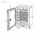
Fig. 1 is a perspective view for explaining a culture apparatus according to an example of this disclosure in a state of opening a heat insulating door. -
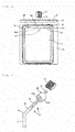
Fig. 2 is a cross-sectional explanatory view in which an incubator is seen from the right side to explain air circulation with focusing on a culture space and a duct in the culture apparatus according to the example of this disclosure. -
Fig. 3 is a perspective view for explaining the relationship between a heat transfer condensation member and a humidification water reservoir in the culture apparatus according to the example of this disclosure. -
Fig. 4 is a front view for explaining the relationship between the heat transfer condensation member and the humidification water reservoir in the culture apparatus according to the example of this disclosure. -
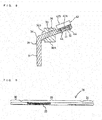
Fig. 5 is a side cross-sectional view for explaining the relationship between the heat transfer condensation member and the humidification water reservoir in the culture apparatus according to the example of this disclosure. -
Fig. 6 is a plan view for explaining the relationship between the heat transfer condensation member and the humidification water reservoir in the culture apparatus according to the example of this disclosure. -
Fig. 7 is an exploded perspective view showing the relationship among the heat transfer condensation member, a heatsink, an electronic cooling element, and a heat insulating member in the culture apparatus according to the example of this disclosure. -
Fig. 8 is a cross-sectional view for explaining the mounting position of the electronic cooling element and the heatsink on the heat transfer condensation member in the culture apparatus according to the example of this disclosure. -
Fig. 9 is an explanatory view for explaining a heat pipe to be used as the heat transfer condensation member in the example of this disclosure. -
Fig. 10 is a side cross-sectional view for explaining the relationship between the heat transfer condensation member and the humidification water reservoir in another embodiment of the culture apparatus according to the example of this disclosure. -
Fig. 11 is a cross-sectional explanatory view in which the incubator is seen from the right side to explain the air circulation with focusing on the culture space and the duct in another embodiment of the culture apparatus according to the example of this disclosure. -
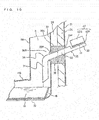
Fig. 12 is a plan view for explaining the relationship in which a cooling portion of the heat transfer condensation member is disposed on an outer box of a heat insulating box main body in a heat conductive state in another embodiment of the culture apparatus according to the example of this disclosure. -
Fig. 13 is a plan view for explaining the relationship in which the cooling portion of the heat transfer condensation member is disposed on a cover member for covering the cooling portion in a heat conductive state in another embodiment of the culture apparatus according to the example of this disclosure. - A
culture apparatus 1 according to an example of this disclosure includes: an approximately box-shaped heat insulating box main body formed with aninner box 22 having aculture space 4 therein to culture a sample such as a cell and a microorganism; ahumidification water reservoir 15 that retains humidification water for controlling the humidity of theculture space 4 and is disposed in the bottom of theculture space 4; and a heattransfer condensation member 35 penetrating the heat insulating boxmain body 2 such that one end is disposed inside theculture space 4 while the other end is disposed outside the heat insulating boxmain body 2. A portion of the heattransfer condensation member 35 that penetrates theinner box 22 and theinner box 22 are disposed with a heat insulatingsealing member 36 interposed therebetween. An extending portion of the heat insulatingsealing member 36 extending into theculture space 4 is formed with an inclined surface inclined obliquely downward in a forward direction so as to lead condensed water adhering to the periphery of the extending portion into thehumidification water reservoir 15. Embodiments of this disclosure will be hereinafter described in detail based on the drawings. - The
culture apparatus 1 according to an embodiment of this disclosure will be described with reference toFigs. 1 to 9 . As shown inFigs. 1 and2 , theculture apparatus 1 according to the embodiment of this disclosure has a left open door (more specifically, anouter door 7 and an inner door 3). The heat insulating boxmain body 2 having an opening 2A in its front face is approximately in the shape of a box formed with theculture space 4 therein to culture the sample such as a cell and a microorganism. One of the structures, as shown in the drawings, is constituted by a metalouter box 21, aheat insulating material 24 disposed inside theouter box 21, and the front side opened stainlessinner box 22 disposed therein with leaving an air layer (so-called air jacket) 25. Thus, theinner box 22 forms the front side openedculture space 4 in the heat insulating boxmain body 2, serving as an area to culture the sample such as a cell and a microorganism.Heaters 37 are disposed on both left and right side faces, a top face, a bottom face, and a back face of theinner box 22 to heat theculture space 4. - As described above, the
culture space 4 for culturing the sample such as a cell and a microorganism is formed in the heat insulating boxmain body 2 having the opening 2A in its front face. Theheat insulating door 7 is attached in an openable and closable manner to one side (left side in the drawing) of the heat insulating boxmain body 2 as the outer door to keep heat out of theculture space 4 through thefront face opening 2A. A loop-shaped gasket 8 with a magnet is disposed in the outer edge of theheat insulating door 7 on a back side. Closing theheat insulating door 7 brings thegasket 8 into tight contact with the outer edge of thefront face opening 2A of the heat insulating boxmain body 2, so that theheat insulating door 7 closes the front face opening 2A in an air-tight manner and keeps outside air out of theculture space 4 through thefront face opening 2A. - The
culture space 4 is partitioned with the front side opened stainlessinner box 22. Both the left and right side faces, the top face, and the back face of theinner box 22 are disposed in the heat insulating boxmain body 2 with leaving the air layer (so-called air jacket) 25 between each face and the heat insulating boxmain body 2. A front face opening of theinner box 22 is opened and closed with thetransparent door 3 as the inner door. Theculture space 4 is substantially formed from a space enclosed with theinner box 22 and thetransparent door 3. Thetransparent door 3 is hinged on theinner box 22 at its left side in an openable and closable manner. An elastic sealing member 2B is disposed in a looped manner at the peripheral edge of the front face opening of theinner box 22. Upon closing the transparentinner door 3, the back side of the transparentinner door 3 comes into tight contact with the elastic sealing member 2B and thus closes the front face opening of theculture space 4. - The
culture space 4 is partitioned vertically with a plurality of shelfs 5 (here, into five with four shelfs). If theculture apparatus 1 is, for example, a CO2 incubator, the concentration of CO2 is normally set and kept at the order of 5%, and a CO2 gas is supplied into theculture space 4 after closing the doors to control the concentration of CO2. - In the
culture space 4, a duct 11 including aback duct 11A and abottom duct 11B is disposed with leaving a space with a back wall and a bottom wall of theinner box 22, to form a gas conduit K of air containing CO2 and the like along the back face and the bottom face. To perform forced circulation of air, a gas containing CO2 and the like in theculture space 4 is sucked from asuction port 12 formed at the top of theback duct 11A, and blown into theculture space 4 fromoutlet ports 13 provided at the front and side faces of thebottom duct 11B. Acirculation blower 14 is disposed inside the duct 11 (here, at the top) to perform the forced circulation of the gas containing CO2 and the like. Thisblower 14 is constituted by afan 14A, a motor 14B, and a shaft 14C. The motor 14B is disposed in amachine chamber 19 on the outside back face of the heat insulating boxmain body 2, to be described later. The shaft 14C extends from the motor 14B disposed in themachine chamber 19 through the back face of the heat insulating boxmain body 2 into the gas conduit K of CO2 and the like and is coupled to thefan 14A. - As the
humidification water reservoir 15 for humidifying theculture space 4, the top face openedhumidification water reservoir 15 is put in the duct 11 that is on the bottom of theculture space 4 and between thebottom duct 11B and the bottom wall of theinner box 22, to store water for humidification (that is, humidification water) 16. The water is heated and evaporated by theheater 37 disposed on the outside bottom face of the metal, e.g., stainless,inner box 22. It is noted that disposing thehumidification water reservoir 15 in the duct 11 and on the bottom of theculture space 4 facilitates circulating humidified gas with high efficiency through the gas conduit K of CO2 and the like, which is formed from thecirculation blower 14 and the duct 11. - The
machine chamber 19, which contains the motor being drive means for thecirculation blower 14, gas supply means 17 for supplying the CO2 gas to theculture space 4, and anelectrical component box 38 to accommodate electrical components such as a not-shown control board and the like, is formed of arear cover 26, for covering the back face of theouter box 21, on the back face of theouter box 21 of the heat insulating boxmain body 2. - The gas supply means 17 includes a
gas supply pipe 17A, anopenable valve 17B, afilter 17C, and the like. A tip end portion of thegas supply pipe 17A faces to the gas conduit K. - The CO2 gas supplied from the
gas supply pipe 17A can be ejected to control the gas concentration of theculture space 4. To obtain a bactericidal effect on the gas flowing in theculture space 4 and thewater 16 in thehumidification water reservoir 15, anultraviolet lamp 27 is disposed in the gas conduit K. - As shown in
Fig. 2 and the like, the heattransfer condensation member 35 in which acondensation portion 31 at one end and a coolingportion 32 at the other end are integrated through aconnection portion 30 is attached to a predetermined position of theculture apparatus 1. The heattransfer condensation member 35 may be any of a heat pipe in which an operating fluid is sealed, a round bar of a predetermined length made of a heat conductive material such as aluminum, and a flat plate of a predetermined length made of a heat conductive material such as aluminum. -
Fig. 9 shows the structure of aheat pipe 35, which is a kind of heattransfer condensation member 35. Theheat pipe 35 has a bar-shaped airtight container in which a little amount of liquid (operating fluid) is vacuum-sealed, and a capillary structure (wicks) 33 in its inner wall. The operating fluid is evaporated at the condensation portion 31 (absorbs latent heat of vaporization), and the evaporated vapor moves to the direction of the coolingportion 32. The vapor is condensed to release the latent heat of vaporization at the coolingportion 32. The condensed fluid is refluxed to thecondensation portion 31 by a capillary phenomenon. Such a series of phase changes occurs in a sequential manner, thus accelerating heat transfer. - To accelerate the heat transfer in the heat
transfer condensation member 35, theheat pipe 35 is preferably used. However, in a case where extremely short-time heat transfer is not necessarily required, just as with theculture apparatus 1, the heattransfer condensation member 35 may be any of the round bar of a predetermined length made of the metallic heat conductive material such as aluminum and silver and the flat plate of a predetermined length made of the heat conductive material such as aluminum and silver. In the case of aluminum, an antiproliferative effect on germs is obtained by forming an antibacterial coating on the surface of the heattransfer condensation member 35 by antibacterial plating, antibacterial alumite, or the like. It is conceivable to use a copper material for the heattransfer condensation member 35, but the copper is likely to form patina and therefore requires a plating process and the like to prevent the patina from appearing in its surface. - The following embodiments describe the case of adopting the heat
transfer condensation member 35 that is made of the round bar of a predetermined length made of the heat conductive material such as aluminum, which is a kind of heattransfer condensation member 35. - The heat
transfer condensation member 35 is attached such that the coolingportion 32 is disposed outside the heat insulating boxmain body 2, that theconnection portion 30 is disposed in theculture space 4 in the heat insulating boxmain body 2 through the heat insulating boxmain body 2 and theinner box 22, and that thecondensation portion 31 is disposed in the gas conduit K in theduct 11A. The coolingportion 32 is disposed in themachine chamber 19 on the back side of theculture apparatus 1 so as not to be damaged by external forces from the vicinity of theculture apparatus 1. - At a portion of the
connection portion 30 that penetrates the heat insulating boxmain body 2 and theinner box 22, theconnection portion 30 is disposed at least between the metalouter box 21 and the stainlessinner box 22 with the heat insulating sealingmember 36 interposed therebetween. The interposition of the heat insulating sealingmember 36 prevents the gas flowing through the gas conduit K from leaking and adversely affecting theculture space 4, and prevents the occurrence of condensation on a contact portion between theconnection portion 30 and theinner box 22. It is also possible to reduce thermal effects on theouter box 21 and theinner box 22. - To keep the
condensation portion 31 at a dew-point temperature and cause condensation on the surface of thecondensation portion 31, the coolingportion 32 is cooled to an appropriate temperature. The cooling effect is transmitted to thecondensation portion 31 through theconnection portion 30, so that thecondensation portion 31 is kept at the dew-point temperature. For this reason, anelectronic cooling device 40 is attached to the coolingportion 32 to cool the coolingportion 32 to the appropriate temperature. For the sake of achieving ease of attachment, miniaturization, ease of temperature control, and the like, in an example of this disclosure, anelectronic cooling element 41 called Peltier element for cooling the coolingportion 32 by the Peltier effect and aheatsink 42 for dissipating heat of theelectronic cooling element 41 are provided as theelectronic cooling device 40. - In the
electronic cooling element 41 called the Peltier element, a plurality of p-n junction semiconductor devices constitute a cooling and heating portion. In a state where n-type semiconductors and p-type semiconductors are arrayed alternately in a lateral direction, a heat absorbing portion (cooling side) is made by coupling an end of the n-type semiconductor to an end of the adjoining p-type semiconductor with a heat conductive plate, and a heat radiating portion (heating side) is made by coupling the other end of the n-type semiconductor to the other end of the adjoining p-type semiconductor with a heat conductive plate. Therefore, on the basis of this relationship, theelectronic cooling element 41 has a well-known structure in which the n-type semiconductors and the p-type semiconductors are connected in series as a whole. - The
heatsink 42, made of aluminum, has a plate-shapedbase 42A and a plurality of plate-shaped radiatingfins 42B formed on the top face of the plate-shapedbase 42A with leaving space in an integral manner. - As shown in
Figs. 7 and8 , the heat absorbing portion (cooling side) of theelectronic cooling element 41 is attached to the top face of the coolingportion 32 of the heattransfer condensation member 35 in a heat conductive state. Thus, the coolingportion 32 of the heattransfer condensation member 35 is formed with a flat attachment surface on its top face. On the attachment surface, the cooling side of theelectronic cooling element 41 is disposed with a heat radiating grease or a heat conductive member such as a thin heat conductive rubber sheet interposed therebetween. On the other hand, the plate-shapedbase 42A of theheatsink 42, which functions as a radiator, is disposed on the heat radiating portion (heating side) of theelectronic cooling element 41 with a heat radiating grease or a heat conductive member such as a thin heat conductive rubber sheet interposed therebetween. In this state, as shown inFigs. 7 and8 , mountingscrews 44 are secured to the plate-shapedbase 42A of theheatsink 42 through the coolingportion 32 from below the coolingportion 32 of the heattransfer condensation member 35 for coupling. Thereby, the coolingportion 32 of the heattransfer condensation member 35, theelectronic cooling element 41, and theheatsink 42 are integrated into one unit in a heat conductive state. - To keep the
condensation portion 31 of the heattransfer condensation member 35 at the dew-point temperature and cause condensation on the surface of thecondensation portion 31, the coolingportion 32 is cooled by theelectronic cooling element 41. The coolingportion 32 is disposed on the side of theelectrical component box 38 in such a position as to be little affected by heat generated by heat generating components in theelectrical component box 38. - As shown in
Fig. 5 , theconnection portion 30 of the heattransfer condensation member 35 penetrates a throughhole 21P of theouter box 21, the heat insulating sealingmember 36, and a throughhole 22P of theinner box 22, without being in contact with theouter box 21 and theinner box 22. As shown in the drawings, the heat insulating sealingmember 36 is preferably a one-unit member with high hydrophobicity into which amain body portion 36A (second heat insulating sealingmember 36A) and atip sealing portion 36B (first heat insulating sealingmember 36B) at a tip thereof are molded, and the heat insulating sealingmember 36 is made of a polyacetal resin, by way of example. As a hydrophobic material, there may be adopted a hydrophobic rubber, a fluororesin, or the like. Themain body portion 36A of the heat insulating sealingmember 36 is in contact with an inner side face of a back wall of theouter box 21 so as to fill the throughhole 21P at its back face, and is in contact with a back face of the back wall of theinner box 22 while penetrating theheat insulating material 24. Thetip sealing portion 36B extending forward from themain body portion 36A penetrates the throughhole 22P of theinner box 22 into the gas conduit K. - As shown in the drawings, the heat
transfer condensation member 35 is held in an inclined state such that theconnection portion 30 descends from back to front while penetrating themain body portion 36A and thetip sealing portion 36B of the heat insulating sealingmember 36. The heat insulating sealingmember 36 prevents the gas flowing through the gas conduit K from leaking from the position of the heattransfer condensation member 35, and prevents the adverse effects of the gas leakage on theculture space 4. The heat insulating sealingmember 36 also suppresses the occurrence of condensation on theinner box 22 through theconnection portion 30 of the heattransfer condensation member 35, and reduces the thermal effects of theouter box 21 and theinner box 22 on the heattransfer condensation member 35. - In order to make moisture that is condensed on the
condensation portion 31 and theconnection portion 30 in the vicinity thereof flow downward into thehumidification water reservoir 15, the heattransfer condensation member 35 is formed with abend portion 34 by bending downward theconnection portion 30 at a portion that reaches the gas conduit K in theduct 11A. A portion of the heattransfer condensation member 35 that extends from thebend portion 34 to thecondensation portion 31 is formed downward in parallel with theduct 11A corresponding thereto. Also, in order to make moisture condensed on a portion of the heat insulating sealingmember 36 that extends into the duct 11, that is, moisture condensed on thetip sealing portion 36B exposed to the gas conduit K flow downward into thehumidification water reservoir 15, the peripheral surface of thetip sealing portion 36B, including not only top and bottom surfaces but also left and right surfaces, takes the form of an inclined surface extending obliquely downward in a forward direction so as to extend directly above thehumidification water reservoir 15. - Therefore, condensation tends to occur on the portion of the heat
transfer condensation member 35 that extends from thebend portion 34 to thecondensation portion 31, and the condensed moisture flows downward by gravity and drops into thehumidification water reservoir 15 without dispersal. Even in a case where condensation occurs on thetip sealing portion 36B of the heat insulating sealingmember 36 exposed to the gas conduit K, the condensed moisture flows downward along the inclination by gravity and drops into thehumidification water reservoir 15 directly or through theconnection portion 30 and thecondensation portion 31, and therefore drops into thehumidification water reservoir 15 without dispersal. -
Fig. 10 shows another embodiment. Since components denoted by the same reference numerals as those ofFigs. 1 to 9 have the same functions, the detailed description thereof will be omitted and a different structure will be described. A tip end of thecondensation portion 31 is inclined toward the inside of thehumidification water reservoir 15, and disposed in such a position that a lowermost end of thecondensation portion 31 is situated inside thehumidification water reservoir 15 with respect to the edge of thehumidification water reservoir 15 in a horizontal direction, in other words, condensed moisture is sure to drop into thehumidification water reservoir 15 when flowing downward by gravity. That is to say, the tip end of thecondensation portion 31 is inclined so as to be away from the back face of the heat insulating boxmain body 2. Thereby, even if thecondensation portion 31 is brought near to the vicinity of the back face of the heat insulating boxmain body 2, it is possible to keep a certain distance between the lowermost end of thecondensation portion 31 and the back face of the heat insulating boxmain body 2. It is noted that the heattransfer condensation member 35 penetrates the back face of the heat insulating boxmain body 2 in the example of this disclosure, but may penetrate a side face thereof. -
Fig. 11 shows yet another embodiment. The heattransfer condensation member 35 shown inFig. 11 is disposed horizontally, instead of being disposed in an inclined manner with lowering its front side. To be more specific, the heattransfer condensation member 35 is attached so as to dispose the coolingportion 32 outside the heat insulating boxmain body 2, dispose theconnection portion 30 horizontally through the heat insulating boxmain body 2 and theinner box 22, and dispose thecondensation portion 31 in the gas conduit K in theduct 11A. The coolingportion 32 is disposed in themachine chamber 19 of theculture apparatus 1 so as not to be damaged by external forces from the vicinity of theculture apparatus 1. - In a portion of the
connection portion 30 that penetrates theinner box 22, the heat insulating sealingmember 36 is disposed between the stainlessinner box 22 and theconnection portion 30. As in the same manner as described above, the heat insulating sealingmember 36 is made of a synthetic resin, into which themain body portion 36A and thetip sealing portion 36B at the tip of themain body portion 36A are integrally molded. Themain body portion 36A is in contact with the inner side face of the back wall of theouter box 21 at its back face, and is in contact with the back face of the back wall of theinner box 22 through theheat insulating material 24. Thetip sealing portion 36B extending forward from themain body portion 36A extends into the gas conduit K through the back wall of theinner box 22. As shown in the drawings, the heattransfer condensation member 35 is held in such a manner that theconnection portion 30 thereof is horizontal from back to front while penetrating themain body portion 36A and thetip sealing portion 36B of the heat insulating sealingmember 36. - In order to make moisture that is condensed on the
condensation portion 31 and theconnection portion 30 in the vicinity thereof flow downward into thehumidification water reservoir 15, the heattransfer condensation member 35 is formed with thebend portion 34 by bending downward theconnection portion 30 at a portion that reaches the gas conduit K in theduct 11A. A portion of the heattransfer condensation member 35 that extends from thebend portion 34 to aheat inlet portion 31 is formed downward in parallel with theduct 11A corresponding thereto. Also, in order to make moisture condensed on a portion of the heat insulating sealingmember 36 that extends into the duct 11, that is, moisture condensed on thetip sealing portion 36B exposed to the gas conduit K flow downward into thehumidification water reservoir 15, the peripheral surface of thetip sealing portion 36B, including not only top and bottom surfaces but also left and right surfaces, takes the form of an inclined surface extending obliquely downward in a forward direction so as to extend directly above thehumidification water reservoir 15. - Therefore, condensation tends to occur on the portion of the heat
transfer condensation member 35 that extends from thebend portion 34 to thecondensation portion 31, and the condensed moisture flows downward by gravity and drops into thehumidification water reservoir 15 without dispersal. Even in a case where condensation occurs on thetip sealing portion 36B of the heat insulating sealingmember 36 exposed to the gas conduit K, the condensed moisture flows downward along the inclination by gravity and drops into thehumidification water reservoir 15 directly or through theconnection portion 30 and thecondensation portion 31, and therefore drops into thehumidification water reservoir 15 without dispersal. - As described above, in the example of this disclosure shown in
Figs. 1 to 13 , since the heat insulating sealingmember 36 is disposed between a portion of theconnection portion 30 that penetrates theinner box 22 and the stainlessinner box 22, the gas flowing through the gas conduit K does not leak from the position of the heattransfer condensation member 35, thus preventing the adverse effects of the gas leakage on theculture space 4. It is also possible to suppress condensation on theinner box 22 through theconnection portion 30 of the heattransfer condensation member 35, and suppress the thermal effects of theouter box 21 and theinner box 22 on the heattransfer condensation member 35. - As in the same manner as described above, the heat absorbing portion (cooling portion) of the
electronic cooling element 41 is attached to the coolingportion 32 of the heattransfer condensation member 35 in a heat conductive state. Thus, exerting the same control as described above causes condensation on the surface of thecondensation portion 31, and hence the condensed water is led into thehumidification water reservoir 15 and reused for humidification. - In the above disclosed technique, in a case where the
electronic cooling element 41 promotes heat dissipation from the coolingportion 32 of the heattransfer condensation member 35, making a drive voltage of theelectronic cooling element 41 variable on the basis of an ambient temperature of theculture apparatus 1 and the like has the effect of controlling a temperature state so as to cause condensation on the surface of thecondensation portion 31. However, the coolingportion 32 of the heattransfer condensation member 35 may be extended and attached in contact with a left side face, a right side face, or a back face of therear cover 26 for covering themachine chamber 19 through a heat radiating grease or a heat conductive member such as a thin heat conductive rubber sheet, instead of providing theelectronic cooling element 41, to thereby dissipate heat of the coolingportion 32 of the heattransfer condensation member 35 through therear cover 26. - Forming the cooling
portion 32 in such a shape as to be in contact with a plurality of surfaces of theouter box 21 and attaching the coolingportion 32 in contact with theouter box 21 through a heat radiating grease or a heat conductive member such as a thin heat conductive rubber sheet make it possible to dissipate heat of the coolingportion 32 through theouter box 21. The heat dissipation from the coolingportion 32 cools thecondensation portion 31, and moisture condensed on the surface of thecondensation portion 31 is led into thehumidification water reservoir 15 disposed beneath. - The size, shape, dimensions, number, and the like of the heat transfer condensation member to be used in this disclosure are variable in accordance with the capacity, shape, and size of the culture apparatus, the culture material, and the like.
- It is noted that the above-described embodiments describe the example of this disclosure, but neither limit the invention included in the scope of the claims nor narrow the scope of the claims. The structure of each component in the example of this disclosure is not limited to the above-described embodiments, but variously modified within the technical scope described in the scope of the claims.
- As described above, the
culture apparatuses 1 according to the embodiments have at least the following effects. - The
culture apparatus 1 according to the embodiment includes: the heat insulating boxmain body 2 approximately in a box shape, formed with theculture space 4 therein for culturing a sample such as a cell and a microorganism; thehumidification water reservoir 15 disposed in the bottom of theculture space 4, thehumidification water reservoir 15 storing the humidification water to control the humidity of theculture space 4; and the heattransfer condensation member 35 penetrating the heat insulating boxmain body 2 in such a manner that one end is disposed inside theculture space 4 while the other end is disposed outside the heat insulating boxmain body 2. The heattransfer condensation member 35 is positioned such that the connection portion 30 (condensation portion) disposed inside theculture space 4 is inclined downward to the one end, and the one end leads condensed water condensed on the surfaces of theconnection portion 30 and thecondensation portion 31 into thehumidification water reservoir 15. - Therefore, since moisture condensed on the
connection portion 30 and thecondensation portion 31 is caused to flow downward into thehumidification water reservoir 15 and is reusable repeatedly as thehumidification water 16, it is possible to suppress condensation on the inner walls of theculture space 4 and hence suppress adverse effects on the culture material. - In the
culture apparatus 1 according to the embodiment, the heat insulating boxmain body 2 has the approximately box-shapedinner box 22 for forming theculture space 4 and the approximately box-shapedouter box 21 enclosing the outer periphery of theinner box 22, and the heat insulating sealing member 36 (first heat insulating sealing member) with heat insulating properties and hydrophobic properties is disposed between theinner box 22 and a portion of the heattransfer condensation member 35 that penetrates a side face of theinner box 22. - Thus, due to the hydrophobic properties of the heat insulating sealing
member 36, condensed water condensed on the heat insulating sealingmember 36 can be caused to promptly flow downward. Furthermore, due to the heat insulating properties of the heat insulating sealingmember 36, it is possible to suppress condensation on theinner box 22 through the heattransfer condensation member 35, and suppress thermal effects of theinner box 22 on the heattransfer condensation member 35. - In the
culture apparatus 1 according to the embodiment, thetip sealing portion 36B (extending portion) of the heat insulating sealingmember 36 that extends into theculture space 4 is inclined downward to the one end of the heattransfer condensation member 35, to lead condensed water adhering to the periphery of thetip sealing portion 36B into thehumidification water reservoir 15. - Thus, since condensation on the
tip sealing portion 36B of the heat insulating sealingmember 36 that extends into theculture space 4 can be promptly led into thehumidification water reservoir 15 without dispersal, it is possible to suppress condensation on the walls of theculture space 4 and hence suppress adverse effects on the culture material, and furthermore repeatedly reuse water led into thehumidification water reservoir 15 as the humidification water. - The
culture apparatus 1 according to the embodiment includes: the heat insulating boxmain body 2 approximately in a box shape, formed with theculture space 4 therein for culturing a sample such as a cell and a microorganism; thehumidification water reservoir 15 disposed in the bottom of theculture space 4, thehumidification water reservoir 15 storing the humidification water to control the humidity of theculture space 4; and the heattransfer condensation member 35 penetrating the side face of the heat insulating boxmain body 2 in such a manner that one end is disposed inside theculture space 4 while the other end is disposed outside the heat insulating boxmain body 2. The heattransfer condensation member 35 is positioned such that an end of thecondensation portion 31 disposed inside the culture space leads condensed water condensed on the surface of thecondensation portion 31 into thehumidification water reservoir 15. The heat insulating boxmain body 2 has the approximately box-shapedinner box 22 for forming theculture space 4 and the approximately box-shapedouter box 21 enclosing the outer periphery of theinner box 22. The heat insulating sealingmember 36 with heat insulating properties and hydrophobic properties is disposed between theinner box 22 and a portion of the heattransfer condensation member 35 that penetrates theinner box 22. In the heat insulating sealingmember 36B, thetip sealing portion 36B (extending portion) extending into theculture space 4 is inclined downward to the one end of the heattransfer condensation member 35, to lead condensed water adhering to the periphery of thetip sealing portion 36B into thehumidification water reservoir 15. - Therefore, even if the
connection portion 30 of the heattransfer condensation member 35 is not inclined, as shown in the embodiment ofFig. 10 , since thetip sealing portion 36B is inclined downward in the forward direction, condensed water condensed on the heat insulating sealingmember 36 promptly flows downward. Furthermore, due to the heat insulating properties of the heat insulating sealingmember 36, it is possible to suppress condensation on theinner box 22 through the heattransfer condensation member 35, and suppress thermal effects of theinner box 22 on the heattransfer condensation member 35. In a case where theconnection portion 30 is horizontal, thetip sealing portion 36B preferably covers almost all of thehorizontal connection portion 30 in theculture space 4 and extends to thebend portion 34 or thecondensation portion 31. This facilitates the prompt flow of the condensed water. - In the
culture apparatus 1 according to the embodiment, the second heat insulating sealingmember 36A with heat insulating properties covers a portion of the heattransfer condensation member 35 that is disposed between theouter box 21 and theinner box 22. - Therefore, the portion of the heat
transfer condensation member 35 that is disposed between theouter box 21 and theinner box 22 is hardly affected by the temperature of theinner box 22 and theouter box 21, and hence has a sufficient condensation effect on the portion extending into theculture space 4. - In the
culture apparatus 1 according to the embodiment, the first heat insulating sealingmember 36B and the second heat insulating sealingmember 36A are integrated into one unit. - Thus, it is possible to facilitate formation and attachment processes of the heat insulating sealing member, which effectively suppresses the temperature effect of surroundings on the heat
transfer condensation member 35 and promotes a flow of condensed water downward to the extending portion extending into theculture space 4, thus resulting in cost reduction. - In the
culture apparatus 1 according to the embodiment, the heattransfer condensation member 35 is provided with anelectronic cooling element 41 that can cool the heattransfer condensation member 35 by the Peltier effect at a coolingportion 32 disposed outside the heat insulating boxmain body 2, and moisture condensed on the surface of thecondensation portion 31 by cooling by theelectronic cooling element 41 is led into thehumidification water reservoir 15 disposed beneath. - Therefore, it is possible to have control over the temperature so as to cause condensation on the surface of the
condensation portion 31, by varying the drive voltage of theelectronic cooling element 41. - In the
culture apparatus 1 according to another embodiment, the tip end of thecondensation portion 31 is inclined toward the inside of thehumidification water reservoir 15. In other words, the tip end of thecondensation portion 31 is inclined so as to be away from the back face of the heat insulating boxmain body 2. - Thereby, even if the
condensation portion 31 is brought near to the vicinity of the back face of the heat insulating boxmain body 2, condensed water is reliably caused to flow downward into thehumidification water reservoir 15. - In the
culture apparatus 1 according to another of the embodiments, as shown inFig. 12 , contact of the coolingportion 32 disposed outside the heat insulating boxmain body 2 with theouter box 21 facilitates heat dissipation of the heattransfer condensation member 35, and the heat dissipation from the coolingportion 32 cools thecondensation portion 31, so that moisture condensed on the surface of thecondensation portion 31 is led into thehumidification water reservoir 15 disposed beneath. - Thus, utilizing the
outer box 21 for the heat dissipation of the coolingportion 32 eliminates the need for providing theelectronic cooling element 41, thus resulting in cost reduction. - The cooling
portion 32 preferably is caused to be in contact with theouter box 21 through the heat radiating grease or the heat conductive member such as the thin heat conductive rubber sheet. - Thus, heat is effectively dissipated from the cooling
portion 32 through theouter box 21. - In the
culture apparatus 1 according to another embodiment, at least acover member 26 for covering the coolingportion 32 of the heattransfer condensation member 35 is provided outside the heat insulating boxmain body 2. As shown inFig. 13 , heat is dissipated from the coolingportion 32 by the contact with thecover member 26. The heat dissipation from the coolingportion 32 cools thecondensation portion 31, and thus moisture condensed on the surface of thecondensation portion 31 is led into thehumidification water reservoir 15 disposed beneath. - Therefore, the
cover member 26 protects the coolingportion 32 from damage by external forces from the vicinity of theculture apparatus 1. Also, utilizing thecover member 26 for the heat dissipation of the coolingportion 32 eliminates the need for providing theelectronic cooling element 41, thus resulting in cost reduction. - The cooling portion is preferably caused to be in contact with the
cover member 26 through the heat radiating grease or the heat conductive member such as the thin heat conductive rubber sheet. - Thus, heat is effectively dissipated from the cooling
portion 32 through thecover member 26. - The culture apparatus according to the example of this disclosure is configured such that the heat transfer condensation member having the condensation portion and the cooling portion is attached to a predetermined position, and for example, the inside vapor density of the culture space closing to the density of over-saturated water vapor causes condensation on the condensation portion, and the condensed moisture flows downward into the humidification water reservoir so as to be repeatedly usable as the humidification water. Therefore, the culture apparatus has the significant effects of suppressing adverse effects on a culture material by suppressing the condensation, allowing operation of the culture space without the occurrence of temperature and humidity variations by operating the circular blower in the duct, and providing the economical culture apparatus without increased manufacturing costs, thus having a great deal of potential in industry.
-
- 1
- culture apparatus
- 2
- heat insulating box main body
- 2A
- opening
- 3
- transparent inner door
- 4
- culture space
- 5
- shelf
- 7
- heat insulating door
- 8
- gasket
- 11
- duct
- 11A
- back duct
- 11B
- bottom duct
- 14
- circulation blower
- 15
- humidification water reservoir
- 16
- humidification water
- 17
- gas supply means
- 17A
- gas supply pipe
- 21
- outer box
- 22
- inner box
- 24
- heat insulating material
- 25
- air layer (air jacket)
- 30
- connection portion
- 31
- condensation portion
- 32
- cooling portion
- 33
- capillary structure (wicks)
- 34
- bend portion
- 35
- heat transfer condensation member
- 36
- heat insulating sealing member
- 36A
- main body portion of heat insulating sealing member (second heat insulating sealing member)
- 36B
- tip sealing portion of heat insulating sealing member (first heat insulating sealing member)
- 40
- electronic cooling device
- 41
- electronic cooling element
- 42
- heatsink
Claims (18)
- A culture apparatus comprising:a heat insulating box main body approximately in a box shape, formed with a culture space therein for culturing a sample such as a cell and a microorganism;a humidification water reservoir disposed in a bottom of the culture space, the humidification water reservoir storing humidification water to control humidity of the culture space; anda heat transfer condensation member penetrating the heat insulating box main body in such a manner that one end is disposed inside the culture space while the other end is disposed outside the heat insulating box main body, whereinthe heat transfer condensation member is positioned such that a condensation portion disposed inside the culture space is inclined downward to the one end, and the one end leads condensed water condensed on a surface of the condensation portion into the humidification water reservoir.
- The culture apparatus according to claim 1, wherein the heat insulating box main body has an approximately box-shaped inner box for forming the culture space and an approximately box-shaped outer box enclosing an outer periphery of the inner box, and a first heat insulating sealing member with heat insulating properties and hydrophobic properties is disposed between the inner box and a portion of the heat transfer condensation member that penetrates the inner box.
- The culture apparatus according to claim 2, wherein the first heat insulating sealing member has an extending portion that extends into the culture space and that is inclined downward to the one end of the heat transfer condensation member, to lead condensed water adhering to a periphery of the extending portion into the humidification water reservoir.
- The culture apparatus according to any one of claims 1 to 3, wherein a tip of the one end is inclined toward the inside of the humidification water reservoir, and a lowermost end of the tip is disposed inside the humidification water reservoir in a horizontal direction with respect to an edge of the humidification water reservoir.
- The culture apparatus according to claim 3 or 4, wherein a second heat insulating sealing member with heat insulating properties covers a portion of the heat transfer condensation member that is disposed between the outer box and the inner box.
- The culture apparatus according to claim 5, wherein the first heat insulating sealing member and the second heat insulating sealing member are integrated into one unit.
- The culture apparatus according to one of claims 1 to 6, wherein the heat transfer condensation member is provided with an electronic cooling element that can cool the heat transfer condensation member by the Peltier effect at a cooling portion disposed outside the heat insulating box main body, and moisture condensed on the surface of the condensation portion by cooling by the electronic cooling element is led into the humidification water reservoir disposed beneath.
- The culture apparatus according to claim 7, wherein heat is dissipated from the heat transfer condensation member by contact of the cooling portion disposed outside the heat insulating box main body with the outer box, and the moisture condensed on the surface of the condensation portion by cooling the condensation portion by heat dissipation from the cooling portion is led into the humidification water reservoir disposed beneath.
- The culture apparatus according to claim 7, wherein a cover member for covering at least the cooling portion of the heat transfer condensation member is provided outside the heat insulating box main body, heat is dissipated from the cooling portion by contact with the cover member, and the moisture condensed on the surface of the condensation portion by cooling the condensation portion by heat dissipation from the cooling portion is led into the humidification water reservoir disposed beneath.
- A culture apparatus comprising:a heat insulating box main body approximately in a box shape, formed with a culture space therein for culturing a sample such as a cell and a microorganism;a humidification water reservoir disposed in a bottom of the culture space, the humidification water reservoir storing humidification water to control humidity of the culture space; anda heat transfer condensation member penetrating the heat insulating box main body in such a manner that one end is disposed inside the culture space while the other end is disposed outside the heat insulating box main body, whereinthe heat transfer condensation member is positioned such that the one end of a condensation portion disposed inside the culture space leads condensed water condensed on a surface of the condensation portion into the humidification water reservoir;the heat insulating box main body has an approximately box-shaped inner box for forming the culture space and an approximately box-shaped outer box enclosing an outer periphery of the inner box;a first heat insulating sealing member with heat insulating properties and hydrophobic properties is disposed between the inner box and a portion of the heat transfer condensation member that penetrates the inner box; andthe first heat insulating sealing member is configured such that an extending portion extending into the culture space is inclined downward to the one end of the heat transfer condensation member, to lead condensed water adhering to a periphery of the extending portion into the humidification water reservoir.
- The culture apparatus according to claim 10, wherein the heat insulating box main body has the approximately box-shaped inner box for forming the culture space and the approximately box-shaped outer box enclosing the outer periphery of the inner box, and the first heat insulating sealing member with the heat insulating properties and the hydrophobic properties is disposed between the inner box and the portion of the heat transfer condensation member that penetrates the inner box.
- The culture apparatus according to claim 11, wherein the first heat insulating sealing member has an extending portion that extends into the culture space and that is inclined downward to the one end of the heat transfer condensation member, to lead condensed water adhering to a periphery of the extending portion into the humidification water reservoir.
- The culture apparatus according to any one of claims 10 to 12, wherein a tip of the one end is inclined toward the inside of the humidification water reservoir, and a lowermost end of the tip is disposed inside the humidification water reservoir in a horizontal direction with respect to an edge of the humidification water reservoir.
- The culture apparatus according to any one of claims 10 to 13, wherein a second heat insulating sealing member with heat insulating properties covers a portion of the heat transfer condensation member that is disposed between the outer box and the inner box.
- The culture apparatus according to claim 14, wherein the first heat insulating sealing member and the second heat insulating sealing member are integrated into one unit.
- The culture apparatus according to any one of claims 10 to 15, wherein the heat transfer condensation member is provided with an electronic cooling element that can cool the heat transfer condensation member by the Peltier effect at a cooling portion disposed outside the heat insulating box main body, and moisture condensed on the surface of the condensation portion by cooling by the electronic cooling element is led into the humidification water reservoir disposed beneath.
- The culture apparatus according to claim 16, wherein heat is dissipated from the heat transfer condensation member by contact of the cooling portion disposed outside the heat insulating box main body with the outer box, and the moisture condensed on the surface of the condensation portion by cooling the condensation portion by heat dissipation from the cooling portion is led into the humidification water reservoir disposed beneath.
- The culture apparatus according to claim 16, wherein a cover member for covering at least the cooling portion of the heat transfer condensation member is provided outside the heat insulating box main body, heat is dissipated from the cooling portion by contact with the cover member, and the moisture condensed on the surface of the condensation portion by cooling the condensation portion by heat dissipation from the cooling portion is led into the humidification water reservoir disposed beneath.
Applications Claiming Priority (3)
| Application Number | Priority Date | Filing Date | Title |
|---|---|---|---|
| JP2013059977 | 2013-03-22 | ||
| JP2013196429 | 2013-09-24 | ||
| PCT/JP2014/001633 WO2014148057A1 (en) | 2013-03-22 | 2014-03-20 | Culture apparatus |
Publications (3)
| Publication Number | Publication Date |
|---|---|
| EP2963105A1 true EP2963105A1 (en) | 2016-01-06 |
| EP2963105A4 EP2963105A4 (en) | 2016-03-23 |
| EP2963105B1 EP2963105B1 (en) | 2017-05-03 |
Family
ID=51579754
Family Applications (1)
| Application Number | Title | Priority Date | Filing Date |
|---|---|---|---|
| EP14768583.8A Active EP2963105B1 (en) | 2013-03-22 | 2014-03-20 | Culture apparatus |
Country Status (5)
| Country | Link |
|---|---|
| US (1) | US9677041B2 (en) |
| EP (1) | EP2963105B1 (en) |
| JP (1) | JP5887022B2 (en) |
| CN (1) | CN105073973B (en) |
| WO (1) | WO2014148057A1 (en) |
Cited By (1)
| Publication number | Priority date | Publication date | Assignee | Title |
|---|---|---|---|---|
| EP3369803A1 (en) * | 2017-03-03 | 2018-09-05 | Adolf Kühner AG | Incubator and method for humidifying an incubator |
Families Citing this family (4)
| Publication number | Priority date | Publication date | Assignee | Title |
|---|---|---|---|---|
| JP1565711S (en) * | 2016-02-04 | 2016-12-19 | ||
| WO2020049968A1 (en) * | 2018-09-06 | 2020-03-12 | Phc株式会社 | Culture device |
| CN109974401A (en) * | 2019-04-22 | 2019-07-05 | 东北大学 | A kind of vacuum oven |
| CN112406980A (en) * | 2020-12-18 | 2021-02-26 | 浙江师范大学 | Microbial specimen transfer device |
Family Cites Families (16)
| Publication number | Priority date | Publication date | Assignee | Title |
|---|---|---|---|---|
| US5219020A (en) * | 1990-11-22 | 1993-06-15 | Actronics Kabushiki Kaisha | Structure of micro-heat pipe |
| JPH05227942A (en) | 1992-02-25 | 1993-09-07 | Unie Data:Kk | Apparatus for culturing |
| JP3023637B2 (en) * | 1993-06-08 | 2000-03-21 | 株式会社日立製作所 | Refrigeration control method for constant temperature and humidity apparatus |
| JPH0775552A (en) * | 1993-09-07 | 1995-03-20 | Sanyo Electric Co Ltd | Culture system |
| DE4441250C1 (en) * | 1994-11-19 | 1996-04-25 | Binder Peter Michael | Incubator |
| JP2004303580A (en) * | 2003-03-31 | 2004-10-28 | Nichias Corp | Tape heater |
| JP2005095097A (en) * | 2003-09-26 | 2005-04-14 | Sanyo Electric Co Ltd | Incubator |
| JP2005118021A (en) * | 2003-10-20 | 2005-05-12 | Sanyo Electric Co Ltd | Incubator |
| CN2685343Y (en) * | 2003-12-19 | 2005-03-16 | 上海力申科学仪器有限公司 | CO2 incubator with tilting upside down liner |
| JP5084187B2 (en) * | 2006-06-29 | 2012-11-28 | パナソニックヘルスケア株式会社 | Incubator and humidifier dish for incubator |
| US8073096B2 (en) * | 2007-05-14 | 2011-12-06 | Stc.Unm | Methods and apparatuses for removal and transport of thermal energy |
| DE202009012555U1 (en) * | 2009-09-17 | 2010-03-04 | Kunstwadl, Hans | cooler |
| JP5570191B2 (en) * | 2009-11-30 | 2014-08-13 | パナソニックヘルスケア株式会社 | incubator |
| US20120198859A1 (en) * | 2011-02-03 | 2012-08-09 | Iberica del Espacio, S.A., | Thermal control device |
| JP5908240B2 (en) * | 2011-09-22 | 2016-04-26 | パナソニックヘルスケアホールディングス株式会社 | Incubator |
| JP5897855B2 (en) * | 2011-09-22 | 2016-04-06 | パナソニックヘルスケアホールディングス株式会社 | Incubator with heater |
-
2014
- 2014-03-20 JP JP2015506615A patent/JP5887022B2/en active Active
- 2014-03-20 EP EP14768583.8A patent/EP2963105B1/en active Active
- 2014-03-20 WO PCT/JP2014/001633 patent/WO2014148057A1/en active Application Filing
- 2014-03-20 CN CN201480017434.0A patent/CN105073973B/en active Active
-
2015
- 2015-09-21 US US14/860,477 patent/US9677041B2/en active Active
Cited By (2)
| Publication number | Priority date | Publication date | Assignee | Title |
|---|---|---|---|---|
| EP3369803A1 (en) * | 2017-03-03 | 2018-09-05 | Adolf Kühner AG | Incubator and method for humidifying an incubator |
| US10619129B2 (en) | 2017-03-03 | 2020-04-14 | Adolf Kühner Ag | Method for humidifying an incubator, and incubator |
Also Published As
| Publication number | Publication date |
|---|---|
| US20160010048A1 (en) | 2016-01-14 |
| WO2014148057A1 (en) | 2014-09-25 |
| CN105073973B (en) | 2018-12-28 |
| EP2963105A4 (en) | 2016-03-23 |
| JPWO2014148057A1 (en) | 2017-02-16 |
| CN105073973A (en) | 2015-11-18 |
| EP2963105B1 (en) | 2017-05-03 |
| US9677041B2 (en) | 2017-06-13 |
| JP5887022B2 (en) | 2016-03-16 |
Similar Documents
| Publication | Publication Date | Title |
|---|---|---|
| US9902931B2 (en) | Culture apparatus | |
| US9677041B2 (en) | Culture apparatus with condensation control | |
| US8815579B2 (en) | Culture apparatus provided with heat pipe | |
| JP6401987B2 (en) | Cultivation apparatus and humidity control method | |
| US9459036B2 (en) | Sample cooling device | |
| JP5997207B2 (en) | Control panel cooling device | |
| JP2009231511A (en) | Casing | |
| JP2015023279A (en) | Cabinet for power electronic apparatus | |
| KR20190107724A (en) | panel | |
| JP2010057398A (en) | Culture apparatus | |
| EP3825395B1 (en) | Culture device | |
| JP2011077387A (en) | Electronic device | |
| JP6021423B2 (en) | Heat exchange unit | |
| EP3561039B1 (en) | Accommodation device | |
| US11378496B2 (en) | Device with sample temperature adjustment function | |
| JP2010206098A (en) | Cooling device | |
| US11026353B2 (en) | Arrangement having a housing and a power electronics circuit arranged on a housing base in the housing | |
| JP4837131B2 (en) | Electronics | |
| JP2023054774A (en) | Method and device for cooled chemical material cabinet | |
| US20140016267A1 (en) | Electronic device with heat insulation layer | |
| JP2023012741A (en) | Electronic cooling device | |
| JP4691206B2 (en) | Electronics |
Legal Events
| Date | Code | Title | Description |
|---|---|---|---|
| PUAI | Public reference made under article 153(3) epc to a published international application that has entered the european phase |
Free format text: ORIGINAL CODE: 0009012 |
|
| 17P | Request for examination filed |
Effective date: 20150930 |
|
| AK | Designated contracting states |
Kind code of ref document: A1 Designated state(s): AL AT BE BG CH CY CZ DE DK EE ES FI FR GB GR HR HU IE IS IT LI LT LU LV MC MK MT NL NO PL PT RO RS SE SI SK SM TR |
|
| AX | Request for extension of the european patent |
Extension state: BA ME |
|
| RIC1 | Information provided on ipc code assigned before grant |
Ipc: C12M 1/34 20060101ALI20160211BHEP Ipc: C12M 1/00 20060101AFI20160211BHEP Ipc: C12M 1/36 20060101ALI20160211BHEP |
|
| A4 | Supplementary search report drawn up and despatched |
Effective date: 20160219 |
|
| DAX | Request for extension of the european patent (deleted) | ||
| GRAP | Despatch of communication of intention to grant a patent |
Free format text: ORIGINAL CODE: EPIDOSNIGR1 |
|
| INTG | Intention to grant announced |
Effective date: 20161027 |
|
| RIN1 | Information on inventor provided before grant (corrected) |
Inventor name: TOKUMARU, TOMOYOSHI Inventor name: KOBAYASHI, MASAHIKO |
|
| GRAS | Grant fee paid |
Free format text: ORIGINAL CODE: EPIDOSNIGR3 |
|
| GRAA | (expected) grant |
Free format text: ORIGINAL CODE: 0009210 |
|
| AK | Designated contracting states |
Kind code of ref document: B1 Designated state(s): AL AT BE BG CH CY CZ DE DK EE ES FI FR GB GR HR HU IE IS IT LI LT LU LV MC MK MT NL NO PL PT RO RS SE SI SK SM TR |
|
| REG | Reference to a national code |
Ref country code: GB Ref legal event code: FG4D |
|
| REG | Reference to a national code |
Ref country code: AT Ref legal event code: REF Ref document number: 889995 Country of ref document: AT Kind code of ref document: T Effective date: 20170515 Ref country code: CH Ref legal event code: EP |
|
| REG | Reference to a national code |
Ref country code: IE Ref legal event code: FG4D |
|
| REG | Reference to a national code |
Ref country code: DE Ref legal event code: R096 Ref document number: 602014009484 Country of ref document: DE |
|
| REG | Reference to a national code |
Ref country code: NL Ref legal event code: FP |
|
| REG | Reference to a national code |
Ref country code: AT Ref legal event code: MK05 Ref document number: 889995 Country of ref document: AT Kind code of ref document: T Effective date: 20170503 |
|
| REG | Reference to a national code |
Ref country code: LT Ref legal event code: MG4D |
|
| PG25 | Lapsed in a contracting state [announced via postgrant information from national office to epo] |
Ref country code: ES Free format text: LAPSE BECAUSE OF FAILURE TO SUBMIT A TRANSLATION OF THE DESCRIPTION OR TO PAY THE FEE WITHIN THE PRESCRIBED TIME-LIMIT Effective date: 20170503 Ref country code: NO Free format text: LAPSE BECAUSE OF FAILURE TO SUBMIT A TRANSLATION OF THE DESCRIPTION OR TO PAY THE FEE WITHIN THE PRESCRIBED TIME-LIMIT Effective date: 20170803 Ref country code: FI Free format text: LAPSE BECAUSE OF FAILURE TO SUBMIT A TRANSLATION OF THE DESCRIPTION OR TO PAY THE FEE WITHIN THE PRESCRIBED TIME-LIMIT Effective date: 20170503 Ref country code: LT Free format text: LAPSE BECAUSE OF FAILURE TO SUBMIT A TRANSLATION OF THE DESCRIPTION OR TO PAY THE FEE WITHIN THE PRESCRIBED TIME-LIMIT Effective date: 20170503 Ref country code: GR Free format text: LAPSE BECAUSE OF FAILURE TO SUBMIT A TRANSLATION OF THE DESCRIPTION OR TO PAY THE FEE WITHIN THE PRESCRIBED TIME-LIMIT Effective date: 20170804 Ref country code: HR Free format text: LAPSE BECAUSE OF FAILURE TO SUBMIT A TRANSLATION OF THE DESCRIPTION OR TO PAY THE FEE WITHIN THE PRESCRIBED TIME-LIMIT Effective date: 20170503 Ref country code: AT Free format text: LAPSE BECAUSE OF FAILURE TO SUBMIT A TRANSLATION OF THE DESCRIPTION OR TO PAY THE FEE WITHIN THE PRESCRIBED TIME-LIMIT Effective date: 20170503 |
|
| PG25 | Lapsed in a contracting state [announced via postgrant information from national office to epo] |
Ref country code: RS Free format text: LAPSE BECAUSE OF FAILURE TO SUBMIT A TRANSLATION OF THE DESCRIPTION OR TO PAY THE FEE WITHIN THE PRESCRIBED TIME-LIMIT Effective date: 20170503 Ref country code: BG Free format text: LAPSE BECAUSE OF FAILURE TO SUBMIT A TRANSLATION OF THE DESCRIPTION OR TO PAY THE FEE WITHIN THE PRESCRIBED TIME-LIMIT Effective date: 20170803 Ref country code: SE Free format text: LAPSE BECAUSE OF FAILURE TO SUBMIT A TRANSLATION OF THE DESCRIPTION OR TO PAY THE FEE WITHIN THE PRESCRIBED TIME-LIMIT Effective date: 20170503 Ref country code: IS Free format text: LAPSE BECAUSE OF FAILURE TO SUBMIT A TRANSLATION OF THE DESCRIPTION OR TO PAY THE FEE WITHIN THE PRESCRIBED TIME-LIMIT Effective date: 20170903 Ref country code: PL Free format text: LAPSE BECAUSE OF FAILURE TO SUBMIT A TRANSLATION OF THE DESCRIPTION OR TO PAY THE FEE WITHIN THE PRESCRIBED TIME-LIMIT Effective date: 20170503 Ref country code: LV Free format text: LAPSE BECAUSE OF FAILURE TO SUBMIT A TRANSLATION OF THE DESCRIPTION OR TO PAY THE FEE WITHIN THE PRESCRIBED TIME-LIMIT Effective date: 20170503 |
|
| PG25 | Lapsed in a contracting state [announced via postgrant information from national office to epo] |
Ref country code: SK Free format text: LAPSE BECAUSE OF FAILURE TO SUBMIT A TRANSLATION OF THE DESCRIPTION OR TO PAY THE FEE WITHIN THE PRESCRIBED TIME-LIMIT Effective date: 20170503 Ref country code: CZ Free format text: LAPSE BECAUSE OF FAILURE TO SUBMIT A TRANSLATION OF THE DESCRIPTION OR TO PAY THE FEE WITHIN THE PRESCRIBED TIME-LIMIT Effective date: 20170503 Ref country code: DK Free format text: LAPSE BECAUSE OF FAILURE TO SUBMIT A TRANSLATION OF THE DESCRIPTION OR TO PAY THE FEE WITHIN THE PRESCRIBED TIME-LIMIT Effective date: 20170503 Ref country code: RO Free format text: LAPSE BECAUSE OF FAILURE TO SUBMIT A TRANSLATION OF THE DESCRIPTION OR TO PAY THE FEE WITHIN THE PRESCRIBED TIME-LIMIT Effective date: 20170503 Ref country code: EE Free format text: LAPSE BECAUSE OF FAILURE TO SUBMIT A TRANSLATION OF THE DESCRIPTION OR TO PAY THE FEE WITHIN THE PRESCRIBED TIME-LIMIT Effective date: 20170503 |
|
| REG | Reference to a national code |
Ref country code: DE Ref legal event code: R097 Ref document number: 602014009484 Country of ref document: DE |
|
| REG | Reference to a national code |
Ref country code: FR Ref legal event code: PLFP Year of fee payment: 5 |
|
| PG25 | Lapsed in a contracting state [announced via postgrant information from national office to epo] |
Ref country code: SM Free format text: LAPSE BECAUSE OF FAILURE TO SUBMIT A TRANSLATION OF THE DESCRIPTION OR TO PAY THE FEE WITHIN THE PRESCRIBED TIME-LIMIT Effective date: 20170503 Ref country code: IT Free format text: LAPSE BECAUSE OF FAILURE TO SUBMIT A TRANSLATION OF THE DESCRIPTION OR TO PAY THE FEE WITHIN THE PRESCRIBED TIME-LIMIT Effective date: 20170503 |
|
| PLBE | No opposition filed within time limit |
Free format text: ORIGINAL CODE: 0009261 |
|
| STAA | Information on the status of an ep patent application or granted ep patent |
Free format text: STATUS: NO OPPOSITION FILED WITHIN TIME LIMIT |
|
| 26N | No opposition filed |
Effective date: 20180206 |
|
| PG25 | Lapsed in a contracting state [announced via postgrant information from national office to epo] |
Ref country code: SI Free format text: LAPSE BECAUSE OF FAILURE TO SUBMIT A TRANSLATION OF THE DESCRIPTION OR TO PAY THE FEE WITHIN THE PRESCRIBED TIME-LIMIT Effective date: 20170503 |
|
| REG | Reference to a national code |
Ref country code: NL Ref legal event code: HC Owner name: PHC HOLDINGS CORPORATION; JP Free format text: DETAILS ASSIGNMENT: CHANGE OF OWNER(S), CHANGE OF OWNER(S) NAME; FORMER OWNER NAME: PANASONIC HEALTHCARE HOLDINGS CO., LTD. Effective date: 20180627 |
|
| REG | Reference to a national code |
Ref country code: CH Ref legal event code: PL |
|
| PG25 | Lapsed in a contracting state [announced via postgrant information from national office to epo] |
Ref country code: MC Free format text: LAPSE BECAUSE OF FAILURE TO SUBMIT A TRANSLATION OF THE DESCRIPTION OR TO PAY THE FEE WITHIN THE PRESCRIBED TIME-LIMIT Effective date: 20170503 |
|
| REG | Reference to a national code |
Ref country code: BE Ref legal event code: MM Effective date: 20180331 |
|
| REG | Reference to a national code |
Ref country code: IE Ref legal event code: MM4A |
|
| PG25 | Lapsed in a contracting state [announced via postgrant information from national office to epo] |
Ref country code: LU Free format text: LAPSE BECAUSE OF NON-PAYMENT OF DUE FEES Effective date: 20180320 |
|
| PG25 | Lapsed in a contracting state [announced via postgrant information from national office to epo] |
Ref country code: IE Free format text: LAPSE BECAUSE OF NON-PAYMENT OF DUE FEES Effective date: 20180320 |
|
| PG25 | Lapsed in a contracting state [announced via postgrant information from national office to epo] |
Ref country code: LI Free format text: LAPSE BECAUSE OF NON-PAYMENT OF DUE FEES Effective date: 20180331 Ref country code: CH Free format text: LAPSE BECAUSE OF NON-PAYMENT OF DUE FEES Effective date: 20180331 Ref country code: BE Free format text: LAPSE BECAUSE OF NON-PAYMENT OF DUE FEES Effective date: 20180331 |
|
| REG | Reference to a national code |
Ref country code: DE Ref legal event code: R082 Ref document number: 602014009484 Country of ref document: DE Representative=s name: GRUENECKER PATENT- UND RECHTSANWAELTE PARTG MB, DE Ref country code: DE Ref legal event code: R081 Ref document number: 602014009484 Country of ref document: DE Owner name: PHC HOLDINGS CORP., JP Free format text: FORMER OWNER: PANASONIC HEALTHCARE HOLDINGS CO., LTD., TOKYO, JP |
|
| PG25 | Lapsed in a contracting state [announced via postgrant information from national office to epo] |
Ref country code: MT Free format text: LAPSE BECAUSE OF NON-PAYMENT OF DUE FEES Effective date: 20180320 |
|
| PG25 | Lapsed in a contracting state [announced via postgrant information from national office to epo] |
Ref country code: TR Free format text: LAPSE BECAUSE OF FAILURE TO SUBMIT A TRANSLATION OF THE DESCRIPTION OR TO PAY THE FEE WITHIN THE PRESCRIBED TIME-LIMIT Effective date: 20170503 |
|
| PG25 | Lapsed in a contracting state [announced via postgrant information from national office to epo] |
Ref country code: PT Free format text: LAPSE BECAUSE OF FAILURE TO SUBMIT A TRANSLATION OF THE DESCRIPTION OR TO PAY THE FEE WITHIN THE PRESCRIBED TIME-LIMIT Effective date: 20170503 |
|
| PG25 | Lapsed in a contracting state [announced via postgrant information from national office to epo] |
Ref country code: HU Free format text: LAPSE BECAUSE OF FAILURE TO SUBMIT A TRANSLATION OF THE DESCRIPTION OR TO PAY THE FEE WITHIN THE PRESCRIBED TIME-LIMIT; INVALID AB INITIO Effective date: 20140320 Ref country code: MK Free format text: LAPSE BECAUSE OF NON-PAYMENT OF DUE FEES Effective date: 20170503 Ref country code: CY Free format text: LAPSE BECAUSE OF FAILURE TO SUBMIT A TRANSLATION OF THE DESCRIPTION OR TO PAY THE FEE WITHIN THE PRESCRIBED TIME-LIMIT Effective date: 20170503 |
|
| PG25 | Lapsed in a contracting state [announced via postgrant information from national office to epo] |
Ref country code: AL Free format text: LAPSE BECAUSE OF FAILURE TO SUBMIT A TRANSLATION OF THE DESCRIPTION OR TO PAY THE FEE WITHIN THE PRESCRIBED TIME-LIMIT Effective date: 20170503 |
|
| PGFP | Annual fee paid to national office [announced via postgrant information from national office to epo] |
Ref country code: FR Payment date: 20230327 Year of fee payment: 10 |
|
| PGFP | Annual fee paid to national office [announced via postgrant information from national office to epo] |
Ref country code: NL Payment date: 20240326 Year of fee payment: 11 |
|
| PGFP | Annual fee paid to national office [announced via postgrant information from national office to epo] |
Ref country code: DE Payment date: 20240327 Year of fee payment: 11 Ref country code: GB Payment date: 20240327 Year of fee payment: 11 |