EP2962973B1 - Dispositif de bobinage de fil - Google Patents
Dispositif de bobinage de fil Download PDFInfo
- Publication number
- EP2962973B1 EP2962973B1 EP15169247.2A EP15169247A EP2962973B1 EP 2962973 B1 EP2962973 B1 EP 2962973B1 EP 15169247 A EP15169247 A EP 15169247A EP 2962973 B1 EP2962973 B1 EP 2962973B1
- Authority
- EP
- European Patent Office
- Prior art keywords
- yarn
- section
- tension
- storage roller
- driving
- Prior art date
- Legal status (The legal status is an assumption and is not a legal conclusion. Google has not performed a legal analysis and makes no representation as to the accuracy of the status listed.)
- Active
Links
- 238000004804 winding Methods 0.000 title claims description 72
- 238000003860 storage Methods 0.000 claims description 86
- 230000005540 biological transmission Effects 0.000 claims description 17
- 230000007547 defect Effects 0.000 claims description 16
- 238000005259 measurement Methods 0.000 claims description 9
- 238000009987 spinning Methods 0.000 claims description 9
- 238000005520 cutting process Methods 0.000 claims description 5
- 238000005304 joining Methods 0.000 description 19
- 238000011144 upstream manufacturing Methods 0.000 description 2
- 239000000470 constituent Substances 0.000 description 1
- 239000000356 contaminant Substances 0.000 description 1
- 230000008878 coupling Effects 0.000 description 1
- 238000010168 coupling process Methods 0.000 description 1
- 238000005859 coupling reaction Methods 0.000 description 1
- 238000001514 detection method Methods 0.000 description 1
- 238000010586 diagram Methods 0.000 description 1
- 230000000694 effects Effects 0.000 description 1
- 239000012530 fluid Substances 0.000 description 1
- 238000004519 manufacturing process Methods 0.000 description 1
- 238000000034 method Methods 0.000 description 1
- 238000012544 monitoring process Methods 0.000 description 1
Images


Classifications
-
- B—PERFORMING OPERATIONS; TRANSPORTING
- B65—CONVEYING; PACKING; STORING; HANDLING THIN OR FILAMENTARY MATERIAL
- B65H—HANDLING THIN OR FILAMENTARY MATERIAL, e.g. SHEETS, WEBS, CABLES
- B65H51/00—Forwarding filamentary material
- B65H51/20—Devices for temporarily storing filamentary material during forwarding, e.g. for buffer storage
- B65H51/22—Reels or cages, e.g. cylindrical, with storing and forwarding surfaces provided by rollers or bars
-
- B—PERFORMING OPERATIONS; TRANSPORTING
- B65—CONVEYING; PACKING; STORING; HANDLING THIN OR FILAMENTARY MATERIAL
- B65H—HANDLING THIN OR FILAMENTARY MATERIAL, e.g. SHEETS, WEBS, CABLES
- B65H59/00—Adjusting or controlling tension in filamentary material, e.g. for preventing snarling; Applications of tension indicators
- B65H59/38—Adjusting or controlling tension in filamentary material, e.g. for preventing snarling; Applications of tension indicators by regulating speed of driving mechanism of unwinding, paying-out, forwarding, winding, or depositing devices, e.g. automatically in response to variations in tension
- B65H59/384—Adjusting or controlling tension in filamentary material, e.g. for preventing snarling; Applications of tension indicators by regulating speed of driving mechanism of unwinding, paying-out, forwarding, winding, or depositing devices, e.g. automatically in response to variations in tension using electronic means
-
- D—TEXTILES; PAPER
- D01—NATURAL OR MAN-MADE THREADS OR FIBRES; SPINNING
- D01H—SPINNING OR TWISTING
- D01H13/00—Other common constructional features, details or accessories
- D01H13/10—Tension devices
- D01H13/104—Regulating tension by devices acting on running yarn and not associated with supply or take-up devices
-
- B—PERFORMING OPERATIONS; TRANSPORTING
- B65—CONVEYING; PACKING; STORING; HANDLING THIN OR FILAMENTARY MATERIAL
- B65H—HANDLING THIN OR FILAMENTARY MATERIAL, e.g. SHEETS, WEBS, CABLES
- B65H2701/00—Handled material; Storage means
- B65H2701/30—Handled filamentary material
- B65H2701/31—Textiles threads or artificial strands of filaments
Definitions
- the present invention relates to a yarn winding device including a yarn storage roller.
- a yarn winding device such as an automatic winder, a spinning machine, and the like
- the yarn winding device including this type of yarn storage roller is disclosed in Japanese Unexamined Patent Publication No. 2014-20000 .
- the yarn winding device of Japanese Unexamined Patent Publication No. 2014-20000 includes a yarn feeding device, a drum (yarn storage roller), an arm (tension applying section), and a winding section.
- the drum stores the yarn pulled out from the yarn supplying device.
- the arm is arranged in proximity to the drum to apply tension to the yarn supplied from the drum to the winding section.
- the drum and the arm are driven with different motors, and are independently controlled. Specifically, the motor that drives the arm controls the arm to rotate at a constant torque.
- Japanese Unexamined Patent Publication No. 2014-20000 a sensor adapted to detect the tension of the yarn is not disclosed, and the tension of the yarn is not taken into consideration in the control of the motor that drives the arm.
- the arm is merely rotated at a constant torque, and thus the arm may not be controlled in accordance with a state of the yarn as a yarn speed becomes faster.
- the tension applied to the yarn becomes difficult to be held at an optimum value, and the yarn may be broken when the tension applied to the yarn becomes strong.
- the yarn joining operation needs to be carried out by the yarn joining device and the like.
- the tension applied to the yarn becomes weak, the yarn may be detached from the arm. In this case, the yarn wound around the drum is loosened, and the yarn wound around the drum may bulge out to an outer side of the drum. When such a phenomenon occurs, the operator needs to carry out the task of removing the yarn from the drum.
- a yarn winding device with a tension measuring device adapted to measure a tension of the yarn pulled out from the yarn storage roller by the package forming section and a control section adapted to feedback control the second driving section based on a measurement result of the tension measuring device to adjust an amount of tension applied to the tension applying section is known.
- the present invention has been made in view of the above circumstances, and it is a main object of the present invention to provide a configuration of carrying out a control to apply a desired tension to a yarn to be wound in a winding device including a yarn storage roller.
- the yarn winding device includes a yarn supplying section, a yarn storage roller, a package forming section, a tension measuring device, a tension applying section, a second driving section, and a control section.
- the yarn supplying section is adapted to supply the yarn.
- the yarn storage roller is adapted to pull out the yarn from the yarn supplying section and wind the yarn around an outer circumferential surface to store the yarn when the yarn storage roller is rotatably driven by the first driving section.
- the package forming section is adapted to pull out the yarn stored on the yarn storage roller to form a package.
- the tension measuring device is adapted to measure a tension of the yarn pulled out from the yarn storage roller by the package forming section.
- the tension applying section is arranged downstream in a yarn travelling direction of the yarn storage roller and adapted to make contact with the yarn to apply tension to the yarn.
- the second driving section is adapted to rotatably drive the tension applying section.
- the control section is adapted to feedback control the second driving section based on a measurement result of the tension measuring device to adjust an amount of tension applied by the tension applying section.
- the tension on the downstream of the yarn storage roller is measured and the second driving section is controlled based on such a measurement result, and hence a desired tension can be applied to the yarn to be wound into the package.
- the quality of the package can be improved while the interruption of the winding of the yarn is prevented.
- the yarn winding device described above preferably has the following configuration.
- the yarn winding device includes a first guide section and a second guide section.
- the first guide section is arranged downstream of the yarn storage roller and adapted to converge the yarn pulled out from the yarn storage roller.
- the second guide section is arranged downstream of the first guide section and adapted to form a traverse supporting point of the yarn wound by the package forming section.
- the tension measuring device is arranged on a yarn path between the first guide section and the second guide section.
- control section preferably adjusts the amount of tension applied by the tension applying section by adjusting a torque of the second driving section based on the measurement result of the tension measuring device.
- the fluctuation in the tension thus can be more reliably suppressed compared to the configuration of controlling the position (rotation angle) of the tension applying section by the feedback control.
- the yarn winding device described above has the following configuration.
- the yarn storage roller rotates with a yarn storage roller rotation shaft as a center.
- the tension applying section rotates with the yarn storage roller rotation shaft as the center.
- the yarn storage roller and the tension applying section are coaxially controlled, so that the fluctuation in the tension of the yarn can be prevented with a simple control.
- the yarn winding device described above includes a resistance torque generating section adapted to generate a torque against a relative rotation of the yarn storage roller and the tension applying section.
- the yarn storage roller and the tension applying section can be integrally rotated with a simple control.
- the yarn winding device described above preferably has the following configuration.
- the yarn winding device includes a transmission mechanism adapted to transmit a driving force of the second driving section to the tension applying section.
- the transmission mechanism includes a clutch adapted to switch transmission or cutting of the driving force from the second driving section to the tension applying section.
- the yarn winding device described above preferably has the following configuration.
- the yarn winding device includes a transmission mechanism adapted to transmit a driving force of the second driving section to the tension applying section.
- the transmission mechanism includes a torque limiter adapted to prevent an excessive driving force from being transmitted from the second driving section to the tension applying section.
- the yarn winding device described above preferably has the following configuration.
- the yarn supplying section is supported such that the yarn is supplied from a yarn supplying bobbin, around which the yarn produced by a spinning device is wound.
- a yarn defect removing device adapted to remove a yarn defect of the yarn supplied from the yarn supplying section is arranged between the yarn supplying section and the yarn storage roller.
- the winding of the package can be continued at an optimum tension while measuring the tension of the yarn wound into the package. Furthermore, even if an unwinding resistance of the yarn supplying bobbin becomes large and a rotation speed of the yarn storage roller is low, the winding of the package can be continued at an optimum tension.
- the yarn winding device described above preferably has the following configuration.
- the yarn supplying section is a spinning section adapted to spin a yarn.
- a yarn defect removing device adapted to remove a yarn defect of the yarn supplied from the yarn supplying section is arranged between the yarn supplying section and the yarn storage roller.
- the automatic winder has a configuration in which a plurality of winding units 2 are arranged in line.
- the automatic winder includes a machine management device (not illustrated) adapted to collectively manage the winding units 2, and a blower box (not illustrated) including a compressed air source and a negative pressure source.
- the winding unit 2 mainly includes a bobbin supporting section (yarn supplying section) 7 and a winding section (package forming section) 8.
- the winding unit 2 is configured to unwind a yarn (spun yarn) 20 of a yarn supplying bobbin 21 supported by the bobbin supporting section 7 and rewind a package 30.
- the bobbin supporting section 7 is configured to be able to hold the yarn supplying bobbin 21 in a substantially upright state.
- the bobbin supporting section 7 is configured to be able to discharge the empty yarn supplying bobbin 21.
- the winding section 8 includes a cradle 23 configured to be able to attach the winding bobbin 22, and a traverse drum 24 for traversing the yarn 20 and driving the winding bobbin 22.
- the traverse drum 24 is arranged facing the winding bobbin 22, and the winding bobbin 22 is rotated by driving and rotating the traverse drum 24.
- a traverse groove (not illustrated) is formed on an outer circumferential surface of the traverse drum 24, and the yarn 20 is traversed by the traverse groove at a predetermined width. According to the configuration described above, the yarn 20 can be wound around the winding bobbin 22 while being traversed, and the package 30 having a predetermined length and a predetermined shape can be obtained.
- upstream and “downstream” refers to the upstream and the downstream when viewed in a travelling direction of the yarn.
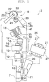
- the winding unit 2 includes an unwinding assisting device 10, a lower yarn blow-up section 11, a gate type tension applying device 12, an upper yarn catching section 13, a yarn joining device 14, a yarn trap 15, a cutter 16, a clearer (yarn defect detection device) 17, an upper yarn pull-out section 35, and the yarn storage device 18 arranged in this order from the bobbin supporting section 7 towards the winding section 8 on a yarn travelling path between the bobbin supporting section 7 and the winding section 8.
- the unwinding assisting device 10 causes a movable member 10a to make contact with a balloon formed at an upper part of the yarn supplying bobbin 21 when the yarn 20 unwound from the yarn supplying bobbin 21 is swung around, and controls the balloon to an appropriate size to assist the unwinding of the yarn 20.
- the lower yarn blow-up section 11 is an air sucker device arranged between the bobbin supporting section 7 and the yarn joining device 14, and is configured to feed a lower yarn from the yarn supplying bobbin 21 towards the yarn joining device 14 during the yarn joining operation.
- the gate type tension applying device 12 applies a predetermined tension to the travelling yarn 20.
- the gate type tension applying device 12 of the present embodiment is configured as a gate type in which movable comb teeth are arranged with respect to fixed comb teeth.
- the comb teeth on the movable side are configured to be swingable by a rotary solenoid so that the comb teeth can be in the meshed state or the released state.
- the configuration of the gate type tension applying device 12 is not limited thereto, and may be a disc type tension applying device, for example.
- the upper yarn catching section 13 is arranged between the yarn joining device 14 and the bobbin supporting section 7.
- the upper yarn catching section 13 is connected to a negative pressure source (not illustrated), and can generate a suction airflow during the yarn joining operation.
- the yarn trap 15 is arranged between the yarn joining device 14 and the yarn storage device 18.
- the distal end of the yarn trap 15 is formed as a tubular member and is arranged close to the travelling path of the yarn 20, and is connected to the negative pressure source (not illustrated). According to such a configuration, the suction airflow can be generated at the distal end of the yarn trap 15 to suck and remove contaminants such as fluffs attached to the travelling yarn 20.
- the clearer 17 is configured to detect the yarn defect such as slub by monitoring a yarn thickness of the yarn 20. When detecting the yarn defect, the clearer 17 transmits a disconnecting signal instructing the cutting and removal of the yarn defect to a control section 60 and the like. A cutter 16 for immediately cutting the yarn 20 according to the disconnecting signal is arranged in proximity to the clearer 17.
- the yarn joining device 14 joins the lower yarn from the yarn supplying bobbin 21, and the upper yarn from the yarn storage device 18, when the yarn 20 between the yarn supplying bobbin 21 and the package 30 is in the disconnected state after yarn breakage in which the clearer 17 detects the yarn defect and the cutter 16 cuts the yarn 20, after yarn breakage during unwinding of the yarn 20 from the yarn supplying bobbin 21, or at the time of replacing the yarn supplying bobbin 21.
- the yarn joining device 14 may be a type that uses a fluid such as compressed air, or may be a mechanical type.
- the upper yarn pull-out section 35 is an air sucker device, and pulls out the upper yarn from the yarn storage device 18 and feeds the upper yarn towards a deflection guide member 36.
- the upper yarn from the yarn storage device 18 is fed to the deflection guide member 36 by the upper yarn pull-out section 35.
- the deflection guide member 36 discharges the fed upper yarn from the lower end portion.
- the yarn discharged by the deflection guide member 36 is sucked by the upper yarn catching section 13.
- the upper yarn can be taken out from a slit (not illustrated) formed in the deflection guide member 36 as the upper yarn catching section 13 sucks the upper yarn, so that the upper yarn can be guided to the yarn joining device 14.
- the lower yarn fed by the lower yarn blow-up section 11 is sucked by the yarn trap 15.
- the lower yarn is thereby guided to the yarn joining device 14.
- the yarn joining operation is carried out in such a manner.
- the yarn defect is removed mainly by the clearer 17, the upper yarn catching section 13, the yarn trap 15, and the yarn joining device 14, and hence such devices correspond to "yarn defect removing device".
- the yarn storage device 18 is configured to be able to temporarily store the yarn 20 unwound from the yarn supplying bobbin 21. Since the yarn storage device 18 is interposed between the bobbin supporting section 7 and the winding section 8, and a prescribed amount of the yarn 20 is stored on the yarn storage device 18, the winding section 8 can wind the yarn 20 stored on the yarn storage device 18 even if the unwinding of the yarn from the yarn supplying bobbin 21 is interrupted (e.g., during yarn joining operation) for some reason. Thus, the winding of the yarn 20 into the package 30 can be continued.
- the package 30 can be produced stably at high speed. Furthermore, since the yarn 20 is not sucked and caught from the package 30 for each yarn joining operation as in the conventional yarn winding device, disturbance can be prevented from occurring at the surface of the package 30. Moreover, since the occurrence of yarn breakage in the winding section 8 is reduced, falling of the yarn 20 onto the end face of the package 30 or occurrence of a failure in the winding shape can be prevented.
- a first guide section 41, a second guide section 42, and a tension measuring device 43 are arranged on the downstream of the yarn storage device 18.
- the first guide section 41 converges the yarn 20 pulled out from the yarn storage device 18 so as to guide the yarn 20 to one area.
- the second guide section 42 is arranged downstream of the first guide section 41.
- the second guide section 42 forms a traverse supporting point of the yarn 20 to be wound in the winding section 8.
- the tension measuring device 43 is arranged between the first guide section 41 and the second guide section 42.
- the tension measuring device 43 is configured as a load cell type sensor. If the yarn 20 travels while being pushed against the contacting portion of the tension measuring device 43, distortion occurs in the load cell portion according to the tension of the yarn 20 and an electric signal corresponding to the distortion is output from a distortion gauge.
- a magazine type bobbin supplying device 26 is arranged on the front side of the winding unit 2.
- the bobbin supplying device 26 includes a rotary magazine part 27.
- the magazine part 27 is configured to be able to hold a plurality of spare yarn supplying bobbins 21.
- the bobbin supplying device 26 intermittently rotatably drives the magazine part 27 to supply a new yarn supplying bobbin 21 to the bobbin supporting section 7.
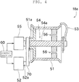
- the yarn storage device 18 includes a yarn storage roller 51, a roller driving section (first driving section) 52, a yarn hooking arm (tension applying section) 53, a transmission mechanism 54, and an arm driving section (second driving section) 55.
- the yarn storage roller 51 is formed as a substantially cylindrical member, and is configured to store the yarn 20 by winding the yarn 20 around the outer circumferential surface thereof.
- the roller driving section 52 rotatably drives the yarn storage roller 51 with a center axis line thereof as a center. Specifically, a belt 70 is wound around an output shaft 52a of the roller driving section 52 and a coupling member 51a fixed to the inner surface of the yarn storage roller 51, and the yarn storage roller 51 can be rotated by rotating the output shaft 52a.
- the operation of the roller driving section 52 is controlled by the control section 60.
- the roller driving section 52 is a servo motor, a stepping motor, or the like.
- the arm driving section 55 rotatably drives the yarn hooking arm 53 when the driving force is transmitted by the transmission mechanism 54.
- the transmission mechanism 54 of the present embodiment mainly includes a shaft 54a (yarn storage roller rotation shaft), and the shaft 54a transmits the driving force. According to such a configuration, the yarn hooking arm 53 can be rotatably driven around the same rotation axis as the yarn storage roller 51.
- the operation of the arm driving section 55 is controlled independently from the roller driving section 52 by the control section 60. Therefore, in the present embodiment, the rotation speeds of the yarn storage roller 51 and the yarn hooking arm 53 can be differed.
- the arm driving section 55 is a servo motor, a stepping motor, or the like.
- Each winding unit 2 includes the control section 60.
- the control section 60 is configured by hardware such as a CPU, a ROM, and a RAM (not illustrated), and software such as the control program stored in the RAM. The hardware and the software cooperatively operate to control each configuration of the winding unit 2.
- the control section 60 includes, as a configuration for controlling the arm driving section 55, a deviation calculating section 61, a PID control value determining section 62, and a limiter 63.
- the deviation calculating section 61 of the control section 60 is input with a tension measurement value measured by the tension measuring device 43. Furthermore, a tension target value derived from the winding conditions such as the type of yarn 20 and the yarn travelling speed is input to the deviation calculating section 61. The deviation calculating section 61 calculates the deviation of the two input values, and outputs the calculated deviation to the PID control value determining section 62.
- the PID control value determining section 62 calculates a control value for controlling the torque of the arm driving section 55 by a known PID control based on a deviation, time integral of the deviation, and time derivative of the deviation.
- the control value may be calculated based only on the deviation, and the control value may be calculated based only on the deviation and the time integral thereof.
- the feedback control other than the PID may be used.
- the PID control value determining section 62 outputs the control value calculated as above to the limiter 63.
- the limiter 63 defines an upper limit of the control value of the arm driving section 55.
- the limiter 63 outputs the relevant threshold to the arm driving section 55 as the control value.
- the limiter 63 outputs the input value as it is.
- the control value calculated as above is input to the arm driving section 55, and the torque of the arm driving section 55 is adjusted based on the control value.
- the control section 60 carries out the feedback control as necessary, so that even if the travelling speed of the yarn is high, the yarn hooking arm 53 can apply a desired tension to the yarn 20.
- the yarn winding device of the present embodiment includes the bobbin supporting section 7, the yarn storage roller 51, the winding section 8, the tension measuring device 43, the yarn hooking arm 53, the arm driving section 55, and the control section 60.
- the bobbin supporting section 7 can supply the yarn 20.
- the yarn storage roller 51 is rotatably driven by the roller driving section 52, so that the yarn 20 is pulled out from the yarn supplying bobbin 21 of the bobbin supporting section 7 and the yarn 20 is stored on the surface.
- the winding section 8 pulls out the yarn 20 stored on the yarn storage roller 51 to form the package 30.
- the tension measuring device 43 measures the tension of the yarn 20 pulled out from the yarn storage roller 51.
- the yarn hooking arm 53 is arranged downstream in the yarn travelling direction of the yarn storage roller 51, and makes contact with the yarn 20 to apply tension to the yarn 20.
- the arm driving section 55 rotatably drives the yarn hooking arm 53.
- the control section 60 feedback controls the arm driving section 55 based on the measurement result of the tension measuring device 43 to adjust the amount of tension applied by the yarn hooking arm 53.
- the yarn travelling direction of the yarn storage roller 51 in the present invention is a direction in which the yarn wound around the outer circumferential surface of the yarn storage roller 51 advances by being pushed by the newly wound yarn, and is the same direction as the axial direction of the shaft 54a.
- the tension on the downstream of the yarn storage roller 51 is measured, and the arm driving section 55 is controlled based on such a measurement result, the tension of the yarn 20 to be wound into the package 30 becomes the desired tension.
- the quality of the package 30 can be improved while the interruption of the winding of the yarn 20 is prevented.
- a yarn storage device 18a of the first alternative embodiment includes a resistance torque generating section 56.
- the resistance torque generating section 56 is a load such as a torque limiter attached between a shaft 54a and at least an inner surface of the yarn storage roller 51.
- the resistance torque generating section 56 thereby generates a torque against the relative rotation of the yarn storage roller 51 and the yarn hooking arm 53, and integrally rotates.
- the yarn hooking arm 53 can be relatively rotated with respect to the yarn storage roller 51 by driving the arm driving section 55 at greater than or equal to the above torque.
- the operation of the arm driving section 55 is stopped and the yarn storage roller 51 and the yarn hooking arm 53 are integrally rotated by the torque of the resistance torque generating section 56.
- the fluctuation of the tension is large, the fluctuation of the tension can be prevented by driving the arm driving section 55 and relatively rotating the yarn hooking arm 53.
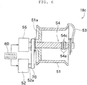
- a yarn storage device 18b of the second alternative embodiment includes the resistance torque generating section 56, similarly to the first alternative embodiment.
- the transmission mechanism 54 includes a clutch 54b in addition to the shaft 54a.
- the clutch 54b is a constituent element of the transmission mechanism 54.
- the clutch 54b switches the transmission or cutting of the driving force from the arm driving section 55 to the yarn hooking arm 53.
- the yarn storage roller 51 and the yarn hooking arm 53 can be integrally rotated without stopping the drive of the arm driving section 55 as in the first alternative embodiment. Therefore, for example, the yarn hooking arm 53 can be immediately decelerated by rotating the shaft 54a at a rotation speed slightly lower than the yarn storage roller 51 and connecting the clutch 54b when desiring to decelerate the yarn hooking arm 53.
- the transmission mechanism 54 of the yarn storage device 18c of the third alternative embodiment includes a torque limiter 54c in addition to the shaft 54a.
- the torque limiter 54c is attached to connect the shaft 54a divided in half.
- the two shafts 54a integrally rotate when a torque smaller than a predetermined value is applied by the torque limiter 54c, and the two shafts 54a relatively rotate when a torque greater than or equal to the predetermined value is applied.
- roller driving section 52 and the arm driving section 55 have at least one part arranged inside the yarn storage roller 51, but the roller driving section 52 and the arm driving section 55 may be arranged outside the yarn storage roller 51.
- the yarn hooking arm 53 may be arranged outside the yarn storage device 18.
- the tension measuring device 43 may be, for example, a tension sensor using a spring and/or a piezoelectric element, instead of a load cell type.
- control section 60 adjusts the torque of the arm driving section 55 based on the measured tension, but the position (rotation angle) and the speed (rotation speed) may be adjusted instead of the torque.
- the present invention may be applied to other yarn winding devices such as a spinning machine.
- a spinning section adapted to spin the spun yarn from the sliver corresponds to the yarn supplying section.
Landscapes
- Engineering & Computer Science (AREA)
- Textile Engineering (AREA)
- Mechanical Engineering (AREA)
- Tension Adjustment In Filamentary Materials (AREA)
- Filamentary Materials, Packages, And Safety Devices Therefor (AREA)
- Forwarding And Storing Of Filamentary Material (AREA)
Claims (7)
- Dispositif de bobinage de fil, comprenant:une section d'alimentation de fil (7) adaptée pour fournir un fil;un rouleau d'emmagasinage de fil (51) adapté pour sortir le fil de la section d'alimentation de fil (7) et enrouler le fil autour d'une surface circonférentielle extérieure pour emmagasiner le fil lorsque le rouleau d'emmagasinage de fil (51) est entraîné de manière rotative par une première section d'entraînement (52);une section de formation de paquet (8) adaptée pour sortir le fil emmagasiné sur le rouleau d'emmagasinage de fil (51) pour former un paquet;une section d'application de tension (53) arrangée en aval dans un sens de déplacement de fil du rouleau d'emmagasinage de fil (51) et adaptée pour entrer en contact avec le fil pour appliquer de la tension au fil;une deuxième section d'entraînement (55) adaptée pour entraîner de manière rotative la section d'application de tension (53); caractérisée par un dispositif de mesure de tension (43) adapté pour mesurer une tension du fil sorti du rouleau d'emmagasinage de fil (51) par la section de formation de paquet (8);etune section de contrôle (60) adaptée pour un contrôle rétroactif de la deuxième section d'entraînement (55) sur la base d'un résultat de mesure du dispositif de mesure de tension (43) pour ajuster un degré de tension appliquée par la section d'application de tension (53), où le rouleau d'emmagasinage de fil (51) tourne avec un arbre de rotation du rouleau d'emmagasinage de fil (54a) comme centre, etla section d'application de tension (53) tourne avec l'arbre de rotation du rouleau d'emmagasinage de fil (54a) comme centre, comprenant en outre:une section de génération de couple de résistance (56) adaptée pour générer un couple contre une rotation relative du rouleau d'emmagasinage de fil (51) et la section d'application de tension (53).
- Le dispositif de bobinage de fil selon la revendication 1,
caractérisé en comprenant en outre:une première section de guidage (41) arrangée en aval du rouleau d'emmagasinage de fil (51) et adaptée pour converger le fil sorti du rouleau d'emmagasinage de fil (51); etune deuxième section de guidage (42) arrangée en aval de la première section de guidage (41) et adaptée pour former un point de soutien transversal du fil enroulé par la section de formation de paquet (8), où le dispositif de mesure de tension (43) est arrangé sur une voie du fil entre la première section de guidage (41) et la deuxième section de guidage (42). - Le dispositif de bobinage de fil selon les revendications 1 ou 2,
caractérisé en ce que
la section de contrôle (60) ajuste le degré de tension appliquée par la section d'application de tension (53) en ajustant un couple de la deuxième section d'entraînement (55) sur la base d'un résultat de mesure du dispositif de mesure de tension (43). - Le dispositif de bobinage de fil selon la revendication 1,
caractérisé en comprenant en outre:un mécanisme de transmission (54) adapté pour transmettre une force d'entraînement de la deuxième section d'entraînement (55) à la section d'application de tension (53), oùle mécanisme de transmission (54) comprend un embrayage (54b) adapté pour changer la transmission ou arrêter la force d'entraînement de la deuxième section d'entraînement (55) à la section d'application de tension (53). - Le dispositif de bobinage de fil selon la revendication 1,
caractérisé en comprenant en outre:un mécanisme de transmission (54) adapté pour transmettre une force d'entraînement de la deuxième section d'entraînement (55) à la section d'application de tension (53), oùle mécanisme de transmission (54) comprend un limiteur de couple (54c) adapté pour empêcher qu'une force d'entraînement excessive est transmise de la deuxième section d'entraînement (55) à la section d'application de tension (53). - Le dispositif de bobinage de fil selon une des revendications 1 à 5,
caractérisé en ce que
la section d'alimentation de fil (7) est soutenue de sorte que le fil est fourni d'une bobine d'alimentation de fil, autour de laquelle le fil produit par un dispositif de filage est bobiné, et
un dispositif d'élimination de défaut de fil (13, 14, 15, 17) adapté pour éliminer un défaut de fil du fil fourni de la section d'alimentation de fil (7) est arrangé entre la section d'alimentation de fil (7) et le rouleau d'emmagasinage de fil (51). - Le dispositif de bobinage de fil selon une des revendications 1 à 6,
caractérisé en ce que
la section d'alimentation de fil (7) est une section de filage adaptée pour filer un fil, et
en ce qu'un dispositif d'élimination de défaut de fil (13, 14, 15, 17) adapté pour éliminer un défaut de fil du fil fourni de la section d'alimentation de fil (7) est arrangé entre la section d'alimentation de fil (7) et le rouleau d'emmagasinage de fil (51).
Applications Claiming Priority (1)
| Application Number | Priority Date | Filing Date | Title |
|---|---|---|---|
| JP2014136419A JP2016013892A (ja) | 2014-07-02 | 2014-07-02 | 糸巻取装置 |
Publications (2)
| Publication Number | Publication Date |
|---|---|
| EP2962973A1 EP2962973A1 (fr) | 2016-01-06 |
| EP2962973B1 true EP2962973B1 (fr) | 2017-07-05 |
Family
ID=53268710
Family Applications (1)
| Application Number | Title | Priority Date | Filing Date |
|---|---|---|---|
| EP15169247.2A Active EP2962973B1 (fr) | 2014-07-02 | 2015-05-26 | Dispositif de bobinage de fil |
Country Status (3)
| Country | Link |
|---|---|
| EP (1) | EP2962973B1 (fr) |
| JP (1) | JP2016013892A (fr) |
| CN (1) | CN105270922B (fr) |
Families Citing this family (4)
| Publication number | Priority date | Publication date | Assignee | Title |
|---|---|---|---|---|
| JP2019181841A (ja) * | 2018-04-12 | 2019-10-24 | 株式会社ミマキエンジニアリング | プリンタ |
| CN108425174B (zh) * | 2018-05-24 | 2023-09-01 | 浙江理工大学 | 一种恒张力携纱装置及其工作方法 |
| DE102018119164A1 (de) * | 2018-08-07 | 2020-02-13 | Maschinenfabrik Rieter Ag | Garnspeicher für eine Spinn- oder Spulmaschine |
| JP2020059599A (ja) * | 2018-10-12 | 2020-04-16 | 村田機械株式会社 | 糸巻取装置及び糸巻取方法 |
Family Cites Families (11)
| Publication number | Priority date | Publication date | Assignee | Title |
|---|---|---|---|---|
| CA1124818A (fr) * | 1978-10-18 | 1982-06-01 | Charles W. Brouwer | Amelioration sur ensouples de tissage |
| JP2806899B2 (ja) * | 1995-11-17 | 1998-09-30 | 日特エンジニアリング株式会社 | 線条材の巻取装置 |
| EP1457447B1 (fr) * | 2003-03-13 | 2012-06-06 | Murata Kikai Kabushiki Kaisha | Dispositif de réglage de tension et d'élimination des relâchements de fil pour un dispositif de bobinage |
| DE602004001410T2 (de) * | 2003-03-17 | 2007-07-05 | Murata Kikai K.K. | Spulmaschine für Faden |
| JP2008105755A (ja) * | 2006-10-23 | 2008-05-08 | Murata Mach Ltd | 電磁式テンサーを組み込んだ糸弛み取り装置 |
| JP2009046778A (ja) * | 2007-08-21 | 2009-03-05 | Murata Mach Ltd | 巻取テンション制御装置 |
| JP2010077576A (ja) * | 2008-09-29 | 2010-04-08 | Murata Machinery Ltd | 紡績機 |
| JP5884280B2 (ja) * | 2011-03-18 | 2016-03-15 | 村田機械株式会社 | 糸巻取装置及び糸巻取方法 |
| JP2013063839A (ja) * | 2011-09-20 | 2013-04-11 | Murata Machinery Ltd | 糸巻取機及び糸巻取ユニット |
| CZ303880B6 (cs) | 2012-07-12 | 2013-06-05 | Rieter Cz S.R.O. | Bubnový mezizásobník príze na pracovním míste textilního stroje a zpusob jeho rízení |
| CN203451716U (zh) * | 2013-07-27 | 2014-02-26 | 陕西华燕航空仪表有限公司 | 纱线张力恒定装置 |
-
2014
- 2014-07-02 JP JP2014136419A patent/JP2016013892A/ja active Pending
-
2015
- 2015-05-26 EP EP15169247.2A patent/EP2962973B1/fr active Active
- 2015-06-17 CN CN201510337479.2A patent/CN105270922B/zh active Active
Non-Patent Citations (1)
| Title |
|---|
| None * |
Also Published As
| Publication number | Publication date |
|---|---|
| EP2962973A1 (fr) | 2016-01-06 |
| CN105270922A (zh) | 2016-01-27 |
| JP2016013892A (ja) | 2016-01-28 |
| CN105270922B (zh) | 2019-06-07 |
Similar Documents
| Publication | Publication Date | Title |
|---|---|---|
| EP2998254B1 (fr) | Dispositif de renvideur de fil et procédé de renvidage de fil | |
| EP2169096B1 (fr) | Fileuse | |
| US8931249B2 (en) | Spinning machine and method for interrupting yarn production on a spinning machine | |
| EP2202192B1 (fr) | Dispositif de bobinage de fil et enrouleur automatique | |
| EP2216432B2 (fr) | Procédé de traitement de fils et fileuse | |
| US8919091B2 (en) | Spinning machine and method for interrupting yarn production on a spinning machine | |
| EP2962973B1 (fr) | Dispositif de bobinage de fil | |
| EP3009387B1 (fr) | Boîtier de dispositif de bobinage de fil et procédé de décélération de paquet | |
| EP2808283B1 (fr) | Renvideur de fil | |
| EP2159180B1 (fr) | Dispositif de bobinage de fil et enrouleur automatique | |
| EP2573217B1 (fr) | Unité de filage, métier à filer et procédé de traitement de fil | |
| EP2738129B1 (fr) | Machine de bobinage de fil et machine textile la comprenant | |
| EP2990367B1 (fr) | Dispositif de bobinage de fil | |
| EP2573224B1 (fr) | Unité de filage et dispositif de filage | |
| JP2016016957A (ja) | 糸巻取機及び糸巻取方法 | |
| EP3000756B1 (fr) | Dispositif de bobinage de fil et machine textile | |
| EP2960196B1 (fr) | Machine de renvideur de fil | |
| EP2738128B1 (fr) | Machine de renvideur de fil | |
| WO2020075444A1 (fr) | Dispositif d'enroulement de fil et procédé d'enroulement de fil | |
| CN111683888B (zh) | 纱线卷取机以及纱线卷取方法 | |
| CN111132918B (zh) | 纱线卷取机 | |
| CN112110288A (zh) | 纱线卷取装置以及自动络纱机 | |
| CN115924627A (zh) | 交叉卷绕卷装、交叉卷绕卷装的制造方法及纱线卷取装置 | |
| CN113979220A (zh) | 纱线卷取机以及卷取异常检测方法 |
Legal Events
| Date | Code | Title | Description |
|---|---|---|---|
| PUAI | Public reference made under article 153(3) epc to a published international application that has entered the european phase |
Free format text: ORIGINAL CODE: 0009012 |
|
| AK | Designated contracting states |
Kind code of ref document: A1 Designated state(s): AL AT BE BG CH CY CZ DE DK EE ES FI FR GB GR HR HU IE IS IT LI LT LU LV MC MK MT NL NO PL PT RO RS SE SI SK SM TR |
|
| AX | Request for extension of the european patent |
Extension state: BA ME |
|
| 17P | Request for examination filed |
Effective date: 20160216 |
|
| RBV | Designated contracting states (corrected) |
Designated state(s): AL AT BE BG CH CY CZ DE DK EE ES FI FR GB GR HR HU IE IS IT LI LT LU LV MC MK MT NL NO PL PT RO RS SE SI SK SM TR |
|
| 17Q | First examination report despatched |
Effective date: 20160929 |
|
| GRAP | Despatch of communication of intention to grant a patent |
Free format text: ORIGINAL CODE: EPIDOSNIGR1 |
|
| INTG | Intention to grant announced |
Effective date: 20170216 |
|
| GRAS | Grant fee paid |
Free format text: ORIGINAL CODE: EPIDOSNIGR3 |
|
| GRAA | (expected) grant |
Free format text: ORIGINAL CODE: 0009210 |
|
| AK | Designated contracting states |
Kind code of ref document: B1 Designated state(s): AL AT BE BG CH CY CZ DE DK EE ES FI FR GB GR HR HU IE IS IT LI LT LU LV MC MK MT NL NO PL PT RO RS SE SI SK SM TR |
|
| REG | Reference to a national code |
Ref country code: GB Ref legal event code: FG4D |
|
| REG | Reference to a national code |
Ref country code: CH Ref legal event code: EP Ref country code: CH Ref legal event code: NV Representative=s name: ING. ALESSANDRO GALASSI C/O PGA S.P.A., MILANO, CH |
|
| REG | Reference to a national code |
Ref country code: AT Ref legal event code: REF Ref document number: 906449 Country of ref document: AT Kind code of ref document: T Effective date: 20170715 |
|
| REG | Reference to a national code |
Ref country code: IE Ref legal event code: FG4D |
|
| REG | Reference to a national code |
Ref country code: DE Ref legal event code: R096 Ref document number: 602015003394 Country of ref document: DE |
|
| REG | Reference to a national code |
Ref country code: NL Ref legal event code: MP Effective date: 20170705 |
|
| REG | Reference to a national code |
Ref country code: AT Ref legal event code: MK05 Ref document number: 906449 Country of ref document: AT Kind code of ref document: T Effective date: 20170705 |
|
| REG | Reference to a national code |
Ref country code: LT Ref legal event code: MG4D |
|
| PG25 | Lapsed in a contracting state [announced via postgrant information from national office to epo] |
Ref country code: NO Free format text: LAPSE BECAUSE OF FAILURE TO SUBMIT A TRANSLATION OF THE DESCRIPTION OR TO PAY THE FEE WITHIN THE PRESCRIBED TIME-LIMIT Effective date: 20171005 Ref country code: AT Free format text: LAPSE BECAUSE OF FAILURE TO SUBMIT A TRANSLATION OF THE DESCRIPTION OR TO PAY THE FEE WITHIN THE PRESCRIBED TIME-LIMIT Effective date: 20170705 Ref country code: FI Free format text: LAPSE BECAUSE OF FAILURE TO SUBMIT A TRANSLATION OF THE DESCRIPTION OR TO PAY THE FEE WITHIN THE PRESCRIBED TIME-LIMIT Effective date: 20170705 Ref country code: SE Free format text: LAPSE BECAUSE OF FAILURE TO SUBMIT A TRANSLATION OF THE DESCRIPTION OR TO PAY THE FEE WITHIN THE PRESCRIBED TIME-LIMIT Effective date: 20170705 Ref country code: NL Free format text: LAPSE BECAUSE OF FAILURE TO SUBMIT A TRANSLATION OF THE DESCRIPTION OR TO PAY THE FEE WITHIN THE PRESCRIBED TIME-LIMIT Effective date: 20170705 Ref country code: LT Free format text: LAPSE BECAUSE OF FAILURE TO SUBMIT A TRANSLATION OF THE DESCRIPTION OR TO PAY THE FEE WITHIN THE PRESCRIBED TIME-LIMIT Effective date: 20170705 Ref country code: HR Free format text: LAPSE BECAUSE OF FAILURE TO SUBMIT A TRANSLATION OF THE DESCRIPTION OR TO PAY THE FEE WITHIN THE PRESCRIBED TIME-LIMIT Effective date: 20170705 |
|
| PG25 | Lapsed in a contracting state [announced via postgrant information from national office to epo] |
Ref country code: IS Free format text: LAPSE BECAUSE OF FAILURE TO SUBMIT A TRANSLATION OF THE DESCRIPTION OR TO PAY THE FEE WITHIN THE PRESCRIBED TIME-LIMIT Effective date: 20171105 Ref country code: PL Free format text: LAPSE BECAUSE OF FAILURE TO SUBMIT A TRANSLATION OF THE DESCRIPTION OR TO PAY THE FEE WITHIN THE PRESCRIBED TIME-LIMIT Effective date: 20170705 Ref country code: LV Free format text: LAPSE BECAUSE OF FAILURE TO SUBMIT A TRANSLATION OF THE DESCRIPTION OR TO PAY THE FEE WITHIN THE PRESCRIBED TIME-LIMIT Effective date: 20170705 Ref country code: ES Free format text: LAPSE BECAUSE OF FAILURE TO SUBMIT A TRANSLATION OF THE DESCRIPTION OR TO PAY THE FEE WITHIN THE PRESCRIBED TIME-LIMIT Effective date: 20170705 Ref country code: GR Free format text: LAPSE BECAUSE OF FAILURE TO SUBMIT A TRANSLATION OF THE DESCRIPTION OR TO PAY THE FEE WITHIN THE PRESCRIBED TIME-LIMIT Effective date: 20171006 Ref country code: RS Free format text: LAPSE BECAUSE OF FAILURE TO SUBMIT A TRANSLATION OF THE DESCRIPTION OR TO PAY THE FEE WITHIN THE PRESCRIBED TIME-LIMIT Effective date: 20170705 Ref country code: BG Free format text: LAPSE BECAUSE OF FAILURE TO SUBMIT A TRANSLATION OF THE DESCRIPTION OR TO PAY THE FEE WITHIN THE PRESCRIBED TIME-LIMIT Effective date: 20171005 |
|
| REG | Reference to a national code |
Ref country code: DE Ref legal event code: R097 Ref document number: 602015003394 Country of ref document: DE |
|
| PG25 | Lapsed in a contracting state [announced via postgrant information from national office to epo] |
Ref country code: RO Free format text: LAPSE BECAUSE OF FAILURE TO SUBMIT A TRANSLATION OF THE DESCRIPTION OR TO PAY THE FEE WITHIN THE PRESCRIBED TIME-LIMIT Effective date: 20170705 Ref country code: DK Free format text: LAPSE BECAUSE OF FAILURE TO SUBMIT A TRANSLATION OF THE DESCRIPTION OR TO PAY THE FEE WITHIN THE PRESCRIBED TIME-LIMIT Effective date: 20170705 |
|
| PLBE | No opposition filed within time limit |
Free format text: ORIGINAL CODE: 0009261 |
|
| STAA | Information on the status of an ep patent application or granted ep patent |
Free format text: STATUS: NO OPPOSITION FILED WITHIN TIME LIMIT |
|
| PG25 | Lapsed in a contracting state [announced via postgrant information from national office to epo] |
Ref country code: SM Free format text: LAPSE BECAUSE OF FAILURE TO SUBMIT A TRANSLATION OF THE DESCRIPTION OR TO PAY THE FEE WITHIN THE PRESCRIBED TIME-LIMIT Effective date: 20170705 Ref country code: SK Free format text: LAPSE BECAUSE OF FAILURE TO SUBMIT A TRANSLATION OF THE DESCRIPTION OR TO PAY THE FEE WITHIN THE PRESCRIBED TIME-LIMIT Effective date: 20170705 Ref country code: EE Free format text: LAPSE BECAUSE OF FAILURE TO SUBMIT A TRANSLATION OF THE DESCRIPTION OR TO PAY THE FEE WITHIN THE PRESCRIBED TIME-LIMIT Effective date: 20170705 |
|
| 26N | No opposition filed |
Effective date: 20180406 |
|
| PG25 | Lapsed in a contracting state [announced via postgrant information from national office to epo] |
Ref country code: SI Free format text: LAPSE BECAUSE OF FAILURE TO SUBMIT A TRANSLATION OF THE DESCRIPTION OR TO PAY THE FEE WITHIN THE PRESCRIBED TIME-LIMIT Effective date: 20170705 |
|
| REG | Reference to a national code |
Ref country code: BE Ref legal event code: MM Effective date: 20180531 |
|
| PG25 | Lapsed in a contracting state [announced via postgrant information from national office to epo] |
Ref country code: MC Free format text: LAPSE BECAUSE OF FAILURE TO SUBMIT A TRANSLATION OF THE DESCRIPTION OR TO PAY THE FEE WITHIN THE PRESCRIBED TIME-LIMIT Effective date: 20170705 |
|
| REG | Reference to a national code |
Ref country code: IE Ref legal event code: MM4A |
|
| PG25 | Lapsed in a contracting state [announced via postgrant information from national office to epo] |
Ref country code: LU Free format text: LAPSE BECAUSE OF NON-PAYMENT OF DUE FEES Effective date: 20180526 |
|
| PG25 | Lapsed in a contracting state [announced via postgrant information from national office to epo] |
Ref country code: FR Free format text: LAPSE BECAUSE OF NON-PAYMENT OF DUE FEES Effective date: 20180531 Ref country code: IE Free format text: LAPSE BECAUSE OF NON-PAYMENT OF DUE FEES Effective date: 20180526 |
|
| PG25 | Lapsed in a contracting state [announced via postgrant information from national office to epo] |
Ref country code: BE Free format text: LAPSE BECAUSE OF NON-PAYMENT OF DUE FEES Effective date: 20180531 |
|
| GBPC | Gb: european patent ceased through non-payment of renewal fee |
Effective date: 20190526 |
|
| PG25 | Lapsed in a contracting state [announced via postgrant information from national office to epo] |
Ref country code: MT Free format text: LAPSE BECAUSE OF NON-PAYMENT OF DUE FEES Effective date: 20180526 |
|
| PG25 | Lapsed in a contracting state [announced via postgrant information from national office to epo] |
Ref country code: TR Free format text: LAPSE BECAUSE OF FAILURE TO SUBMIT A TRANSLATION OF THE DESCRIPTION OR TO PAY THE FEE WITHIN THE PRESCRIBED TIME-LIMIT Effective date: 20170705 |
|
| PG25 | Lapsed in a contracting state [announced via postgrant information from national office to epo] |
Ref country code: GB Free format text: LAPSE BECAUSE OF NON-PAYMENT OF DUE FEES Effective date: 20190526 |
|
| PG25 | Lapsed in a contracting state [announced via postgrant information from national office to epo] |
Ref country code: PT Free format text: LAPSE BECAUSE OF FAILURE TO SUBMIT A TRANSLATION OF THE DESCRIPTION OR TO PAY THE FEE WITHIN THE PRESCRIBED TIME-LIMIT Effective date: 20170705 |
|
| PG25 | Lapsed in a contracting state [announced via postgrant information from national office to epo] |
Ref country code: MK Free format text: LAPSE BECAUSE OF NON-PAYMENT OF DUE FEES Effective date: 20170705 Ref country code: HU Free format text: LAPSE BECAUSE OF FAILURE TO SUBMIT A TRANSLATION OF THE DESCRIPTION OR TO PAY THE FEE WITHIN THE PRESCRIBED TIME-LIMIT; INVALID AB INITIO Effective date: 20150526 Ref country code: CY Free format text: LAPSE BECAUSE OF FAILURE TO SUBMIT A TRANSLATION OF THE DESCRIPTION OR TO PAY THE FEE WITHIN THE PRESCRIBED TIME-LIMIT Effective date: 20170705 |
|
| PG25 | Lapsed in a contracting state [announced via postgrant information from national office to epo] |
Ref country code: AL Free format text: LAPSE BECAUSE OF FAILURE TO SUBMIT A TRANSLATION OF THE DESCRIPTION OR TO PAY THE FEE WITHIN THE PRESCRIBED TIME-LIMIT Effective date: 20170705 |
|
| PGFP | Annual fee paid to national office [announced via postgrant information from national office to epo] |
Ref country code: DE Payment date: 20240418 Year of fee payment: 10 |
|
| PGFP | Annual fee paid to national office [announced via postgrant information from national office to epo] |
Ref country code: CH Payment date: 20240602 Year of fee payment: 10 |
|
| PGFP | Annual fee paid to national office [announced via postgrant information from national office to epo] |
Ref country code: CZ Payment date: 20240423 Year of fee payment: 10 |
|
| PGFP | Annual fee paid to national office [announced via postgrant information from national office to epo] |
Ref country code: IT Payment date: 20240418 Year of fee payment: 10 |