EP2962941A1 - System for displaying dynamic visual stimuli on a runway - Google Patents
System for displaying dynamic visual stimuli on a runway Download PDFInfo
- Publication number
- EP2962941A1 EP2962941A1 EP14175059.6A EP14175059A EP2962941A1 EP 2962941 A1 EP2962941 A1 EP 2962941A1 EP 14175059 A EP14175059 A EP 14175059A EP 2962941 A1 EP2962941 A1 EP 2962941A1
- Authority
- EP
- European Patent Office
- Prior art keywords
- aircraft
- airport
- runway
- lights
- central processing
- Prior art date
- Legal status (The legal status is an assumption and is not a legal conclusion. Google has not performed a legal analysis and makes no representation as to the accuracy of the status listed.)
- Granted
Links
- 230000000007 visual effect Effects 0.000 title claims abstract description 23
- 238000005286 illumination Methods 0.000 claims description 9
- 238000000034 method Methods 0.000 claims description 6
- XLYOFNOQVPJJNP-UHFFFAOYSA-N water Substances O XLYOFNOQVPJJNP-UHFFFAOYSA-N 0.000 claims description 2
- 230000000295 complement effect Effects 0.000 abstract description 3
- 239000003086 colorant Substances 0.000 description 2
- 239000000446 fuel Substances 0.000 description 1
Images



Classifications
-
- B—PERFORMING OPERATIONS; TRANSPORTING
- B64—AIRCRAFT; AVIATION; COSMONAUTICS
- B64F—GROUND OR AIRCRAFT-CARRIER-DECK INSTALLATIONS SPECIALLY ADAPTED FOR USE IN CONNECTION WITH AIRCRAFT; DESIGNING, MANUFACTURING, ASSEMBLING, CLEANING, MAINTAINING OR REPAIRING AIRCRAFT, NOT OTHERWISE PROVIDED FOR; HANDLING, TRANSPORTING, TESTING OR INSPECTING AIRCRAFT COMPONENTS, NOT OTHERWISE PROVIDED FOR
- B64F1/00—Ground or aircraft-carrier-deck installations
- B64F1/18—Visual or acoustic landing aids
- B64F1/20—Arrangement of optical beacons
- B64F1/205—Arrangement of optical beacons arranged underground, e.g. underground runway lighting units
-
- B—PERFORMING OPERATIONS; TRANSPORTING
- B64—AIRCRAFT; AVIATION; COSMONAUTICS
- B64D—EQUIPMENT FOR FITTING IN OR TO AIRCRAFT; FLIGHT SUITS; PARACHUTES; ARRANGEMENT OR MOUNTING OF POWER PLANTS OR PROPULSION TRANSMISSIONS IN AIRCRAFT
- B64D45/00—Aircraft indicators or protectors not otherwise provided for
- B64D45/04—Landing aids; Safety measures to prevent collision with earth's surface
- B64D45/08—Landing aids; Safety measures to prevent collision with earth's surface optical
Definitions
- This invention relates to a system for displaying, on an airport runway, dynamic visual stimuli specific to an aircraft before and during its take-off or landing operation in order to complement the information provided visually to the flight crew of said aircraft.
- the common location on which those operations occur is the runway and during these above mentioned operations, the pilots have to constantly watch the environment of the runway and track their flight instruments, thus increasing fatigue and stress and reducing their concentration.
- the ALS is a lighting system installed on the approach end of an airport runway and consisting of a series of lightbars, strobe lights, or a combination of the two that extends outward from the runway end. ALS allows the pilot to visually identify the runway environment and align the aircraft with the runway upon arriving at a prescribed point on an approach.
- the ALS is controlled by the air traffic control tower depending on the position of the aircraft relative to the runway given by radio signals.
- the ALS does not take into account flight parameters such as the fuel quantity, speed, weight, type of aircraft and characteristics of the aircraft... of the aircraft that is landing.
- the visual information it gives is merely indicative and does not allow the pilots to reduce the back and forth between the outside environment and the flight panel.
- a system for displaying dynamic visual stimuli to a flight crew of an aircraft using a plurality of lights located on an airport comprising a module on-board the aircraft and, located on the airport, a central processing unit and a transceiver, the module comprising a transmitter for sending flight parameters to the central processing unit via the transceiver, said central processing unit being configured for controlling the lights at least depending on the received flight parameters from the aircraft so as to display a predetermined illuminating pattern on the airport to said flight crew before or during take-off or landing operation.
- the invention concerns also a method for displaying dynamic visual stimuli to a flight crew of an aircraft on an airport using a plurality of lights, said lights being controlled by a central processing unit located on the airport, the method comprising:
- One advantage of the present invention is that dynamic lighting adapting to the flight parameters of the aircraft is provided on the airport in order to complement the information provided to the flight crew during the take-off and/or landing operation by dynamically displaying markers and symbols on the airport so that the pilots can reduce the visual back and forth between the outside environment and their flight instruments.
- the shape of the markers and the symbols adapts in real time based on the data received from the aircraft in order to provide a higher level of situational awareness to the flight crew, thus increasing safety.
- FIG. 1 there is shown a system for displaying dynamic visual stimuli on the runway surface 2 of an airport comprising a module 3 on-board an aircraft 4 and a segment 5 located on the ground (airport).
- the module 3 on-board the aircraft designated thereafter on-board module, comprises an avionics application 10 and a transmitter 11 for sending data to the ground.
- the avionics application is, for example, hosted in a LRU (Line replaceable unit) arranged in the avionics bay of the aircraft 4.
- the avionics is configured to, when executed, establish a data link with the segment 5 located on the ground through the transmitter 11 so as to send flight parameters from the aircraft to the ground.
- Said flight parameters from the aircraft are provided to the avionics application by the avionics systems 12 of the aircraft, for instance the flight management system (FMS) and comprise at least the speed of the aircraft, the weight of the aircraft, its altitude, the current operation (take-off, landing of the aircraft).
- the flight parameters also comprises the status of the flight controls surfaces of the aircraft (angle of the flaps, angle of the rudder, angle of the elevator, angle of the ailerons, deployment of the spoilers,).
- the transmitter 11 is of the type of the data link systems commonly available on the aircrafts, such as a VHF data link, a HF data link, a SATCOM data link, Wi-Fi channel, etc...
- the segment 5 located on the airport comprises a transceiver 20 for receiving the flight parameters from the on-board module 3, a plurality of lights 21 arranged on the runway and a central processing unit 22.
- the transceiver 20 is compatible with the transmitter 11 and is of the type of the data link systems commonly available on the airports for exchanging data with aircrafts, such as a VHF data link, a HF data link, a SATCOM data link, Wi-Fi channel, etc...
- the central processing unit 22 receives flight parameters from the transmitter 11 through the transceiver 20 and, The central processing unique treats this performance calculations to compute the coordinates on the runway surface at which the different take-off or landing (depending on the flight phase of the aircraft) constraints will occur (for instance V1, touch down, full stop ). Then, depending on the computed coordinates, the central processing controls the lights 21 according to instructions saved in a memory of the central processing unit 22. In the present specification, "controlling the lights” mean switching on/off the lights and/or changing their colour and/or changing their illumination.
- the central processing unit 22 controls the lights 21 by sending control signals to them for displaying a least one visual stimulus on the surface of the runway.
- Each visual stimulus corresponds to a predetermined illumination pattern chosen among a plurality of predetermined illumination patterns with each pattern being associated with at least a take-off/landing constraint and the coordinates on the runway surface (2) at which said constraint will occur.
- the plurality of predetermined illumination patterns is saved in a first database hosted in a memory of the central processing unit 22.
- the predetermined illumination patterns are conceived such that they represents markers and symbols that are explicit for a flight crew as it will be explained below through different examples of flight operations.
- the lights 21 are embedded on the surface of the runway 2.
- the lights are preferably arranged in an array that extends over the whole length of the runway.
- the lights 21 are for example light-emitting diodes of various colours so as to display symbols and markers in different colours to quickly inform the flight crew of the status of an operation: green when the operations are normal, red when there is a danger.
- the system according to the invention is, for example, used during a take-off operation of an aircraft to signal to the flight crew the exact point in the runway where the V1 speed is expected to be achieved once the aircraft has started its run.
- the on-board module 3 continuously transmits flight parameters from the aircraft 4 to central processing unit 22 5 which, this way, receives constant information for computing the coordinates on the runway at which the V1 speed will be reached by the aircraft 4.
- the central processing unit 22 controls the lights 21 to display forward facing arrows 30, leading to a line 31 which indicates the V1 point.
- the central processing unit 22 automatically adjusts the position of the line 31 according to values of the flight parameters transmitted by the on-board module 3.
- the central processing unit 22 controls the lights 21 to display red crosses 32 on the remaining surface of the runway as it is illustrated at Fig.3 . This will inform the flight crew that the runway 2 is no longer usable and that the aircraft 4 must become airborne.
- the system according to the invention is for example used during a landing operation of an aircraft 4.
- the avionics application 10 initiates the data link exchanges between the on-board module 3 and the on-ground segment 5 during the final approach once the aircraft has reached a threshold altitude above the runway (e.g. 1500 feet).
- the central processing unit 22 commands the lights 21 for displaying backward facing arrows 40, starting at a first line 41 which depicts the calculate touchdown point and ending in a second line 42 which depicts the point, called safety point, where it is calculated that the speed of the aircraft 4 will be low enough to vacate the runway.
- the central processing unit 22 When the central processing unit 22 computes the coordinates of the safety point farther away from the touchdown point than the computed available distance on the runway, the central processing unit 22 changes the appearance of all symbols and markers on the runway surface to red crosses 50 (as illustrated at Fig.5 ), thus indicating to the flight crew that the runway 2 should not be used.
- the on-ground segment 5 is remotely coupled in real time to the information from the aircraft systems so as to display symbols and markers 30-32, 40-43, 50 on the runway 2.
- dynamic visual stimuli are displayed on the runway 2 to reinforce certain constraints and to provide additional references to the flight crews in order to increase safety.
- the central processing unit 22 controls the lights 21 depending also on data relative to the status of the runway 2.
- Data relative to the status of the runway 2 comprises parameters, hereinafter referred to as extra parameters, provided by ground-based sensors (not illustrated) connected to the central processing unit 22 and whose values have a direct impact on the performance of the aircraft 4 on the ground.
- extra parameters are for example the rate of humidity at the ground level, the height of a water layer on the runway 2, the direction and speed of the wind at the ground level...
- the central processing unit 22 receives the values of the extra parameters as input parameters in addition to the flight parameters from the aircraft and adjusts, according to computation rules saved in a memory, the computed coordinates on the runway surface at which a take-off or landing constraint of the aircraft will occur by taking into account the values of the extra parameters.
- This second embodiment allows displaying stimuli on the runway 2 that are specific to both the aircraft 4 performances and the status of the runway 2.
- the lights 21 are consisting of a series of light bars, strobe lights, or a combination of the two that extends outward from the runway end and/or that extends on the sides of the runway. In a further embodiment, the lights 21 are located on a dedicated area on the airport that is close to the runway.
Landscapes
- Engineering & Computer Science (AREA)
- Aviation & Aerospace Engineering (AREA)
- Physics & Mathematics (AREA)
- Acoustics & Sound (AREA)
- Mechanical Engineering (AREA)
- Traffic Control Systems (AREA)
- Road Paving Structures (AREA)
Abstract
Description
- This invention relates to a system for displaying, on an airport runway, dynamic visual stimuli specific to an aircraft before and during its take-off or landing operation in order to complement the information provided visually to the flight crew of said aircraft.
- On-ground operations, and in particular take-off and landing, are stressful for the flight crews due to the required precision of the control inputs and the fact that a long sequence of actions and decisions have to be performed in a very short period of time by the crew. The common location on which those operations occur is the runway and during these above mentioned operations, the pilots have to constantly watch the environment of the runway and track their flight instruments, thus increasing fatigue and stress and reducing their concentration.
- Therefore, there is a need for a visual system that could provide flight guidance to pilots so that they can reduce the visual back and forth between the outside environment and their flight instruments.
- Current visual systems exist such as the approach lighting system (ALS) that helps the pilots during landing. The ALS is a lighting system installed on the approach end of an airport runway and consisting of a series of lightbars, strobe lights, or a combination of the two that extends outward from the runway end. ALS allows the pilot to visually identify the runway environment and align the aircraft with the runway upon arriving at a prescribed point on an approach. The ALS is controlled by the air traffic control tower depending on the position of the aircraft relative to the runway given by radio signals.
- Although very useful, the ALS does not take into account flight parameters such as the fuel quantity, speed, weight, type of aircraft and characteristics of the aircraft... of the aircraft that is landing. Hence, the visual information it gives is merely indicative and does not allow the pilots to reduce the back and forth between the outside environment and the flight panel.
- It is an object of this invention to provide a visual system which at least partially meets the mentioned need. According to the invention, there is provided a system for displaying dynamic visual stimuli to a flight crew of an aircraft using a plurality of lights located on an airport, the system comprising a module on-board the aircraft and, located on the airport, a central processing unit and a transceiver, the module comprising a transmitter for sending flight parameters to the central processing unit via the transceiver, said central processing unit being configured for controlling the lights at least depending on the received flight parameters from the aircraft so as to display a predetermined illuminating pattern on the airport to said flight crew before or during take-off or landing operation.
- The invention concerns also a method for displaying dynamic visual stimuli to a flight crew of an aircraft on an airport using a plurality of lights, said lights being controlled by a central processing unit located on the airport, the method comprising:
- Establishing a data link between the central processing unit and a module on-board an aircraft which is either taking off from a runway or landing on a runway of the airport;
- Sending flight parameters from said aircraft to the central processing unit;
- Controlling the lights (depending on the received flight parameters so as to display a predetermined illuminating pattern on the airport to said flight crew.
- One advantage of the present invention is that dynamic lighting adapting to the flight parameters of the aircraft is provided on the airport in order to complement the information provided to the flight crew during the take-off and/or landing operation by dynamically displaying markers and symbols on the airport so that the pilots can reduce the visual back and forth between the outside environment and their flight instruments. The shape of the markers and the symbols adapts in real time based on the data received from the aircraft in order to provide a higher level of situational awareness to the flight crew, thus increasing safety.
- The invention will now be described by way of example with reference to the accompanying drawings of which:
-
Fig.1 is a schematic representation of a system according to a first embodiment of the invention for displaying dynamic visual stimuli on an airport surface to a flight crew; -
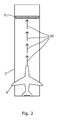
Fig.2 is a schematic representation of the visual stimuli displayed by the system of theFig.1 prior to an aircraft reaches a V1 speed during a take-off operation; -
Fig.3 is a schematic representation of the visual stimuli displayed by the system of theFig.1 after the aircraft has reached the V1 speed during a take-off operation; -
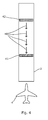
Fig.4 is a schematic representation of the visual stimuli displayed by the system of theFig.1 during a final approach of an aircraft during a landing operation; and -
Fig. 5 is a schematic representation of the visual stimuli displayed by the system of theFig.1 during a landing operation when a potential overrun is detected. - With reference to
FIG. 1 , there is shown a system for displaying dynamic visual stimuli on therunway surface 2 of an airport comprising amodule 3 on-board anaircraft 4 and asegment 5 located on the ground (airport). - The
module 3 on-board the aircraft, designated thereafter on-board module, comprises anavionics application 10 and atransmitter 11 for sending data to the ground. The avionics application is, for example, hosted in a LRU (Line replaceable unit) arranged in the avionics bay of theaircraft 4. The avionics is configured to, when executed, establish a data link with thesegment 5 located on the ground through thetransmitter 11 so as to send flight parameters from the aircraft to the ground. Said flight parameters from the aircraft are provided to the avionics application by theavionics systems 12 of the aircraft, for instance the flight management system (FMS) and comprise at least the speed of the aircraft, the weight of the aircraft, its altitude, the current operation (take-off, landing of the aircraft). Preferably, the flight parameters also comprises the status of the flight controls surfaces of the aircraft (angle of the flaps, angle of the rudder, angle of the elevator, angle of the ailerons, deployment of the spoilers,...). - The
transmitter 11 is of the type of the data link systems commonly available on the aircrafts, such as a VHF data link, a HF data link, a SATCOM data link, Wi-Fi channel, etc... - The
segment 5 located on the airport, called on-ground segment, comprises atransceiver 20 for receiving the flight parameters from the on-board module 3, a plurality oflights 21 arranged on the runway and acentral processing unit 22. - The
transceiver 20 is compatible with thetransmitter 11 and is of the type of the data link systems commonly available on the airports for exchanging data with aircrafts, such as a VHF data link, a HF data link, a SATCOM data link, Wi-Fi channel, etc... - The
central processing unit 22 receives flight parameters from thetransmitter 11 through thetransceiver 20 and, The central processing unique treats this performance calculations to compute the coordinates on the runway surface at which the different take-off or landing (depending on the flight phase of the aircraft) constraints will occur ( for instance V1, touch down, full stop ...). Then, depending on the computed coordinates, the central processing controls thelights 21 according to instructions saved in a memory of thecentral processing unit 22. In the present specification, "controlling the lights" mean switching on/off the lights and/or changing their colour and/or changing their illumination. - The
central processing unit 22 controls thelights 21 by sending control signals to them for displaying a least one visual stimulus on the surface of the runway. - Each visual stimulus corresponds to a predetermined illumination pattern chosen among a plurality of predetermined illumination patterns with each pattern being associated with at least a take-off/landing constraint and the coordinates on the runway surface (2) at which said constraint will occur. The plurality of predetermined illumination patterns is saved in a first database hosted in a memory of the
central processing unit 22. The predetermined illumination patterns are conceived such that they represents markers and symbols that are explicit for a flight crew as it will be explained below through different examples of flight operations. - As illustrated in the example of the accompanying figures, the
lights 21 are embedded on the surface of therunway 2. In this case, the lights are preferably arranged in an array that extends over the whole length of the runway. Thelights 21 are for example light-emitting diodes of various colours so as to display symbols and markers in different colours to quickly inform the flight crew of the status of an operation: green when the operations are normal, red when there is a danger. - Now referring to
FIG. 2 andFIG.3 , the system according to the invention is, for example, used during a take-off operation of an aircraft to signal to the flight crew the exact point in the runway where the V1 speed is expected to be achieved once the aircraft has started its run. - As it is well known by a skilled person, if an aircraft reaches V1 speed during the take-off roll, the remaining runway length will not be sufficient to reject the take-off. Consequently after reaching V1 speed, the flight crew must be committed to taking off, and should not consider a rejected take off decision, as going airborne is the only safe choice.
- During the take-off operations, the on-
board module 3 continuously transmits flight parameters from theaircraft 4 tocentral processing unit 22 5 which, this way, receives constant information for computing the coordinates on the runway at which the V1 speed will be reached by theaircraft 4. - As a result, the
central processing unit 22 controls thelights 21 to display forward facingarrows 30, leading to aline 31 which indicates the V1 point. Thecentral processing unit 22 automatically adjusts the position of theline 31 according to values of the flight parameters transmitted by the on-board module 3. - Passed the
line 31 that indicates the V1 point, when a rejected take-off is no longer an option, thecentral processing unit 22 controls thelights 21 to displayred crosses 32 on the remaining surface of the runway as it is illustrated atFig.3 . This will inform the flight crew that therunway 2 is no longer usable and that theaircraft 4 must become airborne. - Now referring to
FIG. 4 andFIG.5 , the system according to the invention is for example used during a landing operation of anaircraft 4. In such an operation, theavionics application 10 initiates the data link exchanges between the on-board module 3 and the on-ground segment 5 during the final approach once the aircraft has reached a threshold altitude above the runway (e.g. 1500 feet). At this point, based on the calculations provided by the on-board module 3, thecentral processing unit 22 commands thelights 21 for displaying backward facingarrows 40, starting at afirst line 41 which depicts the calculate touchdown point and ending in asecond line 42 which depicts the point, called safety point, where it is calculated that the speed of theaircraft 4 will be low enough to vacate the runway. - When the
central processing unit 22 computes the coordinates of the safety point farther away from the touchdown point than the computed available distance on the runway, thecentral processing unit 22 changes the appearance of all symbols and markers on the runway surface to red crosses 50 (as illustrated atFig.5 ), thus indicating to the flight crew that therunway 2 should not be used. - According to the invention, the on-
ground segment 5 is remotely coupled in real time to the information from the aircraft systems so as to display symbols and markers 30-32, 40-43, 50 on therunway 2. This way, dynamic visual stimuli are displayed on therunway 2 to reinforce certain constraints and to provide additional references to the flight crews in order to increase safety. - In a second embodiment of the invention, the
central processing unit 22 controls thelights 21 depending also on data relative to the status of therunway 2. - Data relative to the status of the
runway 2 comprises parameters, hereinafter referred to as extra parameters, provided by ground-based sensors (not illustrated) connected to thecentral processing unit 22 and whose values have a direct impact on the performance of theaircraft 4 on the ground. These extra parameters are for example the rate of humidity at the ground level, the height of a water layer on therunway 2, the direction and speed of the wind at the ground level... - The
central processing unit 22 receives the values of the extra parameters as input parameters in addition to the flight parameters from the aircraft and adjusts, according to computation rules saved in a memory, the computed coordinates on the runway surface at which a take-off or landing constraint of the aircraft will occur by taking into account the values of the extra parameters. - This second embodiment allows displaying stimuli on the
runway 2 that are specific to both theaircraft 4 performances and the status of therunway 2. - According to various embodiments of the invention that are not illustrated, the
lights 21 are consisting of a series of light bars, strobe lights, or a combination of the two that extends outward from the runway end and/or that extends on the sides of the runway. In a further embodiment, thelights 21 are located on a dedicated area on the airport that is close to the runway.
Claims (11)
- System for displaying dynamic visual stimuli to a flight crew of an aircraft (4) using a plurality of lights (21) located on an airport, characterized in that the system comprises a module on-board (3) the aircraft (4) and, located on the airport, a central processing unit (22) and a transceiver (20), the module (3) comprising a transmitter (11) for sending flight parameters to the central processing unit (22) via the transceiver (20), said central processing unit (22) being configured for controlling the lights (21) at least depending on the received flight parameters from the aircraft so as to display a predetermined illuminating pattern (30-32,40-43,50) on the airport to said flight crew before or during take-off or landing operation.
- System according to the claim 1 wherein flight data comprises at least the speed of the aircraft, the weight of the aircraft, its altitude, the current operation (take-off, landing of the aircraft).
- System according to the claim 1 or the claim 2, wherein the lights are embedded on a surface of a runway (2) of the airport.
- System according to the claim 3, wherein the lights are arranged in an array.
- System according to the claim 1 or the claim 2, wherein the lights are consisting of a series of light bars, strobe lights, or a combination of the two that extends outward from a runway end (2) of the airport.
- System according to the claim 1 or the claim 5, wherein the lights are consisting of a series of light bars, strobe lights, or a combination of the two that extends on the sides of a runway of the airport.
- System according to any one of the claims 1 to 6, wherein the central processing unit (22) is configured for controlling the lights (21) depending on data relative to the status of a runway (2) of the airport provided by ground-based sensors.
- System according to the claim 7, wherein said data relative to status of the runway (2) comprise at least one of: a rate of humidity at the ground level, a height of a water layer on the runway (2), a direction and speed of the wind at the ground level.
- Method for displaying dynamic visual stimuli to a flight crew of an aircraft (4) on an airport using a plurality of lights (21), said lights being controlled by a central processing unit (22) located on the airport (5), the method comprising:- Establishing a data link between the central processing unit (22) and a module (3) on-board an aircraft which is either taking off from a runway or landing on a runway of the airport;- Sending flight parameters from said aircraft to the central processing unit (22);- Controlling the lights (21) depending on the received flight parameters so as to display a predetermined illuminating pattern (30-32,40-43,50) on the airport to said flight crew.
- Method according to the claim 9, comprising the following steps between the step of sending flight parameters from said aircraft to the central processing unit and the step of controlling the lights :- Treating said flight parameters to compute the coordinates on the runway surface of the airport at which a take-off or a landing constraint of the aircraft will occur;- Consulting a database in which a plurality of predetermined illumination patterns is saved, each predetermined illumination pattern of the plurality being associated to a take-off or landing constraint and the coordinates on the runway surface (2) at which said constraint will occur;- Selecting, among the said plurality of predetermined illumination patterns, the predetermined illumination pattern corresponding to the computed coordinates on the runway surface (2) at which the take-off or the landing constraint of the aircraft will occur; and
- Method according to any one of the claims 9 to 10, further comprising a step of adjusting the computed coordinates by taking into account data relative to the status of the runway (2) provided by ground-based sensors between the step of treating the flight data to the aircraft and the step of consulting a database.
Priority Applications (1)
| Application Number | Priority Date | Filing Date | Title |
|---|---|---|---|
| EP14175059.6A EP2962941B1 (en) | 2014-06-30 | 2014-06-30 | Method for displaying dynamic visual stimuli on a runway |
Applications Claiming Priority (1)
| Application Number | Priority Date | Filing Date | Title |
|---|---|---|---|
| EP14175059.6A EP2962941B1 (en) | 2014-06-30 | 2014-06-30 | Method for displaying dynamic visual stimuli on a runway |
Publications (2)
| Publication Number | Publication Date |
|---|---|
| EP2962941A1 true EP2962941A1 (en) | 2016-01-06 |
| EP2962941B1 EP2962941B1 (en) | 2016-08-24 |
Family
ID=51162464
Family Applications (1)
| Application Number | Title | Priority Date | Filing Date |
|---|---|---|---|
| EP14175059.6A Not-in-force EP2962941B1 (en) | 2014-06-30 | 2014-06-30 | Method for displaying dynamic visual stimuli on a runway |
Country Status (1)
| Country | Link |
|---|---|
| EP (1) | EP2962941B1 (en) |
Cited By (5)
| Publication number | Priority date | Publication date | Assignee | Title |
|---|---|---|---|---|
| FR3047341A1 (en) * | 2016-02-01 | 2017-08-04 | Ludovic Baptiste | HUMAN-MACHINE COMMUNICATION INTERFACE BY INTUITIVE POLYMORPHIC ELECTROLUMINESCENCE SIGNALING |
| GB2575082A (en) * | 2018-06-28 | 2020-01-01 | Rolls Royce Plc | An aerodrome system and method |
| EP3659930A1 (en) * | 2018-11-30 | 2020-06-03 | Allied Kinetic Limited | Apparatus for presenting information to an airborne aircraft and method of using the same |
| CN115568072A (en) * | 2022-10-11 | 2023-01-03 | 中国商用飞机有限责任公司 | Runway slide-out adaptive lighting control system and method |
| CN119136376A (en) * | 2024-11-11 | 2024-12-13 | 广州白云国际机场建设发展有限公司 | An airport navigation lighting control system based on flight information |
Citations (5)
| Publication number | Priority date | Publication date | Assignee | Title |
|---|---|---|---|---|
| US3117299A (en) * | 1958-10-28 | 1964-01-07 | Charles A Bauer | Method and apparatus for aircraft control of airport landking lights |
| US6193190B1 (en) * | 1999-01-08 | 2001-02-27 | C. Kirk Nance | Aircraft vertical landing guidance method and system |
| US7023361B1 (en) * | 2003-11-10 | 2006-04-04 | Wallace Roger S | Covert runway lighting apparatus and method |
| WO2008073322A1 (en) * | 2006-12-07 | 2008-06-19 | Cooper Technologies Company | Modulation of covert airfield lighting fixtures |
| WO2009136152A1 (en) * | 2008-05-09 | 2009-11-12 | Caa International Limited | Lighting |
-
2014
- 2014-06-30 EP EP14175059.6A patent/EP2962941B1/en not_active Not-in-force
Patent Citations (5)
| Publication number | Priority date | Publication date | Assignee | Title |
|---|---|---|---|---|
| US3117299A (en) * | 1958-10-28 | 1964-01-07 | Charles A Bauer | Method and apparatus for aircraft control of airport landking lights |
| US6193190B1 (en) * | 1999-01-08 | 2001-02-27 | C. Kirk Nance | Aircraft vertical landing guidance method and system |
| US7023361B1 (en) * | 2003-11-10 | 2006-04-04 | Wallace Roger S | Covert runway lighting apparatus and method |
| WO2008073322A1 (en) * | 2006-12-07 | 2008-06-19 | Cooper Technologies Company | Modulation of covert airfield lighting fixtures |
| WO2009136152A1 (en) * | 2008-05-09 | 2009-11-12 | Caa International Limited | Lighting |
Cited By (7)
| Publication number | Priority date | Publication date | Assignee | Title |
|---|---|---|---|---|
| FR3047341A1 (en) * | 2016-02-01 | 2017-08-04 | Ludovic Baptiste | HUMAN-MACHINE COMMUNICATION INTERFACE BY INTUITIVE POLYMORPHIC ELECTROLUMINESCENCE SIGNALING |
| GB2575082A (en) * | 2018-06-28 | 2020-01-01 | Rolls Royce Plc | An aerodrome system and method |
| US11113979B2 (en) | 2018-06-28 | 2021-09-07 | Rolls-Royce Plc | Aerodrome system and method |
| EP3659930A1 (en) * | 2018-11-30 | 2020-06-03 | Allied Kinetic Limited | Apparatus for presenting information to an airborne aircraft and method of using the same |
| CN115568072A (en) * | 2022-10-11 | 2023-01-03 | 中国商用飞机有限责任公司 | Runway slide-out adaptive lighting control system and method |
| CN119136376A (en) * | 2024-11-11 | 2024-12-13 | 广州白云国际机场建设发展有限公司 | An airport navigation lighting control system based on flight information |
| CN119136376B (en) * | 2024-11-11 | 2025-02-11 | 广州白云国际机场建设发展有限公司 | Airport navigation light control system based on flight information |
Also Published As
| Publication number | Publication date |
|---|---|
| EP2962941B1 (en) | 2016-08-24 |
Similar Documents
| Publication | Publication Date | Title |
|---|---|---|
| US8781654B2 (en) | Method and device for aiding the approach of an aircraft during an approach phase for the purpose of landing | |
| RU2712716C2 (en) | Unmanned aerial vehicle and method of safe landing of unmanned aerial vehicle | |
| RU2597047C2 (en) | Unmanned aerial vehicle with built-in collision warning system | |
| US9378646B2 (en) | System and method for dynamically determining runway stopping distance | |
| US9058743B2 (en) | Automatic landing method and device for an aircraft on a strong slope runway | |
| US20220189325A1 (en) | Autonomous path planning | |
| US9688417B2 (en) | Method and device for automatically determining a speed profile with speed levels for an aircraft | |
| EP3882160B1 (en) | Flying vehicle automatic lighting control system and method | |
| EP2962941B1 (en) | Method for displaying dynamic visual stimuli on a runway | |
| EP2937848A1 (en) | E-taxi predictive performance system | |
| CN104332073A (en) | Smart air traffic control system | |
| KR20200003911A (en) | System and method for detecting and avoiding external objects to aircraft | |
| CN103389735B (en) | Method and device for assisted flight management of aircraft during landing phase | |
| US8352103B2 (en) | Method and apparatus for providing a runway landing system | |
| US10059466B2 (en) | System and method for dynamically determining runway stopping distance | |
| EP3404642B1 (en) | Minimum maneuverable altitude determination and display system and method | |
| CN113920784A (en) | Communication method, device and storage medium | |
| US10891870B2 (en) | System and method for aiding the navigation of an aircraft within an airport | |
| US8108088B2 (en) | Method and device for automatically guiding an aircraft during a spacing flight with a landing | |
| US9460630B2 (en) | Method of automatically determining a landing runway | |
| US11060682B1 (en) | Architecture and method for aircraft lighting system using a centralized blue light source and a plurality of distributed passive light-heads | |
| KR20160090483A (en) | System for controlling airfield lighting and monitoring ground approach | |
| US11524795B2 (en) | Architecture and method for aircraft lighting system using a centrally located red, green, and blue (RGB) light source subsystem and a plurality of distributed passive light-heads | |
| US12431028B2 (en) | Determining safe taxi exits on a runway | |
| CN112817323A (en) | Dynamic flight mode control method for land-based cruise process |
Legal Events
| Date | Code | Title | Description |
|---|---|---|---|
| PUAI | Public reference made under article 153(3) epc to a published international application that has entered the european phase |
Free format text: ORIGINAL CODE: 0009012 |
|
| 17P | Request for examination filed |
Effective date: 20140630 |
|
| AK | Designated contracting states |
Kind code of ref document: A1 Designated state(s): AL AT BE BG CH CY CZ DE DK EE ES FI FR GB GR HR HU IE IS IT LI LT LU LV MC MK MT NL NO PL PT RO RS SE SI SK SM TR |
|
| AX | Request for extension of the european patent |
Extension state: BA ME |
|
| GRAP | Despatch of communication of intention to grant a patent |
Free format text: ORIGINAL CODE: EPIDOSNIGR1 |
|
| INTG | Intention to grant announced |
Effective date: 20160412 |
|
| GRAS | Grant fee paid |
Free format text: ORIGINAL CODE: EPIDOSNIGR3 |
|
| GRAA | (expected) grant |
Free format text: ORIGINAL CODE: 0009210 |
|
| RBV | Designated contracting states (corrected) |
Designated state(s): AL AT BE BG CH CY CZ DE DK EE ES FI FR GB GR HR HU IE IS IT LI LT LU LV MC MK MT NL NO PL PT RO RS SE SI SK SM TR |
|
| AK | Designated contracting states |
Kind code of ref document: B1 Designated state(s): AL AT BE BG CH CY CZ DE DK EE ES FI FR GB GR HR HU IE IS IT LI LT LU LV MC MK MT NL NO PL PT RO RS SE SI SK SM TR |
|
| REG | Reference to a national code |
Ref country code: GB Ref legal event code: FG4D |
|
| REG | Reference to a national code |
Ref country code: CH Ref legal event code: EP |
|
| REG | Reference to a national code |
Ref country code: AT Ref legal event code: REF Ref document number: 822811 Country of ref document: AT Kind code of ref document: T Effective date: 20160915 |
|
| REG | Reference to a national code |
Ref country code: IE Ref legal event code: FG4D |
|
| REG | Reference to a national code |
Ref country code: DE Ref legal event code: R096 Ref document number: 602014003208 Country of ref document: DE |
|
| REG | Reference to a national code |
Ref country code: LT Ref legal event code: MG4D |
|
| REG | Reference to a national code |
Ref country code: NL Ref legal event code: MP Effective date: 20160824 |
|
| REG | Reference to a national code |
Ref country code: AT Ref legal event code: MK05 Ref document number: 822811 Country of ref document: AT Kind code of ref document: T Effective date: 20160824 |
|
| PG25 | Lapsed in a contracting state [announced via postgrant information from national office to epo] |
Ref country code: NL Free format text: LAPSE BECAUSE OF FAILURE TO SUBMIT A TRANSLATION OF THE DESCRIPTION OR TO PAY THE FEE WITHIN THE PRESCRIBED TIME-LIMIT Effective date: 20160824 Ref country code: FI Free format text: LAPSE BECAUSE OF FAILURE TO SUBMIT A TRANSLATION OF THE DESCRIPTION OR TO PAY THE FEE WITHIN THE PRESCRIBED TIME-LIMIT Effective date: 20160824 Ref country code: IT Free format text: LAPSE BECAUSE OF FAILURE TO SUBMIT A TRANSLATION OF THE DESCRIPTION OR TO PAY THE FEE WITHIN THE PRESCRIBED TIME-LIMIT Effective date: 20160824 Ref country code: NO Free format text: LAPSE BECAUSE OF FAILURE TO SUBMIT A TRANSLATION OF THE DESCRIPTION OR TO PAY THE FEE WITHIN THE PRESCRIBED TIME-LIMIT Effective date: 20161124 Ref country code: LT Free format text: LAPSE BECAUSE OF FAILURE TO SUBMIT A TRANSLATION OF THE DESCRIPTION OR TO PAY THE FEE WITHIN THE PRESCRIBED TIME-LIMIT Effective date: 20160824 Ref country code: HR Free format text: LAPSE BECAUSE OF FAILURE TO SUBMIT A TRANSLATION OF THE DESCRIPTION OR TO PAY THE FEE WITHIN THE PRESCRIBED TIME-LIMIT Effective date: 20160824 Ref country code: RS Free format text: LAPSE BECAUSE OF FAILURE TO SUBMIT A TRANSLATION OF THE DESCRIPTION OR TO PAY THE FEE WITHIN THE PRESCRIBED TIME-LIMIT Effective date: 20160824 |
|
| PG25 | Lapsed in a contracting state [announced via postgrant information from national office to epo] |
Ref country code: SE Free format text: LAPSE BECAUSE OF FAILURE TO SUBMIT A TRANSLATION OF THE DESCRIPTION OR TO PAY THE FEE WITHIN THE PRESCRIBED TIME-LIMIT Effective date: 20160824 Ref country code: ES Free format text: LAPSE BECAUSE OF FAILURE TO SUBMIT A TRANSLATION OF THE DESCRIPTION OR TO PAY THE FEE WITHIN THE PRESCRIBED TIME-LIMIT Effective date: 20160824 Ref country code: LV Free format text: LAPSE BECAUSE OF FAILURE TO SUBMIT A TRANSLATION OF THE DESCRIPTION OR TO PAY THE FEE WITHIN THE PRESCRIBED TIME-LIMIT Effective date: 20160824 Ref country code: GR Free format text: LAPSE BECAUSE OF FAILURE TO SUBMIT A TRANSLATION OF THE DESCRIPTION OR TO PAY THE FEE WITHIN THE PRESCRIBED TIME-LIMIT Effective date: 20161125 Ref country code: AT Free format text: LAPSE BECAUSE OF FAILURE TO SUBMIT A TRANSLATION OF THE DESCRIPTION OR TO PAY THE FEE WITHIN THE PRESCRIBED TIME-LIMIT Effective date: 20160824 Ref country code: PT Free format text: LAPSE BECAUSE OF FAILURE TO SUBMIT A TRANSLATION OF THE DESCRIPTION OR TO PAY THE FEE WITHIN THE PRESCRIBED TIME-LIMIT Effective date: 20161226 |
|
| PG25 | Lapsed in a contracting state [announced via postgrant information from national office to epo] |
Ref country code: EE Free format text: LAPSE BECAUSE OF FAILURE TO SUBMIT A TRANSLATION OF THE DESCRIPTION OR TO PAY THE FEE WITHIN THE PRESCRIBED TIME-LIMIT Effective date: 20160824 Ref country code: RO Free format text: LAPSE BECAUSE OF FAILURE TO SUBMIT A TRANSLATION OF THE DESCRIPTION OR TO PAY THE FEE WITHIN THE PRESCRIBED TIME-LIMIT Effective date: 20160824 |
|
| REG | Reference to a national code |
Ref country code: DE Ref legal event code: R097 Ref document number: 602014003208 Country of ref document: DE |
|
| PG25 | Lapsed in a contracting state [announced via postgrant information from national office to epo] |
Ref country code: DK Free format text: LAPSE BECAUSE OF FAILURE TO SUBMIT A TRANSLATION OF THE DESCRIPTION OR TO PAY THE FEE WITHIN THE PRESCRIBED TIME-LIMIT Effective date: 20160824 Ref country code: BG Free format text: LAPSE BECAUSE OF FAILURE TO SUBMIT A TRANSLATION OF THE DESCRIPTION OR TO PAY THE FEE WITHIN THE PRESCRIBED TIME-LIMIT Effective date: 20161124 Ref country code: PL Free format text: LAPSE BECAUSE OF FAILURE TO SUBMIT A TRANSLATION OF THE DESCRIPTION OR TO PAY THE FEE WITHIN THE PRESCRIBED TIME-LIMIT Effective date: 20160824 Ref country code: CZ Free format text: LAPSE BECAUSE OF FAILURE TO SUBMIT A TRANSLATION OF THE DESCRIPTION OR TO PAY THE FEE WITHIN THE PRESCRIBED TIME-LIMIT Effective date: 20160824 Ref country code: BE Free format text: LAPSE BECAUSE OF FAILURE TO SUBMIT A TRANSLATION OF THE DESCRIPTION OR TO PAY THE FEE WITHIN THE PRESCRIBED TIME-LIMIT Effective date: 20160824 Ref country code: SM Free format text: LAPSE BECAUSE OF FAILURE TO SUBMIT A TRANSLATION OF THE DESCRIPTION OR TO PAY THE FEE WITHIN THE PRESCRIBED TIME-LIMIT Effective date: 20160824 Ref country code: SK Free format text: LAPSE BECAUSE OF FAILURE TO SUBMIT A TRANSLATION OF THE DESCRIPTION OR TO PAY THE FEE WITHIN THE PRESCRIBED TIME-LIMIT Effective date: 20160824 |
|
| REG | Reference to a national code |
Ref country code: FR Ref legal event code: PLFP Year of fee payment: 4 |
|
| PLBE | No opposition filed within time limit |
Free format text: ORIGINAL CODE: 0009261 |
|
| STAA | Information on the status of an ep patent application or granted ep patent |
Free format text: STATUS: NO OPPOSITION FILED WITHIN TIME LIMIT |
|
| 26N | No opposition filed |
Effective date: 20170526 |
|
| PG25 | Lapsed in a contracting state [announced via postgrant information from national office to epo] |
Ref country code: SI Free format text: LAPSE BECAUSE OF FAILURE TO SUBMIT A TRANSLATION OF THE DESCRIPTION OR TO PAY THE FEE WITHIN THE PRESCRIBED TIME-LIMIT Effective date: 20160824 |
|
| REG | Reference to a national code |
Ref country code: DE Ref legal event code: R119 Ref document number: 602014003208 Country of ref document: DE |
|
| PG25 | Lapsed in a contracting state [announced via postgrant information from national office to epo] |
Ref country code: MC Free format text: LAPSE BECAUSE OF FAILURE TO SUBMIT A TRANSLATION OF THE DESCRIPTION OR TO PAY THE FEE WITHIN THE PRESCRIBED TIME-LIMIT Effective date: 20160824 |
|
| REG | Reference to a national code |
Ref country code: CH Ref legal event code: PL |
|
| REG | Reference to a national code |
Ref country code: IE Ref legal event code: MM4A |
|
| PG25 | Lapsed in a contracting state [announced via postgrant information from national office to epo] |
Ref country code: DE Free format text: LAPSE BECAUSE OF NON-PAYMENT OF DUE FEES Effective date: 20180103 Ref country code: LU Free format text: LAPSE BECAUSE OF NON-PAYMENT OF DUE FEES Effective date: 20170630 Ref country code: IE Free format text: LAPSE BECAUSE OF NON-PAYMENT OF DUE FEES Effective date: 20170630 Ref country code: CH Free format text: LAPSE BECAUSE OF NON-PAYMENT OF DUE FEES Effective date: 20170630 Ref country code: LI Free format text: LAPSE BECAUSE OF NON-PAYMENT OF DUE FEES Effective date: 20170630 |
|
| REG | Reference to a national code |
Ref country code: FR Ref legal event code: PLFP Year of fee payment: 5 |
|
| PG25 | Lapsed in a contracting state [announced via postgrant information from national office to epo] |
Ref country code: MT Free format text: LAPSE BECAUSE OF NON-PAYMENT OF DUE FEES Effective date: 20170630 |
|
| PG25 | Lapsed in a contracting state [announced via postgrant information from national office to epo] |
Ref country code: AL Free format text: LAPSE BECAUSE OF FAILURE TO SUBMIT A TRANSLATION OF THE DESCRIPTION OR TO PAY THE FEE WITHIN THE PRESCRIBED TIME-LIMIT Effective date: 20160824 |
|
| PG25 | Lapsed in a contracting state [announced via postgrant information from national office to epo] |
Ref country code: HU Free format text: LAPSE BECAUSE OF FAILURE TO SUBMIT A TRANSLATION OF THE DESCRIPTION OR TO PAY THE FEE WITHIN THE PRESCRIBED TIME-LIMIT; INVALID AB INITIO Effective date: 20140630 |
|
| PG25 | Lapsed in a contracting state [announced via postgrant information from national office to epo] |
Ref country code: CY Free format text: LAPSE BECAUSE OF FAILURE TO SUBMIT A TRANSLATION OF THE DESCRIPTION OR TO PAY THE FEE WITHIN THE PRESCRIBED TIME-LIMIT Effective date: 20160824 |
|
| PG25 | Lapsed in a contracting state [announced via postgrant information from national office to epo] |
Ref country code: MK Free format text: LAPSE BECAUSE OF FAILURE TO SUBMIT A TRANSLATION OF THE DESCRIPTION OR TO PAY THE FEE WITHIN THE PRESCRIBED TIME-LIMIT Effective date: 20160824 |
|
| PG25 | Lapsed in a contracting state [announced via postgrant information from national office to epo] |
Ref country code: TR Free format text: LAPSE BECAUSE OF FAILURE TO SUBMIT A TRANSLATION OF THE DESCRIPTION OR TO PAY THE FEE WITHIN THE PRESCRIBED TIME-LIMIT Effective date: 20160824 |
|
| PG25 | Lapsed in a contracting state [announced via postgrant information from national office to epo] |
Ref country code: IS Free format text: LAPSE BECAUSE OF FAILURE TO SUBMIT A TRANSLATION OF THE DESCRIPTION OR TO PAY THE FEE WITHIN THE PRESCRIBED TIME-LIMIT Effective date: 20161224 |
|
| PGFP | Annual fee paid to national office [announced via postgrant information from national office to epo] |
Ref country code: GB Payment date: 20200625 Year of fee payment: 7 |
|
| PGFP | Annual fee paid to national office [announced via postgrant information from national office to epo] |
Ref country code: FR Payment date: 20210622 Year of fee payment: 8 |
|
| GBPC | Gb: european patent ceased through non-payment of renewal fee |
Effective date: 20210630 |
|
| PG25 | Lapsed in a contracting state [announced via postgrant information from national office to epo] |
Ref country code: GB Free format text: LAPSE BECAUSE OF NON-PAYMENT OF DUE FEES Effective date: 20210630 |
|
| PG25 | Lapsed in a contracting state [announced via postgrant information from national office to epo] |
Ref country code: FR Free format text: LAPSE BECAUSE OF NON-PAYMENT OF DUE FEES Effective date: 20220630 |