EP2962910A1 - Electronic key device - Google Patents
Electronic key device Download PDFInfo
- Publication number
- EP2962910A1 EP2962910A1 EP15169308.2A EP15169308A EP2962910A1 EP 2962910 A1 EP2962910 A1 EP 2962910A1 EP 15169308 A EP15169308 A EP 15169308A EP 2962910 A1 EP2962910 A1 EP 2962910A1
- Authority
- EP
- European Patent Office
- Prior art keywords
- vehicle
- portable device
- antennas
- distances
- response signal
- Prior art date
- Legal status (The legal status is an assumption and is not a legal conclusion. Google has not performed a legal analysis and makes no representation as to the accuracy of the status listed.)
- Granted
Links
Images


Classifications
-
- B—PERFORMING OPERATIONS; TRANSPORTING
- B60—VEHICLES IN GENERAL
- B60R—VEHICLES, VEHICLE FITTINGS, OR VEHICLE PARTS, NOT OTHERWISE PROVIDED FOR
- B60R25/00—Fittings or systems for preventing or indicating unauthorised use or theft of vehicles
- B60R25/20—Means to switch the anti-theft system on or off
- B60R25/24—Means to switch the anti-theft system on or off using electronic identifiers containing a code not memorised by the user
- B60R25/245—Means to switch the anti-theft system on or off using electronic identifiers containing a code not memorised by the user where the antenna reception area plays a role
-
- G—PHYSICS
- G07—CHECKING-DEVICES
- G07C—TIME OR ATTENDANCE REGISTERS; REGISTERING OR INDICATING THE WORKING OF MACHINES; GENERATING RANDOM NUMBERS; VOTING OR LOTTERY APPARATUS; ARRANGEMENTS, SYSTEMS OR APPARATUS FOR CHECKING NOT PROVIDED FOR ELSEWHERE
- G07C9/00—Individual registration on entry or exit
- G07C9/00174—Electronically operated locks; Circuits therefor; Nonmechanical keys therefor, e.g. passive or active electrical keys or other data carriers without mechanical keys
- G07C9/00309—Electronically operated locks; Circuits therefor; Nonmechanical keys therefor, e.g. passive or active electrical keys or other data carriers without mechanical keys operated with bidirectional data transmission between data carrier and locks
-
- G—PHYSICS
- G07—CHECKING-DEVICES
- G07C—TIME OR ATTENDANCE REGISTERS; REGISTERING OR INDICATING THE WORKING OF MACHINES; GENERATING RANDOM NUMBERS; VOTING OR LOTTERY APPARATUS; ARRANGEMENTS, SYSTEMS OR APPARATUS FOR CHECKING NOT PROVIDED FOR ELSEWHERE
- G07C2209/00—Indexing scheme relating to groups G07C9/00 - G07C9/38
- G07C2209/60—Indexing scheme relating to groups G07C9/00174 - G07C9/00944
- G07C2209/63—Comprising locating means for detecting the position of the data carrier, i.e. within the vehicle or within a certain distance from the vehicle
Definitions
- the present invention relates to an electronic key device configured to perform predetermined control such as unlocking of doors of a vehicle by performing mutual communication between a vehicle-mounted device and a portable device.
- portable means receives radio waves transmitted from a plurality of antennas provided in different positions of a vehicle, and a main control unit calculates a relative position of the portable means with respect to the vehicle based on electric field intensity measured by the portable means, and performs control such that doors of the vehicle are locked or unlocked based on the calculated relative position.
- a RSSI check command is transmitted from a LF transmission unit provided at doors or a trunk of a vehicle, a RSSI value of the received RSSI check command is detected by a key, and the detected RSSI value is returned to the vehicle.
- the door or the trunk becomes unlocked.
- the present invention provides an electronic key device configured to reliably unlock doors or a trunk of a vehicle only when a user who enters an approach unlock area approaches the doors or the trunk.
- an electronic key device including a portable device capable of being carried by a user; and a vehicle-mounted device configured to perform mutual communication with the portable device to perform predetermined control.
- the vehicle-mounted device includes a plurality of antennas that is provided in different positions of a vehicle and is configured to transmit radio waves every predetermined time.
- a response signal based on the reception strength of the radio waves transmitted from the plurality of antennas is transmitted from the portable device to the vehicle-mounted device.
- the vehicle-mounted device determines that a moving direction of the portable device heads for any one of the antennas based on the response signal, and when it is determined that a distance between the vehicle and the portable device is equal to or less than a predetermined threshold, control is performed such that a door becomes unlocked.
- the phrase "radio waves are transmitted every predetermined time" includes a case where the transmission interval of the radio waves is changed during the transmission in addition to a case where the radio waves are transmitted every regular cycle.
- the vehicle-mounted device may determine that the portable device heads for any one of the antennas.
- the "response signal received at the previous time” includes a response signal received at a time before the “immediately previous time” in addition to the response signal received at the immediately previous time” which is a time before a predetermined time.
- the ratio is not limited to the ratio based on the distance at the immediately previous time, that is, the time before one cycle, and may be a ratio based on distances every two cycles or every three cycles.
- the portable device may include a three-axis antenna capable of detecting reception strength in three directions crossing each other, and may calculate a reception vector indicating a direction in which the reception strength is the highest based on the reception strength from the three directions.
- the vehicle-mounted device may determine whether or not a moving direction of the portable device heads for any one of the antennas from information related to the reception vector included in the response signal.
- the electronic key device can have a simple configuration, and it is possible to reduce a load in the determination process of the vehicle-mounted device.
- a time change in the direction of the reception vector is less than a predetermined value, it may be determined that the moving direction of the portable device heads for any one of the antennas.
- the reception vector is a quantity having reception strength and direction. However, the determination is performed by a time change in the direction of the reception vector.
- the plurality of antennas may be provided near vehicle compartment doors of the vehicle and near a trunk door.
- control when it is determined that the moving direction of the portable device heads for any one of the antennas and the distance between the vehicle and the portable device is equal to or less than a predetermined threshold, control may be performed such that the door closest to the antenna for which the portable device heads becomes unlocked.
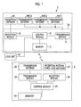
- Fig. 1 is a block diagram showing the configuration of an electronic key device according to a first embodiment.
- Fig. 3 shows the configuration of a vehicle-mounted device according to the first embodiment.
- the electronic key device performs control such that a plurality of vehicle compartment doors 1a and a trunk door 1b are unlocked by providing a vehicle-mounted device 2 on a vehicle 1 and mutually performing wireless communication with a portable device 3 capable of being carried by a user, and performs a predetermined controls of other vehicle 1.
- the door includes the vehicle compartment doors 1a and the trunk door 1b.
- the vehicle-mounted device 2 includes an electronic control unit 2a disposed within the vehicle 1, three transmission antennas ANT1 to ANT3, and a reception antenna 14.
- the electronic control unit 2a includes a vehicle reception module 10 (reception module), a vehicle transmission module 11 (transmission module), a vehicle control module 12 (control module), and a memory 13.
- the vehicle transmission module 11 transmits radio waves to the portable device 3 through the transmission antennas ANT1 to ANT3 every predetermined time (for example, 100 ms), and the vehicle reception module 10 receives a response signal including information related to a distance calculated based on, for example, the reception strength of the radio waves transmitted from the vehicle-mounted device 2 through the reception antenna 14, as a signal transmitted from the portable device 3.
- the response signal transmitted from the portable device 3 may be a signal that does not include a distance.
- the response signal in this case is a signal based on the reception strength of the radio waves transmitted through the transmission antennas ANT1 to ANT3, and the distance is calculated by the vehicle-mounted device 2 that receives the response signal.
- the vehicle control module 12 performs (1) control of the operations of the vehicle reception module 10 and the vehicle transmission module 11, performs (2) approach determination (determination of the moving direction of the portable device 3) of whether or not the portable device 3 heads for any one of the antennas based on the response signal transmitted from the portable device 3, performs (3) distance determination of whether or not a distance between the vehicle 1 and the portable device 3 is equal to or less than a predetermined threshold based on the response signal transmitted from the portable device 3, and performs (4) control such that the vehicle compartment door 1a closest to the antenna facing the portable device 3 becomes unlocked when it is determined that the portable device 3 heads for any one of the transmission antennas ANT1 to ANT3 in the approach determination and it is determined that the distance between the vehicle 1 and the portable device 3 is equal to or less than the predetermined threshold in the distance determination.
- the threshold used in the distance determination is a value corresponding to an approach unlock area Au ( Figs. 3 to 6 ) and the distance is equal to or less than the threshold, it is determined that the portable device 3 is located within
- the approach determination performed by the vehicle control module 12 is as follows.
- the "response signal received at the previous time” includes the response signal received at a time before the “immediately previous time” in addition to the response signal received at the immediately previous time.
- the "predetermined value" used in the determination is set depending on a time interval (predetermined time) during which the radio waves are transmitted to the portable device 3 from the vehicle-mounted device 2, a distance between the portable device 3 and the vehicle 1, the arrangement of the transmission antennas of the vehicle-mounted device 2, and a general walking speed of a human.
- both the determinations (a) and (b) are preferably performed. Particularly, by performing the determination (b), it is possible to more accurately determine whether or not a moving direction of the user who carries the portable device 3 is a direction heading for any one of the antennas between two different times to be compared and which antenna the portable device is headed for.
- a lock unit 32 that locks and unlocks the vehicle compartment doors 1a is connected to the vehicle control module 12, and the vehicle compartment doors 1a are unlocked under the control of the vehicle control module 12.
- the memory 13 stores a unique ID of the vehicle, IDs of a plurality of portable devices capable of operating one vehicle, information required to perform predetermined control of the vehicle 1 based on data based on the reception strength of a measurement signal, and information related to a time interval of the signal transmitted from the vehicle-mounted device 2.
- the three transmission antennas ANT1 to ANT3 for transmitting a signal at a first frequency are connected to the vehicle transmission module 11.
- the first frequency is preferably a low frequency (LF) having a long wavelength in a range of, for example, 30 to 300 kHz, and may be a very low frequency (VLF).
- LF low frequency
- VLF very low frequency
- the transmission antennas ANT1 to ANT3 are respectively provided in different positions of the vehicle 1, for example, near the plurality of vehicle compartment doors 1a and the trunk door 1b as shown in Figs. 3 to 6 .
- the three transmission antennas ANT1 to ANT3 are provided such that the portable device 3 can recognize the radio waves from the respective antennas by using a phase deviation, a frequency difference, transmission timing and a transmission order.
- An approach detection area Ad, and an approach unlock area Au inside the approach detection area are respectively set depending on the communication capacity and arrangement of these transmission antennas ANT1 to ANT3,.
- the approach detection area Ad and the approach unlock area Au that are set to the right door are shown, and the approach detection area Ad and the approach unlock area Au that are set to the left door and the trunk door 1b are not shown.
- the portable device 3 can receive the radio waves transmitted from the transmission antennas ANT1 to ANT 3 near the outside of the approach detection area Ad, and can receive the radio waves by entering an area where it is capable of receiving the radio waves from an area where it is not capable of receiving the radio waves.
- the reception antenna 14 for receiving the signal transmitted from the portable device 3 is connected to the vehicle reception module 10.
- the number of transmission antennas of the vehicle-mounted device 2 may be four or more in consideration of the size of the vehicle, the number of doors, and measurement accuracy.
- the portable device 3 includes a portable-device reception module 20 (reception module), a portable-device transmission module 21 (transmission module), a portable-device control module 22 (control module), a portable-device reception antenna 23 (three-axis antenna), a portable-device transmission antenna 25, and a memory 24.
- the portable-device reception module 20 receives the radio waves transmitted from the vehicle-mounted device 2.
- the portable-device control module 22 calculates distances between the portable device 3 and the three transmission antennas ANT1 to ANT3 of the vehicle-mounted device 2 based on the reception strength of the radio waves received by the portable-device reception module 20, and generates the response signal including these distances, in addition to controlling the operations of the portable-device reception module 20 and the portable-device transmission module 21.
- the portable-device transmission module 21 transmits the response signal including the distances calculated by the portable-device control module 22 to the vehicle-mounted device 2.
- the memory 24 stores an ID set to the portable device 3, an ID of the vehicle, information required to calculate the distances based on the reception strength of the radio waves, and information related to the time interval of the signal transmitted from the portable device 3.
- the reception antenna 23 is connected to the portable-device reception module 20.
- the reception antenna 23 is a three-axis antenna having directivity characteristics in three directions crossing each other, and receives the signal having the first frequency transmitted from the vehicle transmission module 11.
- the transmission antenna 25 is connected to the portable-device transmission module 21.
- the transmission antenna 25 transmits the signal to the vehicle-mounted device 2 at a second frequency.
- the information related to the reception strength for calculating the distances is strength information received by each axis of the three axes of the reception antenna 23.
- the second frequency is a frequency (RF) higher than the first frequency.
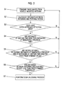
- Fig. 2 is a flowchart showing the flow of processes performed by the electronic key device according to the first embodiment.
- the vehicle transmission module 11 continues to transmit the radio waves to the portable device 3 every predetermined time (step S1).
- the portable device 3 can receive the radio waves from the vehicle transmission module 11, and is in a wake-up state.
- the radio waves transmitted from the vehicle transmission module 11 include a starting part and a strength measurement part, and the portable device 3 is started from a sleep state by the starting part, and is in the wake-up state.
- the portable device 3 calculates the distances between the portable device and the three transmission antennas ANT1 to ANT3 of the vehicle-mounted device 2 based on the reception strength of the radio waves transmitted from the vehicle transmission module 11, and transmits the response signal including the information related to the calculated distances to the vehicle-mounted device 2 (step S2).
- the vehicle-mounted device 2 stores the received response signal in association with time in the memory 13.
- the vehicle control module 12 obtains a position of the portable device 3 with respect to the vehicle 1 from the distances between the portable device 3 and the transmission antennas ATN1 to ANT3 which are included in the response signal transmitted from the portable device 3, and determines whether or not the portable device 3 enters the approach detection area Ad (step S3).
- the antenna which is blocked by the vehicle 1 due to the position of the portable device 3 and in which the portable device 3 is not capable of receiving the radio waves having a strength of a predetermined value or more, is not preferably used as a target in the following determinations. For example, as shown in Figs. 3 to 6 , when the portable device 3 moves from the right in the rear of the vehicle 1, since the radio waves from the antenna ANT2 are blocked by the vehicle 1 and are not received by the portable device 3 with sufficient strength, this antenna is preferably not used as a determination target.
- step S3 The determination process of step S3 is omitted, and step S4 and the subsequent processes may be performed using two or more response signals received after the distances between the portable device 3 and the transmission antennas ANT1 to ANT3 are a predetermined distance (for example, a distance between the vehicle 1 and a boundary of the approach detection area Ad).
- a predetermined distance for example, a distance between the vehicle 1 and a boundary of the approach detection area Ad.
- step S3 while the portable device 3 does not enter the approach detection area Ad (N in step S3), determination of whether or not the portable device 3 enters the approach detection area Ad is repeatedly performed using the distances (step S2) calculated based on the radio waves (step S1) transmitted from the vehicle transmission module 11 every predetermined time. Meanwhile, when it is determined that the portable device 3 enters the approach detection area Ad (Y in step S3), the portable-device control module 22 determines whether or not the distances between the portable device 3 and the three transmission antenna ANT1 to ANT3 are less than the distances at the immediately previous time from the response signal transmitted from the portable device 3 (step S4).
- step S4 when it is determined that the distances between the portable device 3 and the antennas are equal to or greater than the distances at the immediately previous time (N in step S4), the vehicle control module 12 determines that the portable device 3 does not approach any one of the transmission antennas ANT1 to ANT3. Meanwhile, when distances between any of the three transmission antennas ANT1 to ANT3 (both of the antennas ANT1 and ANT3 which are determination targets in the examples of Figs.
- the vehicle control module 12 determines whether or not the ratios "Lbefore/Lafter" obtained by dividing the distances Lbefore at the immediately previous time by the distances Lafter between the portable device 3 and the three transmission antennas ANT1 to ANT3 are greater than a predetermined value Delta (step S5).
- step S5 when the ratios "Lbefore/Lafter” of all the three transmission antennas ANT1 to ANT3 are equal to or less than the predetermined value Delta (N in step S5), the vehicle control module 12 determines that the portable device 3 does not head for any one of the three transmission antennas ANT1 to ANT3. Meanwhile, when the ratios "Lbefore/Lafter” of one or more antennas of the three transmission antennas ANT1 to ANT3 are greater than the predetermined value Delta (Y in step S5), the vehicle control module 12 determines that the portable device 3 heads for the one or more antennas, and determines whether or not the distances between the portable device 3 and the three transmission antennas ANT1 to ANT3 are less than a predetermined threshold (step S6).
- step S6 when the distances between the portable device 3 and all the three transmission antennas ANT1 to ANT3 are equal to or greater than the predetermined threshold (N in step S6), the vehicle control module 12 determines that the portable device 3 does not enter the approach unlock area Au. Meanwhile, when the distances between the portable device 3 and one or more antennas of the three transmission antennas ANT1 to ANT3 are less than the threshold (Y in step S6), the vehicle control module determines that the portable device 3 enters the approach unlock area Au of the one or more antennas, and transmits a signal instructing that the vehicle compartment doors 1a and the trunk door 1b are unlocked to the lock unit 32. The lock unit 32 that receives this signal unlocks the vehicle compartment doors 1a and the trunk door 1b (step S7).
- Figs. 3 to 6 are plan views showing the configuration of the vehicle-mounted device according to the first embodiment, and are diagrams showing Moving Path Examples 1 to 4 of the user.
- Figs. 3 to 6 show examples in which a user U moves from the right in the rear of the vehicle 1, but the first embodiment may be applied to a case where the user moves from other directions.
- the vehicle control module determines whether or not the user approaches the antennas ANT2 and ANT3 instead of the antennas ANT1 and ANT3 in the examples of Figs. 3 to 6 .
- the portable device 3 moves from the right in the rear of the vehicle 1 as shown in Figs. 3 to 6 , since the radio waves from the antenna ANT2 are blocked by the vehicle 1 and are not received by the portable device 3 with sufficient strength, this antenna is excluded from the determination target.
- Example 1 shown in Fig. 3 the user U who carries the portable device 3 is located in a position P11 at a certain time, and moves to a position P12 at a time after one cycle.
- the position P11 is located within the approach detection area Ad
- the position P12 is located within the approach unlock area Au.
- distances between the respective positions and the respective antennas are defined as follows. This definition is similarly applied to Examples 2 to 4.
- the portable device 3 calculates the distances between the respective antennas and the portable device 3 based on the radio waves received from the vehicle-mounted device 2 every predetermined time. When the user comes to the position P11, it is determined that the portable device 3 enters the approach detection area Ad from the distances between the respective antennas and the portable device 3 (steps S1 to S3 of Fig. 2 ).
- the ratios are not limited to the ratios based on the distances at the immediately previous time, that is, the time before one cycle, and may be, for example, ratios based on distances every two cycles or three cycles. The same is true of the Moving Path Examples.
- step S6 of Fig. 2 It is determined that the distances between the position P12 and the respective antennas are less than the predetermined threshold (step S6 of Fig. 2 ).
- the distance between the portable device 3 and any one of the antennas ANT1 and ANT3 is less than the threshold, and it is determined that the portable device 3 is located within the approach unlock area Au.
- Example 2 shown in Fig. 4 the user U who carries the portable device 3 is located in a position P21 at a certain time and moves to a position P22 at a time after one cycle.
- the position P21 is located within the approach detection area Ad
- the position P22 is located within the approach unlock area Au.
- the movement from the position P21 to the position P22 is a movement parallel to the right vehicle compartment door 1a.
- the definition of the distances between the positions P21 and P22 and the respective antennas is the same as that in Example 1, and thus, the description thereof is omitted.
- the portable device 3 calculates the distances between the respective antennas and the portable device 3 based on the radio waves received from the vehicle-mounted device 2 every predetermined time. When the user comes to the position P21, it is determined that the portable device 3 enters the approach detection area Ad from the distances between the respective antennas and the portable device 3 (steps S1 to S3 of Fig. 2 ).
- step S5 of Fig. 2 it is determined whether or not ratios obtained by dividing the distances between the respective antennas and the position P21 at the immediately previous time by the distances between the position P22 and the respective antennas are greater than a predetermined value. Specifically, the relationship of L1-before/L1-after > Delta1 is not satisfied for the antenna ANT1 and L3-before/L3-after > Delta3 is not satisfied for the antenna ANT3. Thus, it is determined that the portable device 3 does not head for any one of the antennas.
- Example 3 shown in Fig. 5 the user U who carries the portable device 3 is located in a position P31 at a certain time and moves to a position P32 at a time after one cycle. Both the positions P31 and P32 are located within the approach unlock area Au, but the movement from the position P31 to the position P32 is a movement parallel to the right vehicle compartment door 1a.
- the definition of the distances between the positions P31 and P32 and the respective antennas is the same as that in Example 1, and thus, the description thereof is omitted.
- the portable device 3 calculates the distances between the portable device 3 and the respective antennas based on the radio waves received from the vehicle-mounted device 2 every predetermined time.
- the portable device 3 enters the approach detection area Ad from the distances between the respective antennas and the portable device 3 (steps S1 to S3 of Fig. 2 ).
- step S5 of Fig. 2 it is determined whether or not ratios obtained by dividing the distances between the respective antennas and the position P31 at the immediately previous time by the distances between the position P32 and the respective antennas are greater than a predetermined value. Specifically, since the relationship of Ll-before/L1-after > Delta1 is not satisfied for the antenna ANT1 and the relationship of L3-before/L3-after > Delta3 is not satisfied for the antenna ANT3, it is determined that the portable device 3 does not head for any antenna.
- Example 4 shown in Fig. 6 the user U who carries the portable device 3 is located in a position P41 at a certain time and moves to a position P42 at a time after one cycle. Both the positions P41 and P42 are located within the approach unlock area Au. As the portable device moves from the position P41 toward the position P42, the portable device 3 approaches the vehicle 1.
- the definition of the distances between the positions P41 and P42 and the respective antennas is the same as that in Example 1, and thus, the description thereof is omitted.
- the portable device 3 calculates the distances between the respective antennas and the portable device 3 based on the radio waves received from the vehicle-mounted device 2 every predetermined time.
- the portable device 3 enters the approach detection area Ad from the distances between the respective antennas and the portable device 3 (steps S1 to S3 of Fig. 2 ).
- step S4 of Fig. 2 the distances between the position P42 and the respective antennas are calculated, and it is determined whether or not the distances in this case are less than the distances at the immediately previous time, that is, the distances between the position P41 and the respective antennas. Specifically, since the relationship of L1-before > L1-after is satisfied for the antenna ANT1 and the relationship of L3-before > L3-after is satisfied for the antenna ANT3, it is determined that the portable device 3 approaches both of the antennas ANT1 and ANT3.
- step S5 of Fig. 2 it is determined whether or not ratios obtained by dividing the distances between the respective antennas and the position P41 at the immediately previous time by the distances between the position P42 and the respective antennas are greater than a predetermined value. Specifically, since the relationship of Ll-before/L1-after > Delta1 is satisfied for the antenna ANT1 and the relationship of L3-before/L3-after > Delta3 is not satisfied for the antenna ANT3, it is determined that the portable device 3 heads for the antenna ANT1.
- step S6 of Fig. 2 It is determined whether or not the distances between the position P42 and the respective antennas are less than a predetermined threshold (step S6 of Fig. 2 ).
- the distances between the portable device 3 and both of the antennas ANT1 and ANT3 are less than the threshold, and it is determined that the portable device 3 is located within the approach unlock area Au.
- the distances between the portable device 3 and the three transmission antennas ANT1 to ANT3 of the vehicle-mounted device 2 are calculated based on the reception strength of the radio waves received by the portable device 3, and the response signal including the information related to the calculated distances is transmitted to the vehicle-mounted device 2.
- the portable device 3 may transmit the reception strength of the received radio waves to the vehicle-mounted device 2, and the vehicle control module 12 may calculate the distances between the portable device 3 and the three transmission antennas ANT1 to ANT3 of the vehicle-mounted device 2.
- the three transmission antennas ANT1 to ANT3 are respectively provided near the two rear vehicle compartment doors and the trunk door, but the number and arrangement of transmission antennas are not limited thereto. For example, it is possible to perform a more accurate determination by providing the transmission antennas near all four vehicle compartment doors.
- the response signal including the information related to the distances between the antennas and the portable device is transmitted from the portable device 3 to the vehicle-mounted device every cycle, based on the reception strength of the radio waves transmitted from the three antennas ANT1 to ANT3.
- the distances between the respective antennas and the portable device 3 and the moving direction of the portable device 3 are determined from the response signal, and it is determined that the moving direction of the portable device 3 heads for any of the antennas.
- control is performed such that the vehicle compartment door 1a closest to the antenna for which the portable device 3 heads becomes unlocked.
- the three antennas ANT1 to ANT3 are provided near the vehicle compartment doors 1a of the vehicle 1 and near the trunk door 1b.
- the portable device 3 it is determined whether or not the portable device 3 heads for any one of the antennas from the ratio and the difference between the distances included in the response signal transmitted from the portable device 3 and the distances included in the response signal received at the previous time.
- the second embodiment based on the reception strength of the radio waves received by the respective axes of the reception antenna 23 (three-axis reception antenna) of the portable device 3, a reception vector indicating a direction in which the reception strength is the highest based on the reception strength in three directions crossing each other is calculated, and a response signal including this reception vector is transmitted to the vehicle-mounted device 2.
- the reception vector is a quantity having reception strength and direction.
- the vehicle control module 12 determines whether or not the moving direction of the portable device 3 heads for any one of the antennas from information related to the reception vector included in the response signal.
- Other configurations are the same as those in the first embodiment, and thus, the detailed description thereof is omitted.
- the approach determination performed by the vehicle control module 12 is as follows.
- (b) It is determined whether or not the moving direction of the portable device 3 heads for any antenna based on the information related to the reception vector included in the response signal transmitted from the portable device 3. For example, when a time change in the direction of the reception vector is less than a predetermined value, it is determined that the portable device heads for any one of the antennas.
- the electronic key device can have a simple configuration, and it is possible to reduce a load in the determination process performed by the vehicle-mounted device 2.
- the electronic key device determines whether or not the user tries to enter the vehicle based on the moving direction of the portable device carried by the user, and it is possible to perform the unlocking process only when the user tries to enter the vehicle. Accordingly, it is possible to prevent the door from being unlocked in an unintended situation.
Landscapes
- Engineering & Computer Science (AREA)
- Mechanical Engineering (AREA)
- Computer Networks & Wireless Communication (AREA)
- Physics & Mathematics (AREA)
- General Physics & Mathematics (AREA)
- Lock And Its Accessories (AREA)
- Selective Calling Equipment (AREA)
Abstract
Description
- This application claims benefit of Japanese Patent Application No.
2014-136458 filed on July 2, 2014 - The present invention relates to an electronic key device configured to perform predetermined control such as unlocking of doors of a vehicle by performing mutual communication between a vehicle-mounted device and a portable device.
- In a radio device described in Japanese Unexamined Patent Application Publication No.
2007-132139 - In a control system described in
JP 2012-17558 A - However, in the radio device described in
JP 2007-132139 A JP 2012-17558 A - The present invention provides an electronic key device configured to reliably unlock doors or a trunk of a vehicle only when a user who enters an approach unlock area approaches the doors or the trunk.
- According to an aspect of the present invention, there is provided an electronic key device including a portable device capable of being carried by a user; and a vehicle-mounted device configured to perform mutual communication with the portable device to perform predetermined control. The vehicle-mounted device includes a plurality of antennas that is provided in different positions of a vehicle and is configured to transmit radio waves every predetermined time. A response signal based on the reception strength of the radio waves transmitted from the plurality of antennas is transmitted from the portable device to the vehicle-mounted device. The vehicle-mounted device determines that a moving direction of the portable device heads for any one of the antennas based on the response signal, and when it is determined that a distance between the vehicle and the portable device is equal to or less than a predetermined threshold, control is performed such that a door becomes unlocked.
- Here, the phrase "radio waves are transmitted every predetermined time" includes a case where the transmission interval of the radio waves is changed during the transmission in addition to a case where the radio waves are transmitted every regular cycle.
- Thus, when a user enters an approach unlock area, and only when the user approaches toward vehicle compartment doors and a trunk door of a vehicle, that is, only when the user tries to enter the vehicle, it is possible to reliably unlock the door.
- In the electronic key device according to the aspect of the present invention, when it is determined that a distance between the antenna and the portable device is less than the distance obtained from the response signal received at the previous time by a predetermined percentage or more or a predetermined difference or more, the vehicle-mounted device may determine that the portable device heads for any one of the antennas.
- Here, the "response signal received at the previous time" includes a response signal received at a time before the "immediately previous time" in addition to the response signal received at the immediately previous time" which is a time before a predetermined time.
- As mentioned above, since the determination is performed using the ratio or the differences between the distances at two different times, it is possible to reliably determine the moving direction of the user who carries the portable device with a simple configuration. Here, the ratio is not limited to the ratio based on the distance at the immediately previous time, that is, the time before one cycle, and may be a ratio based on distances every two cycles or every three cycles.
- In the electronic key device according to the aspect of the present invention, the portable device may include a three-axis antenna capable of detecting reception strength in three directions crossing each other, and may calculate a reception vector indicating a direction in which the reception strength is the highest based on the reception strength from the three directions. The vehicle-mounted device may determine whether or not a moving direction of the portable device heads for any one of the antennas from information related to the reception vector included in the response signal.
- Accordingly, since it is determined whether or not the moving direction of the portable device heads for any one of the antennas from the information related to the reception vector, the electronic key device can have a simple configuration, and it is possible to reduce a load in the determination process of the vehicle-mounted device.
- In the electronic key device according to the aspect of the present invention, when a time change in the direction of the reception vector is less than a predetermined value, it may be determined that the moving direction of the portable device heads for any one of the antennas.
- The reception vector is a quantity having reception strength and direction. However, the determination is performed by a time change in the direction of the reception vector.
- In the electronic key device according to the aspect of the present invention, the plurality of antennas may be provided near vehicle compartment doors of the vehicle and near a trunk door.
- Accordingly, since it is possible to specifically determine which door the user tries to approach, it is possible to reliably unlock the door only when the user tries to enter the vehicle.
- In the electronic key device according to the aspect of the present invention, when it is determined that the moving direction of the portable device heads for any one of the antennas and the distance between the vehicle and the portable device is equal to or less than a predetermined threshold, control may be performed such that the door closest to the antenna for which the portable device heads becomes unlocked.
-
-
Fig. 1 is a block diagram showing the configuration of an electronic key device according to a first embodiment; -
Fig. 2 is a flowchart showing the flow of processes performed by the electronic key device according to the first embodiment; -
Fig. 3 is a plan view showing the configuration of a vehicle-mounted device according to the first embodiment, and is a diagram showing Moving Path Example 1 of a user; -
Fig. 4 is a plan view showing the configuration of a vehicle-mounted device according to the first embodiment, and is a diagram showing Moving Path Example 2 of the user; -
Fig. 5 is a plan view showing the configuration of a vehicle-mounted device according to the first embodiment, and is a diagram showing Moving Path Example 3 of the user; and -
Fig. 6 is a plan view showing the configuration of a vehicle-mounted device according to the first embodiment, and is a diagram showing Moving Path Example 4 of the user. - Hereinafter, an electronic key device according to embodiments of the present invention will be described in detail with reference to the drawings.
-
Fig. 1 is a block diagram showing the configuration of an electronic key device according to a first embodiment.Fig. 3 shows the configuration of a vehicle-mounted device according to the first embodiment. - The electronic key device according to the first embodiment performs control such that a plurality of
vehicle compartment doors 1a and atrunk door 1b are unlocked by providing a vehicle-mounteddevice 2 on avehicle 1 and mutually performing wireless communication with aportable device 3 capable of being carried by a user, and performs a predetermined controls ofother vehicle 1. Here, the door includes thevehicle compartment doors 1a and thetrunk door 1b. - The vehicle-mounted
device 2 includes anelectronic control unit 2a disposed within thevehicle 1, three transmission antennas ANT1 to ANT3, and a reception antenna 14. Theelectronic control unit 2a includes a vehicle reception module 10 (reception module), a vehicle transmission module 11 (transmission module), a vehicle control module 12 (control module), and amemory 13. - The
vehicle transmission module 11 transmits radio waves to theportable device 3 through the transmission antennas ANT1 to ANT3 every predetermined time (for example, 100 ms), and thevehicle reception module 10 receives a response signal including information related to a distance calculated based on, for example, the reception strength of the radio waves transmitted from the vehicle-mounteddevice 2 through the reception antenna 14, as a signal transmitted from theportable device 3. - The response signal transmitted from the
portable device 3 may be a signal that does not include a distance. The response signal in this case is a signal based on the reception strength of the radio waves transmitted through the transmission antennas ANT1 to ANT3, and the distance is calculated by the vehicle-mounteddevice 2 that receives the response signal. - The
vehicle control module 12 performs (1) control of the operations of thevehicle reception module 10 and thevehicle transmission module 11, performs (2) approach determination (determination of the moving direction of the portable device 3) of whether or not theportable device 3 heads for any one of the antennas based on the response signal transmitted from theportable device 3, performs (3) distance determination of whether or not a distance between thevehicle 1 and theportable device 3 is equal to or less than a predetermined threshold based on the response signal transmitted from theportable device 3, and performs (4) control such that thevehicle compartment door 1a closest to the antenna facing theportable device 3 becomes unlocked when it is determined that theportable device 3 heads for any one of the transmission antennas ANT1 to ANT3 in the approach determination and it is determined that the distance between thevehicle 1 and theportable device 3 is equal to or less than the predetermined threshold in the distance determination. Here, when the threshold used in the distance determination is a value corresponding to an approach unlock area Au (Figs. 3 to 6 ) and the distance is equal to or less than the threshold, it is determined that theportable device 3 is located within the approach unlock area Au. - More specifically, the approach determination performed by the
vehicle control module 12 is as follows. - (a) It is determined that the
portable device 3 heads for any one of the antennas when it is determined that the distance included in the response signal transmitted from theportable device 3 is less than the distance included in the response signal received at a previous time (for example, a time before a predetermined time (immediately previous time)). - Here, the "response signal received at the previous time" includes the response signal received at a time before the "immediately previous time" in addition to the response signal received at the immediately previous time.
- (b) When a ratio "Lbefore/Lafter" of a distance Lafter included in the response signal transmitted from the
portable device 3 to a distance Lbefore included in the response signal received at the previous time is equal to or greater than a predetermined value, or when a difference "Lbefore-Lafter" between the distance Lafter included in the response signal and the distance Lbefore included in the response signal received at the previous time is equal to or greater than a predetermined value, the distance included in the response signal is shorter than the distance included in the response signal received at the previous time. In this case, it is determined that the portable device heads for any one of the antennas. - Here, when a case where the user heads for the
vehicle compartment door 1a of thevehicle 1 as shown inFig. 3 is compared with a case where the user moves in parallel with thevehicle compartment door 1a of thevehicle 1 as shown inFig. 4 , a time change of "Lafter" with respect to "Lbefore" is small in the case shown inFig. 4 , whereas a time change is large when the user walks toward thevehicle compartment door 1a (AMT1) as shown inFig. 3 . Accordingly, it is possible to determine that the portable device heads for any one of the antennas by using the ratio "Lbefore/Lafter" or the difference "Lbefore-Lafter" corresponding to the time change. - Here, the "predetermined value" used in the determination is set depending on a time interval (predetermined time) during which the radio waves are transmitted to the
portable device 3 from the vehicle-mounteddevice 2, a distance between theportable device 3 and thevehicle 1, the arrangement of the transmission antennas of the vehicle-mounteddevice 2, and a general walking speed of a human. - Here, as the approach determination, both the determinations (a) and (b) are preferably performed. Particularly, by performing the determination (b), it is possible to more accurately determine whether or not a moving direction of the user who carries the
portable device 3 is a direction heading for any one of the antennas between two different times to be compared and which antenna the portable device is headed for. - A
lock unit 32 that locks and unlocks thevehicle compartment doors 1a is connected to thevehicle control module 12, and thevehicle compartment doors 1a are unlocked under the control of thevehicle control module 12. - The
memory 13 stores a unique ID of the vehicle, IDs of a plurality of portable devices capable of operating one vehicle, information required to perform predetermined control of thevehicle 1 based on data based on the reception strength of a measurement signal, and information related to a time interval of the signal transmitted from the vehicle-mounteddevice 2. - The three transmission antennas ANT1 to ANT3 for transmitting a signal at a first frequency are connected to the
vehicle transmission module 11. Here, the first frequency is preferably a low frequency (LF) having a long wavelength in a range of, for example, 30 to 300 kHz, and may be a very low frequency (VLF). - The transmission antennas ANT1 to ANT3 are respectively provided in different positions of the
vehicle 1, for example, near the plurality ofvehicle compartment doors 1a and thetrunk door 1b as shown inFigs. 3 to 6 . The three transmission antennas ANT1 to ANT3 are provided such that theportable device 3 can recognize the radio waves from the respective antennas by using a phase deviation, a frequency difference, transmission timing and a transmission order. - An approach detection area Ad, and an approach unlock area Au inside the approach detection area (
Figs. 3 to 6 ) are respectively set depending on the communication capacity and arrangement of these transmission antennas ANT1 to ANT3,. Here, inFigs. 3 to 6 , the approach detection area Ad and the approach unlock area Au that are set to the right door are shown, and the approach detection area Ad and the approach unlock area Au that are set to the left door and thetrunk door 1b are not shown. - The
portable device 3 can receive the radio waves transmitted from the transmission antennas ANT1 toANT 3 near the outside of the approach detection area Ad, and can receive the radio waves by entering an area where it is capable of receiving the radio waves from an area where it is not capable of receiving the radio waves. Thus, the state of the portable device is changed from a stand-by state to a wake-up state. The reception antenna 14 for receiving the signal transmitted from theportable device 3 is connected to thevehicle reception module 10. The number of transmission antennas of the vehicle-mounteddevice 2 may be four or more in consideration of the size of the vehicle, the number of doors, and measurement accuracy. - As shown in
Fig. 1 , theportable device 3 includes a portable-device reception module 20 (reception module), a portable-device transmission module 21 (transmission module), a portable-device control module 22 (control module), a portable-device reception antenna 23 (three-axis antenna), a portable-device transmission antenna 25, and amemory 24. - The portable-
device reception module 20 receives the radio waves transmitted from the vehicle-mounteddevice 2. The portable-device control module 22 calculates distances between theportable device 3 and the three transmission antennas ANT1 to ANT3 of the vehicle-mounteddevice 2 based on the reception strength of the radio waves received by the portable-device reception module 20, and generates the response signal including these distances, in addition to controlling the operations of the portable-device reception module 20 and the portable-device transmission module 21. The portable-device transmission module 21 transmits the response signal including the distances calculated by the portable-device control module 22 to the vehicle-mounteddevice 2. Thememory 24 stores an ID set to theportable device 3, an ID of the vehicle, information required to calculate the distances based on the reception strength of the radio waves, and information related to the time interval of the signal transmitted from theportable device 3. - The
reception antenna 23 is connected to the portable-device reception module 20. Thereception antenna 23 is a three-axis antenna having directivity characteristics in three directions crossing each other, and receives the signal having the first frequency transmitted from thevehicle transmission module 11. Thetransmission antenna 25 is connected to the portable-device transmission module 21. Thetransmission antenna 25 transmits the signal to the vehicle-mounteddevice 2 at a second frequency. The information related to the reception strength for calculating the distances is strength information received by each axis of the three axes of thereception antenna 23. Here, the second frequency is a frequency (RF) higher than the first frequency. - Next, the flow of unlock control performed by the electronic key device will be described with reference to
Fig. 2. Fig. 2 is a flowchart showing the flow of processes performed by the electronic key device according to the first embodiment. - The
vehicle transmission module 11 continues to transmit the radio waves to theportable device 3 every predetermined time (step S1). When the user who carries theportable device 3 approaches up to an area near the outside of the approach detection area Ad, theportable device 3 can receive the radio waves from thevehicle transmission module 11, and is in a wake-up state. Here, the radio waves transmitted from thevehicle transmission module 11 include a starting part and a strength measurement part, and theportable device 3 is started from a sleep state by the starting part, and is in the wake-up state. - The
portable device 3 calculates the distances between the portable device and the three transmission antennas ANT1 to ANT3 of the vehicle-mounteddevice 2 based on the reception strength of the radio waves transmitted from thevehicle transmission module 11, and transmits the response signal including the information related to the calculated distances to the vehicle-mounted device 2 (step S2). The vehicle-mounteddevice 2 stores the received response signal in association with time in thememory 13. - The
vehicle control module 12 obtains a position of theportable device 3 with respect to thevehicle 1 from the distances between theportable device 3 and the transmission antennas ATN1 to ANT3 which are included in the response signal transmitted from theportable device 3, and determines whether or not theportable device 3 enters the approach detection area Ad (step S3). Here, the antenna, which is blocked by thevehicle 1 due to the position of theportable device 3 and in which theportable device 3 is not capable of receiving the radio waves having a strength of a predetermined value or more, is not preferably used as a target in the following determinations. For example, as shown inFigs. 3 to 6 , when theportable device 3 moves from the right in the rear of thevehicle 1, since the radio waves from the antenna ANT2 are blocked by thevehicle 1 and are not received by theportable device 3 with sufficient strength, this antenna is preferably not used as a determination target. - The determination process of step S3 is omitted, and step S4 and the subsequent processes may be performed using two or more response signals received after the distances between the
portable device 3 and the transmission antennas ANT1 to ANT3 are a predetermined distance (for example, a distance between thevehicle 1 and a boundary of the approach detection area Ad). - In step S3, while the
portable device 3 does not enter the approach detection area Ad (N in step S3), determination of whether or not theportable device 3 enters the approach detection area Ad is repeatedly performed using the distances (step S2) calculated based on the radio waves (step S1) transmitted from thevehicle transmission module 11 every predetermined time. Meanwhile, when it is determined that theportable device 3 enters the approach detection area Ad (Y in step S3), the portable-device control module 22 determines whether or not the distances between theportable device 3 and the three transmission antenna ANT1 to ANT3 are less than the distances at the immediately previous time from the response signal transmitted from the portable device 3 (step S4). - In step S4, when it is determined that the distances between the
portable device 3 and the antennas are equal to or greater than the distances at the immediately previous time (N in step S4), thevehicle control module 12 determines that theportable device 3 does not approach any one of the transmission antennas ANT1 to ANT3. Meanwhile, when distances between any of the three transmission antennas ANT1 to ANT3 (both of the antennas ANT1 and ANT3 which are determination targets in the examples ofFigs. 3 to 6 ) and theportable device 3 are less than the distances of the immediately previous time (Y in step S4), thevehicle control module 12 determines whether or not the ratios "Lbefore/Lafter" obtained by dividing the distances Lbefore at the immediately previous time by the distances Lafter between theportable device 3 and the three transmission antennas ANT1 to ANT3 are greater than a predetermined value Delta (step S5). - In step S5, when the ratios "Lbefore/Lafter" of all the three transmission antennas ANT1 to ANT3 are equal to or less than the predetermined value Delta (N in step S5), the
vehicle control module 12 determines that theportable device 3 does not head for any one of the three transmission antennas ANT1 to ANT3. Meanwhile, when the ratios "Lbefore/Lafter" of one or more antennas of the three transmission antennas ANT1 to ANT3 are greater than the predetermined value Delta (Y in step S5), thevehicle control module 12 determines that theportable device 3 heads for the one or more antennas, and determines whether or not the distances between theportable device 3 and the three transmission antennas ANT1 to ANT3 are less than a predetermined threshold (step S6). - In step S6, when the distances between the
portable device 3 and all the three transmission antennas ANT1 to ANT3 are equal to or greater than the predetermined threshold (N in step S6), thevehicle control module 12 determines that theportable device 3 does not enter the approach unlock area Au. Meanwhile, when the distances between theportable device 3 and one or more antennas of the three transmission antennas ANT1 to ANT3 are less than the threshold (Y in step S6), the vehicle control module determines that theportable device 3 enters the approach unlock area Au of the one or more antennas, and transmits a signal instructing that thevehicle compartment doors 1a and thetrunk door 1b are unlocked to thelock unit 32. Thelock unit 32 that receives this signal unlocks thevehicle compartment doors 1a and thetrunk door 1b (step S7). - Next, specific determination examples will be described with reference to
Figs. 3 to 6. Figs. 3 to 6 are plan views showing the configuration of the vehicle-mounted device according to the first embodiment, and are diagrams showing Moving Path Examples 1 to 4 of the user.Figs. 3 to 6 show examples in which a user U moves from the right in the rear of thevehicle 1, but the first embodiment may be applied to a case where the user moves from other directions. For example, when the user moves from the left in the rear, the vehicle control module determines whether or not the user approaches the antennas ANT2 and ANT3 instead of the antennas ANT1 and ANT3 in the examples ofFigs. 3 to 6 . Here, when theportable device 3 moves from the right in the rear of thevehicle 1 as shown inFigs. 3 to 6 , since the radio waves from the antenna ANT2 are blocked by thevehicle 1 and are not received by theportable device 3 with sufficient strength, this antenna is excluded from the determination target. - In Example 1 shown in
Fig. 3 , the user U who carries theportable device 3 is located in a position P11 at a certain time, and moves to a position P12 at a time after one cycle. The position P11 is located within the approach detection area Ad, and the position P12 is located within the approach unlock area Au. As the portable device moves from the position P11 toward the position P12, theportable device 3 approaches thevehicle 1. Here, distances between the respective positions and the respective antennas are defined as follows. This definition is similarly applied to Examples 2 to 4. - Distance between position P11 and antenna ANT1: L1-before,
- Distance between position P11 and antenna ANT3: L3-before,
- Distance between position P12 and antenna ANT1: L1-after, and
- Distance between position P12 and antenna ANT3: L3-after.
- The flow of processes performed by the electronic key device in this case is as follows.
- (1) The
portable device 3 calculates the distances between the respective antennas and theportable device 3 based on the radio waves received from the vehicle-mounteddevice 2 every predetermined time. When the user comes to the position P11, it is determined that theportable device 3 enters the approach detection area Ad from the distances between the respective antennas and the portable device 3 (steps S1 to S3 ofFig. 2 ). - (2) Subsequently, when the user moves to the position P12, distances between the position P12 and the respective antennas are calculated, and it is determined whether or not these distances are less than the distances at the immediately previous time, that is, the distances between the position P11 and the respective antennas (step S4 of
Fig. 2 ). Specifically, since the relationship of L1-before > L1-after is satisfied for the antenna ANT1 and the relationship of L3-before > L3-after is satisfied for the antenna ANT3, it is determined that theportable device 3 approaches any one of the antennas ANT1 and ANT3. - (3) Thereafter, it is determined whether or not ratios obtained by dividing the distances between the respective antennas and the position P11 at the immediately previous time by the distances between the position P12 and the respective antennas are greater than a predetermined value (step S5 of
Fig. 2 ). - Specifically, since the relationship of L1-before/L1-after > Delta1 is satisfied for the antenna ANT1 and the relationship of L3-before/L3-after > Delta3 is not satisfied for the antenna ANT3, it is determined that the
portable device 3 heads for the antenna ANT1. - The ratios are not limited to the ratios based on the distances at the immediately previous time, that is, the time before one cycle, and may be, for example, ratios based on distances every two cycles or three cycles. The same is true of the Moving Path Examples.
- (4) It is determined that the distances between the position P12 and the respective antennas are less than the predetermined threshold (step S6 of
Fig. 2 ). In Example 1 shown inFig. 3 , the distance between theportable device 3 and any one of the antennas ANT1 and ANT3 is less than the threshold, and it is determined that theportable device 3 is located within the approach unlock area Au. - (5) Through the determinations of (1) to (4) described above, it is determined that the
portable device 3 moves up to the position P12 within the approach unlock area Au from the position P11 of the approach detection area Ad and approaches thevehicle 1 and moves toward the antenna ANT1, and thus, the process of unlocking the door near the antenna ANT1 is performed. - In Example 2 shown in
Fig. 4 , the user U who carries theportable device 3 is located in a position P21 at a certain time and moves to a position P22 at a time after one cycle. The position P21 is located within the approach detection area Ad, and the position P22 is located within the approach unlock area Au. However, the movement from the position P21 to the position P22 is a movement parallel to the rightvehicle compartment door 1a. Here, the definition of the distances between the positions P21 and P22 and the respective antennas is the same as that in Example 1, and thus, the description thereof is omitted. - The flow of processes performed by the electronic key device in this case is as follows.
- (1) The
portable device 3 calculates the distances between the respective antennas and theportable device 3 based on the radio waves received from the vehicle-mounteddevice 2 every predetermined time. When the user comes to the position P21, it is determined that theportable device 3 enters the approach detection area Ad from the distances between the respective antennas and the portable device 3 (steps S1 to S3 ofFig. 2 ). - (2) Subsequently, when the user moves to the position P22, distances between the position P22 and the respective antennas are calculated, it is determined that these distances are less than the distances at the immediately previous time, that is, the distances between the position P21 and the respective antennas (step S4 of
Fig. 2 ). Specifically, since the relationship of L1-before > L1-after is satisfied for the antenna ANT1 and the relationship of L3-fefore > L3-after is satisfied for the antenna ANT3, it is determined that theportable device 3 approaches both the antennas ANT1 and ANT3. - (3) Subsequently, it is determined whether or not ratios obtained by dividing the distances between the respective antennas and the position P21 at the immediately previous time by the distances between the position P22 and the respective antennas are greater than a predetermined value (step S5 of
Fig. 2 ). Specifically, the relationship of L1-before/L1-after > Delta1 is not satisfied for the antenna ANT1 and L3-before/L3-after > Delta3 is not satisfied for the antenna ANT3. Thus, it is determined that theportable device 3 does not head for any one of the antennas. - (4) Through the determinations of (1) to (3) described above, it is determined that the
portable device 3 moves from the position P21 of the approach detection area Ad up to the position P22 within the approach unlock area Au but moves without heading for any one of the antennas. Thus, the locked state of thevehicle 1 is maintained. - In Example 3 shown in
Fig. 5 , the user U who carries theportable device 3 is located in a position P31 at a certain time and moves to a position P32 at a time after one cycle. Both the positions P31 and P32 are located within the approach unlock area Au, but the movement from the position P31 to the position P32 is a movement parallel to the rightvehicle compartment door 1a. Here, the definition of the distances between the positions P31 and P32 and the respective antennas is the same as that in Example 1, and thus, the description thereof is omitted. - The flow of processes performed by the electronic key device in this case is as follows.
- (1) The
portable device 3 calculates the distances between theportable device 3 and the respective antennas based on the radio waves received from the vehicle-mounteddevice 2 every predetermined time. When the user enters the approach detection area Ad and comes up to the position P31, it is determined that theportable device 3 enters the approach detection area Ad from the distances between the respective antennas and the portable device 3 (steps S1 to S3 ofFig. 2 ). - (2) Thereafter, when the user moves toward the position P32, distances between the position P32 and the respective antennas are calculated, and it is determined whether or not these distances are less than the distances at the immediately previous time, that is, the distances between the position P31 and the respective antennas (step S4 of
Fig. 2 ). Specifically, since the relationship of L1-before > L1-after is satisfied for the antenna ANT1 and the relationship of L3-before > L3-after is not satisfied for the antenna ANT3, it is determined that theportable device 3 does not approach the antenna ANT3. - (3) Subsequently, it is determined whether or not ratios obtained by dividing the distances between the respective antennas and the position P31 at the immediately previous time by the distances between the position P32 and the respective antennas are greater than a predetermined value (step S5 of
Fig. 2 ). Specifically, since the relationship of Ll-before/L1-after > Delta1 is not satisfied for the antenna ANT1 and the relationship of L3-before/L3-after > Delta3 is not satisfied for the antenna ANT3, it is determined that theportable device 3 does not head for any antenna. - (4) Through the determinations of (1) to (3) described above, it is determined that the
portable device 3 moves up to the position P32 from the position P31 and does not approach thevehicle 1, and thus, the locked stage of thevehicle 1 is maintained. - In Example 4 shown in
Fig. 6 , the user U who carries theportable device 3 is located in a position P41 at a certain time and moves to a position P42 at a time after one cycle. Both the positions P41 and P42 are located within the approach unlock area Au. As the portable device moves from the position P41 toward the position P42, theportable device 3 approaches thevehicle 1. Here, the definition of the distances between the positions P41 and P42 and the respective antennas is the same as that in Example 1, and thus, the description thereof is omitted. - The flow of processes performed by the electronic key device in this case is as follows.
- (1) The
portable device 3 calculates the distances between the respective antennas and theportable device 3 based on the radio waves received from the vehicle-mounteddevice 2 every predetermined time. When the user enters the approach detection area Ad and comes up to the position P41, it is determined that theportable device 3 enters the approach detection area Ad from the distances between the respective antennas and the portable device 3 (steps S1 to S3 ofFig. 2 ). - (2) Subsequently, when the user moves toward the position P42, distances between the position P42 and the respective antennas are calculated, and it is determined whether or not the distances in this case are less than the distances at the immediately previous time, that is, the distances between the position P41 and the respective antennas (step S4 of
Fig. 2 ). Specifically, since the relationship of L1-before > L1-after is satisfied for the antenna ANT1 and the relationship of L3-before > L3-after is satisfied for the antenna ANT3, it is determined that theportable device 3 approaches both of the antennas ANT1 and ANT3. - (3) Thereafter, it is determined whether or not ratios obtained by dividing the distances between the respective antennas and the position P41 at the immediately previous time by the distances between the position P42 and the respective antennas are greater than a predetermined value (step S5 of
Fig. 2 ). Specifically, since the relationship of Ll-before/L1-after > Delta1 is satisfied for the antenna ANT1 and the relationship of L3-before/L3-after > Delta3 is not satisfied for the antenna ANT3, it is determined that theportable device 3 heads for the antenna ANT1. - (4) It is determined whether or not the distances between the position P42 and the respective antennas are less than a predetermined threshold (step S6 of
Fig. 2 ). In Example 4 shown inFig. 6 , the distances between theportable device 3 and both of the antennas ANT1 and ANT3 are less than the threshold, and it is determined that theportable device 3 is located within the approach unlock area Au. - (5) Through the determinations of (1) to (4) described above, it is determined that the
portable device 3 moves up to the position P42 within the approach unlock area Au from the position P41 of the approach detection area Ad and approaches thevehicle 1 and moves toward the antenna ANT1, and thus, the process of unlocking the antenna ANT1 is performed. - A modification example will be described below.
- In the first embodiment, the distances between the
portable device 3 and the three transmission antennas ANT1 to ANT3 of the vehicle-mounteddevice 2 are calculated based on the reception strength of the radio waves received by theportable device 3, and the response signal including the information related to the calculated distances is transmitted to the vehicle-mounteddevice 2. Meanwhile, in the second embodiment, theportable device 3 may transmit the reception strength of the received radio waves to the vehicle-mounteddevice 2, and thevehicle control module 12 may calculate the distances between theportable device 3 and the three transmission antennas ANT1 to ANT3 of the vehicle-mounteddevice 2. - In the first embodiment, the three transmission antennas ANT1 to ANT3 are respectively provided near the two rear vehicle compartment doors and the trunk door, but the number and arrangement of transmission antennas are not limited thereto. For example, it is possible to perform a more accurate determination by providing the transmission antennas near all four vehicle compartment doors.
- In such a configuration, according to the above embodiments, the following effects are exhibited.
- (1) The response signal including the information related to the distances between the antennas and the portable device is transmitted from the
portable device 3 to the vehicle-mounted device every cycle, based on the reception strength of the radio waves transmitted from the three antennas ANT1 to ANT3. In the vehicle-mounteddevice 2, the distances between the respective antennas and theportable device 3 and the moving direction of theportable device 3 are determined from the response signal, and it is determined that the moving direction of theportable device 3 heads for any of the antennas. When it is determined that the distance between thevehicle 1 and theportable device 3 is equal to or less than the predetermined threshold, control is performed such that thevehicle compartment door 1a closest to the antenna for which theportable device 3 heads becomes unlocked. - Thus, when the user enters the approach unlock area Au, and only when the user approaches toward the
vehicle compartment doors 1a and thetrunk door 1b of thevehicle 1, that is, only when the user tries to enter thevehicle 1, it is possible to reliably unlock the door. In other words, it is possible to reliably determine the case where the user tries to enter thevehicle 1 as mentioned above and a case where a user who does not try to enter thevehicle 1 passes the approach unlock area Au, and even when the user who does not try to enter thevehicle 1 approaches the vehicle, the unlocking process is not performed. - (2) When it is determined that the distances between the
portable device 3 and the three antennas ANT1 to ANT3 are less than the distances obtained from the response signal received at the previous time by a predetermined percentage or more or a predetermined difference or more, it is determined that theportable device 3 heads for any one of the antennas. - Since the determinations are performed using the ratio and the difference between the distances at two different times, it is possible to reliably determine the moving direction of the user who carries the
portable device 3 with a simple configuration. - (3) The three antennas ANT1 to ANT3 are provided near the
vehicle compartment doors 1a of thevehicle 1 and near thetrunk door 1b. - Thus, since it is possible to specifically determine which door the user tries to approach, it is possible to reliably unlock the door only when the user tries to enter the
vehicle 1. - Next, a second embodiment of the present invention will be described. In the first embodiment, it is determined whether or not the
portable device 3 heads for any one of the antennas from the ratio and the difference between the distances included in the response signal transmitted from theportable device 3 and the distances included in the response signal received at the previous time. Meanwhile, in the second embodiment, based on the reception strength of the radio waves received by the respective axes of the reception antenna 23 (three-axis reception antenna) of theportable device 3, a reception vector indicating a direction in which the reception strength is the highest based on the reception strength in three directions crossing each other is calculated, and a response signal including this reception vector is transmitted to the vehicle-mounteddevice 2. Here, the reception vector is a quantity having reception strength and direction. - In the vehicle-mounted
device 2, thevehicle control module 12 determines whether or not the moving direction of theportable device 3 heads for any one of the antennas from information related to the reception vector included in the response signal. Other configurations are the same as those in the first embodiment, and thus, the detailed description thereof is omitted. - In the second embodiment, the approach determination performed by the
vehicle control module 12 is as follows. - (a) When it is determined that the distances included in the response signal transmitted from the
portable device 3 are less than the distances included in the response signal received at the previous time (for example, a time before a predetermined time), it is determined that theportable device 3 heads for any one of the antennas. - (b) It is determined whether or not the moving direction of the
portable device 3 heads for any antenna based on the information related to the reception vector included in the response signal transmitted from theportable device 3. For example, when a time change in the direction of the reception vector is less than a predetermined value, it is determined that the portable device heads for any one of the antennas. - As stated above, since it is determined whether or not the moving direction of the
portable device 3 heads for any one of the antennas from the information related to the reception vector, the electronic key device can have a simple configuration, and it is possible to reduce a load in the determination process performed by the vehicle-mounteddevice 2. - Other operations, effects and modification examples are the same as those in the first embodiment.
- While the present invention has been described in conjunction with the embodiments, the present invention is not limited to the aforementioned embodiments. Changes and modifications are possible without departing from the ideals of the present invention.
- As above, the electronic key device according to the present invention determines whether or not the user tries to enter the vehicle based on the moving direction of the portable device carried by the user, and it is possible to perform the unlocking process only when the user tries to enter the vehicle. Accordingly, it is possible to prevent the door from being unlocked in an unintended situation.
- It should be understood by those skilled in the art that various modifications, combinations, sub-combinations and alterations may occur depending on design requirements and other factors insofar as they are within the scope of the appended claims of the equivalents thereof.
Claims (6)
- An electronic key device comprising:a portable device capable of being carried by a user; anda vehicle-mounted device configured to perform mutual communication with the portable device to perform predetermined control,wherein the vehicle-mounted device includes a plurality of antennas that is provided in different positions of a vehicle and is configured to transmit radio waves every predetermined time,a response signal based on the reception strength of the radio waves transmitted from the plurality of antennas is transmitted from the portable device to the vehicle-mounted device, andthe vehicle-mounted device determines that a moving direction of the portable device heads for any one of the antennas based on the response signal, and when it is determined that a distance between the vehicle and the portable device is equal to or less than a predetermined threshold, control is performed such that a door becomes unlocked.
- The electronic key device according to Claim 1,
wherein when it is determined that a distance between the antenna and the portable device is less than the distance obtained from the response signal received at the previous time by a predetermined percentage or more or a predetermined difference or more, the vehicle-mounted device determines that the portable device heads for any one of the antennas. - The electronic key device according to Claim 1 or 2,
wherein the portable device includes a three-axis antenna capable of detecting reception strength in three directions crossing each other, and calculates a reception vector indicating a direction in which the reception strength is the highest based on the reception strength from the three directions, and
the vehicle-mounted device determines whether or not a moving direction of the portable device heads for any one of the antennas from information related to the reception vector included in the response signal. - The electronic key device according to Claim 3,
wherein when a time change in the direction of the reception vector is less than a predetermined value, it is determined that the moving direction of the portable device heads for any one of the antennas. - The electronic key device according to any one of Claims 1 to 4,
wherein the plurality of antennas is provided near vehicle compartment doors of the vehicle and near a trunk door. - The electronic key device according to any one of Claims 1 to 5,
wherein when it is determined that the moving direction of the portable device heads for any one of the antennas and the distance between the vehicle and the portable device is equal to or less than a predetermined threshold, control is performed such that the door closest to the antenna for which the portable device heads becomes unlocked.
Applications Claiming Priority (1)
| Application Number | Priority Date | Filing Date | Title |
|---|---|---|---|
| JP2014136458A JP6359359B2 (en) | 2014-07-02 | 2014-07-02 | Electronic key device |
Publications (2)
| Publication Number | Publication Date |
|---|---|
| EP2962910A1 true EP2962910A1 (en) | 2016-01-06 |
| EP2962910B1 EP2962910B1 (en) | 2017-07-05 |
Family
ID=53488121
Family Applications (1)
| Application Number | Title | Priority Date | Filing Date |
|---|---|---|---|
| EP15169308.2A Active EP2962910B1 (en) | 2014-07-02 | 2015-05-27 | Electronic key device |
Country Status (4)
| Country | Link |
|---|---|
| US (1) | US9682684B2 (en) |
| EP (1) | EP2962910B1 (en) |
| JP (1) | JP6359359B2 (en) |
| CN (1) | CN105243704B (en) |
Cited By (7)
| Publication number | Priority date | Publication date | Assignee | Title |
|---|---|---|---|---|
| WO2017178124A1 (en) * | 2016-04-12 | 2017-10-19 | Bayerische Motoren Werke Aktiengesellschaft | Method, system, and vehicle comprising the system for automatic initiation of a vehicle function of a vehicle |
| GB2565908A (en) * | 2017-07-24 | 2019-02-27 | Cambridge Entpr Ltd | Apparatus and method for infering vehicle entry location |
| WO2021018692A1 (en) * | 2019-07-26 | 2021-02-04 | Continental Automotive Gmbh | Methods and devices for determining a distance value representing a transit time and/or a spacing between at least two transceivers, in particular by a motor vehicle and by a vehicle key |
| WO2021018695A1 (en) * | 2019-07-26 | 2021-02-04 | Continental Automotive Gmbh | Methods and devices for determining a distance value representing a time of flight and/or a distance between at least two transceivers, in particular for a motor vehicle and for a vehicle key |
| CN112440937A (en) * | 2019-08-30 | 2021-03-05 | 华为技术有限公司 | Vehicle unlocking method and related device |
| CN113366332A (en) * | 2019-02-05 | 2021-09-07 | 阿尔卑斯阿尔派株式会社 | Remote communication system |
| KR102797002B1 (en) * | 2023-10-20 | 2025-04-21 | 한양대학교 산학협력단 | Access control method and apparatus |
Families Citing this family (35)
| Publication number | Priority date | Publication date | Assignee | Title |
|---|---|---|---|---|
| US9605471B2 (en) * | 2015-08-13 | 2017-03-28 | Ford Global Technologies, Llc | Method and system for controlling vehicle rear door |
| CN114971807A (en) * | 2016-02-04 | 2022-08-30 | 苹果公司 | System and method for vehicle authorization |
| CN105678880A (en) * | 2016-02-06 | 2016-06-15 | 哼哈洛克(北京)科技股份有限公司 | Key position judgment system of electronic lock and electronic lock |
| JP6258989B2 (en) * | 2016-02-12 | 2018-01-10 | オムロンオートモーティブエレクトロニクス株式会社 | Vehicle control system |
| JP6540570B2 (en) * | 2016-03-23 | 2019-07-10 | 株式会社オートネットワーク技術研究所 | Vehicle door unlocking system and in-vehicle control device |
| CN106150217B (en) * | 2016-07-06 | 2019-06-04 | 移康智能科技(上海)股份有限公司 | A kind of method for unlocking and device of no lockhole door |
| JP2018012933A (en) * | 2016-07-19 | 2018-01-25 | 株式会社オートネットワーク技術研究所 | Communication system for vehicle and on-vehicle machine |
| CN106296900B (en) * | 2016-08-02 | 2018-09-11 | 成都荷码科技有限公司 | A method of opening smart lock |
| CN106228654B (en) * | 2016-08-02 | 2018-05-15 | 成都荷码科技有限公司 | A kind of method of user account binding smart lock |
| CN106204854B (en) * | 2016-08-02 | 2018-05-15 | 成都荷码科技有限公司 | A kind of installation method of smart lock |
| CN106228655B (en) * | 2016-08-02 | 2018-09-11 | 成都荷码科技有限公司 | A kind of method of user account binding smart lock |
| CN106296899B (en) * | 2016-08-02 | 2018-09-11 | 成都荷码科技有限公司 | A kind of user account and the unbinding method of smart lock |
| CN106394490B (en) * | 2016-10-19 | 2019-05-10 | 广州汽车集团股份有限公司 | Method, device and system for intelligent unlocking of vehicle |
| KR102668442B1 (en) * | 2016-12-29 | 2024-05-24 | 현대자동차주식회사 | Vehicle and control method thereof |
| KR102383792B1 (en) | 2017-03-16 | 2022-04-08 | 삼성전자주식회사 | Door Lock Device and Controlling Method Thereof |
| JP2019002877A (en) * | 2017-06-19 | 2019-01-10 | 株式会社オートネットワーク技術研究所 | In-vehicle machine, vehicle communication system, and arrival direction estimation method |
| DE102017115816A1 (en) * | 2017-07-13 | 2019-01-17 | Witte Automotive Gmbh | System with door, door lock and remote key |
| JP6879113B2 (en) * | 2017-08-04 | 2021-06-02 | トヨタ自動車株式会社 | Terminal device, authentication system and authentication control method |
| KR102459231B1 (en) * | 2017-11-14 | 2022-10-26 | 현대자동차주식회사 | Vehicle and method for controlling thereof |
| JP2020008414A (en) * | 2018-07-06 | 2020-01-16 | アルプスアルパイン株式会社 | OBE, program, and keyless entry system |
| EP3594911B1 (en) * | 2018-07-11 | 2023-04-19 | Aptiv Technologies Limited | Method for preventing security breaches of a passive remote keyless entry system |
| KR102656655B1 (en) | 2018-08-16 | 2024-04-12 | 삼성전자 주식회사 | Electronic device for performing operation based on a moving direction of an external electronic device and method for the same |
| US10827356B2 (en) * | 2018-08-29 | 2020-11-03 | Continental Teves Ag & Co. Ohg | Electronic device, vehicle system and method for safeguarding wireless data communication |
| JP2020100963A (en) * | 2018-12-20 | 2020-07-02 | 株式会社東海理化電機製作所 | Unlocking control device and unlocking control system |
| DE102019114917A1 (en) | 2019-06-04 | 2020-12-10 | U-Shin Deutschland Zugangssysteme Gmbh | Method for access control for a motor vehicle and access control system |
| JP7150686B2 (en) * | 2019-11-12 | 2022-10-11 | ヤマハ発動機株式会社 | Bicycle locking system and electric assist bicycle |
| DE102019135130B3 (en) * | 2019-12-19 | 2020-11-05 | U-Shin Deutschland Zugangssysteme Gmbh | Method for access control for a motor vehicle and access control system |
| DE102019135665B4 (en) | 2019-12-23 | 2023-02-16 | U-Shin Deutschland Zugangssysteme Gmbh | Method for calibrating a position detection of a portable key element and access control system |
| US20230084890A1 (en) * | 2020-03-09 | 2023-03-16 | Nec Corporation | Vehicle, unlocking apparatus, and method |
| JP7698945B2 (en) * | 2020-05-13 | 2025-06-26 | 株式会社東海理化電機製作所 | Remote control system, control device, and computer program |
| GB2595225B (en) * | 2020-05-18 | 2023-09-20 | Jaguar Land Rover Ltd | Access control system for a vehicle |
| EP4423643A1 (en) * | 2021-10-25 | 2024-09-04 | Assa Abloy AB | Identifying position and determining intent based on uwb temporal signatures |
| DE102022002455A1 (en) | 2022-07-05 | 2024-01-11 | Mercedes-Benz Group AG | Method for selectively opening at least one entrance to a vehicle |
| DE112022008091T5 (en) * | 2022-12-12 | 2025-10-09 | Nec Corporation | Apparatus, method, and computer-readable medium for controlling vehicle doors |
| CN117809397A (en) * | 2023-12-13 | 2024-04-02 | 武汉星纪魅族科技有限公司 | Vehicle door unlocking method, system, electronic device and storage medium |
Citations (9)
| Publication number | Priority date | Publication date | Assignee | Title |
|---|---|---|---|---|
| JP2007132139A (en) | 2005-11-11 | 2007-05-31 | Fujitsu Ten Ltd | Radio device |
| US20070162191A1 (en) * | 2005-11-11 | 2007-07-12 | Fujitsu Ten Limited | Vehicle control system and vehicle control apparatus |
| EP2082927A1 (en) * | 2006-10-27 | 2009-07-29 | Alps Electric Co., Ltd. | Passive keyless entry system |
| EP2216756A2 (en) * | 2009-02-06 | 2010-08-11 | Alps Electric Co., Ltd. | Mobile device for vehicle keyless entry system |
| JP2011025714A (en) * | 2009-07-21 | 2011-02-10 | Tokai Rika Co Ltd | Electronic key system |
| DE102010054593A1 (en) * | 2009-12-18 | 2011-12-29 | Kabushiki Kaisha Tokai Rika Denki Seisakusho | Communication terminal locating device |
| JP2012017558A (en) | 2010-07-06 | 2012-01-26 | Denso Corp | Control system |
| DE102011104230A1 (en) * | 2009-12-18 | 2012-04-26 | Kabushiki Kaisha Tokai-Rika-Denki-Seisakusho | Communication terminal positioning device |
| EP2465737A2 (en) * | 2010-12-17 | 2012-06-20 | Kabushiki Kaisha Tokai Rika Denki Seisakusho | Electronic key system and electronic key |
Family Cites Families (7)
| Publication number | Priority date | Publication date | Assignee | Title |
|---|---|---|---|---|
| US20030153312A1 (en) * | 2002-02-08 | 2003-08-14 | Institute For Information Industry | Integrated smart local wireless spread spectrum communication system |
| US20070109093A1 (en) | 2005-11-11 | 2007-05-17 | Fujitsu Ten Limited | Vehicle control system and vehicle control apparatus |
| JP5223507B2 (en) * | 2008-07-08 | 2013-06-26 | 富士通株式会社 | Mobile station and base station |
| GB0913018D0 (en) * | 2009-07-27 | 2009-09-02 | Cambridge Silicon Radio Ltd | Method of generating repeated data package transmission |
| DE102010010057B4 (en) * | 2010-03-03 | 2012-09-06 | Continental Automotive Gmbh | Method for controlling a door of a vehicle |
| JP5846024B2 (en) * | 2012-04-11 | 2016-01-20 | 株式会社デンソー | Keyless entry system |
| MX342365B (en) * | 2012-08-16 | 2016-09-27 | Schlage Lock Co Llc | Wireless reader system. |
-
2014
- 2014-07-02 JP JP2014136458A patent/JP6359359B2/en active Active
-
2015
- 2015-05-20 US US14/717,831 patent/US9682684B2/en active Active
- 2015-05-27 EP EP15169308.2A patent/EP2962910B1/en active Active
- 2015-06-30 CN CN201510386615.7A patent/CN105243704B/en active Active
Patent Citations (9)
| Publication number | Priority date | Publication date | Assignee | Title |
|---|---|---|---|---|
| JP2007132139A (en) | 2005-11-11 | 2007-05-31 | Fujitsu Ten Ltd | Radio device |
| US20070162191A1 (en) * | 2005-11-11 | 2007-07-12 | Fujitsu Ten Limited | Vehicle control system and vehicle control apparatus |
| EP2082927A1 (en) * | 2006-10-27 | 2009-07-29 | Alps Electric Co., Ltd. | Passive keyless entry system |
| EP2216756A2 (en) * | 2009-02-06 | 2010-08-11 | Alps Electric Co., Ltd. | Mobile device for vehicle keyless entry system |
| JP2011025714A (en) * | 2009-07-21 | 2011-02-10 | Tokai Rika Co Ltd | Electronic key system |
| DE102010054593A1 (en) * | 2009-12-18 | 2011-12-29 | Kabushiki Kaisha Tokai Rika Denki Seisakusho | Communication terminal locating device |
| DE102011104230A1 (en) * | 2009-12-18 | 2012-04-26 | Kabushiki Kaisha Tokai-Rika-Denki-Seisakusho | Communication terminal positioning device |
| JP2012017558A (en) | 2010-07-06 | 2012-01-26 | Denso Corp | Control system |
| EP2465737A2 (en) * | 2010-12-17 | 2012-06-20 | Kabushiki Kaisha Tokai Rika Denki Seisakusho | Electronic key system and electronic key |
Cited By (12)
| Publication number | Priority date | Publication date | Assignee | Title |
|---|---|---|---|---|
| WO2017178124A1 (en) * | 2016-04-12 | 2017-10-19 | Bayerische Motoren Werke Aktiengesellschaft | Method, system, and vehicle comprising the system for automatic initiation of a vehicle function of a vehicle |
| CN108463380A (en) * | 2016-04-12 | 2018-08-28 | 宝马股份公司 | Method, system and vehicle comprising the same for automatically triggering vehicle functions of a vehicle |
| US10981565B2 (en) | 2016-04-12 | 2021-04-20 | Bayerische Motoren Werke Aktiengesellschaft | Method, system, and vehicle comprising the system for automatic initiation of a vehicle function of a vehicle |
| CN108463380B (en) * | 2016-04-12 | 2021-11-09 | 宝马股份公司 | Method and system for automatically triggering vehicle functions of a vehicle and vehicle comprising such a system |
| GB2565908A (en) * | 2017-07-24 | 2019-02-27 | Cambridge Entpr Ltd | Apparatus and method for infering vehicle entry location |
| GB2565908B (en) * | 2017-07-24 | 2019-11-27 | Cambridge Entpr Ltd | Apparatus and method for infering vehicle entry location |
| CN113366332A (en) * | 2019-02-05 | 2021-09-07 | 阿尔卑斯阿尔派株式会社 | Remote communication system |
| CN113366332B (en) * | 2019-02-05 | 2024-05-03 | 阿尔卑斯阿尔派株式会社 | Telecommunication system |
| WO2021018692A1 (en) * | 2019-07-26 | 2021-02-04 | Continental Automotive Gmbh | Methods and devices for determining a distance value representing a transit time and/or a spacing between at least two transceivers, in particular by a motor vehicle and by a vehicle key |
| WO2021018695A1 (en) * | 2019-07-26 | 2021-02-04 | Continental Automotive Gmbh | Methods and devices for determining a distance value representing a time of flight and/or a distance between at least two transceivers, in particular for a motor vehicle and for a vehicle key |
| CN112440937A (en) * | 2019-08-30 | 2021-03-05 | 华为技术有限公司 | Vehicle unlocking method and related device |
| KR102797002B1 (en) * | 2023-10-20 | 2025-04-21 | 한양대학교 산학협력단 | Access control method and apparatus |
Also Published As
| Publication number | Publication date |
|---|---|
| US20160001742A1 (en) | 2016-01-07 |
| CN105243704B (en) | 2018-06-29 |
| US9682684B2 (en) | 2017-06-20 |
| JP6359359B2 (en) | 2018-07-18 |
| JP2016014259A (en) | 2016-01-28 |
| CN105243704A (en) | 2016-01-13 |
| EP2962910B1 (en) | 2017-07-05 |
Similar Documents
| Publication | Publication Date | Title |
|---|---|---|
| EP2962910B1 (en) | Electronic key device | |
| US20170050615A1 (en) | Mobile device for a keyless access or actuation system for motor vehicles | |
| US9154920B2 (en) | System and method for detecting a location of a wireless device | |
| US8232863B2 (en) | Mobile device for vehicle | |
| US8872620B2 (en) | Wireless key system and key location determination method | |
| US12339386B2 (en) | UWB ranging control device and UWB ranging method using the same | |
| US20210011143A1 (en) | Distance measurement system | |
| US20140308971A1 (en) | Vehicle System for Detecting a Three-Dimensional Location of a Wireless Device | |
| US20150208207A1 (en) | Wireless device localization | |
| US20170236351A1 (en) | Device for controlling locking/unlocking and/or starting of a vehicle | |
| US10744977B2 (en) | Method for controlling access to a motor vehicle | |
| JP7110168B2 (en) | VEHICLE CONTROL DEVICE, VEHICLE CONTROL METHOD, CONTROL PROGRAM, AND VEHICLE CONTROL SYSTEM | |
| JP6293268B2 (en) | Keyless entry device | |
| JP2018066174A (en) | Position determination device, position determination method and program, and keyless entry system | |
| JP7657268B2 (en) | Method, system and vehicle for authenticating a user | |
| US11584200B2 (en) | Arrangement for operating one or more windows installed in a vehicle | |
| JP2016183489A (en) | Keyless entry apparatus | |
| CN114829966A (en) | Communication device and position determination method | |
| EP2942761A1 (en) | Keyless entry device | |
| JP6879113B2 (en) | Terminal device, authentication system and authentication control method | |
| JP5717586B2 (en) | Locking / unlocking control system, locking / unlocking control method, and radio wave transmitter / receiver | |
| US12026322B2 (en) | Method for activating a function of a vehicle by ultra high frequency with an item of portable user equipment and device for activating an associated function | |
| CN113366332B (en) | Telecommunication system | |
| KR20230005684A (en) | Ultra-wideband module, vehicle communication system using uwb module, vehicle communication method using the same | |
| US12441274B2 (en) | Method for activating a vehicle function and associated activation device |
Legal Events
| Date | Code | Title | Description |
|---|---|---|---|
| PUAI | Public reference made under article 153(3) epc to a published international application that has entered the european phase |
Free format text: ORIGINAL CODE: 0009012 |
|
| AK | Designated contracting states |
Kind code of ref document: A1 Designated state(s): AL AT BE BG CH CY CZ DE DK EE ES FI FR GB GR HR HU IE IS IT LI LT LU LV MC MK MT NL NO PL PT RO RS SE SI SK SM TR |
|
| AX | Request for extension of the european patent |
Extension state: BA ME |
|
| 17P | Request for examination filed |
Effective date: 20160531 |
|
| RBV | Designated contracting states (corrected) |
Designated state(s): AL AT BE BG CH CY CZ DE DK EE ES FI FR GB GR HR HU IE IS IT LI LT LU LV MC MK MT NL NO PL PT RO RS SE SI SK SM TR |
|
| GRAP | Despatch of communication of intention to grant a patent |
Free format text: ORIGINAL CODE: EPIDOSNIGR1 |
|
| RIC1 | Information provided on ipc code assigned before grant |
Ipc: G07C 9/00 20060101ALI20170301BHEP Ipc: B60R 25/24 20130101AFI20170301BHEP |
|
| INTG | Intention to grant announced |
Effective date: 20170316 |
|
| GRAS | Grant fee paid |
Free format text: ORIGINAL CODE: EPIDOSNIGR3 |
|
| GRAA | (expected) grant |
Free format text: ORIGINAL CODE: 0009210 |
|
| AK | Designated contracting states |
Kind code of ref document: B1 Designated state(s): AL AT BE BG CH CY CZ DE DK EE ES FI FR GB GR HR HU IE IS IT LI LT LU LV MC MK MT NL NO PL PT RO RS SE SI SK SM TR |
|
| REG | Reference to a national code |
Ref country code: GB Ref legal event code: FG4D |
|
| REG | Reference to a national code |
Ref country code: CH Ref legal event code: EP |
|
| REG | Reference to a national code |
Ref country code: AT Ref legal event code: REF Ref document number: 906362 Country of ref document: AT Kind code of ref document: T Effective date: 20170715 |
|
| REG | Reference to a national code |
Ref country code: IE Ref legal event code: FG4D |
|
| REG | Reference to a national code |
Ref country code: DE Ref legal event code: R096 Ref document number: 602015003395 Country of ref document: DE |
|
| REG | Reference to a national code |
Ref country code: NL Ref legal event code: MP Effective date: 20170705 |
|
| REG | Reference to a national code |
Ref country code: AT Ref legal event code: MK05 Ref document number: 906362 Country of ref document: AT Kind code of ref document: T Effective date: 20170705 |
|
| REG | Reference to a national code |
Ref country code: LT Ref legal event code: MG4D |
|
| PG25 | Lapsed in a contracting state [announced via postgrant information from national office to epo] |
Ref country code: AT Free format text: LAPSE BECAUSE OF FAILURE TO SUBMIT A TRANSLATION OF THE DESCRIPTION OR TO PAY THE FEE WITHIN THE PRESCRIBED TIME-LIMIT Effective date: 20170705 Ref country code: NL Free format text: LAPSE BECAUSE OF FAILURE TO SUBMIT A TRANSLATION OF THE DESCRIPTION OR TO PAY THE FEE WITHIN THE PRESCRIBED TIME-LIMIT Effective date: 20170705 Ref country code: FI Free format text: LAPSE BECAUSE OF FAILURE TO SUBMIT A TRANSLATION OF THE DESCRIPTION OR TO PAY THE FEE WITHIN THE PRESCRIBED TIME-LIMIT Effective date: 20170705 Ref country code: HR Free format text: LAPSE BECAUSE OF FAILURE TO SUBMIT A TRANSLATION OF THE DESCRIPTION OR TO PAY THE FEE WITHIN THE PRESCRIBED TIME-LIMIT Effective date: 20170705 Ref country code: SE Free format text: LAPSE BECAUSE OF FAILURE TO SUBMIT A TRANSLATION OF THE DESCRIPTION OR TO PAY THE FEE WITHIN THE PRESCRIBED TIME-LIMIT Effective date: 20170705 Ref country code: LT Free format text: LAPSE BECAUSE OF FAILURE TO SUBMIT A TRANSLATION OF THE DESCRIPTION OR TO PAY THE FEE WITHIN THE PRESCRIBED TIME-LIMIT Effective date: 20170705 Ref country code: NO Free format text: LAPSE BECAUSE OF FAILURE TO SUBMIT A TRANSLATION OF THE DESCRIPTION OR TO PAY THE FEE WITHIN THE PRESCRIBED TIME-LIMIT Effective date: 20171005 |
|
| PG25 | Lapsed in a contracting state [announced via postgrant information from national office to epo] |
Ref country code: LV Free format text: LAPSE BECAUSE OF FAILURE TO SUBMIT A TRANSLATION OF THE DESCRIPTION OR TO PAY THE FEE WITHIN THE PRESCRIBED TIME-LIMIT Effective date: 20170705 Ref country code: ES Free format text: LAPSE BECAUSE OF FAILURE TO SUBMIT A TRANSLATION OF THE DESCRIPTION OR TO PAY THE FEE WITHIN THE PRESCRIBED TIME-LIMIT Effective date: 20170705 Ref country code: BG Free format text: LAPSE BECAUSE OF FAILURE TO SUBMIT A TRANSLATION OF THE DESCRIPTION OR TO PAY THE FEE WITHIN THE PRESCRIBED TIME-LIMIT Effective date: 20171005 Ref country code: IS Free format text: LAPSE BECAUSE OF FAILURE TO SUBMIT A TRANSLATION OF THE DESCRIPTION OR TO PAY THE FEE WITHIN THE PRESCRIBED TIME-LIMIT Effective date: 20171105 Ref country code: GR Free format text: LAPSE BECAUSE OF FAILURE TO SUBMIT A TRANSLATION OF THE DESCRIPTION OR TO PAY THE FEE WITHIN THE PRESCRIBED TIME-LIMIT Effective date: 20171006 Ref country code: PL Free format text: LAPSE BECAUSE OF FAILURE TO SUBMIT A TRANSLATION OF THE DESCRIPTION OR TO PAY THE FEE WITHIN THE PRESCRIBED TIME-LIMIT Effective date: 20170705 Ref country code: RS Free format text: LAPSE BECAUSE OF FAILURE TO SUBMIT A TRANSLATION OF THE DESCRIPTION OR TO PAY THE FEE WITHIN THE PRESCRIBED TIME-LIMIT Effective date: 20170705 |
|
| REG | Reference to a national code |
Ref country code: DE Ref legal event code: R097 Ref document number: 602015003395 Country of ref document: DE |
|
| PG25 | Lapsed in a contracting state [announced via postgrant information from national office to epo] |
Ref country code: CZ Free format text: LAPSE BECAUSE OF FAILURE TO SUBMIT A TRANSLATION OF THE DESCRIPTION OR TO PAY THE FEE WITHIN THE PRESCRIBED TIME-LIMIT Effective date: 20170705 Ref country code: DK Free format text: LAPSE BECAUSE OF FAILURE TO SUBMIT A TRANSLATION OF THE DESCRIPTION OR TO PAY THE FEE WITHIN THE PRESCRIBED TIME-LIMIT Effective date: 20170705 Ref country code: RO Free format text: LAPSE BECAUSE OF FAILURE TO SUBMIT A TRANSLATION OF THE DESCRIPTION OR TO PAY THE FEE WITHIN THE PRESCRIBED TIME-LIMIT Effective date: 20170705 |
|
| PLBE | No opposition filed within time limit |
Free format text: ORIGINAL CODE: 0009261 |
|
| STAA | Information on the status of an ep patent application or granted ep patent |
Free format text: STATUS: NO OPPOSITION FILED WITHIN TIME LIMIT |
|
| PG25 | Lapsed in a contracting state [announced via postgrant information from national office to epo] |
Ref country code: SM Free format text: LAPSE BECAUSE OF FAILURE TO SUBMIT A TRANSLATION OF THE DESCRIPTION OR TO PAY THE FEE WITHIN THE PRESCRIBED TIME-LIMIT Effective date: 20170705 Ref country code: SK Free format text: LAPSE BECAUSE OF FAILURE TO SUBMIT A TRANSLATION OF THE DESCRIPTION OR TO PAY THE FEE WITHIN THE PRESCRIBED TIME-LIMIT Effective date: 20170705 Ref country code: EE Free format text: LAPSE BECAUSE OF FAILURE TO SUBMIT A TRANSLATION OF THE DESCRIPTION OR TO PAY THE FEE WITHIN THE PRESCRIBED TIME-LIMIT Effective date: 20170705 Ref country code: IT Free format text: LAPSE BECAUSE OF FAILURE TO SUBMIT A TRANSLATION OF THE DESCRIPTION OR TO PAY THE FEE WITHIN THE PRESCRIBED TIME-LIMIT Effective date: 20170705 |
|
| 26N | No opposition filed |
Effective date: 20180406 |
|
| PG25 | Lapsed in a contracting state [announced via postgrant information from national office to epo] |
Ref country code: SI Free format text: LAPSE BECAUSE OF FAILURE TO SUBMIT A TRANSLATION OF THE DESCRIPTION OR TO PAY THE FEE WITHIN THE PRESCRIBED TIME-LIMIT Effective date: 20170705 |
|
| REG | Reference to a national code |
Ref country code: CH Ref legal event code: PL |
|
| REG | Reference to a national code |
Ref country code: BE Ref legal event code: MM Effective date: 20180531 |
|
| PG25 | Lapsed in a contracting state [announced via postgrant information from national office to epo] |
Ref country code: MC Free format text: LAPSE BECAUSE OF FAILURE TO SUBMIT A TRANSLATION OF THE DESCRIPTION OR TO PAY THE FEE WITHIN THE PRESCRIBED TIME-LIMIT Effective date: 20170705 |
|
| REG | Reference to a national code |
Ref country code: DE Ref legal event code: R082 Ref document number: 602015003395 Country of ref document: DE Representative=s name: SCHMITT-NILSON SCHRAUD WAIBEL WOHLFROM PATENTA, DE Ref country code: DE Ref legal event code: R081 Ref document number: 602015003395 Country of ref document: DE Owner name: ALPS ALPINE CO., LTD., JP Free format text: FORMER OWNER: ALPS ELECTRIC CO., LTD., TOKIO/TOKYO, JP |
|
| REG | Reference to a national code |
Ref country code: IE Ref legal event code: MM4A |
|
| PG25 | Lapsed in a contracting state [announced via postgrant information from national office to epo] |
Ref country code: CH Free format text: LAPSE BECAUSE OF NON-PAYMENT OF DUE FEES Effective date: 20180531 Ref country code: LI Free format text: LAPSE BECAUSE OF NON-PAYMENT OF DUE FEES Effective date: 20180531 |
|
| PG25 | Lapsed in a contracting state [announced via postgrant information from national office to epo] |
Ref country code: LU Free format text: LAPSE BECAUSE OF NON-PAYMENT OF DUE FEES Effective date: 20180527 |
|
| PG25 | Lapsed in a contracting state [announced via postgrant information from national office to epo] |
Ref country code: FR Free format text: LAPSE BECAUSE OF NON-PAYMENT OF DUE FEES Effective date: 20180531 Ref country code: IE Free format text: LAPSE BECAUSE OF NON-PAYMENT OF DUE FEES Effective date: 20180527 |
|
| PG25 | Lapsed in a contracting state [announced via postgrant information from national office to epo] |
Ref country code: BE Free format text: LAPSE BECAUSE OF NON-PAYMENT OF DUE FEES Effective date: 20180531 |
|
| GBPC | Gb: european patent ceased through non-payment of renewal fee |
Effective date: 20190527 |
|
| PG25 | Lapsed in a contracting state [announced via postgrant information from national office to epo] |
Ref country code: MT Free format text: LAPSE BECAUSE OF NON-PAYMENT OF DUE FEES Effective date: 20180527 |
|
| PG25 | Lapsed in a contracting state [announced via postgrant information from national office to epo] |
Ref country code: TR Free format text: LAPSE BECAUSE OF FAILURE TO SUBMIT A TRANSLATION OF THE DESCRIPTION OR TO PAY THE FEE WITHIN THE PRESCRIBED TIME-LIMIT Effective date: 20170705 |
|
| PG25 | Lapsed in a contracting state [announced via postgrant information from national office to epo] |
Ref country code: GB Free format text: LAPSE BECAUSE OF NON-PAYMENT OF DUE FEES Effective date: 20190527 |
|
| PG25 | Lapsed in a contracting state [announced via postgrant information from national office to epo] |
Ref country code: PT Free format text: LAPSE BECAUSE OF FAILURE TO SUBMIT A TRANSLATION OF THE DESCRIPTION OR TO PAY THE FEE WITHIN THE PRESCRIBED TIME-LIMIT Effective date: 20170705 |
|
| PG25 | Lapsed in a contracting state [announced via postgrant information from national office to epo] |
Ref country code: MK Free format text: LAPSE BECAUSE OF NON-PAYMENT OF DUE FEES Effective date: 20170705 Ref country code: CY Free format text: LAPSE BECAUSE OF FAILURE TO SUBMIT A TRANSLATION OF THE DESCRIPTION OR TO PAY THE FEE WITHIN THE PRESCRIBED TIME-LIMIT Effective date: 20170705 Ref country code: HU Free format text: LAPSE BECAUSE OF FAILURE TO SUBMIT A TRANSLATION OF THE DESCRIPTION OR TO PAY THE FEE WITHIN THE PRESCRIBED TIME-LIMIT; INVALID AB INITIO Effective date: 20150527 |
|
| PG25 | Lapsed in a contracting state [announced via postgrant information from national office to epo] |
Ref country code: AL Free format text: LAPSE BECAUSE OF FAILURE TO SUBMIT A TRANSLATION OF THE DESCRIPTION OR TO PAY THE FEE WITHIN THE PRESCRIBED TIME-LIMIT Effective date: 20170705 |
|
| PGFP | Annual fee paid to national office [announced via postgrant information from national office to epo] |
Ref country code: DE Payment date: 20250521 Year of fee payment: 11 |