EP2962883A2 - Hydrostatisches antriebssystem - Google Patents
Hydrostatisches antriebssystem Download PDFInfo
- Publication number
- EP2962883A2 EP2962883A2 EP15169896.6A EP15169896A EP2962883A2 EP 2962883 A2 EP2962883 A2 EP 2962883A2 EP 15169896 A EP15169896 A EP 15169896A EP 2962883 A2 EP2962883 A2 EP 2962883A2
- Authority
- EP
- European Patent Office
- Prior art keywords
- pressure
- internal combustion
- combustion engine
- valve
- line
- Prior art date
- Legal status (The legal status is an assumption and is not a legal conclusion. Google has not performed a legal analysis and makes no representation as to the accuracy of the status listed.)
- Granted
Links
Images

Classifications
-
- B—PERFORMING OPERATIONS; TRANSPORTING
- B66—HOISTING; LIFTING; HAULING
- B66F—HOISTING, LIFTING, HAULING OR PUSHING, NOT OTHERWISE PROVIDED FOR, e.g. DEVICES WHICH APPLY A LIFTING OR PUSHING FORCE DIRECTLY TO THE SURFACE OF A LOAD
- B66F9/00—Devices for lifting or lowering bulky or heavy goods for loading or unloading purposes
- B66F9/06—Devices for lifting or lowering bulky or heavy goods for loading or unloading purposes movable, with their loads, on wheels or the like, e.g. fork-lift trucks
- B66F9/075—Constructional features or details
- B66F9/07572—Propulsion arrangements
-
- B—PERFORMING OPERATIONS; TRANSPORTING
- B60—VEHICLES IN GENERAL
- B60K—ARRANGEMENT OR MOUNTING OF PROPULSION UNITS OR OF TRANSMISSIONS IN VEHICLES; ARRANGEMENT OR MOUNTING OF PLURAL DIVERSE PRIME-MOVERS IN VEHICLES; AUXILIARY DRIVES FOR VEHICLES; INSTRUMENTATION OR DASHBOARDS FOR VEHICLES; ARRANGEMENTS IN CONNECTION WITH COOLING, AIR INTAKE, GAS EXHAUST OR FUEL SUPPLY OF PROPULSION UNITS IN VEHICLES
- B60K25/00—Auxiliary drives
-
- B—PERFORMING OPERATIONS; TRANSPORTING
- B60—VEHICLES IN GENERAL
- B60K—ARRANGEMENT OR MOUNTING OF PROPULSION UNITS OR OF TRANSMISSIONS IN VEHICLES; ARRANGEMENT OR MOUNTING OF PLURAL DIVERSE PRIME-MOVERS IN VEHICLES; AUXILIARY DRIVES FOR VEHICLES; INSTRUMENTATION OR DASHBOARDS FOR VEHICLES; ARRANGEMENTS IN CONNECTION WITH COOLING, AIR INTAKE, GAS EXHAUST OR FUEL SUPPLY OF PROPULSION UNITS IN VEHICLES
- B60K6/00—Arrangement or mounting of plural diverse prime-movers for mutual or common propulsion, e.g. hybrid propulsion systems comprising electric motors and internal combustion engines
- B60K6/08—Prime-movers comprising combustion engines and mechanical or fluid energy storing means
- B60K6/12—Prime-movers comprising combustion engines and mechanical or fluid energy storing means by means of a chargeable fluidic accumulator
-
- B—PERFORMING OPERATIONS; TRANSPORTING
- B60—VEHICLES IN GENERAL
- B60W—CONJOINT CONTROL OF VEHICLE SUB-UNITS OF DIFFERENT TYPE OR DIFFERENT FUNCTION; CONTROL SYSTEMS SPECIALLY ADAPTED FOR HYBRID VEHICLES; ROAD VEHICLE DRIVE CONTROL SYSTEMS FOR PURPOSES NOT RELATED TO THE CONTROL OF A PARTICULAR SUB-UNIT
- B60W2300/00—Indexing codes relating to the type of vehicle
- B60W2300/12—Trucks; Load vehicles
- B60W2300/121—Fork lift trucks, Clarks
-
- Y—GENERAL TAGGING OF NEW TECHNOLOGICAL DEVELOPMENTS; GENERAL TAGGING OF CROSS-SECTIONAL TECHNOLOGIES SPANNING OVER SEVERAL SECTIONS OF THE IPC; TECHNICAL SUBJECTS COVERED BY FORMER USPC CROSS-REFERENCE ART COLLECTIONS [XRACs] AND DIGESTS
- Y02—TECHNOLOGIES OR APPLICATIONS FOR MITIGATION OR ADAPTATION AGAINST CLIMATE CHANGE
- Y02T—CLIMATE CHANGE MITIGATION TECHNOLOGIES RELATED TO TRANSPORTATION
- Y02T10/00—Road transport of goods or passengers
- Y02T10/60—Other road transportation technologies with climate change mitigation effect
- Y02T10/62—Hybrid vehicles
Definitions
- the invention relates to a hydrostatic drive system of a mobile work machine, in particular of a truck, with an internal combustion engine and a driven by the internal combustion engine working hydraulic system, wherein the working hydraulic system comprises at least one of the internal combustion engine driven hydraulic pump, wherein the hydraulic pump with a suction side sucks pressure medium from a container and in a guided to the working hydraulic system conveying line promotes, and wherein the drive system has a feed circuit and is provided with at least one accumulator.
- Hydrostatic drive systems of mobile machines have a hydraulic feed circuit in which a substantially constant feed pressure is present in order to supply the consumers of the feed circuit with pressure medium.
- a feed pump designed as a fixed displacement pump which is driven by the internal combustion engine of the working machine and mounted on a drive train driven by the internal combustion engine, is used to supply the supply circuit with pressure medium.
- a feed pump designed as a fixed displacement pump delivers a flow rate resulting from the constant delivery volume of the feed pump and the rotational speed of the internal combustion engine due to a fixed and constant delivery volume.
- the speed of the internal combustion engine is determined by the requested work functions of the working hydraulic system and / or a traction drive of the working machine.
- the delivery volume of the feed pump designed as a fixed displacement pump is designed in known drive systems in such a way that, with a minimum rotational speed of the internal combustion engine, the feed pump provides the maximum possible supply quantity requirement of the supply circuit. Due to this design of the feed pump designed as a fixed displacement pump, overcapacities occur at higher rotational speeds of the internal combustion engine, with the excess of the feed quantity of the supply circuit Outgoing flow rate of the feed pump to a pressure relief valve, which is set to the maximum feed pressure throttled. By throttling the excess beyond the supply quantity of the feed flow rate of the trained as constant pump feed pump in known drive systems results in increased fuel consumption of the engine and increased heat input into the pressure medium of the drive system.
- a generic drive system with a trained as constant pump feed pump is from the DE 10 2011 104 919 A1 known.
- a pressure fluid accumulator which drives an additional arranged in the drive train hydraulic motor of the drive system to provide a hydraulic starter for starting the current internal combustion engine via the hydraulic motor and / or to provide a booster drive via the hydraulic motor , which introduces additional torque into the drivetrain while the internal combustion engine is running.
- the feed pump is rigid, i. without releasable coupling means, is arranged on a drive shaft of the drive train, the starting torque is further increased by the feed pump, which is required for starting the parked engine.
- this can lead to startup problems of the parked internal combustion engine, wherein the internal combustion engine can not start or an electric starter of the internal combustion engine can fail due to overloading.
- the present invention has for its object to provide a drive system of the type mentioned available, which has a low construction cost and a small space requirement for the supply of the supply circuit with pressure medium.
- the accumulator is provided to supply the supply circuit with pressure medium, wherein the accumulator for charging with pressure medium by means of a charging line to the delivery line of the hydraulic pump is connected and to supply the supply circuit a feed pressure supply line is connected to the accumulator, wherein in the feed pressure supply line, a pressure regulating valve, in particular a pressure reducing valve, and in the charging line a between a blocking position and a flow position actuated shut-off valve is arranged.
- a pressure regulating valve in particular a pressure reducing valve
- the charging line a between a blocking position and a flow position actuated shut-off valve
- a pressure control valve wherein the pressure fluid accumulator is connected with the interposition of the pressure control valve to the supply circuit, makes it possible in a simple manner to regulate the pressure in the supply circuit to a minimum supply pressure and to remove the pressure fluid demand of the supply circuit as needed from the accumulator. If the setting pressure of the pressure control valve is reached in the supply circuit, the pressure control valve is acted upon in a closed position, so that no further pressure medium for supplying the supply circuit is removed from the accumulator. If the pressure in the feed circuit drops below the set pressure of the pressure control valve when the consumers are driven, the pressure control valve is acted upon in an open position so that pressure medium is taken from the pressure medium reservoir to supply the feed circuit.
- the drive system according to the invention thus requires no additional feed pump for supplying the supply circuit. Due to the omission of the feed pump, the drive system according to the invention has a low construction cost and a low space requirement, wherein the overall length of the drive train can be reduced.
- a reduction of the starting torque of the internal combustion engine can be achieved, in particular during a cold start of the internal combustion engine in cold ambient conditions.
- the shut-off valve makes it possible, in certain operating situations, for example when starting the internal combustion engine, shut off the connection of the charging line, whereby a further reduction of the starting torque of the internal combustion engine can be achieved.
- the charging line and the feed pressure supply line are connected to a pressure medium line, which is connected to the delivery line of the hydraulic pump according to an embodiment of the invention.
- the shut-off valve is actuated by a spring device in the blocking position and actuated by the pending in the feed pressure supply line feed pressure of the supply circuit in the flow position.
- the shut-off valve arranged in the charge line is actuated into the blocking position, so that the supply of the supply circuit with pressure medium from the delivery line of the hydraulic pump is prioritized.
- the shut-off valve is controlled by the pending in the feed pressure supply line feed pressure self-regulating in the open position as soon as a sufficient feed pressure in the supply circuit is present.
- the pressure control valve which controls the feed pressure self-regulating regulates, thus also with the shut-off a self-regulating path switching of the accumulator is achieved by the supply circuit.
- the shut-off valve is actuated with the internal combustion engine in the blocking position. If the shut-off valve is actuated when the internal combustion engine in the blocking position, emptying and thus discharging the accumulator in the supply circuit, for example due to leaks in the supply circuit, can be prevented via the pressure control valve with the engine stopped in a simple manner.
- the shut-off valve is electrically actuated and is operatively connected to the control with an electronic control device, wherein the electronic control device is designed such that when the internal combustion engine is shut off the shut-off valve is actuated in the blocking position. This can be achieved in a simple manner to actuate the shut-off valve with the internal combustion engine in the blocking position.
- the shut-off valve is actuated by the pending in the delivery line of the pump pressure in the flow position.
- the check valve is thus actuated in the flow position of the delivery pressure of the pump and the pending in the feed pressure supply line feed pressure in the flow position.
- This can also be achieved in a simple manner that the shut-off valve is actuated by the spring device in the blocking position when the internal combustion engine, wherein the hydraulic pump generates no delivery pressure.
- the control of the shut-off valve is thus purely hydraulic, in which the drop in the delivery pressure to the hydraulic pump is used as a control signal to operate the shut-off valve with the internal combustion engine in the locked position can.
- the hydraulic pump is designed as a variable displacement pump in the displacement volume, wherein the variable displacement pump is at the start of the internal combustion engine in a position in which the variable displacement pump delivers a flow when the engine is running.
- the variable displacement pump may in this case be at the start of the internal combustion engine in a position with a minimum delivery volume of non-zero, in which the variable displacement pump delivers a minimum flow. If the variable displacement pump is used as a hydraulic starter of the parked internal combustion engine, the variable displacement pump for starting the internal combustion engine can also be in a position with maximum delivery volume in order to provide a correspondingly high torque for starting the internal combustion engine.
- the hydraulic pump is operable as a pump and motor, wherein the hydraulic pump sucks in the pumping operation with the suction side pressure medium from the container and conveys into the guided to the working hydraulic system delivery line and wherein the hydraulic pump in engine operation on the suction side pressure medium from the accumulator can be fed.
- the hydraulic pump in engine operation as a hydraulic starter for starting the engine at a start-stop function and / or as a booster drive to support the current internal combustion engine.
- the accumulator can be charged by means of a suitable charging circuit of the hydraulic pump of the working hydraulic system with pressure medium.
- a suitable charging circuit of the hydraulic pump of the working hydraulic system with pressure medium can be charged.
- a recuperation and thus a recovery of energy can take place and the accumulator with released energy, for example in the braking operation of the traction drive and / or in the sink operation of a linear actuator of the working hydraulic system and / or in the braking operation of a rotary drive can be charged.
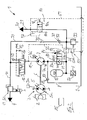
- FIG. 1 and the FIG. 2 in each case an inventive hydrostatic drive system 1 of a mobile work machine, not shown, for example, an industrial truck, shown in a schematic diagram.
- FIGS. 1 and 2 are the same components provided with the same reference numerals.
- the drive system 1 consists of an internal combustion engine 2, for example a diesel engine, a traction drive 3 of the working machine driven by the internal combustion engine 2 and a working hydraulic system 4 driven by the internal combustion engine 2.
- an internal combustion engine 2 for example a diesel engine
- a traction drive 3 of the working machine driven by the internal combustion engine 2 and a working hydraulic system 4 driven by the internal combustion engine 2.
- the traction drive 3 is formed in the illustrated embodiments as a hydrostatic drive, which consists of a variable in the delivery volume drive pump 5, which is for driving with an output shaft 6 of the engine 2 in driving connection stands.
- the drive pump 5 is connected to one or more in the intake volume fixed or adjustable, not shown hydromotors in a closed circuit in connection, which are in a manner not shown in operative connection with the driven wheels of the machine.
- the traction drive 3 may alternatively be formed as an electric traction drive with an electric generator driven by the internal combustion engine 2 and one or more electric traction motors.
- a mechanical travel drive with a mechanical transmission such as a multi-step transmission or a power split transmission or a torque converter transmission, can be provided.
- the working hydraulic system 4 includes working functions of the working machine, for example, in a truck, a working hydraulics for actuating a lifting device on a mast, for example, a linear actuator, a tilt drive and possibly existing additional consumers such as a side gate.
- the working hydraulic system 4 comprises in the illustrated embodiment at least one operated in the open circuit hydraulic pump 7, which is in driving connection with the output shaft 6 of the internal combustion engine 2 for driving.
- the hydraulic pump 7 of the working hydraulic system 4 is in the embodiments of FIGS. 1 and 2 designed as a variable displacement pump with a variable displacer volume, for example as axial piston machine in swash plate design.
- the output shaft 6 driven by the internal combustion engine 2 with the traction drive 3 driven by the output shaft 6 and with the hydraulic pump 7 of the working hydraulic system 4 driven by the output shaft 6 form a drive train of the drive system 1 according to the invention.
- the hydraulic pump 7 is the input side with the suction side by means of a suction line 8 with a container 9 in connection.
- An output side connected to the delivery side of the hydraulic pump 7 in connection conveyor line 10 is connected to a control valve means, not shown, by means of which not shown hydraulic consumers of the working hydraulic system. 4 are controllable.
- the control valve device preferably comprises one or more control way valves for actuating the consumers.
- a priority valve 12 is further shown, with which the preferred supply of a powered by the hydraulic pump 7 consumer, for example, a hydraulic steering device of the machine can be ensured.
- the priority valve 12 is connected on the input side by means of a conveying line 11 to the delivery side of the hydraulic pump 7 and is on the output side with the guided to the working hydraulic system 4 conveying line 10 and a guided to the steering conveyor line 13 in conjunction.
- the priority valve 12 is controlled by a spring 14 and the pending in a load pressure line 15 load pressure of the steering device.
- the hydraulic pump 7 is designed as a variable displacement in the variable displacement pump.
- the variable displacement pump has a position predetermined by a stop 7b with a minimum delivery volume of greater than zero cc, in which the variable displacement pump delivers a minimum delivery flow when the internal combustion engine 2 is running.
- the drive system 1 further comprises a feed circuit 20.
- the feed circuit 20 comprises a feed pressure supply line 21, to which the corresponding consumers of a feed circuit 20 are connected.
- an adjusting device 5a for adjusting the displacer volume of the drive pump 5, an adjusting 7a of the hydraulic pump 7, a feed device 3a of the hydrostatic drive, a brake system of the working machine and pilot valves for the control valves of the working hydraulic system 4 are provided.
- the drive system 1 is provided with at least one accumulator 25, which is provided to supply the supply circuit 20 with pressure medium.
- the accumulator 25 is connected for charging with pressure medium by means of a charging line 26 to the delivery line 10 of the hydraulic pump 7.
- the feed pressure supply line 21 is connected to the accumulator 25.
- the charging line 26 and the feed pressure supply line 21 are connected to a pressure medium line 30 which is connected to the delivery line 10 of the hydraulic pump 7.
- a check valve 31 is arranged, which is formed in the illustrated embodiment as in the direction of the charge line 26 and the feed pressure supply line 21 opening check valve 32.
- the pressure medium line 30 is associated with a pressure limiting valve 33 for securing the pressure in the pressure medium reservoir 25.
- a throttle device 35 is further arranged to limit the pressure medium flow flowing in the pressure medium line 30, which can be configured as a diaphragm or throttle.
- the charge line 26 and the feed pressure supply line 21 are in this case connected downstream of the check valve 31 to the pressure medium line 30.
- the pressure relief valve 33 is also connected downstream of the check valve 31 to the pressure medium line 30.
- a pressure regulating valve 40 is arranged in the feed pressure supply line 21, a pressure regulating valve 40 is arranged.
- the pressure control valve 40 is formed in the illustrated embodiment as a pressure reducing valve 41.
- the pressure control valve 40 is acted upon by a spring device 42 in the direction of a flow position 40a and actuated by the pending in the feed pressure supply line 21 feed pressure of the feed circuit 20 in the direction of a blocking position 40b.
- a control line 43 is connected to an acting in the direction of the blocking position 40b control pressure surface of the pressure control valve 40, which communicates with the feed pressure supply line 21 downstream of the pressure control valve 40 in connection.
- actuatable shut-off valve 50 is arranged in the charging line 26 a between a blocking position 50a and a flow position 50b.
- the check valve 50 is actuated by a spring means 51 in the blocking position 50a and actuated by the pending in the feed pressure supply line 21 feed pressure in the flow position 50b.
- a control line 51 which is connected to the feed pressure supply line 21 downstream of the pressure regulating valve 40, is connected to a control pressure surface of the shutoff valve 50 which acts in the direction of the flow position 50b.
- the shut-off valve 50 is designed in such a way that, when the internal combustion engine 2 is switched off and thus turned off, the shut-off valve 50 is in the blocking position 50a is actuated to avoid emptying of the accumulator 25 via the pressure control valve 40 in the feed circuit 20.
- the shut-off valve 50 is additionally electrically actuated, for example, additionally electrically operated in the blocking position 50a.
- an electrical actuator 52 is provided, for example, a solenoid.
- the check valve 50 is additionally actuated by the pending in the delivery line 11 of the pump 7 pressure in the flow position 50b.
- a control line 55 which is in communication with the delivery line 11 of the hydraulic pump 7, is connected to a control pressure surface of the shut-off valve 50 acting in the direction of the flow position 50b.
- an electrically actuated charging valve 60 is arranged, which is actuated at a control in a throttling the delivery line 10 throttle position for damming a pressure.
- the charging valve 60 is preferably designed as a retarder valve 61, which is operated in braking position of the working machine in a throttle position to impose an additional, decelerating torque on the drivingly connected to the crankshaft of the engine 2 output shaft 6 by damming a pressure in the delivery line 10, which the motor-acting torque counteracts the drive pump 5 and thus slows down the work machine.
- the pressure medium line 30 is in this case connected upstream of the charging valve 60 and thus between the charging valve 60 and the priority valve 12 to the delivery line 10.
- the accumulator 25 is further associated with a pressure sensor 27.
- the pressure sensor 27 serves to monitor the boost pressure and thus the state of charge of the accumulator 25.
- the hydraulic pump 7 of the working hydraulic system 4 is designed as Zwequadrantentriebwerk, which at the same Direction of rotation and the same direction of flow of the pressure medium as a pump and motor is operable.
- the hydraulic pump 7 sucks pressure medium from the container 9 via the suction line 8 and delivers the pressure medium via the priority valve 12 into the delivery line 10 of the working hydraulic system 4 or the delivery line 13 of the steering device.
- the hydraulic pump 7 in which the hydraulic pump 7 is designed as a hydraulic starter of a start-stop function for starting the parked internal combustion engine 2 and / or as a booster drive to support the current internal combustion engine 2, the hydraulic pump 7 on the suction side with Pressure medium from the accumulator 25 driven.
- the connection of the accumulator 25 with the suction side of the hydraulic pump 7 for the engine operation of the hydraulic pump 7 is controllable by means of an electrically actuated control valve 80.
- the control valve 80 has a blocking position 80a and a flow-through position 80b, wherein the blocking position 80a is preferably designed leakproof with a blocking in the direction of the hydraulic pump 7 check valve.
- the control valve 80 is electrically actuated and provided for this purpose with an electrical actuator 84.
- the control valve 80 is arranged in a connecting line 81, which is guided from the charging line 26 connected to the accumulator 25 to the suction line 8 led to the suction side of the hydraulic pump 7.
- the connecting line 81 is in this case connected between the shut-off valve 50 and the accumulator 25 to the charging line 26.
- check valve 82 In the suction line 8 of the hydraulic pump 7 a blocking in the direction of the container 9 check valve 82 is arranged, which is preferably designed as a blocking in the direction of the container check valve 83.
- An electronic control device 85 is on the input side to the pressure sensor 27 in connection and serves to control the charging valve 60 and the electrically actuated control valve 80.
- the electronic control device 85 continues to serve in the embodiment of the FIG. 1 for controlling the electrical actuating device 52 of the shut-off valve 50.
- the accumulator 25 can be charged in a simple manner upon actuation of a consumer of the working hydraulic system 4 with pressure medium, provided that the load pressure of the consumer exceeds the boost pressure of the accumulator 25.
- the charging valve 60 in a throttle position of the accumulator 25 can be charged in a simple manner in operating conditions in which the engine has 2 power reserves. If the charging valve 60 is designed as a retarder valve 61 and is operated in braking position of the working machine in a throttle position, the kinetic energy of the decelerating machine is used to load the accumulator 25 and there is an energy recovery.
- the drive pump 5 operates as a motor which drives the hydraulic pump 7 of the working hydraulic system 4, so that via the driven in the direction of throttle position retarder valve 61 of the accumulator 25 can be charged with pressure medium.
- the hydraulic pump 7 thus promotes a flow for actuation of the consumers of the working hydraulic system 4 for controlled consumers of the working hydraulic system 4 and also serves to supply a flow for loading the accumulator 25.
- the hydraulic pump 7 on the primary side by the supplied from the engine 2 Power to be driven.
- the hydraulic pump 7 is driven to charge the accumulator 25 with the recorded during deceleration of the machine in a braking operation kinetic energy of the machine, so that the accumulator 25 is charged rekuperativ when braking the machine with pressure medium.
- Corresponding operating strategies for loading the pressure medium store 25 are stored in the electronic control device 85.
- the supply circuit 20 is required by means of the pressure control valve 40 with pressure medium from the accumulator 25th provided.
- the pressure control valve 40 By means of the pressure control valve 40, only the pressure fluid quantity which corresponds to the supply quantity requirement of the supply circuit 20 is taken from the pressure medium reservoir 25.
- the position of the hydraulic pump 7 with a minimum delivery volume of greater than zero makes it possible for the required feed pressure in the supply circuit 20 to be made available immediately when a deactivated internal combustion engine 2 is started.
- the accumulator 25 is decoupled from the pressure medium line 30 by means of the actuated in the blocking position 50a check valve 50 so that the supply circuit 20 is supplied via the delivery line 10 from the hydraulic pump 7 with pressure medium.
- the operated in the blocking position 50a check valve 50 thus makes it possible to prioritize the supply of the supply circuit 20 before the loading operation of the accumulator 25 until the feed pressure is generated in the supply circuit 20. It is thereby achieved that, immediately after the start of the parked internal combustion engine 2, the feed pressure of the supply circuit 20 is generated by the running hydraulic pump 7, which can be used to actuate the adjusting device 7a of the hydraulic pump 7.
- the shut-off valve 50 is automatically actuated by the pending in the feed circuit 20 feed pressure in the flow position 50a, so that in the invention by means of both the pressure control valve 40, the control of the feed pressure in the feed circuit 20 and by means of the shut-off valve 50, the switching off of the pressure medium reservoir 25sregelnd without external control is functional.
- shut-off valve 50 In order to avoid a discharge of the accumulator 25 with the internal combustion engine 2 and thus shut down working machine, is in the FIG. 1 operated by the control device 85 by means of the actuator 52, the shut-off valve 50 in the blocking position 50a or in the FIG. 2 in the absence of delivery pressure of the hydraulic pump 7, the shut-off valve 50 is actuated by the spring device 51 in the blocking position 50a.
- the drive system 1 according to the invention has a number of advantages.
- the drive system 1 according to the invention has no supply pressure pump for supplying the supply circuit 20. This allows the inventive Drive system 1 a short installation length of the drive train. The elimination of the feed pump continues to result in a cost savings.
- the need-based provision of the supply quantity requirement and the feed pressure of the feed circuit 20 from the accumulator 25 results in a fuel saving of the internal combustion engine 2.
- the fuel consumption of the internal combustion engine 2 can be further reduced when the loading of the accumulator 25 with recuperated energy.
- a reduction in the starting torque of the internal combustion engine 2 can furthermore be achieved by the provision according to the invention of the supply quantity requirement and the feed pressure.
- the boost pressure of the accumulator 25 can be reduced, so that there are small throttling losses at the pressure control valve 40.
- a pressure medium storage 25 one or more pressure medium reservoir 25 can be used. In the case of several pressure medium stores, the individual pressure medium stores can be charged at different pressure levels. This makes it possible, depending on the consumer and consumer pressure to use the appropriate pressure fluid reservoir 25 to supply the consumer.
- a pressure medium accumulator 25 charged to a low pressure can be used.
- a pressure medium reservoir 25 charged to a high pressure can be used.
- a corresponding operating strategy is deposited, which makes it possible that the accumulator 25 despite a removal of a pressure medium quantity for supplying the supply circuit 20 is always sufficiently charged and filled to a start of the engine 2 by a motor operation of the hydraulic pump 7 permit, in which the hydraulic pump 7 is driven with pressure medium from the accumulator 25.
Landscapes
- Engineering & Computer Science (AREA)
- Transportation (AREA)
- Chemical & Material Sciences (AREA)
- Combustion & Propulsion (AREA)
- Mechanical Engineering (AREA)
- Structural Engineering (AREA)
- Civil Engineering (AREA)
- Life Sciences & Earth Sciences (AREA)
- Geology (AREA)
- Fluid-Pressure Circuits (AREA)
- Auxiliary Drives, Propulsion Controls, And Safety Devices (AREA)
Abstract
Description
- Die Erfindung betrifft ein hydrostatisches Antriebssystem einer mobilen Arbeitsmaschine, insbesondere eines Flurförderzeugs, mit einem Verbrennungsmotor und einem von dem Verbrennungsmotor angetriebenen Arbeitshydrauliksystem, wobei das Arbeitshydrauliksystem mindestens eine von dem Verbrennungsmotor angetriebene Hydraulikpumpe aufweist, wobei die Hydraulikpumpe mit einer Saugseite Druckmittel aus einem Behälter ansaugt und in eine zu dem Arbeitshydrauliksystem geführte Förderleitung fördert, und wobei das Antriebssystem einen Speisekreis aufweist und mit mindestens einem Druckmittelspeicher versehen ist.
- Hydrostatische Antriebssysteme von mobilen Arbeitsmaschinen, beispielsweise Flurförderzeuge, weisen einen hydraulischen Speisekreis auf, in dem ein im Wesentlichen konstanter Speisedruck ansteht, um die Verbraucher des Speisekreises mit Druckmittel zu versorgen. Bei bekannten hydrostatischen Antriebssystemen wird zur Versorgung des Speisekreises mit Druckmittel eine als Konstantpumpe ausgebildete Speisepumpe eingesetzt, die von dem Verbrennungsmotor der Arbeitsmaschine angetrieben ist und auf einem von dem Verbrennungsmotor angetriebenen Antriebsstrang montiert ist. Eine als Konstantpumpe ausgebildete Speisepumpe liefert aufgrund eines festen und konstanten Fördervolumens eine Fördermenge, die sich aus dem konstanten Fördervolumen der Speisepumpe und der Drehzahl des Verbrennungsmotors ergibt. Die Drehzahl des Verbrennungsmotors wird hierbei von den angeforderten Arbeitsfunktionen des Arbeitshydrauliksystems und/oder eines Fahrantriebs der Arbeitsmaschine bestimmt. Bei bekannten hydrostatischen Antriebssystemen folgt somit die von der Speisepumpe gelieferte Fördermenge nicht dem Bedarf des Speisekreises, sondern der sich aus der angeforderten Arbeitsfunktion erforderlichen Drehzahl des Verbrennungsmotors. Das Fördervolumen der als Konstantpumpe ausgebildeten Speisepumpe wird bei bekannten Antriebssystemen derart ausgelegt, dass bei minimaler Drehzahl des Verbrennungsmotors die Speisepumpe den maximalen möglichen Speisemengenbedarf des Speisekreises zur Verfügung stellt. Durch diese Auslegung der als Konstantpumpe ausgebildeten Speisepumpe entstehen bei höheren Drehzahlen des Verbrennungsmotors Überkapazitäten, wobei die über den Speisemengenbedarf des Speisekreises hinausgehende Fördermenge der Speisepumpe an einem Druckbegrenzungsventil, das auf den maximalen Speisedruck eingestellt wird, abgedrosselt wird. Durch das Abdrosseln der über den Speisemengenbedarf des Speisekreises hinausgehenden Fördermenge der als Konstantpumpe ausgebildeten Speisepumpe bei bekannten Antriebssystemen ergibt sich ein erhöhter Kraftstoffverbrauch des Verbrennungsmotors und ein erhöhter Wärmeeintrag in das Druckmittel des Antriebssystems.
- Ein gattungsgemäßes Antriebssystem mit einer als Konstantpumpe ausgebildete Speisepumpe ist aus der
DE 10 2011 104 919 A1 bekannt. Bei dem aus derDE 10 2011 104 919 A1 bekannten Antriebssystem ist weiterhin ein Druckmittelspeicher vorgesehen, der einen zusätzlichen, im Antriebsstrang angeordneten Hydromotor des Antriebssystems antreibt, um über den Hydromotor einen hydraulischen Starter zum Starten des laufenden Verbrennungsmotors zur Verfügung zu stellen und/oder über den Hydromotor einen Booster-Antrieb zur Verfügung zu stellen, der bei laufendem Verbrennungsmotor ein zusätzliches Drehmoment in den Antriebsstrang einleitet. - Bei bekannten Antriebssystemen, bei denen die Speisepumpe zusammen mit einem Fahrantrieb und der Hydraulikpumpe des Arbeitshydrauliksystems auf dem Antriebsstrang angeordnet ist, ergibt sich eine große Baulänge des Antriebsstranges. Insbesondere bei mobilen Arbeitsmaschinen, bei denen der Antriebsstrang in Fahrzeugquerrichtung eingebaut ist, kann die Baulänge des Antriebsstranges zu Einbauproblemen in der Arbeitsmaschine führen.
- Sofern die Speisepumpe starr, d.h. ohne lösbare Kupplungseinrichtung, auf einer Antriebswelle des Antriebsstrangs angeordnet ist, wird durch die Speisepumpe weiterhin das Startdrehmoment erhöht, das zum Starten des abgestellten Verbrennungsmotors erforderlich ist. Insbesondere bei einem Kaltstart unter kalten Umgebungsbedingungen kann es hierbei zu Startproblemen des abgestellten Verbrennungsmotors kommen, wobei der Verbrennungsmotor nicht anspringen kann oder ein elektrischer Anlasser des Verbrennungsmotors durch Überlastung versagen kann.
- Weiterhin erhöht sich durch die erforderliche zusätzliche Speisepumpe der Herstellungsaufwand des Antriebssystems.
- Der vorliegenden Erfindung liegt die Aufgabe zugrunde, ein Antriebssystem der eingangs genannten Gattung zur Verfügung zu stellen, das einen geringen Bauaufwand und einen geringen Bauraumbedarf für die Versorgung des Speisekreises mit Druckmittel aufweist.
- Diese Aufgabe wird erfindungsgemäß dadurch gelöst, dass der Druckmittelspeicher zur Versorgung des Speisekreises mit Druckmittel vorgesehen ist, wobei der Druckmittelspeicher zum Laden mit Druckmittel mittels einer Ladeleitung an die Förderleitung der Hydraulikpumpe angeschlossen ist und zur Versorgung des Speisekreises eine Speisedruckversorgungsleitung an den Druckmittelspeicher angeschlossen ist, wobei in der Speisedruckversorgungsleitung ein Druckregelventil, insbesondere ein Druckminderventil, und in der Ladeleitung ein zwischen einer Sperrstellung und einer Durchflussstellung betätigbares Absperrventil angeordnet ist. Erfindungsgemäß dient somit der Druckmittelspeicher zur Versorgung des Speisekreises, wobei mittels des Druckregelventils, beispielsweise einem Druckminderventil, bedarfsgerecht die zur Versorgung der Verbraucher des Speiskreises tatsächlich erforderliche Druckmittelmenge aus dem Druckmittelspeicher entnommen wird. Ein Druckregelventil, wobei der Druckmittelspeicher unter Zwischenschaltung des Druckregelventils an den Speisekreis angeschlossen ist, ermöglicht es auf einfache Weise, den Druck im Speisekreis auf einen minimalen Speisedruck zu regeln und den Druckmittelbedarf des Speisekreises bedarfsgerecht aus dem Druckmittelspeicher zu entnehmen. Sofern im Speisekreis der Einstelldruck des Druckregelventils erreicht ist, wird das Druckregelventil in eine Schließstellung beaufschlagt, so dass dem Druckmittelspeicher kein weiteres Druckmittel zur Versorgung des Speisekreises entnommen wird. Sofern der Druck im Speisekreis bei angesteuerten Verbrauchern des Speisekreises unter den Einstelldruck des Druckregelventils absinkt, wird das Druckregelventil in eine Öffnungsstellung beaufschlagt, so dass Druckmittel aus dem Druckmittelspeicher zur Versorgung des Speisekreises entnommen wird. Durch die bedarfsgerechte Versorgung des Speisekreises mit Druckmittel unter Speisedruck aus dem Druckmittelspeicher wird eine Kraftstoffeinsparung des Verbrennungsmotors erzielt. Zudem wird die Erwärmung des Druckmittels des Antriebssystems verringert. Zum Laden des Druckmittelspeichers ist der Druckmittelspeicher an die Förderleitung der Hydraulikpumpe des Arbeitshydrauliksystems anschließbar. Das erfindungsgemäße Antriebssystem benötigt somit zur Versorgung des Speisekreises keine zusätzliche Speisepumpe. Durch den Entfall der Speisepumpe weist das erfindungsgemäße Antriebssystem einen geringen Bauaufwand und eine geringen Bauraumbedarf auf, wobei die Baulänge des Antriebsstranges verringert werden kann. Zudem kann durch den Entfall der Speisepumpe bei dem erfindungsgemäßen Antriebssystem eine Verringerung des Startdrehmoments des Verbrennungsmotors erzielt werden, insbesondere bei einem Kaltstart des Verbrennungsmotors bei kalten Umgebungsbedingungen. Das Absperrventil ermöglicht es, in bestimmten Betriebssituationen, beispielsweise beim Start des Verbrennungsmotors, die Verbindung der Ladeleitung abzusperren, wodurch eine weitere Verringerung des Startdrehmoments des Verbrennungsmotors erzielbar ist.
- Mit besonderem Vorteil sind gemäß einer Ausführungsform der Erfindung die Ladeleitung und die Speisedruckversorgungsleitung an eine Druckmittelleitung angeschlossen, die mit der Förderleitung der Hydraulikpumpe verbunden ist. Hierdurch wird ein Laden des Druckmittelspeichers mit Druckmittel aus der Förderleitung der Hydraulikpumpe erzielt und weiterhin ermöglicht, dass der Speisekreis mit Druckmittel aus dem Druckmittelspeicher oder mit Druckmittel aus der Förderleitung der Hydraulikpumpe versorgt werden kann, beispielsweise falls der Druckmittelspeicher keinen ausreichenden Ladedruck aufweisen sollte.
- Gemäß einer Ausführungsform der Erfindung ist das Absperrventil von einer Federeinrichtung in die Sperrstellung betätigt und von dem in der Speisedruckversorgungsleitung anstehenden Speisedruck des Speisekreises in die Durchflussstellung betätigt. Hierdurch wird erzielt, dass bei einem drucklosen Druckmittelspeicher das in der Ladeleitung angeordnete Absperrventil in die Sperrstellung betätigt wird, so dass die Versorgung des Speisekreises mit Druckmittel aus der Förderleitung der Hydraulikpumpe priorisiert wird. Hierdurch wird insbesondere nach einem Start des abgestellten Verbrennungsmotors auf einfache Weise erzielt, dass zeitlich unmittelbar nach dem Startvorgang des Verbrennungsmotors in dem Speisekreis ein Speisedruck ansteht, der eine Versorgung der Verbraucher des Speisekreises ermöglicht. Das Absperrventil wird durch den in der Speisedruckversorgungsleitung anstehenden Speisedruck selbstregulierend in die Öffnungsstellung angesteuert, sobald ein ausreichender Speisedruck im Speisekreis vorhanden ist. In Verbindung mit dem Druckregelventil, das den Speisedruck selbstregulierend regelt, wird somit ebenfalls mit dem Absperrventil eine selbstregelnde Wegschaltung des Druckmittelspeichers von dem Speisekreis erzielt.
- Gemäß einer Ausführungsform der Erfindung ist das Absperrventil bei abgeschaltetem Verbrennungsmotor in die Sperrstellung betätigt. Sofern das Absperrventil bei abgestelltem Verbrennungsmotor in die Sperrstellung betätigt ist, kann ein Entleeren und somit eine Entladen des Druckmittelspeichers in den Speisekreis, beispielsweise aufgrund von Leckagen im Speisekreis, über das Druckregelventil bei abgestelltem Verbrennungsmotor auf einfache Weise verhindert werden.
- Gemäß einer Ausführungsform der Erfindung ist das Absperrventil elektrisch betätigbar und steht zur Ansteuerung mit einer elektronischen Steuereinrichtung in Wirkverbindung, wobei die elektronische Steuereinrichtung derart ausgebildet ist, dass bei abgeschaltetem Verbrennungsmotor das Absperrventil in die Sperrstellung betätigt ist. Hierdurch kann auf einfache Weise erzielt werden, das Absperrventil bei abgeschaltetem Verbrennungsmotor in die Sperrstellung zu betätigen.
- Gemäß einer alternativen Ausführungsform der Erfindung ist das Absperrventil von dem in der Förderleitung der Pumpe anstehenden Druck in die Durchflussstellung betätigt. Das Absperrventil ist somit in die Durchflussstellung von dem Förderdruck der Pumpe und dem in der Speisedruckversorgungsleitung anstehenden Speisedruck in die Durchflussstellung betätigt. Hierdurch kann ebenfalls auf einfache Weise erzielt werden, dass das Absperrventil bei abgeschaltetem Verbrennungsmotor, wobei die Hydraulikpumpe keinen Förderdruck erzeugt, von der Federeinrichtung in die Sperrstellung betätigt ist. Die Ansteuerung des Absperrventils erfolgt somit rein hydraulisch, in dem der Abfall des Förderdruckes an der Hydraulikpumpe als Steuersignals verwendet wird, um das Absperrventil bei abgeschaltetem Verbrennungsmotor in die Sperrstellung betätigen zu können.
- Mit einer vorteilhaften Ausführungsform der Erfindung ist die Hydraulikpumpe als im Verdrängervolumen verstellbare Verstellpumpe ausgebildet, wobei sich die Verstellpumpe beim Start des Verbrennungsmotor in einer Stellung befindet, in der die Verstellpumpe bei laufendem Verbrennungsmotor einen Förderstrom liefert. Hierdurch wird auf einfache Weise erzielt, dass nach dem Start des abgestellten Verbrennungsmotors die Verstellpumpe einen Förderstrom liefert, um den erforderlichen Speisedruck im Speisekreis zu erzeugen. Die Verstellpumpe kann sich hierbei beim Start des Verbrennungsmotors in einer Stellung mit einem minimalen Fördervolumen von ungleich Null befinden, bei dem die Verstellpumpe einen minimalen Förderstrom liefert. Sofern die Verstellpumpe als hydraulischer Starter des abgestellten Verbrennungsmotors eingesetzt wird, kann sich die Verstellpumpe zum Start des Verbrennungsmotors auch in einer Stellung mit maximalen Fördervolumen befinden, um ein entsprechend hohes Drehmoment zum Starten des Verbrennungsmotors bereit zu stellen.
- In einer vorteilhaften Weiterbildung der Erfindung ist die Hydraulikpumpe als Pumpe und Motor betreibbar, wobei die Hydraulikpumpe im Pumpenbetrieb mit der Saugseite Druckmittel aus dem Behälter ansaugt und in die zu dem Arbeitshydrauliksystem geführte Förderleitung fördert und wobei der Hydraulikpumpe im Motorbetrieb an der Saugseite Druckmittel aus dem Druckmittelspeicher zuführbar ist.
- Mit einer derartigen als Pumpe und Motor betreibbaren Hydraulikpumpe ist es auf einfache Weise möglich, die Hydraulikpumpe im Motorbetrieb als hydraulischen Starter zum Starten des Verbrennungsmotors bei einer Start-Stopp-Funktion und/oder als Booster-Antrieb zur Unterstützung des laufenden Verbrennungsmotors zu verwenden.
- Der Druckmittelspeicher kann mittels einer geeigneten Ladeschaltung von der Hydraulikpumpe des Arbeitshydrauliksystems mit Druckmittel aufgeladen werden. Besondere Vorteile sind erzielbar, wenn gemäß einer Weiterbildung der Erfindung der Druckmittelspeicher im Bremsbetrieb eines Fahrantriebs der Arbeitsmaschine und/oder im Senkenbetrieb eines Hubantriebs des Arbeitshydrauliksystems und/oder im Bremsbetrieb eines Drehantriebs, beispielsweise eines Drehwerksantriebs, der Arbeitsmaschine mit Druckmittel aufladbar ist. Hierdurch kann eine Rekuperation und somit eine Rückgewinnung von Energie erfolgen und der Druckmittelspeicher mit freiwerdender Energie, beispielsweise im Bremsbetrieb des Fahrantriebs und/oder im Senkenbetrieb eines Hubantriebs des Arbeitshydrauliksystems und/oder im Bremsbetrieb eines Drehantriebs, aufgeladen werden. Hierdurch wird eine weitere Kraftstoffeinsparung des Verbrennungsmotors erzielt, da zum Laden des Druckmittelspeichers keine Energie von dem Verbrennungsmotor bereit gestellt werden muss und über die Versorgung des Speisekreises mit Druckmittel aus dem Druckmittelspeicher eine Versorgung des Speisekreises und Bereitstellung des Speisedruckes im Speisekreis mit zurückgewonnener Energie erzielt wird.
- Der Speisekreis weist gemäß einer bevorzugten Ausgestaltungsform der Erfindung einen oder mehrere der folgenden Verbraucher auf:
- eine Verstelleinrichtung zur Verstellung des Verdrängervolumens der Hydraulikpumpe,
- eine Verstelleinrichtung zur Verstellung des Verdrängervolumens einer hydrostatischen Verstellpumpe und/oder eine Verstelleinrichtung eines hydrostatischen Verstellmotors eines hydrostatischen Fahrantriebs des Antriebssystems,
- eine Einspeisevorrichtung des hydrostatischen Fahrantriebs,
- eine hydraulische Bremsanlage der Arbeitsmaschine,
- Vorsteuerventile für die Steuerwegeventile des Arbeitshydrauliksystems.
- Weitere Vorteile und Einzelheiten der Erfindung werden anhand des in der schematischen Figur dargestellten Ausführungsbeispiels näher erläutert. Hierbei zeigt
- Figur 1
- den Schaltplan einer ersten Ausführungsform der Erfindung und
- Figur 2
- den Schaltplan einer zweiten Ausführungsform der Erfindung.
- In der
Figur 1 und derFigur 2 ist jeweils ein erfindungsgemäßes hydrostatisches Antriebssystem 1 einer nicht näher dargestellten mobilen Arbeitsmaschine, beispielsweise eines Flurförderzeugs, in einer Prinzipdarstellung dargestellt. In denFiguren 1 und2 sind gleiche Bauteile mit gleichen Bezugsziffern versehen. - Der erfindungsgemäße Antriebssystem 1 besteht aus einem Verbrennungsmotor 2, beispielsweise einem Dieselmotor, einem von dem Verbrennungsmotor 2 angetriebenen Fahrantrieb 3 der Arbeitsmaschine sowie einem von dem Verbrennungsmotor 2 angetriebenen Arbeitshydrauliksystem 4.
- Der Fahrantrieb 3 ist in den dargestellten Ausführungsbeispielen als hydrostatischer Fahrantrieb ausgebildet, der aus einer im Fördervolumen verstellbaren Fahrpumpe 5 besteht, die zum Antrieb mit einer Abtriebswelle 6 des Verbrennungsmotors 2 in trieblicher Verbindung steht. Die Fahrpumpe 5 steht mit einem oder mehreren im Schluckvolumen festen oder verstellbaren, nicht näher dargestellten Hydromotoren im geschlossenen Kreislauf in Verbindung, die auf nicht mehr dargestellte Weise mit den angetriebenen Rädern der Arbeitsmaschine in Wirkverbindung stehen.
- Der Fahrantrieb 3 kann alternativ als elektrischer Fahrantrieb mit einem von dem Verbrennungsmotor 2 angetriebenen elektrischen Generator und einem oder mehreren elektrischen Fahrmotoren gebildet werden. Zudem kann als Fahrantrieb ein mechanischer Fahrantrieb mit einem mechanischen Getriebe, beispielsweise einem Stufenschaltgetriebe oder einem Leistungsverzweigungsgetriebe oder einem Drehmomentwandlergetriebe, vorgesehen werden.
- Das Arbeitshydrauliksystem 4 umfasst Arbeitsfunktionen der Arbeitsmaschine, beispielsweise bei einem Flurförderzeug eine Arbeitshydraulik zum Betätigen eines Lastaufnahmemittels an einem Hubmast, beispielsweise einen Hubantrieb, einen Neigeantrieb und gegebenenfalls vorhandene Zusatzverbraucher wie einen Seitenschieber.
- Das Arbeitshydrauliksystem 4 umfasst im dargestellten Ausführungsbeispiel mindestens eine im offenen Kreislauf betriebene Hydraulikpumpe 7, die zum Antrieb mit der Abtriebswelle 6 des Verbrennungsmotors 2 in trieblicher Verbindung steht. Die Hydraulikpumpe 7 des Arbeitshydrauliksystems 4 ist in den Ausführungsbeispielen der
Figuren 1 und2 als Verstellpumpe mit einem veränderbaren Verdrängervolumen ausgebildet, beispielsweise als Axialkolbenmaschine in Schrägscheibenbauweise. - Die von dem Verbrennungsmotor 2 angetriebene Abtriebswelle 6 mit dem von der Abtriebswelle 6 angetriebenen Fahrantrieb 3 und mit der von der Abtriebswelle 6 angetriebenen Hydraulikpumpe 7 des Arbeitshydrauliksystems 4 bilden einen Antriebsstrang des erfindungsgemäßen Antriebssystems 1.
- Die Hydraulikpumpe 7 steht eingangsseitig mit der Saugseite mittels einer Ansaugleitung 8 mit einem Behälter 9 in Verbindung. Eine ausgangsseitig mit der Förderseite der Hydraulikpumpe 7 in Verbindung stehende Förderleitung 10 ist an eine nicht näher dargestellte Steuerventileinrichtung angeschlossen, mittels der die nicht näher dargestellten hydraulischen Verbraucher des Arbeitshydrauliksystems 4 steuerbar sind. Die Steuerventileinrichtung umfasst bevorzugt ein oder mehrere Steuerwegeventile zur Betätigung der Verbraucher. Im dargestellten Ausführungsbeispiel ist weiterhin ein Prioritätsventil 12 dargestellt, mit dem die bevorzugte Versorgung eines von der Hydraulikpumpe 7 versorgten Verbrauchers, beispielsweise einer hydraulischen Lenkungseinrichtung der Arbeitsmaschine, sichergestellt werden kann. Das Prioritätsventil 12 ist eingangsseitig mittels einer Förderleitung 11 mit der Förderseite der Hydraulikpumpe 7 verbunden und steht ausgangsseitig mit der zu dem Arbeitshydrauliksystem 4 geführten Förderleitung 10 sowie einer zu der Lenkungseinrichtung geführten Förderleitung 13 in Verbindung. Das Prioritätsventil 12 ist von einer Feder 14 sowie dem in einer Lastdruckleitung 15 anstehenden Lastdruck der Lenkungseinrichtung gesteuert.
- Die Hydraulikpumpe 7 ist als im Verdrängervolumen verstellbare Verstellpumpe ausgebildet. Die Verstellpumpe weist eine von einem Anschlag 7b vorgegebene Stellung mit minimalem Fördervolumen von größer Null ccm auf, in dem die Verstellpumpe bei laufendem Verbrennungsmotor 2 einen minimalen Förderstrom liefert.
- Das Antriebssystem 1 umfasst weiterhin einen Speisekreis 20. Der Speisekreis 20 umfasst eine Speisedruckversorgungsleitung 21, an die die entsprechenden Verbraucher eines Speisekreises 20 angeschlossen sind. Als Verbraucher des Speisekreises 20 sind eine Verstelleinrichtung 5a zur Verstellung des Verdrängervolumens der Fahrpumpe 5, eine Verstelleinrichtung 7a der Hydraulikpumpe 7, eine Einspeisevorrichtung 3a des hydrostatischen Fahrantriebs, eine Bremsanlage der Arbeitsmaschine und Vorsteuerventile für die Steuerwegeventile des Arbeitshydrauliksystems 4 vorgesehen.
- Das erfindungsgemäße Antriebssystem 1 ist mit mindestens einem Druckmittelspeicher 25 versehen, der zur Versorgung des Speisekreises 20 mit Druckmittel vorgesehen ist. Der Druckmittelspeicher 25 ist zum Laden mit Druckmittel mittels einer Ladeleitung 26 an die Förderleitung 10 der Hydraulikpumpe 7 angeschlossen. Zur Versorgung des Speisekreises 20 mit Druckmittel aus dem Druckmittelspeicher 25 ist die Speisedruckversorgungsleitung 21 an den Druckmittelspeicher 25 angeschlossen.
- Im dargestellten Ausführungsbeispiel sind die Ladeleitung 26 und die Speisedruckversorgungsleitung 21 an eine Druckmittelleitung 30 angeschlossen, die mit der Förderleitung 10 der Hydraulikpumpe 7 verbunden ist. In der Druckmittelleitung 30 ist ein Sperrventil 31 angeordnet, das im dargestellten Ausführungsbeispiel als in Richtung zur Ladeleitung 26 und zur Speisedruckversorgungsleitung 21 öffnendes Rückschlagventil 32 ausgebildet ist. Weiterhin ist der Druckmittelleitung 30 ein Druckbegrenzungsventil 33 zur Absicherung des Druckes in dem Druckmittelspeicher 25 zugeordnet. In der Druckmittelleitung 30 ist weiterhin zur Begrenzung des in der Druckmittelleitung 30 strömenden Druckmittelvolumenstroms eine Drosseleinrichtung 35 angeordnet, die als Blende oder Drossel ausgeführt sein kann. Die Ladeleitung 26 und die Speisedruckversorgungsleitung 21 sind hierbei stromab des Sperrventils 31 an die Druckmittelleitung 30 angeschlossen. Das Druckbegrenzungsventil 33 ist ebenfalls stromab des Sperrventils 31 an die Druckmittelleitung 30 angeschlossen.
- In der Speisedruckversorgungsleitung 21 ist ein Druckregelventil 40 angeordnet. Das Druckregelventil 40 ist im dargestellten Ausführungsbeispiel als Druckminderventil 41 ausgebildet. Das Druckregelventil 40 ist von einer Federeinrichtung 42 in Richtung einer Durchflussstellung 40a beaufschlagt und von dem in der Speisedruckversorgungsleitung 21 anstehenden Speisedruck des Speisekreises 20 in Richtung einer Sperrstellung 40b betätigt. Hierzu ist an eine in Richtung der Sperrstellung 40b wirkende Steuerdruckfläche des Druckregelventils 40 eine Steuerleitung 43 angeschlossen, die mit der Speisedruckversorgungsleitung 21 stromab des Druckregelventils 40 in Verbindung steht.
- In der Ladeleitung 26 ist ein zwischen einer Sperrstellung 50a und einer Durchflussstellung 50b betätigbares Absperrventil 50 angeordnet. Das Absperrventil 50 ist von einer Federeinrichtung 51 in die Sperrstellung 50a betätigt und von dem in der Speisedruckversorgungsleitung 21 anstehenden Speisedruck in die Durchflussstellung 50b betätigt. Hierzu ist an eine in Richtung der Durchflussstellung 50b wirkende Steuerdruckfläche des Absperrventils 50 eine Steuerleitung 51 angeschlossen, die mit der Speisedruckversorgungsleitung 21 stromab des Druckregelventils 40 verbunden ist.
- Das Absperrventil 50 ist derart ausgebildet, dass bei abgeschaltetem und somit abgestelltem Verbrennungsmotor 2 das Absperrventil 50 in die Sperrstellung 50a betätigt ist, um ein Entleeren des Druckmittelspeichers 25 über das Druckregelventil 40 in den Speisekreis 20 zu vermeiden.
- In dem Ausführungsbeispiel der
Figur 1 ist hierzu das Absperrventil 50 zusätzlich elektrisch betätigbar, beispielsweise zusätzlich elektrisch in die Sperrstellung 50a betätigbar. Zur elektrischen Betätigung des Absperrventils 50 ist eine elektrische Betätigungseinrichtung 52 vorgesehen, beispielsweise ein Schaltmagnet. - In dem Ausführungsbeispiel der
Figur 2 , das sich von derFigur 1 nur durch die Ansteuerung des Absperrventils 50 unterscheidet, ist hierzu das Absperrventil 50 zusätzlich von dem in der Förderleitung 11 der Pumpe 7 anstehenden Druck in die Durchflussstellung 50b betätigt ist. Hierzu ist an eine in Richtung der Durchflussstellung 50b wirkende Steuerdruckfläche des Absperrventils 50 eine Steuerleitung 55 angeschlossen, die mit der Förderleitung 11 der Hydraulikpumpe 7 in Verbindung steht. - In der Förderleitung 10 ist ein elektrisch betätigbares Ladeventil 60 angeordnet, das bei einer Ansteuerung in eine die Förderleitung 10 drosselnde Drosselstellung zum Aufstauen eines Druckes betätigbar ist. Das Ladeventil 60 ist bevorzugt als Retarderventil 61 ausgeführt, das im Bremsbetrieb der Arbeitsmaschine in eine Drosselstellung betätigt wird, um durch Aufstauen eines Druckes in der Förderleitung 10 ein zusätzliches, abbremsendes Drehmoment an der mit der Kurbelwelle des Verbrennungsmotors 2 trieblich verbundenen Abtriebswelle 6 aufzuprägen, welches dem motorisch wirkenden Drehmoment an der Fahrpumpe 5 entgegenwirkt und so die Arbeitsmaschine abbremst. Die Druckmittelleitung 30 ist hierbei stromauf des Ladeventils 60 und somit zwischen dem Ladeventil 60 und dem Prioritätsventil 12 an die Förderleitung 10 angeschlossen.
- Dem Druckmittelspeicher 25 ist weiterhin ein Drucksensor 27 zugeordnet. Der Drucksensor 27 dient zur Überwachung des Ladedruckes und somit des Ladezustands des Druckmittelspeichers 25.
- Bei dem erfindungsgemäßen Antriebsstrang 1 ist die Hydraulikpumpe 7 des Arbeitshydrauliksystems 4 als Zweiquadrantentriebwerk ausgebildet, das bei gleicher Drehrichtung und gleicher Durchflussrichtung des Druckmittels als Pumpe und Motor betreibbar ist.
- Im Pumpenbetrieb saugt die Hydraulikpumpe 7 über die Ansaugleitung 8 Druckmittel aus dem Behälter 9 an und fördert das Druckmittel über das Prioritätsventil 12 in die Förderleitung 10 des Arbeitshydrauliksystems 4 bzw. die Förderleitung 13 der Lenkungseinrichtung. Im Motorbetrieb der Hydraulikpumpe 7, in der die Hydraulikpumpe 7 als hydraulischer Starter einer Start-Stopp-Funktion zum Starten des abgestellten Verbrennungsmotors 2 und/oder als Booster-Antrieb zur Unterstützung des laufenden Verbrennungsmotors 2 ausgebildet ist, wird die Hydraulikpumpe 7 an der Saugseite mit Druckmittel aus dem Druckmittelspeicher 25 angetrieben.
- Die Verbindung des Druckmittelspeichers 25 mit der Saugseite der Hydraulikpumpe 7 für den Motorbetrieb der Hydraulikpumpe 7 ist mittels eines elektrisch betätigbaren Steuerventils 80 steuerbar. Das Steuerventil 80 weist eine Sperrstellung 80a und eine Durchflussstellung 80b auf, wobei die Sperrstellung 80a bevorzugt leckagedicht ausgeführt ist mit einem in Richtung zur Hydraulikpumpe 7 sperrenden Sperrventil. Das Steuerventil 80 ist elektrisch betätigbar und hierzu mit einer elektrischen Betätigungseinrichtung 84 versehen.
- Das Steuerventil 80 ist in einer Verbindungsleitung 81 angeordnet, die von der mit dem Druckmittelspeicher 25 verbundenen Ladeleitung 26 zu der zur Saugseite der Hydraulikpumpe 7 geführten Ansaugleitung 8 geführt ist. Die Verbindungsleitung 81 ist hierbei zwischen dem Absperrventil 50 und dem Druckmittelspeicher 25 an die Ladeleitung 26 angeschlossen.
- In der Ansaugleitung 8 der Hydraulikpumpe 7 ist ein in Richtung zum Behälter 9 sperrendes Sperrventil 82 angeordnet, das bevorzugt als ein in Richtung zum Behälter sperrendes Rückschlagventil 83 ausgebildet ist.
- Eine elektronische Steuereinrichtung 85 steht eingangsseitig mit dem Drucksensor 27 in Verbindung und dient zur Ansteuerung des Ladeventils 60 sowie des elektrisch betätigbaren Steuerventils 80. Die elektronische Steuereinrichtung 85 dient weiterhin in dem Ausführungsbeispiel der
Figur 1 zur Ansteuerung der elektrischen Betätigungseinrichtung 52 des Absperrventils 50. - Bei dem erfindungsgemäßen Antriebssystem 1 kann der Druckmittelspeicher 25 auf einfache Weise bei einer Betätigung eines Verbrauchers des Arbeitshydrauliksystems 4 mit Druckmittel aufgeladen werden, sofern der Lastdruck des Verbrauchers den Ladedruck des Druckmittelspeichers 25 übersteigt. Zudem kann durch entsprechende Ansteuerung des Ladeventils 60 in eine Drosselstellung der Druckmittelspeicher 25 auf einfache Weise in Betriebszuständen aufgeladen werden, in denen der Verbrennungsmotor 2 Leistungsreserven aufweist. Sofern das Ladeventil 60 als Retarderventil 61 ausgeführt ist und im Bremsbetrieb der Arbeitsmaschine in eine Drosselstellung betätigt wird, wird zum Laden des Druckmittelspeichers 25 die kinetische Energie der abbremsenden Arbeitsmaschine verwendet und es erfolgt eine Energierückgewinnung. Beim Abbremsen der Arbeitsmaschine über den hydrostatischen Fahrantrieb 3 arbeitet die Fahrpumpe 5 als Motor, der die Hydraulikpumpe 7 des Arbeitshydrauliksystems 4 antreibt, so dass über das in Richtung der Drosselstellung angesteuerte Retarderventil 61 der Druckmittelspeicher 25 mit Druckmittel aufgeladen werden kann.
- Die Hydraulikpumpe 7 fördert somit bei angesteuerten Verbrauchern des Arbeitshydrauliksystems 4 einen Förderstrom zur Betätigung der Verbraucher des Arbeitshydrauliksystems 4 und dient weiterhin zur Lieferung eines Förderstroms zum Laden des Druckmittelspeichers 25. Zum Laden des Druckmittelspeichers 25 kann die Hydraulikpumpe 7 primärseitig durch die von dem Verbrennungsmotor 2 gelieferte Leistung angetrieben werden. In Verbindung mit dem Retarderventil 61 wird die Hydraulikpumpe 7 zum Laden des Druckmittelspeichers 25 mit der beim Verzögern der Arbeitsmaschine in einem Bremsbetrieb aufgenommenen kinetischen Energie der Arbeitsmaschine angetrieben, so dass der Druckmittelspeicher 25 rekuperativ beim Abbremsen der Arbeitsmaschine mit Druckmittel aufgeladen wird.
- In der elektronischen Steuereinrichtung 85 sind hierbei entsprechende Betriebsstrategien zum Laden des Druckmittelspeichers 25 hinterlegt.
- Bei dem erfindungsgemäßen Antriebssystem 1 wird der Speisekreis 20 bedarfsgerecht mittels des Druckregelventils 40 mit Druckmittel aus dem Druckmittelspeicher 25 versorgt. Mittels des Druckregelventils 40 wird aus dem Druckmittelspeicher 25 nur diejenige Druckmittelmenge entnommen, die dem Speisemengenbedarf des Speisekreises 20 entspricht.
- Die Stellung der Hydraulikpumpe 7 mit einem minimalem Fördervolumen von größer Null ermöglicht es, dass beim Start eines abgestellten Verbrennungsmotors 2 sofort der nötige Speisedruck in dem Speisekreis 20 zur Verfügung gestellt werden kann.
- Sofern der Druckmittelspeicher 25 drucklos sein sollte, wird der Druckmittelspeicher 25 mittels des in die Sperrstellung 50a betätigten Absperrventils 50 von der Druckmittelleitung 30 abgekoppelt, so dass der Speisekreis 20 über die Förderleitung 10 von der Hydraulikpumpe 7 mit Druckmittel versorgt wird. Das in die Sperrstellung 50a betätigte Absperrventil 50 ermöglicht es somit, die Versorgung des Speisekreises 20 vor dem Ladebetrieb des Druckmittelspeichers 25 zu priorisieren, bis der Speisedruck im Speisekreis 20 erzeugt ist. Hierdurch wird erzielt, dass unmittelbar nach dem Start des abgestellten Verbrennungsmotors 2 von der laufenden Hydraulikpumpe 7 der Speisedruck des Speisekreises 20 erzeugt wird, der genutzt werden kann, um die Verstelleinrichtung 7a der Hydraulikpumpe 7 zu betätigen. Das Absperrventil 50 wird selbstständig von dem im Speisekreis 20 anstehenden Speisedruck in die Durchflussstellung 50a betätigt, so dass bei der Erfindung sowohl mittels des Druckregelventils 40 die Regelung des Speisedruckes im Speisekreis 20 als auch mittels des Absperrventils 50 die Wegschaltung des Druckmittelspeichers 25 selbstregelnd ohne externe Steuerung funktionsfähig ist.
- Um ein Entladen des Druckmittelspeichers 25 bei abgeschaltetem Verbrennungsmotor 2 und somit stillgelegter Arbeitsmaschine zu vermeiden, wird in der
Figur 1 von der Steuereinrichtung 85 mittels der Betätigungseinrichtung 52 das Absperrventil 50 in die Sperrstellung 50a betätigt bzw. in derFigur 2 bei fehlendem Förderdruck der Hydraulikpumpe 7 das Absperrventil 50 von der Federeinrichtung 51 in die Sperrstellung 50a betätigt. - Das erfindungsgemäße Antriebssystem 1 weist eine Reihe von Vorteilen auf.
- Das erfindungsgemäße Antriebssystem 1 weist zur Versorgung des Speisekreises 20 keine Speisedruckpumpe auf. Dadurch ermöglicht das erfindungsgemäße Antriebssystem 1 eine kurze Einbaulänge des Antriebsstranges. Durch den Entfall der Speisepumpe ergibt sich weiterhin eine Kostenersparnis. Durch die bedarfsgerechte Bereitstellung des Speisemengenbedarfs und des Speisedruckes des Speisekreises 20 aus dem Druckmittelspeicher 25 wird eine Kraftstoffeinsparung des Verbrennungsmotors 2 erzielt. Der Kraftstoffverbrauch des Verbrennungsmotors 2 kann weiter verringert werden, wenn das Laden des Druckmittelspeichers 25 mit rekuperierter Energie erfolgt. Bei dem erfindungsgemäßen Antriebssystem 1 ist weiterhin durch die erfindungsgemäße Bereitstellung des Speisemengenbedarfs und des Speisedruckes eine Verringerung des Startdrehmoments des Verbrennungsmotors 2 erzielbar.
- Durch eine entsprechende Auslegung des Volumens des Druckmittelspeichers 25 kann der Ladedruck des Druckmittelspeichers 25 reduziert werden, so dass sich geringe Drosselverluste an dem Druckregelventil 40 ergeben.
- Als Druckmittelspeicher 25 können ein oder mehrere Druckmittelspeicher 25 verwendet werden. Bei mehreren Druckmittelspeichern können die einzelnen Druckmittelspeicher auf unterschiedlichen Druckniveaus aufgeladen werden. Hierdurch wird es ermöglicht, je nach Verbraucher und Verbraucherdruck den jeweils passenden Druckmittelspeicher 25 zur Versorgung des Verbrauchers zu verwenden. Für die Versorgung des Speisekreises 20 kann ein auf einen niedrigen Druck aufgeladener Druckmittelspeicher 25 verwendet werden. Für den Motorbetrieb der Hydraulikpumpe 7 für den Start des Verbrennungsmotors 2 und/oder einen zusätzlichen Boostantrieb kann ein auf einen hohen Druck aufgeladener Druckmittelspeicher 25 verwendet werden.
- In der elektronischen Steuereinrichtung 85 ist hierbei eine entsprechende Betriebsstrategie hinterlegt, die es ermöglicht, dass der Druckmittelspeicher 25 trotz einer Entnahme einer Druckmittelmenge zur Versorgung des Speisekreises 20 immer ausreichend aufgeladen und gefüllt ist, um einen Start des Verbrennungsmotors 2 durch einen Motorbetrieb der Hydraulikpumpe 7 zu ermöglichen, bei dem die Hydraulikpumpe 7 mit Druckmittel aus dem Druckmittelspeicher 25 angetrieben wird.
Claims (11)
- Hydrostatisches Antriebssystem (1) einer mobilen Arbeitsmaschine, insbesondere eines Flurförderzeugs, mit einem Verbrennungsmotor (2) und einem von dem Verbrennungsmotor (2) angetriebenen Arbeitshydrauliksystem (4), wobei das Arbeitshydrauliksystem (4) mindestens eine von dem Verbrennungsmotor (2) angetriebene Hydraulikpumpe (7) aufweist, wobei die Hydraulikpumpe (7) mit einer Saugseite Druckmittel aus einem Behälter (9) ansaugt und in eine zu dem Arbeitshydrauliksystem (4) geführte Förderleitung (10) fördert, und wobei das Antriebssystem einen Speisekreis (20) aufweist und mit mindestens einem Druckmittelspeicher (25) versehen ist, dadurch gekennzeichnet, dass der Druckmittelspeicher (25) zur Versorgung des Speisekreises (20) mit Druckmittel vorgesehen ist, wobei der Druckmittelspeicher (25) zum Laden mit Druckmittel mittels einer Ladeleitung (26) an die Förderleitung (10) der Hydraulikpumpe (7) angeschlossen ist und zur Versorgung des Speisekreises (20) eine Speisedruckversorgungsleitung (21) an den Druckmittelspeicher (25) angeschlossen ist, wobei in der Speisedruckversorgungsleitung (21) ein Druckregelventil (40), insbesondere ein Druckminderventil (41), und in der Ladeleitung (26) ein zwischen einer Sperrstellung (50a) und einer Durchflussstellung (50b) betätigbares Absperrventil (50) angeordnet ist.
- Hydrostatisches Antriebssystem nach Anspruch 1, dadurch gekennzeichnet, dass die Ladeleitung (26) und die Speisedruckversorgungsleitung (21) an eine Druckmittelleitung (30) angeschlossen sind, die mit der Förderleitung (10) der Hydraulikpumpe (7) verbunden ist.
- Hydrostatisches Antriebssystem nach Anspruch 1 oder 2, dadurch gekennzeichnet, dass das Absperrventil (50) von einer Federeinrichtung (51) in die Sperrstellung (50a) betätigt ist und von dem in der Speisedruckversorgungsleitung (21) anstehenden Speisedruck des Speisekreises (20) in die Durchflussstellung (50b) betätigt ist.
- Hydrostatisches Antriebssystem nach einem der Ansprüche 1 bis 3, dadurch gekennzeichnet, dass das Absperrventil (50) bei abgeschaltetem Verbrennungsmotor (2) in die Sperrstellung (50a) betätigt ist.
- Hydrostatisches Antriebssystem nach Anspruch 4, dadurch gekennzeichnet, dass das Absperrventil (50) elektrisch betätigbar ist und zur Ansteuerung mit einer elektronischen Steuereinrichtung (85) in Wirkverbindung steht, wobei die elektronische Steuereinrichtung (85) derart ausgebildet ist, dass bei abgeschaltetem Verbrennungsmotor (2) das Absperrventil (50) in die Sperrstellung (50a) betätigt ist.
- Hydrostatisches Antriebssystem nach Anspruch 4, dadurch gekennzeichnet, dass das Absperrventil (50) von dem in der Förderleitung (10) der Pumpe (7) anstehenden Druck in die Durchflussstellung (50b) betätigt ist.
- Hydrostatisches Antriebssystem nach einem der Ansprüche 1 bis 6, dadurch gekennzeichnet, dass die Hydraulikpumpe (7) als im Verdrängervolumen verstellbare Verstellpumpe ausgebildet ist, wobei sich die Verstellpumpe beim Start des Verbrennungsmotor (2) in einer Stellung befindet, in der die Verstellpumpe bei laufendem Verbrennungsmotor (2) einen Förderstrom liefert.
- Hydrostatisches Antriebssystem nach einem der Ansprüche 1 bis 7, dadurch gekennzeichnet, dass die Hydraulikpumpe (7) als Pumpe und Motor betreibbar ist, wobei die Hydraulikpumpe (7) im Pumpenbetrieb mit der Saugseite Druckmittel aus dem Behälter (9) ansaugt und in die zu dem Arbeitshydrauliksystem (4) geführte Förderleitung (10) fördert und wobei der Hydraulikpumpe (7) im Motorbetrieb an der Saugseite Druckmittel aus dem Druckmittelspeicher (25) zuführbar ist.
- Hydrostatisches Antriebssystem nach Anspruch 8, dadurch gekennzeichnet, dass die Hydraulikpumpe (7) im Motorbetrieb als hydraulischer Starter zum Starten des Verbrennungsmotors (2) bei einer Start-Stopp-Funktion und/oder als Booster-Antrieb zur Unterstützung des laufenden Verbrennungsmotors (2) ausgebildet ist.
- Hydrostatisches Antriebssystem nach einem der Ansprüche 1 bis 9, dadurch gekennzeichnet, dass der Druckmittelspeicher (25) im Bremsbetrieb eines Fahrantriebs der Arbeitsmaschine und/oder im Senkenbetrieb eines Hubantriebs des Arbeitshydrauliksystems (4) und/oder im Bremsbetrieb eines Drehantriebs der Arbeitsmaschine mit Druckmittel aufladbar ist.
- Hydrostatisches Antriebssystem nach einem der vorangegangenen Ansprüche, dadurch gekennzeichnet, dass der Speisekreis (20) einen oder mehrere der folgenden Verbraucher aufweist:• eine Verstelleinrichtung (7a) zur Verstellung des Verdrängervolumens der Hydraulikpumpe (7),• eine Verstelleinrichtung (5a) zur Verstellung des Verdrängervolumens einer hydrostatischen Verstellpumpe (5) und/oder eine Verstelleinrichtung eines hydrostatischen Verstellmotors eines hydrostatischen Fahrantriebs (3) des Antriebssystems,• eine Einspeisevorrichtung (3a) des hydrostatischen Fahrantriebs (3),• eine hydraulische Bremsanlage der Arbeitsmaschine,• Vorsteuerventile für die Steuerwegeventile des Arbeitshydrauliksystems (4).
Applications Claiming Priority (1)
| Application Number | Priority Date | Filing Date | Title |
|---|---|---|---|
| DE102014109151.5A DE102014109151A1 (de) | 2014-06-30 | 2014-06-30 | Hydrostatisches Antriebssystem |
Publications (4)
| Publication Number | Publication Date |
|---|---|
| EP2962883A2 true EP2962883A2 (de) | 2016-01-06 |
| EP2962883A3 EP2962883A3 (de) | 2016-12-21 |
| EP2962883B1 EP2962883B1 (de) | 2018-03-28 |
| EP2962883B9 EP2962883B9 (de) | 2018-09-05 |
Family
ID=53385477
Family Applications (1)
| Application Number | Title | Priority Date | Filing Date |
|---|---|---|---|
| EP15169896.6A Not-in-force EP2962883B9 (de) | 2014-06-30 | 2015-05-29 | Hydrostatisches antriebssystem |
Country Status (2)
| Country | Link |
|---|---|
| EP (1) | EP2962883B9 (de) |
| DE (1) | DE102014109151A1 (de) |
Cited By (1)
| Publication number | Priority date | Publication date | Assignee | Title |
|---|---|---|---|---|
| EP2980005A1 (de) * | 2014-07-31 | 2016-02-03 | Linde Material Handling GmbH | Hydrostatisches antriebssystem einer mobilen arbeitsmaschine, insbesondere eines flurförderzeugs |
Citations (1)
| Publication number | Priority date | Publication date | Assignee | Title |
|---|---|---|---|---|
| DE102011104919A1 (de) | 2011-04-04 | 2012-10-04 | Linde Material Handling Gmbh & Co. Kg | Antriebsstrang eines Fahrzeugs, insbesondere einer mobilen Arbeitsmaschine |
Family Cites Families (4)
| Publication number | Priority date | Publication date | Assignee | Title |
|---|---|---|---|---|
| FR2957856B1 (fr) * | 2010-03-25 | 2012-03-16 | Peugeot Citroen Automobiles Sa | Hybridation hydraulique legere et entrainement d'une prise de force sur moteur industriel |
| DE102012001367A1 (de) * | 2011-12-24 | 2013-06-27 | Robert Bosch Gmbh | Hydrostatischer Hybridantrieb sowie Fahrzeug mit einem hydrostatischen Hybridantrieb |
| CA2860472C (en) * | 2012-01-11 | 2019-06-11 | Developpement Effenco Inc. | Fuel saving system that facilitates vehicle re-starts with the engine off |
| DE102012111296A1 (de) * | 2012-11-22 | 2014-05-22 | Linde Hydraulics Gmbh & Co. Kg | Antriebsstrang eines Fahrzeugs, insbesondere einer mobilen Arbeitsmaschine |
-
2014
- 2014-06-30 DE DE102014109151.5A patent/DE102014109151A1/de not_active Withdrawn
-
2015
- 2015-05-29 EP EP15169896.6A patent/EP2962883B9/de not_active Not-in-force
Patent Citations (1)
| Publication number | Priority date | Publication date | Assignee | Title |
|---|---|---|---|---|
| DE102011104919A1 (de) | 2011-04-04 | 2012-10-04 | Linde Material Handling Gmbh & Co. Kg | Antriebsstrang eines Fahrzeugs, insbesondere einer mobilen Arbeitsmaschine |
Cited By (1)
| Publication number | Priority date | Publication date | Assignee | Title |
|---|---|---|---|---|
| EP2980005A1 (de) * | 2014-07-31 | 2016-02-03 | Linde Material Handling GmbH | Hydrostatisches antriebssystem einer mobilen arbeitsmaschine, insbesondere eines flurförderzeugs |
Also Published As
| Publication number | Publication date |
|---|---|
| EP2962883B1 (de) | 2018-03-28 |
| EP2962883A3 (de) | 2016-12-21 |
| EP2962883B9 (de) | 2018-09-05 |
| DE102014109151A1 (de) | 2015-12-31 |
Similar Documents
| Publication | Publication Date | Title |
|---|---|---|
| EP2735657B1 (de) | Antriebsstrang eines Fahrzeugs, inbesondere einer mobilen Arbeitsmaschine | |
| EP2840252B1 (de) | Hydrostatisches Triebwerk | |
| EP2308795B1 (de) | Hydraulische Vorrichtung und Verfahren zum Betrieb bei einer mobilen Arbeitsmaschine | |
| EP2735656B1 (de) | Antriebsstrang eines fahrzeugs | |
| EP2137039B1 (de) | Hybridantriebsstrang | |
| DE102011107061A1 (de) | Antriebsstrang eines Fahrzeugs, insbesondere einer mobilen Arbeitsmaschine | |
| DE102012008192A1 (de) | Hydraulikhybrid | |
| DE102011104919A1 (de) | Antriebsstrang eines Fahrzeugs, insbesondere einer mobilen Arbeitsmaschine | |
| EP2735726B1 (de) | Hydrostatisches Triebwerk zum Starten eines Verbrennungsmotors | |
| DE102011105006A1 (de) | Antriebsstrang eines Fahrzeugs | |
| EP3095999B1 (de) | Hydrostatisches antriebssystem | |
| EP2735727B1 (de) | Hydrostatisches Triebwerk als hydraulischer Starter eines Verbrennungsmotors | |
| EP2962883B1 (de) | Hydrostatisches antriebssystem | |
| DE102014001369B4 (de) | Mobile hydraulische Baumaschine | |
| DE102014109152A1 (de) | Hydrostatisches Antriebssystem einer mobilen Arbeitsmaschine | |
| DE102011104921A1 (de) | Antriebsstrang einer mobilen Arbeitsmaschine | |
| EP2790943B1 (de) | Verfahren zum betreiben eines hydraulischen hybrid-antriebsystems | |
| DE102021207091A1 (de) | Hydrostatischer Fahrantrieb im offenen Kreis | |
| DE102012109376A1 (de) | Schmierölsystem zur Versorgung von motorinternen Schmierstellen eines eine Hydraulikanlage, insbesondere eine Arbeitshydraulik, antreibenden Verbrennungsmotors mit Schmieröl | |
| DE102013101868A1 (de) | Rückschlagventileinrichtung in der Saugseite eines bei gleicher Drehrichtung als Pumpe und Motor betreibbaren hydrostatischen Triebwerks | |
| EP2980005A1 (de) | Hydrostatisches antriebssystem einer mobilen arbeitsmaschine, insbesondere eines flurförderzeugs | |
| DE102014109153A1 (de) | Hydrostatisches Antriebssystem mit einer Energierückgewinnungseinrichtung | |
| DE102014110900A1 (de) | Hydrostatisches Antriebssystem einer mobilen Arbeitsmaschine | |
| DE102014114138A1 (de) | Hydrostatisches Antriebssystem | |
| DE102015100533A1 (de) | Antriebsstrang eines Fahrzeugs mit einem Verbrennungsmotor und mit einer hydraulischen Start-Stopp-Funktion und/oder mit einer hydraulischen Booster-Funktion |
Legal Events
| Date | Code | Title | Description |
|---|---|---|---|
| PUAI | Public reference made under article 153(3) epc to a published international application that has entered the european phase |
Free format text: ORIGINAL CODE: 0009012 |
|
| AK | Designated contracting states |
Kind code of ref document: A2 Designated state(s): AL AT BE BG CH CY CZ DE DK EE ES FI FR GB GR HR HU IE IS IT LI LT LU LV MC MK MT NL NO PL PT RO RS SE SI SK SM TR |
|
| AX | Request for extension of the european patent |
Extension state: BA ME |
|
| PUAL | Search report despatched |
Free format text: ORIGINAL CODE: 0009013 |
|
| AK | Designated contracting states |
Kind code of ref document: A3 Designated state(s): AL AT BE BG CH CY CZ DE DK EE ES FI FR GB GR HR HU IE IS IT LI LT LU LV MC MK MT NL NO PL PT RO RS SE SI SK SM TR |
|
| AX | Request for extension of the european patent |
Extension state: BA ME |
|
| RIC1 | Information provided on ipc code assigned before grant |
Ipc: B60K 25/00 20060101ALI20161114BHEP Ipc: B60K 6/12 20060101AFI20161114BHEP Ipc: B60K 6/46 20071001ALI20161114BHEP |
|
| STAA | Information on the status of an ep patent application or granted ep patent |
Free format text: STATUS: REQUEST FOR EXAMINATION WAS MADE |
|
| 17P | Request for examination filed |
Effective date: 20170608 |
|
| RBV | Designated contracting states (corrected) |
Designated state(s): AL AT BE BG CH CY CZ DE DK EE ES FI FR GB GR HR HU IE IS IT LI LT LU LV MC MK MT NL NO PL PT RO RS SE SI SK SM TR |
|
| REG | Reference to a national code |
Ref country code: DE Ref legal event code: R079 Ref document number: 502015003590 Country of ref document: DE Free format text: PREVIOUS MAIN CLASS: B60K0006120000 Ipc: B66F0009075000 |
|
| GRAP | Despatch of communication of intention to grant a patent |
Free format text: ORIGINAL CODE: EPIDOSNIGR1 |
|
| STAA | Information on the status of an ep patent application or granted ep patent |
Free format text: STATUS: GRANT OF PATENT IS INTENDED |
|
| RIC1 | Information provided on ipc code assigned before grant |
Ipc: B60K 6/12 20060101ALI20171117BHEP Ipc: B66F 9/075 20060101AFI20171117BHEP Ipc: B60K 6/46 20071001ALI20171117BHEP Ipc: B60K 25/00 20060101ALI20171117BHEP |
|
| INTG | Intention to grant announced |
Effective date: 20171212 |
|
| RIN1 | Information on inventor provided before grant (corrected) |
Inventor name: HANKE, MARK Inventor name: KRUMBHOLZ, PETER |
|
| GRAS | Grant fee paid |
Free format text: ORIGINAL CODE: EPIDOSNIGR3 |
|
| GRAA | (expected) grant |
Free format text: ORIGINAL CODE: 0009210 |
|
| STAA | Information on the status of an ep patent application or granted ep patent |
Free format text: STATUS: THE PATENT HAS BEEN GRANTED |
|
| AK | Designated contracting states |
Kind code of ref document: B1 Designated state(s): AL AT BE BG CH CY CZ DE DK EE ES FI FR GB GR HR HU IE IS IT LI LT LU LV MC MK MT NL NO PL PT RO RS SE SI SK SM TR |
|
| REG | Reference to a national code |
Ref country code: GB Ref legal event code: FG4D Free format text: NOT ENGLISH |
|
| REG | Reference to a national code |
Ref country code: CH Ref legal event code: EP |
|
| REG | Reference to a national code |
Ref country code: AT Ref legal event code: REF Ref document number: 983228 Country of ref document: AT Kind code of ref document: T Effective date: 20180415 |
|
| REG | Reference to a national code |
Ref country code: IE Ref legal event code: FG4D Free format text: LANGUAGE OF EP DOCUMENT: GERMAN |
|
| REG | Reference to a national code |
Ref country code: DE Ref legal event code: R096 Ref document number: 502015003590 Country of ref document: DE |
|
| PG25 | Lapsed in a contracting state [announced via postgrant information from national office to epo] |
Ref country code: FI Free format text: LAPSE BECAUSE OF FAILURE TO SUBMIT A TRANSLATION OF THE DESCRIPTION OR TO PAY THE FEE WITHIN THE PRESCRIBED TIME-LIMIT Effective date: 20180328 Ref country code: NO Free format text: LAPSE BECAUSE OF FAILURE TO SUBMIT A TRANSLATION OF THE DESCRIPTION OR TO PAY THE FEE WITHIN THE PRESCRIBED TIME-LIMIT Effective date: 20180628 Ref country code: HR Free format text: LAPSE BECAUSE OF FAILURE TO SUBMIT A TRANSLATION OF THE DESCRIPTION OR TO PAY THE FEE WITHIN THE PRESCRIBED TIME-LIMIT Effective date: 20180328 Ref country code: LT Free format text: LAPSE BECAUSE OF FAILURE TO SUBMIT A TRANSLATION OF THE DESCRIPTION OR TO PAY THE FEE WITHIN THE PRESCRIBED TIME-LIMIT Effective date: 20180328 |
|
| REG | Reference to a national code |
Ref country code: NL Ref legal event code: MP Effective date: 20180328 |
|
| REG | Reference to a national code |
Ref country code: LT Ref legal event code: MG4D |
|
| REG | Reference to a national code |
Ref country code: CH Ref legal event code: PK Free format text: BERICHTIGUNG B9 |
|
| PG25 | Lapsed in a contracting state [announced via postgrant information from national office to epo] |
Ref country code: LV Free format text: LAPSE BECAUSE OF FAILURE TO SUBMIT A TRANSLATION OF THE DESCRIPTION OR TO PAY THE FEE WITHIN THE PRESCRIBED TIME-LIMIT Effective date: 20180328 Ref country code: SE Free format text: LAPSE BECAUSE OF FAILURE TO SUBMIT A TRANSLATION OF THE DESCRIPTION OR TO PAY THE FEE WITHIN THE PRESCRIBED TIME-LIMIT Effective date: 20180328 Ref country code: BG Free format text: LAPSE BECAUSE OF FAILURE TO SUBMIT A TRANSLATION OF THE DESCRIPTION OR TO PAY THE FEE WITHIN THE PRESCRIBED TIME-LIMIT Effective date: 20180628 Ref country code: RS Free format text: LAPSE BECAUSE OF FAILURE TO SUBMIT A TRANSLATION OF THE DESCRIPTION OR TO PAY THE FEE WITHIN THE PRESCRIBED TIME-LIMIT Effective date: 20180328 Ref country code: GR Free format text: LAPSE BECAUSE OF FAILURE TO SUBMIT A TRANSLATION OF THE DESCRIPTION OR TO PAY THE FEE WITHIN THE PRESCRIBED TIME-LIMIT Effective date: 20180629 |
|
| PG25 | Lapsed in a contracting state [announced via postgrant information from national office to epo] |
Ref country code: MT Free format text: LAPSE BECAUSE OF FAILURE TO SUBMIT A TRANSLATION OF THE DESCRIPTION OR TO PAY THE FEE WITHIN THE PRESCRIBED TIME-LIMIT Effective date: 20180328 |
|
| PG25 | Lapsed in a contracting state [announced via postgrant information from national office to epo] |
Ref country code: IT Free format text: LAPSE BECAUSE OF FAILURE TO SUBMIT A TRANSLATION OF THE DESCRIPTION OR TO PAY THE FEE WITHIN THE PRESCRIBED TIME-LIMIT Effective date: 20180328 Ref country code: RO Free format text: LAPSE BECAUSE OF FAILURE TO SUBMIT A TRANSLATION OF THE DESCRIPTION OR TO PAY THE FEE WITHIN THE PRESCRIBED TIME-LIMIT Effective date: 20180328 Ref country code: EE Free format text: LAPSE BECAUSE OF FAILURE TO SUBMIT A TRANSLATION OF THE DESCRIPTION OR TO PAY THE FEE WITHIN THE PRESCRIBED TIME-LIMIT Effective date: 20180328 Ref country code: PL Free format text: LAPSE BECAUSE OF FAILURE TO SUBMIT A TRANSLATION OF THE DESCRIPTION OR TO PAY THE FEE WITHIN THE PRESCRIBED TIME-LIMIT Effective date: 20180328 Ref country code: NL Free format text: LAPSE BECAUSE OF FAILURE TO SUBMIT A TRANSLATION OF THE DESCRIPTION OR TO PAY THE FEE WITHIN THE PRESCRIBED TIME-LIMIT Effective date: 20180328 Ref country code: ES Free format text: LAPSE BECAUSE OF FAILURE TO SUBMIT A TRANSLATION OF THE DESCRIPTION OR TO PAY THE FEE WITHIN THE PRESCRIBED TIME-LIMIT Effective date: 20180328 Ref country code: AL Free format text: LAPSE BECAUSE OF FAILURE TO SUBMIT A TRANSLATION OF THE DESCRIPTION OR TO PAY THE FEE WITHIN THE PRESCRIBED TIME-LIMIT Effective date: 20180328 |
|
| PG25 | Lapsed in a contracting state [announced via postgrant information from national office to epo] |
Ref country code: SM Free format text: LAPSE BECAUSE OF FAILURE TO SUBMIT A TRANSLATION OF THE DESCRIPTION OR TO PAY THE FEE WITHIN THE PRESCRIBED TIME-LIMIT Effective date: 20180328 Ref country code: SK Free format text: LAPSE BECAUSE OF FAILURE TO SUBMIT A TRANSLATION OF THE DESCRIPTION OR TO PAY THE FEE WITHIN THE PRESCRIBED TIME-LIMIT Effective date: 20180328 Ref country code: CZ Free format text: LAPSE BECAUSE OF FAILURE TO SUBMIT A TRANSLATION OF THE DESCRIPTION OR TO PAY THE FEE WITHIN THE PRESCRIBED TIME-LIMIT Effective date: 20180328 |
|
| REG | Reference to a national code |
Ref country code: CH Ref legal event code: PL |
|
| PG25 | Lapsed in a contracting state [announced via postgrant information from national office to epo] |
Ref country code: PT Free format text: LAPSE BECAUSE OF FAILURE TO SUBMIT A TRANSLATION OF THE DESCRIPTION OR TO PAY THE FEE WITHIN THE PRESCRIBED TIME-LIMIT Effective date: 20180730 |
|
| REG | Reference to a national code |
Ref country code: DE Ref legal event code: R097 Ref document number: 502015003590 Country of ref document: DE |
|
| REG | Reference to a national code |
Ref country code: BE Ref legal event code: MM Effective date: 20180531 |
|
| PG25 | Lapsed in a contracting state [announced via postgrant information from national office to epo] |
Ref country code: MC Free format text: LAPSE BECAUSE OF FAILURE TO SUBMIT A TRANSLATION OF THE DESCRIPTION OR TO PAY THE FEE WITHIN THE PRESCRIBED TIME-LIMIT Effective date: 20180328 Ref country code: DK Free format text: LAPSE BECAUSE OF FAILURE TO SUBMIT A TRANSLATION OF THE DESCRIPTION OR TO PAY THE FEE WITHIN THE PRESCRIBED TIME-LIMIT Effective date: 20180328 |
|
| PLBE | No opposition filed within time limit |
Free format text: ORIGINAL CODE: 0009261 |
|
| STAA | Information on the status of an ep patent application or granted ep patent |
Free format text: STATUS: NO OPPOSITION FILED WITHIN TIME LIMIT |
|
| RIC2 | Information provided on ipc code assigned after grant |
Ipc: B66F 9/075 20060101AFI20171117BHEP Ipc: B60K 6/12 20060101ALI20171117BHEP Ipc: B60K 25/00 20060101ALI20171117BHEP Ipc: B60K 6/46 20071001ALI20171117BHEP |
|
| REG | Reference to a national code |
Ref country code: IE Ref legal event code: MM4A |
|
| PG25 | Lapsed in a contracting state [announced via postgrant information from national office to epo] |
Ref country code: LI Free format text: LAPSE BECAUSE OF NON-PAYMENT OF DUE FEES Effective date: 20180531 Ref country code: CH Free format text: LAPSE BECAUSE OF NON-PAYMENT OF DUE FEES Effective date: 20180531 |
|
| 26N | No opposition filed |
Effective date: 20190103 |
|
| PG25 | Lapsed in a contracting state [announced via postgrant information from national office to epo] |
Ref country code: LU Free format text: LAPSE BECAUSE OF NON-PAYMENT OF DUE FEES Effective date: 20180529 |
|
| PG25 | Lapsed in a contracting state [announced via postgrant information from national office to epo] |
Ref country code: FR Free format text: LAPSE BECAUSE OF NON-PAYMENT OF DUE FEES Effective date: 20180531 Ref country code: IE Free format text: LAPSE BECAUSE OF NON-PAYMENT OF DUE FEES Effective date: 20180529 |
|
| PG25 | Lapsed in a contracting state [announced via postgrant information from national office to epo] |
Ref country code: SI Free format text: LAPSE BECAUSE OF FAILURE TO SUBMIT A TRANSLATION OF THE DESCRIPTION OR TO PAY THE FEE WITHIN THE PRESCRIBED TIME-LIMIT Effective date: 20180328 Ref country code: BE Free format text: LAPSE BECAUSE OF NON-PAYMENT OF DUE FEES Effective date: 20180531 |
|
| GBPC | Gb: european patent ceased through non-payment of renewal fee |
Effective date: 20190529 |
|
| PG25 | Lapsed in a contracting state [announced via postgrant information from national office to epo] |
Ref country code: TR Free format text: LAPSE BECAUSE OF FAILURE TO SUBMIT A TRANSLATION OF THE DESCRIPTION OR TO PAY THE FEE WITHIN THE PRESCRIBED TIME-LIMIT Effective date: 20180328 |
|
| PG25 | Lapsed in a contracting state [announced via postgrant information from national office to epo] |
Ref country code: GB Free format text: LAPSE BECAUSE OF NON-PAYMENT OF DUE FEES Effective date: 20190529 |
|
| PG25 | Lapsed in a contracting state [announced via postgrant information from national office to epo] |
Ref country code: CY Free format text: LAPSE BECAUSE OF FAILURE TO SUBMIT A TRANSLATION OF THE DESCRIPTION OR TO PAY THE FEE WITHIN THE PRESCRIBED TIME-LIMIT Effective date: 20180328 Ref country code: HU Free format text: LAPSE BECAUSE OF FAILURE TO SUBMIT A TRANSLATION OF THE DESCRIPTION OR TO PAY THE FEE WITHIN THE PRESCRIBED TIME-LIMIT; INVALID AB INITIO Effective date: 20150529 Ref country code: MK Free format text: LAPSE BECAUSE OF NON-PAYMENT OF DUE FEES Effective date: 20180328 |
|
| PG25 | Lapsed in a contracting state [announced via postgrant information from national office to epo] |
Ref country code: IS Free format text: LAPSE BECAUSE OF FAILURE TO SUBMIT A TRANSLATION OF THE DESCRIPTION OR TO PAY THE FEE WITHIN THE PRESCRIBED TIME-LIMIT Effective date: 20180728 |
|
| REG | Reference to a national code |
Ref country code: AT Ref legal event code: MM01 Ref document number: 983228 Country of ref document: AT Kind code of ref document: T Effective date: 20200529 |
|
| PG25 | Lapsed in a contracting state [announced via postgrant information from national office to epo] |
Ref country code: AT Free format text: LAPSE BECAUSE OF NON-PAYMENT OF DUE FEES Effective date: 20200529 |
|
| PGFP | Annual fee paid to national office [announced via postgrant information from national office to epo] |
Ref country code: DE Payment date: 20220519 Year of fee payment: 8 |
|
| REG | Reference to a national code |
Ref country code: DE Ref legal event code: R119 Ref document number: 502015003590 Country of ref document: DE |
|
| PG25 | Lapsed in a contracting state [announced via postgrant information from national office to epo] |
Ref country code: DE Free format text: LAPSE BECAUSE OF NON-PAYMENT OF DUE FEES Effective date: 20231201 |