EP2962872A1 - Pneumatic tire - Google Patents
Pneumatic tire Download PDFInfo
- Publication number
- EP2962872A1 EP2962872A1 EP14756805.9A EP14756805A EP2962872A1 EP 2962872 A1 EP2962872 A1 EP 2962872A1 EP 14756805 A EP14756805 A EP 14756805A EP 2962872 A1 EP2962872 A1 EP 2962872A1
- Authority
- EP
- European Patent Office
- Prior art keywords
- narrowed
- sectional area
- resonator
- narrowed neck
- circumferential
- Prior art date
- Legal status (The legal status is an assumption and is not a legal conclusion. Google has not performed a legal analysis and makes no representation as to the accuracy of the status listed.)
- Granted
Links
Images

Classifications
-
- B—PERFORMING OPERATIONS; TRANSPORTING
- B60—VEHICLES IN GENERAL
- B60C—VEHICLE TYRES; TYRE INFLATION; TYRE CHANGING; CONNECTING VALVES TO INFLATABLE ELASTIC BODIES IN GENERAL; DEVICES OR ARRANGEMENTS RELATED TO TYRES
- B60C11/00—Tyre tread bands; Tread patterns; Anti-skid inserts
- B60C11/03—Tread patterns
- B60C11/0327—Tread patterns characterised by special properties of the tread pattern
-
- B—PERFORMING OPERATIONS; TRANSPORTING
- B60—VEHICLES IN GENERAL
- B60C—VEHICLE TYRES; TYRE INFLATION; TYRE CHANGING; CONNECTING VALVES TO INFLATABLE ELASTIC BODIES IN GENERAL; DEVICES OR ARRANGEMENTS RELATED TO TYRES
- B60C11/00—Tyre tread bands; Tread patterns; Anti-skid inserts
- B60C11/03—Tread patterns
- B60C11/0306—Patterns comprising block rows or discontinuous ribs
-
- B—PERFORMING OPERATIONS; TRANSPORTING
- B60—VEHICLES IN GENERAL
- B60C—VEHICLE TYRES; TYRE INFLATION; TYRE CHANGING; CONNECTING VALVES TO INFLATABLE ELASTIC BODIES IN GENERAL; DEVICES OR ARRANGEMENTS RELATED TO TYRES
- B60C11/00—Tyre tread bands; Tread patterns; Anti-skid inserts
- B60C11/03—Tread patterns
- B60C11/032—Patterns comprising isolated recesses
-
- B—PERFORMING OPERATIONS; TRANSPORTING
- B60—VEHICLES IN GENERAL
- B60C—VEHICLE TYRES; TYRE INFLATION; TYRE CHANGING; CONNECTING VALVES TO INFLATABLE ELASTIC BODIES IN GENERAL; DEVICES OR ARRANGEMENTS RELATED TO TYRES
- B60C11/00—Tyre tread bands; Tread patterns; Anti-skid inserts
- B60C11/03—Tread patterns
- B60C11/04—Tread patterns in which the raised area of the pattern consists only of continuous circumferential ribs, e.g. zig-zag
-
- B—PERFORMING OPERATIONS; TRANSPORTING
- B60—VEHICLES IN GENERAL
- B60C—VEHICLE TYRES; TYRE INFLATION; TYRE CHANGING; CONNECTING VALVES TO INFLATABLE ELASTIC BODIES IN GENERAL; DEVICES OR ARRANGEMENTS RELATED TO TYRES
- B60C5/00—Inflatable pneumatic tyres or inner tubes
-
- B—PERFORMING OPERATIONS; TRANSPORTING
- B60—VEHICLES IN GENERAL
- B60C—VEHICLE TYRES; TYRE INFLATION; TYRE CHANGING; CONNECTING VALVES TO INFLATABLE ELASTIC BODIES IN GENERAL; DEVICES OR ARRANGEMENTS RELATED TO TYRES
- B60C11/00—Tyre tread bands; Tread patterns; Anti-skid inserts
- B60C11/03—Tread patterns
- B60C11/12—Tread patterns characterised by the use of narrow slits or incisions, e.g. sipes
-
- B—PERFORMING OPERATIONS; TRANSPORTING
- B60—VEHICLES IN GENERAL
- B60C—VEHICLE TYRES; TYRE INFLATION; TYRE CHANGING; CONNECTING VALVES TO INFLATABLE ELASTIC BODIES IN GENERAL; DEVICES OR ARRANGEMENTS RELATED TO TYRES
- B60C19/00—Tyre parts or constructions not otherwise provided for
- B60C19/002—Noise damping elements provided in the tyre structure or attached thereto, e.g. in the tyre interior
Definitions
- a resonator 5 having an air chamber 5a opened to the land part surface in a position separated away from the circumferential groove 3, a narrowed neck 5b communicating the air chamber 5a with one of the two circumferential grooves 3a and 3b, and a narrowed neck 5b communicating the air chamber 5a with the other circumferential groove, is disposed. Further, as shown in FIG. 1 , one narrowed neck 5b is opened to one circumferential groove 3 and the other circumferential groove 3 respectively. However, it is also possible to make two or more narrowed necks 5b opened to one circumferential groove 3 and the other circumferential groove 3, respectively or only in one side.
- the large/small relation between respective sectional areas S1, S2 of the first narrowed neck 5c and the second narrowed neck 5d is created by varying the width of each narrowed neck.
- the relation can be created by varying the depth, or both the width and the depth of each narrowed neck.
Landscapes
- Engineering & Computer Science (AREA)
- Mechanical Engineering (AREA)
- Tires In General (AREA)
Abstract
a sectional area S1 of the narrowed neck of the resonator, opened to a circumferential groove with a relatively large sectional area is larger than a sectional area S2 of the narrowed neck of the resonator, opened to a circumferential groove with a relatively small sectional area.
Description
- This disclosure relates to a pneumatic tire.
- In recent years, as vehicles have become quiet, vehicle noises caused by the rolling load of a pneumatic tire have become a large factor of vehicle noises, and there is a demand for a reduction of such noises. Tire noises of high frequency, particularly of around 1000 Hz have become a main cause of vehicle exterior noises, and there has been a demand to reduce such tire noises. This was also desired from the viewpoint of addressing environmental issues.
- Tire noises of around 1000 Hz are generated mainly by air column resonance. Air column resonance sound is a noise generated by resonance of air in a tube defined by a circumferential groove continuously extending in the tread circumferential direction and the road surface. In general vehicles, the sound is generated in the range of around 800 Hz to 1200 Hz, and due to the high sound pressure level at the peak and the wide frequency range, it is a large part of the noises generated by a pneumatic tire. Further, since the human hearing sense is especially sensitive to noises in a frequency band of around 1000 Hz, a reduction in such air column resonance sound is also effective in terms of improving quietness felt by drivers at the time of travelling.
- As pneumatic tires with reduced air column resonance sound, for example, a pneumatic tire provided with, in the land part defined by circumferential grooves, a resonator having an air chamber opened to the land part surface and one narrowed neck communicating the air chamber to a circumferential groove (e.g. PTL 1 (
JPH05338411A JP2007269144A -
- PTL 1:
JPH05338411A - PTL 2:
JP2007269144A - With a pneumatic tire provided with, in the land part defined between two circumferential grooves, a resonator having one narrowed neck opened to one of the two circumferential grooves and one narrowed neck opened to the other circumferential groove, for example, when the sectional areas of each narrowed neck are the same, there were cases where the air column resonance sound is hardly reduced.
- It could therefore be helpful to provide a pneumatic tire with improved noise reduction performance exhibited by a resonator.
- The pneumatic tire described herein is provided with, in a tread surface, at least two circumferential grooves, and a resonator disposed in a land part defined between two circumferential grooves having different sectional areas of the at least two circumferential grooves, the resonator having an air chamber opened to a land part surface in a position separated away from the circumferential groove, one or more narrowed necks communicating the air chamber with one of the two circumferential grooves, and one or more narrowed necks communicating the air chamber with the other circumferential groove, wherein a sectional area S1 of the narrowed neck (hereinafter referred to as "first narrowed neck") of the resonator, opened to a circumferential groove with a relatively large sectional area is larger than a sectional area S2 of the narrowed neck (hereinafter referred to as "second narrowed neck") of the resonator, opened to a circumferential groove with a relatively small sectional area.
- Since the sectional areas of each narrowed neck opened to the circumferential grooves are different, the resonator is allowed to sufficiently function. Further, since the sectional area of the narrowed neck opened to the side where the sound pressure of air column resonance sound generated in the circumferential groove becomes relatively large, the resonator is allowed to resonate more effectively, and as a result, the noise reduction performance exhibited by the resonator can be improved.
- In the pneumatic tire described herein, sectional area S1 and sectional area S2 of the narrowed necks preferably satisfy the relation of S1/S2 ≥ 1.2. By satisfying this relation, it is possible to effectively enhance noise reduction performance of the resonator.
- For the pneumatic tire described herein, the resonator is not limited to a particular type as long as air column resonance sound is effectively reduced. As an example, a Helmholtz-type resonator may be used. In this case, the
resonator 6 can be modeled as the shape shown inFIG. 2(a) , and the resonance frequency f0 can be expressed by formula (1) wherein the radius, the length and the sectional area of the narrowedneck 7 are each expressed as r, l0, S, the volume of theair chamber 8 is expressed as V, and the speed of sound is expressed as c.
[Formula 1]
- The correction of length of the narrowed
neck 7 in the above formula is normally obtained by experiments, and the value depends on the document. Here, a value of 1.3r is used. - Further, the resonance frequency f0 in a case of a Helmholz-
type resonator 6 provided with two narrowednecks air chamber 8, such as that schematically shown inFIG. 2(b) , can similarly be expressed by formula (2) wherein the radii, the lengths and the sectional areas of the narrowednecks air chamber 8 is expressed as V, and the speed of sound is expressed as c.
[Formula 2]
- Therefore, the resonance frequency f0 of the
resonator 6 can be changed as required by selecting the sectional areas Sa and Sb of thenarrowed necks air chamber 8, and the like. Further, as shown in formula (2) with an example of two narrowednecks 7, when there is a plurality of narrowednecks 7, it is known that there is no practical problem in calculating by considering it equivalent to one narrowedneck 7 having a total sectional area of the plurality of narrowednecks necks - The sectional areas of the circumferential groove and the narrowed neck are the sectional areas in the cross section along the direction perpendicular to the extending direction of the circumferential groove and the narrowed neck. In a case where the sectional areas vary, the average sectional area (the volumes of the circumferential groove and the narrowed neck divided by their extending lengths) is used as the sectional area. In a case where there are two or more narrowed necks opened to each circumferential groove for one resonator, the total sectional area of those narrowed necks is the sectional area S1, S2 of the narrowed neck.
- Further, unless otherwise specified, the ground contact condition of the tread surface refers to a state where the tire is assembled with an applicable rim, with a prescribed air pressure applied and a load of 80 % of the maximum load applied. The "Applicable rim" is a valid industrial standard for the region in which the tire is produced or used, and refers to a standard rim (or "Approved Rim", "Recommended Rim") of applicable size described in the "JATMA (Japan Automobile Tire Manufacturers Association) YEAR BOOK" in Japan, "ETRTO (European Tyre and Rim Technical Organisation) STANDARD MANUAL" in Europe, "TRA (THE TIRE and RIM ASSOCIATION INC.) YEAR BOOK" in the United States of America, and the like. A state where "prescribed air pressure is applied to a tire assembled with an applicable rim" refers to a state where the tire is attached to the above applicable rim, and the air pressure applied is the air pressure corresponding to the maximum load capacity of a single wheel in applicable size/ply rating (maximum air pressure) described in JATMA and the like. Here, air can be replaced with inert gas such as nitrogen gas, and the like.
- Further, unless otherwise specified, various dimensions of the tire refer to dimensions of the tire assembled with an applicable rim with air pressure applied and no load applied.
- Further, "narrowed neck" and "air chamber" used herein both refer to those which open in the ground contact surface under the previously mentioned ground contact conditions.
- It is possible to provide a pneumatic tire with improved noise reduction performance exhibited by a resonator.
- In the accompanying drawings:
-
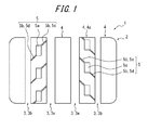
FIG. 1 is a partially developed plan view of a tread pattern of the pneumatic tire according to one embodiment; -
FIG. 2 schematically shows a Helmholtz-type resonator with one narrowed neck (a), and with two narrowed necks (b); -
FIG. 3 is a perspective view illustrating an embodiment of forming the resonator in the pneumatic tire ofFIG. 1 ; -
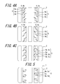
FIG. 4 is a developed plan view similar toFIG. 1 of modified examples of each of the narrowed neck and the air chamber in the pneumatic tire ofFIG. 1 ; -
FIG. 5 is a developed plan view similar toFIG. 1 of a modified example of the extending direction from the air chamber of the narrowed neck in the pneumatic tire ofFIG. 1 . - The following describes one embodiment of the disclosure in detail with reference to the drawings.
-
FIG. 1 is a partially developed plan view of a tread pattern ofpneumatic tire 1 according to one embodiment of the disclosure. Since the internal reinforcing structure and the like of the tire are similar to those of a general radial tire, they are not illustrated. - In a
pneumatic tire 1 according to one embodiment of the disclosure, at least two circumferential grooves 3 continuously extending substantially in the tread circumferential direction are provided on atread surface 2. InFIG. 1 , four circumferential grooves 3 are provided on atread surface 2.FIG. 1 shows a form where the circumferential grooves 3 extend in a linear manner along the tread circumferential direction. However, as long as the circumferential grooves 3 extend continuously in the tread circumferential direction, any form of extending for example, a zigzag form, wave-like form or the like may be adopted. - Further, on the
tread surface 2, as shown inFIG. 1 , three rows of rib-shaped land parts 4 are defined in the inner side in the tire width direction by circumferential grooves 3 adjacent to each other, and two rows of rib-shaped land parts 4 are defined in the outer side in the tire width direction (shoulder parts) by the circumferential groove 3 and the ground contact end in the outer side in the tire width direction of thetread surface 2. Further, two of the three rows of rib-shaped land parts 4 in the inner side in the tire width direction are defined by two circumferential grooves 3a and 3b which have different sectional areas. In the circumferential grooves 3 disposed on thetread surface 2 shown inFIG. 1 , from the viewpoint of ensuring drainage performance of thepneumatic tire 1, the sectional area of the circumferential groove 3a located in the inner side in the tire width direction is larger than the sectional area of the circumferential groove 3b in the outer side in the tire width direction. However, it is also possible to make the sectional area of the circumferential groove 3b in the outer side in the tire width direction larger than the sectional area of the circumferential groove 3a located in the inner side in the tire width direction. Further, as shown inFIG. 1 , the large/small relation between the respective sectional areas of the two circumferential grooves 3a and 3b is created by varying the groove width of the circumferential grooves. However, the relation can be created by varying the depth, or both the width and the depth of each circumferential groove. - In the rib-shaped
land part 4a defined between two circumferential grooves 3a and 3b having different sectional areas, as shown inFIG. 1 , aresonator 5 having anair chamber 5a opened to the land part surface in a position separated away from the circumferential groove 3, a narrowedneck 5b communicating theair chamber 5a with one of the two circumferential grooves 3a and 3b, and anarrowed neck 5b communicating theair chamber 5a with the other circumferential groove, is disposed. Further, as shown inFIG. 1 , one narrowedneck 5b is opened to one circumferential groove 3 and the other circumferential groove 3 respectively. However, it is also possible to make two or morenarrowed necks 5b opened to one circumferential groove 3 and the other circumferential groove 3, respectively or only in one side. - Meanwhile, with a resonator comprising one or more narrowed necks opened to one circumferential groove, and one or more narrowed necks having the same sectional area as said narrowed neck(s), opened to the other circumferential groove, there were cases where the air column resonance sound was hardly reduced.
- Therefore, in the
pneumatic tire 1 of the disclosure, theresonator 5 is formed so that the sectional area S1 of the narrowed neck (first narrowed neck) 5c which opens to the circumferential groove 3a with a relatively large sectional area is larger than the sectional area S2 of the narrowed neck (second narrow neck) 5d which opens to the circumferential groove 3b with a relatively small sectional area. - With this
pneumatic tire 1, among the dimensions and shapes of the narrowedneck 5b andair chamber 5a constituting theresonator 5, particularly, the sectional areas S1 and S2 of each narrowedneck 5b opened to the circumferential grooves 3 are varied. Therefore, resonance from theresonator 5 generated respectively via the narrowedneck 5c of theresonator 5, opened to the circumferential groove 3a with a relatively large sectional area and the narrowedneck 5d of theresonator 5, opened to the circumferential groove 3b with a relatively small sectional area would not cancel each other, and accordingly theresonator 5 is allowed to sufficiently function. Further, since the sectional area of the narrowedneck 5b opened to the side where the sound pressure of air column resonance sound generated in the circumferential groove 3 becomes relatively large i.e. the circumferential groove 3a with a relatively large sectional area, theresonator 5 is allowed to resonate more effectively, and therefore the noise reduction performance exhibited by theresonator 5 can be improved. Further, by improving the noise reduction performance of theresonator 5, for example, the number ofresonators 5 to dispose in thetread surface 2 can be reduced to improve rigidity inland parts 4 while maintaining an equivalent noise reduction performance, and therefore the steering stability of thetire 1 can be enhanced. Further, flexibility in the terms of designs of the tread pattern can be enhanced. For example, various types ofresonators 5 having different resonance frequency can be disposed in thetread surface 2. - In the
pneumatic tire 1 described herein, as long as the sectional areas of the two circumferential grooves 3a and 3b defining the rib-shapedland part 4a with theresonator 5 disposed thereon are different from each other, the sectional areas of circumferential grooves 3 other than the two circumferential grooves 3a and 3b having different sectional areas may be made the same as each other or different from each other. Further, intread surface 2, other resonators comprising an air chamber and a narrowed neck may be disposed in the rib-shapedland parts 4 in the center side in the tire width direction and the outer side in the tire width direction shown inFIG. 1 . - Further, as shown in
FIG. 1 , the large/small relation between respective sectional areas S1, S2 of the first narrowedneck 5c and the second narrowedneck 5d is created by varying the width of each narrowed neck. However, the relation can be created by varying the depth, or both the width and the depth of each narrowed neck. - Here, the sectional area S1 of the first narrowed
neck 5c and the sectional area S2 of the second narrowedneck 5d preferably satisfy the relation of S1/S2 ≥ 1.2. By satisfying this relation, the phenomenon where the resonance from theresonator 5 generated through the first and second narrowednecks resonator 5 is allowed to further sufficiently function. Further, it is possible to allow theresonator 5 to more effectively function against the air column resonance sound with a relatively large sound pressure, generated in the circumferential groove 3a having a relatively large sectional area. - Although the upper limit of the ratio of the
sectional area S 1 of the first narrowedneck 5c to the sectional area S2 of the second narrowedneck 5d is not limited, if the sectional area S1 of the first narrowedneck 5c is excessively larger than the sectional area S2 of the second narrowedneck 5d, it tends to be difficult to form theresonator 5 so that it has a desired resonance frequency. Therefore, it is more preferable that the sectional area S1 of the first narrowedneck 5c and the sectional area S2 of the second narrowedneck 5d satisfy the relation of 3 ≥ S1/S2 ≥ 1.2. Further, as mentioned above, from the viewpoint of easily forming theresonator 5 so that it has a desired resonance frequency while allowing theresonator 5 to more effectively function, it is further preferable that the sectional area S1 of the first narrowedneck 5c and the sectional area S2 of the second narrowedneck 5d satisfy the relation of 2 ≥ S1/S2 ≥ 1.2. - Regarding the narrowed
neck 5b and theair chamber 5a of theresonator 5, as long as they open to the road surface in the ground contact surface under the ground contact conditions mentioned above, and a desired resonance frequency is generated, the width, depth, form of extending, or the like are not particularly limited. Regarding the narrowedneck 5b, for a tire assembled with an applicable rim and in a state where prescribed air pressure is applied and no load is applied, for example, the width opened to the land part surface is preferably in the range of 0.5 mm to 2.0 mm, and more preferably in the range of 0.7 mm to 2.0 mm. From the viewpoint of forming theresonator 5 so that it has a desired resonance frequency and allowing it to sufficiently function, the depth from thetread surface 2 of the narrowed neck is preferably 1/3 to 1/2 of the depth from thetread surface 2 of the circumferential groove 3 to which the narrowedneck 5b opens. The cross sectional shape along the direction perpendicular to the extending direction of the narrowedneck 5b, as shown inFIG. 3 , can be formed as for example, squares such as rectangles (FIG. 3(a) ), or a so-called flask shape having an enlarged part in the bottom part of the narrowedneck 5b (FIG. 3(b) ). The form of extending of the narrowedneck 5b, as shown inFIG. 4(a) , can be a straight shape, a bent shape, a curved shape or a combination thereof. Although not shown in the drawings, the sidewalls of the narrowedneck 5b may be provided with a plurality of projections projected from the sidewalls, to prevent the narrowedneck 5b from unexpectedly closing. - Regarding the dimension, shape and the like of the above narrowed
neck 5b, each of the plurality of narrowednecks 5b of oneresonator 5 may be made so that they are the same as each other or different from each other. Further, the dimension, shape and the like of the narrowednecks 5b of a plurality ofresonators 5 in one row of rib-shapedland parts 4a or in different rib-shapedland parts 4a, may be made so that they are the same as each other or different from each other. - Further, regarding the
air chamber 5a of theresonator 5, as shown inFIG. 4(a) , the opening shape of theair chamber 5a to the surface of theland part 4a can be made a shape of a polygonal outline, or a shape of a curved outline such as a round shape, oval shape and the like. Further, the shape of the bottom part of theair chamber 5a can be made a flat shape, a curved shape and the like. Further, the opening shapes and the like of the eachair chamber 5a of the plurality ofresonators 5 in one row of rib-shapedland parts 4a or in different rib-shapedland parts 4a can be made the same as or different from each other. - In
FIG. 4(b) , the dimensions of theair chambers 5a are varied to vary the resonance frequencies of theresonators 5. However, as mentioned above, by varying the dimensions, shapes and the like of the narrowednecks 5b and/or theair chambers 5a of theresonators 5, a plurality ofresonators 5 each having different resonance frequencies can be disposed in the rib-shapedland parts 4a of thetread surface 2. - To form a
resonator 5 disposed in thetread surface 2 so that it has a desired resonance frequency and to allow it to sufficiently function, and for example, to open everynarrowed neck 5b of theresonator 5 to the road surface in the ground contact surface under the ground contact conditions mentioned above, the total number of first narrowednecks 5c and second narrowednecks 5d of aresonator 5 is preferably two to four. - The
resonator 5 shown inFIG. 4(c) has two first narrowednecks 5c and one second narrowedneck 5d, and more first narrowednecks 5c are disposed compared to second narrowednecks 5d. However, it is also possible to dispose more second narrowednecks 5d than first narrowednecks 5c. - For the
pneumatic tire 1 described herein, the extending direction of each of the first narrowedneck 5c and the second narrowedneck 5d to theair chamber 5a is not particularly limited. However, from the viewpoint of reducing the pitch noise generated when the edges opened to the land part surface, of the narrowedneck 5b and theair chamber 5a collides with the road surface when thetire 1 rolls, it is preferable that each of the first narrowedneck 5c and the second narrowedneck 5d do not extend toward the inner side in tread circumferential direction with respect to theair chamber 5a as shown inFIG. 5 , but that they extend toward the outer side in tread circumferential direction with respect to theair chamber 5a as shown inFIG. 1 . In other words, it is preferable to extend narrowednecks necks air chamber 5a in the width direction of the rib-shapedland parts 4a. Further, from such viewpoint, as shown inFIG. 1 , narrowednecks air chamber 5a to the outer side in tread circumferential direction and opened to circumferential grooves 3a, 3b. - In
FIG. 1 , regardingresonators 5 disposed in thetread surface 2,resonators 5 in one rib-shapedland part 4a are positioned so as to be deviated to resonators in the other rib-shapedland part 4a, in the tread circumferential direction. However, they may be disposed in the same position in the tread circumferential direction. - In the rib-shaped
land parts 4a defined between two circumferential grooves 3a and 3b having different sectional areas, it is possible to dispose, in addition to aresonator 5 having a first narrowedneck 5c and a second narrowedneck 5d, a resonator with only one narrowed neck and/or a resonator wherein the respective sectional areas of the first narrowed neck and the second narrowed neck are the same. - Embodiments of the disclosure have been explained with reference to the drawings. However, the pneumatic tire disclosed herein is not intended to be limited to the above examples and may be modified as appropriate.
- Although the disclosure will be described below in further detail with reference to examples, the disclosure is not intended to be limited in any way to the following examples.
- Sample tires of examples according to an embodiment of the disclosure and sample tires of comparative example were prepared, and the following
experiments 1 to 3 were conducted. - In
experiment 1, using pneumatic tires provided, in the tread surface, with four circumferential grooves extending in the tread circumferential direction with the sectional area of the two circumferential grooves in the inner side in tire width direction being larger than that of the two circumferential grooves in the outer side in the tire width direction, and having a Helmholtz-type resonator in the rib-shaped land part defined between two circumferential grooves having different sectional areas, the following sample tires with the respective sectional areas of one first narrowed neck and one second narrowed neck of the resonator varied were prepared. With these tires, the reduction effect of air column resonance sound generated in the circumferential groove was confirmed by a noise test. - The tire of example 1 is a pneumatic tire for an automobile with a tire size of 195/45R15 having a tread pattern shown in
FIG. 1 , wherein two circumferential grooves in the inner side in the tire width direction have a sectional area of 80 mm2 (width 10 mm,depth 8 mm), two circumferential grooves in the outer side in the tire width direction have a sectional area of 64 mm2 (width 8 mm,depth 8 mm). Further, regarding the resonator, the sectional area of the first narrowed neck is 3.3 mm2 (width 0.83 mm,depth 4 mm), the length of the first narrowed neck is 10 mm, the sectional area of the second narrowed neck is 3 mm2 (width 0.75 mm,depth 4 mm), the length of the second narrowed neck is 10 mm, the volume of the air chamber is 1560 mm3, the resonance frequency thereof is 1020 Hz, and fifty-two of them were disposed in one row of rib-shaped land parts. - Other than that the sectional areas of the first narrowed neck and the second narrowed neck were changed to specifications shown in Table 1 and that each dimension of the narrowed neck was adjusted so that the resonance frequency is the same as that of the tire of example 1, the tires of examples 2 to 6 were prepared in the same way as the tires of example 1.
- Further, other than that the sectional areas of the first narrowed neck and the second narrowed neck were changed to specifications shown in Table 1 and that each dimension of the narrowed neck was adjusted, the tires of comparative examples 1 and 2 were prepared in the same way as example 1.
- When performing the noise test for air column resonance sound, the above tires were attached to a rim with a size of 7.5J-15, applied with air pressure of 180 kPa inside, and then mounted onto a vehicle. The vehicle was driven at a constant speed of 80 km/h, and then the engine was stopped to allow the vehicle to coast. At a position 7.5 m sideward from the center of the vehicle and a height from the ground of 1.2 m, lateral noise was measured in accordance with conditions specified by JASO C606, and overall values of the center frequency band of 800 Hz - 1000 Hz - 1250 Hz in the 1/3 octave band were obtained. Smaller overall values indicate larger noise reducing effect of the resonator disposed in the tread surface of the pneumatic tire. The results are shown in Table 1.
- The resonators disposed on these sample tires satisfy the above formulas (1) and (2), and the speed of sound c was 343.7 m/s.
[Table 1] Noise Test (dB) S1/S2 Sectional Area S1 of First Narrowed Neck (mm2) Sectional Area S2 of Second Narrowed Neck (mm2) Volume of Air Chamber (mm3) Resonance Frequency (Hz) Sectional Area of Circumferential Groove (mm2) Comparative Example 1 65.2 0.9 2.7 3 1560 1000 80/64 Comparative Example 2 65.5 1 3 3 1560 1010 80/64 Example 1 65 1.1 3.3 3 1560 1020 80/64 Example 2 64.5 1.2 3.6 3 1560 1000 80/64 Example 3 64.6 1.4 4.2 3 1560 990 80/64 Example 4 64.7 2.9 4.35 1.5 1560 1000 80/64 Example 5 64.7 3 4.5 1.5 1560 1010 80/64 Example 6 64.9 3.1 4.65 1.5 1560 1020 80/64 - As a result of this test, it was revealed that, for the tires of examples 1 to 6, since the sectional area of the first narrowed neck was made larger than the sectional area of the second narrowed neck, air column resonance sound is reduced compared to the tire of comparative examples 1 and 2. Further, it was revealed that, for the tires of examples 2 to 6, the
sectional area S 1 of the first narrowed neck and the sectional area S2 of the second narrowed neck were set to satisfy a relation of S1/S2 ≥ 1.2, and therefore air column resonance sound is further reduced compared to the tire of example 1. - In
experiment 2, using the tire of example 2, and without changing the resonance frequency of the resonators and the relation between the total sectional area of the first narrowed necks and the total sectional area of the second narrowed necks, the numbers of the first narrowed necks and the second narrowed necks were changed to prepare the following sample tires, and the reduction effect of air column resonance sound generated in the circumferential groove was confirmed by a noise test. - Other than the changes described below, the following tires were prepared in the same way as the tire of example 2. Regarding the tire of example 7, the number of first narrowed necks was changed to two. Regarding the tire of example 8, the number of second narrowed necks was changed to two. Regarding the tire of example 9, the numbers of first narrowed necks and second narrowed necks were each changed to two.
- Further, the noise test was performed in the same way as the above described method. The results are shown in Table 2.
[Table 2] Noise Test (dB) S1/S2 First Narrowed Neck Second Narrowed Neck Number of Narrowed Necks Sectional Area S1' (mm2) Number of Narrowed Necks Sectional Area S2' (mm2) Comparative Example 2 65.5 1 1 3 1 3 Example 2 64.5 1.2 1 3.6 1 3 Example 7 64.5 1.2 2 1.8 1 3 Example 8 64.5 1.2 1 3.6 2 1.5 Example 9 64.5 1.2 2 1.8 2 1.5 *Sectional areas S1' and S2' indicate the respective sectional areas of one narrowed neck. Here, S1 = S1' x number of narrowed necks, S2 = S2' x number of narrowed necks. - As a result of this test, it was revealed that, with the tires of examples 2, and 7 to 9, even if the number of narrowed necks is changed, the air column resonance sound is reduced compared to the tire of comparative example 2.
- In experiment 3, using the tire of example 2, the respective extending directions from the air chamber of the first narrowed neck and the second narrowed neck were directed toward the inner side in the tread circumferential direction with respect to the air chamber to prepare a sample tire of example 10 having a tread pattern shown in
FIG. 5 , and the reduction effect of air column resonance sound generated in the circumferential groove and pitch noise was confirmed by a noise test. - In the noise test for pitch noise, measurement was conducted in the same way as the noise test for air column resonance, and as the pitch noise frequency varies depending on the speed of the vehicle, circumferential length of the tire, number of resonators, and the like, the overall values of a center frequency value of 630 Hz, in the 1/3 octave band were determined as the pitch noise and the values thereof were obtained for each sample tire. The smaller overall values indicate that more pitch noise is reduced. The results are shown in Table 3.
[Table 3] Noise Test (dB) S1/S2 Extending Direction from Air Chamber of Narrowed Neck Example 2 64.5 1.2 Outer Side in Circumferential Direction Example 10 65.6 1.2 Inner Side in Circumferential Direction - As a result of this test, with the tire of example 2, since the respective extending directions from the air chamber of the first narrowed neck and the second narrowed neck were directed toward the outer side in the tread circumferential direction with respect to the air chamber, the pitch noise is reduced compared to the tire of example 10.
- It is possible to provide a pneumatic tire with improved noise reduction performance exhibited by a resonator.
-
- 1 Pneumatic tire
- 2 Tread surface
- 3 Circumferential groove
- 3a Circumferential groove (with relatively large sectional area)
- 3b Circumferential groove (with relatively small sectional area)
- 4 Rib-shaped land part
- 4a Rib-shaped land part (defined between two circumferential grooves having different sectional areas)
- 5 Resonator
- 5a Air chamber
- 5b Narrowed neck
- 5c Narrowed neck (opened to circumferential groove with relatively large sectional area)
- 5d Narrowed neck (opened to circumferential groove with relatively small sectional area)
- 6 (Modeled) resonator
- 7, 7a, 7b Narrowed neck (of modeled resonator)
- 8 Air chamber (of modeled resonator)
- S1 Sectional area of narrowed neck (opened to circumferential groove with relatively large sectional area)
- S2 Sectional area of narrowed neck (opened to circumferential groove with relatively small sectional area)
Claims (2)
- A pneumatic tire provided, in a tread surface, with at least two circumferential grooves continuously extending in a tread circumferential direction, and a resonator disposed in a land part defined between two circumferential grooves having different sectional areas of the at least two circumferential grooves, the resonator having an air chamber opened to a land part surface in a position separated away from the circumferential groove, one or more narrowed necks communicating the air chamber with one of the two circumferential grooves, and one or more narrowed necks communicating the air chamber with the other circumferential groove, wherein
a sectional area S 1 of the narrowed neck of the resonator, opened to a circumferential groove with a relatively large sectional area is larger than a sectional area S2 of the narrowed neck of the resonator, opened to a circumferential groove with a relatively small sectional area. - The pneumatic tire according to claim 1, wherein the sectional area S1 and the sectional area S2 of the narrowed necks satisfy a relation of S1/S2 ≥ 1.2.
Applications Claiming Priority (2)
| Application Number | Priority Date | Filing Date | Title |
|---|---|---|---|
| JP2013039761A JP6166913B2 (en) | 2013-02-28 | 2013-02-28 | Pneumatic tire |
| PCT/JP2014/000590 WO2014132568A1 (en) | 2013-02-28 | 2014-02-04 | Pneumatic tire |
Publications (3)
| Publication Number | Publication Date |
|---|---|
| EP2962872A1 true EP2962872A1 (en) | 2016-01-06 |
| EP2962872A4 EP2962872A4 (en) | 2016-03-02 |
| EP2962872B1 EP2962872B1 (en) | 2017-04-26 |
Family
ID=51427848
Family Applications (1)
| Application Number | Title | Priority Date | Filing Date |
|---|---|---|---|
| EP14756805.9A Active EP2962872B1 (en) | 2013-02-28 | 2014-02-04 | Pneumatic tire |
Country Status (5)
| Country | Link |
|---|---|
| US (1) | US10131187B2 (en) |
| EP (1) | EP2962872B1 (en) |
| JP (1) | JP6166913B2 (en) |
| CN (1) | CN105026178B (en) |
| WO (1) | WO2014132568A1 (en) |
Cited By (3)
| Publication number | Priority date | Publication date | Assignee | Title |
|---|---|---|---|---|
| WO2020128237A1 (en) * | 2018-12-19 | 2020-06-25 | Compagnie Generale Des Etablissements Michelin | Tread comprising interrupted grooves |
| FR3090479A1 (en) * | 2018-12-19 | 2020-06-26 | Compagnie Generale Des Etablissements Michelin | Tread with interrupted grooves. |
| EP3858642A1 (en) * | 2019-11-12 | 2021-08-04 | Hankook Tire & Technology Co., Ltd | Tire with resonators for noise reduction |
Families Citing this family (7)
| Publication number | Priority date | Publication date | Assignee | Title |
|---|---|---|---|---|
| JP5920533B2 (en) * | 2014-05-01 | 2016-05-18 | 横浜ゴム株式会社 | Pneumatic tire |
| JP6851858B2 (en) | 2017-03-02 | 2021-03-31 | 株式会社ブリヂストン | tire |
| JP6851859B2 (en) | 2017-03-02 | 2021-03-31 | 株式会社ブリヂストン | tire |
| JP6887908B2 (en) | 2017-07-27 | 2021-06-16 | 株式会社ブリヂストン | tire |
| JP7144206B2 (en) * | 2018-06-18 | 2022-09-29 | 株式会社ブリヂストン | tire |
| JP7091232B2 (en) * | 2018-11-27 | 2022-06-27 | 株式会社ブリヂストン | tire |
| KR102857788B1 (en) * | 2023-07-18 | 2025-09-09 | 한국타이어앤테크놀로지 주식회사 | Pneumatic tire for noise reduction |
Family Cites Families (12)
| Publication number | Priority date | Publication date | Assignee | Title |
|---|---|---|---|---|
| JPH05338411A (en) | 1992-06-10 | 1993-12-21 | Hino Motors Ltd | Low noise rib tire |
| WO2007114430A1 (en) | 2006-03-31 | 2007-10-11 | Bridgestone Corporation | Pneumatic tire |
| JP5013731B2 (en) * | 2006-03-31 | 2012-08-29 | 株式会社ブリヂストン | Pneumatic tire |
| US8297323B2 (en) * | 2007-02-19 | 2012-10-30 | Bridgestone Corporation | Pneumatic tire |
| JP5518473B2 (en) * | 2007-05-29 | 2014-06-11 | 株式会社ブリヂストン | Pneumatic tire |
| JP4156018B1 (en) * | 2007-12-12 | 2008-09-24 | 横浜ゴム株式会社 | Pneumatic tire |
| JP5350874B2 (en) * | 2009-04-30 | 2013-11-27 | 株式会社ブリヂストン | Pneumatic tire |
| JP5255520B2 (en) | 2009-05-28 | 2013-08-07 | 株式会社ブリヂストン | Pneumatic tire |
| JP5271813B2 (en) * | 2009-06-03 | 2013-08-21 | 株式会社ブリヂストン | tire |
| JP5291739B2 (en) * | 2011-03-02 | 2013-09-18 | 住友ゴム工業株式会社 | Pneumatic tire |
| US9751365B2 (en) * | 2011-09-13 | 2017-09-05 | The Goodyear Tire & Rubber Company | High mileage truck tire tread |
| JP6076137B2 (en) * | 2013-02-28 | 2017-02-08 | 株式会社ブリヂストン | Pneumatic tire |
-
2013
- 2013-02-28 JP JP2013039761A patent/JP6166913B2/en not_active Expired - Fee Related
-
2014
- 2014-02-04 WO PCT/JP2014/000590 patent/WO2014132568A1/en not_active Ceased
- 2014-02-04 CN CN201480011344.0A patent/CN105026178B/en active Active
- 2014-02-04 US US14/766,630 patent/US10131187B2/en active Active
- 2014-02-04 EP EP14756805.9A patent/EP2962872B1/en active Active
Cited By (6)
| Publication number | Priority date | Publication date | Assignee | Title |
|---|---|---|---|---|
| WO2020128237A1 (en) * | 2018-12-19 | 2020-06-25 | Compagnie Generale Des Etablissements Michelin | Tread comprising interrupted grooves |
| FR3090479A1 (en) * | 2018-12-19 | 2020-06-26 | Compagnie Generale Des Etablissements Michelin | Tread with interrupted grooves. |
| CN113195259A (en) * | 2018-12-19 | 2021-07-30 | 米其林集团总公司 | Tread comprising discontinuous grooves |
| US11951773B2 (en) | 2018-12-19 | 2024-04-09 | Compagnie Generale Des Etablissements Michelin | Tread comprising interrupted grooves |
| EP3858642A1 (en) * | 2019-11-12 | 2021-08-04 | Hankook Tire & Technology Co., Ltd | Tire with resonators for noise reduction |
| AU2020267251B2 (en) * | 2019-11-12 | 2022-11-17 | Hankook Tire & Technology Co., Ltd | Tires with resonators for noise reduction |
Also Published As
| Publication number | Publication date |
|---|---|
| EP2962872B1 (en) | 2017-04-26 |
| JP2014166827A (en) | 2014-09-11 |
| US10131187B2 (en) | 2018-11-20 |
| EP2962872A4 (en) | 2016-03-02 |
| US20150375570A1 (en) | 2015-12-31 |
| CN105026178A (en) | 2015-11-04 |
| WO2014132568A1 (en) | 2014-09-04 |
| CN105026178B (en) | 2017-10-13 |
| JP6166913B2 (en) | 2017-07-19 |
Similar Documents
| Publication | Publication Date | Title |
|---|---|---|
| EP2962872B1 (en) | Pneumatic tire | |
| US10744824B2 (en) | Pneumatic tire | |
| EP3081392B1 (en) | Tire | |
| EP3572243B1 (en) | Tire | |
| EP0671287A1 (en) | Pneumatic tyre | |
| US9649885B2 (en) | Pneumatic tire | |
| JP7091232B2 (en) | tire | |
| US11535062B2 (en) | Tyre | |
| EP3725556B1 (en) | Pneumatic tire | |
| EP2962873B1 (en) | Pneumatic tire | |
| JP5740025B2 (en) | Pneumatic tire | |
| EP3725555B1 (en) | Pneumatic tire |
Legal Events
| Date | Code | Title | Description |
|---|---|---|---|
| PUAI | Public reference made under article 153(3) epc to a published international application that has entered the european phase |
Free format text: ORIGINAL CODE: 0009012 |
|
| 17P | Request for examination filed |
Effective date: 20150827 |
|
| AK | Designated contracting states |
Kind code of ref document: A1 Designated state(s): AL AT BE BG CH CY CZ DE DK EE ES FI FR GB GR HR HU IE IS IT LI LT LU LV MC MK MT NL NO PL PT RO RS SE SI SK SM TR |
|
| AX | Request for extension of the european patent |
Extension state: BA ME |
|
| A4 | Supplementary search report drawn up and despatched |
Effective date: 20160202 |
|
| RIC1 | Information provided on ipc code assigned before grant |
Ipc: B60C 11/12 20060101ALI20160127BHEP Ipc: B60C 11/03 20060101AFI20160127BHEP Ipc: B60C 19/00 20060101ALI20160127BHEP |
|
| DAX | Request for extension of the european patent (deleted) | ||
| REG | Reference to a national code |
Ref country code: DE Ref legal event code: R079 Ref document number: 602014009109 Country of ref document: DE Free format text: PREVIOUS MAIN CLASS: B60C0011000000 Ipc: B60C0011030000 |
|
| GRAP | Despatch of communication of intention to grant a patent |
Free format text: ORIGINAL CODE: EPIDOSNIGR1 |
|
| RIC1 | Information provided on ipc code assigned before grant |
Ipc: B60C 11/03 20060101AFI20161011BHEP Ipc: B60C 19/00 20060101ALN20161011BHEP |
|
| INTG | Intention to grant announced |
Effective date: 20161111 |
|
| GRAS | Grant fee paid |
Free format text: ORIGINAL CODE: EPIDOSNIGR3 |
|
| GRAA | (expected) grant |
Free format text: ORIGINAL CODE: 0009210 |
|
| AK | Designated contracting states |
Kind code of ref document: B1 Designated state(s): AL AT BE BG CH CY CZ DE DK EE ES FI FR GB GR HR HU IE IS IT LI LT LU LV MC MK MT NL NO PL PT RO RS SE SI SK SM TR |
|
| REG | Reference to a national code |
Ref country code: GB Ref legal event code: FG4D |
|
| REG | Reference to a national code |
Ref country code: CH Ref legal event code: EP |
|
| REG | Reference to a national code |
Ref country code: AT Ref legal event code: REF Ref document number: 887535 Country of ref document: AT Kind code of ref document: T Effective date: 20170515 |
|
| REG | Reference to a national code |
Ref country code: IE Ref legal event code: FG4D |
|
| REG | Reference to a national code |
Ref country code: DE Ref legal event code: R096 Ref document number: 602014009109 Country of ref document: DE |
|
| REG | Reference to a national code |
Ref country code: NL Ref legal event code: MP Effective date: 20170426 |
|
| REG | Reference to a national code |
Ref country code: LT Ref legal event code: MG4D |
|
| REG | Reference to a national code |
Ref country code: AT Ref legal event code: MK05 Ref document number: 887535 Country of ref document: AT Kind code of ref document: T Effective date: 20170426 |
|
| PG25 | Lapsed in a contracting state [announced via postgrant information from national office to epo] |
Ref country code: NL Free format text: LAPSE BECAUSE OF FAILURE TO SUBMIT A TRANSLATION OF THE DESCRIPTION OR TO PAY THE FEE WITHIN THE PRESCRIBED TIME-LIMIT Effective date: 20170426 |
|
| PG25 | Lapsed in a contracting state [announced via postgrant information from national office to epo] |
Ref country code: FI Free format text: LAPSE BECAUSE OF FAILURE TO SUBMIT A TRANSLATION OF THE DESCRIPTION OR TO PAY THE FEE WITHIN THE PRESCRIBED TIME-LIMIT Effective date: 20170426 Ref country code: ES Free format text: LAPSE BECAUSE OF FAILURE TO SUBMIT A TRANSLATION OF THE DESCRIPTION OR TO PAY THE FEE WITHIN THE PRESCRIBED TIME-LIMIT Effective date: 20170426 Ref country code: GR Free format text: LAPSE BECAUSE OF FAILURE TO SUBMIT A TRANSLATION OF THE DESCRIPTION OR TO PAY THE FEE WITHIN THE PRESCRIBED TIME-LIMIT Effective date: 20170727 Ref country code: LT Free format text: LAPSE BECAUSE OF FAILURE TO SUBMIT A TRANSLATION OF THE DESCRIPTION OR TO PAY THE FEE WITHIN THE PRESCRIBED TIME-LIMIT Effective date: 20170426 Ref country code: AT Free format text: LAPSE BECAUSE OF FAILURE TO SUBMIT A TRANSLATION OF THE DESCRIPTION OR TO PAY THE FEE WITHIN THE PRESCRIBED TIME-LIMIT Effective date: 20170426 Ref country code: HR Free format text: LAPSE BECAUSE OF FAILURE TO SUBMIT A TRANSLATION OF THE DESCRIPTION OR TO PAY THE FEE WITHIN THE PRESCRIBED TIME-LIMIT Effective date: 20170426 Ref country code: NO Free format text: LAPSE BECAUSE OF FAILURE TO SUBMIT A TRANSLATION OF THE DESCRIPTION OR TO PAY THE FEE WITHIN THE PRESCRIBED TIME-LIMIT Effective date: 20170726 |
|
| PG25 | Lapsed in a contracting state [announced via postgrant information from national office to epo] |
Ref country code: BG Free format text: LAPSE BECAUSE OF FAILURE TO SUBMIT A TRANSLATION OF THE DESCRIPTION OR TO PAY THE FEE WITHIN THE PRESCRIBED TIME-LIMIT Effective date: 20170726 Ref country code: IS Free format text: LAPSE BECAUSE OF FAILURE TO SUBMIT A TRANSLATION OF THE DESCRIPTION OR TO PAY THE FEE WITHIN THE PRESCRIBED TIME-LIMIT Effective date: 20170826 Ref country code: LV Free format text: LAPSE BECAUSE OF FAILURE TO SUBMIT A TRANSLATION OF THE DESCRIPTION OR TO PAY THE FEE WITHIN THE PRESCRIBED TIME-LIMIT Effective date: 20170426 Ref country code: RS Free format text: LAPSE BECAUSE OF FAILURE TO SUBMIT A TRANSLATION OF THE DESCRIPTION OR TO PAY THE FEE WITHIN THE PRESCRIBED TIME-LIMIT Effective date: 20170426 Ref country code: PL Free format text: LAPSE BECAUSE OF FAILURE TO SUBMIT A TRANSLATION OF THE DESCRIPTION OR TO PAY THE FEE WITHIN THE PRESCRIBED TIME-LIMIT Effective date: 20170426 Ref country code: SE Free format text: LAPSE BECAUSE OF FAILURE TO SUBMIT A TRANSLATION OF THE DESCRIPTION OR TO PAY THE FEE WITHIN THE PRESCRIBED TIME-LIMIT Effective date: 20170426 |
|
| REG | Reference to a national code |
Ref country code: DE Ref legal event code: R097 Ref document number: 602014009109 Country of ref document: DE |
|
| PG25 | Lapsed in a contracting state [announced via postgrant information from national office to epo] |
Ref country code: RO Free format text: LAPSE BECAUSE OF FAILURE TO SUBMIT A TRANSLATION OF THE DESCRIPTION OR TO PAY THE FEE WITHIN THE PRESCRIBED TIME-LIMIT Effective date: 20170426 Ref country code: DK Free format text: LAPSE BECAUSE OF FAILURE TO SUBMIT A TRANSLATION OF THE DESCRIPTION OR TO PAY THE FEE WITHIN THE PRESCRIBED TIME-LIMIT Effective date: 20170426 Ref country code: CZ Free format text: LAPSE BECAUSE OF FAILURE TO SUBMIT A TRANSLATION OF THE DESCRIPTION OR TO PAY THE FEE WITHIN THE PRESCRIBED TIME-LIMIT Effective date: 20170426 Ref country code: SK Free format text: LAPSE BECAUSE OF FAILURE TO SUBMIT A TRANSLATION OF THE DESCRIPTION OR TO PAY THE FEE WITHIN THE PRESCRIBED TIME-LIMIT Effective date: 20170426 Ref country code: EE Free format text: LAPSE BECAUSE OF FAILURE TO SUBMIT A TRANSLATION OF THE DESCRIPTION OR TO PAY THE FEE WITHIN THE PRESCRIBED TIME-LIMIT Effective date: 20170426 |
|
| REG | Reference to a national code |
Ref country code: FR Ref legal event code: PLFP Year of fee payment: 5 |
|
| PG25 | Lapsed in a contracting state [announced via postgrant information from national office to epo] |
Ref country code: SM Free format text: LAPSE BECAUSE OF FAILURE TO SUBMIT A TRANSLATION OF THE DESCRIPTION OR TO PAY THE FEE WITHIN THE PRESCRIBED TIME-LIMIT Effective date: 20170426 Ref country code: IT Free format text: LAPSE BECAUSE OF FAILURE TO SUBMIT A TRANSLATION OF THE DESCRIPTION OR TO PAY THE FEE WITHIN THE PRESCRIBED TIME-LIMIT Effective date: 20170426 |
|
| PLBE | No opposition filed within time limit |
Free format text: ORIGINAL CODE: 0009261 |
|
| STAA | Information on the status of an ep patent application or granted ep patent |
Free format text: STATUS: NO OPPOSITION FILED WITHIN TIME LIMIT |
|
| 26N | No opposition filed |
Effective date: 20180129 |
|
| PG25 | Lapsed in a contracting state [announced via postgrant information from national office to epo] |
Ref country code: SI Free format text: LAPSE BECAUSE OF FAILURE TO SUBMIT A TRANSLATION OF THE DESCRIPTION OR TO PAY THE FEE WITHIN THE PRESCRIBED TIME-LIMIT Effective date: 20170426 |
|
| REG | Reference to a national code |
Ref country code: CH Ref legal event code: PL |
|
| PG25 | Lapsed in a contracting state [announced via postgrant information from national office to epo] |
Ref country code: MC Free format text: LAPSE BECAUSE OF FAILURE TO SUBMIT A TRANSLATION OF THE DESCRIPTION OR TO PAY THE FEE WITHIN THE PRESCRIBED TIME-LIMIT Effective date: 20170426 |
|
| GBPC | Gb: european patent ceased through non-payment of renewal fee |
Effective date: 20180204 |
|
| REG | Reference to a national code |
Ref country code: IE Ref legal event code: MM4A |
|
| REG | Reference to a national code |
Ref country code: BE Ref legal event code: MM Effective date: 20180228 |
|
| PG25 | Lapsed in a contracting state [announced via postgrant information from national office to epo] |
Ref country code: CH Free format text: LAPSE BECAUSE OF NON-PAYMENT OF DUE FEES Effective date: 20180228 Ref country code: LU Free format text: LAPSE BECAUSE OF NON-PAYMENT OF DUE FEES Effective date: 20180204 Ref country code: LI Free format text: LAPSE BECAUSE OF NON-PAYMENT OF DUE FEES Effective date: 20180228 |
|
| PG25 | Lapsed in a contracting state [announced via postgrant information from national office to epo] |
Ref country code: IE Free format text: LAPSE BECAUSE OF NON-PAYMENT OF DUE FEES Effective date: 20180204 |
|
| PG25 | Lapsed in a contracting state [announced via postgrant information from national office to epo] |
Ref country code: GB Free format text: LAPSE BECAUSE OF NON-PAYMENT OF DUE FEES Effective date: 20180204 Ref country code: BE Free format text: LAPSE BECAUSE OF NON-PAYMENT OF DUE FEES Effective date: 20180228 |
|
| PG25 | Lapsed in a contracting state [announced via postgrant information from national office to epo] |
Ref country code: MT Free format text: LAPSE BECAUSE OF NON-PAYMENT OF DUE FEES Effective date: 20180204 |
|
| PG25 | Lapsed in a contracting state [announced via postgrant information from national office to epo] |
Ref country code: TR Free format text: LAPSE BECAUSE OF FAILURE TO SUBMIT A TRANSLATION OF THE DESCRIPTION OR TO PAY THE FEE WITHIN THE PRESCRIBED TIME-LIMIT Effective date: 20170426 |
|
| PG25 | Lapsed in a contracting state [announced via postgrant information from national office to epo] |
Ref country code: PT Free format text: LAPSE BECAUSE OF FAILURE TO SUBMIT A TRANSLATION OF THE DESCRIPTION OR TO PAY THE FEE WITHIN THE PRESCRIBED TIME-LIMIT Effective date: 20170426 |
|
| PG25 | Lapsed in a contracting state [announced via postgrant information from national office to epo] |
Ref country code: MK Free format text: LAPSE BECAUSE OF NON-PAYMENT OF DUE FEES Effective date: 20170426 Ref country code: CY Free format text: LAPSE BECAUSE OF FAILURE TO SUBMIT A TRANSLATION OF THE DESCRIPTION OR TO PAY THE FEE WITHIN THE PRESCRIBED TIME-LIMIT Effective date: 20170426 Ref country code: HU Free format text: LAPSE BECAUSE OF FAILURE TO SUBMIT A TRANSLATION OF THE DESCRIPTION OR TO PAY THE FEE WITHIN THE PRESCRIBED TIME-LIMIT; INVALID AB INITIO Effective date: 20140204 |
|
| PG25 | Lapsed in a contracting state [announced via postgrant information from national office to epo] |
Ref country code: AL Free format text: LAPSE BECAUSE OF FAILURE TO SUBMIT A TRANSLATION OF THE DESCRIPTION OR TO PAY THE FEE WITHIN THE PRESCRIBED TIME-LIMIT Effective date: 20170426 |
|
| P01 | Opt-out of the competence of the unified patent court (upc) registered |
Effective date: 20230531 |
|
| PGFP | Annual fee paid to national office [announced via postgrant information from national office to epo] |
Ref country code: FR Payment date: 20240221 Year of fee payment: 11 |
|
| PG25 | Lapsed in a contracting state [announced via postgrant information from national office to epo] |
Ref country code: FR Free format text: LAPSE BECAUSE OF NON-PAYMENT OF DUE FEES Effective date: 20250228 |
|
| PGFP | Annual fee paid to national office [announced via postgrant information from national office to epo] |
Ref country code: DE Payment date: 20260218 Year of fee payment: 13 |