EP2962848B1 - Tintenhärtungsvorrichtung - Google Patents
Tintenhärtungsvorrichtung Download PDFInfo
- Publication number
- EP2962848B1 EP2962848B1 EP15170727.0A EP15170727A EP2962848B1 EP 2962848 B1 EP2962848 B1 EP 2962848B1 EP 15170727 A EP15170727 A EP 15170727A EP 2962848 B1 EP2962848 B1 EP 2962848B1
- Authority
- EP
- European Patent Office
- Prior art keywords
- lamp
- fitting
- terminal
- curing apparatus
- ink curing
- Prior art date
- Legal status (The legal status is an assumption and is not a legal conclusion. Google has not performed a legal analysis and makes no representation as to the accuracy of the status listed.)
- Active
Links
Images


Classifications
-
- B—PERFORMING OPERATIONS; TRANSPORTING
- B41—PRINTING; LINING MACHINES; TYPEWRITERS; STAMPS
- B41J—TYPEWRITERS; SELECTIVE PRINTING MECHANISMS, i.e. MECHANISMS PRINTING OTHERWISE THAN FROM A FORME; CORRECTION OF TYPOGRAPHICAL ERRORS
- B41J11/00—Devices or arrangements of selective printing mechanisms, e.g. ink-jet printers or thermal printers, for supporting or handling copy material in sheet or web form
- B41J11/0015—Devices or arrangements of selective printing mechanisms, e.g. ink-jet printers or thermal printers, for supporting or handling copy material in sheet or web form for treating before, during or after printing or for uniform coating or laminating the copy material before or after printing
- B41J11/002—Curing or drying the ink on the copy materials, e.g. by heating or irradiating
- B41J11/0021—Curing or drying the ink on the copy materials, e.g. by heating or irradiating using irradiation
- B41J11/00214—Curing or drying the ink on the copy materials, e.g. by heating or irradiating using irradiation using UV radiation
-
- B—PERFORMING OPERATIONS; TRANSPORTING
- B05—SPRAYING OR ATOMISING IN GENERAL; APPLYING FLUENT MATERIALS TO SURFACES, IN GENERAL
- B05D—PROCESSES FOR APPLYING FLUENT MATERIALS TO SURFACES, IN GENERAL
- B05D3/00—Pretreatment of surfaces to which liquids or other fluent materials are to be applied; After-treatment of applied coatings, e.g. intermediate treating of an applied coating preparatory to subsequent applications of liquids or other fluent materials
- B05D3/06—Pretreatment of surfaces to which liquids or other fluent materials are to be applied; After-treatment of applied coatings, e.g. intermediate treating of an applied coating preparatory to subsequent applications of liquids or other fluent materials by exposure to radiation
- B05D3/061—Pretreatment of surfaces to which liquids or other fluent materials are to be applied; After-treatment of applied coatings, e.g. intermediate treating of an applied coating preparatory to subsequent applications of liquids or other fluent materials by exposure to radiation using U.V.
- B05D3/065—After-treatment
- B05D3/067—Curing or cross-linking the coating
-
- B—PERFORMING OPERATIONS; TRANSPORTING
- B41—PRINTING; LINING MACHINES; TYPEWRITERS; STAMPS
- B41F—PRINTING MACHINES OR PRESSES
- B41F23/00—Devices for treating the surfaces of sheets, webs, or other articles in connection with printing
- B41F23/04—Devices for treating the surfaces of sheets, webs, or other articles in connection with printing by heat drying, by cooling, by applying powders
- B41F23/0403—Drying webs
- B41F23/0406—Drying webs by radiation
- B41F23/0409—Ultraviolet dryers
-
- B—PERFORMING OPERATIONS; TRANSPORTING
- B41—PRINTING; LINING MACHINES; TYPEWRITERS; STAMPS
- B41F—PRINTING MACHINES OR PRESSES
- B41F23/00—Devices for treating the surfaces of sheets, webs, or other articles in connection with printing
- B41F23/04—Devices for treating the surfaces of sheets, webs, or other articles in connection with printing by heat drying, by cooling, by applying powders
- B41F23/044—Drying sheets, e.g. between two printing stations
- B41F23/045—Drying sheets, e.g. between two printing stations by radiation
- B41F23/0453—Drying sheets, e.g. between two printing stations by radiation by ultraviolet dryers
Definitions
- the present invention relates to a UV lamp. More specifically, the invention relates to a UV lamp for use with ink curing apparatus used commonly in the printing industry.
- Lamps used in ink curing apparatus generally comprise a glass tube with an electrode extending into each end of the lamp tube. It is common for the terminal assembly at each end of the tube to be pinch sealed and received within a small ceramic block into which the free end of each electrode also extends. A wire extends out of the ceramic block for connection to the electricity supply used to power the lamp.
- Existing lamp terminal arrangements are connected to the ink curing apparatus using a threaded screw clamped with a nut.
- the applicant's earlier UK patent application no. GB1004255.4 discloses a simplified lamp terminal arrangement having a male/female connection means at each end of the lamp.
- UV lamps for use in ink curing machines are run at high intensities and consequently have a limited life span such that lamps have to be frequently cleaned and changed.
- the length of the lamp and the possibility of marking or breaking the glass tube mean that it is important for care to be taken when inserting a lamp into the apparatus.
- Existing lamps require a first end of the lamp to be inserted before a second end of the lamp is inserted to enable both ends of the lamp to be secured to the ink curing apparatus. Manoeuvring both ends of the lamp in this way often makes maintenance and repair difficult for a single person to complete; that is, safely inserting the lamp into the housing often requires two people.
- the present invention seeks to alleviate the aforementioned disadvantages with known UV lamps by providing an improved ink curing apparatus that allows a UV lamp to be conveniently and safely changed, whilst reducing the time and cost of maintenance of the UV curing apparatus.
- an ink curing apparatus comprising:a lamp housing with a lamp fitting for a lamp terminal of a UV lamp at each opposing end, wherein the lamp terminal comprises all components at the end of the lamp, including an electrical connector;wherein at least one of the lamp fittings is non-conducting and has a non-conducting lamp terminal seat,characterised by having a concave profile for receiving a substantially spherical lamp terminal end piece;whereby, in use during the fitting or removal of a lamp, the oreach lamp fitting allows a lamp terminal end piece to roll over the lamp terminal seat and move in multiple degrees of freedom, whilst the movement is restricted such that the lamp terminal is retained substantially in position at the lamp fitting.
- the present invention allows for a lamp to be fitted and replaced by a single user, because the first end of the lamp is held in position whilst connection is made at the second end of the lamp.
- the first end of the lamp is not rigidly held to allow the second end of the lamp to be manoeuvred into position. Maintenance of the improved UV curing apparatus is safer, quicker and more convenient, whilst reducing maintenance costs and safeguarding against accidental damage to the lamp.
- the "lamp terminal” is understood to comprise all components at the end of the lamp, including the electrical connector. It is also understood that “restricted movement” refers to limited movement over a receiving surface, where the lamp terminal will ultimately be fixed.
- the end pieces of the lamp housing have a profile, which is preferably substantially spherical.
- the lamp together with the concave configuration of the lamp fitting this allows the lamp to be easily manoeuvred through multiple degrees of freedom; for example the permitted movement at the or each lamp end is akin to that of a ball and socket joint.
- the present invention allows for installation and removal of a lamp safely and quickly by a single user because there is no axial constraint.
- the present invention mitigates the risk of the lamp being damaged when fitting or removing the lamp from the housing.
- the or each lamp fitting is made of a ceramic or similar insulating material.
- An insulating material prevents the risk of electrical tracking or short circuits between the lamp fitting and the aluminium lamp housing.
- the or each lamp fitting is a two-part device comprising a lamp terminal seat and a closure means.
- the electrical tracking distance between the lamp terminal and the conducting lamp housing is increased to prevent electrical tracking and short circuiting.
- the lamp terminal seat is curved.
- the lamp terminal seat is U-shaped.
- a curved, U-shaped lamp terminal seat allows for a complementary-shaped lamp terminal to smoothly roll over the seat, and move in all degrees of freedom, around the lamp fitting.
- the present invention provides a UV lamp configured to be received in an ink curing apparatus as described above, the lamp having a lamp terminal with at least one non-conducting end piece, wherein the profile of the non-conducting end piece is substantially spherical for rolling over the lamp terminal seat and moving in multiple degrees of freedom.
- the or each curved end piece is made of ceramic or similar insulating material.
- a curved or substantially spherical lamp end piece rolls easily over a complementary curved lamp terminal seat to allow a user to easily manoeuvre the lamp into position.
- the shape of the lamp terminal allows the lamp to be easily manoeuvred through multiple degrees of freedom; for example the permitted movement at the or each lamp end is akin to that of a ball and socket joint.
- the present invention allows for installation and removal of a lamp safely and quickly by a single user because there is no axial constraint and mitigates the risk of the lamp being damaged when fitting or removing the lamp from the housing.
- the ink curing apparatus comprises a lamp housing 1, which is an interchangeable "cassette” for use in ultra violet (UV) print curing.
- Each end of the lamp housing 1 of the present embodiment comprises an aluminium end plate 5.
- a second endplate at the opposing end of the lamp housing 1 is not shown in Figure 1 .
- the cassette 3 comprises a lamp fitting 7, 9 at each opposing end.
- the lamp fitting comprises a curved ceramic body 7 fixed to the cassette 3 and a removable ceramic closure member 9 between which an opening 11 is defined.
- the cassette 3 is provided with a connection means (not shown) for connecting and disconnecting a UV lamp 13 to and from the power connected to the housing 1.
- connection means is a plug/socket arrangement allowing a lamp 13 to be connected into cassette 3 using a "push-fit" connection.
- the lamp 13 has a rod-shaped, hollow main body made, for example, of quartz.
- the main body has located therein chemical compounds to provide ultra violet (UV) radiation when an electrical source is applied to the lamp 13.
- UV ultra violet
- the cassette 3 optionally comprises a pivotable lamp door 15, which is hinged about a knurled screw 17.
- the configuration of the lamp door 15 ensures that, when both ends of the lamp 13 are connected to their respective push fit connections, and the lamp door 15 is closed, the lamp 13 is retained so that it cannot fall out in any orientation.
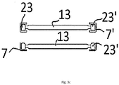
- a UV lamp 13 comprises a lamp terminal assembly 21 at each of its ends.
- the assembly 21 comprises a curved ceramic block 23, having a substantially circular cross-section.
- the ceramic block 23 is a lamp terminal end piece, which has an outer surface, which is substantially spherical.
- the sphere is truncated to provide two opposing flat surfaces 23a, 23b. That is, the ceramic block 23 of the lamp terminal end piece is a sphere having a segment cap cut off by planar surfaces 23a, 23b.
- the ceramic block 23 of the lamp terminal end piece has a cylindrical hollow passing through it into which the lamp 13 is fixed.
- An electrode (not shown) passes into the glass tube 19 of the lamp 13 and into the curved ceramic block 23.
- the ceramic block 23 at each end of the lamp 13 provides for ease of insertion and removal of the lamp 13 into and from the end plate 5 and curved ceramic body 7.
- the diameter at the widest point of the curved ceramic block 23 is about 1mm less than the greatest width of the opening 11 provided by the curved ceramic body 7.
- the curved ceramic block 23 of a first end of the lamp 13 is placed on the curved receiving face 7a of the ceramic body 7, which acts as a terminal seat.
- the ceramic closure member 9 of the cassette 3 is closed i.e. placed over the ceramic body 7 to restrict the movement of the first end of the lamp 13.
- the ceramic block 23 of the lamp terminal 21 rolls over the curved face 7a of the ceramic body 7, so that the lamp 13 is moveable about multiple axes in all degrees of freedom, whilst still being held, i.e. substantially retained, within the lamp end ceramic fitting 7, 9; i.e. so that movement is restricted.
- a first end of the lamp 13 is placed on the curved face 7a of the ceramic body 7 with the ceramic closure member 9 placed over the ceramic body 7 at the lamp end so that movement of the lamp 13 is restricted.
- the ceramic block 23' of the lamp terminal is moved over the ceramic block 7 so that the lamp 13 can be fitted whilst the lamp 13 is out of line, thus reducing the possibility of snapping the lamp end 11.
- the configuration of the lamp fitting 7 allows for movement of the lamp 13 in all degrees of freedom, but restricts movement of the first end lamp terminal 21 out of the fitting, which comprises the ceramic body 7 and the closure member 9.
- the fitting prevents the first end of the lamp 13 disengaging with the fitting 7.
- the curved ceramic face 7a of the lamp fitting allows the curved ceramic block 23 to rotate about multiple axis; i.e. it can be manoeuvred through multiple degrees of freedom. This allows the ceramic block 23' at the other, i.e. second, end of the lamp 13 to be positioned into the respective ceramic fitting, which comprises a ceramic body 7' and closure member (not shown), without any risk of damage to the first end of the lamp 13.
- the distance between the lamp's electrical connection i.e. between the lamp terminal assembly 21 and the aluminium end plate 5 of the cassette 3 is sufficient to ensure that the electrical connection is insulated by the ceramic components 7, 9, 23 described above. This significantly decreases any risk of electrical tracking or short circuiting between the lamp's electrical connection and the end plate 5.
- the connection to the cassette 3 and the lamp 13 is disconnected.
- the lamp door 15 at each end of the lamp cassette 3 is opened; the ceramic closure member 9 is removed and a first end of the lamp 13 is removed from the curved ceramic body 7.
- the second end of the lamp 13 is moveable in all degrees of freedom, whilst still be held within the ceramic fitting 7, 9.
- the curved ceramic body of the lamp fitting is allowed to rotate about multiple axis and so has multiple degrees of freedom.
- the second lamp terminal 21' is also removed from the respective ceramic fitting and so from the cassette 3.
Landscapes
- Health & Medical Sciences (AREA)
- General Health & Medical Sciences (AREA)
- Toxicology (AREA)
- Engineering & Computer Science (AREA)
- Mechanical Engineering (AREA)
- Physics & Mathematics (AREA)
- Plasma & Fusion (AREA)
- Supply, Installation And Extraction Of Printed Sheets Or Plates (AREA)
- Physical Or Chemical Processes And Apparatus (AREA)
- Ink Jet (AREA)
- Fastening Of Light Sources Or Lamp Holders (AREA)
Claims (7)
- Tintenhärtungsvorrichtung, umfassend:ein Lampengehäuse (1) mit einer Lampenfassung (7, 9, 7') für einen Lampenanschluss (21) von einer UV-Lampe (13) an jedem entgegengesetzten Ende, wobei der Lampenanschluss alle Komponenten an dem Ende der Lampe umfasst, einschließlich eines elektrischen Verbinders;wobei mindestens eine der Lampenfassungen (7, 9, 7') nicht-leitend ist und eine nicht-leitende Lampenanschlussauflage (7, 7') aufweist, gekennzeichnet durch Aufweisen eines konkaven Profils zum Aufnehmen eines im Wesentlichen kugelförmigen Lampenanschlussendstücks (23);wobei bei Verwendung während des Fassens oder Entfernens einer Lampe (13), die oder jede Lampenfassung (7, 9, 7') einem Lampenanschlussendstück (23, 23') erlaubt, über die Lampenanschlussauflage zu rollen und sich in mehrfachen Freiheitsgraden zu bewegen, während die Bewegung beschränkt ist, sodass der Lampenanschluss im Wesentlichen in Position an der Lampenfassung (7, 9, 7') verbleibt.
- Tintenhärtungsvorrichtung nach Anspruch 1, wobei die oder jede Lampenfassung (7, 9, 7') aus einer Keramik hergestellt ist.
- Tintenhärtungsvorrichtung nach Anspruch 1 oder Anspruch 2, wobei die oder jede Lampenfassung (7, 9, 7') eine zweiteilige Vorrichtung ist, umfassend eine Lampenanschlussauflage (7, 7') und ein Verschlussmittel (9).
- Tintenhärtungsvorrichtung nach Anspruch 3, wobei die Lampenanschlussauflage (7, 7') gekrümmt ist.
- Tintenhärtungsvorrichtung nach Anspruch 4, wobei die Lampenanschlussauflage (7, 7') U-förmig ist.
- UV-Lampe (13), ausgelegt, um in eine Tintenhärtungsvorrichtung nach einem vorstehenden Anspruch aufgenommen zu werden, wobei die Lampe (13) einen Lampenanschluss (21) mit mindestens einem nicht-leitenden Endstück (23, 23') aufweist, wobei das Profil des nicht-leitenden Endstücks zum Rollen über die Lampenanschlussauflage und Bewegen in mehreren Freiheitsgraden im Wesentlichen kugelförmig ist.
- UV-Lampe (13) für eine Tintenhärtungsvorrichtung nach Anspruch 6, wobei das oder jedes nicht-leitende Endstück (23, 23') aus Keramik hergestellt ist.
Priority Applications (1)
| Application Number | Priority Date | Filing Date | Title |
|---|---|---|---|
| PL15170727T PL2962848T3 (pl) | 2014-07-01 | 2015-06-04 | Urządzenie do utwardzania farby |
Applications Claiming Priority (1)
| Application Number | Priority Date | Filing Date | Title |
|---|---|---|---|
| GBGB1411699.0A GB201411699D0 (en) | 2014-07-01 | 2014-07-01 | Ink curing apparatus |
Publications (2)
| Publication Number | Publication Date |
|---|---|
| EP2962848A1 EP2962848A1 (de) | 2016-01-06 |
| EP2962848B1 true EP2962848B1 (de) | 2017-09-13 |
Family
ID=51410438
Family Applications (1)
| Application Number | Title | Priority Date | Filing Date |
|---|---|---|---|
| EP15170727.0A Active EP2962848B1 (de) | 2014-07-01 | 2015-06-04 | Tintenhärtungsvorrichtung |
Country Status (6)
| Country | Link |
|---|---|
| US (1) | US9592531B2 (de) |
| EP (1) | EP2962848B1 (de) |
| DK (1) | DK2962848T3 (de) |
| ES (1) | ES2645206T3 (de) |
| GB (1) | GB201411699D0 (de) |
| PL (1) | PL2962848T3 (de) |
Families Citing this family (2)
| Publication number | Priority date | Publication date | Assignee | Title |
|---|---|---|---|---|
| CN106142829B (zh) * | 2016-08-31 | 2018-08-10 | 黑金刚(福建)自动化科技股份公司 | 一种改进的鞋面印刷装置 |
| CN109798464B (zh) * | 2019-02-01 | 2024-01-23 | 广州速普软件科技有限公司 | 一种led灯与汞灯的互换结构 |
Family Cites Families (10)
| Publication number | Priority date | Publication date | Assignee | Title |
|---|---|---|---|---|
| US3788560A (en) * | 1972-10-16 | 1974-01-29 | Gte Sylvania Inc | Lighting fixture |
| US3906217A (en) | 1974-03-14 | 1975-09-16 | Ppg Industries Inc | Lamp mounting bracket |
| GB2111767B (en) * | 1981-12-14 | 1985-01-30 | Ian Arthur Atkins | Strip light fitting |
| DE19955979A1 (de) | 1999-11-20 | 2001-05-23 | Ist Metz Gmbh | Anschlußanordnung für eine stabförmige zweiendige Entladungslampe |
| US6905230B2 (en) * | 2003-08-18 | 2005-06-14 | Nordson Corporation | UV lamp retainer system |
| WO2008073338A2 (en) * | 2006-12-11 | 2008-06-19 | Air Motion Systems, Inc. | Uv module |
| GB0722253D0 (en) | 2007-11-13 | 2007-12-27 | Gew Ec Ltd | Uv lamp |
| GB2478717A (en) * | 2010-03-15 | 2011-09-21 | Gew | Lamp housing for ink curing apparatus |
| US8926129B2 (en) * | 2010-04-08 | 2015-01-06 | Tito Socarras | LED lighting system |
| GB2495355B (en) * | 2012-07-02 | 2013-08-28 | Gew Ec Ltd | Ink curing apparatus |
-
2014
- 2014-07-01 GB GBGB1411699.0A patent/GB201411699D0/en not_active Ceased
-
2015
- 2015-06-04 DK DK15170727.0T patent/DK2962848T3/da active
- 2015-06-04 PL PL15170727T patent/PL2962848T3/pl unknown
- 2015-06-04 ES ES15170727.0T patent/ES2645206T3/es active Active
- 2015-06-04 EP EP15170727.0A patent/EP2962848B1/de active Active
- 2015-07-01 US US14/789,431 patent/US9592531B2/en active Active
Also Published As
| Publication number | Publication date |
|---|---|
| ES2645206T3 (es) | 2017-12-04 |
| US20160001321A1 (en) | 2016-01-07 |
| GB201411699D0 (en) | 2014-08-13 |
| US9592531B2 (en) | 2017-03-14 |
| PL2962848T3 (pl) | 2018-03-30 |
| EP2962848A1 (de) | 2016-01-06 |
| DK2962848T3 (da) | 2017-11-20 |
Similar Documents
| Publication | Publication Date | Title |
|---|---|---|
| TWI569530B (zh) | 電插塞連接器 | |
| EP2962848B1 (de) | Tintenhärtungsvorrichtung | |
| EP2894651A1 (de) | Batterieanordnung und elektronische Zigarette damit | |
| US7544080B2 (en) | Electrical plug connector coupling | |
| JP2008130556A (ja) | 導電体用の差込みコネクタ | |
| ES2190055T3 (es) | Dispositivo para sujetar el cable en tomas de corriente electrica o enchufes. | |
| WO2009122055A3 (fr) | Element femelle de connecteur electrique et connecteur electrique comprenant un tel element femelle | |
| US11316326B2 (en) | Thermal cartridge device | |
| CN106370971A (zh) | 一种漏电检测装置 | |
| CN110176735B (zh) | 一种硅橡胶绝缘罩插拔扣锁扣器 | |
| ITTO20030086U1 (it) | Gruppo porta-contatti per una presa-spina di connessione elettrica. | |
| JP2009071916A (ja) | 電線接続用保持具 | |
| US9050831B2 (en) | Ink curing apparatus with lamp housing and movable locking member | |
| DE50300838D1 (de) | Werkzeugwechsel- und/oder Kupplungssystem | |
| EP2139073B1 (de) | Elektrische Verbindungsbrücke und Anschlussblock | |
| JP2015177692A (ja) | 間接活線工事用アダプタ | |
| EP0592581A1 (de) | Steckerkontakt. | |
| CN104373429A (zh) | 夹持装置 | |
| ATE533204T1 (de) | Stecker für einen elektrischen leiter | |
| US7262364B2 (en) | Cable coupler clamp assembly | |
| GB2478717A (en) | Lamp housing for ink curing apparatus | |
| US8383968B2 (en) | Lever switch for safe breaking of a circuit of an exercise apparatus | |
| CN216621570U (zh) | 一种高压开关柜触头压力测量仪 | |
| CN204216274U (zh) | 一种新型安全排插 | |
| CN108539486A (zh) | 便于固定使用的医用插板 |
Legal Events
| Date | Code | Title | Description |
|---|---|---|---|
| PUAI | Public reference made under article 153(3) epc to a published international application that has entered the european phase |
Free format text: ORIGINAL CODE: 0009012 |
|
| AK | Designated contracting states |
Kind code of ref document: A1 Designated state(s): AL AT BE BG CH CY CZ DE DK EE ES FI FR GB GR HR HU IE IS IT LI LT LU LV MC MK MT NL NO PL PT RO RS SE SI SK SM TR |
|
| AX | Request for extension of the european patent |
Extension state: BA ME |
|
| 17P | Request for examination filed |
Effective date: 20160506 |
|
| RBV | Designated contracting states (corrected) |
Designated state(s): AL AT BE BG CH CY CZ DE DK EE ES FI FR GB GR HR HU IE IS IT LI LT LU LV MC MK MT NL NO PL PT RO RS SE SI SK SM TR |
|
| GRAP | Despatch of communication of intention to grant a patent |
Free format text: ORIGINAL CODE: EPIDOSNIGR1 |
|
| INTG | Intention to grant announced |
Effective date: 20170421 |
|
| GRAS | Grant fee paid |
Free format text: ORIGINAL CODE: EPIDOSNIGR3 |
|
| GRAA | (expected) grant |
Free format text: ORIGINAL CODE: 0009210 |
|
| AK | Designated contracting states |
Kind code of ref document: B1 Designated state(s): AL AT BE BG CH CY CZ DE DK EE ES FI FR GB GR HR HU IE IS IT LI LT LU LV MC MK MT NL NO PL PT RO RS SE SI SK SM TR |
|
| REG | Reference to a national code |
Ref country code: GB Ref legal event code: FG4D |
|
| REG | Reference to a national code |
Ref country code: CH Ref legal event code: EP |
|
| REG | Reference to a national code |
Ref country code: IE Ref legal event code: FG4D |
|
| REG | Reference to a national code |
Ref country code: AT Ref legal event code: REF Ref document number: 927739 Country of ref document: AT Kind code of ref document: T Effective date: 20171015 |
|
| REG | Reference to a national code |
Ref country code: DE Ref legal event code: R096 Ref document number: 602015004601 Country of ref document: DE |
|
| REG | Reference to a national code |
Ref country code: DK Ref legal event code: T3 Effective date: 20171113 |
|
| REG | Reference to a national code |
Ref country code: ES Ref legal event code: FG2A Ref document number: 2645206 Country of ref document: ES Kind code of ref document: T3 Effective date: 20171204 |
|
| REG | Reference to a national code |
Ref country code: NL Ref legal event code: MP Effective date: 20170913 |
|
| REG | Reference to a national code |
Ref country code: LT Ref legal event code: MG4D |
|
| PG25 | Lapsed in a contracting state [announced via postgrant information from national office to epo] |
Ref country code: LT Free format text: LAPSE BECAUSE OF FAILURE TO SUBMIT A TRANSLATION OF THE DESCRIPTION OR TO PAY THE FEE WITHIN THE PRESCRIBED TIME-LIMIT Effective date: 20170913 Ref country code: HR Free format text: LAPSE BECAUSE OF FAILURE TO SUBMIT A TRANSLATION OF THE DESCRIPTION OR TO PAY THE FEE WITHIN THE PRESCRIBED TIME-LIMIT Effective date: 20170913 Ref country code: SE Free format text: LAPSE BECAUSE OF FAILURE TO SUBMIT A TRANSLATION OF THE DESCRIPTION OR TO PAY THE FEE WITHIN THE PRESCRIBED TIME-LIMIT Effective date: 20170913 Ref country code: FI Free format text: LAPSE BECAUSE OF FAILURE TO SUBMIT A TRANSLATION OF THE DESCRIPTION OR TO PAY THE FEE WITHIN THE PRESCRIBED TIME-LIMIT Effective date: 20170913 Ref country code: NO Free format text: LAPSE BECAUSE OF FAILURE TO SUBMIT A TRANSLATION OF THE DESCRIPTION OR TO PAY THE FEE WITHIN THE PRESCRIBED TIME-LIMIT Effective date: 20171213 |
|
| PG25 | Lapsed in a contracting state [announced via postgrant information from national office to epo] |
Ref country code: GR Free format text: LAPSE BECAUSE OF FAILURE TO SUBMIT A TRANSLATION OF THE DESCRIPTION OR TO PAY THE FEE WITHIN THE PRESCRIBED TIME-LIMIT Effective date: 20171214 Ref country code: BG Free format text: LAPSE BECAUSE OF FAILURE TO SUBMIT A TRANSLATION OF THE DESCRIPTION OR TO PAY THE FEE WITHIN THE PRESCRIBED TIME-LIMIT Effective date: 20171213 Ref country code: LV Free format text: LAPSE BECAUSE OF FAILURE TO SUBMIT A TRANSLATION OF THE DESCRIPTION OR TO PAY THE FEE WITHIN THE PRESCRIBED TIME-LIMIT Effective date: 20170913 Ref country code: RS Free format text: LAPSE BECAUSE OF FAILURE TO SUBMIT A TRANSLATION OF THE DESCRIPTION OR TO PAY THE FEE WITHIN THE PRESCRIBED TIME-LIMIT Effective date: 20170913 |
|
| PG25 | Lapsed in a contracting state [announced via postgrant information from national office to epo] |
Ref country code: NL Free format text: LAPSE BECAUSE OF FAILURE TO SUBMIT A TRANSLATION OF THE DESCRIPTION OR TO PAY THE FEE WITHIN THE PRESCRIBED TIME-LIMIT Effective date: 20170913 |
|
| PG25 | Lapsed in a contracting state [announced via postgrant information from national office to epo] |
Ref country code: RO Free format text: LAPSE BECAUSE OF FAILURE TO SUBMIT A TRANSLATION OF THE DESCRIPTION OR TO PAY THE FEE WITHIN THE PRESCRIBED TIME-LIMIT Effective date: 20170913 Ref country code: CZ Free format text: LAPSE BECAUSE OF FAILURE TO SUBMIT A TRANSLATION OF THE DESCRIPTION OR TO PAY THE FEE WITHIN THE PRESCRIBED TIME-LIMIT Effective date: 20170913 |
|
| PG25 | Lapsed in a contracting state [announced via postgrant information from national office to epo] |
Ref country code: EE Free format text: LAPSE BECAUSE OF FAILURE TO SUBMIT A TRANSLATION OF THE DESCRIPTION OR TO PAY THE FEE WITHIN THE PRESCRIBED TIME-LIMIT Effective date: 20170913 Ref country code: SM Free format text: LAPSE BECAUSE OF FAILURE TO SUBMIT A TRANSLATION OF THE DESCRIPTION OR TO PAY THE FEE WITHIN THE PRESCRIBED TIME-LIMIT Effective date: 20170913 Ref country code: SK Free format text: LAPSE BECAUSE OF FAILURE TO SUBMIT A TRANSLATION OF THE DESCRIPTION OR TO PAY THE FEE WITHIN THE PRESCRIBED TIME-LIMIT Effective date: 20170913 Ref country code: IS Free format text: LAPSE BECAUSE OF FAILURE TO SUBMIT A TRANSLATION OF THE DESCRIPTION OR TO PAY THE FEE WITHIN THE PRESCRIBED TIME-LIMIT Effective date: 20180113 |
|
| REG | Reference to a national code |
Ref country code: DE Ref legal event code: R097 Ref document number: 602015004601 Country of ref document: DE |
|
| REG | Reference to a national code |
Ref country code: FR Ref legal event code: PLFP Year of fee payment: 4 |
|
| PLBE | No opposition filed within time limit |
Free format text: ORIGINAL CODE: 0009261 |
|
| STAA | Information on the status of an ep patent application or granted ep patent |
Free format text: STATUS: NO OPPOSITION FILED WITHIN TIME LIMIT |
|
| 26N | No opposition filed |
Effective date: 20180614 |
|
| PG25 | Lapsed in a contracting state [announced via postgrant information from national office to epo] |
Ref country code: SI Free format text: LAPSE BECAUSE OF FAILURE TO SUBMIT A TRANSLATION OF THE DESCRIPTION OR TO PAY THE FEE WITHIN THE PRESCRIBED TIME-LIMIT Effective date: 20170913 |
|
| REG | Reference to a national code |
Ref country code: IE Ref legal event code: MM4A |
|
| PG25 | Lapsed in a contracting state [announced via postgrant information from national office to epo] |
Ref country code: LU Free format text: LAPSE BECAUSE OF NON-PAYMENT OF DUE FEES Effective date: 20180604 Ref country code: MC Free format text: LAPSE BECAUSE OF FAILURE TO SUBMIT A TRANSLATION OF THE DESCRIPTION OR TO PAY THE FEE WITHIN THE PRESCRIBED TIME-LIMIT Effective date: 20170913 |
|
| PG25 | Lapsed in a contracting state [announced via postgrant information from national office to epo] |
Ref country code: IE Free format text: LAPSE BECAUSE OF NON-PAYMENT OF DUE FEES Effective date: 20180604 |
|
| PG25 | Lapsed in a contracting state [announced via postgrant information from national office to epo] |
Ref country code: MT Free format text: LAPSE BECAUSE OF NON-PAYMENT OF DUE FEES Effective date: 20180604 |
|
| PG25 | Lapsed in a contracting state [announced via postgrant information from national office to epo] |
Ref country code: TR Free format text: LAPSE BECAUSE OF FAILURE TO SUBMIT A TRANSLATION OF THE DESCRIPTION OR TO PAY THE FEE WITHIN THE PRESCRIBED TIME-LIMIT Effective date: 20170913 |
|
| PG25 | Lapsed in a contracting state [announced via postgrant information from national office to epo] |
Ref country code: PT Free format text: LAPSE BECAUSE OF FAILURE TO SUBMIT A TRANSLATION OF THE DESCRIPTION OR TO PAY THE FEE WITHIN THE PRESCRIBED TIME-LIMIT Effective date: 20170913 |
|
| PG25 | Lapsed in a contracting state [announced via postgrant information from national office to epo] |
Ref country code: MK Free format text: LAPSE BECAUSE OF NON-PAYMENT OF DUE FEES Effective date: 20170913 Ref country code: CY Free format text: LAPSE BECAUSE OF FAILURE TO SUBMIT A TRANSLATION OF THE DESCRIPTION OR TO PAY THE FEE WITHIN THE PRESCRIBED TIME-LIMIT Effective date: 20170913 Ref country code: HU Free format text: LAPSE BECAUSE OF FAILURE TO SUBMIT A TRANSLATION OF THE DESCRIPTION OR TO PAY THE FEE WITHIN THE PRESCRIBED TIME-LIMIT; INVALID AB INITIO Effective date: 20150604 |
|
| PG25 | Lapsed in a contracting state [announced via postgrant information from national office to epo] |
Ref country code: AL Free format text: LAPSE BECAUSE OF FAILURE TO SUBMIT A TRANSLATION OF THE DESCRIPTION OR TO PAY THE FEE WITHIN THE PRESCRIBED TIME-LIMIT Effective date: 20170913 |
|
| REG | Reference to a national code |
Ref country code: AT Ref legal event code: UEP Ref document number: 927739 Country of ref document: AT Kind code of ref document: T Effective date: 20170913 |
|
| P01 | Opt-out of the competence of the unified patent court (upc) registered |
Effective date: 20230523 |
|
| PGFP | Annual fee paid to national office [announced via postgrant information from national office to epo] |
Ref country code: DE Payment date: 20250618 Year of fee payment: 11 Ref country code: PL Payment date: 20250526 Year of fee payment: 11 |
|
| PGFP | Annual fee paid to national office [announced via postgrant information from national office to epo] |
Ref country code: GB Payment date: 20250501 Year of fee payment: 11 Ref country code: DK Payment date: 20250625 Year of fee payment: 11 |
|
| PGFP | Annual fee paid to national office [announced via postgrant information from national office to epo] |
Ref country code: BE Payment date: 20250618 Year of fee payment: 11 |
|
| PGFP | Annual fee paid to national office [announced via postgrant information from national office to epo] |
Ref country code: FR Payment date: 20250625 Year of fee payment: 11 |
|
| PGFP | Annual fee paid to national office [announced via postgrant information from national office to epo] |
Ref country code: AT Payment date: 20250620 Year of fee payment: 11 |
|
| PGFP | Annual fee paid to national office [announced via postgrant information from national office to epo] |
Ref country code: ES Payment date: 20250728 Year of fee payment: 11 |
|
| PGFP | Annual fee paid to national office [announced via postgrant information from national office to epo] |
Ref country code: IT Payment date: 20250619 Year of fee payment: 11 |
|
| PGFP | Annual fee paid to national office [announced via postgrant information from national office to epo] |
Ref country code: CH Payment date: 20250701 Year of fee payment: 11 |