EP2962844B1 - Visueller beschichtungsdickenanzeiger - Google Patents
Visueller beschichtungsdickenanzeiger Download PDFInfo
- Publication number
- EP2962844B1 EP2962844B1 EP15175074.2A EP15175074A EP2962844B1 EP 2962844 B1 EP2962844 B1 EP 2962844B1 EP 15175074 A EP15175074 A EP 15175074A EP 2962844 B1 EP2962844 B1 EP 2962844B1
- Authority
- EP
- European Patent Office
- Prior art keywords
- microspheres
- coating
- abradable layer
- layer
- abradable
- Prior art date
- Legal status (The legal status is an assumption and is not a legal conclusion. Google has not performed a legal analysis and makes no representation as to the accuracy of the status listed.)
- Active
Links
Images


Classifications
-
- F—MECHANICAL ENGINEERING; LIGHTING; HEATING; WEAPONS; BLASTING
- F01—MACHINES OR ENGINES IN GENERAL; ENGINE PLANTS IN GENERAL; STEAM ENGINES
- F01D—NON-POSITIVE DISPLACEMENT MACHINES OR ENGINES, e.g. STEAM TURBINES
- F01D11/00—Preventing or minimising internal leakage of working-fluid, e.g. between stages
- F01D11/08—Preventing or minimising internal leakage of working-fluid, e.g. between stages for sealing space between rotor blade tips and stator
- F01D11/12—Preventing or minimising internal leakage of working-fluid, e.g. between stages for sealing space between rotor blade tips and stator using a rubstrip, e.g. erodible. deformable or resiliently-biased part
- F01D11/122—Preventing or minimising internal leakage of working-fluid, e.g. between stages for sealing space between rotor blade tips and stator using a rubstrip, e.g. erodible. deformable or resiliently-biased part with erodable or abradable material
-
- B—PERFORMING OPERATIONS; TRANSPORTING
- B05—SPRAYING OR ATOMISING IN GENERAL; APPLYING FLUENT MATERIALS TO SURFACES, IN GENERAL
- B05D—PROCESSES FOR APPLYING FLUENT MATERIALS TO SURFACES, IN GENERAL
- B05D1/00—Processes for applying liquids or other fluent materials
- B05D1/36—Successively applying liquids or other fluent materials, e.g. without intermediate treatment
-
- B—PERFORMING OPERATIONS; TRANSPORTING
- B05—SPRAYING OR ATOMISING IN GENERAL; APPLYING FLUENT MATERIALS TO SURFACES, IN GENERAL
- B05D—PROCESSES FOR APPLYING FLUENT MATERIALS TO SURFACES, IN GENERAL
- B05D5/00—Processes for applying liquids or other fluent materials to surfaces to obtain special surface effects, finishes or structures
- B05D5/06—Processes for applying liquids or other fluent materials to surfaces to obtain special surface effects, finishes or structures to obtain multicolour or other optical effects
- B05D5/061—Special surface effect
-
- B—PERFORMING OPERATIONS; TRANSPORTING
- B05—SPRAYING OR ATOMISING IN GENERAL; APPLYING FLUENT MATERIALS TO SURFACES, IN GENERAL
- B05D—PROCESSES FOR APPLYING FLUENT MATERIALS TO SURFACES, IN GENERAL
- B05D7/00—Processes, other than flocking, specially adapted for applying liquids or other fluent materials to particular surfaces or for applying particular liquids or other fluent materials
- B05D7/14—Processes, other than flocking, specially adapted for applying liquids or other fluent materials to particular surfaces or for applying particular liquids or other fluent materials to metal, e.g. car bodies
-
- B—PERFORMING OPERATIONS; TRANSPORTING
- B32—LAYERED PRODUCTS
- B32B—LAYERED PRODUCTS, i.e. PRODUCTS BUILT-UP OF STRATA OF FLAT OR NON-FLAT, e.g. CELLULAR OR HONEYCOMB, FORM
- B32B18/00—Layered products essentially comprising ceramics, e.g. refractory products
-
- C—CHEMISTRY; METALLURGY
- C04—CEMENTS; CONCRETE; ARTIFICIAL STONE; CERAMICS; REFRACTORIES
- C04B—LIME, MAGNESIA; SLAG; CEMENTS; COMPOSITIONS THEREOF, e.g. MORTARS, CONCRETE OR LIKE BUILDING MATERIALS; ARTIFICIAL STONE; CERAMICS; REFRACTORIES; TREATMENT OF NATURAL STONE
- C04B35/00—Shaped ceramic products characterised by their composition; Ceramics compositions; Processing powders of inorganic compounds preparatory to the manufacturing of ceramic products
- C04B35/50—Shaped ceramic products characterised by their composition; Ceramics compositions; Processing powders of inorganic compounds preparatory to the manufacturing of ceramic products based on rare-earth compounds
-
- C—CHEMISTRY; METALLURGY
- C04—CEMENTS; CONCRETE; ARTIFICIAL STONE; CERAMICS; REFRACTORIES
- C04B—LIME, MAGNESIA; SLAG; CEMENTS; COMPOSITIONS THEREOF, e.g. MORTARS, CONCRETE OR LIKE BUILDING MATERIALS; ARTIFICIAL STONE; CERAMICS; REFRACTORIES; TREATMENT OF NATURAL STONE
- C04B35/00—Shaped ceramic products characterised by their composition; Ceramics compositions; Processing powders of inorganic compounds preparatory to the manufacturing of ceramic products
- C04B35/622—Forming processes; Processing powders of inorganic compounds preparatory to the manufacturing of ceramic products
- C04B35/62222—Forming processes; Processing powders of inorganic compounds preparatory to the manufacturing of ceramic products obtaining ceramic coatings
-
- C—CHEMISTRY; METALLURGY
- C04—CEMENTS; CONCRETE; ARTIFICIAL STONE; CERAMICS; REFRACTORIES
- C04B—LIME, MAGNESIA; SLAG; CEMENTS; COMPOSITIONS THEREOF, e.g. MORTARS, CONCRETE OR LIKE BUILDING MATERIALS; ARTIFICIAL STONE; CERAMICS; REFRACTORIES; TREATMENT OF NATURAL STONE
- C04B41/00—After-treatment of mortars, concrete, artificial stone or ceramics; Treatment of natural stone
- C04B41/009—After-treatment of mortars, concrete, artificial stone or ceramics; Treatment of natural stone characterised by the material treated
-
- C—CHEMISTRY; METALLURGY
- C04—CEMENTS; CONCRETE; ARTIFICIAL STONE; CERAMICS; REFRACTORIES
- C04B—LIME, MAGNESIA; SLAG; CEMENTS; COMPOSITIONS THEREOF, e.g. MORTARS, CONCRETE OR LIKE BUILDING MATERIALS; ARTIFICIAL STONE; CERAMICS; REFRACTORIES; TREATMENT OF NATURAL STONE
- C04B41/00—After-treatment of mortars, concrete, artificial stone or ceramics; Treatment of natural stone
- C04B41/45—Coating or impregnating, e.g. injection in masonry, partial coating of green or fired ceramics, organic coating compositions for adhering together two concrete elements
- C04B41/50—Coating or impregnating, e.g. injection in masonry, partial coating of green or fired ceramics, organic coating compositions for adhering together two concrete elements with inorganic materials
- C04B41/5024—Silicates
-
- C—CHEMISTRY; METALLURGY
- C04—CEMENTS; CONCRETE; ARTIFICIAL STONE; CERAMICS; REFRACTORIES
- C04B—LIME, MAGNESIA; SLAG; CEMENTS; COMPOSITIONS THEREOF, e.g. MORTARS, CONCRETE OR LIKE BUILDING MATERIALS; ARTIFICIAL STONE; CERAMICS; REFRACTORIES; TREATMENT OF NATURAL STONE
- C04B41/00—After-treatment of mortars, concrete, artificial stone or ceramics; Treatment of natural stone
- C04B41/45—Coating or impregnating, e.g. injection in masonry, partial coating of green or fired ceramics, organic coating compositions for adhering together two concrete elements
- C04B41/52—Multiple coating or impregnating multiple coating or impregnating with the same composition or with compositions only differing in the concentration of the constituents, is classified as single coating or impregnation
-
- C—CHEMISTRY; METALLURGY
- C04—CEMENTS; CONCRETE; ARTIFICIAL STONE; CERAMICS; REFRACTORIES
- C04B—LIME, MAGNESIA; SLAG; CEMENTS; COMPOSITIONS THEREOF, e.g. MORTARS, CONCRETE OR LIKE BUILDING MATERIALS; ARTIFICIAL STONE; CERAMICS; REFRACTORIES; TREATMENT OF NATURAL STONE
- C04B41/00—After-treatment of mortars, concrete, artificial stone or ceramics; Treatment of natural stone
- C04B41/80—After-treatment of mortars, concrete, artificial stone or ceramics; Treatment of natural stone of only ceramics
- C04B41/81—Coating or impregnation
- C04B41/85—Coating or impregnation with inorganic materials
- C04B41/87—Ceramics
-
- C—CHEMISTRY; METALLURGY
- C04—CEMENTS; CONCRETE; ARTIFICIAL STONE; CERAMICS; REFRACTORIES
- C04B—LIME, MAGNESIA; SLAG; CEMENTS; COMPOSITIONS THEREOF, e.g. MORTARS, CONCRETE OR LIKE BUILDING MATERIALS; ARTIFICIAL STONE; CERAMICS; REFRACTORIES; TREATMENT OF NATURAL STONE
- C04B41/00—After-treatment of mortars, concrete, artificial stone or ceramics; Treatment of natural stone
- C04B41/80—After-treatment of mortars, concrete, artificial stone or ceramics; Treatment of natural stone of only ceramics
- C04B41/81—Coating or impregnation
- C04B41/89—Coating or impregnation for obtaining at least two superposed coatings having different compositions
-
- C—CHEMISTRY; METALLURGY
- C23—COATING METALLIC MATERIAL; COATING MATERIAL WITH METALLIC MATERIAL; CHEMICAL SURFACE TREATMENT; DIFFUSION TREATMENT OF METALLIC MATERIAL; COATING BY VACUUM EVAPORATION, BY SPUTTERING, BY ION IMPLANTATION OR BY CHEMICAL VAPOUR DEPOSITION, IN GENERAL; INHIBITING CORROSION OF METALLIC MATERIAL OR INCRUSTATION IN GENERAL
- C23C—COATING METALLIC MATERIAL; COATING MATERIAL WITH METALLIC MATERIAL; SURFACE TREATMENT OF METALLIC MATERIAL BY DIFFUSION INTO THE SURFACE, BY CHEMICAL CONVERSION OR SUBSTITUTION; COATING BY VACUUM EVAPORATION, BY SPUTTERING, BY ION IMPLANTATION OR BY CHEMICAL VAPOUR DEPOSITION, IN GENERAL
- C23C14/00—Coating by vacuum evaporation, by sputtering or by ion implantation of the coating forming material
- C23C14/06—Coating by vacuum evaporation, by sputtering or by ion implantation of the coating forming material characterised by the coating material
- C23C14/14—Metallic material, boron or silicon
-
- C—CHEMISTRY; METALLURGY
- C23—COATING METALLIC MATERIAL; COATING MATERIAL WITH METALLIC MATERIAL; CHEMICAL SURFACE TREATMENT; DIFFUSION TREATMENT OF METALLIC MATERIAL; COATING BY VACUUM EVAPORATION, BY SPUTTERING, BY ION IMPLANTATION OR BY CHEMICAL VAPOUR DEPOSITION, IN GENERAL; INHIBITING CORROSION OF METALLIC MATERIAL OR INCRUSTATION IN GENERAL
- C23C—COATING METALLIC MATERIAL; COATING MATERIAL WITH METALLIC MATERIAL; SURFACE TREATMENT OF METALLIC MATERIAL BY DIFFUSION INTO THE SURFACE, BY CHEMICAL CONVERSION OR SUBSTITUTION; COATING BY VACUUM EVAPORATION, BY SPUTTERING, BY ION IMPLANTATION OR BY CHEMICAL VAPOUR DEPOSITION, IN GENERAL
- C23C16/00—Chemical coating by decomposition of gaseous compounds, without leaving reaction products of surface material in the coating, i.e. chemical vapour deposition [CVD] processes
- C23C16/22—Chemical coating by decomposition of gaseous compounds, without leaving reaction products of surface material in the coating, i.e. chemical vapour deposition [CVD] processes characterised by the deposition of inorganic material, other than metallic material
- C23C16/24—Deposition of silicon only
-
- C—CHEMISTRY; METALLURGY
- C23—COATING METALLIC MATERIAL; COATING MATERIAL WITH METALLIC MATERIAL; CHEMICAL SURFACE TREATMENT; DIFFUSION TREATMENT OF METALLIC MATERIAL; COATING BY VACUUM EVAPORATION, BY SPUTTERING, BY ION IMPLANTATION OR BY CHEMICAL VAPOUR DEPOSITION, IN GENERAL; INHIBITING CORROSION OF METALLIC MATERIAL OR INCRUSTATION IN GENERAL
- C23C—COATING METALLIC MATERIAL; COATING MATERIAL WITH METALLIC MATERIAL; SURFACE TREATMENT OF METALLIC MATERIAL BY DIFFUSION INTO THE SURFACE, BY CHEMICAL CONVERSION OR SUBSTITUTION; COATING BY VACUUM EVAPORATION, BY SPUTTERING, BY ION IMPLANTATION OR BY CHEMICAL VAPOUR DEPOSITION, IN GENERAL
- C23C28/00—Coating for obtaining at least two superposed coatings either by methods not provided for in a single one of groups C23C2/00 - C23C26/00 or by combinations of methods provided for in subclasses C23C and C25C or C25D
- C23C28/04—Coating for obtaining at least two superposed coatings either by methods not provided for in a single one of groups C23C2/00 - C23C26/00 or by combinations of methods provided for in subclasses C23C and C25C or C25D only coatings of inorganic non-metallic material
- C23C28/044—Coating for obtaining at least two superposed coatings either by methods not provided for in a single one of groups C23C2/00 - C23C26/00 or by combinations of methods provided for in subclasses C23C and C25C or C25D only coatings of inorganic non-metallic material coatings specially adapted for cutting tools or wear applications
-
- C—CHEMISTRY; METALLURGY
- C23—COATING METALLIC MATERIAL; COATING MATERIAL WITH METALLIC MATERIAL; CHEMICAL SURFACE TREATMENT; DIFFUSION TREATMENT OF METALLIC MATERIAL; COATING BY VACUUM EVAPORATION, BY SPUTTERING, BY ION IMPLANTATION OR BY CHEMICAL VAPOUR DEPOSITION, IN GENERAL; INHIBITING CORROSION OF METALLIC MATERIAL OR INCRUSTATION IN GENERAL
- C23C—COATING METALLIC MATERIAL; COATING MATERIAL WITH METALLIC MATERIAL; SURFACE TREATMENT OF METALLIC MATERIAL BY DIFFUSION INTO THE SURFACE, BY CHEMICAL CONVERSION OR SUBSTITUTION; COATING BY VACUUM EVAPORATION, BY SPUTTERING, BY ION IMPLANTATION OR BY CHEMICAL VAPOUR DEPOSITION, IN GENERAL
- C23C28/00—Coating for obtaining at least two superposed coatings either by methods not provided for in a single one of groups C23C2/00 - C23C26/00 or by combinations of methods provided for in subclasses C23C and C25C or C25D
- C23C28/30—Coatings combining at least one metallic layer and at least one inorganic non-metallic layer
- C23C28/32—Coatings combining at least one metallic layer and at least one inorganic non-metallic layer including at least one pure metallic layer
- C23C28/321—Coatings combining at least one metallic layer and at least one inorganic non-metallic layer including at least one pure metallic layer with at least one metal alloy layer
-
- C—CHEMISTRY; METALLURGY
- C23—COATING METALLIC MATERIAL; COATING MATERIAL WITH METALLIC MATERIAL; CHEMICAL SURFACE TREATMENT; DIFFUSION TREATMENT OF METALLIC MATERIAL; COATING BY VACUUM EVAPORATION, BY SPUTTERING, BY ION IMPLANTATION OR BY CHEMICAL VAPOUR DEPOSITION, IN GENERAL; INHIBITING CORROSION OF METALLIC MATERIAL OR INCRUSTATION IN GENERAL
- C23C—COATING METALLIC MATERIAL; COATING MATERIAL WITH METALLIC MATERIAL; SURFACE TREATMENT OF METALLIC MATERIAL BY DIFFUSION INTO THE SURFACE, BY CHEMICAL CONVERSION OR SUBSTITUTION; COATING BY VACUUM EVAPORATION, BY SPUTTERING, BY ION IMPLANTATION OR BY CHEMICAL VAPOUR DEPOSITION, IN GENERAL
- C23C28/00—Coating for obtaining at least two superposed coatings either by methods not provided for in a single one of groups C23C2/00 - C23C26/00 or by combinations of methods provided for in subclasses C23C and C25C or C25D
- C23C28/30—Coatings combining at least one metallic layer and at least one inorganic non-metallic layer
- C23C28/34—Coatings combining at least one metallic layer and at least one inorganic non-metallic layer including at least one inorganic non-metallic material layer, e.g. metal carbide, nitride, boride, silicide layer and their mixtures, enamels, phosphates and sulphates
- C23C28/345—Coatings combining at least one metallic layer and at least one inorganic non-metallic layer including at least one inorganic non-metallic material layer, e.g. metal carbide, nitride, boride, silicide layer and their mixtures, enamels, phosphates and sulphates with at least one oxide layer
-
- C—CHEMISTRY; METALLURGY
- C23—COATING METALLIC MATERIAL; COATING MATERIAL WITH METALLIC MATERIAL; CHEMICAL SURFACE TREATMENT; DIFFUSION TREATMENT OF METALLIC MATERIAL; COATING BY VACUUM EVAPORATION, BY SPUTTERING, BY ION IMPLANTATION OR BY CHEMICAL VAPOUR DEPOSITION, IN GENERAL; INHIBITING CORROSION OF METALLIC MATERIAL OR INCRUSTATION IN GENERAL
- C23C—COATING METALLIC MATERIAL; COATING MATERIAL WITH METALLIC MATERIAL; SURFACE TREATMENT OF METALLIC MATERIAL BY DIFFUSION INTO THE SURFACE, BY CHEMICAL CONVERSION OR SUBSTITUTION; COATING BY VACUUM EVAPORATION, BY SPUTTERING, BY ION IMPLANTATION OR BY CHEMICAL VAPOUR DEPOSITION, IN GENERAL
- C23C4/00—Coating by spraying the coating material in the molten state, e.g. by flame, plasma or electric discharge
- C23C4/04—Coating by spraying the coating material in the molten state, e.g. by flame, plasma or electric discharge characterised by the coating material
- C23C4/06—Metallic material
- C23C4/067—Metallic material containing free particles of non-metal elements, e.g. carbon, silicon, boron, phosphorus or arsenic
-
- C—CHEMISTRY; METALLURGY
- C23—COATING METALLIC MATERIAL; COATING MATERIAL WITH METALLIC MATERIAL; CHEMICAL SURFACE TREATMENT; DIFFUSION TREATMENT OF METALLIC MATERIAL; COATING BY VACUUM EVAPORATION, BY SPUTTERING, BY ION IMPLANTATION OR BY CHEMICAL VAPOUR DEPOSITION, IN GENERAL; INHIBITING CORROSION OF METALLIC MATERIAL OR INCRUSTATION IN GENERAL
- C23C—COATING METALLIC MATERIAL; COATING MATERIAL WITH METALLIC MATERIAL; SURFACE TREATMENT OF METALLIC MATERIAL BY DIFFUSION INTO THE SURFACE, BY CHEMICAL CONVERSION OR SUBSTITUTION; COATING BY VACUUM EVAPORATION, BY SPUTTERING, BY ION IMPLANTATION OR BY CHEMICAL VAPOUR DEPOSITION, IN GENERAL
- C23C4/00—Coating by spraying the coating material in the molten state, e.g. by flame, plasma or electric discharge
- C23C4/04—Coating by spraying the coating material in the molten state, e.g. by flame, plasma or electric discharge characterised by the coating material
- C23C4/10—Oxides, borides, carbides, nitrides or silicides; Mixtures thereof
-
- C—CHEMISTRY; METALLURGY
- C23—COATING METALLIC MATERIAL; COATING MATERIAL WITH METALLIC MATERIAL; CHEMICAL SURFACE TREATMENT; DIFFUSION TREATMENT OF METALLIC MATERIAL; COATING BY VACUUM EVAPORATION, BY SPUTTERING, BY ION IMPLANTATION OR BY CHEMICAL VAPOUR DEPOSITION, IN GENERAL; INHIBITING CORROSION OF METALLIC MATERIAL OR INCRUSTATION IN GENERAL
- C23C—COATING METALLIC MATERIAL; COATING MATERIAL WITH METALLIC MATERIAL; SURFACE TREATMENT OF METALLIC MATERIAL BY DIFFUSION INTO THE SURFACE, BY CHEMICAL CONVERSION OR SUBSTITUTION; COATING BY VACUUM EVAPORATION, BY SPUTTERING, BY ION IMPLANTATION OR BY CHEMICAL VAPOUR DEPOSITION, IN GENERAL
- C23C4/00—Coating by spraying the coating material in the molten state, e.g. by flame, plasma or electric discharge
- C23C4/12—Coating by spraying the coating material in the molten state, e.g. by flame, plasma or electric discharge characterised by the method of spraying
- C23C4/134—Plasma spraying
-
- F—MECHANICAL ENGINEERING; LIGHTING; HEATING; WEAPONS; BLASTING
- F01—MACHINES OR ENGINES IN GENERAL; ENGINE PLANTS IN GENERAL; STEAM ENGINES
- F01D—NON-POSITIVE DISPLACEMENT MACHINES OR ENGINES, e.g. STEAM TURBINES
- F01D5/00—Blades; Blade-carrying members; Heating, heat-insulating, cooling or antivibration means on the blades or the members
- F01D5/12—Blades
- F01D5/28—Selecting particular materials; Particular measures relating thereto; Measures against erosion or corrosion
- F01D5/288—Protective coatings for blades
-
- F—MECHANICAL ENGINEERING; LIGHTING; HEATING; WEAPONS; BLASTING
- F01—MACHINES OR ENGINES IN GENERAL; ENGINE PLANTS IN GENERAL; STEAM ENGINES
- F01D—NON-POSITIVE DISPLACEMENT MACHINES OR ENGINES, e.g. STEAM TURBINES
- F01D9/00—Stators
- F01D9/02—Nozzles; Nozzle boxes; Stator blades; Guide conduits, e.g. individual nozzles
-
- G—PHYSICS
- G01—MEASURING; TESTING
- G01B—MEASURING LENGTH, THICKNESS OR SIMILAR LINEAR DIMENSIONS; MEASURING ANGLES; MEASURING AREAS; MEASURING IRREGULARITIES OF SURFACES OR CONTOURS
- G01B11/00—Measuring arrangements characterised by the use of optical techniques
- G01B11/02—Measuring arrangements characterised by the use of optical techniques for measuring length, width or thickness
- G01B11/06—Measuring arrangements characterised by the use of optical techniques for measuring length, width or thickness for measuring thickness ; e.g. of sheet material
- G01B11/0616—Measuring arrangements characterised by the use of optical techniques for measuring length, width or thickness for measuring thickness ; e.g. of sheet material of coating
-
- C—CHEMISTRY; METALLURGY
- C04—CEMENTS; CONCRETE; ARTIFICIAL STONE; CERAMICS; REFRACTORIES
- C04B—LIME, MAGNESIA; SLAG; CEMENTS; COMPOSITIONS THEREOF, e.g. MORTARS, CONCRETE OR LIKE BUILDING MATERIALS; ARTIFICIAL STONE; CERAMICS; REFRACTORIES; TREATMENT OF NATURAL STONE
- C04B2111/00—Mortars, concrete or artificial stone or mixtures to prepare them, characterised by specific function, property or use
- C04B2111/80—Optical properties, e.g. transparency or reflexibility
- C04B2111/807—Luminescent or fluorescent materials
-
- F—MECHANICAL ENGINEERING; LIGHTING; HEATING; WEAPONS; BLASTING
- F05—INDEXING SCHEMES RELATING TO ENGINES OR PUMPS IN VARIOUS SUBCLASSES OF CLASSES F01-F04
- F05D—INDEXING SCHEME FOR ASPECTS RELATING TO NON-POSITIVE-DISPLACEMENT MACHINES OR ENGINES, GAS-TURBINES OR JET-PROPULSION PLANTS
- F05D2220/00—Application
- F05D2220/30—Application in turbines
- F05D2220/32—Application in turbines in gas turbines
-
- F—MECHANICAL ENGINEERING; LIGHTING; HEATING; WEAPONS; BLASTING
- F05—INDEXING SCHEMES RELATING TO ENGINES OR PUMPS IN VARIOUS SUBCLASSES OF CLASSES F01-F04
- F05D—INDEXING SCHEME FOR ASPECTS RELATING TO NON-POSITIVE-DISPLACEMENT MACHINES OR ENGINES, GAS-TURBINES OR JET-PROPULSION PLANTS
- F05D2230/00—Manufacture
- F05D2230/30—Manufacture with deposition of material
- F05D2230/31—Layer deposition
- F05D2230/312—Layer deposition by plasma spraying
-
- F—MECHANICAL ENGINEERING; LIGHTING; HEATING; WEAPONS; BLASTING
- F05—INDEXING SCHEMES RELATING TO ENGINES OR PUMPS IN VARIOUS SUBCLASSES OF CLASSES F01-F04
- F05D—INDEXING SCHEME FOR ASPECTS RELATING TO NON-POSITIVE-DISPLACEMENT MACHINES OR ENGINES, GAS-TURBINES OR JET-PROPULSION PLANTS
- F05D2260/00—Function
- F05D2260/83—Testing, e.g. methods, components or tools therefor
-
- F—MECHANICAL ENGINEERING; LIGHTING; HEATING; WEAPONS; BLASTING
- F05—INDEXING SCHEMES RELATING TO ENGINES OR PUMPS IN VARIOUS SUBCLASSES OF CLASSES F01-F04
- F05D—INDEXING SCHEME FOR ASPECTS RELATING TO NON-POSITIVE-DISPLACEMENT MACHINES OR ENGINES, GAS-TURBINES OR JET-PROPULSION PLANTS
- F05D2300/00—Materials; Properties thereof
- F05D2300/20—Oxide or non-oxide ceramics
- F05D2300/21—Oxide ceramics
- F05D2300/211—Silica
-
- Y—GENERAL TAGGING OF NEW TECHNOLOGICAL DEVELOPMENTS; GENERAL TAGGING OF CROSS-SECTIONAL TECHNOLOGIES SPANNING OVER SEVERAL SECTIONS OF THE IPC; TECHNICAL SUBJECTS COVERED BY FORMER USPC CROSS-REFERENCE ART COLLECTIONS [XRACs] AND DIGESTS
- Y02—TECHNOLOGIES OR APPLICATIONS FOR MITIGATION OR ADAPTATION AGAINST CLIMATE CHANGE
- Y02T—CLIMATE CHANGE MITIGATION TECHNOLOGIES RELATED TO TRANSPORTATION
- Y02T50/00—Aeronautics or air transport
- Y02T50/60—Efficient propulsion technologies, e.g. for aircraft
Definitions
- the disclosure relates to coatings and techniques for determining a thickness of a coating.
- high-temperature mechanical systems such as, for example, gas-turbine engines
- gas-turbine engines must operate in severe environments.
- the high-pressure turbine blades, vanes, blade tracks and blade shrouds exposed to hot gases in commercial aeronautical engines typically experience metal surface temperatures of about 1000°C, with short-term peaks as high as 1100°C.
- Components of high-temperature mechanical systems may include a Ni- or Co-based superalloy substrate or a ceramic-based substrate, such as a ceramic matrix composite.
- the substrate can be coated with a thermal barrier coating (TBC), an environmental barrier coating (EBC), or both to reduce surface temperatures.
- TBC thermal barrier coating
- EBC environmental barrier coating
- the TBC, EBC, or both may allow use of the component at higher temperatures, which may improve efficiency of the high-temperature mechanical system.
- gas turbine power and efficiency also may be improved by reducing the clearance between a gas turbine blade and a surrounding blade track or blade shroud.
- One method of reducing the clearance between blade and track or shroud includes coating the blade track or blade shroud with an abradable coating. As the turbine blade rotates, the tip of the turbine blade may contact the abradable coating and wear away a portion of the coating to form a groove in the abradable coating corresponding to the path of the turbine blade. The intimate fit between the blade and abradable coating provides a seal, which may reduce or eliminate leakage of gas around the blade tip and increase the efficiency of the gas turbine engine by up to 5% in some cases.
- JP2009133240 discloses a thermal barrier coating enabling confirmation of the degree of wear.
- the thermal barrier coating includes a ceramics layer comprising partially stabilized zirconia.
- the ceramics layer comprises a surface layer, a second layer and a third layer which are a plurality of divided layers having different color between adjacent layers in a thickness direction.
- US4774150 discloses a thermal barrier coating wherein multilayers of (I) a ZrO 2 layer containing a luminous activator and stabilized by Y 2 O 3 , CaO, MgO or a mixture thereof and (II) a ZrO 2 layer containing a luminous activator different from that used in (I) and stabilized by Y 2 O 3 , CaO, MgO or a mixture thereof, or a ZrO 2 layer not containing a luminous activator and stablized by Y 2 O 3 are stacked, and the layers at least under an uppermost layer opposite to a base member to be protected have a total thickness sufficient for exhibiting a thermal barrier effect.
- the disclosed arrangement is to provide a thermal barrier coating which allows non-destructive testing to determine whether it has a thickness sufficient for a thermal barrier effect.
- EP1777731 discloses a corrosion resistant member to be exposed to a halogen-containing gas atmosphere or a halogen-containing gas plasma atmosphere, comprising a substrate and a plurality of layers deposited thereon including a layer of rare earth fluoride providing the outermost surface and a layer of rare earth oxide having a porosity of less than 5% underlying the rare earth fluoride layer.
- JP2008308374 discloses a coated silicon carbide-type fiber reinforced ceramic composite material having an intermediate layer and a topcoat layer sequentially arranged on a base material.
- the intermediate layer contains a mixture comprising aluminosilicate-type glass ceramic and rare-earth silicate.
- the topcoat layer contains rare-earth silicate.
- the base material is silicon carbide-type fiber reinforced ceramic composite material.
- GB2455850 discloses a methods for allowing inspection of components having a barrier coating such as thermal or environmental barrier coatings on turbine components.
- the method comprises providing a component and applying a barrier coating having at least one layer to the component where the layers of the barrier coating include a taggant.
- the taggant may comprise a rare earth metal or a compound thereof.
- the taggant changes the color of the coating.
- Each layer of the coating may have a different taggant added thereto.
- WO2015/126476 discloses a method of depositing abradable coating on an engine component wherein the engine component is formed of ceramic matrix composite (CMC), and wherein one or more layers, including at least one environmental barrier coating, may be disposed on the outer layer of the CMC.
- An outermost layer of the structure may further comprise a porous abradable layer that is disposed on the environmental barrier coating and provides a breakable structure which inhibits blade damage.
- the abradable layer may be gel-cast on the component and sintered or may be direct written by extrusion process and subsequently sintered.
- the disclosure describes coatings that include at least one feature that facilitates visual determination of a thickness of the coating.
- the coating includes a plurality of microspheres disposed at a predetermined depth of the coating.
- the plurality of microspheres defines a distinct visual characteristic. By inspecting the coating and viewing at least one of the microspheres, the thickness of the coating may be estimated.
- the plurality of microspheres is embedded in a matrix material, and the distinct visual characteristic of the microspheres is different than the visual characteristic of the matrix material.
- the at least one feature may include at least one distinct layer in the coating system that includes a distinct visual characteristic, such as a color of the distinct layer. Similar to the microspheres, the at least one distinct layer may be disposed at a predetermined depth of the coating. By inspecting the coating and viewing the distinct layer, the remaining thickness of the coating may be estimated.
- the abradable coating described herein includes at least one feature that may provide a simple visual indicator detectable during an on-wing inspection. This visual indicator may provide a simple and accurate indication of the ability of the abradable coating to provide proper sealing with the gas turbine blade, resulting in the system meeting efficiency targets.
- the disclosure describes a turbine blade track or a turbine blade shroud, including a substrate and a coating on the substrate.
- the coating includes at least one abradable layer.
- the at least one abradable layer includes a matrix material and a plurality of microspheres located within the at least one abradable layer at a predetermined depth from an outer surface of the coating.
- the plurality of microspheres defines a visual characteristic distinct from the matrix material.
- the plurality of microspheres includes at least one rare earth silicate, at least one rare earth oxide, or at least one rare earth silicate and at least one rare earth oxide.
- an article including a substrate and a coating on the substrate.
- the coating may include at least one abradable layer, a neodymium silicate layer, an erbium silicate layer, and a gadolinium silicate layer.
- the neodymium silicate layer, the erbium silicate layer, and the gadolinium silicate layer may be adjacent to each other within the coating.
- the disclosure describes a method including forming a coating on a substrate of a turbine blade track or a turbine blade shroud.
- the coating includes at least one abradable layer.
- the at least one abradable layer includes a matrix material and a plurality of microspheres located within the at least one abradable layer at a predetermined depth from an outer surface of the coating.
- the plurality of microspheres defines a visual characteristic distinct from the matrix material.
- the plurality of microspheres includes at least one rare earth silicate, at least one rare earth oxide, or at least one rare earth silicate and at least one rare earth oxide.
- the coating may include at least one abradable layer, a neodymium silicate layer, an erbium silicate layer, and a gadolinium silicate layer.
- the neodymium silicate layer, the erbium silicate layer, and the gadolinium silicate layer may be adjacent to each other within the coating.
- the disclosure also describes (but does not claim) a method including visually inspecting an abradable coating, wherein the coating comprises at least one abradable layer, and wherein the at least one abradable layer comprises a matrix material and a plurality of microspheres located within the at least one abradable layer at a predetermined depth from an outer surface of the coating.
- the plurality of microspheres defines a visual characteristic distinct from the matrix material.
- the plurality of microspheres may include at least one rare earth silicate, at least one rare earth oxide, or at least one rare earth silicate and at least one rare earth oxide.
- the method also may include determining a wear level of the abradable coating based at least in part on observation of at least one of the plurality of microspheres.
- the present disclosure describes an abradable coating that includes at least one feature that facilitates visual determination of a thickness of the abradable coating.
- the abradable coating is formed on a component of a high temperature mechanical system, namely a gas turbine blade track or blade shroud. During operation of the gas turbine engine, the blade track or blade shroud is exposed to gases. Rubbing of a gas turbine engine blade against at least a portion of the abradable coating, erosion by the gases flowing past the abradable coating and contact with debris in the gases, or both, may remove portions of the abradable coating (e.g., cause the coating to wear).
- the at least one feature may facilitate visual determination of a remaining thickness of the abradable coating.
- the visual inspection may be performed at room temperature using visible wavelengths, UV wavelengths, or both. Additionally or alternatively, X-ray inspection or ultrasonic techniques may be used to detect a depth of the at least one feature below an outer surface of the abradable coating.
- the abradable coating may include a plurality of layers (e.g., at least two abradable layers). At least one abradable layer of the plurality of abradable layers may include the at least one feature.
- the abradable coating may be part of a coating system that includes at least one other layer.
- the coating system may include at least one of an environmental barrier coating (EBC) layer or a bond layer.
- EBC environmental barrier coating
- the at least one feature that facilitates visual determination of a thickness of the abradable coating includes a plurality of microspheres that possess a distinctive visual characteristic under visual or UV-assisted inspection.
- the abradable coating includes an abradable layer comprising a matrix material and the plurality of microspheres that define a visual characteristic distinct from the matrix material.
- the matrix material includes at least one of a rare earth silicate, a stabilized zirconium oxide, a mullite, or barium-strontium-aluminum silicate (BSAS).
- the plurality of microspheres includes at least one rare earth silicate, at least one rare earth oxide, or at least one rare earth silicate and at least one rare earth oxide.
- the rare earth silicate may include at least one of yttrium monosilicate (Y 2 SiO 5 ), yttrium disilicate (Y 2 Si 2 O 7 ), ytterbium monosilicate (Yb 2 SiO 5 ), ytterbium disilicate (Yb 2 Si 2 O 7 ), erbium monosilicate (Er 2 SiO 5 ), erbium disilicate (Er 2 Si 2 O 7 ), neodymium monosilicate (Nd 2 SiO 5 ), neodymium disilicate (Nd 2 Si 2 O 7 ), gadolinium monosilicate (Gd 2 SiO 5 ), or gadolinium disilicate (Gd 2 Si 2 O 7 ).
- the rare earth oxide may include at least one of yttrium oxide (Y 2 O 3 ), ytterbium oxide (Yb 2 C 3 ), erbium oxide (ErO 3 ), neodymium oxide (Nd 2 C 3 ), or gadolinium oxide (Gd 2 C 3 ).
- the at least one rare earth silicate, the at least one rare earth oxide, or the at least one rare earth silicate and rare earth oxide is present in the microspheres in a glass phase.
- the at least one rare earth silicate, the at least one rare earth oxide, or the at least one rare earth silicate and the at least one rare earth oxide is present in the microspheres in a crystalline or semi-crystalline phase.
- the microspheres may be substantially solid or may be hollow.
- the plurality of microspheres may include a ceramic oxide and the at least one rare earth silicate, the at least one rare earth oxide, or the at least one rare earth silicate and at least one rare earth oxide.
- the plurality of microspheres may include aluminum oxide doped with yttrium oxide, yttrium monosilicate, or yttrium disilicate; or may include yttrium-aluminum-garnet (YAG) doped with ytterbium oxide, ytterbium monosilicate, or ytterbium disilicate.
- YAG yttrium-aluminum-garnet
- At least some microspheres of the plurality of microspheres may include between about 0.1 atomic percent (at. %) and about 10 at. % of at least one element selected from the Lanthanide series of the periodic table, excluding ytterbium, e.g., lanthanum (La), cerium (Ce), praseodymium (Pr), neodymium (Nd), promethium (Pm), samarium (Sm), europium (Eu), gadolinium (Gd), terbium (Tb), dysprosium (Dy), holmium (Ho), erbium (Er), thulium (Tm), or lutetium (Lu).
- ytterbium e.g., lanthanum (La), cerium (Ce), praseodymium (Pr), neodymium (Nd), promethium (Pm), samarium (Sm), europium (Eu), gadolinium
- a further feature that facilitates visual determination of a thickness of the abradable coating may include a plurality of layers that possess respective distinct visual characteristics under visual or UV-assisted inspection.
- the abradable coating may include a neodymium silicate layer, an erbium silicate layer, and a gadolinium silicate layer. Each of these three layers may appear differently (e.g., have different colors) under visual inspection.
- the at least one feature may be used to determine a remaining thickness of the abradable coating.
- the thickness of the abradable coating between the at least one feature and the immediately underlying layer e.g., EBC, bond layer, or substrate
- the remaining thickness of the abradable coating at that location may be determined to be the thickness between the at least one feature and the immediately underlying layer.
- this may facilitate at least one of determination of a remaining life of the abradable coating, determination of a size, depth, or both of damage to the abradable coating, and removal and repair of the abradable coating to maintain clearances between the abradable coating and a blade tip below a predetermined level to maintain a desired efficiency level of the gas turbine engine.
- abradable coatings in other examples (not claimed), the subject matter described herein may be applied to coatings of other types, such as abrasive coatings, thermal barrier coatings, environmental barrier coatings, self-lubricating coatings, or the like.
- the layer structure and compositions may differ for these different applications, but layers including a plurality of microspheres in a matrix material or a plurality of layers with distinct visual characteristics may also be used in these other coating systems.
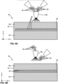
- FIG. 1 is a conceptual diagram illustrating a cross-sectional view of an example article 10 that includes a substrate 12 coated with an abradable coating 14.
- abradable coating 14 includes a plurality of microspheres 18 and a matrix material 16 and is on a surface 19 of substrate 12.
- Article 10 is a turbine blade track or a turbine blade shroud component of a high temperature mechanical system, namely a gas turbine engine or the like.
- Substrate 12 may include a metal alloy that includes silicon, a ceramic, or a ceramics matrix composite (CMC).
- the ceramic may be substantially homogeneous.
- a substrate 12 that includes a ceramic includes, for example, a Si-containing ceramic, such SiO 2 , silicon carbide (SiC) or silicon nitride (Si 3 N 4 ); Al 2 O 3 ; aluminosilicate (e.g., Al 2 SiO 5 ); or the like.
- substrate 12 includes a metal alloy that includes Si, such as a molybdenum-silicon alloy (e.g., MoSi 2 ) or a niobium-silicon alloy (e.g., NbSi 2 ).
- a metal alloy that includes Si such as a molybdenum-silicon alloy (e.g., MoSi 2 ) or a niobium-silicon alloy (e.g., NbSi 2 ).
- substrate 12 includes a matrix material and a reinforcement material.
- the matrix material includes a ceramic material, such as, for example, SiC, Si 3 N 4 , Al 2 O 3 , aluminosilicate, SiO 2 , or the like.
- the CMC further includes a continuous or discontinuous reinforcement material.
- the reinforcement material may include discontinuous whiskers, platelets, or particulates.
- the reinforcement material may include a continuous monofilament or multifilament weave.
- Article 10 further includes abradable coating 14, which in the example of FIG. 1 is directly on surface 19 of substrate 12.
- Abradable coating 14 includes a plurality of microspheres 18 and a matrix material 16.
- Matrix material 16 may include at least one of a rare earth silicate, a stabilized zirconium oxide, mullite, or BSAS. In some examples, matrix material 16 includes at least one rare earth silicate.
- the plurality of microspheres 18 possesses a visual characteristic that, under visual or UV-assisted inspection, is distinct from a visual characteristic of matrix material 16.
- the plurality of microspheres includes microspheres including at least one rare earth silicate, at least one rare earth oxide, or at least one rare earth silicate and at least one rare earth oxide, and may include a composition different from the composition of matrix material 16.
- the at least one rare earth silicate, the at least one rare earth oxide, or the at least one rare earth silicate and the at least one rare earth oxide is present in the microspheres in a glass phase.
- the at least one rare earth silicate, the at least one rare earth oxide, or the at least one rare earth silicate and the at least one rare earth oxide is present in the microspheres in a crystalline or semi-crystalline phase.
- the rare earth silicate may include at least one of yttrium monosilicate (Y 2 SiO 5 ), yttrium disilicate (Y 2 Si 2 O 7 ), ytterbium monosilicate (Yb 2 SiO 5 ), ytterbium disilicate (Yb 2 Si 2 O 7 ), erbium monosilicate (Er 2 SiO 5 ), erbium disilicate (Er 2 Si 2 O 7 ), neodymium monosilicate (Nd 2 SiO 5 ), neodymium disilicate (Nd 2 Si 2 O 7 ), gadolinium monosilicate (Gd 2 SiO 5 ), or gadolinium disilicate (Gd 2 Si 2 O 7 ).
- the rare earth oxide may include at least one of yttrium oxide (Y 2 O 3 ), ytterbium oxide (Yb 2 C 3 ), erbium oxide (ErO 3 ), neodymium oxide (Nd 2 O 3 ), or gadolinium oxide (Gd 2 C 3 ).
- the plurality of microspheres 18 may be substantially solid or may be hollow.
- the plurality of microspheres may include a ceramic oxide and the at least one rare earth silicate, the at least one rare earth oxide, or the at least one rare earth silicate and at least one rare earth oxide.
- the plurality of microspheres may include aluminum oxide doped with yttrium oxide, yttrium monosilicate, or yttrium disilicate; or may include yttrium-aluminum-garnet (YAG) doped with ytterbium oxide, ytterbium monosilicate, or ytterbium disilicate.
- YAG yttrium-aluminum-garnet
- the plurality of microspheres 18 may fluoresce when exposed to UV radiation.
- the plurality of microspheres 18 may include at least one of yttrium monosilicate (Y 2 SiO 5 ), yttrium disilicate (Y 2 Si 2 O 7 ), ytterbium monosilicate (Yb 2 SiO 5 ), or ytterbium disilicate (Yb 2 Si 2 O 7 ), all of which may fluoresce when exposed to UV radiation.
- the plurality of microspheres 18 possesses a visual characteristic observable in the visible wavelengths that is different from a visual characteristic of matrix material 16.
- the color of the plurality of microspheres 18 may be different than the color of matrix materials.
- the plurality of microspheres 18 may include at least one of erbium monosilicate (Er 2 SiO 5 ), erbium disilicate (Er 2 Si 2 O 7 ), neodymium monosilicate (Nd 2 SiO 5 ), neodymium disilicate (Nd 2 Si 2 O 7 ), gadolinium monosilicate (Gd 2 SiO 5 ), or gadolinium disilicate (Gd 2 Si 2 O 7 ).
- erbium monosilicate Er 2 SiO 5
- Er 2 Si 2 O 7 erbium disilicate
- Nd 2 SiO 5 neodymium monosilicate
- Nd 2 Si 2 O 7 neodymium disilicate
- Gd 2 SiO 5 gadolinium monosilicate
- Gd 2 Si 2 O 7 gadolinium disilicate
- the plurality of microspheres 18 may include at least one dopant.
- the at least one dopant may include at least one element from the Lanthanide series of the periodic table (excluding ytterbium).
- the dopant may include at least one of lanthanum (La), cerium (Ce), praseodymium (Pr), neodymium (Nd), promethium (Pm), samarium (Sm), europium (Eu), gadolinium (Gd), terbium (Tb), dysprosium (Dy), holmium (Ho), erbium (Er), thulium (Tm), or lutetium (Lu).
- the plurality of microspheres 18 may include between about 0.1 atomic percent (at. %) and about 10 at. % of the at least one dopant.
- the plurality of microspheres 18 may include a mean diameter, median diameter, or the like, that is less than a thickness of the layer in which the plurality of microspheres 18 are located.
- the plurality of microspheres 18 may have a mean diameter, median diameter, or the like, that is less than the thickness of abradable coating 14 (measured in the y-axis direction of FIG. 1 , where orthogonal x-y-z axes are shown for ease of description only).
- the plurality of microspheres 18 may include a mean diameter, median diameter, or the like, that is less than 1000 micrometers (e.g., between 1 micrometer and 1000 micrometer), or less than about 100 micrometers (e.g., between 1 micrometer and 100 micrometer). In some examples, at least some microspheres of plurality of microspheres 18 may have a diameter less than a mean or median diameter of pores in abradable coating 14.
- the plurality of microspheres 18 is located at a predetermined depth from an outer surface 17 of abradable coating 14.
- the predetermined depth may be a substantially consistent (e.g., consistent or nearly consistent) depth from surface 19 of substrate 12.
- the remaining thickness of abradable coating 14 at that location may be determined by observing the microspheres 18 and knowing the distance (e.g., in the y-axis direction of FIG. 1 ) between the plurality of microspheres 18 and surface 19 of substrate 12.
- this may facilitate at least one of determination of a remaining life of abradable coating 14, determination of a size, depth, or both of damage to abradable coating 14, and removal and repair of abradable coating 14 to maintain clearances between abradable coating 14 and substrate 12 below a predetermined level to maintain a desired efficiency level of the gas turbine engine.
- abradable coating 14 defines a thickness, measured in a direction substantially normal to surface 19 of substrate 12 (e.g., measured in the y-axis direction of FIG. 1 ), between about 0.508 millimeters (about 0.02 inch) and about 2.032 mm (about 0.08 inch).
- the thickness of abradable coating 14 may be selected to be sufficient to allow abrasion of a portion of abradable coating 14 by a gas turbine engine blade without the blade contacting substrate 12.
- Abradable coating 14 is formed as a porous structure, which may facilitate abrasion of a portion of abradable coating 14 upon contact with a gas turbine engine blade or another moving component with which abradable coating 14 forms a seal.
- the abradable coating 14 includes porosity between about 25 vol. % and about 50 vol. %. In some examples, abradable coating 14 includes a porosity between about 35 vol. % and about 45 vol. %, or a porosity of about 40 vol. %.
- Porosity of abradable coating 14 may be defined as a volume of pores or cracks in abradable coating 14 divided by a total volume of abradable coating 14 (including both the volume of material in abradable coating 14 and the volume of pores/cracks in abradable coating 14).
- the porosity of abradable coating 14 may be controlled to vary throughout at least a portion of abradable coating 14. For example, the porosity of abradable coating 14 may be controlled to be lower in a portion of abradable coating 14 closer to surface 19 of substrate 12 and greater in a portion of abradable coating 14 further from surface 19 of substrate 12.
- Abradable coating 14 may be formed over or formed directly on substrate 12 using, for example, a thermal spraying technique, such as, for example, air plasma spraying, as described in further detail with reference to FIGS. 5A and 5B .
- Abradable coating 14 including matrix material 16 and plurality of microspheres 18 facilitates visual inspection of a thickness of abradable coating 14 by including the plurality of microspheres 18 at a predetermined depth within the thickness of abradable coating 14. In some examples, this visual inspection may occur at room temperature.
- the plurality of microspheres 18 possesses a visual characteristic under visual or UV-assisted inspection (e.g., color or fluorescence) that is distinct from a visual characteristic of matrix material 16.
- this may facilitate at least one of determination of a remaining life of the abradable coating 14, determination of a size, depth, or both of damage to abradable coating 14, or removal and repair of the abradable coating to maintain clearances between the abradable coating 14 and a blade tip below a predetermined level to maintain a desired efficiency level of the gas turbine engine.
- an abradable coating may include a plurality of layers, and at least one of the layers may be an abradable layer including a matrix material and a plurality of microspheres.
- FIG. 2 is a conceptual cross-sectional diagram illustrating another example article 20 that includes an example abradable coating including a plurality of microspheres.
- article 20 that includes a substrate 12, an optional bond layer 22 on a surface 19 of substrate 12, an optional environmental barrier coating (EBC) 24 on bond layer 22, a first abradable layer 26 on EBC 24, a second abradable layer 28 on first abradable layer 26, and a third abradable layer 29 on second abradable layer 28.
- second abradable layer 28 includes a plurality of microspheres 18 and a matrix material 16.
- Article 20 may be similar to or substantially the same as article 10 of FIG. 1 , as described above.
- Article 20 is a turbine blade track or a turbine blade shroud component of a high temperature mechanical system, namely a gas turbine engine.
- Substrate 12 may be similar to or substantially the same as substrate 12 of FIG. 1 , as described above.
- substrate 12 may include a metal alloy that includes silicon, a ceramic, or a CMC.
- article 20 may include a bond layer 22 on substrate 12. Although not illustrated in FIG. 1 , in other embodiments, article 20 may not include a bond layer 16.
- Bond layer 16 may improve adhesion between substrate 12 and the layer overlying bond layer 16 (e.g., second abradable layer 28 in FIG. 2 ).
- Bond layer 22 may include any useful material that improves adhesion between substrate 12 and an overlying layer.
- bond layer 16 may include silicon. Regardless of the composition of bond layer 22, bond layer 22 may have a thickness of between about 25.4 micrometers ( ⁇ m, about 0.001 inch) and about 254 ⁇ m (about 0.01 inch).
- Bond layer 22 may be formed on substrate 12 using, for example, plasma spraying, physical vapor deposition (PVD), electron beam physical vapor deposition (EB-PVD), directed vapor deposition (DVD), chemical vapor deposition (CVD), cathodic arc deposition slurry process deposition, sol-gel process deposition, electrophoretic deposition, or the like.
- PVD physical vapor deposition
- EB-PVD electron beam physical vapor deposition
- DVD directed vapor deposition
- CVD chemical vapor deposition
- cathodic arc deposition slurry process deposition sol-gel process deposition
- electrophoretic deposition electrophoretic deposition
- article 10 does not include bond layer 22.
- optional EBC 24 may be formed directly on substrate 12.
- Article 10 may not include bond layer 22 when the layer on substrate 12 and substrate 12 are sufficiently chemically and/or mechanically compatible.
- article 10 may not include bond layer 22.
- the coefficients of thermal expansion of substrate 12 and EBC 24 are sufficiently similar, article 10 may not include bond layer 22.
- EBC 24 is on bond layer 22 and is optional. EBC 24 may reduce or substantially prevent attack of bond layer 22 and/or substrate 12 by chemical species present in the environment in which article 10 is utilized, e.g., in the intake gas or exhaust gas of a gas turbine engine.
- EBC 24 may include a material that is resistant to oxidation or water vapor attack.
- EBC 24 may include, for example, at least one of mullite; a glass ceramic such as barium strontium aluminosilicate (BaO-SrO-Al 2 O 3 -2SiO 2 ; BSAS), calcium aluminosilicate (CaAl 2 Si 2 Os; CAS), cordierite (magnesium aluminosilicate), and lithium aluminosilicate; or a rare earth silicates (silicates of Lu, Yb, Tm, Er, Ho, Dy, Tb, Gd, Eu, Sm, Pm, Nd, Pr, Ce, La, Y, or Sc).
- barium strontium aluminosilicate BaO-SrO-Al 2 O 3 -2SiO 2
- BSAS barium strontium aluminosilicate
- CaAl 2 Si 2 Os calcium aluminosilicate
- cordierite magnesium aluminosilicate
- the rare earth silicate may be a rare earth mono-silicate (RE 2 SiO 5 , where RE stands for "rare earth”) or a rare earth di-silicate (RE 2 Si 2 O 7 , where RE stands for "rare earth”).
- EBC 24 is formed as a substantially non-porous layer, while in other examples, EBC 24 is formed as a layer that includes a plurality of cracks or pores.
- EBC 24 may define a thickness, measured in a direction substantially normal to surface 19 of substrate 12, between 25.4 ⁇ m (about 0.001 inch) and 508 ⁇ m (about 0.02 inch).
- EBC 24 may be formed using, for example, CVD; PVD, including EB-PVD and DVD; plasma spraying or another thermal spraying process; or the like.
- First abradable layer 26 is on optional EBC 24. When article 20 does not include EBC 24, first abradable layer 26 may be on bond layer 22 or substrate 12 (when both EBC 24 and bond layer 22 are omitted). First abradable layer 26 may include a composition similar to or substantially the same (e.g., the same or nearly the same) as matrix material 16 of FIG. 1 . For example, first abradable layer 26 may include at least one of a rare earth silicate, a stabilized zirconium oxide, mullite, or BSAS. First abradable layer 26 defines a thickness, measured in a direction substantially normal to surface 19 of substrate 12, between about 25.4 ⁇ m (about 0.001 inch) and about 2.032 mm (about 0.08 inch).
- First abradable layer 26 may be porous. In some examples, first abradable layer 26 includes porosity between about 25 vol. % and about 50 vol. %. In other examples, first abradable layer 26 includes porosity between about 35 vol. % and about 45 vol. %, or about 40 vol. %. In some examples, the porosity of first abradable layer 26 may be controlled to vary throughout at least a portion of first abradable layer 26. For example, the porosity of abradable layer may be controlled to be lower in a portion of first abradable layer 26 closer to a surface of substrate 12 and greater in a portion of abradable layer further from the surface of substrate 12.
- Second abradable layer 28 is on first abradable layer 26.
- Second abradable layer 28 may be similar to or substantially the same (e.g., the same or nearly the same) as abradable coating 14 of FIG. 1 .
- the composition of second abradable layer 28 may include plurality of microspheres 18 and matrix material 16.
- Plurality of microspheres 18 may be similar to or substantially the same (e.g., the same or nearly the same) as plurality of microspheres 18 of FIG. 1 .
- matrix material 16 may be similar to or substantially the same (e.g., the same or nearly the same) as matrix material 16 of FIG. 1 .
- Matrix material 16 may be same or different than the material in first abradable layer 26.
- Second abradable layer 28 defines a thickness, measured in a direction substantially normal to surface 19 of substrate 12, between about 25.4 ⁇ m (about 0.001 inch) to about 2.032 mm (about 0.08 inch). Second abradable layer 28 may be formed as a porous structure. In some examples, second abradable layer 28 includes porosity between about 25 vol. % and about 50 vol. %. In other examples, second abradable layer 28 includes porosity between about 35 vol. % and about 45 vol. %, or about 40 vol. %. Similar to first abradable layer 26, in some examples, the porosity of second abradable layer 28 may be controlled to vary throughout the thickness of second abradable layer 28.
- Third abradable layer 29 is on second abradable layer 28.
- the composition of third abradable layer 29 may be similar to or substantially the same as first abradable layer 26, matrix material 16 in second abradable layer 28, or both.
- the composition of third abradable layer 29 may be different than the composition of at least one of first abradable layer 26 and matrix material 16.
- third abradable layer 29 may include at least one of a rare earth silicate, a stabilized zirconium oxide, mullite, or BSAS. Similar to first abradable layer 26 and second abradable layer 28, third abradable layer 29 may define a thickness between about 25.4 ⁇ m (about 0.001 inch) to about 2.032 mm (about 0.08 inch).
- Third abradable layer 29 also may be porous, and may have a porosity between about 25 vol. % and about 50 vol. %, between about 35 vol. % and about 45 vol. %, or about 40 vol. %.
- Second abradable layer 28, and, more particularly, the plurality of microspheres 18, may be positioned within coating 25 at a predetermined depth from outer surface 27 of coating 25.
- the predetermined depth may be determined based at least in part on a clearance between a blade tip and substrate 12.
- Second abradable layer 28 may facilitate visual determination of a thickness of second abradable layer 28 by including the plurality of microspheres 18 at a predetermined depth within the thickness of the coating 25.
- the visual inspection of coating 25 may occur at room temperature.
- the plurality of microspheres 18 possesses a visual characteristic under visual or UV-assisted inspection (e.g., color or fluorescence) that is distinct from a visual characteristic of matrix material 16. In some examples, this may facilitate at least one of determination of a remaining life of coating 25, determination of a size, depth, or both of damage to coating 25, or removal and repair of the abradable coating to maintain clearances between coating 25 and a blade tip below a predetermined level to maintain a desired efficiency level of the gas turbine engine.
- FIG. 3 is a conceptual diagram illustrating a cross-sectional view of an example article 30 that includes a substrate 12, a bond layer 22, an EBC 24, a first abradable layer 26, a second abradable layer 38, and a third abradable layer 29.
- second abradable layer 38 includes a first plurality of microspheres 18, a second plurality of microsphere 32, and a matrix material 16.
- Article 30 of FIG. 3 may be similar to or substantially the same as article 20 illustrated in and described with respect to FIG. 2 , aside from the differences described herein. Unlike article 20 in FIG. 2 , article 30 of FIG. 3 includes a second abradable layer 38 that includes first plurality of microspheres 18, second plurality of microspheres 32, and matrix material 16.
- First plurality of microspheres 18 and second plurality of microspheres 32 may be similar to or substantially the same as plurality of microspheres 18 of FIG. 1 .
- first plurality of microspheres 18 and second plurality of microspheres 32 include at least one rare earth silicate, at least one rare earth oxide, or at least one rare earth silicate and at least one rare earth oxide.
- the composition of first plurality of microspheres 18 may be different than the composition of second plurality of microspheres 32.
- first plurality of microspheres 18 may include a first rare earth silicate
- second plurality of microspheres 32 may include a second, different rare earth silicate.
- First plurality of microspheres 18 may be located at a first predetermined depth from an outer surface 36 of coating 34.
- second plurality of microspheres 32 may be located at a second predetermined depth from outer surface 36.
- the first and second predetermined depth are different from each other.
- First plurality of microspheres 18 possesses a visual characteristic under visual or UV-assisted inspection that is distinct from a visual characteristic of matrix material 16 and a visual characteristic of second plurality of microspheres 32.
- Coating 34 illustrated in FIG. 3 which includes first and second plurality of microspheres 18, 32 facilitates visual determination of a thickness of second abradable layer 28 at two predetermined depths within the thickness of coating 34.
- the plurality of microspheres may be used to determine a remaining thickness of coating 34.
- a coating including microspheres located at multiple, different depths from outer surface 36 may facilitate more precise determination of the remaining thickness of coating 34.
- FIG. 3 illustrates an example in which second abradable layer 38 includes two types of microspheres 18 and 32, in other examples, second abradable layer 38 may include more than two types of microspheres.
- second abradable layer 38 may include a plurality of types of microspheres or at least two types of microspheres.
- first plurality of microspheres 18 and second plurality of microspheres 32 are disposed within the same layer of coating 34 (second abradable layer 38). In other examples, first plurality of microspheres 18 and second plurality of microspheres 32 may be disposed in different layers of a coating.
- FIG. 4 is a conceptual cross-sectional diagram illustrating another example article 40 that includes an example coating 48 including a plurality of microspheres.
- Article 40 includes a substrate 12, a bond layer 22 on substrate 12, an EBC 24 on bond layer 22, a first abradable layer 26 on EBC 24, a second abradable layer 28 on first abradable layer 26, a third abradable layer 44 on second abradable layer 44, and a fourth abradable layer 29 on third abradable layer 44.
- Article 40 of FIG. 4 may be similar to or substantially the same as article 20 illustrated in and described with respect to FIG. 2 , aside from the differences described herein.
- second abradable coating 28 includes a first plurality of microspheres 18 and a matrix material
- third abradable layer 44 includes a second plurality of microspheres 42 and a matrix material 46.
- First plurality of microspheres 18 and second plurality of microspheres 42 may be similar to or substantially the same as plurality of microspheres 18 of FIG. 1 .
- first plurality of microspheres 18 and second plurality of microspheres 42 may include at least one rare earth silicate.
- the composition of first plurality of microspheres 18 may be different than the composition of second plurality of microspheres 42.
- first plurality of microspheres 18 may include a first rare earth silicate
- second plurality of microspheres 42 may include a second, different rare earth silicate.
- First plurality of microspheres 18 may be located in second abradable layer 28 at a first predetermined depth from an outer surface 50 of coating 48. As shown in FIG.
- second plurality of microspheres 42 may be located in third abradable layer 44 at a second predetermined depth from outer surface 50.
- the first and second predetermined depths are different from each other.
- First plurality of microspheres 18 possesses a visual characteristic under visual or UV-assisted inspection that is distinct from a visual characteristic of matrix material 16 and second plurality of microspheres 42 possesses a visual characteristic that is distinct from a visual characteristic of matrix material 46.
- the visual characteristic of first plurality of microspheres 18 is different from the visual characteristic of second plurality of microspheres 42.
- Coating 48 illustrated in FIG. 4 which includes first and second plurality of microspheres 18 and 42 facilitates visual determination of a thickness of coating 48 at two predetermined depths within the thickness of coating 48. As described above, the plurality of microspheres may be used to determine a remaining thickness of the coating 48. A coating 48 including microspheres located at multiple, different depths from outer surface 50 may facilitate more precise determination of the remaining thickness of coating 48.
- FIG. 4 illustrates an example in which coating 48 includes two abradable layers 28 and 44 including a respective plurality of microspheres 18 and 42, in other examples, coating 48 may include more than two layers including microspheres. For example, coating 48 may include a plurality of layers including microspheres or at least two layers including microspheres.
- FIGS. 5A and 5B are conceptual diagrams illustrating example techniques for forming an abradable coating 14 including a plurality of microspheres 18 using air plasma spraying.
- an article 10 includes an abradable coating 14 on surface 19 of substrate 12.
- Abradable coating 14 includes a plurality of microspheres 18 and a matrix material 16.
- the APS technique may utilize an APS gun 52 to spray plurality of microspheres 18 and matrix material 16 onto surface 19 of substrate 12.
- plurality of microspheres 18 and matrix material 16 in powder form may be mixed upstream of APS gun 52, then sprayed onto abradable coating 14.
- the plurality of microspheres 18 may be deformed during the APS technique when passed through the APS gun 52, e.g., due to softening or melting of the plurality of microspheres 18.
- the plurality of microspheres 18 and matrix material 16 may be mixed downstream of APS gun 52, as shown in FIG. 5B .
- FIG. 6 is a flow diagram illustrating an example technique for forming an example abradable coating including a plurality of microspheres.
- the technique of FIG. 6 will be described with respect to article 20 of FIG. 2 .
- the technique of FIG. 6 may be used to form other articles, and article 20 of FIG. 2 may be formed using other techniques.
- the technique optionally includes forming bond layer 22 on substrate 12 (62).
- Bond layer 22 may be formed on substrate 12 using plasma spraying; PVD, such as EB-PVD or DVD; CVD; cathodic arc deposition; slurry deposition; sol-gel deposition; electrophoretic deposition; or the like.
- article 20 does not include bond layer 22, and the technique of FIG. 6 does not include forming bond layer 22 on substrate 12 (62).
- the technique also optionally includes forming EBC 24 on optional bond layer 22 (or substrate 12 if bond layer 22 is not present) (66).
- EBC 24 may be formed using, for example, CVD; PVD, including EB-PVD and DVD; plasma spraying or another thermal spraying process; or the like.
- article 20 does not include EBC 24, and the technique of FIG. 6 does not include forming EBC 24 on bond layer 22 (or substrate 12 if bond layer 22 is not present) (62).
- the technique of FIG. 6 also includes forming an optional first abradable layer 26 on EBC 24 (66).
- first abradable layer 26 also may be formed on bond layer 22 or substrate 12.
- first abradable layer 26 may be formed using, for example, a thermal spraying technique, such as air plasma spraying or the like.
- the technique of FIG. 6 also includes forming second abradable layer 28 on optional first abradable layer 26 (68).
- second abradable layer 28 also may be formed on EBC 24, bond layer 22, or substrate 12.
- second abradable layer 28 may be formed using air plasma spraying, such as one of the technique illustrated with respect to FIGS. 5A and 5B .
- plurality of microspheres 18 may be applied directly to the surface of the underlying layer (e.g., the surface of first abradable layer 26).
- the plurality of microspheres 18 may be deposited using slurry deposition or application of an adhesive loaded with the plurality of microspheres 18. After application of the plurality of microspheres, matrix material 16 is applied, e.g., using or slurry deposition, to form second abradable layerr28.
- third abradable layer 29 is formed on second abradable layer 28 (70).
- third abradable layer 29 may be formed using, for example, a thermal spraying technique, such as air plasma spraying or the like.
- a coating may include a plurality of layers within the coating that each have distinct visual characteristics compared to surrounding layers.
- FIG. 7 is a conceptual cross-sectional diagram illustrating another example article that includes an example coating 88 including a neodymium silicate layer, an erbium silicate layer, and a gadolinium silicate layer.
- Article 80 of FIG. 7 may be similar to or substantially the same as article 20 illustrated in and described with respect to FIG. 2 , aside from the differences described herein.
- substrate 12, bond layer 22, EBC 24, and first abradable layer 26, may be similar to or substantially the same as the corresponding structures described with respect to FIG. 2 .
- Second abradable layer 92 may be similar to or substantially the same as third abradable layer 29 in FIG. 2 .
- article 80 of FIG. 7 includes at least one neodymium silicate layer 82, at least one erbium silicate layer 84, and at least one gadolinium silicate layer 86.
- At least one neodymium silicate layer 82, at least one erbium silicate layer 84, and at least one gadolinium silicate layer 86 are between first abradable layer 26 and second abradable layer 92.
- FIG. 7 illustrates at least one gadolinium silicate layer 86 on at least one erbium silicate layer 84 and at least one erbium silicate layer 84 on at least one neodymium silicate layer 82, in other examples, the order of these layers may be changed into any order.
- coating 88 may include more than one of at least one neodymium silicate layer 82, more than one of at least one erbium silicate layer 84, or more than one of at least one gadolinium silicate layer 86. In some examples, coating 88 may include multiple sets of at least one neodymium silicate layer 82, at least one erbium silicate layer 84, and at least one gadolinium silicate layer 86.
- coating 88 may include a different numbers of the at least one neodymium silicate layer 82, at least one erbium silicate layer 84, and at least one gadolinium silicate layer 86 (e.g., more neodymium silicate layers 82 than erbium silicate layers 84 and gadolinium silicate layers 86, or the like).
- At least one neodymium silicate layer 82 may include neodymium monosilicate or neodymium disilicate.
- At least one erbium silicate layer 84 may include erbium monosilicate or erbium disilicate.
- At least one gadolinium silicate layer 86 may include gadolinium monosilicate, or gadolinium disilicate.
- the erbium monosilicate, erbium disilicate, neodymium monosilicate, neodymium disilicate, gadolinium monosilicate, or gadolinium disilicate may be doped with between about 0.1 at. % and about 10 at. % of an element selected from the Lanthanide series of the periodic table, excluding ytterbium.
- At least one neodymium silicate layer 82, at least one erbium silicate layer 84, and at least one gadolinium silicate layer 86 may be located at respective a predetermined depths from an outer surface 90 of coating 88.
- at least one neodymium silicate layer 82, at least one erbium silicate layer 84, and at least one gadolinium silicate layer 86 each defines a thickness, measured in a direction substantially normal to surface 19 of substrate 12, of between about 25.4 ⁇ m (about 0.001 inch) and about 2.032 mm (about 0.08 inch).
- the thicknesses of at least one neodymium silicate layer 82, at least one erbium silicate layer 84, and at least one gadolinium silicate layer 86 may be the same or may be different.
- the positions and thicknesses of at least one neodymium silicate layer 82, at least one erbium silicate layer 84, and at least one gadolinium silicate layer 86 may be determined from clearance requirements between the blade and seal segment (or blade track), such that the layers 82, 84, and 86 are located at a depth from surface 90 that approximate corresponds to an depth to which coating 88 is abraded during use.
- At least one neodymium silicate layer 82, at least one erbium silicate layer 84, and at least one gadolinium silicate layer 86 may be applied by APS or by physical vapor deposition (e.g., EB-PVD, DVD, or the like).
- Each of layers 82, 84, and 86 possesses a distinct visual characteristic (e.g., color) that is different than a visual characteristic of an adjacent layer.
- Layers 82, 84, and 86 may facilitate visual inspection of a thickness of coating 88 by including the plurality of layers 82, 84, and 86 at a predetermined depth within the thickness of coating 88. In some examples, this visual inspection may occur at room temperature.
- Coating 88 which includes a plurality of layers 82, 84, and 86 (e.g., at least three) located at multiple, different depths from outer surface 88, may facilitate more precise determination of the remaining thickness of coating 88.
- this may facilitate at least one of determination of a remaining life of the coating 88, determination of a size, depth, or both of damage to coating 88, or removal and repair of coating 88 to maintain clearances between coating 88 and a blade tip below a predetermined level to maintain a desired efficiency level of the gas turbine engine.
- the subject matter described herein may be applied to coatings of other types, such as abrasive coatings, thermal barrier coatings, environmental barrier coatings, self-lubricating coatings, or the like.
- the layer structure and compositions may differ for these different applications, but layers including a plurality of microspheres in a matrix material or a plurality of layers with distinct visual characteristics may also be used in these other coating systems.
Landscapes
- Chemical & Material Sciences (AREA)
- Engineering & Computer Science (AREA)
- Materials Engineering (AREA)
- Organic Chemistry (AREA)
- Ceramic Engineering (AREA)
- Mechanical Engineering (AREA)
- Inorganic Chemistry (AREA)
- Metallurgy (AREA)
- Chemical Kinetics & Catalysis (AREA)
- Structural Engineering (AREA)
- Physics & Mathematics (AREA)
- Plasma & Fusion (AREA)
- General Engineering & Computer Science (AREA)
- Manufacturing & Machinery (AREA)
- General Chemical & Material Sciences (AREA)
- General Physics & Mathematics (AREA)
- Life Sciences & Earth Sciences (AREA)
- Wood Science & Technology (AREA)
- Turbine Rotor Nozzle Sealing (AREA)
- Coating By Spraying Or Casting (AREA)
- Investigating Materials By The Use Of Optical Means Adapted For Particular Applications (AREA)
Claims (15)
- System, umfassend:eine Turbinenschaufellaufbahn oder eine Turbinenschaufelummantelung (10), die ein Substrat (12) umfasst; undeine Beschichtung auf dem Substrat (12), wobei die Beschichtung zumindest eine abreibbare Schicht (14) umfasst, wobei die zumindest eine abreibbare Schicht (14) porös ist, wobei die zumindest eine abreibbare Schicht (14) ein Matrixmaterial (16) und eine Vielzahl von Mikrokugeln (18) umfasst, die sich innerhalb der zumindest einen abreibbaren Schicht (14) in einer vorbestimmten Tiefe von einer Außenfläche (17) der Beschichtung befinden, wobei die Vielzahl von Mikrokugeln (18) eine visuelle Eigenschaft definiert, die sich von dem Matrixmaterial (16) unterscheidet, und wobei die Vielzahl von Mikrokugeln (18) zumindest ein Seltenerdoxid, zumindest ein Seltenerdsilikat oder zumindest ein Seltenerdoxid und zumindest ein Seltenerdsilikat umfasst; undeine Gasturbinenschaufel, wobei die Gasturbinenschaufel konfiguriert ist, um einen Teil der zumindest einen abreibbaren Schicht (14) auf dem Substrat (12) während Drehung der Gasturbinenschaufel zu kontaktieren, und wobei die zumindest eine abreibbare Schicht (14) konfiguriert ist, um zu zumindest der vorbestimmten Tiefe durch den Kontakt durch die Gasturbinenschaufel abgerieben zu werden.
- System nach Anspruch 1, wobei die zumindest eine abreibbare Schicht (14) eine erste abreibbare Schicht (26) und eine zweite abreibbare Schicht (28) umfasst, wobei die zweite abreibbare Schicht (28) auf der ersten abreibbaren Schicht (26) ist, wobei die zweite abreibbare Schicht (28) die Vielzahl von Mikrokugeln (18) umfasst und wobei die erste abreibbare Schicht (26) keine Mikrokugeln umfasst.
- System nach Anspruch 2, wobei die zumindest eine abreibbare Schicht (14) ferner eine dritte abreibbare Schicht (29) umfasst, wobei die dritte abreibbare Schicht (29) auf der zweiten abreibbaren Schicht (28) ist und wobei die dritte abreibbare Schicht (29) keine Mikrokugeln umfasst.
- System nach einem der Ansprüche 1 bis 3, wobei die Vielzahl von Mikrokugeln (18) eine erste Vielzahl von Mikrokugeln (18) umfasst, die eine erste visuelle Eigenschaft definieren, die sich von dem Matrixmaterial (16) unterscheidet, wobei die zumindest eine abreibbare Schicht (38) ferner eine zweite Vielzahl von Mikrokugeln (32) umfasst, die eine zweite visuelle Eigenschaft definieren, die sich von dem Matrixmaterial (16) und der ersten visuellen Eigenschaft unterscheidet, wobei sich die erste Vielzahl von Mikrokugeln (18) innerhalb der zumindest einen abreibbaren Schicht (38) in einer ersten vorbestimmten Tiefe von einer Außenfläche (36) der Beschichtung befindet, und wobei sich die zweite Vielzahl von Mikrokugeln (32) innerhalb der zumindest einen abreibbaren Schicht (38) in einer zweiten, anderen vorbestimmten Tiefe von einer Außenfläche (36) der Beschichtung befindet.
- System nach einem der Ansprüche 1 bis 4, wobei die Vielzahl von Mikrokugeln (18) Mikrokugeln (18) umfasst, die zumindest eines von Yttriummonosilikat, Yttriumdisilikat, Ytterbiummonosilikat, Ytterbiumdisilikat, Erbiummonosilikat, Erbiumdisilikat, Neodymmonosilikat, Neodymdisilikat, Gadoliniummonosilikat oder Gadoliniumdisilikat umfassen.
- System nach Anspruch 5, wobei die Mikrokugeln (18), die zumindest das eine von Yttriummonosilikat, Yttriumdisilikat, Ytterbiummonosilikat, Ytterbiumdisilikat, Erbiummonosilikat, Erbiumdisilikat, Neodymmonosilikat, Neodymdisilikat, Gadoliniummonosilikat oder Gadoliniumdisilikat umfassen, ferner zwischen etwa 0,1 Atomprozent (Atom-%) und etwa 10 Atom-% eines Elements umfassen, das aus der Lanthanidenreihe des Periodensystems ausgewählt ist, ausgenommen Ytterbium.
- System nach Anspruch 1, wobei zumindest einige Mikrokugeln (18) aus der Vielzahl von Mikrokugeln (18) einen Durchmesser von weniger als einem mittleren Durchmesser von Poren in der zumindest einen abreibbaren Schicht (14) aufweisen.
- System nach Anspruch 1, wobei:die Vielzahl von Mikrokugeln eine erste Vielzahl von Mikrokugeln (18) umfasst;die vorbestimmte Tiefe eine erste vorbestimmte Tiefe umfasst;eine erste abreibbare Schicht (38) der zumindest einen abreibbaren Schicht (14) das Matrixmaterial (16) umfasst, sich die erste Vielzahl von Mikrokugeln (18) innerhalb der ersten abreibbaren Schicht (38) in der ersten vorbestimmten Tiefe von der Außenfläche (36) der Beschichtung befindet, und sich eine zweite Vielzahl von Mikrokugeln (32) innerhalb der ersten abreibbaren Schicht (38) in einer zweiten vorbestimmten Tiefe von der Außenfläche (36) der Beschichtung befindet, wobei sich die zweite vorbestimmte Tiefe von der ersten vorbestimmten Tiefe unterscheidet und wobei die zweite Vielzahl von Mikrokugeln (32) eine visuelle Eigenschaft aufweist, die sich von dem Matrixmaterial (16) und von der visuellen Eigenschaft der ersten Vielzahl von Mikrokugeln (18) unterscheidet.
- System nach Anspruch 1, wobei die vorbestimmte Tiefe basierend zumindest teilweise auf einem Abstand zwischen einer Schaufelspitze der Gasturbinentriebwerksschaufel und dem Substrat (12) bestimmt wird.
- Verfahren, umfassend:Bilden einer Beschichtung auf einem Substrat (12) einer Turbinenschaufellaufbahn oder einer Turbinenschaufelummantelung, wobei die Beschichtung zumindest eine abreibbare Schicht (14) umfasst, wobei die zumindest eine abreibbare Schicht (14) porös ist, wobei die zumindest eine abreibbare Schicht (14) ein Matrixmaterial (16) und eine Vielzahl von Mikrokugeln (18) umfasst, die sich innerhalb der zumindest einen abreibbaren Schicht (14) in einer vorbestimmten Tiefe von einer Außenfläche (17) der Beschichtung befinden, und wobei die Vielzahl von Mikrokugeln (18) eine visuelle Eigenschaft definiert, die sich von dem Matrixmaterial (16) unterscheidet, und wobei die Vielzahl von Mikrokugeln (18) zumindest ein Seltenerdoxid, zumindest ein Seltenerdsilikat oder zumindest ein Seltenerdoxid und zumindest ein Seltenerdsilikat umfasst; undKontaktieren eines Teils der zumindest einen abreibbaren Beschichtung (14) auf dem Substrat (12) mit einer Gasturbinenschaufel, wobei die zumindest eine abreibbare Schicht (14) konfiguriert ist, um auf zumindest die vorbestimmte Tiefe durch den Kontakt durch die Gasturbinenschaufel während Drehung der Gasturbinenschaufel abgerieben zu werden.
- Verfahren nach Anspruch 10, wobei das Bilden der Beschichtung auf dem Substrat (12) Luftplasmasprühen der zumindest einen abreibbaren Schicht (14) über dem Substrat (12) umfasst.
- Verfahren nach Anspruch 10, wobei das Bilden der Beschichtung auf dem Substrat (12) Folgendes umfasst:Aufbringen der Vielzahl von Mikrokugeln (18) auf eine Oberfläche einer ersten abreibbaren Schicht (26) der zumindest einen abreibbaren Schicht (14) mit einem Klebstoff; undAblagern des Matrixmaterials (16) um die Vielzahl von Mikrokugeln (18), um eine zweite abreibbare Schicht (28) zu bilden, die das Matrixmaterial (16) und die Vielzahl von Mikrokugeln (18) umfasst.
- Verfahren nach einem der Ansprüche 10 bis 12, wobei das Matrixmaterial (16) ein Seltenerdsilikat umfasst.
- Verfahren nach einem der Ansprüche 10 bis 13, wobei die Vielzahl von Mikrokugeln (18) Mikrokugeln (18) umfasst, die zumindest eines von Yttriummonosilikat, Yttriumdisilikat, Ytterbiummonosilikat, Ytterbiumdisilikat, Erbiummonosilikat, Erbiumdisilikat, Neodymmonosilikat, Neodymdisilikat, Gadoliniummonosilikat oder Gadoliniumdisilikat umfassen.
- Verfahren nach Anspruch 14, wobei die Mikrokugeln (18), die zumindest eines von Yttriummonosilikat, Yttriumdisilikat, Ytterbiummonosilikat, Ytterbiumdisilikat, Erbiummonosilikat, Erbiumdisilikat, Neodymmonosilikat, Neodymdisilikat, Gadoliniummonosilikat oder Gadoliniumdisilikat umfassen, ferner zwischen etwa 0,1 Atomprozent (Atom-%) und etwa 10 Atom-% eines Elements umfassen, das aus der Lanthanidenreihe des Periodensystems ausgewählt ist, ausgenommen Ytterbium.
Applications Claiming Priority (1)
| Application Number | Priority Date | Filing Date | Title |
|---|---|---|---|
| US201462020545P | 2014-07-03 | 2014-07-03 |
Publications (3)
| Publication Number | Publication Date |
|---|---|
| EP2962844A2 EP2962844A2 (de) | 2016-01-06 |
| EP2962844A3 EP2962844A3 (de) | 2016-04-13 |
| EP2962844B1 true EP2962844B1 (de) | 2024-09-04 |
Family
ID=54011500
Family Applications (1)
| Application Number | Title | Priority Date | Filing Date |
|---|---|---|---|
| EP15175074.2A Active EP2962844B1 (de) | 2014-07-03 | 2015-07-02 | Visueller beschichtungsdickenanzeiger |
Country Status (3)
| Country | Link |
|---|---|
| US (2) | US9556743B2 (de) |
| EP (1) | EP2962844B1 (de) |
| CA (1) | CA2895986C (de) |
Families Citing this family (34)
| Publication number | Priority date | Publication date | Assignee | Title |
|---|---|---|---|---|
| US10544732B2 (en) * | 2011-07-28 | 2020-01-28 | Pratt & Whitney Canada Corp. | Rotary internal combustion engine with removable subchamber insert |
| US9556743B2 (en) | 2014-07-03 | 2017-01-31 | Rolls-Royce Corporation | Visual indicator of coating thickness |
| US10501378B2 (en) | 2015-02-24 | 2019-12-10 | United Technologies Corporation | Conformal composite coatings and methods |
| CA2955646C (en) | 2016-01-19 | 2025-01-07 | Pratt & Whitney Canada Corp. | GAS TURBINE ROTOR BLADE HOUSING |
| US10544698B2 (en) * | 2016-06-20 | 2020-01-28 | United Technologies Corporation | Air seal abrasive coating and method |
| US10527524B2 (en) * | 2016-10-26 | 2020-01-07 | United Technologies Corporation | Method of inspecting component surface with marking media |
| US10428674B2 (en) | 2017-01-31 | 2019-10-01 | Rolls-Royce North American Technologies Inc. | Gas turbine engine features for tip clearance inspection |
| US20180311934A1 (en) * | 2017-04-28 | 2018-11-01 | Rolls-Royce Corporation | Seal coating for ceramic matrix composite |
| FR3072413B1 (fr) * | 2017-10-18 | 2020-08-21 | Safran Aircraft Engines | Element abradable de turbomachine |
| EP3784815A4 (de) * | 2018-04-27 | 2021-11-03 | Applied Materials, Inc. | Schutz von komponenten vor korrosion |
| DE102018208071A1 (de) | 2018-05-23 | 2019-11-28 | MTU Aero Engines AG | Verfahren zur beschichtung einer metallischen oberfläche |
| US11021989B2 (en) | 2018-07-18 | 2021-06-01 | Raytheon Technologies Corporation | Environmental barrier multi-phase abradable coating |
| FR3085172B1 (fr) * | 2018-08-22 | 2021-03-05 | Safran Aircraft Engines | Revetement abradable pour aubes tournantes d'une turbomachine |
| US11952317B2 (en) * | 2018-10-18 | 2024-04-09 | Rolls-Royce Corporation | CMAS-resistant barrier coatings |
| EP3670481A1 (de) * | 2018-12-21 | 2020-06-24 | Rolls-Royce Corporation | Wärme- und umweltsperrschichtsystem |
| FR3091548B1 (fr) * | 2019-01-09 | 2022-12-09 | Safran Aircraft Engines | Elément abradable de turbomachine pourvu de témoins d’usure visuels |
| FR3095045B1 (fr) | 2019-04-12 | 2021-12-10 | Safran Aircraft Engines | Procede de detection d’une aspérité sur une couche abradable dans un carter de soufflante |
| EP4378911A3 (de) * | 2019-09-20 | 2024-08-07 | RTX Corporation | Abreibbare turbinenmotorsysteme |
| US12344565B2 (en) * | 2019-12-19 | 2025-07-01 | Rolls-Royce Corporation | CMAS-resistant abradable coatings |
| US11686208B2 (en) | 2020-02-06 | 2023-06-27 | Rolls-Royce Corporation | Abrasive coating for high-temperature mechanical systems |
| US11326469B2 (en) | 2020-05-29 | 2022-05-10 | Rolls-Royce Corporation | CMCs with luminescence environmental barrier coatings |
| EP3926068A1 (de) | 2020-06-19 | 2021-12-22 | Rolls-Royce Corporation | Cmas-resistentes wärmedämmbeschichtungssystem |
| US12018572B2 (en) | 2020-06-19 | 2024-06-25 | Rolls-Royce Corporation | CMAS resistant environmental barrier coating system |
| US11313280B2 (en) * | 2020-07-16 | 2022-04-26 | Raytheon Technologies Corporation | Gas turbine engine including seal assembly with abradable coating and cutter |
| US11313281B2 (en) * | 2020-07-16 | 2022-04-26 | Raytheon Technologies Corporation | Gas turbine engine including seal assembly with abradable coating including magnetic particles |
| US11293351B2 (en) * | 2020-07-16 | 2022-04-05 | Raytheon Technologies Corporation | Gas turbine engine including seal assembly with abradable coating including magnetic particles embedded in polymer |
| US11566531B2 (en) | 2020-10-07 | 2023-01-31 | Rolls-Royce Corporation | CMAS-resistant abradable coatings |
| DE102021119428A1 (de) * | 2021-07-27 | 2023-02-02 | Polysecure Gmbh | Indikatorzusammensetzung zur Applikationskontrolle |
| CN114000090B (zh) * | 2021-10-15 | 2024-05-24 | 中国航发北京航空材料研究院 | 一种氧化物/氧化物复合材料表面环境障涂层的制备方法 |
| US11661855B2 (en) * | 2021-10-25 | 2023-05-30 | Raytheon Technologies Corporation | Low density hybrid knife seal |
| US11725517B1 (en) * | 2022-05-13 | 2023-08-15 | Raytheon Technologies Corporation | Airfoil tip cleaning and assessment systems and methods |
| US12442634B2 (en) | 2022-05-13 | 2025-10-14 | Rtx Corporation | Visual and/or dimensional tip inspection systems and methods |
| US20240166890A1 (en) * | 2022-11-21 | 2024-05-23 | Raytheon Technologies Corporation | Environmental barrier coating with thermal resistance |
| FR3163369A1 (fr) * | 2024-06-17 | 2025-12-19 | Safran Ceramics | Pièce comprenant un substrat et une barrière environnementale et procédés associés |
Citations (1)
| Publication number | Priority date | Publication date | Assignee | Title |
|---|---|---|---|---|
| WO2015126476A2 (en) * | 2013-12-12 | 2015-08-27 | General Electric Company | Method of depositing abradable coatings under polymer gels |
Family Cites Families (28)
| Publication number | Priority date | Publication date | Assignee | Title |
|---|---|---|---|---|
| JPS62207885A (ja) | 1986-03-07 | 1987-09-12 | Toshiba Corp | 高温耐熱部材 |
| US5270116A (en) | 1986-07-10 | 1993-12-14 | Minnesota Mining And Manufacturing Company | Process for fluorimetric monitoring of functional coatings and compositions and fluorescent agents therefor |
| US4922113A (en) | 1986-07-10 | 1990-05-01 | Minnesota Mining And Manufacturing Company | Process for fluorimetric monitoring of functional coatings and compositions and fluorescent agents therefor |
| US5187542A (en) | 1991-06-27 | 1993-02-16 | The United States Of America As Represented By The Administrator Of The National Aeronautics And Space Administration | Spectroscopic wear detector |
| AU5169098A (en) | 1997-11-07 | 1999-05-31 | Biotraces, Inc. | Method and apparatus for monitoring wear, corrosion, and related problems |
| WO2000006796A1 (en) | 1998-07-27 | 2000-02-10 | Imperial College Of Science, Technology And Medicine | Thermal barrier coating with thermoluminescent indicator material embedded therein |
| US6644917B2 (en) * | 2001-08-14 | 2003-11-11 | General Electric Company | Smart coating system with chemical taggants for coating condition assessment |
| GB0121312D0 (en) | 2001-09-04 | 2001-10-24 | Rolls Royce Plc | A temperature indicating paint |
| US6730918B2 (en) | 2001-12-20 | 2004-05-04 | General Electric Company | Apparatus for determining past-service conditions and remaining life of thermal barrier coatings and components having such coatings |
| US7270890B2 (en) | 2002-09-23 | 2007-09-18 | Siemens Power Generation, Inc. | Wear monitoring system with embedded conductors |
| US7221445B2 (en) | 2003-04-11 | 2007-05-22 | Metrolaser, Inc. | Methods and apparatus for detecting and quantifying surface characteristics and material conditions using light scattering |
| GB0319349D0 (en) * | 2003-08-18 | 2003-09-17 | Southside Thermal Sciences Sts | Coatings and an optical method for detecting corrosion processes in coatings |
| US8012374B2 (en) | 2004-11-04 | 2011-09-06 | The University Of Cincinnati | Slow-release inhibitor for corrosion control of metals |
| US7231817B2 (en) | 2005-01-18 | 2007-06-19 | Siemens Power Generation, Inc. | Inspection system for a turbine blade region of a turbine engine |
| US7968205B2 (en) | 2005-10-21 | 2011-06-28 | Shin-Etsu Chemical Co., Ltd. | Corrosion resistant multilayer member |
| US20100015442A1 (en) * | 2006-04-28 | 2010-01-21 | Jsr Corporation | Adhesive composition, method for producing the same and adhesive body |
| JP5436761B2 (ja) | 2007-06-15 | 2014-03-05 | 川崎重工業株式会社 | 炭化ケイ素系繊維強化セラミックス複合材料の耐環境コーティング構造 |
| US7619728B2 (en) | 2007-07-26 | 2009-11-17 | General Electric Company | Methods and systems for in-situ machinery inspection |
| JP5091642B2 (ja) | 2007-11-29 | 2012-12-05 | 三菱重工業株式会社 | 遮熱コーティングならびにこれを用いたガスタービン部品およびガスタービン |
| US20090162632A1 (en) * | 2007-12-19 | 2009-06-25 | Glen Harold Kirby | Barrier coatings comprising taggants and components comprising the same |
| US20090162533A1 (en) | 2007-12-19 | 2009-06-25 | Glen Harold Kirby | Methods allowing for improved inspection of components having a barrier coating |
| US8124252B2 (en) | 2008-11-25 | 2012-02-28 | Rolls-Royce Corporation | Abradable layer including a rare earth silicate |
| US20100154422A1 (en) * | 2008-12-19 | 2010-06-24 | Glen Harold Kirby | Cmas mitigation compositions, environmental barrier coatings comprising the same, and ceramic components comprising the same |
| FR2942267B1 (fr) | 2009-02-19 | 2011-05-06 | Turbomeca | Temoin d'erosion pour roue de compresseur |
| US8695445B2 (en) | 2011-05-09 | 2014-04-15 | General Electric Company | Wear-indicating system for use with turbine engines and methods of inspecting same |
| US8622016B2 (en) | 2011-10-04 | 2014-01-07 | Siemens Energy, Inc. | Wear indication system for compressor diaphragms of gas turbine engines |
| US9400171B2 (en) | 2012-04-05 | 2016-07-26 | Siemens Energy, Inc. | Optical wear monitoring |
| US9556743B2 (en) | 2014-07-03 | 2017-01-31 | Rolls-Royce Corporation | Visual indicator of coating thickness |
-
2015
- 2015-07-01 US US14/789,676 patent/US9556743B2/en active Active
- 2015-07-02 EP EP15175074.2A patent/EP2962844B1/de active Active
- 2015-07-02 CA CA2895986A patent/CA2895986C/en active Active
-
2016
- 2016-12-16 US US15/381,825 patent/US10550711B2/en active Active
Patent Citations (1)
| Publication number | Priority date | Publication date | Assignee | Title |
|---|---|---|---|---|
| WO2015126476A2 (en) * | 2013-12-12 | 2015-08-27 | General Electric Company | Method of depositing abradable coatings under polymer gels |
Non-Patent Citations (1)
| Title |
|---|
| MATEJICEK J ET AL: "Alternative methods for determination of composition and porosity in abradable materials", MATERIALS CHARACTERIZATION, ELSEVIER, NEW YORK, NY, US, vol. 57, no. 1, 1 July 2006 (2006-07-01), pages 17 - 29, XP027973787, ISSN: 1044-5803, [retrieved on 20060701] * |
Also Published As
| Publication number | Publication date |
|---|---|
| US20170101883A1 (en) | 2017-04-13 |
| US20160003092A1 (en) | 2016-01-07 |
| US10550711B2 (en) | 2020-02-04 |
| US9556743B2 (en) | 2017-01-31 |
| CA2895986C (en) | 2017-08-01 |
| EP2962844A2 (de) | 2016-01-06 |
| EP2962844A3 (de) | 2016-04-13 |
| CA2895986A1 (en) | 2016-01-03 |
Similar Documents
| Publication | Publication Date | Title |
|---|---|---|
| EP2962844B1 (de) | Visueller beschichtungsdickenanzeiger | |
| US9624583B2 (en) | Slurry-based coating techniques for smoothing surface imperfections | |
| CA2712248C (en) | Cmas-resistant thermal barrier coatings | |
| EP2189504B1 (de) | Verstärkte Oxidbeschichtungen | |
| US9194242B2 (en) | Thermal barrier coatings including CMAS-resistant thermal barrier coating layers | |
| EP2553027B1 (de) | Mehrlagige cmas-beständige sperrschicht | |
| US9713912B2 (en) | Features for mitigating thermal or mechanical stress on an environmental barrier coating | |
| EP1806435A2 (de) | Geschichtete Wärmedammchicht enthaltend lanthanideoxids für eine verbesserte Beständigkeit gegen CMAS | |
| CA2950548C (en) | Coating inspection method | |
| US11566531B2 (en) | CMAS-resistant abradable coatings | |
| US20090162561A1 (en) | Methods for making barrier coatings comprising taggants and components having the same | |
| US20230228199A1 (en) | Slotted ceramic coating with a reactive phase coating disposed thereon for improved cmas resistance and methods of forming the same | |
| GB2455852A (en) | Tagged environmental and thermal barrier coatings. | |
| GB2455850A (en) | Method for allowing for improved inspection of components having barrier coatings | |
| EP1577499A2 (de) | Turbinenkomponenten mit Wärmedämmschichten | |
| JP2006199574A (ja) | ケイ素含有材料用の、物理バリヤー層を有する環境バリヤーコーティング | |
| US11655543B2 (en) | CMAS-resistant barrier coatings | |
| CN112756232A (zh) | 修复涂层系统和方法 | |
| CA3148268A1 (en) | Coated components having environmental barrier coatings containing a rare earth disilicate and a second phase material | |
| US11326469B2 (en) | CMCs with luminescence environmental barrier coatings | |
| Lehmann et al. | Thermally sprayed thermal barrier coating (TBC) systems: a survey of recent patents |
Legal Events
| Date | Code | Title | Description |
|---|---|---|---|
| PUAI | Public reference made under article 153(3) epc to a published international application that has entered the european phase |
Free format text: ORIGINAL CODE: 0009012 |
|
| 17P | Request for examination filed |
Effective date: 20150702 |
|
| AK | Designated contracting states |
Kind code of ref document: A2 Designated state(s): AL AT BE BG CH CY CZ DE DK EE ES FI FR GB GR HR HU IE IS IT LI LT LU LV MC MK MT NL NO PL PT RO RS SE SI SK SM TR |
|
| AX | Request for extension of the european patent |
Extension state: BA ME |
|
| PUAL | Search report despatched |
Free format text: ORIGINAL CODE: 0009013 |
|
| AK | Designated contracting states |
Kind code of ref document: A3 Designated state(s): AL AT BE BG CH CY CZ DE DK EE ES FI FR GB GR HR HU IE IS IT LI LT LU LV MC MK MT NL NO PL PT RO RS SE SI SK SM TR |
|
| AX | Request for extension of the european patent |
Extension state: BA ME |
|
| RIC1 | Information provided on ipc code assigned before grant |
Ipc: C23C 4/12 20060101ALI20160310BHEP Ipc: F01D 5/28 20060101ALI20160310BHEP Ipc: G01B 11/06 20060101ALI20160310BHEP Ipc: B32B 18/00 20060101AFI20160310BHEP Ipc: C23C 4/10 20060101ALI20160310BHEP |
|
| STAA | Information on the status of an ep patent application or granted ep patent |
Free format text: STATUS: EXAMINATION IS IN PROGRESS |
|
| 17Q | First examination report despatched |
Effective date: 20171025 |
|
| GRAP | Despatch of communication of intention to grant a patent |
Free format text: ORIGINAL CODE: EPIDOSNIGR1 |
|
| STAA | Information on the status of an ep patent application or granted ep patent |
Free format text: STATUS: GRANT OF PATENT IS INTENDED |
|
| INTG | Intention to grant announced |
Effective date: 20240129 |
|
| GRAS | Grant fee paid |
Free format text: ORIGINAL CODE: EPIDOSNIGR3 |
|
| P01 | Opt-out of the competence of the unified patent court (upc) registered |
Free format text: CASE NUMBER: APP_34788/2024 Effective date: 20240610 |
|
| GRAA | (expected) grant |
Free format text: ORIGINAL CODE: 0009210 |
|
| STAA | Information on the status of an ep patent application or granted ep patent |
Free format text: STATUS: THE PATENT HAS BEEN GRANTED |
|
| AK | Designated contracting states |
Kind code of ref document: B1 Designated state(s): AL AT BE BG CH CY CZ DE DK EE ES FI FR GB GR HR HU IE IS IT LI LT LU LV MC MK MT NL NO PL PT RO RS SE SI SK SM TR |
|
| REG | Reference to a national code |
Ref country code: GB Ref legal event code: FG4D |
|
| REG | Reference to a national code |
Ref country code: CH Ref legal event code: EP |
|
| REG | Reference to a national code |
Ref country code: IE Ref legal event code: FG4D |
|
| REG | Reference to a national code |
Ref country code: DE Ref legal event code: R096 Ref document number: 602015089750 Country of ref document: DE |
|
| REG | Reference to a national code |
Ref country code: LT Ref legal event code: MG9D |
|
| REG | Reference to a national code |
Ref country code: NL Ref legal event code: MP Effective date: 20240904 |
|
| PG25 | Lapsed in a contracting state [announced via postgrant information from national office to epo] |
Ref country code: NO Free format text: LAPSE BECAUSE OF FAILURE TO SUBMIT A TRANSLATION OF THE DESCRIPTION OR TO PAY THE FEE WITHIN THE PRESCRIBED TIME-LIMIT Effective date: 20241204 |
|
| PG25 | Lapsed in a contracting state [announced via postgrant information from national office to epo] |
Ref country code: GR Free format text: LAPSE BECAUSE OF FAILURE TO SUBMIT A TRANSLATION OF THE DESCRIPTION OR TO PAY THE FEE WITHIN THE PRESCRIBED TIME-LIMIT Effective date: 20241205 Ref country code: FI Free format text: LAPSE BECAUSE OF FAILURE TO SUBMIT A TRANSLATION OF THE DESCRIPTION OR TO PAY THE FEE WITHIN THE PRESCRIBED TIME-LIMIT Effective date: 20240904 Ref country code: PL Free format text: LAPSE BECAUSE OF FAILURE TO SUBMIT A TRANSLATION OF THE DESCRIPTION OR TO PAY THE FEE WITHIN THE PRESCRIBED TIME-LIMIT Effective date: 20240904 |
|
| PG25 | Lapsed in a contracting state [announced via postgrant information from national office to epo] |
Ref country code: BG Free format text: LAPSE BECAUSE OF FAILURE TO SUBMIT A TRANSLATION OF THE DESCRIPTION OR TO PAY THE FEE WITHIN THE PRESCRIBED TIME-LIMIT Effective date: 20240904 |
|
| PG25 | Lapsed in a contracting state [announced via postgrant information from national office to epo] |
Ref country code: LV Free format text: LAPSE BECAUSE OF FAILURE TO SUBMIT A TRANSLATION OF THE DESCRIPTION OR TO PAY THE FEE WITHIN THE PRESCRIBED TIME-LIMIT Effective date: 20240904 |
|
| PG25 | Lapsed in a contracting state [announced via postgrant information from national office to epo] |
Ref country code: HR Free format text: LAPSE BECAUSE OF FAILURE TO SUBMIT A TRANSLATION OF THE DESCRIPTION OR TO PAY THE FEE WITHIN THE PRESCRIBED TIME-LIMIT Effective date: 20240904 |
|
| PG25 | Lapsed in a contracting state [announced via postgrant information from national office to epo] |
Ref country code: ES Free format text: LAPSE BECAUSE OF FAILURE TO SUBMIT A TRANSLATION OF THE DESCRIPTION OR TO PAY THE FEE WITHIN THE PRESCRIBED TIME-LIMIT Effective date: 20240904 Ref country code: RS Free format text: LAPSE BECAUSE OF FAILURE TO SUBMIT A TRANSLATION OF THE DESCRIPTION OR TO PAY THE FEE WITHIN THE PRESCRIBED TIME-LIMIT Effective date: 20241204 |
|
| PG25 | Lapsed in a contracting state [announced via postgrant information from national office to epo] |
Ref country code: RS Free format text: LAPSE BECAUSE OF FAILURE TO SUBMIT A TRANSLATION OF THE DESCRIPTION OR TO PAY THE FEE WITHIN THE PRESCRIBED TIME-LIMIT Effective date: 20241204 Ref country code: PL Free format text: LAPSE BECAUSE OF FAILURE TO SUBMIT A TRANSLATION OF THE DESCRIPTION OR TO PAY THE FEE WITHIN THE PRESCRIBED TIME-LIMIT Effective date: 20240904 Ref country code: NO Free format text: LAPSE BECAUSE OF FAILURE TO SUBMIT A TRANSLATION OF THE DESCRIPTION OR TO PAY THE FEE WITHIN THE PRESCRIBED TIME-LIMIT Effective date: 20241204 Ref country code: LV Free format text: LAPSE BECAUSE OF FAILURE TO SUBMIT A TRANSLATION OF THE DESCRIPTION OR TO PAY THE FEE WITHIN THE PRESCRIBED TIME-LIMIT Effective date: 20240904 Ref country code: HR Free format text: LAPSE BECAUSE OF FAILURE TO SUBMIT A TRANSLATION OF THE DESCRIPTION OR TO PAY THE FEE WITHIN THE PRESCRIBED TIME-LIMIT Effective date: 20240904 Ref country code: GR Free format text: LAPSE BECAUSE OF FAILURE TO SUBMIT A TRANSLATION OF THE DESCRIPTION OR TO PAY THE FEE WITHIN THE PRESCRIBED TIME-LIMIT Effective date: 20241205 Ref country code: FI Free format text: LAPSE BECAUSE OF FAILURE TO SUBMIT A TRANSLATION OF THE DESCRIPTION OR TO PAY THE FEE WITHIN THE PRESCRIBED TIME-LIMIT Effective date: 20240904 Ref country code: ES Free format text: LAPSE BECAUSE OF FAILURE TO SUBMIT A TRANSLATION OF THE DESCRIPTION OR TO PAY THE FEE WITHIN THE PRESCRIBED TIME-LIMIT Effective date: 20240904 Ref country code: BG Free format text: LAPSE BECAUSE OF FAILURE TO SUBMIT A TRANSLATION OF THE DESCRIPTION OR TO PAY THE FEE WITHIN THE PRESCRIBED TIME-LIMIT Effective date: 20240904 |
|
| REG | Reference to a national code |
Ref country code: AT Ref legal event code: MK05 Ref document number: 1719970 Country of ref document: AT Kind code of ref document: T Effective date: 20240904 |
|
| PG25 | Lapsed in a contracting state [announced via postgrant information from national office to epo] |
Ref country code: NL Free format text: LAPSE BECAUSE OF FAILURE TO SUBMIT A TRANSLATION OF THE DESCRIPTION OR TO PAY THE FEE WITHIN THE PRESCRIBED TIME-LIMIT Effective date: 20240904 |
|
| PG25 | Lapsed in a contracting state [announced via postgrant information from national office to epo] |
Ref country code: PT Free format text: LAPSE BECAUSE OF FAILURE TO SUBMIT A TRANSLATION OF THE DESCRIPTION OR TO PAY THE FEE WITHIN THE PRESCRIBED TIME-LIMIT Effective date: 20250106 Ref country code: IS Free format text: LAPSE BECAUSE OF FAILURE TO SUBMIT A TRANSLATION OF THE DESCRIPTION OR TO PAY THE FEE WITHIN THE PRESCRIBED TIME-LIMIT Effective date: 20250104 |
|
| PG25 | Lapsed in a contracting state [announced via postgrant information from national office to epo] |
Ref country code: RO Free format text: LAPSE BECAUSE OF FAILURE TO SUBMIT A TRANSLATION OF THE DESCRIPTION OR TO PAY THE FEE WITHIN THE PRESCRIBED TIME-LIMIT Effective date: 20240904 Ref country code: SM Free format text: LAPSE BECAUSE OF FAILURE TO SUBMIT A TRANSLATION OF THE DESCRIPTION OR TO PAY THE FEE WITHIN THE PRESCRIBED TIME-LIMIT Effective date: 20240904 |
|
| PG25 | Lapsed in a contracting state [announced via postgrant information from national office to epo] |
Ref country code: EE Free format text: LAPSE BECAUSE OF FAILURE TO SUBMIT A TRANSLATION OF THE DESCRIPTION OR TO PAY THE FEE WITHIN THE PRESCRIBED TIME-LIMIT Effective date: 20240904 Ref country code: AT Free format text: LAPSE BECAUSE OF FAILURE TO SUBMIT A TRANSLATION OF THE DESCRIPTION OR TO PAY THE FEE WITHIN THE PRESCRIBED TIME-LIMIT Effective date: 20240904 |
|
| PG25 | Lapsed in a contracting state [announced via postgrant information from national office to epo] |
Ref country code: CZ Free format text: LAPSE BECAUSE OF FAILURE TO SUBMIT A TRANSLATION OF THE DESCRIPTION OR TO PAY THE FEE WITHIN THE PRESCRIBED TIME-LIMIT Effective date: 20240904 |
|
| PG25 | Lapsed in a contracting state [announced via postgrant information from national office to epo] |
Ref country code: SK Free format text: LAPSE BECAUSE OF FAILURE TO SUBMIT A TRANSLATION OF THE DESCRIPTION OR TO PAY THE FEE WITHIN THE PRESCRIBED TIME-LIMIT Effective date: 20240904 Ref country code: IT Free format text: LAPSE BECAUSE OF FAILURE TO SUBMIT A TRANSLATION OF THE DESCRIPTION OR TO PAY THE FEE WITHIN THE PRESCRIBED TIME-LIMIT Effective date: 20240904 |
|
| REG | Reference to a national code |
Ref country code: DE Ref legal event code: R097 Ref document number: 602015089750 Country of ref document: DE |
|
| PG25 | Lapsed in a contracting state [announced via postgrant information from national office to epo] |
Ref country code: DK Free format text: LAPSE BECAUSE OF FAILURE TO SUBMIT A TRANSLATION OF THE DESCRIPTION OR TO PAY THE FEE WITHIN THE PRESCRIBED TIME-LIMIT Effective date: 20240904 |
|
| PLBE | No opposition filed within time limit |
Free format text: ORIGINAL CODE: 0009261 |
|
| STAA | Information on the status of an ep patent application or granted ep patent |
Free format text: STATUS: NO OPPOSITION FILED WITHIN TIME LIMIT |
|
| 26N | No opposition filed |
Effective date: 20250605 |
|
| PG25 | Lapsed in a contracting state [announced via postgrant information from national office to epo] |
Ref country code: SE Free format text: LAPSE BECAUSE OF FAILURE TO SUBMIT A TRANSLATION OF THE DESCRIPTION OR TO PAY THE FEE WITHIN THE PRESCRIBED TIME-LIMIT Effective date: 20240904 |
|
| PGFP | Annual fee paid to national office [announced via postgrant information from national office to epo] |
Ref country code: DE Payment date: 20250728 Year of fee payment: 11 |
|
| PGFP | Annual fee paid to national office [announced via postgrant information from national office to epo] |
Ref country code: FR Payment date: 20250725 Year of fee payment: 11 |