EP2962728B1 - Ultrasonic medical apparatus for focal point compensation - Google Patents
Ultrasonic medical apparatus for focal point compensation Download PDFInfo
- Publication number
- EP2962728B1 EP2962728B1 EP13876137.4A EP13876137A EP2962728B1 EP 2962728 B1 EP2962728 B1 EP 2962728B1 EP 13876137 A EP13876137 A EP 13876137A EP 2962728 B1 EP2962728 B1 EP 2962728B1
- Authority
- EP
- European Patent Office
- Prior art keywords
- ultrasound
- focal
- transducer
- intensity
- image picture
- Prior art date
- Legal status (The legal status is an assumption and is not a legal conclusion. Google has not performed a legal analysis and makes no representation as to the accuracy of the status listed.)
- Active
Links
Images


Classifications
-
- A—HUMAN NECESSITIES
- A61—MEDICAL OR VETERINARY SCIENCE; HYGIENE
- A61B—DIAGNOSIS; SURGERY; IDENTIFICATION
- A61B8/00—Diagnosis using ultrasonic, sonic or infrasonic waves
- A61B8/58—Testing, adjusting or calibrating the diagnostic device
-
- A—HUMAN NECESSITIES
- A61—MEDICAL OR VETERINARY SCIENCE; HYGIENE
- A61N—ELECTROTHERAPY; MAGNETOTHERAPY; RADIATION THERAPY; ULTRASOUND THERAPY
- A61N7/00—Ultrasound therapy
- A61N7/02—Localised ultrasound hyperthermia
-
- A—HUMAN NECESSITIES
- A61—MEDICAL OR VETERINARY SCIENCE; HYGIENE
- A61B—DIAGNOSIS; SURGERY; IDENTIFICATION
- A61B8/00—Diagnosis using ultrasonic, sonic or infrasonic waves
-
- A—HUMAN NECESSITIES
- A61—MEDICAL OR VETERINARY SCIENCE; HYGIENE
- A61B—DIAGNOSIS; SURGERY; IDENTIFICATION
- A61B8/00—Diagnosis using ultrasonic, sonic or infrasonic waves
- A61B8/13—Tomography
- A61B8/14—Echo-tomography
-
- A—HUMAN NECESSITIES
- A61—MEDICAL OR VETERINARY SCIENCE; HYGIENE
- A61B—DIAGNOSIS; SURGERY; IDENTIFICATION
- A61B8/00—Diagnosis using ultrasonic, sonic or infrasonic waves
- A61B8/52—Devices using data or image processing specially adapted for diagnosis using ultrasonic, sonic or infrasonic waves
- A61B8/5207—Devices using data or image processing specially adapted for diagnosis using ultrasonic, sonic or infrasonic waves involving processing of raw data to produce diagnostic data, e.g. for generating an image
-
- A—HUMAN NECESSITIES
- A61—MEDICAL OR VETERINARY SCIENCE; HYGIENE
- A61B—DIAGNOSIS; SURGERY; IDENTIFICATION
- A61B8/00—Diagnosis using ultrasonic, sonic or infrasonic waves
- A61B8/54—Control of the diagnostic device
-
- G—PHYSICS
- G01—MEASURING; TESTING
- G01S—RADIO DIRECTION-FINDING; RADIO NAVIGATION; DETERMINING DISTANCE OR VELOCITY BY USE OF RADIO WAVES; LOCATING OR PRESENCE-DETECTING BY USE OF THE REFLECTION OR RERADIATION OF RADIO WAVES; ANALOGOUS ARRANGEMENTS USING OTHER WAVES
- G01S7/00—Details of systems according to groups G01S13/00, G01S15/00, G01S17/00
- G01S7/52—Details of systems according to groups G01S13/00, G01S15/00, G01S17/00 of systems according to group G01S15/00
- G01S7/52017—Details of systems according to groups G01S13/00, G01S15/00, G01S17/00 of systems according to group G01S15/00 particularly adapted to short-range imaging
- G01S7/52046—Techniques for image enhancement involving transmitter or receiver
- G01S7/52049—Techniques for image enhancement involving transmitter or receiver using correction of medium-induced phase aberration
-
- A—HUMAN NECESSITIES
- A61—MEDICAL OR VETERINARY SCIENCE; HYGIENE
- A61B—DIAGNOSIS; SURGERY; IDENTIFICATION
- A61B8/00—Diagnosis using ultrasonic, sonic or infrasonic waves
- A61B8/46—Ultrasonic, sonic or infrasonic diagnostic devices with special arrangements for interfacing with the operator or the patient
- A61B8/467—Ultrasonic, sonic or infrasonic diagnostic devices with special arrangements for interfacing with the operator or the patient characterised by special input means
- A61B8/468—Ultrasonic, sonic or infrasonic diagnostic devices with special arrangements for interfacing with the operator or the patient characterised by special input means allowing annotation or message recording
-
- A—HUMAN NECESSITIES
- A61—MEDICAL OR VETERINARY SCIENCE; HYGIENE
- A61N—ELECTROTHERAPY; MAGNETOTHERAPY; RADIATION THERAPY; ULTRASOUND THERAPY
- A61N7/00—Ultrasound therapy
- A61N2007/0052—Ultrasound therapy using the same transducer for therapy and imaging
-
- A—HUMAN NECESSITIES
- A61—MEDICAL OR VETERINARY SCIENCE; HYGIENE
- A61N—ELECTROTHERAPY; MAGNETOTHERAPY; RADIATION THERAPY; ULTRASOUND THERAPY
- A61N7/00—Ultrasound therapy
- A61N2007/0078—Ultrasound therapy with multiple treatment transducers
-
- A—HUMAN NECESSITIES
- A61—MEDICAL OR VETERINARY SCIENCE; HYGIENE
- A61N—ELECTROTHERAPY; MAGNETOTHERAPY; RADIATION THERAPY; ULTRASOUND THERAPY
- A61N7/00—Ultrasound therapy
- A61N2007/0086—Beam steering
-
- A—HUMAN NECESSITIES
- A61—MEDICAL OR VETERINARY SCIENCE; HYGIENE
- A61N—ELECTROTHERAPY; MAGNETOTHERAPY; RADIATION THERAPY; ULTRASOUND THERAPY
- A61N7/00—Ultrasound therapy
- A61N2007/0086—Beam steering
- A61N2007/0091—Beam steering with moving parts, e.g. transducers, lenses, reflectors
-
- A—HUMAN NECESSITIES
- A61—MEDICAL OR VETERINARY SCIENCE; HYGIENE
- A61N—ELECTROTHERAPY; MAGNETOTHERAPY; RADIATION THERAPY; ULTRASOUND THERAPY
- A61N7/00—Ultrasound therapy
- A61N2007/0086—Beam steering
- A61N2007/0095—Beam steering by modifying an excitation signal
-
- G—PHYSICS
- G01—MEASURING; TESTING
- G01S—RADIO DIRECTION-FINDING; RADIO NAVIGATION; DETERMINING DISTANCE OR VELOCITY BY USE OF RADIO WAVES; LOCATING OR PRESENCE-DETECTING BY USE OF THE REFLECTION OR RERADIATION OF RADIO WAVES; ANALOGOUS ARRANGEMENTS USING OTHER WAVES
- G01S15/00—Systems using the reflection or reradiation of acoustic waves, e.g. sonar systems
- G01S15/88—Sonar systems specially adapted for specific applications
- G01S15/89—Sonar systems specially adapted for specific applications for mapping or imaging
- G01S15/8906—Short-range imaging systems; Acoustic microscope systems using pulse-echo techniques
- G01S15/899—Combination of imaging systems with ancillary equipment
Definitions
- the present disclosure relates to an apparatus for compensating a focal point, and more particularly, to a method and an ultrasound medical apparatus for focusing a high-intensity ultrasound having an intensity lower than a predetermined output value on a target object (an affected area of a patient), and compensating for a distance of the focal point by a difference as determined to be present between the focal point on the target object and the actual ultrasound focusing location.
- a high-intensity focused ultrasound is generally used for treating (processing) a biological tissue such as cancer, tumor, and lesion.
- the treatment method using a high-intensity ultrasound necrotizes a biological tissue by using a heat generated by transmitting the high-intensity ultrasound to a single spot in a focused manner.
- the high-intensity ultrasound needs to be controlled not to damage a healthy biological tissue, and using such a high-intensity focused ultrasound obviates an incision process from a surgical operation.
- an ultrasound for acquiring an image is transmitted to a biological tissue to be treated, an image is acquired by using an echo signal which is a reflected signal of the ultrasound, and then a high-intensity ultrasound is transmitted to the corresponding biological tissue.
- a possible difference between the focal point to be treated by the ultrasound medical apparatus and the actual location where the high-intensity ultrasound is focused causes damage to a biological tissue out of the focal point.
- WO 2004/075987 A1 discloses a high intensity focused ultrasound (HIFU) for medically treating tumors that is automatically administered under robotic control in dosage intervals that alternate with ultrasonic imaging intervals.
- HIFU high intensity focused ultrasound
- the present disclosure has been made in an effort to effectively resolving at least a part of the above-mentioned problems, and it is an object of some embodiments of the present disclosure to provide an ultrasound medical apparatus for focusing a high-intensity ultrasound having an intensity lower than a predetermined output value on a target object or an affected area of a patient, and when it is determined that there is a difference between the focal point on the target object and the actual ultrasound focusing location, compensating for a distance of the focal point by the difference.
- an ultrasound medical apparatus which includes an imaging transducer configured to transmit a first imaging ultrasound to a target object, to receive a first echo signal reflected from the target object, and to generate a first reception signal based on the first echo signal, a signal processing unit configured to generate a first image picture based on the first reception signal and to output the first image picture to a display unit, a user input unit configured to receive an input of focal-point information on the first image picture, a treatment transducer configured to transmit a high-intensity ultrasound having an intensity lower than a predetermined output value to a focal point corresponding to the focal-point information, a focusing-location extracting unit configured to extract actual focal-point information by using a change amount of a second image picture that is generated based on a second imaging ultrasound transmitted at a time when the high-intensity ultrasound reaches the focal point, and a compensating
- a method, not according to the present invention, for compensating for a focal point in an ultrasound medical apparatus which includes:
- a pre-targeting can be achieved by focusing a high-intensity ultrasound having an intensity lower than a predetermined output value on a target object or an affected area of a patient and using a reflected signal of the ultrasound, and when an error occurs between the focal point on the target object and the actual ultrasound focusing location, a distance of the focal point can be compensated by as much as the difference.
- a pre-targeting is performed to avail of the correct focus by transmitting an undamaging level of high-intensity ultrasound to a human tissue at the focal point, and a possible mismatch between the focal point on the target object and the actual ultrasound focusing location can be compensated by using an electronic compensation value without a physical movement.
- off-focusing issues are addressed when the treatment transducer transmits the high-intensity ultrasound for treatment to the set focal point and if there is a mismatch between the focal-point information and the actual focusing location information risking damage to a biological tissue (target object) deviated from the treatment focal-point information, by compensating the difference between the focal-point information and the actual focusing location information, thereby treating the site to be treated in a precise manner.
- a first imaging ultrasound described in some embodiments refers to an ultrasound that is transmitted to a target object to obtain an image by using an imaging transducer 110.
- a second imaging ultrasound described in some embodiments refers to an ultrasound that is transmitted to the target object by the imaging transducer 110 at a time when a high-intensity ultrasound is transmitted by a treatment transducer 112 and reaches a focal point.
- the imaging transducer 110 can determine the time when the high-intensity ultrasound reaches the focal point and transmit the second imaging ultrasound to the target object according to the arrival time of the high-intensity ultrasound.
- a synchronization can be set based on a distance information between the imaging transducer 110 and the focal point, distance information between the treatment transducer 112 and the focal point, and traveling speed information of the first imaging ultrasound, the second imaging ultrasound, and the high-intensity ultrasound traveling in the medium of the target object.
- a diagnostic image described in some embodiments includes a B-mode image, a C-mode image, and the like.
- the B-mode image is a grayscale image in an image mode for displaying a motion of a target object
- the C-mode image is an image in a color flow image mode.
- a BC-mode image is an image in an image mode for displaying a blood flow or a motion of the target object by using a Doppler effect, which simultaneously provides the B-mode image and the C-mode image to provide anatomic information together with the blood flow and the motion of the target object.
- the B-mode is a grayscale image mode for displaying the motion of the target object
- the C-mode is a color flow image mode for displaying the blood flow or the motion of the target object.
- An ultrasound medical apparatus 100 is capable of simultaneously providing the B-mode image and the C-mode image that is a color flow image; however, for the purpose of illustration, descriptions are given with an assumption that a diagnostic image is a B-mode image that is provided by the ultrasound medical apparatus 100 in the present disclosure.
- FIG. 1 is a block diagram of an ultrasound medical apparatus according to some embodiments.
- An ultrasound medical apparatus 100 includes an imaging transducer 110, a treatment transducer 112, an analog-to-digital converter 120, an image processing unit 130, a display unit 140, a user input unit 150, and a storage unit 160.
- the ultrasound medical apparatus 100 specifically includes the imaging transducer 110, treatment transducer 112, analog-to-digital converter 120, image processing unit 130, display unit 140, user input unit 150 and storage unit 160 in some embodiments, although one of ordinary skill in the pertinent art would appreciate that various modifications, additions and substitutions are possible in the constituent elements of the ultrasound medical apparatus 100 without departing from the scope of the embodiments.
- the imaging transducer 110 includes an imaging transducer array, transmits a first imaging ultrasound and a second imaging ultrasound to a target object, and receives a first echo signal and a second echo signal reflected from the target object.
- This transducer converts an electrical analog signal into an ultrasound, transmits the ultrasound to the target object, converts the echo signal reflected from the target object into an electrical analog signal, and includes a plurality of transducer elements coupled to each other.
- This imaging transducer 110 includes one-dimensional (1D), 1.25D, 1.5D, 1.75D, or 2D transducer array.
- the imaging transducer 110 when the imaging transducer 110 includes 1D, 1.25D, 1.5D, or 1.75D transducer array, the 1D, 1.25D, 1.5D, or 1.75D transducer array transmits the first imaging ultrasound or the second imaging ultrasound while rotating in a predetermined angle (0° to 360°), and forms a first reception signal or a second reception signal by receiving the first echo signal or the second echo signal from the target object.
- the imaging transducer 110 includes 2D transducer array
- the imaging transducer 110 transmits the first imaging ultrasound or the second imaging ultrasound via the 2D transducer array without a rotation, and forms the first reception signal or the second reception signal by receiving the first echo signal or the second echo signal from the target object.
- the imaging transducer 110 transmits an ultrasound beam, which is focused by appropriately delaying an input time of a pulse inputted to each transducer, to the target object along a transmission scanline.
- the first echo signal or the second echo signal reflected from the target object is inputted to each transducer with a different reception time, and each transducer outputs the first echo signal or the second echo signal to a beamformer 132.
- the imaging transducer 110 transmits the first imaging ultrasound to the target object, receives the first echo signal reflected from the target object, and forms the first reception signal based on the first echo signal. In some embodiments, the imaging transducer 110 further transmits the second imaging ultrasound to the target object at a time when the high-intensity ultrasound reaches the focal point, receives the second echo signal reflected in response to the second imaging ultrasound, and forms the second reception signal based on the second echo signal.
- a high-intensity ultrasound having an intensity lower than a predetermined output value reaches the focal point, although a human tissue corresponding to the focal point is not damaged, the corresponding human tissue is depressed or a density of the human tissue is changed by the high-intensity ultrasound having the intensity lower than the predetermined output value.
- the second imaging ultrasound is transmitted to the target object at the time when the high-intensity ultrasound reaches the focal point, and then reflected second echo signal is received, which can detect the spot where the human tissue is depressed or the density of the human tissue is changed by the high-intensity ultrasound having the intensity lower than the predetermined output value.
- the imaging transducer 110 transmits the second imaging ultrasound to the target object according to the arrival time of the high-intensity ultrasound.
- Such a synchronization can be set based on the distance information between the imaging transducer 110 and the focal point, the distance information between the treatment transducer 112 and the focal point, and the traveling speed information of the first imaging ultrasound, the second imaging ultrasound, and the high-intensity ultrasound traveling in the medium of the target object.
- the treatment transducer 112 includes a high-intensity transducer array, and transmits a high-intensity ultrasound having an intensity lower than a predetermined output value or a high-intensity ultrasound for treatment (corresponding to the predetermined output value) to a specific region of the target object.
- the treatment transducer 112 transmits the high-intensity ultrasound having the intensity lower than the predetermined output value to a focal point corresponding to focal-point information.
- the treatment transducer 112 transmits a high-intensity ultrasound having a duty ratio lower than a predetermined ratio and a pulse amplitude exceeding a predetermined threshold value to the target object.
- the treatment transducer 112 transmits the high-intensity ultrasound for treatment and the high-intensity ultrasound for pre-targeting. That is, the treatment transducer 112 transmits the high-intensity ultrasound for pre-targeting with a low intensity (with the duty ratio lower than the predetermined ratio, e.g., equal to or smaller than 5%) not to damage the human tissue (target object) or transmits the high-intensity ultrasound with a high intensity (with the duty ratio of the predetermined ratio of, e.g., 100%). At this time, the treatment transducer 112 repeatedly transmits the high-intensity ultrasound having the intensity lower than the predetermined output value for predetermined times.
- a low intensity with the duty ratio lower than the predetermined ratio, e.g., equal to or smaller than 5%
- the treatment transducer 112 repeatedly transmits the high-intensity ultrasound having the intensity lower than the predetermined output value for predetermined times.
- the treatment transducer 112 makes a test pre-targeting by performing about two repeat transmissions of the high-intensity ultrasound having the intensity lower than the predetermined output value to the target object.
- the two repeat transmissions are good for the high-intensity ultrasound having the intensity lower than the predetermined output value; however, the present disclosure is not limited thereto.
- the treatment transducer 112 transmits the high-intensity ultrasound (one having the intensity lower than the predetermined output value or having the intensity corresponding to the predetermined output value) to a specific site determined via the user input unit 150.
- the user first transmits the first imaging ultrasound to the target object via the imaging transducer 110, receives the first echo signal reflected from the target object, and determines the specific site (focal point corresponding to the focal-point information) of the target object through a first image picture generated based on the first reception signal obtained upon receiving the first echo signal.
- the user In order for the user to determine the specific site (focal point corresponding to the focal-point information), the user inputs a location value corresponding to the specific site via the user input unit 150 or determines the corresponding site by using a direction key such as a joystick. With this operation, the high-intensity ultrasound can be transmitted to the specific site of the target object, such as cancer tissue, tumor tissue, lesion tissue, or the like.
- the treatment transducer 112 is manufactured in a circular shape with the imaging transducer 110 arranged at the center; however, the present disclosure is not limited to this scheme.
- the treatment transducer 112 is divided into a plurality of groups.
- the treatment transducer 112 includes a high-intensity transducer array which is divided into a first transducer that transmits a first high-intensity ultrasound having an intensity lower than a predetermined output value based on a fundamental frequency to the specific site of the target object, a second transducer that transmits a second high-intensity ultrasound having an intensity lower than a predetermined output value based on a second frequency to the specific site of the target object, and an N-th transducer that transmits an N-th high-intensity ultrasound having an intensity lower than a predetermined output value based on an N-th frequency to the specific site of the target object.
- the treatment transducer 112 includes a first group including at least one first transducer, a second group including at least one second transducer, and an N-th group including at least one N-th transducer. Further, in some embodiments, the treatment transducer 112 includes the first transducer, the second transducer, and the N-th transducer arranged in a random manner. In this case, the treatment transducer 112 transmits a combination of a plurality of high-intensity ultrasounds with a ratio loaded to the specific region of the target object, or transmits the high-intensity ultrasound having the intensity lower than the predetermined output value by using each of the groups.
- the analog-to-digital converter 120 converts the electrical analog signal obtained by the transducer of the imaging transducer 110 or the treatment transducer 112 into an electrical digital signal.
- FIG. 1 shows that the analog-to-digital converter 120 is arranged between the transducer (the imaging transducer 110 or the treatment transducer 112) and the beamformer 132, although the present invention is not limited to this scheme.
- the analog-to-digital converter 120 is arranged between the transducer (the imaging transducer 110 or the treatment transducer 112) and the beamformer 132, although the present invention is not limited to this scheme.
- One of ordinary skill in the pertinent art would appreciate that various modifications are possible in the arrangement of the analog-to-digital converter 120 between other modules in the ultrasound medical apparatus 100 without departing from the idea and scope of the embodiments.
- the image processing unit 130 generates a first image picture by using the first reception signal generated based on the first echo signal corresponding to the first imaging ultrasound from the imaging transducer 110. Further, the image processing unit 130 generates a second image picture by using the second reception signal generated based on the second echo signal corresponding to the second imaging ultrasound from the imaging transducer 110.
- the image processing unit 130 is configured to set a region of interest (ROI) on the first image picture by an operation or an instruction from the user input unit 150.
- the image processing unit 130 receives the first echo signal from an image transducer that is rotated by a predetermined angle (0° to 360°) or from the imaging transducer 110 that includes a two-dimensional (2D) transducer array, and forms the first image picture as a three-dimensional image based on the received first echo signal.
- the image processing unit 130 receives the second echo signal from the imaging transducer that is rotated by a predetermined angle (0° to 360°) or from the imaging transducer 110 that includes a 2D transducer array, and forms the second image picture as a three-dimensional image based on the received second echo signal.
- the image processing unit 130 includes a beamformer 132, a signal processing unit 134, a scan converter 136, a focusing-location extracting unit 138, and a compensating unit 139.
- the beamformer 132 focuses the first echo signal and the second echo signal received by each transducer of the imaging transducer 110, and generates frame data as raw data.
- the beamformer 132 generates a receive focusing signal based on the electrical digital signal obtained by the analog-to-digital converter 120. Further, the beamformer 132 is configured to generate the receive focusing signal by adding an appropriate delay to each electrical digital signal and then summing the electrical digital signals, considering a time required to reach each transducer of the imaging transducer 110 and the treatment transducer 112 from the target object.
- the beamformer 132 focuses the ultrasound on a focal point (specific site) corresponding to the focal-point information by adjusting driving timing of each transducer in the imaging transducer 110 and the treatment transducer 112 when the imaging transducer 110 transmits the first imaging ultrasound or the second imaging ultrasound or the treatment transducer 112 transmits the high-intensity ultrasound. Further, the beamformer 132 focuses the first echo signal and the second echo signal by adding a time delay to each of the first imaging ultrasound signal and the second imaging ultrasound signal of the imaging transducer 110, considering the difference in time required for the first echo signal and the second echo signal reflected at the target subject to reach each transducer of the imaging transducer 110.
- the beamformer 132 in its implementation includes an imaging beamformer corresponding to the imaging transducer 110 and a treatment beamformer corresponding to the treatment transducer 112, and each of the imaging beamformer and the treatment beamformer includes a transmit beamformer and a receive beamformer.
- the signal processing unit 134 generates the first image picture or the second image picture by performing a digital signal processing on the frame data signal generated by the beamformer 132. That is, the signal processing unit 134 generates the first image signal based on the first reception signal received from the imaging transducer 110, and outputs the first image picture to the display unit 140. Further, the signal processing unit 134 generates the second image signal based on the second reception signal received from the imaging transducer 110, and outputs the second image picture to the display unit 140.
- the scan converter 136 converts a data format of the first image picture or the second image picture into a data format that can be used in the display unit 140 of a predetermined scanline display format. That is, the scan converter 136 converts the first image picture signal or the second image picture signal into a signal of a data format that can be actually displayed on the display unit 140.
- the focusing-location extracting unit 138 extracts actual focusing-location information by using a change amount of the second image picture generated based on the second imaging ultrasound transmitted at the time when the high-intensity ultrasound reaches the focal point. That is, the imaging transducer 110 transmits the second imaging ultrasound at the time when the high-intensity ultrasound having the intensity lower than the predetermined output value transmitted by the treatment transducer 112 reaches the focal point, receives the second echo signal reflected in response to the second imaging ultrasound, and generates the second reception signal based on the second echo signal.
- the signal processing unit 134 generates the second image picture based on the second reception signal, and at this time, the focusing-location extracting unit 138 extracts the actual focusing-location information by using the change amount of the second image picture.
- the focusing-location extracting unit 138 extracts a location having the largest change amount of gray-scale of the second image picture, and determines the location having the largest change amount as the actual focusing-location information.
- the gray-scale is an index of brightness difference, which is a gradual step ranging from white to black.
- each pixel value indicates a single sample image, and the digital image delivers luminous intensity information only.
- the focusing-location extracting unit 138 determines two-dimensional coordinates as the actual focusing-location information (x 1 , z 1 ), and when the second image picture is a three-dimensional image, it determines three-dimensional coordinates as the actual focusing-location information (x 1 , y 1 , z 1 ).
- the compensating unit 139 extracts a compensation value based on the focal-point information and the actual focusing-location information, and then applies the compensation value to the focal-point information.
- the compensating unit 139 When the second image picture is a two-dimensional image, the compensating unit 139 generates the compensation value ( ⁇ x, ⁇ z) based on a difference (x - x 1 , z - z 1 ) between the focal-point information (x, z) on two-dimensional coordinates and the actual focal-point information (x 1 , z 1 ) on the two-dimensional coordinates, and when the second image picture is a three-dimensional image, it generates the compensation value ( ⁇ x, ⁇ y, ⁇ z) based on a difference (x - x 1 , y - y 1 , z - z 1 ) between the focal-point information (x, y, z) on three-dimensional coordinates and the actual focal-point information (x 1 , y 1 , z
- the compensating unit 139 when the second image picture is a two-dimensional image, the compensating unit 139 generates compensation location information (x + ⁇ x, z + ⁇ z) by applying the compensation value ( ⁇ x, ⁇ z) to the focal-point information (x, z) on the two-dimensional coordinates, and when the second image picture is a three-dimensional image, it generates compensation location information (x + ⁇ x, y + ⁇ y, z + ⁇ z) by applying the compensation value ( ⁇ x, ⁇ y, ⁇ z) to the focal-point information (x, y, z) on the three-dimensional coordinates.
- the compensating unit 139 detects the difference between the focal-point information (x, y, z) and the actual focusing-location information (x 1 , y 1 , z 1 ), and compensates for the distance ( ⁇ x, ⁇ y, ⁇ z) by the difference, thus accurately treating the site at issue.
- the display unit 140 outputs the first image picture or the second image picture received from the image processing unit 130 as a B-mode image or a C-mode image.
- the user input unit 150 receives an instruction by an operation or an input of a user.
- the user instruction includes a control instruction to control the ultrasound medical apparatus 100 and the like.
- the user input unit 150 receives an input of the focal-point information on the first image picture. That is, when the first image picture is a two dimensional image, the user input unit 150 receives an input of the focal-point information of two-dimensional coordinates (x, z), and when the first image picture is a three-dimensional image, it receives an input of the focal-point information of three-dimensional coordinates (x, y, z).
- the user input unit 150 is configured to set an ROI on the first image picture by an operation or an instruction from the user.
- the storage unit 160 is for storing various data for driving the ultrasound medical apparatus 100, which stores at least one of the first image picture or the second image picture. Further, the storage unit 160 stores the first reception signal or the second reception signal generated by using the imaging transducer 110.
- FIG. 2 is a schematic diagram of a high-intensity ultrasound having an intensity lower than a predetermined output value according to some embodiments.
- the high-intensity ultrasound having the intensity lower than the predetermined output value has a duty ratio lower than a predetermined ratio and a pulse amplitude exceeding a predetermined threshold value. That is, the treatment transducer 112 is configured to transmit a high-intensity ultrasound for treatment and another high-intensity ultrasound for pre-targeting. The treatment transducer 112 transmits the high-intensity ultrasound for pre-targeting with a low intensity (with the duty ratio lower than the predetermined ratio, e.g., equal to or smaller than 5%) not to damage the human tissue (target object).
- a low intensity with the duty ratio lower than the predetermined ratio, e.g., equal to or smaller than 5%
- the treatment transducer 112 transmits the high-intensity ultrasound with a high intensity (with the duty ratio of the predetermined ratio of, e.g., 100%) to treat the human tissue. That is, in the example shown in FIG. 2 , the treatment transducer 112 transmits the high-intensity ultrasound for pre-targeting with a low intensity (with the duty ratio lower than the predetermined ratio, e.g., equal to or smaller than 5%) not to damage the human tissue (target object).
- a high intensity with the duty ratio of the predetermined ratio of, e.g., 100%
- the treatment transducer 112 transmits the high-intensity ultrasound with a low intensity (with the duty ratio lower than the predetermined ratio, e.g., equal to or smaller than 5%) not to damage the human tissue (target object) in a repeated manner for a predetermined number of times to a specific site of the target object (focal point corresponding to the focal-point information). That is, the treatment transducer 112 performs a number of (about two) repeat transmissions of the high-intensity ultrasound having the intensity lower than the predetermined output value to the target object, thus performing the pre-targeting.
- a low intensity with the duty ratio lower than the predetermined ratio, e.g., equal to or smaller than 5%
- the high-intensity ultrasound that is set as low as not to damage the human tissue (target object) has a pulse amplitude of equal to or larger than about 3 MPa; however, the present invention is not limited to this scheme.
- the unit MPa is a unit of acoustic pressure, and the acoustic pressure can be represented as an acoustic Intensity (unit: W/cm 2 ). That is, the acoustic pressure of 3 MPa can be converted into the acoustic intensity of 580 W/cm 2 .
- the duty ratio is set to be small (e.g., equal to or smaller than about 5%).
- FIG. 3 is a schematic diagram for illustrating focal-point information on an image picture according to some embodiments.
- the ultrasound medical apparatus 100 transmits the first imaging ultrasound or the second imaging ultrasound to the target object, receives the first echo signal or the second echo signal reflected from the target object, generates the first reception signal or the second reception signal based on the first echo signal or the second echo signal, generates the first image picture or the second image picture based on the first reception signal or the second reception signal, and then outputs the first image picture or the second image picture to the display unit 140.
- the first image picture or the second image picture generated by the ultrasound medical apparatus 100 is a three-dimensional image; however, the present invention is not limited to this scheme.
- the ultrasound medical apparatus 100 When the imaging transducer 110 in the ultrasound medical apparatus 100 includes a 2D transducer array, the ultrasound medical apparatus 100 generates the first image picture as a three-dimensional image based on the first echo signal received corresponding to the first imaging ultrasound transmitted by the 2D transducer array. On the other hand, when the imaging transducer 110 in the ultrasound medical apparatus 100 includes a 2D transducer array, the ultrasound medical apparatus 100 generates the second image picture as a three-dimensional image based on the second echo signal received corresponding to the second imaging ultrasound transmitted by the 2D transducer array.
- the ultrasound medical apparatus 100 transmits the first imaging ultrasound or the second imaging ultrasound while rotating the 1D, 1.25D, 1.5D and 1.75D transducer arrays by a predetermined angle (0° to 360°), receives the first echo signal or the second echo signal reflected from the target object, and then generates the first image picture or the second image picture based on the first echo signal or the second echo signal.
- the coordinates can be represented as (x, y, z).
- the first image picture or the second image can be generated as a two-dimensional image, and in this case, the coordinates can be represented as (x, z).
- FIG. 4 is a flowchart of a method of compensating for a focal point.
- the imaging transducer 110 of the ultrasound medical apparatus 100 transmits the first imaging ultrasound to the target object, receives the first echo signal reflected from the target object, and generates the first reception signal based on the first echo signal (step S410).
- the signal processing unit 134 of the ultrasound medical apparatus 100 generates the first image picture based on the first reception signal, and outputs the first image picture to the display unit 140 (step S420).
- the user input unit 150 of the ultrasound medical apparatus 100 receives an input of the focal-point information on the first image picture (step S430).
- the user input unit 150 receives the focal-point information of two-dimensional coordinates (x, z), and when the first image picture is a three-dimensional image, it receives the focal-point information of three-dimensional coordinates (x, y, z).
- the treatment transducer 112 of the ultrasound medical apparatus 100 transmits the high-intensity ultrasound having the intensity lower than the predetermined output value to the focal point corresponding to the focal-point information (step S440).
- the high-intensity ultrasound having the predetermined output value has a duty ratio lower than a predetermined ratio and a pulse amplitude exceeding a predetermined threshold value. That is, the high-intensity ultrasound having the intensity lower than the predetermined output value means a high-intensity ultrasound having an intensity as low as not to damage the human tissue (target object) or having a duty ratio lower than a predetermined ratio, e.g., equal to or smaller about 5%.
- the imaging transducer 110 of the ultrasound medical apparatus 100 transmits the second imaging ultrasound to the target object at the time when the high-intensity ultrasound from the treatment transducer 112 reaches the focal point, receives the second echo signal reflected in response to the second imaging ultrasound, and generates the second reception signal based on the second echo signal (step S450).
- the signal processing unit 134 of the ultrasound medical apparatus 100 generates the second image picture based on the second reception signal (step S460).
- the focusing-location extracting unit 138 of the ultrasound medical apparatus 100 extracts the actual focusing-location information by using the change amount of the second image picture (step S470).
- the focusing-location extracting unit 138 of the ultrasound medical apparatus 100 extracts a location having the largest change amount of the gray-scale of the second image picture, and determines the location having the largest change amount as the actual focusing-location information.
- the focusing-location extracting unit 138 of the ultrasound medical apparatus 100 determines the two-dimensional coordinates as the actual focusing-location information (x 1 , z 1 ), and when the second image picture is a three-dimensional image, it determines the three-dimensional coordinates as the actual focusing-location information (x 1 , y 1 , z 1 ).
- the compensating unit 139 of the ultrasound medical apparatus 100 extracts a compensation value based on the focal-point information and the actual focusing-location information, and then applies the compensation value to the focal-point information (step S480).
- the compensating unit 139 of the ultrasound medical apparatus 100 when the second image picture is a two-dimensional image, the compensating unit 139 of the ultrasound medical apparatus 100 generates the compensation value ( ⁇ x, ⁇ z) based on a difference (x - x 1 , z - z 1 ) between the focal-point information (x, z) on two-dimensional coordinates and the actual focal-point information (x 1 , z 1 ) on the two-dimensional coordinates, and when the second image picture is a three-dimensional image, it generates the compensation value ( ⁇ x, ⁇ y, ⁇ z) based on a difference (x - x 1 , y - y 1 , z - z 1 ) between the focal-point information (x, y, z) on three-
- the compensating unit 139 of the ultrasound medical apparatus 100 generates compensation location information (x + ⁇ x, z + ⁇ z) by applying the compensation value ( ⁇ x, ⁇ z) to the focal-point information (x, z) on the two-dimensional coordinates, and when the second image picture is the three-dimensional image, it generates compensation location information (x + ⁇ x, y + ⁇ y, z + ⁇ z) by applying the compensation value ( ⁇ x, ⁇ y, ⁇ z) to the focal-point information (x, y, z) on the three-dimensional coordinates.
- Steps S410 to S480 are described to be sequentially performed in FIG. 4 as a mere example for describing the technical idea of some embodiments, although one of ordinary skill in the pertinent art would appreciate that various modifications, additions and substitutions are possible by performing the sequences shown in FIG. 4 in a different order or at least one of Steps S410 to S480 in parallel without departing from the idea and scope of the embodiments, and hence the example shown in FIG. 4 is not limited to the chronological order.
- the method of compensating the focal point shown in FIG. 4 can be implemented as a computer program, and can be recorded on a computer-readable medium.
- the computer-readable recording medium on which the method of compensating the focal point according to some embodiments is recordable includes any type of recording device on which data that can be read by a computer system are recordable. Examples of the computer-readable recording medium include a ROM, a RAM, a CD-ROM, a magnetic tape, a floppy disk, an optical data storage device, and the like, and also include one implemented in the form of carrier wave (e.g., transmission through the Internet). Further, the computer-readable recording medium can be distributed in computer systems connected via a network, and computer-readable codes can be stored and executed in a distributed mode. Moreover, functional programs, codes, and code segments for implementing some embodiments can be easily deduced by a programmer in technical fields to which some embodiments belong.
- FIGs. 5A and 5B are schematic diagrams for illustrating a difference between the focal-point information and the actual focusing location information according to some embodiments.
- the user input unit 150 of the ultrasound medical apparatus 100 receives an input of the focal-point information on the first image picture.
- the user input unit 150 receives an input of the focal-point information of three-dimensional coordinates (x, y, z).
- a location corresponding to the three-dimensional coordinates (x, y, z) is indicated by "+" on the first image picture.
- the treatment transducer 112 of the ultrasound medical apparatus 100 transmits the high-intensity ultrasound having the intensity lower than the predetermined output value to the focal point ("+" point shown in FIG. 5A ) corresponding to the focal-point information of the target object.
- the ultrasound medical apparatus 100 transmits the high-intensity ultrasound having the intensity lower than the predetermined output value to a subject to be treated (target object) by using the treatment transducer 112, to increase the reflected signal (second echo signal). That is, when the focal point is irradiated with an acoustic pressure with a large amplitude (high-intensity ultrasound), the medium is instantly depressed to cause changes of density and wave velocity, and hence the ultrasound is reflected due to a difference in the acoustic impedance.
- the imaging transducer 110 of the ultrasound medical apparatus 100 transmits the second imaging ultrasound to the target object at the time when the high-intensity ultrasound having the intensity lower than the predetermined output value reaches the focal point.
- the imaging transducer 110 of the ultrasound medical apparatus 100 receives the second echo signal reflected in response to the second imaging ultrasound, and generates the second reception signal.
- the signal processing unit 134 of the ultrasound medical apparatus 100 generates the second image picture based on the second reception signal.
- the focusing-location extracting unit 138 of the ultrasound medical apparatus 100 extracts the actual focusing-location information (location indicated by " ⁇ " in FIG. 5A ) by using a change amount of the second image picture.
- the focusing-location extracting unit 138 of the ultrasound medical apparatus 100 extracts a location having the largest change amount of the gray-scale of the second image picture (location indicated by " ⁇ " in FIG. 5A ), and determines the location having the largest change amount as the actual focusing-location information (x 1 , y 1 , z 1 ).
- the ultrasound medical apparatus 100 extracts the location having the largest change amount of the gray-scale (location indicated by " ⁇ " in FIGs. 5A and 5B ) in the ROI set on the second image picture by using the focusing-location extracting unit 138, to determine the actual focusing-location information (x 1 , y 1 , z 1 ).
- the compensating unit 139 of the ultrasound medical apparatus 100 extracts the compensation value based on the focal-point information (location indicated by "+” in FIG. 5A ) and the actual focusing-location information (location indicated by " ⁇ ” in FIG. 5A ), and then applies the compensation value to the focal-point information. Thereafter, as shown in FIG.
- the compensating unit 139 of the ultrasound medical apparatus 100 when the second image picture is a three-dimensional image, the compensating unit 139 of the ultrasound medical apparatus 100 generates the compensation value ( ⁇ x, ⁇ y, ⁇ z) based on a difference (x - x 1 , y - y 1 , z - z 1 ) between the focal-point information (x, y, z) on three-dimensional coordinates and the actual focal-point information (x 1 , y 1 , z 1 ) on the three-dimensional coordinates. As shown in FIG.
- the compensating unit 139 of the ultrasound medical apparatus 100 when the second image picture is a three-dimensional image, the compensating unit 139 of the ultrasound medical apparatus 100 generates compensation location information (x + ⁇ x, y + ⁇ y, z + ⁇ z) by applying the compensation value ( ⁇ x, ⁇ y, ⁇ z) to the focal-point information (x, y, z) on the three-dimensional coordinates.
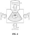
- FIG. 6 is a schematic diagram for illustrating a process of generating a three-dimensional image picture by an ultrasound medical apparatus according to some embodiments.
- the ultrasound medical apparatus 100 transmits the first imaging ultrasound or the second imaging ultrasound to the target object, receives the first echo signal or the second echo signal reflected from the target object, generates the first reception signal or the second reception signal based on the first echo signal or the second echo signal, generates the first image picture or the second image picture based on the first reception signal or the second reception signal, and then outputs the first image picture or the second image picture to the display unit 140.
- the first image picture or the second image picture generated by the ultrasound medical apparatus 100 is a three-dimensional image; however, the present disclosure is not limited to this scheme.
- the ultrasound medical apparatus 100 receives the first echo signal corresponding to the first imaging ultrasound transmitted by the 2D transducer array, and generates the first image picture as a three-dimensional image based on the first echo signal, or receives the second echo signal corresponding to the second imaging ultrasound, and generates the second image picture as a three-dimensional image based on the second echo signal.
- the imaging transducer 110 of the ultrasound medical apparatus 100 includes a 1D, 1.25D, 1.5D and 1.75D transducer arrays
- the ultrasound medical apparatus 100 can generate a three-dimensional image in a manner shown in FIG. 3 .
- the ultrasound medical apparatus 100 transmits the first imaging ultrasounds to the target object while rotating the 1D, 1.25D, 1.5D and 1.75D transducer arrays by a predetermined angle (0° to 360°), receives the respective first echo signals reflected from the target object, and then generates the first image picture as a three-dimensional image based on the respective first echo signals, or transmits the second imaging ultrasounds to the target object, receives the respective second echo signals reflected from the target object, and then generates the second image picture as a three-dimensional image based on the second echo signal.
- the first imaging ultrasounds or the second ultrasounds are transmitted to the target object by using the imaging transducer 110 in a horizontal direction and a vertical direction with respect to the treatment transducer 112, and based on the first echo signals or the second echo signals reflected and received from the target object, the first image picture or the second image picture can be generated as a three-dimensional image.
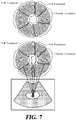
- FIG. 7 is a schematic diagram of a treatment transducer including a plurality of groups according to some embodiments.
- the high-intensity transducer array of the treatment transducer 112 can be divided into a plurality (at least two or more) groups.
- the ultrasound medical apparatus 100 utilizes the treatment transducer 112 to transmit the high-intensity ultrasound having the intensity lower than the predetermined output value to the subject to be treated (target object).
- a plurality of grouped divisions of the high-intensity transducer array can also be used successfully to transmit the high-intensity ultrasound having the intensity lower than the predetermined output value to the subject to be treated (target object) and then receive the second echo signals before harming the subject to be treated (human tissue).
- the ultrasound medical apparatus 100 compensates for the phase by applying an optimization algorithm to the plurality of groups.
- the applicable phase is one that occurs when the reflected signal is maximized out of the focal point information, and the applicable optimum solution may be one among a set of various solutions for use as the optimization algorithm.
- the treatment transducer 112 is described below with reference to FIG. 7 .
- the transducers are arranged to form a specific group depending on the first high-intensity ultrasound having an intensity lower than a predetermined output value, the second high-intensity ultrasound having an intensity lower than the predetermined output value, and the N-th high-intensity ultrasound having an intensity lower than the predetermined output value to be transmitted to the focal point corresponding to the focal-point information or arranged in a random manner.
- the treatment transducer 112 transmits a combination of a plurality of high-intensity ultrasounds with a ratio loaded to the specific region of the target object, or transmits the high-intensity ultrasound having the intensity lower than the predetermined output value by using each of the groups.
- the treatment transducer 112 transmits the high-intensity ultrasound to a specific site (the focal point corresponding to the focal-point information) adjusted via the user input unit 150.
- a user i.e., an operator
- the user inputs a location value corresponding to the specific region to the user input unit 150 or determines the corresponding location by adjusting a direction key such as a joystick.
- the high-intensity ultrasound having the intensity lower than the predetermined output value can be transmitted to the specific region of the target object, such as cancer tissue, tumor tissue, or lesion tissue.
- the treatment transducer 112 can be manufactured in a circular shape with the imaging transducer 110 arranged at the center; however, the present invention is not limited to this scheme.
- the treatment transducer 112 transmits a combination of a plurality of high-intensity ultrasounds with a ratio loaded to the specific site of the target object under a control of the control unit.
- the treatment transducer 112 includes a first transducer that transmits a first high-intensity ultrasound having an intensity lower than a predetermined output value based on a fundamental frequency to the specific site of the target object, a second transducer that transmits a second high-intensity ultrasound having an intensity lower than a predetermined output value based on a second frequency to the specific site of the target object, and an N-th transducer that transmits an N-th high-intensity ultrasound having an intensity lower than a predetermined output value based on an N-th frequency to the specific site of the target object.
- the first transducer, the second transducer, and the N-th transducer are physically similar transducers; however, in some embodiments, they are distinguishably described as the first transducer, the second transducer, and the N-th transducer for the purpose of illustration.
- the treatment transducer 112 includes a first group including the first transducers, a second group including the second transducers, and an N-th group including the N-th transducers. Further, in some embodiments, as shown in FIG. 7 , the treatment transducer 112 includes the first transducers, the second transducers, and the N-th transducers arranged in a random manner.
Landscapes
- Health & Medical Sciences (AREA)
- Life Sciences & Earth Sciences (AREA)
- Engineering & Computer Science (AREA)
- Biomedical Technology (AREA)
- Nuclear Medicine, Radiotherapy & Molecular Imaging (AREA)
- Radiology & Medical Imaging (AREA)
- Animal Behavior & Ethology (AREA)
- General Health & Medical Sciences (AREA)
- Public Health (AREA)
- Veterinary Medicine (AREA)
- Physics & Mathematics (AREA)
- Pathology (AREA)
- Biophysics (AREA)
- Heart & Thoracic Surgery (AREA)
- Medical Informatics (AREA)
- Molecular Biology (AREA)
- Surgery (AREA)
- Computer Networks & Wireless Communication (AREA)
- General Physics & Mathematics (AREA)
- Radar, Positioning & Navigation (AREA)
- Remote Sensing (AREA)
- Computer Vision & Pattern Recognition (AREA)
- Surgical Instruments (AREA)
- Physiology (AREA)
Description
- The present disclosure relates to an apparatus for compensating a focal point, and more particularly, to a method and an ultrasound medical apparatus for focusing a high-intensity ultrasound having an intensity lower than a predetermined output value on a target object (an affected area of a patient), and compensating for a distance of the focal point by a difference as determined to be present between the focal point on the target object and the actual ultrasound focusing location.
- The statements in this section merely provide background information related to the present disclosure and do not necessarily constitute prior art.
- A high-intensity focused ultrasound (HIFU) is generally used for treating (processing) a biological tissue such as cancer, tumor, and lesion. The treatment method using a high-intensity ultrasound necrotizes a biological tissue by using a heat generated by transmitting the high-intensity ultrasound to a single spot in a focused manner. In this case, the high-intensity ultrasound needs to be controlled not to damage a healthy biological tissue, and using such a high-intensity focused ultrasound obviates an incision process from a surgical operation.
- In an exemplary treatment method using the high-intensity ultrasound, an ultrasound for acquiring an image is transmitted to a biological tissue to be treated, an image is acquired by using an echo signal which is a reflected signal of the ultrasound, and then a high-intensity ultrasound is transmitted to the corresponding biological tissue. In this case, a possible difference between the focal point to be treated by the ultrasound medical apparatus and the actual location where the high-intensity ultrasound is focused causes damage to a biological tissue out of the focal point.
-
WO 2004/075987 A1 discloses a high intensity focused ultrasound (HIFU) for medically treating tumors that is automatically administered under robotic control in dosage intervals that alternate with ultrasonic imaging intervals. - The present disclosure has been made in an effort to effectively resolving at least a part of the above-mentioned problems, and it is an object of some embodiments of the present disclosure to provide an ultrasound medical apparatus for focusing a high-intensity ultrasound having an intensity lower than a predetermined output value on a target object or an affected area of a patient, and when it is determined that there is a difference between the focal point on the target object and the actual ultrasound focusing location, compensating for a distance of the focal point by the difference.
- The invention is defined by the appended independent claim. Preferred embodiments of the invention are illustrated in the dependent claims. According to some embodiments of the present disclosure, an ultrasound medical apparatus is provided, which includes an imaging transducer configured to transmit a first imaging ultrasound to a target object, to receive a first echo signal reflected from the target object, and to generate a first reception signal based on the first echo signal, a signal processing unit configured to generate a first image picture based on the first reception signal and to output the first image picture to a display unit, a user input unit configured to receive an input of focal-point information on the first image picture, a treatment transducer configured to transmit a high-intensity ultrasound having an intensity lower than a predetermined output value to a focal point corresponding to the focal-point information, a focusing-location extracting unit configured to extract actual focal-point information by using a change amount of a second image picture that is generated based on a second imaging ultrasound transmitted at a time when the high-intensity ultrasound reaches the focal point, and a compensating unit configured to generate a compensation value based on the focal-point information and the actual focal-point information and to apply the compensation value to the focal-point information.
- According to another embodiment of the present disclosure, a method, not according to the present invention, for compensating for a focal point in an ultrasound medical apparatus is provided, which includes:
- a first reception signal generating step including transmitting a first imaging ultrasound to a target object, receiving a first echo signal reflected from the target object, and generating a first reception signal based on the first echo signal,
- a first image processing step including generating a first image picture based on the first reception signal, and outputting the first image picture to a display unit,
- a focal point inputting step including receiving an input of focal-point information on the first image picture,
- a high-intensity ultrasound transmitting step including transmitting a high-intensity ultrasound having an intensity lower than a predetermined output value to a focal point corresponding to the focal-point information,
- an actual focal-point extracting step including extracting actual focal-point information by using a change amount of a second image picture that is generated based on a second imaging ultrasound transmitted at a time when the high-intensity ultrasound reaches the focal point, and
- a compensating step including generating a compensation value based on the focal-point information and the actual focal-point information, and applying the compensation value to the focal-point information.
- According to some embodiments of the present disclosure as described above, a pre-targeting can be achieved by focusing a high-intensity ultrasound having an intensity lower than a predetermined output value on a target object or an affected area of a patient and using a reflected signal of the ultrasound, and when an error occurs between the focal point on the target object and the actual ultrasound focusing location, a distance of the focal point can be compensated by as much as the difference. According to some embodiments, a pre-targeting is performed to avail of the correct focus by transmitting an undamaging level of high-intensity ultrasound to a human tissue at the focal point, and a possible mismatch between the focal point on the target object and the actual ultrasound focusing location can be compensated by using an electronic compensation value without a physical movement.
- Further, according to some embodiments, off-focusing issues are addressed when the treatment transducer transmits the high-intensity ultrasound for treatment to the set focal point and if there is a mismatch between the focal-point information and the actual focusing location information risking damage to a biological tissue (target object) deviated from the treatment focal-point information, by compensating the difference between the focal-point information and the actual focusing location information, thereby treating the site to be treated in a precise manner.
-
-
FIG. 1 is a block diagram of an ultrasound medical apparatus according to some embodiments. -
FIG. 2 is a schematic diagram of a high-intensity ultrasound having an intensity lower than a predetermined output value according to some embodiments. -
FIG. 3 is a schematic diagram for illustrating focal-point information on an image picture according to some embodiments. -
FIG. 4 is a flowchart of a method for compensating for a focal point. -
FIGs. 5A and 5B are schematic diagrams for illustrating a difference between the focal-point information and the actual focusing location information according to some embodiments. -
FIG. 6 is a schematic diagram for illustrating a process of generating a three-dimensional image picture by an ultrasound medical apparatus according to some embodiments. -
FIG. 7 is a schematic diagram of a treatment transducer including a plurality of groups according to some embodiments. - Hereinafter, at least one embodiment of the present disclosure will be described in detail with reference to the accompanying drawings.
- A first imaging ultrasound described in some embodiments refers to an ultrasound that is transmitted to a target object to obtain an image by using an
imaging transducer 110. On the other hand, a second imaging ultrasound described in some embodiments refers to an ultrasound that is transmitted to the target object by theimaging transducer 110 at a time when a high-intensity ultrasound is transmitted by atreatment transducer 112 and reaches a focal point. When a high-intensity ultrasound having an intensity lower than a predetermined output value is transmitted by thetreatment transducer 112 based on a sort of synchronization between theimaging transducer 110 and thetreatment transducer 112, theimaging transducer 110 can determine the time when the high-intensity ultrasound reaches the focal point and transmit the second imaging ultrasound to the target object according to the arrival time of the high-intensity ultrasound. Such a synchronization can be set based on a distance information between theimaging transducer 110 and the focal point, distance information between thetreatment transducer 112 and the focal point, and traveling speed information of the first imaging ultrasound, the second imaging ultrasound, and the high-intensity ultrasound traveling in the medium of the target object. - A diagnostic image described in some embodiments includes a B-mode image, a C-mode image, and the like. The B-mode image is a grayscale image in an image mode for displaying a motion of a target object, and the C-mode image is an image in a color flow image mode. A BC-mode image is an image in an image mode for displaying a blood flow or a motion of the target object by using a Doppler effect, which simultaneously provides the B-mode image and the C-mode image to provide anatomic information together with the blood flow and the motion of the target object. The B-mode is a grayscale image mode for displaying the motion of the target object, and the C-mode is a color flow image mode for displaying the blood flow or the motion of the target object. An ultrasound
medical apparatus 100 according to some embodiments is capable of simultaneously providing the B-mode image and the C-mode image that is a color flow image; however, for the purpose of illustration, descriptions are given with an assumption that a diagnostic image is a B-mode image that is provided by the ultrasoundmedical apparatus 100 in the present disclosure. -
FIG. 1 is a block diagram of an ultrasound medical apparatus according to some embodiments. - An ultrasound
medical apparatus 100 includes animaging transducer 110, atreatment transducer 112, an analog-to-digital converter 120, animage processing unit 130, adisplay unit 140, auser input unit 150, and astorage unit 160. To illustrate an exemplary technical idea of some embodiments, the ultrasoundmedical apparatus 100 specifically includes theimaging transducer 110,treatment transducer 112, analog-to-digital converter 120,image processing unit 130,display unit 140,user input unit 150 andstorage unit 160 in some embodiments, although one of ordinary skill in the pertinent art would appreciate that various modifications, additions and substitutions are possible in the constituent elements of the ultrasoundmedical apparatus 100 without departing from the scope of the embodiments. - The
imaging transducer 110 includes an imaging transducer array, transmits a first imaging ultrasound and a second imaging ultrasound to a target object, and receives a first echo signal and a second echo signal reflected from the target object. This transducer converts an electrical analog signal into an ultrasound, transmits the ultrasound to the target object, converts the echo signal reflected from the target object into an electrical analog signal, and includes a plurality of transducer elements coupled to each other. Thisimaging transducer 110 includes one-dimensional (1D), 1.25D, 1.5D, 1.75D, or 2D transducer array. For example, when theimaging transducer 110 includes 1D, 1.25D, 1.5D, or 1.75D transducer array, the 1D, 1.25D, 1.5D, or 1.75D transducer array transmits the first imaging ultrasound or the second imaging ultrasound while rotating in a predetermined angle (0° to 360°), and forms a first reception signal or a second reception signal by receiving the first echo signal or the second echo signal from the target object. On the other hand, when theimaging transducer 110 includes 2D transducer array, theimaging transducer 110 transmits the first imaging ultrasound or the second imaging ultrasound via the 2D transducer array without a rotation, and forms the first reception signal or the second reception signal by receiving the first echo signal or the second echo signal from the target object. Theimaging transducer 110 transmits an ultrasound beam, which is focused by appropriately delaying an input time of a pulse inputted to each transducer, to the target object along a transmission scanline. On the other hand, the first echo signal or the second echo signal reflected from the target object is inputted to each transducer with a different reception time, and each transducer outputs the first echo signal or the second echo signal to abeamformer 132. - The
imaging transducer 110 transmits the first imaging ultrasound to the target object, receives the first echo signal reflected from the target object, and forms the first reception signal based on the first echo signal. In some embodiments, theimaging transducer 110 further transmits the second imaging ultrasound to the target object at a time when the high-intensity ultrasound reaches the focal point, receives the second echo signal reflected in response to the second imaging ultrasound, and forms the second reception signal based on the second echo signal. When a high-intensity ultrasound having an intensity lower than a predetermined output value reaches the focal point, although a human tissue corresponding to the focal point is not damaged, the corresponding human tissue is depressed or a density of the human tissue is changed by the high-intensity ultrasound having the intensity lower than the predetermined output value. The second imaging ultrasound is transmitted to the target object at the time when the high-intensity ultrasound reaches the focal point, and then reflected second echo signal is received, which can detect the spot where the human tissue is depressed or the density of the human tissue is changed by the high-intensity ultrasound having the intensity lower than the predetermined output value. In other words, when the focal point is irradiated with an acoustic pressure having a high amplitude (high-intensity ultrasound), the medium is instantly depressed to cause a change of density and wave velocity, and the ultrasound is reflected due to a difference in the acoustic impedance. In order to determine the time when the high-intensity ultrasound reaches the focal point by theimaging transducer 110, when the high-intensity ultrasound having the intensity lower than the predetermined output value is transmitted by thetreatment transducer 112 under a sort of synchronization between theimaging transducer 110 and thetreatment transducer 112, theimaging transducer 110 transmits the second imaging ultrasound to the target object according to the arrival time of the high-intensity ultrasound. Such a synchronization can be set based on the distance information between theimaging transducer 110 and the focal point, the distance information between thetreatment transducer 112 and the focal point, and the traveling speed information of the first imaging ultrasound, the second imaging ultrasound, and the high-intensity ultrasound traveling in the medium of the target object. - The
treatment transducer 112 includes a high-intensity transducer array, and transmits a high-intensity ultrasound having an intensity lower than a predetermined output value or a high-intensity ultrasound for treatment (corresponding to the predetermined output value) to a specific region of the target object. Thetreatment transducer 112 transmits the high-intensity ultrasound having the intensity lower than the predetermined output value to a focal point corresponding to focal-point information. Thetreatment transducer 112 transmits a high-intensity ultrasound having a duty ratio lower than a predetermined ratio and a pulse amplitude exceeding a predetermined threshold value to the target object. For example, thetreatment transducer 112 transmits the high-intensity ultrasound for treatment and the high-intensity ultrasound for pre-targeting. That is, thetreatment transducer 112 transmits the high-intensity ultrasound for pre-targeting with a low intensity (with the duty ratio lower than the predetermined ratio, e.g., equal to or smaller than 5%) not to damage the human tissue (target object) or transmits the high-intensity ultrasound with a high intensity (with the duty ratio of the predetermined ratio of, e.g., 100%). At this time, thetreatment transducer 112 repeatedly transmits the high-intensity ultrasound having the intensity lower than the predetermined output value for predetermined times. For example, thetreatment transducer 112 makes a test pre-targeting by performing about two repeat transmissions of the high-intensity ultrasound having the intensity lower than the predetermined output value to the target object. In some embodiments, the two repeat transmissions are good for the high-intensity ultrasound having the intensity lower than the predetermined output value; however, the present disclosure is not limited thereto. - An exemplary operation of the
treatment transducer 112 is described below. Thetreatment transducer 112 transmits the high-intensity ultrasound (one having the intensity lower than the predetermined output value or having the intensity corresponding to the predetermined output value) to a specific site determined via theuser input unit 150. In this case, the user first transmits the first imaging ultrasound to the target object via theimaging transducer 110, receives the first echo signal reflected from the target object, and determines the specific site (focal point corresponding to the focal-point information) of the target object through a first image picture generated based on the first reception signal obtained upon receiving the first echo signal. In order for the user to determine the specific site (focal point corresponding to the focal-point information), the user inputs a location value corresponding to the specific site via theuser input unit 150 or determines the corresponding site by using a direction key such as a joystick. With this operation, the high-intensity ultrasound can be transmitted to the specific site of the target object, such as cancer tissue, tumor tissue, lesion tissue, or the like. In some embodiments, thetreatment transducer 112 is manufactured in a circular shape with theimaging transducer 110 arranged at the center; however, the present disclosure is not limited to this scheme. - In some embodiments, the
treatment transducer 112 is divided into a plurality of groups. Thetreatment transducer 112 includes a high-intensity transducer array which is divided into a first transducer that transmits a first high-intensity ultrasound having an intensity lower than a predetermined output value based on a fundamental frequency to the specific site of the target object, a second transducer that transmits a second high-intensity ultrasound having an intensity lower than a predetermined output value based on a second frequency to the specific site of the target object, and an N-th transducer that transmits an N-th high-intensity ultrasound having an intensity lower than a predetermined output value based on an N-th frequency to the specific site of the target object. Thetreatment transducer 112 includes a first group including at least one first transducer, a second group including at least one second transducer, and an N-th group including at least one N-th transducer. Further, in some embodiments, thetreatment transducer 112 includes the first transducer, the second transducer, and the N-th transducer arranged in a random manner. In this case, thetreatment transducer 112 transmits a combination of a plurality of high-intensity ultrasounds with a ratio loaded to the specific region of the target object, or transmits the high-intensity ultrasound having the intensity lower than the predetermined output value by using each of the groups. - The analog-to-
digital converter 120 converts the electrical analog signal obtained by the transducer of theimaging transducer 110 or thetreatment transducer 112 into an electrical digital signal.FIG. 1 shows that the analog-to-digital converter 120 is arranged between the transducer (theimaging transducer 110 or the treatment transducer 112) and thebeamformer 132, although the present invention is not limited to this scheme. One of ordinary skill in the pertinent art would appreciate that various modifications are possible in the arrangement of the analog-to-digital converter 120 between other modules in the ultrasoundmedical apparatus 100 without departing from the idea and scope of the embodiments. - The
image processing unit 130 generates a first image picture by using the first reception signal generated based on the first echo signal corresponding to the first imaging ultrasound from theimaging transducer 110. Further, theimage processing unit 130 generates a second image picture by using the second reception signal generated based on the second echo signal corresponding to the second imaging ultrasound from theimaging transducer 110. - Further, the
image processing unit 130 is configured to set a region of interest (ROI) on the first image picture by an operation or an instruction from theuser input unit 150. Theimage processing unit 130 receives the first echo signal from an image transducer that is rotated by a predetermined angle (0° to 360°) or from theimaging transducer 110 that includes a two-dimensional (2D) transducer array, and forms the first image picture as a three-dimensional image based on the received first echo signal. Further, theimage processing unit 130 receives the second echo signal from the imaging transducer that is rotated by a predetermined angle (0° to 360°) or from theimaging transducer 110 that includes a 2D transducer array, and forms the second image picture as a three-dimensional image based on the received second echo signal. - The
image processing unit 130 includes abeamformer 132, asignal processing unit 134, ascan converter 136, a focusing-location extracting unit 138, and a compensatingunit 139. Thebeamformer 132 focuses the first echo signal and the second echo signal received by each transducer of theimaging transducer 110, and generates frame data as raw data. Thebeamformer 132 generates a receive focusing signal based on the electrical digital signal obtained by the analog-to-digital converter 120. Further, thebeamformer 132 is configured to generate the receive focusing signal by adding an appropriate delay to each electrical digital signal and then summing the electrical digital signals, considering a time required to reach each transducer of theimaging transducer 110 and thetreatment transducer 112 from the target object. Thebeamformer 132 focuses the ultrasound on a focal point (specific site) corresponding to the focal-point information by adjusting driving timing of each transducer in theimaging transducer 110 and thetreatment transducer 112 when theimaging transducer 110 transmits the first imaging ultrasound or the second imaging ultrasound or thetreatment transducer 112 transmits the high-intensity ultrasound. Further, thebeamformer 132 focuses the first echo signal and the second echo signal by adding a time delay to each of the first imaging ultrasound signal and the second imaging ultrasound signal of theimaging transducer 110, considering the difference in time required for the first echo signal and the second echo signal reflected at the target subject to reach each transducer of theimaging transducer 110. Thebeamformer 132 in its implementation includes an imaging beamformer corresponding to theimaging transducer 110 and a treatment beamformer corresponding to thetreatment transducer 112, and each of the imaging beamformer and the treatment beamformer includes a transmit beamformer and a receive beamformer. - The
signal processing unit 134 generates the first image picture or the second image picture by performing a digital signal processing on the frame data signal generated by thebeamformer 132. That is, thesignal processing unit 134 generates the first image signal based on the first reception signal received from theimaging transducer 110, and outputs the first image picture to thedisplay unit 140. Further, thesignal processing unit 134 generates the second image signal based on the second reception signal received from theimaging transducer 110, and outputs the second image picture to thedisplay unit 140. Thescan converter 136 converts a data format of the first image picture or the second image picture into a data format that can be used in thedisplay unit 140 of a predetermined scanline display format. That is, thescan converter 136 converts the first image picture signal or the second image picture signal into a signal of a data format that can be actually displayed on thedisplay unit 140. - The focusing-
location extracting unit 138 according to some embodiments extracts actual focusing-location information by using a change amount of the second image picture generated based on the second imaging ultrasound transmitted at the time when the high-intensity ultrasound reaches the focal point. That is, theimaging transducer 110 transmits the second imaging ultrasound at the time when the high-intensity ultrasound having the intensity lower than the predetermined output value transmitted by thetreatment transducer 112 reaches the focal point, receives the second echo signal reflected in response to the second imaging ultrasound, and generates the second reception signal based on the second echo signal. Thereafter, thesignal processing unit 134 generates the second image picture based on the second reception signal, and at this time, the focusing-location extracting unit 138 extracts the actual focusing-location information by using the change amount of the second image picture. In order to detect the change amount of the second image picture, the focusing-location extracting unit 138 extracts a location having the largest change amount of gray-scale of the second image picture, and determines the location having the largest change amount as the actual focusing-location information. The gray-scale is an index of brightness difference, which is a gradual step ranging from white to black. In a digital image, each pixel value indicates a single sample image, and the digital image delivers luminous intensity information only. When the second image picture is a two-dimensional image, the focusing-location extracting unit 138 determines two-dimensional coordinates as the actual focusing-location information (x1, z1), and when the second image picture is a three-dimensional image, it determines three-dimensional coordinates as the actual focusing-location information (x1, y1, z1). - The compensating
unit 139 according to some embodiments extracts a compensation value based on the focal-point information and the actual focusing-location information, and then applies the compensation value to the focal-point information. When the second image picture is a two-dimensional image, the compensatingunit 139 generates the compensation value (Δx, Δz) based on a difference (x - x1, z - z1) between the focal-point information (x, z) on two-dimensional coordinates and the actual focal-point information (x1, z1) on the two-dimensional coordinates, and when the second image picture is a three-dimensional image, it generates the compensation value (Δx, Δy, Δz) based on a difference (x - x1, y - y1, z - z1) between the focal-point information (x, y, z) on three-dimensional coordinates and the actual focal-point information (x1, y1, z1) on the three-dimensional coordinates. Further, when the second image picture is a two-dimensional image, the compensatingunit 139 generates compensation location information (x + Δx, z + Δz) by applying the compensation value (Δx, Δz) to the focal-point information (x, z) on the two-dimensional coordinates, and when the second image picture is a three-dimensional image, it generates compensation location information (x + Δx, y + Δy, z + Δz) by applying the compensation value (Δx, Δy, Δz) to the focal-point information (x, y, z) on the three-dimensional coordinates. That is, when thetreatment transducer 112 transmits the high-intensity ultrasound for treatment with the focal-point information set by theuser input unit 150, a possible difference between the focal-point information (x, y, z) and the actual focusing-location information (x1, y1, z1) risks damage to a biological tissue (target object) deviated from the focal-point information to be treated may be damaged. Therefore, the compensatingunit 139 according to some embodiments detects the difference between the focal-point information (x, y, z) and the actual focusing-location information (x1, y1, z1), and compensates for the distance (Δx, Δy, Δz) by the difference, thus accurately treating the site at issue. - The
display unit 140 outputs the first image picture or the second image picture received from theimage processing unit 130 as a B-mode image or a C-mode image. Theuser input unit 150 receives an instruction by an operation or an input of a user. The user instruction includes a control instruction to control the ultrasoundmedical apparatus 100 and the like. Further, theuser input unit 150 receives an input of the focal-point information on the first image picture. That is, when the first image picture is a two dimensional image, theuser input unit 150 receives an input of the focal-point information of two-dimensional coordinates (x, z), and when the first image picture is a three-dimensional image, it receives an input of the focal-point information of three-dimensional coordinates (x, y, z). Moreover, theuser input unit 150 is configured to set an ROI on the first image picture by an operation or an instruction from the user. Thestorage unit 160 is for storing various data for driving the ultrasoundmedical apparatus 100, which stores at least one of the first image picture or the second image picture. Further, thestorage unit 160 stores the first reception signal or the second reception signal generated by using theimaging transducer 110. -
FIG. 2 is a schematic diagram of a high-intensity ultrasound having an intensity lower than a predetermined output value according to some embodiments. - As shown in
FIG. 2 , the high-intensity ultrasound having the intensity lower than the predetermined output value according to some embodiments has a duty ratio lower than a predetermined ratio and a pulse amplitude exceeding a predetermined threshold value. That is, thetreatment transducer 112 is configured to transmit a high-intensity ultrasound for treatment and another high-intensity ultrasound for pre-targeting. Thetreatment transducer 112 transmits the high-intensity ultrasound for pre-targeting with a low intensity (with the duty ratio lower than the predetermined ratio, e.g., equal to or smaller than 5%) not to damage the human tissue (target object). On the other hand, thetreatment transducer 112 transmits the high-intensity ultrasound with a high intensity (with the duty ratio of the predetermined ratio of, e.g., 100%) to treat the human tissue. That is, in the example shown inFIG. 2 , thetreatment transducer 112 transmits the high-intensity ultrasound for pre-targeting with a low intensity (with the duty ratio lower than the predetermined ratio, e.g., equal to or smaller than 5%) not to damage the human tissue (target object). At this time, thetreatment transducer 112 transmits the high-intensity ultrasound with a low intensity (with the duty ratio lower than the predetermined ratio, e.g., equal to or smaller than 5%) not to damage the human tissue (target object) in a repeated manner for a predetermined number of times to a specific site of the target object (focal point corresponding to the focal-point information). That is, thetreatment transducer 112 performs a number of (about two) repeat transmissions of the high-intensity ultrasound having the intensity lower than the predetermined output value to the target object, thus performing the pre-targeting. - As shown in
FIG. 2 , in some embodiments, the high-intensity ultrasound that is set as low as not to damage the human tissue (target object) (to have a duty ratio lower than a predetermined ratio (e.g., equal to or smaller than about 5%) has a pulse amplitude of equal to or larger than about 3 MPa; however, the present invention is not limited to this scheme. The unit MPa is a unit of acoustic pressure, and the acoustic pressure can be represented as an acoustic Intensity (unit: W/cm2). That is, the acoustic pressure of 3 MPa can be converted into the acoustic intensity of 580 W/cm2. When treating the human tissue (target object), energy is equal to power x time, and hence in order to reduce the damage, the time should be decreased. To this end, the duty ratio is set to be small (e.g., equal to or smaller than about 5%). -
FIG. 3 is a schematic diagram for illustrating focal-point information on an image picture according to some embodiments. - In some embodiments, the ultrasound
medical apparatus 100 transmits the first imaging ultrasound or the second imaging ultrasound to the target object, receives the first echo signal or the second echo signal reflected from the target object, generates the first reception signal or the second reception signal based on the first echo signal or the second echo signal, generates the first image picture or the second image picture based on the first reception signal or the second reception signal, and then outputs the first image picture or the second image picture to thedisplay unit 140. In some embodiments, the first image picture or the second image picture generated by the ultrasoundmedical apparatus 100 is a three-dimensional image; however, the present invention is not limited to this scheme. When theimaging transducer 110 in the ultrasoundmedical apparatus 100 includes a 2D transducer array, the ultrasoundmedical apparatus 100 generates the first image picture as a three-dimensional image based on the first echo signal received corresponding to the first imaging ultrasound transmitted by the 2D transducer array. On the other hand, when theimaging transducer 110 in the ultrasoundmedical apparatus 100 includes a 2D transducer array, the ultrasoundmedical apparatus 100 generates the second image picture as a three-dimensional image based on the second echo signal received corresponding to the second imaging ultrasound transmitted by the 2D transducer array. - However, when the
imaging transducer 110 in the ultrasoundmedical apparatus 100 includes a 1D, 1.25D, 1.5D and 1.75D transducer arrays, the ultrasoundmedical apparatus 100 transmits the first imaging ultrasound or the second imaging ultrasound while rotating the 1D, 1.25D, 1.5D and 1.75D transducer arrays by a predetermined angle (0° to 360°), receives the first echo signal or the second echo signal reflected from the target object, and then generates the first image picture or the second image picture based on the first echo signal or the second echo signal. As described above, when the first image picture or the second image picture is a three-dimensional image, as shown inFIG. 3 , the coordinates can be represented as (x, y, z). When theimaging transducer 110 includes a 1D, 1.25D, 1.5D and 1.75D transducer arrays, the first image picture or the second image can be generated as a two-dimensional image, and in this case, the coordinates can be represented as (x, z). -
FIG. 4 is a flowchart of a method of compensating for a focal point. - The
imaging transducer 110 of the ultrasoundmedical apparatus 100 transmits the first imaging ultrasound to the target object, receives the first echo signal reflected from the target object, and generates the first reception signal based on the first echo signal (step S410). Thesignal processing unit 134 of the ultrasoundmedical apparatus 100 generates the first image picture based on the first reception signal, and outputs the first image picture to the display unit 140 (step S420). - The
user input unit 150 of the ultrasoundmedical apparatus 100 receives an input of the focal-point information on the first image picture (step S430). At step S430, when the first image picture is a two-dimensional image, theuser input unit 150 receives the focal-point information of two-dimensional coordinates (x, z), and when the first image picture is a three-dimensional image, it receives the focal-point information of three-dimensional coordinates (x, y, z). - The
treatment transducer 112 of the ultrasoundmedical apparatus 100 transmits the high-intensity ultrasound having the intensity lower than the predetermined output value to the focal point corresponding to the focal-point information (step S440). The high-intensity ultrasound having the predetermined output value has a duty ratio lower than a predetermined ratio and a pulse amplitude exceeding a predetermined threshold value. That is, the high-intensity ultrasound having the intensity lower than the predetermined output value means a high-intensity ultrasound having an intensity as low as not to damage the human tissue (target object) or having a duty ratio lower than a predetermined ratio, e.g., equal to or smaller about 5%. - The
imaging transducer 110 of the ultrasoundmedical apparatus 100 transmits the second imaging ultrasound to the target object at the time when the high-intensity ultrasound from thetreatment transducer 112 reaches the focal point, receives the second echo signal reflected in response to the second imaging ultrasound, and generates the second reception signal based on the second echo signal (step S450). Thesignal processing unit 134 of the ultrasoundmedical apparatus 100 generates the second image picture based on the second reception signal (step S460). - The focusing-
location extracting unit 138 of the ultrasoundmedical apparatus 100 extracts the actual focusing-location information by using the change amount of the second image picture (step S470). At step S470, the focusing-location extracting unit 138 of the ultrasoundmedical apparatus 100 extracts a location having the largest change amount of the gray-scale of the second image picture, and determines the location having the largest change amount as the actual focusing-location information. At this time, when the second image picture is a two-dimensional image, the focusing-location extracting unit 138 of the ultrasoundmedical apparatus 100 determines the two-dimensional coordinates as the actual focusing-location information (x1, z1), and when the second image picture is a three-dimensional image, it determines the three-dimensional coordinates as the actual focusing-location information (x1, y1, z1). - The compensating
unit 139 of the ultrasoundmedical apparatus 100 extracts a compensation value based on the focal-point information and the actual focusing-location information, and then applies the compensation value to the focal-point information (step S480). At step S480, when the second image picture is a two-dimensional image, the compensatingunit 139 of the ultrasoundmedical apparatus 100 generates the compensation value (Δx, Δz) based on a difference (x - x1, z - z1) between the focal-point information (x, z) on two-dimensional coordinates and the actual focal-point information (x1, z1) on the two-dimensional coordinates, and when the second image picture is a three-dimensional image, it generates the compensation value (Δx, Δy, Δz) based on a difference (x - x1, y - y1, z - z1) between the focal-point information (x, y, z) on three-dimensional coordinates and the actual focal-point information (x1, y1, z1) on the three-dimensional coordinates. Thereafter, when the second image picture is a two-dimensional image, the compensatingunit 139 of the ultrasoundmedical apparatus 100 generates compensation location information (x + Δx, z + Δz) by applying the compensation value (Δx, Δz) to the focal-point information (x, z) on the two-dimensional coordinates, and when the second image picture is the three-dimensional image, it generates compensation location information (x + Δx, y + Δy, z + Δz) by applying the compensation value (Δx, Δy, Δz) to the focal-point information (x, y, z) on the three-dimensional coordinates. - Steps S410 to S480 are described to be sequentially performed in
FIG. 4 as a mere example for describing the technical idea of some embodiments, although one of ordinary skill in the pertinent art would appreciate that various modifications, additions and substitutions are possible by performing the sequences shown inFIG. 4 in a different order or at least one of Steps S410 to S480 in parallel without departing from the idea and scope of the embodiments, and hence the example shown inFIG. 4 is not limited to the chronological order. - The method of compensating the focal point shown in
FIG. 4 can be implemented as a computer program, and can be recorded on a computer-readable medium. The computer-readable recording medium on which the method of compensating the focal point according to some embodiments is recordable includes any type of recording device on which data that can be read by a computer system are recordable. Examples of the computer-readable recording medium include a ROM, a RAM, a CD-ROM, a magnetic tape, a floppy disk, an optical data storage device, and the like, and also include one implemented in the form of carrier wave (e.g., transmission through the Internet). Further, the computer-readable recording medium can be distributed in computer systems connected via a network, and computer-readable codes can be stored and executed in a distributed mode. Moreover, functional programs, codes, and code segments for implementing some embodiments can be easily deduced by a programmer in technical fields to which some embodiments belong. -
FIGs. 5A and 5B are schematic diagrams for illustrating a difference between the focal-point information and the actual focusing location information according to some embodiments. - As shown in
FIGs. 5A and 5B , theuser input unit 150 of the ultrasoundmedical apparatus 100 receives an input of the focal-point information on the first image picture. When the first image picture is a three-dimensional image, theuser input unit 150 receives an input of the focal-point information of three-dimensional coordinates (x, y, z). As shown inFIGs. 5A and 5B , a location corresponding to the three-dimensional coordinates (x, y, z) is indicated by "+" on the first image picture. Thetreatment transducer 112 of the ultrasoundmedical apparatus 100 transmits the high-intensity ultrasound having the intensity lower than the predetermined output value to the focal point ("+" point shown inFIG. 5A ) corresponding to the focal-point information of the target object. Here, the ultrasoundmedical apparatus 100 transmits the high-intensity ultrasound having the intensity lower than the predetermined output value to a subject to be treated (target object) by using thetreatment transducer 112, to increase the reflected signal (second echo signal). That is, when the focal point is irradiated with an acoustic pressure with a large amplitude (high-intensity ultrasound), the medium is instantly depressed to cause changes of density and wave velocity, and hence the ultrasound is reflected due to a difference in the acoustic impedance. - Thereafter, the
imaging transducer 110 of the ultrasoundmedical apparatus 100 transmits the second imaging ultrasound to the target object at the time when the high-intensity ultrasound having the intensity lower than the predetermined output value reaches the focal point. Theimaging transducer 110 of the ultrasoundmedical apparatus 100 receives the second echo signal reflected in response to the second imaging ultrasound, and generates the second reception signal. Thesignal processing unit 134 of the ultrasoundmedical apparatus 100 generates the second image picture based on the second reception signal. The focusing-location extracting unit 138 of the ultrasoundmedical apparatus 100 extracts the actual focusing-location information (location indicated by "●" inFIG. 5A ) by using a change amount of the second image picture. - The focusing-
location extracting unit 138 of the ultrasoundmedical apparatus 100 extracts a location having the largest change amount of the gray-scale of the second image picture (location indicated by "●" inFIG. 5A ), and determines the location having the largest change amount as the actual focusing-location information (x1, y1, z1). The ultrasoundmedical apparatus 100 extracts the location having the largest change amount of the gray-scale (location indicated by "●" inFIGs. 5A and 5B ) in the ROI set on the second image picture by using the focusing-location extracting unit 138, to determine the actual focusing-location information (x1, y1, z1). - The compensating
unit 139 of the ultrasoundmedical apparatus 100 extracts the compensation value based on the focal-point information (location indicated by "+" inFIG. 5A ) and the actual focusing-location information (location indicated by "●" inFIG. 5A ), and then applies the compensation value to the focal-point information. Thereafter, as shown inFIG. 5B , when the second image picture is a three-dimensional image, the compensatingunit 139 of the ultrasoundmedical apparatus 100 generates the compensation value (Δx, Δy, Δz) based on a difference (x - x1, y - y1, z - z1) between the focal-point information (x, y, z) on three-dimensional coordinates and the actual focal-point information (x1, y1, z1) on the three-dimensional coordinates. As shown inFIG. 5B , when the second image picture is a three-dimensional image, the compensatingunit 139 of the ultrasoundmedical apparatus 100 generates compensation location information (x + Δx, y + Δy, z + Δz) by applying the compensation value (Δx, Δy, Δz) to the focal-point information (x, y, z) on the three-dimensional coordinates. -
FIG. 6 is a schematic diagram for illustrating a process of generating a three-dimensional image picture by an ultrasound medical apparatus according to some embodiments. - In some embodiments, the ultrasound
medical apparatus 100 transmits the first imaging ultrasound or the second imaging ultrasound to the target object, receives the first echo signal or the second echo signal reflected from the target object, generates the first reception signal or the second reception signal based on the first echo signal or the second echo signal, generates the first image picture or the second image picture based on the first reception signal or the second reception signal, and then outputs the first image picture or the second image picture to thedisplay unit 140. - In some embodiments, the first image picture or the second image picture generated by the ultrasound
medical apparatus 100 is a three-dimensional image; however, the present disclosure is not limited to this scheme. When theimaging transducer 110 of the ultrasoundmedical apparatus 100 includes a two-dimensional transducer array, the ultrasoundmedical apparatus 100 receives the first echo signal corresponding to the first imaging ultrasound transmitted by the 2D transducer array, and generates the first image picture as a three-dimensional image based on the first echo signal, or receives the second echo signal corresponding to the second imaging ultrasound, and generates the second image picture as a three-dimensional image based on the second echo signal. However, when theimaging transducer 110 of the ultrasoundmedical apparatus 100 includes a 1D, 1.25D, 1.5D and 1.75D transducer arrays, the ultrasoundmedical apparatus 100 can generate a three-dimensional image in a manner shown inFIG. 3 . - As shown in
FIG. 6 , the ultrasoundmedical apparatus 100 transmits the first imaging ultrasounds to the target object while rotating the 1D, 1.25D, 1.5D and 1.75D transducer arrays by a predetermined angle (0° to 360°), receives the respective first echo signals reflected from the target object, and then generates the first image picture as a three-dimensional image based on the respective first echo signals, or transmits the second imaging ultrasounds to the target object, receives the respective second echo signals reflected from the target object, and then generates the second image picture as a three-dimensional image based on the second echo signal. For example, the first imaging ultrasounds or the second ultrasounds are transmitted to the target object by using theimaging transducer 110 in a horizontal direction and a vertical direction with respect to thetreatment transducer 112, and based on the first echo signals or the second echo signals reflected and received from the target object, the first image picture or the second image picture can be generated as a three-dimensional image. -
FIG. 7 is a schematic diagram of a treatment transducer including a plurality of groups according to some embodiments. - To take account of the nonuniform internal tissues of a human body (target object), which cause variation of the phase of each acoustic wave reaching the set focal point through different human tissues, the high-intensity transducer array of the
treatment transducer 112 can be divided into a plurality (at least two or more) groups. The ultrasoundmedical apparatus 100 utilizes thetreatment transducer 112 to transmit the high-intensity ultrasound having the intensity lower than the predetermined output value to the subject to be treated (target object). - A plurality of grouped divisions of the high-intensity transducer array can also be used successfully to transmit the high-intensity ultrasound having the intensity lower than the predetermined output value to the subject to be treated (target object) and then receive the second echo signals before harming the subject to be treated (human tissue). The ultrasound
medical apparatus 100 compensates for the phase by applying an optimization algorithm to the plurality of groups. In this case, the applicable phase is one that occurs when the reflected signal is maximized out of the focal point information, and the applicable optimum solution may be one among a set of various solutions for use as the optimization algorithm. - The
treatment transducer 112 is described below with reference toFIG. 7 . As shown inFIG. 7 , in thetreatment transducer 112, the transducers are arranged to form a specific group depending on the first high-intensity ultrasound having an intensity lower than a predetermined output value, the second high-intensity ultrasound having an intensity lower than the predetermined output value, and the N-th high-intensity ultrasound having an intensity lower than the predetermined output value to be transmitted to the focal point corresponding to the focal-point information or arranged in a random manner. Thetreatment transducer 112 transmits a combination of a plurality of high-intensity ultrasounds with a ratio loaded to the specific region of the target object, or transmits the high-intensity ultrasound having the intensity lower than the predetermined output value by using each of the groups. - Further, the
treatment transducer 112 transmits the high-intensity ultrasound to a specific site (the focal point corresponding to the focal-point information) adjusted via theuser input unit 150. A user (i.e., an operator) first transmits the first imaging ultrasound to the target object by using theimaging transducer 110, and determines a specific region of the target object through the first image picture generated based on the first reception signal generated based on the first echo signal reflected from the target object. In order for the user (operator) to determine the specific region, the user inputs a location value corresponding to the specific region to theuser input unit 150 or determines the corresponding location by adjusting a direction key such as a joystick. With this operation, the high-intensity ultrasound having the intensity lower than the predetermined output value can be transmitted to the specific region of the target object, such as cancer tissue, tumor tissue, or lesion tissue. As shown inFIG. 7 , thetreatment transducer 112 can be manufactured in a circular shape with theimaging transducer 110 arranged at the center; however, the present invention is not limited to this scheme. - The
treatment transducer 112 transmits a combination of a plurality of high-intensity ultrasounds with a ratio loaded to the specific site of the target object under a control of the control unit. As shown inFIG. 7 , thetreatment transducer 112 includes a first transducer that transmits a first high-intensity ultrasound having an intensity lower than a predetermined output value based on a fundamental frequency to the specific site of the target object, a second transducer that transmits a second high-intensity ultrasound having an intensity lower than a predetermined output value based on a second frequency to the specific site of the target object, and an N-th transducer that transmits an N-th high-intensity ultrasound having an intensity lower than a predetermined output value based on an N-th frequency to the specific site of the target object. The first transducer, the second transducer, and the N-th transducer are physically similar transducers; however, in some embodiments, they are distinguishably described as the first transducer, the second transducer, and the N-th transducer for the purpose of illustration. - More specifically, as shown in
FIG. 7 , thetreatment transducer 112 includes a first group including the first transducers, a second group including the second transducers, and an N-th group including the N-th transducers. Further, in some embodiments, as shown inFIG. 7 , thetreatment transducer 112 includes the first transducers, the second transducers, and the N-th transducers arranged in a random manner. - Although exemplary embodiments of the present disclosure have been described for illustrative purposes, those skilled in the art will appreciate that various modifications, additions and substitutions are possible, without departing from the scope of the claimed invention. Therefore, exemplary embodiments of the present disclosure have been described for the sake of brevity and clarity. Accordingly, one of ordinary skill in the pertinent art would understand the scope of the claimed invention is not to be limited by the explicitly described above embodiments but by the claims and equivalents thereof.
| 100: Ultrasound Medical Apparatus | 110: Imaging Transducer |
| 112: Treatment Transducer | 120: Analog-to-digital Converter |
| 130: Image Processing Unit | 132: Beamformer |
| 134: Signal Processing Unit | 136: Scan Converter |
| 138: Focusing-location Extracting Unit | 139: Compensating Unit |
| 140: Display Unit | 150: User Input Unit |
| 160: Storage Unit |
Claims (11)
- An ultrasound medical apparatus (100), comprising:an imaging transducer (110) configured to:transmit a first imaging ultrasound to a target object,receive a first echo signal reflected from the target object in response to the first imaging ultrasound,generate a first reception signal based on the first echo signal,transmit a second imaging ultrasound to the target object,receive a second echo signal reflected from the target object in response to the second imaging ultrasound, andgenerate a second reception signal based on the second echo signal;a signal processing unit (134) configured to:generate a first image picture based on the first reception signal,output the first image picture to a display unit, andgenerate a second image picture based on the second reception signal;a user input unit (150) configured to receive an input of focal-point information on the first image picture;a treatment transducer (112) configured to transmit a first high-intensity ultrasound for pre-targeting having an intensity lower than a predetermined output value and to transmit a second high-intensity ultrasound for treatment having an intensity corresponding to the predetermined output value to a focal point corresponding to the focal-point information;wherein the imaging transducer and the treatment transducer are synchronized such that the imaging transducer is configured to transmit the second imaging ultrasound to the target object when the first high-intensity ultrasound reaches the focal point, such that the second image picture reflects change in density of the target object as a result of the first high-intensity ultrasound;a focusing-location extracting unit (138) configured to:extract from the second image picture a location having a largest change in graysacle relative to the first image picture, andwherein the extracted location is actual focal-point information representing an actual focal point at which the first high-intensity ultrasound is focused; anda compensating unit (139) configured to:generate a compensation value based on the focal-point information and the actual focal-point information, andapply the compensation value to the focal-point information.
- The ultrasound medical apparatus according to claim 1, wherein the treatment transducer is configured to transmit the first high-intensity ultrasound having a duty ratio lower than a predetermined ratio and a pulse amplitude exceeding a predetermined threshold value.
- The ultrasound medical apparatus according to claim 2, wherein the treatment transducer is configured to perform a predetermined repeat transmissions of the first high-intensity ultrasound.
- The ultrasound medical apparatus according to claim 1, wherein the signal processing unit is configured
to receive the first echo signal from the imaging transducer that is rotated by a predetermined angle in a range from 0 degrees to 360 degrees, or
to receive the first echo signal from the imaging transducer including a two-dimensional transducer array, and
to generate the first image picture as a three-dimensional image based on the first echo signal. - The ultrasound medical apparatus according to claim 1, wherein the focusing-location extracting unit is configured
to determine, when the second image picture is a two-dimensional image, two-dimensional coordinates of the location having the largest change amount of the gray-scale of the second image picture as the actual focal-point information (x1, z1), and
to determine, when the second image picture is a three-dimensional image, three-dimensional coordinates of the location having the largest change amount of the gray-scale of the second image picture as the actual focal-point information (x1, y1, z1). - The ultrasound medical apparatus according to claim 1, wherein the compensating unit is configured
to generate, when the second image picture is a two-dimensional image, the compensation value (Δx, Δz) based on a difference (x - x1, z - z1) between the focal-point information (x, z) on two-dimensional coordinates and the actual focal-point information (x1, z1) on the two-dimensional coordinates, and
to generate, when the second image picture is a three-dimensional image, the compensation value (Δx, Δy, Δz) based on a difference (x - x1, y - y1, z - z1) between the focal-point information (x, y, z) on three-dimensional coordinates and the actual focal-point information (x1, y1, z1) on the three-dimensional coordinates. - The ultrasound medical apparatus according to claim 6, wherein the compensating unit is configured
to generate, when the second image picture is the two-dimensional image, compensation location information (x + Δx, z + Δz) by applying the compensation value (Δx, Δz) to the focal-point information (x, z) on the two-dimensional coordinates, and
to generate, when the second image picture is the three-dimensional image, compensation location information (x + Δx, y + Δy, z + Δz) by applying the compensation value (Δx, Δy, Δz) to the focal-point information (x, y, z) on the three-dimensional coordinates. - The ultrasound medical apparatus according to claim 1, wherein the user input unit is configured
to receive, when the first image picture is a two-dimensional image, an input of the focal-point information of two-dimensional coordinates (x, z), and
to receive, when the first image picture is a three-dimensional image, an input of the focal-point information of three-dimensional coordinates (x, y, z). - The ultrasound medical apparatus according to claim 1, wherein the treatment transducer includes:at least one first transducer configured to transmit a first high-intensity ultrasound having an intensity lower than a predetermined output value with respect to a fundamental frequency to the focal point,at least one second transducer configured to transmit a second high-intensity ultrasound having an intensity lower than a predetermined output value with respect to a secondary frequency to the focal point, andat least one N-th transducer configured to transmit an N-th high-intensity ultrasound having an intensity lower than a predetermined output value with respect to an N-th frequency to the focal point.
- The ultrasound medical apparatus according to claim 9, wherein the treatment transducer includes:a first group consisting of the first transducers,a second group consisting of the second transducers, andan N-th group consisting of the N-th transducers.
- The ultrasound medical apparatus according to claim 9, wherein the treatment transducer includes the first transducers, the second transducers, and the N-th transducers arranged in a random manner.
Applications Claiming Priority (2)
| Application Number | Priority Date | Filing Date | Title |
|---|---|---|---|
| KR1020130021931A KR101456924B1 (en) | 2013-02-28 | 2013-02-28 | Method for Compensating Focal Point, Ultrasound Medical Apparatus Therefor |
| PCT/KR2013/001669 WO2014133208A1 (en) | 2013-02-28 | 2013-02-28 | Method for focal point compensation, and ultrasonic medical apparatus therefor |
Publications (3)
| Publication Number | Publication Date |
|---|---|
| EP2962728A1 EP2962728A1 (en) | 2016-01-06 |
| EP2962728A4 EP2962728A4 (en) | 2016-10-19 |
| EP2962728B1 true EP2962728B1 (en) | 2019-01-16 |
Family
ID=51428460
Family Applications (1)
| Application Number | Title | Priority Date | Filing Date |
|---|---|---|---|
| EP13876137.4A Active EP2962728B1 (en) | 2013-02-28 | 2013-02-28 | Ultrasonic medical apparatus for focal point compensation |
Country Status (4)
| Country | Link |
|---|---|
| US (1) | US20150374342A1 (en) |
| EP (1) | EP2962728B1 (en) |
| KR (1) | KR101456924B1 (en) |
| WO (1) | WO2014133208A1 (en) |
Families Citing this family (10)
| Publication number | Priority date | Publication date | Assignee | Title |
|---|---|---|---|---|
| US9020189B2 (en) * | 2012-12-07 | 2015-04-28 | The Nielsen Company (Us), Llc | Methods and apparatus to monitor environments |
| CN106102584B (en) | 2014-03-14 | 2019-06-21 | 爱飞纽医疗机械贸易有限公司 | Software-Based Ultrasound Imaging System |
| JP6746895B2 (en) * | 2015-11-06 | 2020-08-26 | コニカミノルタ株式会社 | Ultrasonic diagnostic device and ultrasonic signal processing method |
| FR3072577B1 (en) * | 2017-10-23 | 2019-09-27 | Cardiawave Sa | APPARATUS FOR TREATING VASCULAR THROMBOSIS BY ULTRASOUND |
| KR102111453B1 (en) * | 2018-05-21 | 2020-05-15 | 주식회사 오스테오시스 | Apparatus for Extracorporeal Shock Wave Therapy |
| TWI742785B (en) * | 2020-01-14 | 2021-10-11 | 國立臺灣科技大學 | High-intensity focused ultrasound therapeutic system and real-time monitoring method thereof |
| US20210212667A1 (en) * | 2020-01-14 | 2021-07-15 | National Taiwan University Of Science And Technology | High-intensity focused ultrasound therapeutic system and real-time monitoring method thereof |
| KR102583983B1 (en) * | 2021-06-04 | 2023-10-06 | 한국과학기술연구원 | Cavitation based tissue removal device using focused ultrasound |
| CN117065239B (en) * | 2023-10-14 | 2023-12-12 | 北京小超科技有限公司 | Ultrasonic focusing compensation method and system |
| WO2025239589A1 (en) * | 2024-05-11 | 2025-11-20 | 주식회사 청우메디칼 | Vibrator assembly of hifu treatment device |
Family Cites Families (18)
| Publication number | Priority date | Publication date | Assignee | Title |
|---|---|---|---|---|
| JP3316268B2 (en) * | 1993-08-30 | 2002-08-19 | アロカ株式会社 | Intraluminal ultrasound diagnostic device |
| US5769790A (en) * | 1996-10-25 | 1998-06-23 | General Electric Company | Focused ultrasound surgery system guided by ultrasound imaging |
| US7510536B2 (en) * | 1999-09-17 | 2009-03-31 | University Of Washington | Ultrasound guided high intensity focused ultrasound treatment of nerves |
| US6419648B1 (en) * | 2000-04-21 | 2002-07-16 | Insightec-Txsonics Ltd. | Systems and methods for reducing secondary hot spots in a phased array focused ultrasound system |
| US7846096B2 (en) * | 2001-05-29 | 2010-12-07 | Ethicon Endo-Surgery, Inc. | Method for monitoring of medical treatment using pulse-echo ultrasound |
| WO2004075987A1 (en) * | 2003-02-28 | 2004-09-10 | Koninklijke Philips Electronics, N.V. | Motion-tracking improvements for hifu ultrasound therapy |
| US7621873B2 (en) * | 2005-08-17 | 2009-11-24 | University Of Washington | Method and system to synchronize acoustic therapy with ultrasound imaging |
| US20080097207A1 (en) * | 2006-09-12 | 2008-04-24 | Siemens Medical Solutions Usa, Inc. | Ultrasound therapy monitoring with diagnostic ultrasound |
| US8141466B2 (en) * | 2008-08-06 | 2012-03-27 | Magna International Inc. | Punch device for piercing hydro-formed member |
| US8992426B2 (en) * | 2009-05-04 | 2015-03-31 | Siemens Medical Solutions Usa, Inc. | Feedback in medical ultrasound imaging for high intensity focused ultrasound |
| US8343050B2 (en) * | 2009-05-04 | 2013-01-01 | Siemens Medical Solutions Usa, Inc. | Feedback in medical ultrasound imaging for high intensity focused ultrasound |
| KR101097539B1 (en) * | 2009-10-09 | 2011-12-22 | 삼성메디슨 주식회사 | Ultrasound apparatus and method for compensating volume data |
| KR101031504B1 (en) * | 2009-11-19 | 2011-06-14 | 삼성메디슨 주식회사 | Ultrasound system and method for providing ultrasonic spatial composite image |
| KR101875203B1 (en) * | 2010-06-09 | 2018-07-06 | 리전츠 오브 더 유니버스티 오브 미네소타 | Dual mode ultrasound transducer (dmut) system and method for controlling delivery of ultrasound therapy |
| KR101207309B1 (en) * | 2010-07-23 | 2012-12-03 | 서강대학교산학협력단 | Apparatus and method for HIFU therapy capable of confirming focal spot and evaluating therapy progress of therapy signal |
| KR101312303B1 (en) * | 2010-07-23 | 2013-10-14 | 서강대학교산학협력단 | Apparatus and method for HIFU therapy capable of confirming focal spot of therapy signal |
| KR101221824B1 (en) * | 2010-12-28 | 2013-03-05 | 알피니언메디칼시스템 주식회사 | Apparatus for Treatment and Driving Method Thereof |
| CN105188847A (en) * | 2013-02-28 | 2015-12-23 | 爱飞纽医疗机械贸易有限公司 | Method for confirming location of focal point, and ultrasonic medical apparatus therefor |
-
2013
- 2013-02-28 KR KR1020130021931A patent/KR101456924B1/en active Active
- 2013-02-28 EP EP13876137.4A patent/EP2962728B1/en active Active
- 2013-02-28 WO PCT/KR2013/001669 patent/WO2014133208A1/en not_active Ceased
- 2013-02-28 US US14/771,177 patent/US20150374342A1/en not_active Abandoned
Non-Patent Citations (1)
| Title |
|---|
| None * |
Also Published As
| Publication number | Publication date |
|---|---|
| KR101456924B1 (en) | 2014-10-31 |
| EP2962728A1 (en) | 2016-01-06 |
| US20150374342A1 (en) | 2015-12-31 |
| KR20140107846A (en) | 2014-09-05 |
| WO2014133208A1 (en) | 2014-09-04 |
| EP2962728A4 (en) | 2016-10-19 |
Similar Documents
| Publication | Publication Date | Title |
|---|---|---|
| EP2962728A1 (en) | Method for focal point compensation, and ultrasonic medical apparatus therefor | |
| US11717270B2 (en) | Method, apparatus and system for imaging in ultrasonic scanning | |
| KR101462023B1 (en) | Method for Detecting Cavitation and Ultrasound Medical Apparatus Therefor | |
| US11464482B2 (en) | System and method for measuring and correcting ultrasound phase distortions induced by aberrating media | |
| US6709395B2 (en) | System and method for electronically altering ultrasound scan line origin for a three-dimensional ultrasound system | |
| US20150011880A1 (en) | Method using transmitted and received signals for forming ultrasonic images for ultrasonic diagnosis, and high-intensity focused ultrasonic therapeutic device performing the same | |
| KR102111453B1 (en) | Apparatus for Extracorporeal Shock Wave Therapy | |
| CN108144199A (en) | Device, method and system are motivated by ultrasound | |
| US20160120501A1 (en) | Ultrasonic signal processing for bone sonography | |
| CN104614728B (en) | A kind of supersonic imaging device and imaging method | |
| EP1795131B1 (en) | High intensity focused ultrasound system | |
| US20250018229A1 (en) | Ultrasonic therapeutic device | |
| CN112451865A (en) | Ultrasonic therapy monitoring device and method | |
| US8430819B2 (en) | System and method for ultrasound imaging with a configurable receive aperture | |
| KR101398005B1 (en) | HIFU system using by handheld type therapy ultrasonic transducer | |
| US9763646B2 (en) | Method and systems for adjusting a pulse generated for ultrasound multi-line transmit | |
| KR102835058B1 (en) | Method for simultaneously performing treatment and imaging and multifunctional ultrasound probe therefor | |
| KR101625646B1 (en) | Real-time HIFU treatment monitoring method and ultrasound medical device thereof | |
| KR20160085016A (en) | Ultrasound diagnostic apparatus and control method for the same | |
| CN105073194B (en) | Focus compensation method and ultrasonic medical device for focus compensation | |
| EP2873439A1 (en) | Method for controlling high-intensity focused ultrasound by using plurality of frequencies, and high-intensity focused ultrasound treatment apparatus for same | |
| KR101786008B1 (en) | Ultrasonic Therapeutic Apparatus by Using Motion Tracking And Method therefor | |
| US11373307B2 (en) | Ultrasound diagnostic apparatus and method for controlling ultrasound diagnostic apparatus | |
| JP2007289541A (en) | Ultrasonic therapeutic apparatus | |
| KR102951661B1 (en) | High intensive focused ultrasound probe, apparatus and operating method of the same for reducing adipose tissue in a body |
Legal Events
| Date | Code | Title | Description |
|---|---|---|---|
| PUAI | Public reference made under article 153(3) epc to a published international application that has entered the european phase |
Free format text: ORIGINAL CODE: 0009012 |
|
| 17P | Request for examination filed |
Effective date: 20150925 |
|
| AK | Designated contracting states |
Kind code of ref document: A1 Designated state(s): AL AT BE BG CH CY CZ DE DK EE ES FI FR GB GR HR HU IE IS IT LI LT LU LV MC MK MT NL NO PL PT RO RS SE SI SK SM TR |
|
| AX | Request for extension of the european patent |
Extension state: BA ME |
|
| DAX | Request for extension of the european patent (deleted) | ||
| REG | Reference to a national code |
Ref country code: DE Ref legal event code: R079 Ref document number: 602013050062 Country of ref document: DE Free format text: PREVIOUS MAIN CLASS: A61N0007000000 Ipc: A61N0007020000 |
|
| A4 | Supplementary search report drawn up and despatched |
Effective date: 20160920 |
|
| RIC1 | Information provided on ipc code assigned before grant |
Ipc: A61N 7/02 20060101AFI20160912BHEP Ipc: A61B 18/00 20060101ALI20160912BHEP Ipc: G01S 15/89 20060101ALI20160912BHEP Ipc: A61B 8/14 20060101ALI20160912BHEP Ipc: A61N 7/00 20060101ALI20160912BHEP Ipc: A61B 8/08 20060101ALI20160912BHEP |
|
| STAA | Information on the status of an ep patent application or granted ep patent |
Free format text: STATUS: EXAMINATION IS IN PROGRESS |
|
| 17Q | First examination report despatched |
Effective date: 20171002 |
|
| GRAP | Despatch of communication of intention to grant a patent |
Free format text: ORIGINAL CODE: EPIDOSNIGR1 |
|
| STAA | Information on the status of an ep patent application or granted ep patent |
Free format text: STATUS: GRANT OF PATENT IS INTENDED |
|
| INTG | Intention to grant announced |
Effective date: 20180807 |
|
| GRAS | Grant fee paid |
Free format text: ORIGINAL CODE: EPIDOSNIGR3 |
|
| GRAA | (expected) grant |
Free format text: ORIGINAL CODE: 0009210 |
|
| STAA | Information on the status of an ep patent application or granted ep patent |
Free format text: STATUS: THE PATENT HAS BEEN GRANTED |
|
| AK | Designated contracting states |
Kind code of ref document: B1 Designated state(s): AL AT BE BG CH CY CZ DE DK EE ES FI FR GB GR HR HU IE IS IT LI LT LU LV MC MK MT NL NO PL PT RO RS SE SI SK SM TR |
|
| REG | Reference to a national code |
Ref country code: GB Ref legal event code: FG4D |
|
| REG | Reference to a national code |
Ref country code: CH Ref legal event code: EP |
|
| REG | Reference to a national code |
Ref country code: IE Ref legal event code: FG4D |
|
| REG | Reference to a national code |
Ref country code: DE Ref legal event code: R096 Ref document number: 602013050062 Country of ref document: DE |
|
| REG | Reference to a national code |
Ref country code: AT Ref legal event code: REF Ref document number: 1089242 Country of ref document: AT Kind code of ref document: T Effective date: 20190215 |
|
| REG | Reference to a national code |
Ref country code: NL Ref legal event code: MP Effective date: 20190116 |
|
| REG | Reference to a national code |
Ref country code: LT Ref legal event code: MG4D |
|
| PG25 | Lapsed in a contracting state [announced via postgrant information from national office to epo] |
Ref country code: NL Free format text: LAPSE BECAUSE OF FAILURE TO SUBMIT A TRANSLATION OF THE DESCRIPTION OR TO PAY THE FEE WITHIN THE PRESCRIBED TIME-LIMIT Effective date: 20190116 |
|
| REG | Reference to a national code |
Ref country code: AT Ref legal event code: MK05 Ref document number: 1089242 Country of ref document: AT Kind code of ref document: T Effective date: 20190116 |
|
| PG25 | Lapsed in a contracting state [announced via postgrant information from national office to epo] |
Ref country code: NO Free format text: LAPSE BECAUSE OF FAILURE TO SUBMIT A TRANSLATION OF THE DESCRIPTION OR TO PAY THE FEE WITHIN THE PRESCRIBED TIME-LIMIT Effective date: 20190416 Ref country code: PT Free format text: LAPSE BECAUSE OF FAILURE TO SUBMIT A TRANSLATION OF THE DESCRIPTION OR TO PAY THE FEE WITHIN THE PRESCRIBED TIME-LIMIT Effective date: 20190516 Ref country code: FI Free format text: LAPSE BECAUSE OF FAILURE TO SUBMIT A TRANSLATION OF THE DESCRIPTION OR TO PAY THE FEE WITHIN THE PRESCRIBED TIME-LIMIT Effective date: 20190116 Ref country code: SE Free format text: LAPSE BECAUSE OF FAILURE TO SUBMIT A TRANSLATION OF THE DESCRIPTION OR TO PAY THE FEE WITHIN THE PRESCRIBED TIME-LIMIT Effective date: 20190116 Ref country code: PL Free format text: LAPSE BECAUSE OF FAILURE TO SUBMIT A TRANSLATION OF THE DESCRIPTION OR TO PAY THE FEE WITHIN THE PRESCRIBED TIME-LIMIT Effective date: 20190116 Ref country code: LT Free format text: LAPSE BECAUSE OF FAILURE TO SUBMIT A TRANSLATION OF THE DESCRIPTION OR TO PAY THE FEE WITHIN THE PRESCRIBED TIME-LIMIT Effective date: 20190116 Ref country code: ES Free format text: LAPSE BECAUSE OF FAILURE TO SUBMIT A TRANSLATION OF THE DESCRIPTION OR TO PAY THE FEE WITHIN THE PRESCRIBED TIME-LIMIT Effective date: 20190116 |
|
| PG25 | Lapsed in a contracting state [announced via postgrant information from national office to epo] |
Ref country code: LV Free format text: LAPSE BECAUSE OF FAILURE TO SUBMIT A TRANSLATION OF THE DESCRIPTION OR TO PAY THE FEE WITHIN THE PRESCRIBED TIME-LIMIT Effective date: 20190116 Ref country code: HR Free format text: LAPSE BECAUSE OF FAILURE TO SUBMIT A TRANSLATION OF THE DESCRIPTION OR TO PAY THE FEE WITHIN THE PRESCRIBED TIME-LIMIT Effective date: 20190116 Ref country code: IS Free format text: LAPSE BECAUSE OF FAILURE TO SUBMIT A TRANSLATION OF THE DESCRIPTION OR TO PAY THE FEE WITHIN THE PRESCRIBED TIME-LIMIT Effective date: 20190516 Ref country code: GR Free format text: LAPSE BECAUSE OF FAILURE TO SUBMIT A TRANSLATION OF THE DESCRIPTION OR TO PAY THE FEE WITHIN THE PRESCRIBED TIME-LIMIT Effective date: 20190417 Ref country code: BG Free format text: LAPSE BECAUSE OF FAILURE TO SUBMIT A TRANSLATION OF THE DESCRIPTION OR TO PAY THE FEE WITHIN THE PRESCRIBED TIME-LIMIT Effective date: 20190416 Ref country code: RS Free format text: LAPSE BECAUSE OF FAILURE TO SUBMIT A TRANSLATION OF THE DESCRIPTION OR TO PAY THE FEE WITHIN THE PRESCRIBED TIME-LIMIT Effective date: 20190116 |
|
| REG | Reference to a national code |
Ref country code: CH Ref legal event code: PL |
|
| REG | Reference to a national code |
Ref country code: DE Ref legal event code: R097 Ref document number: 602013050062 Country of ref document: DE |
|
| PG25 | Lapsed in a contracting state [announced via postgrant information from national office to epo] |
Ref country code: DK Free format text: LAPSE BECAUSE OF FAILURE TO SUBMIT A TRANSLATION OF THE DESCRIPTION OR TO PAY THE FEE WITHIN THE PRESCRIBED TIME-LIMIT Effective date: 20190116 Ref country code: IT Free format text: LAPSE BECAUSE OF FAILURE TO SUBMIT A TRANSLATION OF THE DESCRIPTION OR TO PAY THE FEE WITHIN THE PRESCRIBED TIME-LIMIT Effective date: 20190116 Ref country code: EE Free format text: LAPSE BECAUSE OF FAILURE TO SUBMIT A TRANSLATION OF THE DESCRIPTION OR TO PAY THE FEE WITHIN THE PRESCRIBED TIME-LIMIT Effective date: 20190116 Ref country code: AT Free format text: LAPSE BECAUSE OF FAILURE TO SUBMIT A TRANSLATION OF THE DESCRIPTION OR TO PAY THE FEE WITHIN THE PRESCRIBED TIME-LIMIT Effective date: 20190116 Ref country code: RO Free format text: LAPSE BECAUSE OF FAILURE TO SUBMIT A TRANSLATION OF THE DESCRIPTION OR TO PAY THE FEE WITHIN THE PRESCRIBED TIME-LIMIT Effective date: 20190116 Ref country code: AL Free format text: LAPSE BECAUSE OF FAILURE TO SUBMIT A TRANSLATION OF THE DESCRIPTION OR TO PAY THE FEE WITHIN THE PRESCRIBED TIME-LIMIT Effective date: 20190116 Ref country code: CZ Free format text: LAPSE BECAUSE OF FAILURE TO SUBMIT A TRANSLATION OF THE DESCRIPTION OR TO PAY THE FEE WITHIN THE PRESCRIBED TIME-LIMIT Effective date: 20190116 Ref country code: SK Free format text: LAPSE BECAUSE OF FAILURE TO SUBMIT A TRANSLATION OF THE DESCRIPTION OR TO PAY THE FEE WITHIN THE PRESCRIBED TIME-LIMIT Effective date: 20190116 Ref country code: MC Free format text: LAPSE BECAUSE OF FAILURE TO SUBMIT A TRANSLATION OF THE DESCRIPTION OR TO PAY THE FEE WITHIN THE PRESCRIBED TIME-LIMIT Effective date: 20190116 Ref country code: LU Free format text: LAPSE BECAUSE OF NON-PAYMENT OF DUE FEES Effective date: 20190228 |
|
| REG | Reference to a national code |
Ref country code: BE Ref legal event code: MM Effective date: 20190228 |
|
| PLBE | No opposition filed within time limit |
Free format text: ORIGINAL CODE: 0009261 |
|
| STAA | Information on the status of an ep patent application or granted ep patent |
Free format text: STATUS: NO OPPOSITION FILED WITHIN TIME LIMIT |
|
| REG | Reference to a national code |
Ref country code: IE Ref legal event code: MM4A |
|
| PG25 | Lapsed in a contracting state [announced via postgrant information from national office to epo] |
Ref country code: SM Free format text: LAPSE BECAUSE OF FAILURE TO SUBMIT A TRANSLATION OF THE DESCRIPTION OR TO PAY THE FEE WITHIN THE PRESCRIBED TIME-LIMIT Effective date: 20190116 |
|
| 26N | No opposition filed |
Effective date: 20191017 |
|
| GBPC | Gb: european patent ceased through non-payment of renewal fee |
Effective date: 20190416 |
|
| PG25 | Lapsed in a contracting state [announced via postgrant information from national office to epo] |
Ref country code: CH Free format text: LAPSE BECAUSE OF NON-PAYMENT OF DUE FEES Effective date: 20190228 Ref country code: LI Free format text: LAPSE BECAUSE OF NON-PAYMENT OF DUE FEES Effective date: 20190228 |
|
| PG25 | Lapsed in a contracting state [announced via postgrant information from national office to epo] |
Ref country code: GB Free format text: LAPSE BECAUSE OF NON-PAYMENT OF DUE FEES Effective date: 20190416 Ref country code: IE Free format text: LAPSE BECAUSE OF NON-PAYMENT OF DUE FEES Effective date: 20190228 |
|
| PG25 | Lapsed in a contracting state [announced via postgrant information from national office to epo] |
Ref country code: BE Free format text: LAPSE BECAUSE OF NON-PAYMENT OF DUE FEES Effective date: 20190228 Ref country code: SI Free format text: LAPSE BECAUSE OF FAILURE TO SUBMIT A TRANSLATION OF THE DESCRIPTION OR TO PAY THE FEE WITHIN THE PRESCRIBED TIME-LIMIT Effective date: 20190116 |
|
| PG25 | Lapsed in a contracting state [announced via postgrant information from national office to epo] |
Ref country code: TR Free format text: LAPSE BECAUSE OF FAILURE TO SUBMIT A TRANSLATION OF THE DESCRIPTION OR TO PAY THE FEE WITHIN THE PRESCRIBED TIME-LIMIT Effective date: 20190116 |
|
| PG25 | Lapsed in a contracting state [announced via postgrant information from national office to epo] |
Ref country code: MT Free format text: LAPSE BECAUSE OF NON-PAYMENT OF DUE FEES Effective date: 20190228 |
|
| PG25 | Lapsed in a contracting state [announced via postgrant information from national office to epo] |
Ref country code: CY Free format text: LAPSE BECAUSE OF FAILURE TO SUBMIT A TRANSLATION OF THE DESCRIPTION OR TO PAY THE FEE WITHIN THE PRESCRIBED TIME-LIMIT Effective date: 20190116 |
|
| PG25 | Lapsed in a contracting state [announced via postgrant information from national office to epo] |
Ref country code: HU Free format text: LAPSE BECAUSE OF FAILURE TO SUBMIT A TRANSLATION OF THE DESCRIPTION OR TO PAY THE FEE WITHIN THE PRESCRIBED TIME-LIMIT; INVALID AB INITIO Effective date: 20130228 |
|
| PG25 | Lapsed in a contracting state [announced via postgrant information from national office to epo] |
Ref country code: MK Free format text: LAPSE BECAUSE OF FAILURE TO SUBMIT A TRANSLATION OF THE DESCRIPTION OR TO PAY THE FEE WITHIN THE PRESCRIBED TIME-LIMIT Effective date: 20190116 |
|
| PGFP | Annual fee paid to national office [announced via postgrant information from national office to epo] |
Ref country code: DE Payment date: 20260220 Year of fee payment: 14 |
|
| PGFP | Annual fee paid to national office [announced via postgrant information from national office to epo] |
Ref country code: FR Payment date: 20260224 Year of fee payment: 14 |