EP2962643A1 - Ultrasonic diagnostic apparatus and method therefor - Google Patents
Ultrasonic diagnostic apparatus and method therefor Download PDFInfo
- Publication number
- EP2962643A1 EP2962643A1 EP14756441.3A EP14756441A EP2962643A1 EP 2962643 A1 EP2962643 A1 EP 2962643A1 EP 14756441 A EP14756441 A EP 14756441A EP 2962643 A1 EP2962643 A1 EP 2962643A1
- Authority
- EP
- European Patent Office
- Prior art keywords
- ultrasonic diagnostic
- plane
- diagnostic apparatus
- transducer
- wave
- Prior art date
- Legal status (The legal status is an assumption and is not a legal conclusion. Google has not performed a legal analysis and makes no representation as to the accuracy of the status listed.)
- Granted
Links
Images


Classifications
-
- G—PHYSICS
- G01—MEASURING; TESTING
- G01N—INVESTIGATING OR ANALYSING MATERIALS BY DETERMINING THEIR CHEMICAL OR PHYSICAL PROPERTIES
- G01N29/00—Investigating or analysing materials by the use of ultrasonic, sonic or infrasonic waves; Visualisation of the interior of objects by transmitting ultrasonic or sonic waves through the object
- G01N29/22—Details, e.g. general constructional or apparatus details
- G01N29/221—Arrangements for directing or focusing the acoustical waves
-
- A—HUMAN NECESSITIES
- A61—MEDICAL OR VETERINARY SCIENCE; HYGIENE
- A61B—DIAGNOSIS; SURGERY; IDENTIFICATION
- A61B8/00—Diagnosis using ultrasonic, sonic or infrasonic waves
- A61B8/44—Constructional features of the ultrasonic, sonic or infrasonic diagnostic device
- A61B8/4483—Constructional features of the ultrasonic, sonic or infrasonic diagnostic device characterised by features of the ultrasound transducer
- A61B8/4494—Constructional features of the ultrasonic, sonic or infrasonic diagnostic device characterised by features of the ultrasound transducer characterised by the arrangement of the transducer elements
-
- A—HUMAN NECESSITIES
- A61—MEDICAL OR VETERINARY SCIENCE; HYGIENE
- A61B—DIAGNOSIS; SURGERY; IDENTIFICATION
- A61B8/00—Diagnosis using ultrasonic, sonic or infrasonic waves
- A61B8/13—Tomography
- A61B8/14—Echotomography
- A61B8/145—Echotomography characterised by scanning multiple planes
-
- G—PHYSICS
- G01—MEASURING; TESTING
- G01N—INVESTIGATING OR ANALYSING MATERIALS BY DETERMINING THEIR CHEMICAL OR PHYSICAL PROPERTIES
- G01N29/00—Investigating or analysing materials by the use of ultrasonic, sonic or infrasonic waves; Visualisation of the interior of objects by transmitting ultrasonic or sonic waves through the object
- G01N29/22—Details, e.g. general constructional or apparatus details
- G01N29/26—Arrangements for orientation or scanning by relative movement of the head and the sensor
- G01N29/262—Arrangements for orientation or scanning by relative movement of the head and the sensor by electronic orientation or focusing, e.g. with phased arrays
-
- G—PHYSICS
- G01—MEASURING; TESTING
- G01N—INVESTIGATING OR ANALYSING MATERIALS BY DETERMINING THEIR CHEMICAL OR PHYSICAL PROPERTIES
- G01N29/00—Investigating or analysing materials by the use of ultrasonic, sonic or infrasonic waves; Visualisation of the interior of objects by transmitting ultrasonic or sonic waves through the object
- G01N29/34—Generating the ultrasonic, sonic or infrasonic waves, e.g. electronic circuits specially adapted therefor
- G01N29/341—Generating the ultrasonic, sonic or infrasonic waves, e.g. electronic circuits specially adapted therefor with time characteristics
- G01N29/343—Generating the ultrasonic, sonic or infrasonic waves, e.g. electronic circuits specially adapted therefor with time characteristics pulse waves, e.g. particular sequence of pulses, bursts
-
- G—PHYSICS
- G01—MEASURING; TESTING
- G01S—RADIO DIRECTION-FINDING; RADIO NAVIGATION; DETERMINING DISTANCE OR VELOCITY BY USE OF RADIO WAVES; LOCATING OR PRESENCE-DETECTING BY USE OF THE REFLECTION OR RERADIATION OF RADIO WAVES; ANALOGOUS ARRANGEMENTS USING OTHER WAVES
- G01S15/00—Systems using the reflection or reradiation of acoustic waves, e.g. sonar systems
- G01S15/88—Sonar systems specially adapted for specific applications
- G01S15/89—Sonar systems specially adapted for specific applications for mapping or imaging
- G01S15/8906—Short-range imaging systems; Acoustic microscope systems using pulse-echo techniques
- G01S15/8909—Short-range imaging systems; Acoustic microscope systems using pulse-echo techniques using a static transducer configuration
- G01S15/8915—Short-range imaging systems; Acoustic microscope systems using pulse-echo techniques using a static transducer configuration using a transducer array
- G01S15/8927—Short-range imaging systems; Acoustic microscope systems using pulse-echo techniques using a static transducer configuration using a transducer array using simultaneously or sequentially two or more subarrays or subapertures
-
- G—PHYSICS
- G01—MEASURING; TESTING
- G01S—RADIO DIRECTION-FINDING; RADIO NAVIGATION; DETERMINING DISTANCE OR VELOCITY BY USE OF RADIO WAVES; LOCATING OR PRESENCE-DETECTING BY USE OF THE REFLECTION OR RERADIATION OF RADIO WAVES; ANALOGOUS ARRANGEMENTS USING OTHER WAVES
- G01S7/00—Details of systems according to groups G01S13/00, G01S15/00, G01S17/00
- G01S7/52—Details of systems according to groups G01S13/00, G01S15/00, G01S17/00 of systems according to group G01S15/00
- G01S7/52017—Details of systems according to groups G01S13/00, G01S15/00, G01S17/00 of systems according to group G01S15/00 particularly adapted to short-range imaging
- G01S7/52077—Details of systems according to groups G01S13/00, G01S15/00, G01S17/00 of systems according to group G01S15/00 particularly adapted to short-range imaging with means for elimination of unwanted signals, e.g. noise or interference
-
- G—PHYSICS
- G01—MEASURING; TESTING
- G01S—RADIO DIRECTION-FINDING; RADIO NAVIGATION; DETERMINING DISTANCE OR VELOCITY BY USE OF RADIO WAVES; LOCATING OR PRESENCE-DETECTING BY USE OF THE REFLECTION OR RERADIATION OF RADIO WAVES; ANALOGOUS ARRANGEMENTS USING OTHER WAVES
- G01S7/00—Details of systems according to groups G01S13/00, G01S15/00, G01S17/00
- G01S7/52—Details of systems according to groups G01S13/00, G01S15/00, G01S17/00 of systems according to group G01S15/00
- G01S7/52017—Details of systems according to groups G01S13/00, G01S15/00, G01S17/00 of systems according to group G01S15/00 particularly adapted to short-range imaging
- G01S7/52085—Details related to the ultrasound signal acquisition, e.g. scan sequences
-
- A—HUMAN NECESSITIES
- A61—MEDICAL OR VETERINARY SCIENCE; HYGIENE
- A61B—DIAGNOSIS; SURGERY; IDENTIFICATION
- A61B8/00—Diagnosis using ultrasonic, sonic or infrasonic waves
Definitions
- the present invention relates to an ultrasonic diagnostic apparatus and method.
- ultrasonic diagnostic apparatuses transmit ultrasound waves to an object such as a human or animal and detect echo signals reflected from the object, thereby displaying a tomographic image of a tissue inside the object on a monitor and providing information necessary for diagnosis of the object.
- the ultrasonic diagnostic apparatuses have been used for medical purposes such as detecting foreign substances within a living organism, assessing injuries, monitoring a tumor, and observing a fetus.
- Ultrasound may be classified mainly into focused ultrasound and plane-wave ultrasound.
- Focused ultrasound has the advantage of providing high resolution imaging but requires a large number of transmissions.
- plane-wave ultrasound is advantageous in acquiring an ultrasound image of a large area with a relatively small number of transmissions.
- the use of plane-wave ultrasound allows relatively simple calculation of a focusing delay for focus synthesis.
- an ultrasound image acquired using plane-wave ultrasound may show a higher clutter level than when using focused ultrasound.
- the contrast resolution of the ultrasound image may be degraded.
- the present invention provides an ultrasonic diagnostic apparatus and method of reducing a clutter level.
- an ultrasonic diagnostic apparatus including: a transducer configured to perform interconversion between an acoustic wave and an electrical signal; and a transmitter for controlling the transducer so as to allow a plurality of plane waves to be transmitted through a plurality of sub-apertures.
- the plurality of plane waves may be steered plane waves.
- the plurality of plane waves may be transmitted sequentially.
- the plurality of plane waves may be transmitted simultaneously.
- apodization may be applied to at least one of the plurality of plane waves.
- a window function may be applied to at least one of the plurality of plane waves as apodization.
- At least one of the plurality of plane waves may include a chirp-type plane wave.
- a first plane wave from among the plurality of plane waves may be an up-chirp type plane wave
- a second plane wave adjacent to the first plane wave may be a down-chirp type plane wave
- the transducer may receive echo signals corresponding to the plurality of plane waves from an object.
- the ultrasonic diagnostic apparatus may further include a receiver configured to receive electrical signals corresponding to the echo signals via the transducer.
- the receiver may compress the electrical signals corresponding to the echo signals when the echo signals originate from chirp type plane waves.
- the receiver may compress the electrical signals by using a signal of a chirp type opposite to that of the chirp-type plane waves.
- the transducer may include: a first transducer configured to transmit a first plane wave through a first sub-aperture; and a second transducer spatially separated from the first transducer and configured to transmit a second plane wave through a second sub-aperture.
- first and second plane waves may each have the same frequency band.
- a steering angle for the first plane wave may be different from a steering angle for the second plane wave.
- the steering angles for the first and second plane waves may be symmetric with respect to a direction in which an ultrasound wave travels.
- an ultrasonic diagnostic method including: transmitting, through a plurality of sub-apertures, a plurality of plane waves to an object; and receiving, from the object, a plurality of echo signals respectively corresponding to the plurality of plane waves.
- the plurality of plane waves may be transmitted simultaneously.
- apodization may be applied to at least one of the plurality of plane waves.
- At least one of the plurality of plane waves may include a chirp-type plane wave.
- a first plane wave from among the plurality of plane waves may be an up-chirp type plane wave
- a second plane wave adjacent to the first plane wave may be a down-chirp type plane wave
- a clutter level may be reduced by using a plurality of plane waves transmitted through a plurality of sub-apertures.
- an "object” may include a human or an animal, or a part of a human or animal.
- the object may include an organ such as the liver, the heart, the womb, the brain, a breast, or the abdomen, or a blood vessel.
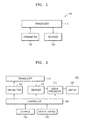
- FIG. 1 is a block diagram of an ultrasonic diagnostic apparatus 100 according to an exemplary embodiment.
- the ultrasonic diagnostic apparatus 100 may include a transducer 110, a transmitter 120, and a receiver 130.
- the ultrasonic diagnostic apparatus 100 may transmit an ultrasound wave in the form of a plane wave.
- the plane wave may be a steered plane wave.
- the plane wave may be a pulse type or chirp type plane wave, and apodization may be applied.
- an ultrasound wave in the form of a plane wave may also be simply referred to as a plane wave.
- the transducer 110 transmits ultrasound waves to an object and receives ultrasound echo signals reflected from the object.
- the transducer 110 may include a plurality of transducer elements for converting electrical signals into acoustic energy (or vice versa).
- the plurality of transducer elements may be arranged in a one-dimensional (1 D) or two-dimensional (2D) array.
- the transducer 110 may be realized as a piezoelectric micromachined ultrasonic transducer (pMUT) that interconverts an ultrasound wave and an electrical signal due to a change in pressure caused by vibration, a capacitive micromachined ultrasonic transducer (cMUT) that interconverts an ultrasound wave and an electrical signal due to a change in capacitance, a magnetic micromachined ultrasonic transducer (mMUT) that interconvert an ultrasound wave and an electrical signal due to a change in magnetic field, and an optical ultrasonic detector that interconvert an ultrasound wave and an electrical signal due to a change in optical properties.
- pMUT piezoelectric micromachined ultrasonic transducer
- cMUT capacitive micromachined ultrasonic transducer
- mMUT magnetic micromachined ultrasonic transducer
- an optical ultrasonic detector that interconvert an ultrasound wave and an electrical signal due to a change in optical properties.
- the transmitter 120 supplies a driving signal to the transducer 110.
- the transmitter 120 may control the transducer 110 so as to allow a plurality of plane waves to be transmitted through a plurality of sub-apertures.
- An aperture may be defined as a size of the transducer 110 for transmitting an ultrasound wave.
- the transmitter 120 according to an exemplary embodiment does not transmit a single wave by using all of the transducer elements included in the transducer 110 but may divide the transducer elements into several groups and control the transducer 110 so that each group of transducer elements transmits a wave. Thus, a size of each group of transducer elements for transmitting a wave may be defined as a sub-aperture.
- the transmitter 120 may control the transducer 110 to transmit a plurality of plane waves to an object through spatially separated sub-apertures. A method of transmitting a plurality of plane waves through a plurality of sub-apertures will be described in detail below.
- the receiver 130 performs analog-to-digital conversion on a signal received from the transducer 110 to produce a digital signal and performs beamforming on the digital signal to form a focused reception signal.
- the receiver 130 may generate ultrasound data by using the focused reception signal. Since the transducer 110 transmits a plurality of plane waves through a plurality of sub-apertures and receives echo signals corresponding to the plurality of plane waves, the receiver 130 needs to add together the echo signals corresponding to the plurality of plane waves in order to acquire an image.
- the receiver 130 may include only a storage for storing the signal received from the transducer 110.
- an ultrasound probe necessarily includes the transducer 110
- at least some of the components in the transmitter 120 and the receiver 130 may be included in a device other than the ultrasound probe.
- at least one of the transmitter 120 and the receiver 130 may be connected to the transducer 110 via a connector or network.
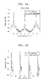
- FIG. 2 is a block diagram of an ultrasonic diagnostic apparatus 200 according to another exemplary embodiment.
- the ultrasonic diagnostic apparatus 200 may include, in addition to the transducer 110, the transmitter 120, and the receiver 130 shown in FIG. 1 , a signal processor 220 for processing signals applied by the receiver 130 and generating an image, a display 230 for displaying the image, a user interface 240 for receiving a user command, a storage 250 for storing various types of information, and a controller 260 for controlling overall operations of the ultrasonic diagnostic apparatus 200.
- the signal processor 220 may process ultrasound data generated by the receiver 130 and generate an ultrasound image.
- An ultrasound image may be at least one of a brightness (B) mode image representing a magnitude of an ultrasound echo signal reflected from an object as brightness, a Doppler (D) mode image showing an image of a moving object in the form of a spectrum by using a Doppler effect, a motion (M) mode image representing movement of an object at a specific position over time, an elastic mode image visualizing a difference between responses when compression is or is not applied to an object as an image, and a color (C) mode image representing a velocity of a moving object in colors by using a Doppler effect.
- B brightness
- D Doppler
- M motion
- C color
- the ultrasound image according to an exemplary embodiment of the present invention may include images taken in all dimensions such as 1 D, 2D, three-dimension (3D), four-dimension (4D), etc.
- the display 230 displays information that is processed by the ultrasonic diagnostic apparatus 200.
- the display 230 may display an ultrasound image generated by the signal processor 220 as well as a graphical user interface (GUI) for requesting a user input.
- GUI graphical user interface
- the display 230 may include at least one of a liquid crystal display (LCD), a thin film transistor-LCD (TFT-LCD), an organic light-emitting diode (OLED), a flexible display, a 3D display, and an electrophoretic display.
- the ultrasonic diagnostic apparatus 100 may include two or more displays 230 according to exemplary embodiments of the present invention.
- the user interface 240 refers to a means via which a user inputs data for controlling the ultrasonic diagnostic apparatus 100.
- the user interface 240 may include a keypad, a mouse, a touch panel, and a track ball.
- the user interface 240 is not limited thereto, and may further include various other input elements such as a jog wheel and a jog switch.
- the touch panel may detect both a real touch where a pointer actually touches a screen and a proximity touch where the pointer approaches the screen while being separated from the screen by less than a predetermined distance.
- the term 'pointer' means a tool for touching a particular portion on or near the touch panel. Examples of the pointer may include a stylus pen and a body part such as a finger.
- the touch panel may be realized as a touch screen that forms a layer structure with the display 230.
- the touch screen may be implemented as various types such as capacitive overlay, resistive overlay, infrared beam, surface acoustic wave, integral strain gauge, and piezoelectric touch screens.
- the touch screen is very useful because it functions as both the display 230 and the user interface 240.
- various sensors may be disposed within or near the touch panel so as to sense a touch.
- a tactile sensor is an example of the sensors designed for the touch panel to sense a touch.
- the tactile sensor is used to sense a touch of a particular object to a same or greater degree than the degree to which a human can sense the touch.
- the tactile sensor may detect various pieces of information including the toughness of a contact surface, the hardness of an object to be touched, and the temperature of a point to be touched.
- a proximity sensor is another example of the sensors designed for the touch panel to sense a touch.
- the proximity sensor is a sensor that detects the presence of an object that is approaching or is located near a predetermined detection surface by using the force of an electromagnetic field or infrared light without any mechanical contact.
- Examples of the proximity sensor include a transmissive photoelectric sensor, a direct reflective photoelectric sensor, a mirror reflective photoelectric sensor, a high-frequency oscillation proximity sensor, a capacitive proximity sensor, a magnetic proximity sensor, and an infrared proximity sensor.
- the storage 250 stores various types of information that are processed by the ultrasonic diagnostic apparatus 100.
- the storage 250 may store medical data related to diagnosis of the object, such as images, and algorithms or programs that are executed in the ultrasonic diagnostic apparatus 100.
- the storage 250 may include at least one storage medium from among a flash memory-type storage medium, a hard disk-type storage medium, a multimedia card micro-type storage medium, card-type memories (e.g., an SD card, an XD memory, and the like), a Random Access Memory (RAM), a Static Random Access Memory (SRAM), a Read-Only Memory (ROM), an Electrically Erasable Programmable ROM (EEPROM), a PROM, a magnetic memory, a magnetic disc, and an optical disc.
- the ultrasonic diagnostic apparatus 100 may utilize web storage or a cloud server that functions as the storage 250 online.
- the controller 260 controls the overall operations of the ultrasonic diagnostic apparatus 100.
- the controller 260 may control operations of the ultrasonic diagnostic apparatus 100 of FIG. 2 , the signal processor 220, and the display 230.
- the controller 260 may control the signal processor 220 to generate an image by using a user command received via the user interface 240 or programs stored in the storage 250.
- the controller 260 may also control the image generated by the signal processor 220 to be displayed on the display 230.
- the transducer 110 transmits and receives a wave such as a plane wave, and the transmitter 120 applies an electrical signal to the transducer 110 in order for the transducer 110 to transmit a wave.
- the transducer 110 may apply an electrical signal corresponding to the received wave to the receiver 130.
- transmission of a plane wave by the ultrasonic diagnostic apparatus may mean that the transmitter 120 controls the transducer 110 to transmit the plane wave.
- Reception and processing of a plane wave by the ultrasonic diagnostic apparatus may mean that the transducer 110 receives an echo signal corresponding to a plane wave and the receiver 130 stores an electrical signal corresponding to the echo signal or generates ultrasound data based on the electrical signal.
- the transducer 110, the transmitter 120, and the receiver 130 are not individually named but simply referred to as the ultrasonic diagnostic apparatus.
- An ultrasonic diagnostic apparatus may transmit an ultrasound wave in the form of a plane wave.
- a plane wave may be generated using a time delay or phase delay of the transmitter 120.
- the use of a plane wave has advantages of generating an ultrasound image at a high frame rate and acquiring an ultrasound image of a wide area of an object.
- an echo signal may suffer a high clutter level since the plane wave has a high degree of scattering
- the ultrasonic diagnostic apparatus may transmit a plurality of plane waves through a plurality of sub-apertures and receive echo signals corresponding to the plurality of plane waves, thereby generating an ultrasound image on a frame-by-frame basis.
- a clutter level may be reduced
- FIG. 3 is a reference diagram for explaining coordinates of an ultrasonic diagnostic apparatus.
- the resolution of an ultrasound image may be determined, based on a transducer element within the transducer 110, as resolutions in an axial direction 2 defined as a direction in which a transmission wave travels, in a lateral direction 4 defined as a width direction of the transducer element, and in an elevation direction 6 defined as a height direction of the transducer element.
- the method of operating an ultrasonic diagnostic apparatus will be described below based on the coordinates.
- FIG. 4 is a reference diagram for explaining a method of transmitting a plurality of plane waves in a plurality of sub-apertures according to an exemplary embodiment.
- a transducer 110 of an ultrasonic diagnostic apparatus may include first and second transducers 110a and 110b spatially separated from each other.
- the first and second transducers 110a and 110b may be arranged parallel to each other.
- Each of the first and second transducers 110a and 110b may include one or more transducer elements 112.
- the transmitter 120 may control the first and second transducers 110a and 110b to transmit first and second plane waves Tx1 and Tx2, respectively. Sizes of the first and second transducers 110a and 110b for transmitting the first and second plane waves may be first and second sub-apertures, respectively.
- the transmitter 120 may control the first and second transducers 110a and 110b so as to allow the first and second plane waves Tx1 and Tx2 to be consecutively transmitted one by one. In this case, the first and second plane waves Tx1 and Tx2 may have the same frequency band but are not limited thereto.
- the transmitter 120 may control the first transducer 110a to transmit the first plane wave Tx1 at a first time, and after the first time has lapsed, control the second transducer 110b to transmit the second plane wave Tx2 at a second time.
- the first transducer 110a may receive an echo signal Rx1 generated in response to the first plane wave.
- the second transducer 110b may receive an echo signal Rx2 generated in response to the second plane wave.
- the receiver 130 may delay the timing of an electrical signal corresponding to an echo signal generated in response to the first plane wave and synthesize the electrical signal with an electrical signal corresponding to an echo signal generated in response to the second plane wave, thereby generating one piece of image data.
- a steering angle ⁇ 1 for the first plane wave Tx1 may be different from a steering angle ⁇ 2 for the second plane wave Tx2.
- the steering angles ⁇ 1 and ⁇ 2 for the first and second plane waves Tx1 and Tx2 may be symmetric with respect to an axial direction Z.
- the steering angle ⁇ 1 for the first plane wave Tx1 being transmitted by the first transducer 110a may be equal to a reception angle ⁇ 1 for the echo signal Rx1 generated in response to the first plane wave.
- the steering angle ⁇ 2 for the second plane wave Tx2 being transmitted by the second transducer 110b may be equal to a reception angle ⁇ 2 for the echo signal Rx2 generated in response to the second plane wave.
- a clutter level may be reduced by minimizing an aperture through which a plane wave is transmitted.
- Table 1 shows a result of simulation for determining whether the clutter level was reduced. Parameters used in the simulation are summarized in Table 1 below.
- a center frequency and a sampling frequency of a plane wave transmitted by the transducer 110 were 9 MHz and 72 MHz, respectively.
- the number of transducer elements in the transducer 110 was 192, and a transducer element had a height of 5 mm and a pitch of 0.2 mm.
- a steering angle was ⁇ 20°, and three targets were arranged at positions that were 50 mm away from the transducer 110 in an axial direction of the transducer element and were -14 mm, 0 mm, and 14 mm away from the transducer 110 in a lateral direction, respectively.
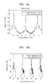
- FIGS. 5A and 5B are reference diagrams for explaining the resolution of an ultrasound image acquired using a plane wave.
- a dashed line represents a magnitude of a signal received after transmission of a plane wave through one aperture while a solid line represents a magnitude of a signal received after transmission of four plane waves through four sub-apertures.
- FIGS. 5A and 5B when plane waves are transmitted in a plurality of sub-apertures, magnitudes of echo signals corresponding to the plane waves are significantly reduced in a region where a target does not exist. It can be seen that an ultrasound image acquired by transmitting a plurality of plane waves through a plurality of sub-apertures contains less noise than an ultrasound image acquired by transmitting a plane wave through one aperture.
- Transmitting and receiving a plurality of plane waves at different times may lower a frame rate.
- an ultrasonic diagnostic apparatus may transmit a plurality of plane waves through a plurality of sub-apertures simultaneously. Even when the plurality of sub-apertures are physically separated, the plurality of plane waves may interfere with one another.
- the transmitter 120 of the ultrasonic diagnostic apparatus may control the transducer 110 so as to allow a plurality of chirp-type plane waves to be simultaneously transmitted. By transmitting the plurality of plane waves at the same time, it is possible to maintain the same frame rate as that achieved by transmitting one plane wave.
- the transmitter 120 may control the transducer 110 so that the first transducer 110a of the transducer 110 shown in FIG. 3 may transmit a first plane wave Tx1 of an up-chirp type and the second transducer 110b may transmit a second plane wave Tx2 of a down-chirp type.
- the first and second plane waves Tx1 and Tx2 may have the same frequency band and be transmitted at the same time. Since a plurality of plane waves are transmitted and received at the same time, the same frame rate may be maintained. Furthermore, since the first and second plane waves Tx1 and Tx2 are of opposite chirp types, it is possible to reduce the crosstalk between the plurality of first and second plane waves.
- the receiver 130 may compress an echo signal received via the transducer 110. Since the transducer 110 receives a plurality of chirp-type plane waves simultaneously, the receiver 130 may compress a signal received from the transducer 110 according to the directional characteristics of an echo signal. The compression may be pulse compression.
- the receiver 130 may compress the received echo signal by using a down-chirp signal. If the received echo signal is of a down-chirp type, the receiver 130 may compress the received echo signal by using an up-chirp signal. In detail, the receiver 130 may compress an echo signal corresponding to a first plane wave, which is received via a first transducer 110, by using a down-chirp signal. The receiver 130 may compress an echo signal corresponding to a second plane wave, which is received via a second transducer 110, by using an up-chirp signal.
- a level of a signal output from the receiver 130 may be lowered, and accordingly, the time duration taken to generate a frame image may be reduced.
- exemplary embodiments are not limited thereto, and the receiver 130 may compress an echo signal by using the same type of chirp signal.
- the ultrasonic diagnostic apparatus may generate a chirp-type plane wave combined with a window function. If the window function is combined with a chirp signal as described above, a sidelobe level of a compressed signal created by the receiver 130 may be reduced.
- the window function may be a Hanning window, but is not limited thereto. Some examples of the window function may be a Blackman window, a cosine window, a Gaussian window, etc.
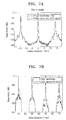
- FIGS. 6A and 6B are reference diagrams for explaining an ultrasound image acquired using a chirp signal.
- a dashed line represents a magnitude of a signal received after transmission of pulse-type plane waves through four sub-apertures while a solid line represents a magnitude of a signal received after transmission of chirp-type plane waves through the four sub-apertures.
- the use of a chirp-type plane wave may reduce a clutter level by about 8 decibels (dB) compared to the use of a pulse-type plane wave.
- the transmitter 120 may apply apodization to at least one of first and second plane waves Tx1 and Tx2, thereby reducing a fringing effect between the plane waves.
- a Hanning window may be used as an apodization function, but exemplary embodiments are not limited thereto.
- Another window function such as a rectangular window may also be used as an apodization function.
- FIGS. 7A and 7B are reference diagrams for explaining an ultrasound image acquired by applying apodization.
- a dashed line represents a magnitude of a signal received after transmission of chirp-type plane waves through four sub-apertures while a solid line represents a magnitude of a signal received after transmission of chirp-type plane waves, to which apodization is applied, through the four sub-apertures.
- the use of a chirp-type plane wave to which apodization is applied may further reduce a clutter level compared to the use of a chirp-type plane wave to which apodization is not applied.
- FIGS. 7A and 7B show that apodization is applied to a chirp-type plane wave
- exemplary embodiments are not limited thereto.
- Apodization may be applied to another type of plane wave.
- FIG. 8 is a flowchart of an ultrasonic diagnostic method according to an exemplary embodiment.
- an ultrasonic diagnostic apparatus may transmit a plurality of plane waves through a plurality of sub-apertures (S810) and receive a plurality of echo signals respectively corresponding to the plurality of plane waves from an object (S820).
- the plurality of plane waves may be transmitted sequentially or simultaneously.
- a frame rate may be lowered.
- interference between plane waves occurs.
- at least one of the plurality of plane waves may be of a chirp type.
- a first plane wave from among the plurality of plane waves may be an up-chirp type plane wave while a second plane wave contiguous to the first plane wave may be a down-chirp type plane wave.
- apodization may be applied to at least one of the plurality of plane waves.
- a clutter level may be further reduced.
- the method of transmitting and receiving a plane wave and the signal processing method described above may be applied to the ultrasonic diagnostic method.
- a transducer element for transmitting or receiving a first plane wave is different from a transducer element for transmitting or receiving a second plane wave when an ultrasonic diagnostic apparatus according to an exemplary embodiment transmits a plurality of plane waves
- One transducer element may transmit some of the first and second plane waves in order for the ultrasonic diagnostic apparatus to transmit a plurality of spatially separated plane waves.
- ultrasound waves are plane waves, exemplary embodiments are not limited thereto, and the ultrasound waves may be defocused ultrasound waves. That is, a transducer may transmit a defocused ultrasound wave by transmitting an ultrasound wave by varying a phase.
Landscapes
- Physics & Mathematics (AREA)
- Engineering & Computer Science (AREA)
- Health & Medical Sciences (AREA)
- Life Sciences & Earth Sciences (AREA)
- General Physics & Mathematics (AREA)
- Remote Sensing (AREA)
- Radar, Positioning & Navigation (AREA)
- General Health & Medical Sciences (AREA)
- Pathology (AREA)
- Computer Networks & Wireless Communication (AREA)
- Analytical Chemistry (AREA)
- Acoustics & Sound (AREA)
- Immunology (AREA)
- Biochemistry (AREA)
- Chemical & Material Sciences (AREA)
- Nuclear Medicine, Radiotherapy & Molecular Imaging (AREA)
- Veterinary Medicine (AREA)
- Medical Informatics (AREA)
- Heart & Thoracic Surgery (AREA)
- Molecular Biology (AREA)
- Biophysics (AREA)
- Public Health (AREA)
- Radiology & Medical Imaging (AREA)
- Biomedical Technology (AREA)
- Animal Behavior & Ethology (AREA)
- Surgery (AREA)
- Gynecology & Obstetrics (AREA)
- Ultra Sonic Daignosis Equipment (AREA)
Abstract
Description
- The present invention relates to an ultrasonic diagnostic apparatus and method.
- In general, ultrasonic diagnostic apparatuses transmit ultrasound waves to an object such as a human or animal and detect echo signals reflected from the object, thereby displaying a tomographic image of a tissue inside the object on a monitor and providing information necessary for diagnosis of the object. By performing the above process, the ultrasonic diagnostic apparatuses have been used for medical purposes such as detecting foreign substances within a living organism, assessing injuries, monitoring a tumor, and observing a fetus.
- Ultrasound may be classified mainly into focused ultrasound and plane-wave ultrasound. Focused ultrasound has the advantage of providing high resolution imaging but requires a large number of transmissions. On the other hand, plane-wave ultrasound is advantageous in acquiring an ultrasound image of a large area with a relatively small number of transmissions. Furthermore, the use of plane-wave ultrasound allows relatively simple calculation of a focusing delay for focus synthesis.
- However, an ultrasound image acquired using plane-wave ultrasound may show a higher clutter level than when using focused ultrasound. As the clutter level of an ultrasound image increases, the contrast resolution of the ultrasound image may be degraded.
- The present invention provides an ultrasonic diagnostic apparatus and method of reducing a clutter level.
- According to an aspect of the present invention, there is provided an ultrasonic diagnostic apparatus including: a transducer configured to perform interconversion between an acoustic wave and an electrical signal; and a transmitter for controlling the transducer so as to allow a plurality of plane waves to be transmitted through a plurality of sub-apertures.
- The plurality of plane waves may be steered plane waves.
- Furthermore, the plurality of plane waves may be transmitted sequentially.
- In addition, the plurality of plane waves may be transmitted simultaneously.
- Furthermore, apodization may be applied to at least one of the plurality of plane waves.
- In addition, a window function may be applied to at least one of the plurality of plane waves as apodization.
- Furthermore, at least one of the plurality of plane waves may include a chirp-type plane wave.
- In addition, a first plane wave from among the plurality of plane waves may be an up-chirp type plane wave, and a second plane wave adjacent to the first plane wave may be a down-chirp type plane wave.
- Furthermore, the transducer may receive echo signals corresponding to the plurality of plane waves from an object. The ultrasonic diagnostic apparatus may further include a receiver configured to receive electrical signals corresponding to the echo signals via the transducer.
- Furthermore, the receiver may compress the electrical signals corresponding to the echo signals when the echo signals originate from chirp type plane waves.
- In addition, the receiver may compress the electrical signals by using a signal of a chirp type opposite to that of the chirp-type plane waves.
- Furthermore, the transducer may include: a first transducer configured to transmit a first plane wave through a first sub-aperture; and a second transducer spatially separated from the first transducer and configured to transmit a second plane wave through a second sub-aperture.
- Furthermore, the first and second plane waves may each have the same frequency band.
- Furthermore, a steering angle for the first plane wave may be different from a steering angle for the second plane wave.
- In addition, the steering angles for the first and second plane waves may be symmetric with respect to a direction in which an ultrasound wave travels.
- According to another aspect of the present invention, there is provided an ultrasonic diagnostic method including: transmitting, through a plurality of sub-apertures, a plurality of plane waves to an object; and receiving, from the object, a plurality of echo signals respectively corresponding to the plurality of plane waves.
- The plurality of plane waves may be transmitted simultaneously.
- Furthermore, apodization may be applied to at least one of the plurality of plane waves.
- Furthermore, at least one of the plurality of plane waves may include a chirp-type plane wave.
- In addition, a first plane wave from among the plurality of plane waves may be an up-chirp type plane wave, and a second plane wave adjacent to the first plane wave may be a down-chirp type plane wave.
- A clutter level may be reduced by using a plurality of plane waves transmitted through a plurality of sub-apertures.
- By using a chirp-type plane wave, it is possible to prevent a drop in a frame rate of the plane wave while reducing a clutter level.
- Furthermore, it is possible to reduce a fringing effect between plane waves by applying apodization to a plane wave.
-
-
FIG. 1 is a block diagram of an ultrasonic diagnostic apparatus according to an exemplary embodiment. -
FIG. 2 is a block diagram of ultrasonic diagnostic apparatus according to another exemplary embodiment; -
FIG. 3 is a reference diagram for explaining coordinates of an ultrasonic diagnostic apparatus. -
FIG. 4 is a reference diagram for explaining a method of transmitting a plurality of plane waves in a plurality of sub-apertures according to an exemplary embodiment. -
FIGS. 5A and 5B are reference diagrams for explaining a resolution of an ultrasound image acquired using a plane wave. -
FIGS. 6A and 6B are reference diagrams for explaining an ultrasound image acquired using a chirp signal. -
FIGS. 7A and 7B are reference diagrams for explaining an ultrasound image acquired by applying apodization. -
FIG. 8 is a flowchart of an ultrasonic diagnostic method according to an exemplary embodiment. - Hereinafter, preferred exemplary embodiments of the present invention will be described in detail with reference to the attached drawing in which the same or corresponding elements are denoted by the same reference numerals. Repeated descriptions of the same or corresponding elements are omitted.
- Throughout the specification, an "object" may include a human or an animal, or a part of a human or animal. For example, the object may include an organ such as the liver, the heart, the womb, the brain, a breast, or the abdomen, or a blood vessel.
-
FIG. 1 is a block diagram of an ultrasonicdiagnostic apparatus 100 according to an exemplary embodiment. Referring toFIG. 1 , the ultrasonicdiagnostic apparatus 100 may include atransducer 110, atransmitter 120, and areceiver 130. The ultrasonicdiagnostic apparatus 100 may transmit an ultrasound wave in the form of a plane wave. The plane wave may be a steered plane wave. Furthermore, the plane wave may be a pulse type or chirp type plane wave, and apodization may be applied. Hereinafter, an ultrasound wave in the form of a plane wave may also be simply referred to as a plane wave. - The
transducer 110 transmits ultrasound waves to an object and receives ultrasound echo signals reflected from the object. Thetransducer 110 may include a plurality of transducer elements for converting electrical signals into acoustic energy (or vice versa). The plurality of transducer elements may be arranged in a one-dimensional (1 D) or two-dimensional (2D) array. - The
transducer 110 may be realized as a piezoelectric micromachined ultrasonic transducer (pMUT) that interconverts an ultrasound wave and an electrical signal due to a change in pressure caused by vibration, a capacitive micromachined ultrasonic transducer (cMUT) that interconverts an ultrasound wave and an electrical signal due to a change in capacitance, a magnetic micromachined ultrasonic transducer (mMUT) that interconvert an ultrasound wave and an electrical signal due to a change in magnetic field, and an optical ultrasonic detector that interconvert an ultrasound wave and an electrical signal due to a change in optical properties. - The
transmitter 120 supplies a driving signal to thetransducer 110. Thetransmitter 120 may control thetransducer 110 so as to allow a plurality of plane waves to be transmitted through a plurality of sub-apertures. An aperture may be defined as a size of thetransducer 110 for transmitting an ultrasound wave. Thetransmitter 120 according to an exemplary embodiment does not transmit a single wave by using all of the transducer elements included in thetransducer 110 but may divide the transducer elements into several groups and control thetransducer 110 so that each group of transducer elements transmits a wave. Thus, a size of each group of transducer elements for transmitting a wave may be defined as a sub-aperture. Thetransmitter 120 may control thetransducer 110 to transmit a plurality of plane waves to an object through spatially separated sub-apertures. A method of transmitting a plurality of plane waves through a plurality of sub-apertures will be described in detail below. - The
receiver 130 performs analog-to-digital conversion on a signal received from thetransducer 110 to produce a digital signal and performs beamforming on the digital signal to form a focused reception signal. Thereceiver 130 may generate ultrasound data by using the focused reception signal. Since thetransducer 110 transmits a plurality of plane waves through a plurality of sub-apertures and receives echo signals corresponding to the plurality of plane waves, thereceiver 130 needs to add together the echo signals corresponding to the plurality of plane waves in order to acquire an image. - In addition, when the
receiver 130 does not need to generate ultrasound data in real-time by using a signal received via thetransducer 110, thereceiver 130 may include only a storage for storing the signal received from thetransducer 110. - While an ultrasound probe necessarily includes the
transducer 110, at least some of the components in thetransmitter 120 and thereceiver 130 may be included in a device other than the ultrasound probe. For example, at least one of thetransmitter 120 and thereceiver 130 may be connected to thetransducer 110 via a connector or network. -
FIG. 2 is a block diagram of an ultrasonicdiagnostic apparatus 200 according to another exemplary embodiment. Referring toFIG. 2 , the ultrasonicdiagnostic apparatus 200 may include, in addition to thetransducer 110, thetransmitter 120, and thereceiver 130 shown inFIG. 1 , asignal processor 220 for processing signals applied by thereceiver 130 and generating an image, adisplay 230 for displaying the image, auser interface 240 for receiving a user command, astorage 250 for storing various types of information, and acontroller 260 for controlling overall operations of the ultrasonicdiagnostic apparatus 200. - The
signal processor 220 may process ultrasound data generated by thereceiver 130 and generate an ultrasound image. An ultrasound image may be at least one of a brightness (B) mode image representing a magnitude of an ultrasound echo signal reflected from an object as brightness, a Doppler (D) mode image showing an image of a moving object in the form of a spectrum by using a Doppler effect, a motion (M) mode image representing movement of an object at a specific position over time, an elastic mode image visualizing a difference between responses when compression is or is not applied to an object as an image, and a color (C) mode image representing a velocity of a moving object in colors by using a Doppler effect. Since an ultrasound image is generated by using a method well known in the related art, a detailed description thereof will be omitted here. Accordingly, the ultrasound image according to an exemplary embodiment of the present invention may include images taken in all dimensions such as 1 D, 2D, three-dimension (3D), four-dimension (4D), etc. - The
display 230 displays information that is processed by the ultrasonicdiagnostic apparatus 200. For example, thedisplay 230 may display an ultrasound image generated by thesignal processor 220 as well as a graphical user interface (GUI) for requesting a user input. - The
display 230 may include at least one of a liquid crystal display (LCD), a thin film transistor-LCD (TFT-LCD), an organic light-emitting diode (OLED), a flexible display, a 3D display, and an electrophoretic display. The ultrasonicdiagnostic apparatus 100 may include two ormore displays 230 according to exemplary embodiments of the present invention. - The
user interface 240 refers to a means via which a user inputs data for controlling the ultrasonicdiagnostic apparatus 100. Theuser interface 240 may include a keypad, a mouse, a touch panel, and a track ball. Theuser interface 240 is not limited thereto, and may further include various other input elements such as a jog wheel and a jog switch. - The touch panel may detect both a real touch where a pointer actually touches a screen and a proximity touch where the pointer approaches the screen while being separated from the screen by less than a predetermined distance. In the present specification, the term 'pointer' means a tool for touching a particular portion on or near the touch panel. Examples of the pointer may include a stylus pen and a body part such as a finger.
- Furthermore, the touch panel may be realized as a touch screen that forms a layer structure with the
display 230. The touch screen may be implemented as various types such as capacitive overlay, resistive overlay, infrared beam, surface acoustic wave, integral strain gauge, and piezoelectric touch screens. The touch screen is very useful because it functions as both thedisplay 230 and theuser interface 240. - Although not shown in
FIG. 2 , various sensors may be disposed within or near the touch panel so as to sense a touch. A tactile sensor is an example of the sensors designed for the touch panel to sense a touch. The tactile sensor is used to sense a touch of a particular object to a same or greater degree than the degree to which a human can sense the touch. The tactile sensor may detect various pieces of information including the toughness of a contact surface, the hardness of an object to be touched, and the temperature of a point to be touched. - A proximity sensor is another example of the sensors designed for the touch panel to sense a touch. The proximity sensor is a sensor that detects the presence of an object that is approaching or is located near a predetermined detection surface by using the force of an electromagnetic field or infrared light without any mechanical contact. Examples of the proximity sensor include a transmissive photoelectric sensor, a direct reflective photoelectric sensor, a mirror reflective photoelectric sensor, a high-frequency oscillation proximity sensor, a capacitive proximity sensor, a magnetic proximity sensor, and an infrared proximity sensor.
- The
storage 250 stores various types of information that are processed by the ultrasonicdiagnostic apparatus 100. For example, thestorage 250 may store medical data related to diagnosis of the object, such as images, and algorithms or programs that are executed in the ultrasonicdiagnostic apparatus 100. - The
storage 250 may include at least one storage medium from among a flash memory-type storage medium, a hard disk-type storage medium, a multimedia card micro-type storage medium, card-type memories (e.g., an SD card, an XD memory, and the like), a Random Access Memory (RAM), a Static Random Access Memory (SRAM), a Read-Only Memory (ROM), an Electrically Erasable Programmable ROM (EEPROM), a PROM, a magnetic memory, a magnetic disc, and an optical disc. Furthermore, the ultrasonicdiagnostic apparatus 100 may utilize web storage or a cloud server that functions as thestorage 250 online. - The
controller 260 controls the overall operations of the ultrasonicdiagnostic apparatus 100. In detail, thecontroller 260 may control operations of the ultrasonicdiagnostic apparatus 100 ofFIG. 2 , thesignal processor 220, and thedisplay 230. For example, thecontroller 260 may control thesignal processor 220 to generate an image by using a user command received via theuser interface 240 or programs stored in thestorage 250. Thecontroller 260 may also control the image generated by thesignal processor 220 to be displayed on thedisplay 230. - As described above, the
transducer 110 transmits and receives a wave such as a plane wave, and thetransmitter 120 applies an electrical signal to thetransducer 110 in order for thetransducer 110 to transmit a wave. When thetransducer 110 receives a wave, thetransducer 110 may apply an electrical signal corresponding to the received wave to thereceiver 130. Thus, transmission of a plane wave by the ultrasonic diagnostic apparatus may mean that thetransmitter 120 controls thetransducer 110 to transmit the plane wave. Reception and processing of a plane wave by the ultrasonic diagnostic apparatus may mean that thetransducer 110 receives an echo signal corresponding to a plane wave and thereceiver 130 stores an electrical signal corresponding to the echo signal or generates ultrasound data based on the electrical signal. Hereinafter, for convenience of explanation, thetransducer 110, thetransmitter 120, and thereceiver 130 are not individually named but simply referred to as the ultrasonic diagnostic apparatus. - An ultrasonic diagnostic apparatus according to an exemplary embodiment may transmit an ultrasound wave in the form of a plane wave. A plane wave may be generated using a time delay or phase delay of the
transmitter 120. The use of a plane wave has advantages of generating an ultrasound image at a high frame rate and acquiring an ultrasound image of a wide area of an object. However, when an object is diagnosed using a plane wave, an echo signal may suffer a high clutter level since the plane wave has a high degree of scattering - The ultrasonic diagnostic apparatus according to an exemplary embodiment may transmit a plurality of plane waves through a plurality of sub-apertures and receive echo signals corresponding to the plurality of plane waves, thereby generating an ultrasound image on a frame-by-frame basis. Thus, a clutter level may be reduced
- Before describing a method of operating an ultrasonic diagnostic apparatus according to an exemplary embodiment, coordinates of the ultrasonic diagnostic apparatus are defined.
FIG. 3 is a reference diagram for explaining coordinates of an ultrasonic diagnostic apparatus. As shown inFIG. 3 , the resolution of an ultrasound image may be determined, based on a transducer element within thetransducer 110, as resolutions in anaxial direction 2 defined as a direction in which a transmission wave travels, in alateral direction 4 defined as a width direction of the transducer element, and in anelevation direction 6 defined as a height direction of the transducer element. The method of operating an ultrasonic diagnostic apparatus will be described below based on the coordinates. -
FIG. 4 is a reference diagram for explaining a method of transmitting a plurality of plane waves in a plurality of sub-apertures according to an exemplary embodiment. As shown inFIG. 4 , atransducer 110 of an ultrasonic diagnostic apparatus may include first andsecond transducers second transducers second transducers more transducer elements 112. - The
transmitter 120 may control the first andsecond transducers second transducers transmitter 120 may control the first andsecond transducers - For example, the
transmitter 120 may control thefirst transducer 110a to transmit the first plane wave Tx1 at a first time, and after the first time has lapsed, control thesecond transducer 110b to transmit the second plane wave Tx2 at a second time. Furthermore, thefirst transducer 110a may receive an echo signal Rx1 generated in response to the first plane wave. Thesecond transducer 110b may receive an echo signal Rx2 generated in response to the second plane wave. Thereceiver 130 may delay the timing of an electrical signal corresponding to an echo signal generated in response to the first plane wave and synthesize the electrical signal with an electrical signal corresponding to an echo signal generated in response to the second plane wave, thereby generating one piece of image data. - A steering angle θ1 for the first plane wave Tx1 may be different from a steering angle θ2 for the second plane wave Tx2. For example, the steering angles θ1 and θ2 for the first and second plane waves Tx1 and Tx2 may be symmetric with respect to an axial direction Z. Furthermore, the steering angle θ1 for the first plane wave Tx1 being transmitted by the
first transducer 110a may be equal to a reception angle θ1 for the echo signal Rx1 generated in response to the first plane wave. The steering angle θ2 for the second plane wave Tx2 being transmitted by thesecond transducer 110b may be equal to a reception angle θ2 for the echo signal Rx2 generated in response to the second plane wave. As described above, when a plurality of plane waves are transmitted in a plurality of sub-apertures, a clutter level may be reduced by minimizing an aperture through which a plane wave is transmitted. - The following Table 1 shows a result of simulation for determining whether the clutter level was reduced. Parameters used in the simulation are summarized in Table 1 below.
[Table 1] SIMULATION PARAMETERS PARAMETERS Values Center frequency 9 MHz Sampling frequency 72 MHz Number of elements 192 Element height 5 mm Element pitch 0.2 mm Steering angle ±20° Number of TX 33 Target (axial) 10 to 70 mm (20-mm interval) Target (lateral) -14 mm, 0 mm, 14 mm - As shown in Table 1, a center frequency and a sampling frequency of a plane wave transmitted by the
transducer 110 were 9 MHz and 72 MHz, respectively. The number of transducer elements in thetransducer 110 was 192, and a transducer element had a height of 5 mm and a pitch of 0.2 mm. A steering angle was ±20°, and three targets were arranged at positions that were 50 mm away from thetransducer 110 in an axial direction of the transducer element and were -14 mm, 0 mm, and 14 mm away from thetransducer 110 in a lateral direction, respectively. -
FIGS. 5A and 5B are reference diagrams for explaining the resolution of an ultrasound image acquired using a plane wave. A dashed line represents a magnitude of a signal received after transmission of a plane wave through one aperture while a solid line represents a magnitude of a signal received after transmission of four plane waves through four sub-apertures. As shown inFIGS. 5A and 5B , when plane waves are transmitted in a plurality of sub-apertures, magnitudes of echo signals corresponding to the plane waves are significantly reduced in a region where a target does not exist. It can be seen that an ultrasound image acquired by transmitting a plurality of plane waves through a plurality of sub-apertures contains less noise than an ultrasound image acquired by transmitting a plane wave through one aperture. - Transmitting and receiving a plurality of plane waves at different times may lower a frame rate. To prevent a drop in a frame rate, an ultrasonic diagnostic apparatus according to an exemplary embodiment may transmit a plurality of plane waves through a plurality of sub-apertures simultaneously. Even when the plurality of sub-apertures are physically separated, the plurality of plane waves may interfere with one another.
- According to an exemplary embodiment, to reduce interference between a plurality of plane waves, the
transmitter 120 of the ultrasonic diagnostic apparatus may control thetransducer 110 so as to allow a plurality of chirp-type plane waves to be simultaneously transmitted. By transmitting the plurality of plane waves at the same time, it is possible to maintain the same frame rate as that achieved by transmitting one plane wave. - For example, the
transmitter 120 may control thetransducer 110 so that thefirst transducer 110a of thetransducer 110 shown inFIG. 3 may transmit a first plane wave Tx1 of an up-chirp type and thesecond transducer 110b may transmit a second plane wave Tx2 of a down-chirp type. The first and second plane waves Tx1 and Tx2 may have the same frequency band and be transmitted at the same time. Since a plurality of plane waves are transmitted and received at the same time, the same frame rate may be maintained. Furthermore, since the first and second plane waves Tx1 and Tx2 are of opposite chirp types, it is possible to reduce the crosstalk between the plurality of first and second plane waves. - Furthermore, the
receiver 130 may compress an echo signal received via thetransducer 110. Since thetransducer 110 receives a plurality of chirp-type plane waves simultaneously, thereceiver 130 may compress a signal received from thetransducer 110 according to the directional characteristics of an echo signal. The compression may be pulse compression. - For example, if a received echo signal is of an up-chirp type, the
receiver 130 may compress the received echo signal by using a down-chirp signal. If the received echo signal is of a down-chirp type, thereceiver 130 may compress the received echo signal by using an up-chirp signal. In detail, thereceiver 130 may compress an echo signal corresponding to a first plane wave, which is received via afirst transducer 110, by using a down-chirp signal. Thereceiver 130 may compress an echo signal corresponding to a second plane wave, which is received via asecond transducer 110, by using an up-chirp signal. As described above, when thereceiver 130 compresses an echo signal by using an opposite type of chirp signal, a level of a signal output from thereceiver 130 may be lowered, and accordingly, the time duration taken to generate a frame image may be reduced. However, exemplary embodiments are not limited thereto, and thereceiver 130 may compress an echo signal by using the same type of chirp signal. - Furthermore, the ultrasonic diagnostic apparatus may generate a chirp-type plane wave combined with a window function. If the window function is combined with a chirp signal as described above, a sidelobe level of a compressed signal created by the
receiver 130 may be reduced. For example, the window function may be a Hanning window, but is not limited thereto. Some examples of the window function may be a Blackman window, a cosine window, a Gaussian window, etc. -
FIGS. 6A and 6B are reference diagrams for explaining an ultrasound image acquired using a chirp signal. A dashed line represents a magnitude of a signal received after transmission of pulse-type plane waves through four sub-apertures while a solid line represents a magnitude of a signal received after transmission of chirp-type plane waves through the four sub-apertures. As shown inFIGS. 6A and 6B , the use of a chirp-type plane wave may reduce a clutter level by about 8 decibels (dB) compared to the use of a pulse-type plane wave. - When adjacent plane waves are perpendicular to each other, the crosstalk between the adjacent plane waves may not occur. However, when adjacent plane waves are not perpendicular to each other, the crosstalk may still be present in an axial direction. Thus, the
transmitter 120 may apply apodization to at least one of first and second plane waves Tx1 and Tx2, thereby reducing a fringing effect between the plane waves. A Hanning window may be used as an apodization function, but exemplary embodiments are not limited thereto. Another window function such as a rectangular window may also be used as an apodization function. -
FIGS. 7A and 7B are reference diagrams for explaining an ultrasound image acquired by applying apodization. A dashed line represents a magnitude of a signal received after transmission of chirp-type plane waves through four sub-apertures while a solid line represents a magnitude of a signal received after transmission of chirp-type plane waves, to which apodization is applied, through the four sub-apertures. As shown inFIGS. 7A and 7B , the use of a chirp-type plane wave to which apodization is applied may further reduce a clutter level compared to the use of a chirp-type plane wave to which apodization is not applied. - While
FIGS. 7A and 7B show that apodization is applied to a chirp-type plane wave, exemplary embodiments are not limited thereto. Apodization may be applied to another type of plane wave. -
FIG. 8 is a flowchart of an ultrasonic diagnostic method according to an exemplary embodiment. - Referring to
FIG. 8 , an ultrasonic diagnostic apparatus may transmit a plurality of plane waves through a plurality of sub-apertures (S810) and receive a plurality of echo signals respectively corresponding to the plurality of plane waves from an object (S820). - The plurality of plane waves may be transmitted sequentially or simultaneously. When the plurality of plane waves are transmitted sequentially, a frame rate may be lowered. However, when the plurality of plane waves are transmitted simultaneously, interference between plane waves occurs. To reduce the interference between plane waves, at least one of the plurality of plane waves may be of a chirp type. For example, a first plane wave from among the plurality of plane waves may be an up-chirp type plane wave while a second plane wave contiguous to the first plane wave may be a down-chirp type plane wave.
- Furthermore, apodization may be applied to at least one of the plurality of plane waves. By applying apodization to a plane wave, a clutter level may be further reduced. In addition, the method of transmitting and receiving a plane wave and the signal processing method described above may be applied to the ultrasonic diagnostic method.
- While it has been described above that a transducer element for transmitting or receiving a first plane wave is different from a transducer element for transmitting or receiving a second plane wave when an ultrasonic diagnostic apparatus according to an exemplary embodiment transmits a plurality of plane waves, this is only for convenience of explanation, and exemplary embodiments are not limited thereto. One transducer element may transmit some of the first and second plane waves in order for the ultrasonic diagnostic apparatus to transmit a plurality of spatially separated plane waves.
- Although the above-described ultrasound waves are plane waves, exemplary embodiments are not limited thereto, and the ultrasound waves may be defocused ultrasound waves. That is, a transducer may transmit a defocused ultrasound wave by transmitting an ultrasound wave by varying a phase.
- Many embodiments other than the above-described exemplary embodiments may be present in the claims of the present invention. As the present disclosure allows for various changes and numerous embodiments, exemplary embodiments are illustrated in the drawings and described in detail in the description. However, this is not intended to limit the present disclosure to a particular mode of practice, and it is to be appreciated that the present disclosure encompasses all changes, equivalents, and substitutes that do not depart from the spirit and technical scope thereof.
Claims (20)
- An ultrasonic diagnostic apparatus comprising:a transducer configured to perform interconversion between an acoustic wave and an electrical signal; anda transmitter configured to control the transducer so as to allow a plurality of plane waves to be transmitted through a plurality of sub-apertures.
- The ultrasonic diagnostic apparatus of claim 1, wherein the plurality of plane waves are steered plane waves.
- The ultrasonic diagnostic apparatus of claim 1, wherein the plurality of plane waves are transmitted sequentially.
- The ultrasonic diagnostic apparatus of claim 1, wherein the plurality of plane waves are transmitted simultaneously.
- The ultrasonic diagnostic apparatus of claim 1, wherein apodization is applied to at least one of the plurality of plane waves.
- The ultrasonic diagnostic apparatus of claim 5, wherein a window function is applied to at least one of the plurality of plane waves as apodization.
- The ultrasonic diagnostic apparatus of claim 1, wherein at least one of the plurality of plane waves comprises a chirp-type plane wave.
- The ultrasonic diagnostic apparatus of claim 7, wherein a first plane wave from among the plurality of plane waves is an up-chirp type plane wave, and
a second plane wave adjacent to the first plane wave is a down-chirp type plane wave. - The ultrasonic diagnostic apparatus of claim 1, wherein the transducer receives echo signals corresponding to the plurality of plane waves from an object,
the ultrasonic diagnostic apparatus further comprising a receiver configured to receive electrical signals corresponding to the echo signals via the transducer. - The ultrasonic diagnostic apparatus of claim 9, wherein the receiver compresses the electrical signals corresponding to the echo signals when the echo signals originate from chirp type plane waves.
- The ultrasonic diagnostic apparatus of claim 10, wherein the receiver compresses the electrical signals by using a signal of a chirp type opposite to that of the chirp-type plane waves.
- The ultrasonic diagnostic apparatus of claim 1, wherein the transducer comprises:a first transducer configured to transmit a first plane wave through a first sub-aperture; anda second transducer spatially separated from the first transducer and configured to transmit a second plane wave through a second sub-aperture.
- The ultrasonic diagnostic apparatus of claim 12, wherein the first and second plane waves each have a same frequency band.
- The ultrasonic diagnostic apparatus of claim 12, wherein a steering angle for the first plane wave is different from a steering angle for the second plane wave.
- The ultrasonic diagnostic apparatus of claim 14, wherein the steering angles for the first and second plane waves are symmetric with respect to a direction in which an ultrasound wave travels.
- An ultrasonic diagnostic method comprising:transmitting, through a plurality of sub-apertures, a plurality of plane waves to an object; andreceiving, from the object, a plurality of echo signals respectively corresponding to the plurality of plane waves.
- The ultrasonic diagnostic method of claim 16, wherein the plurality of plane waves are transmitted simultaneously.
- The ultrasonic diagnostic method of claim 16, wherein apodization is applied to at least one of the plurality of plane waves.
- The ultrasonic diagnostic method of claim 16, wherein at least one of the plurality of plane waves comprises a chirp-type plane wave.
- The ultrasonic diagnostic method of claim 19, wherein a first plane wave from among the plurality of plane waves is an up-chirp type plane wave, and
a second plane wave adjacent to the first plane wave is a down-chirp type plane wave.
Applications Claiming Priority (2)
| Application Number | Priority Date | Filing Date | Title |
|---|---|---|---|
| KR20130022374 | 2013-02-28 | ||
| PCT/KR2014/001685 WO2014133360A1 (en) | 2013-02-28 | 2014-02-28 | Ultrasonic diagnostic apparatus and method therefor |
Publications (3)
| Publication Number | Publication Date |
|---|---|
| EP2962643A1 true EP2962643A1 (en) | 2016-01-06 |
| EP2962643A4 EP2962643A4 (en) | 2016-10-19 |
| EP2962643B1 EP2962643B1 (en) | 2023-08-09 |
Family
ID=51428544
Family Applications (1)
| Application Number | Title | Priority Date | Filing Date |
|---|---|---|---|
| EP14756441.3A Active EP2962643B1 (en) | 2013-02-28 | 2014-02-28 | Ultrasonic diagnostic apparatus and method therefor |
Country Status (4)
| Country | Link |
|---|---|
| US (1) | US10448925B2 (en) |
| EP (1) | EP2962643B1 (en) |
| KR (1) | KR101611446B1 (en) |
| WO (1) | WO2014133360A1 (en) |
Cited By (2)
| Publication number | Priority date | Publication date | Assignee | Title |
|---|---|---|---|---|
| WO2021028078A1 (en) * | 2019-08-12 | 2021-02-18 | Ge Sensing & Inspection Technologies Gmbh | Fast pattern recognition using ultrasound |
| US12000966B2 (en) | 2018-11-19 | 2024-06-04 | Valeo Schalter Und Sensoren Gmbh | Method and analysis system for determining a state of a diaphragm of an ultrasound sensor |
Families Citing this family (8)
| Publication number | Priority date | Publication date | Assignee | Title |
|---|---|---|---|---|
| KR101683518B1 (en) * | 2015-07-22 | 2016-12-07 | 기아자동차 주식회사 | Contactless durability diagnosis apparatus and method |
| KR102438119B1 (en) * | 2015-10-16 | 2022-08-31 | 삼성전자주식회사 | Ultrasound device and ultrasound imaging method |
| CN107080556B (en) * | 2017-04-27 | 2020-05-08 | 苏州佳世达电通有限公司 | Ultrasonic image detection method and system |
| US11350909B2 (en) * | 2018-04-17 | 2022-06-07 | California Institute Of Technology | Cross amplitude modulation ultrasound pulse sequence |
| US12442918B2 (en) * | 2021-05-04 | 2025-10-14 | Cloudstream Medical Imaging, Inc. | Acquisition and processing of V-wave ultrasound data using a linear or curved array transducer |
| NL2035960B1 (en) * | 2023-10-04 | 2025-04-11 | Univ Delft Tech | Method and device for imaging a medium |
| EP4789039A1 (en) | 2023-10-04 | 2026-08-12 | Technische Universiteit Delft | Method and device for imaging a medium |
| CN119675595A (en) * | 2024-11-28 | 2025-03-21 | 中国水产科学研究院渔业机械仪器研究所 | Signal processing method, device, equipment, medium and product for dual-channel positive and negative frequency modulation |
Family Cites Families (19)
| Publication number | Priority date | Publication date | Assignee | Title |
|---|---|---|---|---|
| US6551246B1 (en) | 2000-03-06 | 2003-04-22 | Acuson Corporation | Method and apparatus for forming medical ultrasound images |
| JP3584883B2 (en) * | 2001-01-17 | 2004-11-04 | 日本電気株式会社 | Synthetic aperture sonar and synthetic aperture processing method |
| KR100406098B1 (en) | 2001-12-26 | 2003-11-14 | 주식회사 메디슨 | Ultrasound imaging system and method based on simultaneous multiple transmit-focusing using the weighted orthogonal chirp signals |
| US6780154B2 (en) * | 2002-01-17 | 2004-08-24 | Siemens Medical Solutions Usa, Inc. | Segmented handheld medical ultrasound system and method |
| US6685641B2 (en) * | 2002-02-01 | 2004-02-03 | Siemens Medical Solutions Usa, Inc. | Plane wave scanning reception and receiver |
| US7837626B2 (en) * | 2005-08-05 | 2010-11-23 | Siemens Medical Solutions Usa, Inc. | Contrast agent manipulation with medical ultrasound imaging |
| US7963919B2 (en) * | 2005-12-07 | 2011-06-21 | Siemens Medical Solutions Usa, Inc. | Ultrasound imaging transducer array for synthetic aperture |
| US8490489B2 (en) * | 2006-11-10 | 2013-07-23 | Siemens Medical Solutions Usa, Inc. | Transducer array imaging system |
| US20080119735A1 (en) * | 2006-11-20 | 2008-05-22 | Sonowise, Inc. | Ultrasound imaging system and method with offset alternate-mode line |
| US8254654B2 (en) | 2007-10-31 | 2012-08-28 | University Of Southern California | Sidelobe suppression in ultrasound imaging using dual apodization with cross-correlation |
| KR101024851B1 (en) | 2007-12-04 | 2011-03-31 | 주식회사 메디슨 | Ultrasound system and method for forming BC-mode images |
| US9117439B2 (en) | 2008-03-13 | 2015-08-25 | Supersonic Imagine | Method and apparatus for ultrasound synthetic imagining |
| US8133182B2 (en) * | 2008-09-09 | 2012-03-13 | Siemens Medical Solutions Usa, Inc. | Multi-dimensional transducer array and beamforming for ultrasound imaging |
| JP5247322B2 (en) | 2008-09-12 | 2013-07-24 | 株式会社日立メディコ | Ultrasonic imaging device |
| US8343050B2 (en) | 2009-05-04 | 2013-01-01 | Siemens Medical Solutions Usa, Inc. | Feedback in medical ultrasound imaging for high intensity focused ultrasound |
| US8633916B2 (en) | 2009-12-10 | 2014-01-21 | Apple, Inc. | Touch pad with force sensors and actuator feedback |
| WO2012029460A1 (en) * | 2010-08-31 | 2012-03-08 | 株式会社日立メディコ | Image reconstruction method and device |
| US8900145B2 (en) * | 2011-03-10 | 2014-12-02 | University Of Washington Through Its Center For Commercialization | Ultrasound systems and methods for real-time noninvasive spatial temperature estimation |
| CN107028623B (en) | 2012-02-21 | 2020-09-01 | 毛伊图像公司 | Determining Material Stiffness Using Porous Ultrasound |
-
2014
- 2014-02-28 EP EP14756441.3A patent/EP2962643B1/en active Active
- 2014-02-28 KR KR1020140024652A patent/KR101611446B1/en active Active
- 2014-02-28 WO PCT/KR2014/001685 patent/WO2014133360A1/en not_active Ceased
- 2014-02-28 US US14/771,272 patent/US10448925B2/en active Active
Cited By (2)
| Publication number | Priority date | Publication date | Assignee | Title |
|---|---|---|---|---|
| US12000966B2 (en) | 2018-11-19 | 2024-06-04 | Valeo Schalter Und Sensoren Gmbh | Method and analysis system for determining a state of a diaphragm of an ultrasound sensor |
| WO2021028078A1 (en) * | 2019-08-12 | 2021-02-18 | Ge Sensing & Inspection Technologies Gmbh | Fast pattern recognition using ultrasound |
Also Published As
| Publication number | Publication date |
|---|---|
| US10448925B2 (en) | 2019-10-22 |
| KR20140108181A (en) | 2014-09-05 |
| US20160113625A1 (en) | 2016-04-28 |
| WO2014133360A1 (en) | 2014-09-04 |
| EP2962643B1 (en) | 2023-08-09 |
| KR101611446B1 (en) | 2016-04-26 |
| EP2962643A4 (en) | 2016-10-19 |
Similar Documents
| Publication | Publication Date | Title |
|---|---|---|
| EP2962643B1 (en) | Ultrasonic diagnostic apparatus and method therefor | |
| US20260123917A1 (en) | Determining material stiffness using multiple aperture ultrasound | |
| EP3277187B1 (en) | Ultrasound imaging methods for detecting object motion | |
| JP7132915B2 (en) | Ultrasound system with tissue type analyzer | |
| US10617384B2 (en) | M-mode ultrasound imaging of arbitrary paths | |
| EP3199251B1 (en) | Ultrasonic transducer and ultrasonic probe including the same | |
| US20150196276A1 (en) | Ultrasonic probe and method of manufacturing the same | |
| EP3469396A1 (en) | Row-column addressed 2-d array with a double curved surface | |
| US11116481B2 (en) | Ultrasound diagnostic apparatus and control method of ultrasound diagnostic apparatus | |
| KR20160085016A (en) | Ultrasound diagnostic apparatus and control method for the same | |
| KR20180096342A (en) | Ultrasound probe and manufacturing method for the same | |
| EP2902116A2 (en) | Ultrasonic probe and method of manufacturing the same | |
| HK1202038B (en) | Determining material stiffness using multiple aperture ultrasound |
Legal Events
| Date | Code | Title | Description |
|---|---|---|---|
| PUAI | Public reference made under article 153(3) epc to a published international application that has entered the european phase |
Free format text: ORIGINAL CODE: 0009012 |
|
| 17P | Request for examination filed |
Effective date: 20150928 |
|
| AK | Designated contracting states |
Kind code of ref document: A1 Designated state(s): AL AT BE BG CH CY CZ DE DK EE ES FI FR GB GR HR HU IE IS IT LI LT LU LV MC MK MT NL NO PL PT RO RS SE SI SK SM TR |
|
| AX | Request for extension of the european patent |
Extension state: BA ME |
|
| DAX | Request for extension of the european patent (deleted) | ||
| A4 | Supplementary search report drawn up and despatched |
Effective date: 20160915 |
|
| RIC1 | Information provided on ipc code assigned before grant |
Ipc: G01N 29/14 20060101ALI20160909BHEP Ipc: A61B 8/14 20060101ALI20160909BHEP Ipc: G01S 7/52 20060101ALI20160909BHEP Ipc: G01S 15/89 20060101AFI20160909BHEP |
|
| STAA | Information on the status of an ep patent application or granted ep patent |
Free format text: STATUS: EXAMINATION IS IN PROGRESS |
|
| 17Q | First examination report despatched |
Effective date: 20181012 |
|
| GRAP | Despatch of communication of intention to grant a patent |
Free format text: ORIGINAL CODE: EPIDOSNIGR1 |
|
| STAA | Information on the status of an ep patent application or granted ep patent |
Free format text: STATUS: GRANT OF PATENT IS INTENDED |
|
| INTG | Intention to grant announced |
Effective date: 20230322 |
|
| GRAS | Grant fee paid |
Free format text: ORIGINAL CODE: EPIDOSNIGR3 |
|
| GRAA | (expected) grant |
Free format text: ORIGINAL CODE: 0009210 |
|
| STAA | Information on the status of an ep patent application or granted ep patent |
Free format text: STATUS: THE PATENT HAS BEEN GRANTED |
|
| AK | Designated contracting states |
Kind code of ref document: B1 Designated state(s): AL AT BE BG CH CY CZ DE DK EE ES FI FR GB GR HR HU IE IS IT LI LT LU LV MC MK MT NL NO PL PT RO RS SE SI SK SM TR |
|
| REG | Reference to a national code |
Ref country code: GB Ref legal event code: FG4D |
|
| REG | Reference to a national code |
Ref country code: CH Ref legal event code: EP |
|
| REG | Reference to a national code |
Ref country code: IE Ref legal event code: FG4D |
|
| REG | Reference to a national code |
Ref country code: DE Ref legal event code: R096 Ref document number: 602014087900 Country of ref document: DE |
|
| REG | Reference to a national code |
Ref country code: LT Ref legal event code: MG9D |
|
| REG | Reference to a national code |
Ref country code: NL Ref legal event code: MP Effective date: 20230809 |
|
| REG | Reference to a national code |
Ref country code: AT Ref legal event code: MK05 Ref document number: 1598158 Country of ref document: AT Kind code of ref document: T Effective date: 20230809 |
|
| PG25 | Lapsed in a contracting state [announced via postgrant information from national office to epo] |
Ref country code: GR Free format text: LAPSE BECAUSE OF FAILURE TO SUBMIT A TRANSLATION OF THE DESCRIPTION OR TO PAY THE FEE WITHIN THE PRESCRIBED TIME-LIMIT Effective date: 20231110 |
|
| PG25 | Lapsed in a contracting state [announced via postgrant information from national office to epo] |
Ref country code: IS Free format text: LAPSE BECAUSE OF FAILURE TO SUBMIT A TRANSLATION OF THE DESCRIPTION OR TO PAY THE FEE WITHIN THE PRESCRIBED TIME-LIMIT Effective date: 20231209 |
|
| PG25 | Lapsed in a contracting state [announced via postgrant information from national office to epo] |
Ref country code: SE Free format text: LAPSE BECAUSE OF FAILURE TO SUBMIT A TRANSLATION OF THE DESCRIPTION OR TO PAY THE FEE WITHIN THE PRESCRIBED TIME-LIMIT Effective date: 20230809 Ref country code: RS Free format text: LAPSE BECAUSE OF FAILURE TO SUBMIT A TRANSLATION OF THE DESCRIPTION OR TO PAY THE FEE WITHIN THE PRESCRIBED TIME-LIMIT Effective date: 20230809 Ref country code: PT Free format text: LAPSE BECAUSE OF FAILURE TO SUBMIT A TRANSLATION OF THE DESCRIPTION OR TO PAY THE FEE WITHIN THE PRESCRIBED TIME-LIMIT Effective date: 20231211 Ref country code: NO Free format text: LAPSE BECAUSE OF FAILURE TO SUBMIT A TRANSLATION OF THE DESCRIPTION OR TO PAY THE FEE WITHIN THE PRESCRIBED TIME-LIMIT Effective date: 20231109 Ref country code: NL Free format text: LAPSE BECAUSE OF FAILURE TO SUBMIT A TRANSLATION OF THE DESCRIPTION OR TO PAY THE FEE WITHIN THE PRESCRIBED TIME-LIMIT Effective date: 20230809 Ref country code: LV Free format text: LAPSE BECAUSE OF FAILURE TO SUBMIT A TRANSLATION OF THE DESCRIPTION OR TO PAY THE FEE WITHIN THE PRESCRIBED TIME-LIMIT Effective date: 20230809 Ref country code: LT Free format text: LAPSE BECAUSE OF FAILURE TO SUBMIT A TRANSLATION OF THE DESCRIPTION OR TO PAY THE FEE WITHIN THE PRESCRIBED TIME-LIMIT Effective date: 20230809 Ref country code: IS Free format text: LAPSE BECAUSE OF FAILURE TO SUBMIT A TRANSLATION OF THE DESCRIPTION OR TO PAY THE FEE WITHIN THE PRESCRIBED TIME-LIMIT Effective date: 20231209 Ref country code: HR Free format text: LAPSE BECAUSE OF FAILURE TO SUBMIT A TRANSLATION OF THE DESCRIPTION OR TO PAY THE FEE WITHIN THE PRESCRIBED TIME-LIMIT Effective date: 20230809 Ref country code: GR Free format text: LAPSE BECAUSE OF FAILURE TO SUBMIT A TRANSLATION OF THE DESCRIPTION OR TO PAY THE FEE WITHIN THE PRESCRIBED TIME-LIMIT Effective date: 20231110 Ref country code: FI Free format text: LAPSE BECAUSE OF FAILURE TO SUBMIT A TRANSLATION OF THE DESCRIPTION OR TO PAY THE FEE WITHIN THE PRESCRIBED TIME-LIMIT Effective date: 20230809 Ref country code: AT Free format text: LAPSE BECAUSE OF FAILURE TO SUBMIT A TRANSLATION OF THE DESCRIPTION OR TO PAY THE FEE WITHIN THE PRESCRIBED TIME-LIMIT Effective date: 20230809 |
|
| PG25 | Lapsed in a contracting state [announced via postgrant information from national office to epo] |
Ref country code: PL Free format text: LAPSE BECAUSE OF FAILURE TO SUBMIT A TRANSLATION OF THE DESCRIPTION OR TO PAY THE FEE WITHIN THE PRESCRIBED TIME-LIMIT Effective date: 20230809 |
|
| PG25 | Lapsed in a contracting state [announced via postgrant information from national office to epo] |
Ref country code: ES Free format text: LAPSE BECAUSE OF FAILURE TO SUBMIT A TRANSLATION OF THE DESCRIPTION OR TO PAY THE FEE WITHIN THE PRESCRIBED TIME-LIMIT Effective date: 20230809 |
|
| PG25 | Lapsed in a contracting state [announced via postgrant information from national office to epo] |
Ref country code: SM Free format text: LAPSE BECAUSE OF FAILURE TO SUBMIT A TRANSLATION OF THE DESCRIPTION OR TO PAY THE FEE WITHIN THE PRESCRIBED TIME-LIMIT Effective date: 20230809 Ref country code: RO Free format text: LAPSE BECAUSE OF FAILURE TO SUBMIT A TRANSLATION OF THE DESCRIPTION OR TO PAY THE FEE WITHIN THE PRESCRIBED TIME-LIMIT Effective date: 20230809 Ref country code: ES Free format text: LAPSE BECAUSE OF FAILURE TO SUBMIT A TRANSLATION OF THE DESCRIPTION OR TO PAY THE FEE WITHIN THE PRESCRIBED TIME-LIMIT Effective date: 20230809 Ref country code: EE Free format text: LAPSE BECAUSE OF FAILURE TO SUBMIT A TRANSLATION OF THE DESCRIPTION OR TO PAY THE FEE WITHIN THE PRESCRIBED TIME-LIMIT Effective date: 20230809 Ref country code: DK Free format text: LAPSE BECAUSE OF FAILURE TO SUBMIT A TRANSLATION OF THE DESCRIPTION OR TO PAY THE FEE WITHIN THE PRESCRIBED TIME-LIMIT Effective date: 20230809 Ref country code: CZ Free format text: LAPSE BECAUSE OF FAILURE TO SUBMIT A TRANSLATION OF THE DESCRIPTION OR TO PAY THE FEE WITHIN THE PRESCRIBED TIME-LIMIT Effective date: 20230809 Ref country code: SK Free format text: LAPSE BECAUSE OF FAILURE TO SUBMIT A TRANSLATION OF THE DESCRIPTION OR TO PAY THE FEE WITHIN THE PRESCRIBED TIME-LIMIT Effective date: 20230809 |
|
| REG | Reference to a national code |
Ref country code: DE Ref legal event code: R097 Ref document number: 602014087900 Country of ref document: DE |
|
| PLBE | No opposition filed within time limit |
Free format text: ORIGINAL CODE: 0009261 |
|
| STAA | Information on the status of an ep patent application or granted ep patent |
Free format text: STATUS: NO OPPOSITION FILED WITHIN TIME LIMIT |
|
| 26N | No opposition filed |
Effective date: 20240513 |
|
| PG25 | Lapsed in a contracting state [announced via postgrant information from national office to epo] |
Ref country code: SI Free format text: LAPSE BECAUSE OF FAILURE TO SUBMIT A TRANSLATION OF THE DESCRIPTION OR TO PAY THE FEE WITHIN THE PRESCRIBED TIME-LIMIT Effective date: 20230809 |
|
| PG25 | Lapsed in a contracting state [announced via postgrant information from national office to epo] |
Ref country code: MC Free format text: LAPSE BECAUSE OF FAILURE TO SUBMIT A TRANSLATION OF THE DESCRIPTION OR TO PAY THE FEE WITHIN THE PRESCRIBED TIME-LIMIT Effective date: 20230809 |
|
| REG | Reference to a national code |
Ref country code: CH Ref legal event code: PL |
|
| PG25 | Lapsed in a contracting state [announced via postgrant information from national office to epo] |
Ref country code: LU Free format text: LAPSE BECAUSE OF NON-PAYMENT OF DUE FEES Effective date: 20240228 |
|
| PG25 | Lapsed in a contracting state [announced via postgrant information from national office to epo] |
Ref country code: CH Free format text: LAPSE BECAUSE OF NON-PAYMENT OF DUE FEES Effective date: 20240229 |
|
| GBPC | Gb: european patent ceased through non-payment of renewal fee |
Effective date: 20240228 |
|
| PG25 | Lapsed in a contracting state [announced via postgrant information from national office to epo] |
Ref country code: LU Free format text: LAPSE BECAUSE OF NON-PAYMENT OF DUE FEES Effective date: 20240228 Ref country code: CH Free format text: LAPSE BECAUSE OF NON-PAYMENT OF DUE FEES Effective date: 20240229 |
|
| PG25 | Lapsed in a contracting state [announced via postgrant information from national office to epo] |
Ref country code: BG Free format text: LAPSE BECAUSE OF FAILURE TO SUBMIT A TRANSLATION OF THE DESCRIPTION OR TO PAY THE FEE WITHIN THE PRESCRIBED TIME-LIMIT Effective date: 20230809 |
|
| PG25 | Lapsed in a contracting state [announced via postgrant information from national office to epo] |
Ref country code: BG Free format text: LAPSE BECAUSE OF FAILURE TO SUBMIT A TRANSLATION OF THE DESCRIPTION OR TO PAY THE FEE WITHIN THE PRESCRIBED TIME-LIMIT Effective date: 20230809 |
|
| REG | Reference to a national code |
Ref country code: BE Ref legal event code: MM Effective date: 20240229 |
|
| PG25 | Lapsed in a contracting state [announced via postgrant information from national office to epo] |
Ref country code: BE Free format text: LAPSE BECAUSE OF NON-PAYMENT OF DUE FEES Effective date: 20240229 |
|
| PG25 | Lapsed in a contracting state [announced via postgrant information from national office to epo] |
Ref country code: GB Free format text: LAPSE BECAUSE OF NON-PAYMENT OF DUE FEES Effective date: 20240228 |
|
| PG25 | Lapsed in a contracting state [announced via postgrant information from national office to epo] |
Ref country code: IE Free format text: LAPSE BECAUSE OF NON-PAYMENT OF DUE FEES Effective date: 20240228 |
|
| PG25 | Lapsed in a contracting state [announced via postgrant information from national office to epo] |
Ref country code: IE Free format text: LAPSE BECAUSE OF NON-PAYMENT OF DUE FEES Effective date: 20240228 Ref country code: GB Free format text: LAPSE BECAUSE OF NON-PAYMENT OF DUE FEES Effective date: 20240228 Ref country code: BE Free format text: LAPSE BECAUSE OF NON-PAYMENT OF DUE FEES Effective date: 20240229 |
|
| PG25 | Lapsed in a contracting state [announced via postgrant information from national office to epo] |
Ref country code: CY Free format text: LAPSE BECAUSE OF FAILURE TO SUBMIT A TRANSLATION OF THE DESCRIPTION OR TO PAY THE FEE WITHIN THE PRESCRIBED TIME-LIMIT; INVALID AB INITIO Effective date: 20140228 |
|
| PG25 | Lapsed in a contracting state [announced via postgrant information from national office to epo] |
Ref country code: HU Free format text: LAPSE BECAUSE OF FAILURE TO SUBMIT A TRANSLATION OF THE DESCRIPTION OR TO PAY THE FEE WITHIN THE PRESCRIBED TIME-LIMIT; INVALID AB INITIO Effective date: 20140228 |
|
| PG25 | Lapsed in a contracting state [announced via postgrant information from national office to epo] |
Ref country code: TR Free format text: LAPSE BECAUSE OF FAILURE TO SUBMIT A TRANSLATION OF THE DESCRIPTION OR TO PAY THE FEE WITHIN THE PRESCRIBED TIME-LIMIT Effective date: 20230809 |
|
| PGFP | Annual fee paid to national office [announced via postgrant information from national office to epo] |
Ref country code: DE Payment date: 20260105 Year of fee payment: 13 |
|
| PGFP | Annual fee paid to national office [announced via postgrant information from national office to epo] |
Ref country code: IT Payment date: 20260108 Year of fee payment: 13 |
|
| PGFP | Annual fee paid to national office [announced via postgrant information from national office to epo] |
Ref country code: FR Payment date: 20260108 Year of fee payment: 13 |